1
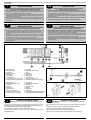
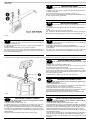
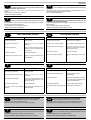
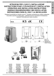
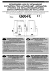
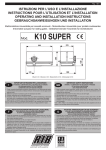
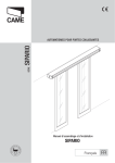
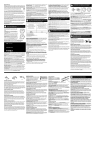
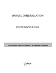
Pag. 1 di 8
ISTRUZIONI PER L'USO E L’INSTALLAZIONE
INSTRUCTIONS POUR L'UTILISATION ET L’INSTALLATION
OPERATING AND INSTALLATION INSTRUCTIONS
GEBRAUCHSANWEISUNGEN UND INSTALLATION
Elettroriduttore irreversibile per cancelli scorrevoli - Motoréducteur irreversible pour portails coulissantes
Irreversible actuator for sliding gates - Selbsthemmender Torantrieb für Schiebetüren
Mod.
K3
Misure in mm
Mesures en mm
Measurements in mm
Abmessungen in mm
I
IMPORTANTI ISTRUZIONI PER LA SICUREZZA
ATTENZIONE - É IMPORTANTE PER LA SICUREZZA DELLE PERSONE
CHE VENGANO SEGUITE TUTTE LE ISTRUZIONI
1° - Questo libretto d'istruzioni è rivolto esclusivamente a del personale specializzato che
sia a conoscenza dei criteri costruttivi e dei dispositivi di protezione contro gli infortuni per i
cancelli, le porte e i portoni motorizzati (attenersi alle norme e alle leggi vigenti).
2° - Tenete i comandi dell'automatismo (pulsantiera, telecomando etc.) fuori dalla portata dei
bambini. I comandi devono essere posti ad un’altezza minima di 1,5mt dal suolo e fuori dal
raggio d’azione delle parti mobili.
3° - Prima di eseguire qualsiasi operazione di installazione, regolazione, manutenzione
dell’impianto, togliere la tensione agendo sull’apposito interruttore magnetotermico collegato
a monte dello stesso.
ATTENZIONE - UNA SCORRETTA INSTALLAZIONE PUÓ PORTARE A DANNI RILEVANTI
LA DITTA RIB NON ACCETTA NESSUNA RESPONSABILITÀ per eventuali danni provocati
dalla mancata osservanza nell'installazione delle norme di sicurezza e le leggi attualmente in
vigore.
CONSERVARE CON CURA QUESTE ISTRUZIONI
F
INSTRUCTIONS IMPORTANTES POUR LA SECURITE
GB
IMPORTANT SAFETY INSTRUCTIONS
WARNING - IT IS IMPORTANT FOR THE SAFETY OF PERSONS
TO FOLLOW ALL INSTRUCTIONS
1° - This instruction booklet is exclusively dedicated to specialized staff who are aware of
the construction criteria and of the accident prevention protection devices for motorized
gates and doors (according to the current regulations and laws).
2° - Keep the automatic control (push-button, remote control, etc) out of the reach of children.
The control systems must be installed at a minimum hight of 1.5m from the ground surface
and not interfere with the mobile parts.
3° - Before starting any installation and operation or maintenance work make sure to cut off
power supply by turning the general magnetothermic switch off.
WARNING - INCORRECT INSTALLATION CAN LEAD TO SEVERE INJURY
R.I.B. IS NOT LIABLE for any damage caused by not following the safety regulations and laws at
present in force not being observed during installation.
SAVE THESE INSTRUCTIONS
D
WICHTIGE ANWEISUNGEN FÜR DIE SICHERHEIT
IL EST IMPORTANT POUR LA SECURITE DES PERSONNES
DE SUIVRE ATTENTIVEMENT TOUTES INSTRUCTIONS
1° - Ce manuel d'instruction est adressé seulement au personnel specialisé qui a une
connaissance des critères de construction et des dispositifs de protection contre les
accidents en ce qui concerne les portails, les portes et les portes cochères motorisées
(suivre les normes et les lois en vigueur).
2° - Gardez les commandes de l'automatisme (boutons poussoirs, télécommande etc.) hors de la
portée des enfants. Les commandes doivent être placées au minimum à 1,5 m du sol, et
hors de rayon d’action des pièces mobiles.
3° - Avant d’exécuter quelconques opérationd’installation, réglage, entrietien de l’installation,
couper la tension avec l’interrupteur magnétothermique approprié connecté en amont.
ACHTUNG - UM DIE SICHERHEIT VON PERSONEN VOLLKOMMEN
GARANTIEREN ZU KöNNEN, IST ES WICHTIG, DASS ALLE
1° - Diese Montageanweisung ist ausschließlich für geschultes Fachpersonal bestimmt,
das mit den Montagevorschriften und den Schutzvorrichtungen zur Verhinderung von
Unfällen bei motorisierten Toren vertraut ist (nach den aktuellen Normen und Gesetzen).
2° - Bewahren Sie die Geräte für die automatische Bedienung (Drucktaster, Funksender, u.s.w.)
an einem für Kinder unzugänglichen Platz auf. Die Steuerungen müssen auf einer
Mindesthöhe von 1,5 m angebracht werden und sich ausserhalb der Raumes der
bewegenden Teile befinden.
3° - Bevor Sie eine Installation oder Wartungsarbeit an der Anlage durchführen, müssen Sie
kontrollieren, dass die Anlage spannungsfrei geschaltet ist.
ATTENTION - UNE INSTALLATION INCORRECTE PEUT CAUSER DE GRANDS DOMMAGES
L'ENTREPRISE R.I.B. N'ACCEPTE AUCUNE RESPONSABILITÉ pour des dommages
éventuels provoqués par le manque d'observation lors de l'installation des normes de sécurité et
lois actuellement en vigueur.
ACHTUNG - EINE FALSCHE INSTALLATION KANN ZU BEDEUTENDEN SHÄDEN FÜHREN
R.I.B. HAFTET NICHT für eventuelle Schäden, die bei der Installation durch Nichtbeachtung der
jeweils gültigen Sicherheitsvorschriften entstehen.
INSTALLATIONSVORSCHRIFTEN BEACHTET WERDEN
GARDER MODE D’EMPLOI
Pag. 2 di 8
I
IMPORTANTI ISTRUZIONI DI SICUREZZA
PER L’INSTALLAZIONE
ATTENZIONE - UNA SCORRETTA INSTALLAZIONE PUÓ PORTARE A DANNI RILEVANTI
SEGUIRE TUTTE LE ISTRUZIONI PER UNA CORRETTA INSTALLAZIONE
1° - Questo libretto d'istruzioni è rivolto esclusivamente a del personale specializzato che sia a
conoscenza dei criteri costruttivi e dei dispositivi di protezione contro gli infortuni per i cancelli, le
porte e i portoni motorizzati (attenersi alle norme e alle leggi vigenti).
2° - Se non é previsto nella centralina elettrica, installare a monte della medesima un'interruttore di tipo
magnetotermico (onnipolare con apertura minima dei contatti pari a 3mm) che riporti un marchio di
conformità alle normative internazionali.
3° - Per la sezione ed il tipo dei cavi la RIB consiglia di utilizzare un cavo di tipo NPI07VVF con sezione
minima di 1,5mm2 e comunque di attenersi alla norma IEC 364 e alle norme di installazione vigenti
nel proprio Paese.
F
IMPORTANT MODE D’EMPLOI DE SECURITE
POUR L’INSTALLATION
ATTENTION - UNE INSTALLATION INCORRECTE PEUT CAUSER DE GRANDS DOMMAGES
SUIVRE TOUTES INSTRUCTIONS POUR UNE CORRECTE INSTALLATION
1° - Ce manuel d'instruction est adressé seulement au personnel specialisé qui a une
connaissance des critères de construction et des dispositifs de protection contre les accidents en ce
qui concerne les portails, les portes et les portes cochères motorisées (suivre les normes et les lois
en vigueur).
2° - A fin de procéder à l'entretien des parties électriques, connecter à l'installation un disjoncteur
differentiel magneto thermique (qui disconnait toutes les branchements de la ligne avec ouverture
min. des branchements de 3 mm ) et qui soit conforme aux normes internationales.
3° - Pour la section et le type des câbles à installer nous vous conseillons d’utiliser un cable <HAR>
avec une section min de 1,5 mm2 en respectant quand même la norme IEC 364 et les normes
nationales d'installation.
A - Elettroriduttore K3
B - Fotocellule esterne
C - Cremagliera
D - Selettore a chiave
E - Antenna radio
F - Lampeggiatore
G - Limitatori di corsa
L - Costa meccanica fissa sulle colonne
M - Costa pneumatica in punta al cancello
A - K3 operator
B - Photoelectric cells (external)
C - Rack
D - Key selector
E - Tuned aerial
F - Flashing lamp
G - Limit switch cam
L - Safety strip fixed to column
M - Pneumatic safety strip on edge of gate
A - Electro-réducteur K3
B - Photocellules p/protec. externe
C - Cremaillere
D - Selecteur
E - Antenne radio
F - Signal electrique
G - Camme en fin de course
L - Cordon mécanique fixé sur pilier
M - Cordon pneumatique sur portail
A - Torantrieb K3
B - Photozelle Toraussenseitig
C - Zahnstange
D - Schlußelschalter
E - Antenne
F - Blinkleuchte
G - Endschalter
L - Sicherheitskontaktleiste auf dem Schiebetor
M - Pneumatische Sicherheitskontaktleiste
IMPORTANT SAFETY INSTRUCTION
FOR INSTALLATION
WARNING -INCORRECT INSTALLATION CAN LEAD TO SEVERE INJURY
FOLLOW ALL INSTALLATION INSTRUCTIONS
1° - This instruction booklet is exclusively dedicated to specialized staff who are aware of the
construction criteria and of the accident prevention protection devices for motorized gates and
doors (according to the current regulations and laws).
2° - To maintain electrical parts safely it is advisable to equip the installation with a differential thermal
magnetic switch (onnipolar with a minimum opening of the contacts of 3mm) and must comply
with the international rules.
3° - As for electric cable type and section RIB suggests cable type <HAR> with minimum section of
1,5mm2 and however respect IEC 364 rule and general national security regulations.
D
WICHTIGE SICHERHEITSVORSCHRIFTEN
FÜR DIE INSTALLATION
ACHTUNG - EINE FALSCHE INSTALLATION KANN ZU BEDEUTENDEN SHÄDEN FÜHREN
FÜR EINE KORREKTE ANLAGE ALLE ANWEISUNGEN BEFOLGEN
1° - Diese Montageanweisung ist ausschließlich für geschultes Fachpersonal bestimmt, das
mit den Montagevorschriften und den Schutzvorrichtungen zur Verhinderung von Unfällen bei
motorisierten Toren vertraut ist (nach den aktuellen Normen und Gesetzen).
2° - Für die Wartung der elektrischen Teile ist es ratsam, zwischen der Anlage und dem
Netzanschluß einen magnetisch-thermischen Differenzialschalter (mit Mindestöffnung aller
Kontakte von 3 mm) zu montieren, der allen internationalen Normen entspricht.
3° - Für den Kabelquerschnitt und die Kabeltypen halten Sie sich an den Normen IEC 364 (MindestKabelquerschnitt von 1,5 mm2 mit der Bezeichnung <HAR>) und für die Montage an die Normen
des jeweiligen Landes.
Fig. 2
Fig. 3
Fig. 1
I
GB
CONTROLLO PRE-INSTALLAZIONE
N.B. È obbligatorio uniformare le caratteristiche del cancello alle norme e
leggi vigenti.
É necessario che la guida abbia alle sue estremità due fermi meccanici (L) (Fig. 2).
Inoltre, le colonne devono avere superiormente delle guide antideragliamento (Fig. 3).
Il cancello deve essere protetto da involontari sganciamenti.
N.B.: Eliminare fermi meccanici del tipo indicato descritto in figura 3.
Non devono essere presenti, al di sopra del cancello, fermi meccanici perché non
sufficientemente sicuri.
GB
PRE-INSTALLATION CHECKS
ATTENTION: It is compulsory to conform the gate characteristics to the
current regulations and laws.
The guide needs to have two mechanical stops (L) of the type indicated at its ends (Fig.
2).
In addition, the columns must have anti-deraillement guides at the top (Fig. 3).
The gate must be protected against unintentional derailment.
N.B. Eliminate the mechanical stops of the type indicated in Fig. 3.
There must be no mechanical stops above the gate, as they are not safe enough.
Pag. 3 di 8
CONTROLE PRE-INSTALLATION
F
N.B.: Il est obligatoire d’adapter les caracteristiques du portail aux
normes et lois en vigueur.
Il est nécessaire que le guidage ait à ses extrémités deux arrêts mécaniques (L) du type
indiqué (Fig. 2). En plus, les colonnes doivent avoir dans la partie supérieure des
guidages antidéraillement.
Eliminer les arrêts mécaniques du type décrit (Fig. 3).
Le portail doit être protégé contre des décrochages involontaires.
Ces arrêts mécaniques ne doivent pas être présents au-dessus du portail, car ils ne son
pas suffisamment sûrs.
I
ACHTUNG: Mann ist verpflichtet die Eigenschaften des Gittertures zu
die Gesetznormen in Einklang zu bringen.
Die Führungsschiene muß an beiden Enden mechanische Sperrunger (L) haben, wie in
der Abbildung dargestellt ist (Fig. 2). Darüberhinaus Mußen die Saulen über
Entgleisungsschutzvorrichtungen verfugen (Fig. 3).
Das Gitter soll gegen unvorgesehenes Entkuppeln geschützt sein.
Bitte beachten Sie: Entfernen Sie die beschriebenen mechanischen Sperrungen.
Über das Gittertor dürfen sich keine mechanischen Sperrungen befinden, da diese nicht
sicher genug sind.
CARATTERISTICHE TECNICHE
GB
Motoriduttore irreversibile per cancelli scorrevoli aventi un peso massimo
di 300 Kg.
L'irreversibilità di questo motoriduttore fa si che il cancello non richieda alcun tipo di
serratura elettrica per un'efficace chiusura.
Il motore è protetto da una sonda termica che in caso di utilizzo prolungato
dell'apparecchiatura, interrompe momentaneamente il movimento.
F
TECHNICAL DATA
Irreversible ratiomotor for sliding gates with a maximum weight of 300
Kg.
The fact that this ratiomotor is irreversible means that the gate does not need any type of
electric lock in order for it to close efficiently.
The motor is protected by a thermal probe which momentarily interrupts movement
should there be prolonged use.
CARACTERISTIQUES TECHNIQUES
Moto-réducteur irréversible pour portails coulissants ayant un poids
maximum de 300 Kg.
L’irréversibilité de ce moto-réducteur fait que le portail ne requiert aucun type de serrure
électrique pour une fermeture efficace.
Le moteur est protégé par une sonde thermique qui, en cas d’emploi prolongé,
interrompt momentanément le mouvement.
PRÜFUNG VON DER MONTAGE
D
TECHNISCHE EIGENSCHAFTEN
D
Selbsthemmender Torantrieb der für Schiebetoren mit einem maximalen
Gewicht von 300 Kg geeignet ist.
Dieser Motortyp benötigt kein zusätzliches Elektroschloß.
Der Motor ist durch eine Wärmesonde geschützt, die bei längerer Benutzung die
Bewegung vorübergehend unterbricht.
CARATTERISTICHE
TECNICHE
CARACTERISTIQUES
TECHNIQUES
TECHNICAL
DATA
TECHNISCHE
EIGENSCHAFTEN
Peso max cancello
Poids maxi du portail
Max. leaf weight
Max. Torgewicht
K3
Kg
300
Velocità di traino
Vitesse de traction
Operating speed
Laufgeschwindigkeit
m/sec
Forza max di spinta
Force maxi de poussée
Thrust force
Max. Schubkraft
N
0,160
Cremagliera modulo
Module crémaillère
Rack
Zahnstange Modul
Alimentazione e frequenza CEE
Alimentation et frequence CEE
EEC Power supply
Stromspannung und frequenz CEE
Potenza motore
Puissance moteur
Motor capacity
Motorleistung
W
270
Assorbimento
Absorption
Power absorbed
Stromaufnahme
A
1,16
Condensatore
Condensateur
Capacitor
Kondensator
µF
10
n° di cicli
Nbre de cycles
No. cycles
Anzahl der Zyklen
n°
Alimentazione e frequenza
Alimentation et frequence
Power supply
Stromspannung und frequenz
Potenza motore
Puissance moteur
Motor capacity
Motorleistung
W
151
Assorbimento
Absorption
Power absorbed
Stromaufnahme
A
0,96
Condensatore
Condensateur
Capacitor
Kondensator
µF
6,3
n° di cicli
Nbre de cycles
No. cycles
Anzahl der Zyklen
n°
20 - 18s/2s
Alimentazione e frequenza
Alimentation et frequence
Power supply
Stromspannung und frequenz
Potenza motore
Puissance moteur
Motor capacity
Motorleistung
W
192
Assorbimento
Absorption
Power absorbed
Stromaufnahme
A
1,74
Condensatore
Condensateur
Capacitor
Kondensator
µF
30
n° di cicli
Nbre de cycles
No. cycles
Anzahl der Zyklen
n°
11 - 18s/2s
Lubrificazione a grasso
Graisse
Grease
Schmiere
Peso max
Poids maximun
Weight of electroreducer
Motorgewicht
Kg
Rumorosità
Bruit
Noise
Geräusch
db
<70
Volume
Volume
Volume
Volumen
m3
0,015
Grado di protezione
Indìce de protection
Protection
Schutzart
IP
545
550
4
230V~ 50Hz
17 - 18s/2s
220V~ 60Hz
110V~ 60Hz
Bechem - RHUS 550
7,5
Pag. 4 di 8
N° cicli = Numero di manovre complete minime garantite (apre+chiude),
ammettendo un tempo massimo di funzionamento di 18 secondi con 2
secondi di pausa tra i movimenti (tempo di funzionamento e tempo minimo di pausa tra
le manovre settati su centralina RIB S111).
No. cycles = minimum number of guaranteed complete movements
(open+close), allowing 18 seconds maximum operating time with a 2
second pause between movements (operating time and minimum pause time for the
movements set on the RIB S111 control board).
Il N° cicli aumenta quanto più breve è il tempo di funzionamento e lungo il tempo di
pausa tra le manovre.
The number of cycles increases as the operation time decreases, with respect to the
pause time between movements.
N° cicli = N° di manovre complete conteggiate fino al raggiungimento di una
temperatura del motore di 115°C (con motore a pieno carico con temperatura di avvio di
25°C).
No. cycles = number of complete movements carried out before the motor temperature
reaches 115°C (with motor at full load and starting temperature of 25°C).
I
GB
No. cycles = the motor shows no sign of overheating after completing these cycles.
N° cicli = Non indica che il motore subito dopo aver eseguito queste manovre vada in
termica.
Nbre de cycles = Nbre minimum de manoeuvres complètes garanties
(ouverture + fermeture), en admettant un temps maximum de
fonctionnement de 18 secondes avec 2 secondes de pause entre les mouvements
(temps de fonctionnement et temps minimum de pause entre les mouvements
programmés sur le coffret électronique RIB S111).
F
Plus le temps de fonctionnement est bref et plus le temps de pause entre les
manoeuvres est long, plus le nombre de cycles augmente.
Nbre de cycles = Nbre de manoeuvres complètes comptées avant que le moteur n’ait
atteint une température de 115 °C (avec moteur à pleine puissance et température de
démarrage de 25 °C).
Anzahl der Zyklen = Mindestanzahl der garantierten kompletten
Bewegungen (Öffnen + Schließen), wobei die max. Betriebszeit 18
Sekunden mit 2 Sekunden Pause zwischen den Bewegungen (auf der Steuertafel RIB
S111 programmierte Betriebszeit und minimale Pause zwischen den Bewegungen).
D
Die Zyklenanzahl erhöht sich, wenn die Betriebszeit kürzer und die Pause zwischen den
Bewegungen länger wird.
Anzahl der Zyklen = Anzahl der kompletten Bewegungen bis der Motor eine Temperatur
von 115°C erreicht (bei voller Motorleistung mit einer Anfangstemperatur von 25°C).
Anzahl der Zyklen = Zeigt nicht an, daß der Motor sofort nach diesen Bewegungen
blockiert wird.
Nbre de cycles = Ne signifie pas que le moteur se met en veille immédiatement après
l’exécution de ces manoeuvres.
I
FISSAGGIO MOTORE E CREMAGLIERA
F
INSTALLATION DU MOTOR E DE LA CREMAILLERE
La base dell'elettroriduttore K3 è dotata di 2 zanche così da poterlo
cementare al suolo.
La cremagliera va fissata a una certa altezza rispetto alla piastra di fissaggio del motore.
Questa altezza può essere variata grazie a delle asole presenti sulla cremagliera.
Le cremagliere non devono essere saldate, ma solo fissate con delle viti filettate al
cancello. La registrazione in altezza viene fatta affinché il cancello durante il movimento,
non si appoggi sull'ingranaggio di trazione del riduttore (Fig. 4,5).
Per fissare la cremagliera sul cancello si eseguono dei fori di Ø 7 mm e si filettano
utilizzando un maschio del tipo M8.
L'ingranaggio di traino deve avere circa da 0,5 a 1 mm di agio rispetto alla cremagliera.
La base du moto-réducteur est équipée de 2 agrafes pour pouvoir être
cimentée au sol.
La crémaillère doit être fixée à une certaine hauteur par rapport à la base du moteur.
Cette hauteur peut être modifiée grâce à des boutonnières qui sont présentes sur la
crémaillère. La crémaillère ne doit pas être soudée mais seulement fixée avec des vis
filetées à la grille.
Le réglage en hauteur est effectué afin que le portail ne s'appuie pas sur l'engrenage de
traction du réducteur (Fig. 4,5). Afin de fixer la crémaillère sur la grille, on perce des trous
de 7 mm de diamètre et on les filète en employant un taraud du type M8.
L'engrenage de tirage doit avoir un jeu de 0,5 à 1 mm en rapport à la crémaillère.
GB
D
INSTALLATION DES ANTRIEBS UND DER ZAHNSTANGE
Die Antriebsverankerungsplatte hat 2 Hacken, um sie auf Boden zu
befestigen.
Die Zahnstange muß in bestimmten Abstand von der Verankerungsplatte befestigt
werden. Die Höhe kann mit Hilfe der auf der Zahnstange befindlichen Ösen verstellt
werden. Die Zahnstange darf nicht angeschweißt, sondern nur mit Hilfe von
Gewindeschrauben an dem Gittertor befestigt werden. Die Höheneinstellung soll
verhindern, daß das Gittertor auf dem Antriebszahnrad des Antriebes aufliegt. (Abb. 4,5).
Um die Zahnstange am der Gittertor fixieren werden Locher mit einem Durchmesser von
7 mm gebohrt, in die ein Gewinde M8 eingeschnitten wird.
Das Zugzahnrad muß gegenüber der Zahnstange ein Spiel von 0,5 bis 1 mm haben.
Misure in mm
Mesures en mm
Measurements in mm
Abmessungen in mm
Fig. 4
MOTOR AND RACK INSTALLATION
The base of the ratiomotor is equipped with 2 anchors so that it can be
cemented to the ground.
The rack must be fixed at a certain height with respect to the motor base.
This height can be varied thanks to the slots on the rack.
The rack must not be welded, but simply fixed to the gate with threaded screws.
The height needs to be adjusted so that the gate does not rest on the reduction unit
traction gear (Fig. 4,5).
Holes with a diameter of 7 mm should be made to fix the rack into the gate, and they
should be threaded using a M8 type screw tap.
The pinion must have a clearance of 0,5 to 1 mm with respect to the rack.
Fig. 5
Pag. 5 di 8
A) Cancello
Portail coulissant
Sliding gate
Schiebetoren
B) Fotocellule esterne
Cellules pour l'exterieur
External photo-electric cells
Photozelle - Außenseitig
L) Costa meccanica fissa sulle colonne
Cordon mécanique fixé sur pilier
Safety strip fixed to column
icherheitskontaktleiste auf dem Schiebetor
Fig. 6
I
SICUREZZE ELETTRICHE
Realizzare l’impianto in ottemperanza alle norme ed alle leggi vigenti.
Si consiglia l'utilizzo della centralina elettronica di comando AQM11 (per 1 motore
monofase).
Per i collegamenti ed i dati tecnici degli accessori attenersi ai relativi libretti.
F
SECURITES ELECTRIQUES
Adapter les installation du parties electriques aux normes et lois en
vigueur.
Nous vous conseillons d’utiliser le coffret électronique AQM11 (pour 1 moteur
monophasés).
Pour ce qui est des raccordements et des données techniques des accessoires, se
référer à leur manuel.
GB
ELECTRIC SAFETY DEVICES
The installation must be installed according to the current regulations
and laws.
Use the AQM11 (for one single-phase motor) electronic control unit.
For connections and technical data of accessories refer to the appropriate booklets.
D
ELEKTRISCHE SICHERHEITSVORRICHTUNGEN
F
MANOEUVRE DE SECOURS
GB
EMERGENCY RELEASE
D
NOTENTRIEGELUNG
Die Installation muß nach die aktuellen Gesetznormen installiert werden.
Es wird die Verwendung der elektronischen Steuergeräte AQM11 (für 1 einphasige
Motor) empfohlen.
Für die Anschlüsse und technische Daten der Zubehörteilen verweisen wir auf die
entsprechenden Bedienungshandbücher.
Effectuer seulement apres avoir coupé l'alimentation.
L'electro-reducteur étant irreversible, il n'est pas necessaire de monter une serrure.
Pour ouvrir manuellement le portail en cas de panne de courant, tourner la clé RIB dans
le sens horaire.
Pour revenir à un fonctionnement electrique tourner-le en sens contraire (Fig. 7).
To be undertaken after disconnecting power supply.
The operator is irreversible and keeps the door closed even without a lockset.
To open the gate manually, in case of power failure, you should turn RIB key clockwise.
To restore electric working you have to turn the lever anti-clockwise (Fig. 7).
Fig. 7
I
SBLOCCO D'EMERGENZA
Da effettuare dopo aver tolto l'alimentazione elettrica al motore.
L'elettroriduttore è di tipo irreversibile e tiene chiuso senza l'ausilio di serrature.
Per poter aprire manualmente il cancello, qualora venisse a mancare l'energia elettrica,
ruotare la chiave RIB in senso orario.
Per ripristinare il funzionamento elettrico operare in senso contrario (Fig. 7).
Die Wartungsarbeit nur nach der Ausschliessung der Spannung auszuführen.
Dieser Schiebetorantrieb ist selbsthemmend, so daß ein zusätzliches Elektroschloß
überflüssig ist . Um das schiebetor Tor beim Stromausfall entriegeln zu können, drehen
Sie den RIB Schlüssel Im Uhrzeigersinn.
Um das Schiebetor wieder im Betrieb zu setzen, drehen Sie ihn in die umgekehrte
Richtung (Abb. 7).
Pag. 6 di 8
F
REGLAGE FIN DE COURSE
GB
LIMIT SWITCH ADJUSTMENT
D
EINSTELLUNG DES ENDSCHALTERS
L'arrêt du portail est obtenu avec 2 cames montées aux extrémités de la
crémaillère (Fig. 8).
Le réglage de la course d'ouverture et de fermeture s'obtient en déplaçant la came sur
les dents de la crémaillère.
Pour fixer la came visser à fond la vis (1), puis bloquer le contre écrou (2).
N B. Avec les fins de course électriques, il faut monter des butées mécaniques a fin que
le portail ne sorte pas de son guide supérieur.
The gate stops thanks to the two cams, which are placed at each end of
the rack (Fig. 8).
The regulation of the opening and closing stroke can be obtained by displacing these on
the rack.
To fix the cam, screw the screws (1 ) and the nuts (2) rightly.
N.B.: In addition to the above-mentioned limit switch it is compulsory to install solid
mechanical stops, which prevent the gate from sliding off the upper guide bearings.
Fig. 8
I
REGOLAZIONE FINECORSA
L'arresto del cancello avviene attraverso le due camme montate alle
estremità della cremagliera (Fig. 8).
La regolazione della corsa di apertura e chiusura, si ottiene spostando le medesime sui
denti della cremagliera.
Per fissare la camme, avvitare a fondo le viti (l) e avvitare poi i dadi (2) .
N.B: Oltre alle camme di fermo elettrico sopraesposte è obbligatoria l'installazione di
fermi meccanici robusti che non permettono la fuori uscita del cancello dalle guide
superiori (Per l'Italia NORME UNI 8612).
Der Toranschlag ist mit zwei Metallbügeln, die an der Zahnstange
angebracht sind, gegeben (Abb. 8).
Die Weite der Toröffnung erfolgt mit der Verstellung der Metallbügeln.
Um die Metallbügeln zu fixieren, die Schraube (1) festziehen und die Schraubenmutter
(2) einschrauben.
N.B. Außer dem oben beschriebenen Metallbügeln ist eine mechanische
Feststellvorrichtung vorgeschrieben, um eine Torentgleisung verhindern zu konnen.
F
REGLAGE EMBRAYAGE DE SECURITE
Ces operations doivent être executées aprés avoir coupé
I'alimentation.
1) Dévisser l'écrou (4) à l'aide d'une clef plate de 13 mm.
2) Maintenir l'arbre moteur à l'aide d'une clef plate de 10 mm et serrer la vis (3) pour
donner plus de couple. Désserer pour le diminuer.
3) Après obtention du réglage voulu, bien bloquer le contre-écrou (4) sur l'arbre moteur.
Faire coulisser le portail électriquement à plusieurs reprises en retenant celui-ci avec les
mains, de manière que la force de poussée soit légèrement supérieure à celle requise
pour mettre le portail en mouvement.
Le réglage effectué, se rappeler de bloquer l'écrou contre l'arbre moteur.
GB
ADJUSTMENT OF THE SAFETY CLUTCH
D
EINSTELLUNG DER SICHERHEITSKUPPLUNG
N.B.: These operations must be executed only after the power
supply has been suspended.
1) Unscrew the unit with a 13 mm wrench (4).
2) Hold the motor with a 10 mm wrench and turn the screw (3) clockwise (with the given
wrench) if you want more force or unscrew it if you need less.
3) After regulating the clutch do not forget to clamp the nut (4) at the shaft's end.
Let the gate move electrically a number of times, holding it with your hands so that the
thrust force is slightly higher than that actually required to move the gate.
When adjustment has been completed, remember to fasten the nut at the motor shaft.
Fig.9
I
REGOLAZIONE FRIZIONE DI SICUREZZA
N.B.: Queste operazioni devono essere eseguite dopo avere tolto
l'alimentazione elettrica del motore.
1 ) Allentare il dado (4) con chiave fissa da 13 mm.
2) Trattenere l'albero motore con chiave fissa da 10 mm e awitare la vite (3) in senso
orario se si vuole dare maggior potenza di spinta, antiorario se serve meno spinta.
3) A regolazione avvenuta ricordarsi di ribloccare il dado (4) contro l'estremità dell'albero.
Far scorrere il cancello elettricamente più volte trattenendolo con le mani, in modo che la
forza di spinta sia leggermente superiore a quella richiesta per movimentare il cancello
(NORME UNI 8612).
A regolazione avvenuta ricordarsi di bloccare il dado contro l'albero motore.
N.B.: Diese Operationen sind nur ausführbar nachdem der Antrieb
aus dem Netz ausgeschaltet worden ist.
1) Die Mutterschraube (4) ist mit dem 13 mm Maulschluessel zu lockern.
2) Die Antriebswelle ist mit einem 10 mm Maulschluessel festzuhalten und gleichzeitig
die Schraube (3) mit dem dazugehöerenden Schlüessel im Uhrzeigerssinn anzuziehen,
wenn Sie dem Antrieb mehr Schubleistung geben moechten, dagegen, wenn Sie
weniger Schubleistung brauchen, ist die Schraube gegen den Uhrzeigsinn zu lockern.
3) Nach der Einstellung der Rutschkupplung ist die Schraubenmutter (4) wieder gegen
Antriebswelle festzuschrauben.
Lassen Sie das Tor nun einige Male hin- und hergleiten Halten Sie es mit den Händem
zurück, um die Druckkraft leicht über der für die Torbewegung notwendige zu liegen.
Nach erfolgter Einstellung ist die Schraubenmutter wieder gegen die Motorwelle
anzuziehen.
Pag. 7 di 8
MANUTENZIONE
I
Da effettuare solamente da parte di personale specializzato dopo
aver tolto l'alimentazione elettrica al motore.
Pulire periodicamente, a cancello fermo, la guida di scorrimento da sassi e altra
sporcizia.
In caso di problemi nell'installazione consultare la
"TABELLA DEI POSSIBILI PROBLEMI".
F
ENTRETIEN
Effectuer soulement par personnel specialisé après avoir coupé
l'alimentation.
Seulement quand le portail n'est pas en mouvement nettoyer périodiquement la glissière
afin d'en enlever les cailloux et autre saleté.
En cas de difficultés lors de l'installation, consulter le
"TABLEAU DES DIFFICULTES POSSIBLES".
TABELLA DEI POSSIBILI PROBLEMI
I
Problema
GB
MAINTENANCE
To be undertaken only by specialized staff after disconnecting
power supply.
Clean the sliding guide of stones and dirt periodically only when the gate does not move.
If there are any problems during installation, consult the
"LIST OF POSSIBLE PROBLEMS".
D
WARTUNG
GB
LIST OF POSSIBLE PROBLEMS
Die Wartungsarbeit nur durch spezialiesierten Fachleuten nach der
Ausschliessung der Spannung auszuführen.
Saubern Sie regelmäßig beim nicht bewegenden Tor die Laufschiene von Steinen oder
anderem Schmutz.
Sofern Installationsprobleme auftreten, ziehen Sie die
"TABELLE VON EVENTUELLEN PROBLEMEN" zu Rate.
Soluzione
Problem
Solution
K3 non apre, ma chiude
Invertire V con W
K3 does not open, but closes
Invert on the motor V instead W
K3 non si ferma sui finecorsa
Invertire il filo 4 col filo 7 sul quadro
elettronico
K3 does not stop on the limit switches
Invert 4 instead 7 on the electronic panel
K3 has not the force to move the gate
K3 non ha forza di traino
Agire sulla frizione tanto quanto basta a
ripristinare il moto del cancello senza
forzarlo (Fig. 9).
Operate the clutch as much as i
necessary to reset the gate movement
without forcing it (Fig. 9).
The motor does not work
Control the connections
ll motore non funziona
Controllare l'alimentazione.
The motor stops after few seconds
ll motore dopo pochi secondi si ferma
Regolare il tempo di funzionamento sul
quadro elettronico
Adjust the operating timer on the control
box
F
TABLEAU DES DIFFICULTES POSSIBLES
Problème
D
TABELLE EVENTUELL AUFTRETENDER PROBLEME
Probleme
Solution
Lösung
K3 n'ouvre pas, mais il ferme
Inverser V avec W
K3 offnet nicht, sondern schließt nur
Invertieren Sie V und W.
K3 ne s'ârrette pas sur les fins de course
Inverser 4 avec 7 sur le coffret
électronique
K3 halt bei den Endschaltern nicht an
Invertieren sie 4 und 7 auf die
Anschlußklemme
K3 n'a pas de force de traction
Opérer sur l'embrayage autant qu'il faut
afin de rétablir le mouvement du portail
sans le forcer (Fig. 9)
K3 hält keine Zugkraft
Betatigen Sie die Kupplung so lange bis
das Tor sich wieder normal bewegt, ohne
es dabei zu belasten (Abb. 9).
Le moteur ne fonctionne pas
Controler l'alimentation.
Der Motor funktioniert nicht
Überprüfen Sie die Stromversorgung.
Le moteur s'ârrete après quelques Régler le timer de fonctionnement sur le
coffret électronique.
secondes.
I
N.B.:É obbligatoria la messa a terra dell'impianto
F
N.B:La mise à la terre de l'installation est obligatoire
I dati descritti nel presente manuale sono puramente indicativi.
La RIB si riserva di modificarli in qualsiasi momento.
Realizzare l’impianto in ottemperanza alle norme ed alle leggi vigenti.
Les donnees techniques decrites dans ce present manuel sont purement
a titre indicatif.
La RIB se reserve le droit de les modifier à n'importe quel moment.
Adapter les installation du parties electriques aux normes et lois en vigueur.
Der Motor hält nach wenigen Sekunden Stellen Sie den Timer richtig ein.
an.
GB
N.B.: The system absolutely must be earthed.
The technical data given in this manual are only aproximate.
RIB reserves the right to modify technical data at any time without previous notice.
The installation must be installed according to the current regulations and laws.
D
Bitte beachten Sie: Das Erden der Anlage ist obligatorish
Die in dem vorliegenden Handbuch angegebenen technischen Dater sind
rein informativ.
Firma RIB behalt sich das Rech vor, sie jederzeit zu ändern.
Die Installation muß nach die aktuellen Gesetznormen installiert werden.
Pag. 8 di 8
Denominazione Particolare
Gruppo "EURO11CRX" + piastra K3
Gruppo "EURO11" + piastra K3
Gruppo “BRA111” BRASIL c/cont.
Gruppo "EURO11CRX" 110/60
Gruppo "AQM11" + piastra K3
BC00151
BC00152
BC00168
BC00182
BC93051
BC93052
BC93110
BC93115
Scheda EURO11CRX 230-50/60
Scheda EURO11 230-50/60
Scheda EURO11CRX 110-60
Scheda EURO11 110-60
Scheda BRA111 230-50/60
Scheda BRA111 110-60
Scheda AQM11 230-50/60
Scheda AQM11 110-60
CAL1155
CAL1280
CAL1516
CAL1517
CCA1217
Codice
Denominazione Particolare
CCA1218
CCM6205
CCM6301
Piastra di base
Cuscinetto motore 6205ZZ
Cuscinetto motore 53012RS
CEL1078
CEL1351
CEL1375
CEL1384
CEL1425
Passacavo
Microswitch a rotella
Condensatore 30µF
Condensatore 6,3µF
Condensatore 10µF
CME1039
CME1040
CME6071
CME9300
Albero motore K3
Albero di traino
Anello spingi disco
Ferodo frizione
Corona
Ingranaggio di traino
Campana K3
Carcassina alluminio
CMO1076
CMO1077
CMO1078
CMO1202
Statore 110/60 1P
Statore 220/60 1P
Statore 230/50 1P
Rotore
Piastra porta quadro K3
CPL1024
Supporto in PVC 032 per condensat.
®
Codice
Denominazione Particolare
CPL1034
CPL1099
CPL1201
CPL1202
CPL1203
CPL1206
Contenitore plastico serie K
Chiave di sblocco
Carter di copertura
Sfera per molla finecorsa
Flangia anteriore finecorsa
Boccola
CTC1090
CTC1149
CTC1203
CTC1204
CTC1205
CTC1214
CTC1218
CTC1303
Paraolio 20x30x5
Spessore 12 18 1 DIN988
Molla per finecorsa
Molla frizione K3-K5
Molla di sblocco
Spina cilindrica 8X32
Spina cilindrica 10x45
Anello di tenuta OR158
CVA1060
CVA1078
Guarnizione per cont. serie K
Boccola 15x18x12 Bronzo A50
DST12X70
DTB8x12I
Grano M12x70
Vite TCEI 8x12 inox
25014 CASTENEDOLO (BS)-ITALY
Via Matteotti, 162
Telefono ++39.030.2135811
Telefax ++39.030.21358279-21358278
automatismi per cancelli
http://www.ribind.it
- email: [email protected]
automatic entry systems
La presente macchina non può funzionare in modo
indipendente ed è destinata ad essere incorporata in
un impianto costituito da ulteriori elementi. Rientra
perciò nell’Art. 4 paragrafo 2 della Direttiva
89/392/CEE (Macchine) e successive modifiche, per
cui segnaliamo il divieto di messa in servizio prima che
l’impianto sia stato dichiarato conforme alle
disposizioni della Direttiva
Il Presidente
Cod. CVA1212 - 18/09/2002 - Rev. 08
Codice
BA03065
BA03068
BA03108
BA03111
BA03120