1
Safe Operation
Practices • Set-Up • Operation
• Maintenance
PERATOR S
• Service • Troubleshooting
• Warranty
ANUAL
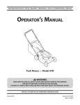
Hydrostatic Lawn Tractor m LT1045
CUB CADET LLC, P.O. BOX 361131 CLEVELAND, OHiO 44136-0019
PrintedIn USA
FormNo.769-03399A
(November21,2007)
1
ToTheOwner
ThankYou
Thank you for purchasing
a Lawn Tractor manufactured
Cadet LLC. It was carefully engineered
performance
when properly operated
Please read this entire
It instructs
maintain
persons
manual
prior to operating
This product has met the rigid safety standards
Power Equipment
Institute and an independent
laboratory.
directly.
and
the machine,
carefully
follow
Cub Cadet's Customer
the
Throughout
All information
The engine
product
in this manual
information
available
is relative
to the most recent
at the time of printing.
Review
warranty
concerning
this manual,
are observed
telephone
can be found
satisfaction
all references
manufacturer
is responsible
us
numbers,
on this page.
at all times.
to right and left side of the
from the operating
position
for all engine-related
power-rating,
and service. Please refer to the engine
Owner's/Operator's
Manual, packed separately
machine, for more information.
Manual may cover a range of product specifications
for various
models. Characteristics
and features discussed and/or illustrated
may not be applicable
address
issues with regards to performance,
this manual frequently to familiarize yourself with the machine,
its features and operation.
Please be aware that this Operator's
in this manual
machine
or questions
Support
We want to ensure your complete
recommended
safety practices at all times. Failure to do so could
result in personal injury or property damage.
of the Outdoor
testing
phone your local Cub Cadet dealer or contact
web site address and mailing
Please be sure that you, and any other
who will operate
If you have any problems
the machine,
the equipment.
you how to safely and easily set up, operate
your machine.
by Cub
to provide excellent
and maintained.
specifications,
manufacturer's
with your
to all models. Cub Cadet
LLC reserves the right to change product specifications,
designs
and equipment
without
notice and without incurring obligation.
Table of Contents
Safe Operation
Practices ........................................
3
Assembly & Set-Up ..................................................
Controls & Features ................................................
8
11
Operation
15
................................................................
Maintenance
& Adjustment
..................................
up and operating
plate by looking
be necessary,
beneath
your new equipment,
please
the seat. This information
should you seek technical
site, Customer Support
service dealer.
Department,
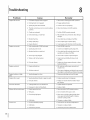
Troubleshooting
30
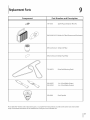
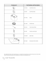
Replacement
Attachments
....................................................
Parts .................................................
& Accessories ..................................
31
33
MODEL NUMBER
locate the model plate on the equipment
and record the
information
in the provided area to the right. You can locate the
model
23
19
RecordProductinformation
Before setting
Service ....................................................................
support
DFI[3FI[3FI[3FI[3F1D
will
SERIALNUMBER
via our web
or with a local authorized
DNDNDNDNDND
CustomerSupport
If you have difficulty
this machine,
assembling
this product
you can seek help from
or have any questions
the experts.
Choose
from
regarding
the options
0
Visit us on the web at www.cubcadetcom
0
Call a Customer Support Representative
0
Locate your nearest Cub Cadet Dealer at (877) 282-8684
0
Write us at Cub Cadet LLC • P.O. Box 361131 • Cleveland, OH • 44136-0019
at (800) 965-4CUB
the controls,
below:
operation,
or maintenance
of
2
importantSafeOperationPractices
WARNING:
This symbol
could endanger
points
the personal
all instructions
safety and/or
in this manual
with these instructions
out important
before
property
attempting
may result in personal
When you see this symbol.
safety instructions
of yourself
to operate
which,
if not followed,
and others. Read and follow
this machine.
Failure to comply
injury.
HEED ITS WARNING!
CALIFORNIA
PROPOSITION
65
WARNING: Engine Exhaust, some of its constituents,
and certain vehicle components
contain or emit chemicals known to State of California to cause cancer and birth defects
or other reproductive
,A
WARNING:
compounds,
Battery
harm.
posts, terminals,
chemicals
known
and related
to the State of California
this manual.
operator
was built to be operated
As with any type of power
objects.
serious injury
or death.
Failure to observe
Read, understand,
future
and follow
all instructions
and operate.
Keep this manual
reference
in a safe place for
and for ordering
replacement
7.
Be familiar with all controls and their proper operation.
Know how to stop the machine and disengage them
Never allow children under 14 years of age to operate this
machine. Children 14 and over should read and understand
blade contact
this machine
or a thrown
without
object
hands and feet
could
result in
the area where the equipment
which
could
is to be
be picked up and thrown
objects
by
can cause serious personal
Plan your mowing
pattern
roads, sidewalks,
to avoid discharge
bystanders
material
8.
10.
operation
and while performing
to protect
your eyes. Thrown
during
an adjustment
objects
which
back
or repair
ricochet
can
Wear sturdy, rough-soled
work shoes and close-fitting
slacks and shirts. Loose fitting clothes and jewelry can be
caught in movable parts. Never operate
bare feet or sandals.
this machine
Be aware of the mower
discharge
without
proper
11.
to ricochet
to the eyes.
and attachment
and do not point it at anyone.
enters the area.
material
Always wear safety glasses or safety goggles
cause serious injury
injury,
of material
and the like. Also,
against a wall or obstruction
which may cause discharged
toward the operator.
proper
keep bystanders, helpers, children and pets at least 75 feet
from the machine while it is in operation.
Stop machine if
anyone
objects
avoid discharging
9.
Never allow adults to operate
instruction.
To help avoid
inspect
in
injury.
toward
by an adult.
5_
of amputating
safety instructions
Thoroughly
practices
or error on the part of the
the blade(s). Thrown
the instructions
and safe operation practices in this manual
and on the machine and should be trained and supervised
4.
is capable
foreign
to
quickly.
3.
carelessness
the following
on the
attempting
pa rts.
2.
to the safe operation
used. Remove all stones, sticks, wire, bones, toys, and other
and in the manual(s) before
and regular
equipment,
6.
GeneralOperation
assemble
lead and lead
to cause cancer and reproductive
according
can result in serious injury. This machine
and throwing
machine
contain
harm. Wash hands after handling
DANGER: This machine
1.
accessories
the discharge
Do not operate
cover or entire
in
direction
the mower
grass catcher
in its
place.
Do not put hands or feet near rotating parts or under the
cutting deck. Contact with the blade(s) can amputate
hands and feet.
12. Amissing
ordamaged
discharge
cover
cancause
blade
Slope Operation
contact
orthrown
object
injuries.
Slopes are a major factor related to loss of control and tip-over
13. Stoptheblade(s)
whencrossing
gravel
drives,
walks,
or
accidents which can result in severe injury or death. All slopes
roads
andwhilenotcutting
grass.
require extra caution. If you cannot back up the slope or if you
feel uneasy on it, do not mow it.
14. Watch
fortrafficwhenoperating
nearorcrossing
roadways.
Thismachine
isnotintended
foruseonany
For your safety, use the slope gauge included as part of this
publicroadway.
manual to measure slopes before operating this machine on
a sloped or hilly area. If the slope is greater than 15 degrees as
15. Donotoperate
themachine
whileunder
theinfluence
of
shown on the slope gauge, do not operate this machine on that
alcohol
ordrugs.
area or serious injury could result.
16. Mowonlyindaylight
orgoodartificial
light.
Do:
17. Never
carrypassengers.
1.
Mow up and down slopes, not across. Exercise extreme
18. Disengage
blade(s)
before
shifting
intoreverse.
Back
up
caution when changing direction on slopes.
slowly.
Always
lookdownandbehind
before
andwhile
backing
toavoid
aback-over
accident.
2.
Watch for holes, ruts, bumps, rocks, or other hidden
objects. Uneven terrain could overturn the machine. Tall
19. Slow
downbefore
turning.
Operate
themachine
smoothly.
grass can hide obstacles.
Avoid
erratic
operation
andexcessive
speed.
3.
Use slow speed. Choose a low enough speed setting so
20. Disengage
blade(s),
setparking
brake,
stopengine
and
that you will not have to stop or shift while on the slope.
waituntiltheblade(s)
come
toacomplete
stopbefore
Tires may lose traction on slopes even though the brakes
removing
grass
catcher,
emptying
grass,
unclogging
chute,
are functioning
properly. Always keep machine in gear
removing
anygrass
ordebris,
ormaking
anyadjustments.
when going down slopes to take advantage of engine
21. Never
leave
arunning
machine
unattended.
Always
turn
braking action.
offblade(s),
place
transmission
inneutral,
setparking
4.
Follow the manufacturer's
recommendations
for wheel
brake,
stopengine
andremove
keybefore
dismounting.
weights or counterweights
to improve stability.
22. Useextracarewhenloading
orunloading
themachine
into
atrailerortruck.
Thismachine
should
notbedriven
upor 5. Use extra care with grass catchers or other attachments.
These can change the stability of the machine.
downramp(s),
because
themachine
couldtipover,
causing
serious
personal
injury.
Themachine
mustbepushed
6.
Keep all movement on the slopes slow and gradual. Do
manually
onramp(s)
toloadorunload
properly.
not make sudden changes in speed or direction.
Rapid
engagement
or braking could cause the front of the
23. Muffler
andengine
become
hotandcancause
aburn.Do
machine to lift and rapidly flip over backwards which could
nottouch.
cause serious injury.
24. Check
overhead
clearances
carefully
before
driving
under
7.
Avoid starting or stopping on a slope. If tires lose traction,
lowhanging
treebranches,
wires,
dooropenings
etc.,
disengage the blade(s) and proceed slowly straight down
where
theoperator
maybestruck
orpulled
fromthe
the slope.
machine,
whichcouldresult
inserious
injury.
25. Disengage
allattachment
clutches,
depress
thebrake
Do Not:
pedal
completely
andshiftintoneutral
before
attempting 1. Do not turn on slopes unless necessary; then, turn slowly
tostartengine.
and gradually downhill, if possible.
26. Your machine is designed to cut normal residential grass of
a height no more than 10". Do not attempt
unusually
tall, dry grass (e.g., pasture)
Dry grass or leaves may contact
build up on the mower
hazard.
27.
to mow through
deck presenting
a potential
all instructions
provided
to operate
4.
Do not use a grass catcher on steep slopes.
5.
Do not mow on wet grass. Reduced traction
should
themselves
and others from
If situations
occur which
evaluate
the machine
Do not shift to neutral
7.
to protect
and coast downhill.
I
SECTION 2 --
IMPORTANT SAFE OPERATION
could cause
Over-speeding
of the machine
Do not tow heavy pull behind attachments
dump
serious injury.
in this manual,
care and good judgment.
Contact your customer
representative
for assistance.
4
your foot on
their ability
safely enough
are not covered
by putting
may cause the operator to lose control
resulting in serious injury or death.
PRACTICES
service
use
(e.g. loaded
cart, lawn roller, etc.) on slopes greater than 5
degrees. When going down
29.
The
sliding.
6.
the riding mower
or embankments.
Do not try to stabilize
the ground.
Data indicates that operators, age 60 years and above, are
involved in a large percentage of riding mower-related
injuries. These operators
ditches
turn over if a wheel is over the edge
3.
with the approved
accessory or attachment.
28.
could suddenly
of a cliff, ditch, or if an edge caves in.
and/or
fire
Do not mow near drop-offs,
mower
or piles of dry leaves.
the engine exhaust
Use only accessories and attachments
approved for this
machine by the machine manufacturer.
Read, understand
and follow
2.
hill, the extra weight
tends to
push the tractor and may cause you to loose control (e.g.
tractor may speed up, braking and steering ability are
reduced, attachment
overturn).
may jack-knife
and cause tractor
to
Children
Tragic accidents
presence
can occur if the operator
of children.
Children
is not alert to the
are often attracted
a.
Use only an approved
b.
Never fill containers
or trailer
to the
you last saw them.
c.
Keep children
watchful
out of the mowing
care of a responsible
When practical,
area and in
adult other than the
gasoline
off if a child enters the
d.
area.
c.
Before and while
small children.
backing,
d.
Never carry children,
look behind
and down
for
e.
e.
even with the blade(s) shut off.
accidents,
blade(s)
Keep children
before
away from
Remove key when
prevent
always
shifting
h.
all cigarettes,
inch below
and should
to
k.
cap and tighten
before starting
the engine.
keep machine
leaves, or other debris build-up.
spillage
practices
be trained
I.
where there
and supervised
free of grass,
Clean up oil or fuel
and remove any fuel soaked debris.
Never store the machine
in this manual
securely.
or fuel container
inside
is an open flame, spark or pilot light
as on a water heater, space heater, furnace,
clothes
dryer or other gas appliances.
Tow only with a machine
that has a hitch designed
Do not attach towed
equipment
except
limits for towed
recommendation
equipment
and towing
on slopes.
Never allow children
4.
On slopes, the weight of the towed
loss of traction and loss of control.
or others in or on towed
5.
Travel slowly and allow extra distance to stop.
6.
Do not shift to neutral
Never run an engine indoors or in a poorly ventilated area.
Engine exhaust contains carbon monoxide, an odorless,
and deadly
equipment.
equipment
2.
Before cleaning,
unintended
3.
Service
injury
or property
damage
gasoline. Gasoline
and the vapors
injury
or inspecting,
make certain
the
Periodically
starting.
check to make sure the blades come to
complete
stop within
operating
the blade disengagement
approximately
(5) five seconds after
control.
If the blades
use extreme
4_
care in handling
repairing,
do not stop within the this time frame, your machine
should be serviced professionally
by an authorized
MTD
Service Dealer.
SafeHandling0f Gas01ine:
To avoid personal
gas.
blade(s) and all moving parts have stopped. Disconnect the
spark plug wire and ground against the engine to prevent
may cause
and coast downhill.
before
GeneralService
for weight
3.
to cool at least five minutes
storing.
1.
Follow the manufacturers
Allow a machine
for
at the
hitch point.
personal
of filler neck to allow space for
To reduce fire hazards,
m.
flammable
bottom
If gasoline is spilled, wipe it off the engine and
equipment.
Move machine to another area. Wait 5
minutes
Towing
1.
to cool at least two
j.
by an adult.
towing.
gas cap or add fuel while the engine
Replace gasoline
operation.
and safe operation
indoors.
i.
engines.
is unattended
cigars, pipes and other
fuel expansion.
into Reverse.
Never allow children under 14 years of age to operate this
machine. Children 14 and over should read and understand
and on the machine
2.
Extinguish
is
device.
Never over fill fuel tank. Fill tank to no more than 1/2
disengage
hot or running
machine
unauthorized
the instructions
1.
Do not use a nozzle lock-open
is hot or running. Allow engine
minutes before refueling.
that may
They can suffer burns from a hot muffler.
2_
complete.
Never remove
blind corners,
If equipped,
the "Reverse Caution Mode" should
not be used when children or others are around.
h.
at all times until fueling
opening
g.
the cutting
g.
with the rim of the fuel
tank or container
Use extreme
To avoid back-over
rather than from a
Keep the nozzle in contact
Never fuel machine
care when approaching
container,
nozzle.
f.
shrubs, trees or other objects
equipment
sources of ignition.
blockyour
vision of a child who may run into the
path of the machine.
f.
dispenser
They may fall off and be seriously injured or interfere
with safe machine operation.
doorways,
linen Always place
away from your vehicle
remove gas-powered
a trailer with a portable
Be alert and turn machine
container.
from the truck or trailer and refuel it on the ground.
If this is not possible, then refuel such equipment
on
operator.
b.
bed with a plastic
containers on the ground
before filling.
machine and the mowing activity. They do not understand
the dangers. Never assume that children will remain where
a.
gasoline
inside a vehicle or on a truck
is extremely
are explosive.
can occur when gasoline
yourself or your clothes which can ignite.
and change clothes immediately.
Serious
is spilled
Check brake operation
during
normal
frequently
operation.
Adjust
as it is subjected
to wear
and service as required.
on
Wash your skin
SECTION 2 --
IMPORTANT SAFE OPERATION
PRACTICES
S
5.
Check the blade(s) and engine
intervals
mounting
for proper tightness.
bolts at frequent
Also, visually
inspect
blade(s)
for damage (e.g., excessive wear, bent, cracked).
Replace
the blade(s) with the original equipment
manufacturer's
Engines which are certified to comply with California and federal
EPA emission regulations for SORE (Small Off Road Equipment)
(O.E.M.) blade(s) only, listed in this manual.
"Use of parts
are certified
to operate
which
specifications
may include
the following
Modification
(EM) and Three Way Catalyst (TWC) if so equipped.
do not meet the original
may lead to improper
equipment
performance
and compromise
safety!"
6.
Mower
blades are sharp. Wrap the blade or wear gloves,
and use extra caution
7.
Notice Regarding Emissions
when
servicing
is in safe working
Never tamper
internal
_
condition.
with the safety interlock
combustion
After striking
a foreign
object,
10.
11.
Thoroughly
inspect
the damage
before starting
Never attempt
machine while
Grass catcher
subject
the machine
Repair
and operating.
components
to wear and damage
which
to be thrown.
working
order by the operator.
in effective
by law (Section
4442 of the California
the
Public
moving
For safety protection,
apply on federal lands.
A spark attester for the muffler
nearest engine authorized
department,
is available
through
service dealer or contact
RO. Box 361131 Cleveland,
your
the service
Ohio 44136-0019.
frequently check components
and replace immediately
with original equipment
manufacturer's
(O.E.M.) parts only,
AverageUseful Life
listed in this manual.
According to the Consumer Products Safety Commission
(CPSC) and the U.S. Environmental
Protection Agency (EPA),
original
equipment
performance
operating
"Use of parts which
specifications
and compromise
Do not change
the engine.
the engine
The governor
do not meet the
may lead to improper
safety!"
governor
controls
this product
settings
or over-speed
the maximum
has an Average Useful Life of seven (7) years, or 270
hours of operation.
At the end of the Average Useful Life, buy
a new machine or have the machine inspected annually by an
authorized service dealer to ensure that all mechanical and
safe
speed of the engine.
safety systems are working
13.
be maintained
In the State of California
Resources Code). Other states may have similar laws. Federal laws
cover are
could expose
land unless the
any).
above is required
and the discharge
or grass-covered
If a spark arrester is used, it should
to make adjustments
or repairs to the
the engine is running.
parts or allow objects
12.
disconnect
against the engine.
for any damage.
not be used
isforest-covered,
equipped with an
engine's exhaust system is equipped with a spark
arrester meeting applicable local or state laws (if
regularly.
stop the engine,
the spark plug wire(s) and ground
gasoline, and
systems: Engine
engine and should
on ARNING:
or near anyThis
unimproved
machine
system or other
safety devices. Check their proper operation
9.
control
them.
brushcovered
8.
unleaded
emission
SparkArrestor
Keep all nuts, bolts, and screws tight to be sure the
equipment
on regular
Maintain
or replace
safety and instruction
labels, as
properly
and not worn excessively.
Failure to do so can result in accidents,
injuries or death.
necessary.
14.
Observe
proper
etc. to protect
disposal
laws and regulations
for gas, oil,
the environment.
Donot modify engine
To avoid serious injury
or death, do not modify
engine in any
way. Tampering with the governor setting can lead to a runaway
engine and cause it to operate at unsafe speeds. Never tamper
with factory
setting
of engine
WARNING:
follow
governor.
Your Responsibility--Restrict
the warnings
and instructions
the use of this power
in this manual
machine
to persons who
and on the machine.
SAVETHESEiNSTRUCTIONS!
6
I
SECTION 2 --
IMPORTANT SAFE OPERATION
PRACTICES
read, understand
and
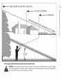
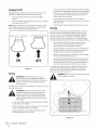
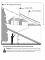
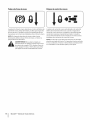
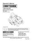
Sight and hold this level with a vertical tree...
or a corner of a building...
I
I
|
|
|
|
Iv
Z
0
0
|
|
!-Z
Q.
I
¢N
Z
0
m
In
!
|
15 °
Usethis page as a guide to determine slopeswhere you may not operate safely.
WARNING:
Do not operate
(a rise of approximately
mowers
up and down
your lawn mower
on such slopes. Do not mow on inclines with a slope in excess of 15 degrees
2-1/2 feet every 10 feet).
A riding
mower
slopes, never across the face of slopes.
could
overturn
and cause serious injury. Operate
riding
3
Assembly& Set-Up
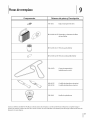
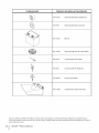
Contents of Crate
One Lawn Tractor
One Oil Drain Tube
One Deck Wash Hose Coupler
One Lawn Tractor Operator's
Manual
One Kohler Engine Operator's
Manual
One Product
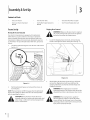
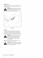
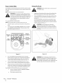
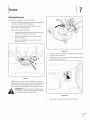
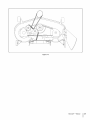
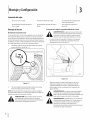
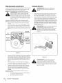
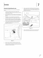
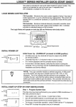
Moving The TractorManually
transmission
relief valve for occasions
tractor
manually.
is equipped
with a hydrostatic
when it is necessary
Opening
this valve permits
Locate the hydrostatic
off, set the parking brake and remove the ignition
Make sure
lawn tractor's
keyARNING!
before removing
the the
shipping
brace. engine is
_
to move the
the fluid in the
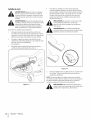
Locate the shipping brace, if present, and warning tag
found on the right side of the cutting deck. See Fig. 3-2.
transmission
to bypass its normal route, allowing the rear tires
to "freewheel."
To open the hydrostatic
relief valve, proceed as
follows:
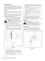
1.
Card
Shipping BraceRemoval
Tractor Set-Up
Your tractor's
Registration
bypass rod in the rear of the tractor.
See Fig. 3-1.
Figure
2.
2.
Pull the hydrostatic
lock it in place.
bypass rod outward,
the discharge
the shipping
grasping it between
rotating it clockwise.
then down, to
NOTE:The transmission
will NOTengage
when the hydrostatic
bypass rod is pulled out. Return the rod to its normal position
prior to operating
While holding
remove
Figure 3-1
packaging
3-2
chute with your left hand,
brace with your right
your thumb
purposes
hand by
and index finger
and
only. Remove and discard the
is usedlawn
for tractor.
your
_
WARNING!
Thebefore
shipping
brace
shipping brace
operating
_
throwing
objects. Failure to operate the riding
ARNING!
mowing
deckcover
is capable
mower
withoutThethe
discharge
in the of
proper
the tractor.
CAUTION:
manually
Never attempt
without
to move the tractor
first opening
the hydrostatic
valve. Doing so will result in serious damage
tractor's transmission.
relief
to the
operating
position
injury and/or
could result in serious personal
property
damage.
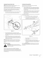
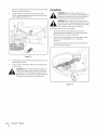
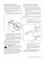
Attaching the Negative Battery Cable
NOTE:The
negative
positive
battery
The positive
battery
battery
terminal
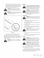
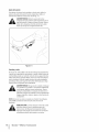
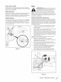
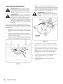
Setting the DeckGaugeWheels
terminal
is marked
is marked
Neg. (-).
cable (heavy red wire) is secured
terminal
Pos. (+). The
pavement,
to the positive
cable (heavy black wire) may be secured to
the negative
battery
I.
I.
(+) with a hex bolt and hex nut at the factory.
The negative
attached,
Move the tractor
proceed
terminal
at the factory.
If it hasn't been
hood and remove the carriage
position
of the cutting
setting (any of the six different
the right fender).
2.
hex nut from the negative
Select the height
as follows
the deck lift lever in the normally
as follows:
Raise the tractor's
on a firm and level surface, preferably
and proceed
Check the gauge wheels
deck by placing
desired
cutting
for contact
mowing
height
height notches
on
or excessive cleara nce
with the surface below. The deck gauge wheels should
have between I/4-inch and I/2-inch clearance above the
bolt and
cable (heavy black wire).
ground
as follows:
If the gauge wheels
have excessive clearance
or contact
with the
surface, adjust as follows:
a.
Raise the deck lift handle to its highest
b.
Remove the front and rear gauge wheels by
removing the lock nuts and shoulder screws which
setting.
secure them to the deck. See Fig. 3-4
Figure
2.
Remove the black plastic
3-3
cover, if present, from the
negative battery terminal and attach the negative cable to
the negative battery terminal (-) with the bolt and hex nut.
See Fig. 3-3.
3.
Make certain the hold-down
battery,
securing
rod is in position
rubber boot covers the positive
protect it from corrosion.
NOTE: If the battery
Figure 3-4
over the
it in place and make certain that the red
battery
terminal
to help
c.
is put into service after the date shown
d.
Refer to Leveling
circumstances is 30 psi. Equal tire pressure should
WARNING!
maintained
atMaximum
all times. tire pressure under any
Reduce the tire pressure before
screw(with
each gauge
pavement.
manual
purposes.
Reinsert the shoulder
wheel) into the index hole that leaves approximately
1/2-inch between the bottom of the wheel and the
CheckingTire Pressure
The tires on your unit may be over-inflated
mowing
height setting.
on top/side of battery, charge the battery as instructed in the
Maintenance
section of this manual prior to operating the
tractor.
i_
Place the deck lift lever in the desired
be
the Deck in the Maintenance
for more detailed
instructions
regarding
section
of this
various deck
adjustments.
for shipping
operating
the tractor.
Recommended
operating tire pressure is approximately
10 p.s.i.
for the rear tires & 14 p.s.i, for the front tires. Check sidewall of tire
for maximum
p.s.i.
SECTION
2 --
ASSEMBLY& SET-UP
9
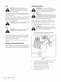
Adjusting the Seat
To adjust the position
seat adjustment
rearward.
of the seat forward
or backward,
move the
lever to the left and slide the seat forward
or
See Fig. 3-5.
WARNING!
Before operating
the seat is engaged
parking
the tractor,
in the seat-stop.
make sure
Engage the
brake. Stand behind the machine
and pull
back on seat until it clicks into place.
\
\
Figure 3-5
Gasand Oil
The fuel tank is located
of three and-a-half
under the fender
and has a capacity
gallons. Remove the fuel cap by turning
it
counterclockwise.
Use only clean, fresh (no more than 30 days
old), unleaded gasoline. Fill the tank no higher than four inches
below the top of the filler neck to allow
space for fuel expansion.
gasoline. Gasoline is extremely
flammable and the
ARNING!
Use extreme
handling
vapors
are explosive.
Nevercare
fuel when
the machine
_IL
--
indoors or while the engine is hot or running.
Extinguish cigarettes, cigars, pipes and other
sources of ignition.
NOTE:Your
tractor
is shipped
with oil in the engine.
you MUST check the oil level before
each use as instructed
_
However,
operating.
in the Kohler Owner's
Manual.
AUTION:
Always check
oil level
Add
oil as necessary.
Failuretheto engine
do so may
resultbefore
in
serious damage to your engine
SECTION
2
--
ASSEMBLY&
SET-UP
4
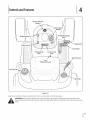
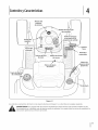
Controls
and Features
F
Systems indicator
Monitor
ignition Switch
Module
Throttle Control
Brake Pedal
Choke Control
Drive Pedal
Parking Brake
Lever
Cruise Control
Lever
i
Deck Lift Lever
Seat
'
"...... Adjustment
Lever
"
Fuel Tank Cap
Holder
J
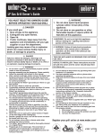
Figure 4-1
Lawn Tractor controls
and features are illustrated
before attempting
to operate
WARNING!
Read and follow
injury.
in Fig 4-1 and described
on the following
pages.
this machine. Failure to comply with all safety rules and instructions
may result in personal
all safety rules and instructions
in this manual, including the entire Operation section,
11
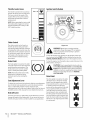
ThrottleControl Lever
The throttle
control
lever is located
the left side of the tractor's
This lever controls
on
dash panel.
the speed of the
engine. When set in a given position,
the throttle will maintain a uniform
engine speed.
NOTE:When
the cutting
operating
the tractor
deck engaged,
that the throttle
Normal
Driving
Mode
with
be certain
lever is always in the
FAST (rabbit) position.
Start
Position
ChokeControl
The choke control
,J
can be found
on
Figure 4=2
the left side of the dash panel and is
activated
by pulling
Activating
the knob outward.
the choke control
closes the
_lllL
choke plate on the carburetor and aids
in starting the engine. Refer to Starting
The Engine in the Operation
of this manual
instructions.
for detailed
section
unattended.
Always disengage PTO, set parking
ARNING!
Never and
leaveremove
a running
machine
brake,
stop engine
key to
prevent
unintended
starting.
To start the engine,
starting
8rake Pedal
To stop the engine, turn the ignition
STOP position. See Fig. 4-2.
The brake pedal is located on the right
front side of the tractor above the drive
CAUTION:
pedal along the running
both Safety Interlock
board. The
NOTE:The
depressed
interlock
tractor.
starting
board.
Assembly
position
is found,
release the seat
lever to lock the seat in place. Refer to the Set-Up and
section of this manual for more detailed
instructions.
change
Press the upper portion
portion
of the drive pedal with the ball
of your right foot (NOT your heel) to
cause the tractor to travel in reverse.
speed is also controlled
the drive pedal. The further
right fender, the deck lift lever is used to
the height of the cutting
deck. To use, move the lever to
the left, then place in the notch best suited for your application.
SECTION 4--
CONTROLS AND FEATURES
with
forward
or
rearward that the pedal is pivoted, the
faster the tractor will travel. The pedal
will return to its original
it's not pressed.
I
of the
drive pedal forward to cause the tractor
to travel forward. Press the lower
Ground
DeckLift Lever
Found on your tractor's
section
The drive pedal is located on the right
side of the tractor, along the running
To adjust the seat forward or backward, slide the seat adjustment
lever to the left and reposition the seat to the desired position.
adjustment
the tractor,
Switches
DrivePedal
the
SeatAdjustmentLever
Once a comfortable
Prior to operating
to the
refer to
and Starting
of this manual
The
for
detailed instructions
regarding the Ignition Switch
Module and operating the tractor in REVERSE
CAUTION MODE.
brake pedal must be fully
to activate the safety
switch when
switch and
key counterclockwise
Engine in the Operation
brake pedal can be used for sudden
stops or setting the parking brake.
12
insert the key into the ignition
turn clockwise to the START position. Release the key into the
NORMAL MOWING MODE position once the engine has fired.
position
when
Brake
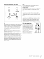
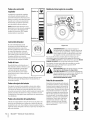
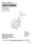
SystemsindicatorMonitor/Hour Meter
If the Brake light illuminates when attempting to start the
tractor's engine, depress the brake pedal.
©
©
BATT.
OIL
PTO(Blade Engage)
If the PTOlight illuminates when attempting to start the tractor's
engine, move PTOlever into the disengaged (OFF)position.
//J
/ j
i
///
j
jf_J
It is normal for the Oil light to illuminate while the engine is
cranking during start-up, but if it illuminate's during operation,
while the engine is running, stop the tractor immediately and
check the engine oil level as instructed in this Owner's Manual.
42.0
HOURS
1//10 \\\
cO)
/
PTO / BLADE
Oil
PARKING
©
LCD
When the ignition key is rotated out of the STOP position but not
into the STARTposition, the systems indicator monitor displays
the battery's output, in volts, on its LCDfor approximately five
seconds, after which it displays an hour glass and the hours
of tractor operation. Once the tractor is started, the monitor
continually displays an hour glass and the hours of tractor
operation on its LCD.
NOTE: Hours of tractor operation are recorded any time the
ignition key is rotated out of the STOPposition, regardless of
whether the engine is started.
The Indicator Monitor will also remind the operator of
maintenance intervals for changing the engine oil. The LCD will
alternately flash the recorded hours, "CHG" and "OIL" for five
minutes, after every 50 hours of recorded operation elapse. The
maintenance interval lasts for two hours (from 50-52,100-102,
150-152, etc.). The LCDwill also flash as described above for five
minutes every time the tractor's engine has been started during
this maintenance interval. Before the interval expires, change
the engine oil as instructed in the Maintenance section of this
Operator's Manual.
Battery
It is normal for the Battery light to illuminate while the engine is
cranking during start-up, but if it illuminate's during operation,
while the engine is running, the battery is in need of a charge
or the engine's charging system is not generating sufficient
amperage. Charge the battery as instructed in the Service
section of this manual or have the charging system checked by
your Cub Cadet dealer.
PTO/ Blade EngageKnob
Activating
the PTO engages
PTO
power to
the cutting deck or other (separately
available) attachments.
Pull outward
on the PTO/Blade Engage knob to
activate
it. Push the PTO/Blade
knob inward to disengage
Engage
the power
to the cutting deck or other (separately
available) attachments.
NOTE:The PTO/Blade Engage knob
must be in the disengaged
(OFF)
position
when starting
OFF
ON
the engine.
SECTION
4
--
CONTROLS AND
FEATURES
13
CruiseControl Lever
ParkingBrakeLever
J
Located
in the center of the tractor's
steering
wheel, the parking
parking
brake. Refer to the Operation
detailed
instructions
NOTE:The
parking
brake lever is used to engage
regarding
running
the parking
brake.
dash panel. Engaging
remain at a constant
detailed
instructions
NOTE: Cruise control
fastest ground
Never leave a running
unattended.
Always disengage
brake, stop engine and remove
unintended
starting.
CONTROLS AND FEATURES
lever is located
in the center of the tractor's
the cruise control
ground
machine
PTO, set parking
key to prevent
the tractor
mowing
regarding
section
can NOT be engaged
speed
applying
should
decelerate
to
pressure to
of this manual
the cruise control
speed. If the operator
will automatically
ground
allows the tractor
speed without
the drive pedal. Refer to the Operation
leaves the
or the engine will automatically
WARNING!
SECTION 4--
the
section of this manual for
brake must be set if the operator
seat with the engine
shut off.
The cruise control
dash panel below the
feature.
at the tractor's
attempt
to do so,
to the fastest optimal
for
Operation
Starting the Engine
TO AVOID SERIOUS INJURY OR DEATH
•
•
•
•
GOUP ANDDOWNSLOPES,NOTACROSS.
AVOIDSUDDENTURNS.
DONOTOPERATE
THEUNITWHEREIT COULDSLIPORTIP.
IF MACHINESTOPSGOINGUPHILL,STOPBLADE(S)
ANDBACKDOWNHILLSLOWLY.
• KEEPSAFETYDEVICES(GUARDS,SHIELDS,AND
SWITCHES,ETC.) IN PLACEANDWORKING.
• REMOVE
OBJECTS
THATCOULD
BETHROWN
BYTHEBLADE(S).
• KNOWLOCATIONANDFUNCTIONOFALLCONTROLS.
• BESUREBLADE(S)ANDENGINEARESTOPPEDBEFORE
PLACINGHANDSORFEET NEARBLADE(S).
• BEFORELEAVINGOPERATOR'S
POSITION,DISENGAGE
BLADE(S),ENGAGEPARKINGBRAKE,SHUTOFFAND
REMOVEKEY.
READ OPERATOR'S MANUAL
This tractor
is equipped
for Gasoline
system for the
Insert the tractor
2.
Place the PTO (Blade Engage) knob in the disengaged
engaging
shut off if the operator
the parking
3.
Engage the tractor's
4.
Activate
5.
Turn the ignition
of whether
the parking
parking
(OFF)
brake.
the choke control.
key clockwise
to the START position.
position for longer than ten seconds at a time.
AUTION:
NOT damage
hold the tokey
in the
START
Doing
so mayDocause
your
engine's
electric starter.
After the engine
starts, deactivate
tractor.
the choke control.
on while
Doing so will result in a "rich" fuel mixture
operating
the
and cause the
engine to run poorly.
engine
and disconnect
_
Thoroughly
ARNING!
1.
If the blades are engaged,
the spark plug wire(s).
inspect
If you strike
the machine
a foreign forobject,
any damage.
stop the
Repair the damage
knob in the disengaged
The electric PTO (Blade Engage) clutch will automatically
shut off if the operator leaves the tractor's seat with the
regardless
module.
After the engine starts, release the key. It will return to the
NORMAL MOWING position.
leaves
brake.
PTO (Blade Engage) knob in the engaged
switch
Stopping the Engine
the engine from
(OFF) position.
the seat before
key into the ignition
position.
cranking or starting unless the parking brake is engaged,
and the PTO (Blade Engage) knob is in the disengaged
The engine will automatically
section of this manual
instructions.
NOTE: Do NOT leave the choke control
protection
of the operator. If the interlock system should ever
malfunction,
do not operate the tractor. Contact your Cub Cadet
dealer.
system prevents
and Oil fill-up
1.
6.
with a safety interlock
The safety interlock
NOTE: Refer to the Set-Up and Assembly
_
Safety InterlockSwitches
interlock system is malfunctioning.
This system was
ARNING!for your
Do not
operate
tractor if the
designed
safety
and the
protection.
__,
before
restarting
and operating
place the PTO/Blade Engage
(OFF) position.
2.
Place the throttle
control
3.
Turn the ignition
key counterclockwise
near the SLOW position
(ON) position,
brake is engaged.
to the STOP
position.
With the ignition
key in the NORMAL MOWING position,
the electric PTO (Blade Engage) clutch will automatically
shut off if the PTO (Blade Engage) knob is moved into the
engaged (ON) position
Reverse travel.
with the drive pedal in position
4.
Remove the key from the ignition
unintended
switch to prevent
starting.
for
interlock system is malfunctioning.
This system was
WARNING!
Do not
operate
tractor if the
designed for your
safety
and the
protection.
15
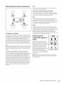
ReverseCaution Mode
Driving TheTractor
The REVERSE CAUTION MODE position of the key switch module
allows the tractor to be operated in reverse with the blades (PTO)
engaged.
_
NOTE:Mowing
the tractor
Use extreme
caution
while
operating
1.
in the REVERSE CAUTION MODE. Always
look down and behind
not operate the tractor
before and while backing. Do
when children or others are
around. Stop the tractor
enters the area.
immediately
2.
if someone
To use the REVERSECAUTION MODE:
1.
2.
stops.
Avoid sudden
starts, excessive
speed
in reverse is not recommended.
WARNING!
NOTE:The
and sudden
ARNING!
operator
MUST be seated in the tractor
Start the engine as previously
instructed
seat.
Lightly press the brake pedal to release the parking brake.
Move the throttle lever into the FAST(rabbit) position.
To travel FORWARD,slowly press the upper portion of the
drive pedal forward until the desired speed is achieved.
See Fig. 5-2.
To travel in REVERSE,check that the area behind is clear
then slowly depress the lower portion of the drive pedal
with the ball of your foot (NOT your heel) until the desired
speed is achieved. SeeFig. 5-2.
on the previous
page.
direction
Turn the key from the NORMAL MOWING (Green) position
CAUTION:
attempt
to change stop
the before
Always
bring Do
the NOT
tractor
to a complete
to the REVERSECAUTION MODE (Yellow)
pivoting the drive pedal from forward
vice versa.
key switch module.
position
of the
See Fig. 5-1.
of travel when the tractor
is in motion.
to reverse or
\
Indicator
NO CHILDREN
AROUND
Push Button
REVERSE PUSH
Light
BUTTON
* ii
Stop
Position
\4
Reverse
Reverse
Caution Mode
Position
\
\
/
/
Position
Start
Figure 5-2
Figure 5-1
3.
Press the REVERSE PUSH BUTTON (Orange, Triangular
Button) at the top, right corner of the key switch module.
The red indicator light at the top, left corner of the key
switch
4.
module
Once activated
will be ON while
(indicator
See Fig. 5-1.
light ON), the tractor
driven in reverse with the cutting
5.
activated.
can be
blades (PTO) engaged.
Always look down and behind before and while backing to
make sure no children are around. After resuming forward
motion,
return the key to the NORMAL MOWING position.
The REVERSE CAUTION MODE will remain activated
a.
The key is placed
position
b.
SECTION
The operator
S--
in either
or STOP position
OPERATION
until:
the NORMAL MOWING
or
leaves the seat.
without
_
first placing
the PTO/Blade Engage knob in
theARNING!
disengagedDo (OFF)
not leave
position
the seat
and of
engaging
the tractor
the
parking
brake. If leaving the tractor
unattended,
turn the engine off and remove the ignition
key.
also
Driving OnSlopes
Setting TheCruiseControl
Refer to the SLOPE GAUGE on page 7 to help determine
where you may operate
the tractor
slopes
safely.
while
_i
excess of 15 degrees (a rise of approximately
2-1/2
WARNING!
Do notThe
mow
on inclines
with a slope
feet
every 10 feet).
tractor
could overturn
and in
i_ll
cause serious injury.
Mow up and down
Exercise extreme
1.
when changing
direction
rocks, or other
objects. Uneven terrain could overturn
grass can hide obstacles.
Avoid turns when driving
on
hidden
the machine.
Tall
on a slope. Ira turn must be
made, turn down the slope. Turning
increases the chance of a roll over.
Slowly press the upper
up a slope greatly
parking
Remove your foot from the drive pedal.
4.
Release pressure from the cruise control
running
lever downward
speed. If it doesn't,
the cruise control
1.
To disengage the cruise control,
the brake pedal.
NOTE: Cruise control
lightly
brake:
will automatically
should attempt
decelerate
Push the parking
down with your right foot
brake lever downward
and hold it in that
position.
to the fastest optimal
To change the direction of travel from forward to reverse when
cruise control is engaged, press the brake pedal to disengage
Remove your foot from the brake pedal.
4.
Release pressure from the parking
brake lever.
After completing
step 3, the brake pedal should remain in the
clown position. If it doesn't, the parking brake is not engaged.
Repeat steps 1-4 to engage the parking
brake.
To disengage
press the brake pedal.
the parking
unattended.
i_
brake, lightly
to a complete
stop. Then
of the drive pedal with the ball of
your foot to travel in reverse.
Usingthe DeckLift Lever
To raise the cutting
3.
fastest
to do so, the
speed.
slowly press the rear portion
and hold it in that position.
2.
Repeat
press the drive pedal or
can not be set at the tractor's
speed. If the operator
ground
is not engaged.
leaves the
or the engine will automatically
Press the brake pedal completely
lever
the cruise control.
the cruise control and bring the tractor
To set the parking
and hold it
After completing
step 3, the drive pedal should remain in the
down position and the tractor will maintain the same forward
tractor
brake must be set if the operator
of the drive pedal with your
3.
mowing
seat with the engine
shut off.
lever
speed is achieved.
Lightly press the cruise control
in that position.
ground
Engaging the ParkingBrake
the cruise control
2.
steps 1-4 to engage
Avoid stopping when driving up a slope. If it is necessary
to stop while driving up a slope, start up smoothly and
carefully to reduce the possibility of flipping the tractor
over backward.
NOTE:The
portion
right foot until the desired
slopes.
Watch for holes, ruts, bumps,
in reverse.
Never engage
To set the cruise control:
slopes, NEVER across.
caution
traveling
ARNING!
deck, move the deck lift lever to the left, then
place it in the notch best suited for your application.
Operating the Headlights
The lamps are ON whenever
the ignition
key is rotated
out of
the STOP position. The lamps turn OFF when the ignition
moved to the STOP position.
key is
Always disengage PTO, set parking
leaveremove
a running
machine
and
key to
prevent
WARNING!
Never
brake, stop engine
unintended
starting
SECTION
S --
OPERATION
17
For best results it is recommended
Engagingthe PTO
Engaging
the PTO transfers
(separately
1.
cut with the discharge
available)
power to the cutting
attachments.
Move the throttle
control
deck or other
To engage the PTO:
better
lever to the FAST (rabbit)
appearance
Do NOT attempt
Pull the PTO/Blade Engage knob outward
(ON) position.
See Fig. 5-3.
available)
the center. After the
to the lawn.
to mow heavy brush and weeds or
extremely tall grass. Your tractor
NOT clear brush.
into the engaged
is designed
to mow lawns,
Keep the blades sharp and replace the blades when worn.
NOTE:Always operate the tractor with the throttle lever in the
FAST (rabbit) position for the most efficient use of the cutting
deck or other (separately
that the first two laps be
towards
first two laps, reverse the direction to throw the discharge
to the outside for the balance of cutting. This will give a
position.
2.
thrown
Mulching
attachments.
Cub Cadet Series 1000 tractors
which
._.J
incorporates
are equipped
special blades, already
with a mulch
standard
kit
on your
tractor, in a process of recirculating
grass clippings repeatedly
beneath the cutting deck. The ultra-fine clippings are then
forced back into the lawn where they act as a natural fertilizer.
Observe the following
Never attempt
points
for the best results when
mulching.
to mulch if the lawn is damp. Wet grass
tends to stick to the underside of the cutting deck
preventing
proper mulching of the clippings.
Do NOT attempt
to mulch
more than 1/3the total height
the grass. Doing so will cause the clippings
beneath
the deck and not be mulched
Maintain
a slow ground
more time to effectively
Always keep the throttle
OFF
mowing.
Figure 5-3
of
up
effectively.
speed to allow the grass clippings
be mulched.
control
lever in the FAST (rabbit)
position
while
Failing to keep the engine at full
throttle
places strain on the tractor's
allow the blades to properly
J
to clump
engine and does not
mulch the grass clippings.
To operate the cutting deck without mulching, simply remove
the mulch plug by unthreading
the plastic wing nut which
fastens it to the cutting
discharge
deck. This will allow the clippings
to
out the side. See Fig. 5-4.
Mowing
WARNING!
To help avoid blade contact
or a
thrown object injury, keep bystanders, helpers,
children and pets at least 75 feet from the machine
while it is in operation.
enters the area.
The following
information
Stop machine
will be helpful
when
_
while the engine is running.
ARNING!
Never install or remove the mulch
if anyone
using the cutting
deck with your tractor.
discharge of materials toward roads, sidewalks,
WARNING!
Plan
pattern
to avoid
bystanders and
theyour
like.mowing
Also, avoid
discharging
i_
material
against
cause discharged
a wall or obstruction
material
to ricochet
which
may
back toward
the operator.
Do not mowat
or grass collector
high ground
speed, especially
ira mulch kit
is installed.
Do not cut the grass too short. Short grass is prone
growth
and yellows
quickly
to weed
in dry weather.
Always operate the tractor with the throttle
FAST (rabbit) position while mowing
lever in the
Figure 5-4
SECTION
S--
OPERATION
plug
6
Maintenance& Adjustments
Maintenance
WARNING!
Before performing
repairs, disengage
any maintenance
PTO, set parking
engine and remove key to prevent
starting.
4.
Remove the oil fill cap/dipstick
from the oil fill tube.
5.
Push the oil drain hose (packed
with this manual)
or
brake, stop
unintended
capacity,
6.
to collect
procedures
NOTE: Maintenance,
control
Manual
for all engine
maintenance
7.
and instructions.
repair, or replacement
After the oil has finished draining, push the end of the oil
drain valve back in, until the tabs click into place. Re-cap
the drain port.
expense may be performed
by any engine repair establishment
or individual. Warranty repairs must be performed
by a Cub
Cadet Dealer.
8.
Replace the oil filter as instructed
Manual.
9.
Refill the engine with new oil. Refer to the Kohler Owner's
Manual
Changingthe Engine Oil
for information
of engine
WARNING!
If the engine has been recently run, the
engine, muffler and surrounding
metal surfaces will
be hot and can cause burns to the skin. Exercise
NOTE:The
interval.
1.
to avoid burns.
oil filter should
To complete
be changed
an oil change,
Run the engine for a few minutes
crankcase
at every oil change
proceed
as
be cleaned
and the gap reset once a
Manual
for correct
plug type
Hydrostatic Transmission
hood and locate the oil drain port on the
The hydrostatic transmission
maintenance-free.
The fluid
fluid cannot
Pop open the protective
cap on the end of the oil drain
is sealed at the factory and is
level cannot be checked and the
be changed.
Battery
valve to expose the drain port. See Fig 6-1.
\\\
Service the pre-cleaner and cartridge/air
cleaner element
instructed
in the Kohler Owner's Manual.
and gap specifications.
left side of the engine.
3.
and weight
Air Cleaner
season. Refer to the Kohler Owner's
hot oil.
Open the tractor's
the volume
oil
The spark plug should
to allow the oil in the
carry away more of the engine sediment which may have
settled at the bottom of the crankcase. Use care to avoid
2.
regarding
in the Kohler Owner's
SparkPlug
as follows:
to warm up. Warm oil will flow more freely and
burns from
to
oil. See Fig 6-1.
the end of the oil drain valve to keep debris from entering
of the emission
devices and systems which are being done at owner's
caution
the used oil.
Pinch the tabs on the oil drain valve, then pull outward
begin draining
Refer to the Kohler Owner's
onto the
oil drain port. Route the opposite end of the hose into an
appropriate
oil collection container with at least a 2.5 quart
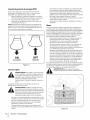
Battery posts, terminals, and related accessories
CALIFORNIA
WARNING! known
contain lead andPROPOSITION
lead compounds, 65 chemicals
to the State of California to cause cancer and
•
j.o
ii
reproductive
/
harm. Wash hands after handling.
The battery is sealed and is maintenance-free.
be checked and fluid can not be added.
Acid levels cannot
Always keep the battery cables and terminals
free of corrosive build-up.
After cleaning
of petroleum
the battery
and terminals,
clean and
apply a light coat
jelly or grease to both terminals.
disconnect
the NEGATIVE (Black) wire from it's
CAUTION:
removing bythethebattery
for cleaning,
terminal
first, If followed
POSITIVE
(Red) wire.
When re-installing
the battery, always connect the
POSITIVE (Red) wire its terminal first, followed by the
NEGATIVE (Black) wire. Be certain that the wires are
connected
J
to the correct
terminals;
reversing
them
could result in serious damage to your engine's
alternating
system.
Figure 6-1
19
8.
Cleaningthe Tractor
Any fuel or oil spilled
on the machine
should
be wiped
off
especially
9.
the belts and pulleys.
10.
TM
deck is equipped
with a water port on its surface as
11.
part of its deck wash system.
Drive the tractor
enough
from the deck's
12.
the buildup of corrosive chemicals.
steps AFTER EACH MOWING:
to a level, clear spot on your lawn, near
for your garden
Turn the ignition
hose to reach.
the PTO (Blade Engage), set the parking
After cleaning
the operator's
Operator's
4.
(packaged
key to the STOP position
to turn the
the hose coupler
from the
side of the cutting
your deck with the Smart Jet TM system, return to
position and engage the PTO. Keep the cutting
for a minimum
of two minutes,
deck to thoroughly
allowing
the
dry.
Lubrication
with your tractor's
Manual) onto the end of your garden
Attach the hose coupler
surface. See Fig. 6-2.
rinse.
off.
of the cutting
_i
Thread the hose coupler
the
PTO (Blade Engage) into the OFF
Repeat step 4- step 11 on the opposite
deck.
brake
and stop the engine.
3.
engine
deck running
chute is directed AWAY from your house, garage,
CAUTION:
certain the tractor's discharge
parked cars, Make
etc.
Disengage
deck
allowing
deck to thoroughly
Turn the water off and detach
underside
2.
with the cutting
water port on your deck's surface.
Use the Smart Jet TM to rinse grass clippings
and prevent
the following
of the cutting
Move the tractor's
tractor's
Your tractor's
1.
of two minutes,
for a minimum
position.
Snlart Jet
underside
Complete
position
engaged
underside
promptly. Do NOT allow debris to accumulate around the cooling
fins of the engine, the transmission's
cooling fan or on any other
part of the machine,
Remain in the operator's
inspecting,
always disengage PTO, set parking
ARNING!
Before and
lubricating,
repairing,
or
brake,
stop engine
remove key
to prevent
unintended
starting.
FrontWheels
hose.
to the water port on your decks
Each of the front wheel axles and rims is equipped
grease fitting.
grease applied
See Fig. 6-3. Lubricate
with a
with a No. 2 multi-purpose
with a grease gun after every 25 hours of tractor
operation.
\
jr ............L
..............................................................
..........................................
i_:;::
.............
/
()
/
/
Figure 6-2
5_
Turn the water on.
6.
While sitting
the engine
J
Figure 6-3
in the operator's
position
and place the throttle
on the tractor,
lever in the FAST (rabbit)
position.
7_
Move the tractor's
position.
SECTION 6 --
PTO (Blade Engage) into the ON
MAINTENANCE
start
& ADJUSTMENTS
PivotPoints& Linkage
Lubricate
Adjustments
all the pivot points
on the drive system, parking
brake
WARNING!
and lift linkage at least once a season with light oil.
ignition
DeckWheels
off, remove the
the parking
brake before
making adjustments.
Protect your hands by using
heavy gloves when handling the blades.
Each of the tractor
a grease fitting.
Shut the engine
key and engage
deck's front gauge wheels
Lubricate
is equipped
with a No. 2 multi-purpose
with
grease
NOTE: Check the tractor's
tire pressure before
performing
applied with a grease gun after every 25 hours of tractor
operation
any deck leveling adjustments.
Refer to Tires on page 25 for
information
regarding tire pressure.
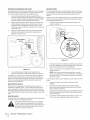
DeckSpindle
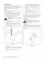
Levelingthe Deck(Front ToRear)
Grease fittings can be found on each deck spindle. See Fig. 6-4.
Lubricate with 251H EP grease or an equivalent
No. 2 multi-
The front of the cutting
purpose lithium grease. Using a grease gun, apply two strokes
(minimum) or sufficient grease to the spindle shaft.
can be adjusted
the deck should
rear of the deck. Adjust
1.
\
deck is supported
by a stabilizer
bar that
to level the deck from front to rear. The front of
be between 1/4-inch and %-inch lower than the
Park the tractor
if necessary
as follows:
parked on a firm, level surface and place
the deck lift lever in the top notch.
2.
Rotate the blade nearest the discharge
parallel with the tractor.
chute so that it is
3.
Measure the distance from the front of the blade tip to the
ground and the rear of the blade tip to the ground. The
first measurement
taken should be between 1/4-inch and
%-inch less than the second measurement.
Determine
the approximate
adjustment
and proceed,
1.
Loosen (thread
deck hanger
distance
necessary
for proper
if necessary.
outward)
the hex lock nut on the end of the
rod. See Fig. 6-5.
2a.
To raise the front of the deck, tighten (thread inward)
inner hex nut against the front hanger bracket.
2b.
To lower the front of the deck, loosen (thread
hex nut, away from the front
3.
Retighten
adjustment
hanger
the
outward)
the
bracket. See Fig. 6-5.
the lock nut against the hex nut when
proper
is achieved.
Figure 6-4
\
J
Figure 6-5
SECTION 6 --
MAINTENANCE
& ADJUSTMENTS
21
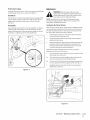
Leveling the Deck(Sideto Side)
if the cutting
adjustment
deck appears
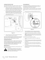
Steering Adjustment
to be mowing
can be performed.
Adjust
unevenly, a side to side
if necessary as follows:
the ball joints
With the tractor parked on a firm, level surface, place the
deck lift lever in the top notch (highest position) and rotate
1.
both blades so that they are perpendicular
Measure the distance from the outside
2.
tip to the ground
should
be equal. If they're
Loosen,
hanger
with the tractor.
of the left blade
and the distance from the outside
right blade tip to the ground.
Both measurements
not, proceed
If the tractor
of the
steering
turns tighter
in one direction
are being replaced
or wear, the
drag links may need to be adjusted.
Adjust the drag links so that equal lengths
into the ball joint
side:
1.
than the other, or if
due to damage
of each are threaded
on the left side and the ball joint
on the right
Remove the hex nut on the top of ball joint.
See Fig. 6-7.
taken
to the next step.
but do NOT remove, the hex bolt on the left deck
bracket.
See Fig. 6-6.
J
Figure 6-7
2.
Figure 6-6
4.
3.
leveled when
taken earlier are equal. Retighten
hanger
bracket
when
both blade tip measurements
the hex bolt on the left deck
proper adjustment
is achieved.
ParkingBrakeAdjustment
If the tractor
pedal is completely
depressed,
or if the tractor's
Cadet dealer to have the brake properly
rear wheels
can
Refer to the Set-Up and Assembly
section of this manual for seat
instructions.
Warning! Before operating
the tractor, make sure
the seat is engaged in the seat-stop. Engage the
parking
brake. Stand behind the machine
back on seat until it clicks into place.
SECTION 6 --
MAINTENANCE
& ADJUSTMENTS
and pull
to shorten
the drag link.
to lengthen
the drag link.
Replace the hex nut after proper adjustment
is achieved.
can be measured
Place the steering
travel.
as follows:
wheel in position
for straight
ahead
In front of the axle, measure the distance horizontally
from
the inside of the left rim to the inside of the right rim. Note
the distance.
3.
Behind the axle, measure the distance horizontally
from
the inside of the left rim to the inside of the right rim. Note
the distance.
4.
The measurement
adjusted.
Adjusting the Seat
adjustment
1.
stop when the brake
roll with the parking brake applied (and the hydrostatic relief
valve open), the brake is in need of adjustment.
See your Cub
outward
Front tire toe-in
2.
does not come to a complete
inward
Thread the ball joint
NOTE:Threading
the ball joints too far onto the drag links
will cause the front tires to "toe-in" too far. Proper toe-in is
between 1/16" and 5/16".
Using a wrench, raise or lower the left side of the deck by
turning the adjustment
gear. See Fig. 6-6.
The deck is properly
Thread the ball joint
taken in front of the axle should
between 1/16" and 5/16" less than the measurement
behind the axle.
be
taken
MaintenanceSchedule
Before
Eachuse
Every
I0 Hours
Every
25 Hours
Every
50 Hours
Every
I00 Hours
,/
,/
CleanHood/DashLouvers
CheckEngineOil Level
_"
CheckAir Filterfor Dirty,Looseor DamagedParts
_"
CleanandRe-oilAir Filter'sFoamPredeaner
Prior
toStoring
_"
ReplaceAir Filter Element
ChangeEngineOiland ReplaceOil Filter
CleanBattery Terminals
_"
V/
V/
LubeFrontAxlesand Rims
_
CleanEngineCoolingFins
_
LubeFrontDeckWheels
V/
LubeDeckSpindles
_
LubePedalPivot Points
V/
_
CheckSparkPlug Condition&Gap
_"
ReplaceFuelFilter
_"
SECTION 6 --
MAINTENANCE
_"
& ADJUSTMENTS
23
Maintenance Log
Please keep a record of the maintenance
Date
SECTION 6 --
performed
HourMeter
MAINTENANCE
& ADJUSTMENTS
on your tractor.
Maintenance
PerformedBy
7
Service
Cutting DeckRemoval
To remove the cutting
1.
2.
as follows:
Engage knob in the disengaged
position
the parking
and engage
Lower the deck by moving
bottom
3.
deck, proceed
Place the PTO/Blade
(OFF)
brake.
the deck lift lever into the
notch on the right fender.
Remove the deck belt. See Fig 7-1..
a.
Unthread
the self-tapping
screw which
belt keeper rod to the tractor's
secures the
frame
b.
Removng the belt keeper rod from
electric PTO clutch.
around
c.
Remove the deck belt from around
the tractor's
electric
the
PTO clutch.
Figure 7-2
/ ©
Looking
at the cutting
deck from the left side of the tractor,
locate the deck support
Pull the deck support
pin.
pin outward
to release the deck from
the deck lift arm. See Fig. 7-3.
/,,
//
/
// /
,,
....,
/"
©
J
Figure 7-1
Note:
If there is too much tension
easily removed
the left-hand
tractor's
i_ll
from the electric
on the belt for it to be
PTO clutch, carefully
deck idler pulley and pivot it toward
left side to relieve tension
grasp
the
on the belt. See Fig. 7-2
your fingers on the idler spring or between the belt
WARNING?
Avoid removing
pinching the
injuries.
and a pulley while
belt. Never place
f,'
_
/'/
/ ...............\
Figure 7-3
6.
Repeat step 4 and step 5 on the tractor's
right side.
25
7.
Move the deck lift lever into the top notch to raise the deck
lift arms up and out of the way
8.
Gently slide the cutting
deck toward
Cutting fllades
WARNING?
the front of the
ignition
tractor, carefully guiding the hooks on the deck off of the
deck stabilizer rod. See Fig. 7-4.
Shut the engine
key before
removing
off and remove
the cutting
blade(s) for
sharpening or replacement.
Protect your hands by
using heavy gloves when grasping the blade
spindle for cracks or damage, especially after you've
WARNING?
the blade
and/or
struck a foreignPeriodically
object. Doinspect
not operate
the machine
until damaged components
are replaced.
_
To remove the blades, proceed
as follows.
Remove the deck from beneath
Cutting
the tractor,
Deck Removal earlier in this section)
(refer to
then gently
flip the deck over to expose its underside.
2.
Place a block of wood
between
baffle and the cutting
blade to act as a stabilizer.
the center deck housing
See Fig. 7-5.
3.
Remove the hex flange nut that secures the blade to the
spindle
assembly. See Fig. 7-5
Figure 7-4
9.
Gently slide the cutting
underneath
the tractor.
deck (from the right side) out from
10.
To remount the cutting
in reverse order.
deck, follow
CAUTION:
When reattaching
the preceeding
steps
the belt keeper rod,
make certain that it goes through the slot located
on the electric PTO's left-hand side. Refer to Fig 7-1.
Failure to do so may result in serious damage
PTO clutch and/or
the tractor's
wiring
to the
harness.
Figure 7-5
SECTION
7--
SERVICE
4,
To properly
amounts
cutting
sharpen
the cutting
of metal from
edges, parallel
blades, remove equal
both ends of the blades along the
to the trailing
If the cutting
CALIFORNIA
edge, at a 25 °- to 30 °
angle. Always grind each cutting blade edge equally
maintain proper blade balance. See Fig. 7-6.
CAUTION:
Battery
to
edge of the blade has
previously
been sharpened,
separation
ones.
is present, replace
reproductive
or if any metal
65 WARNING:
harm. Wash hands after handling.
CAUTION:
the blades with new
If removing the battery, disconnect
NEGATIVE (Black) wire from it's terminal first,
the
followed by the POSITIVE (Red) wire. When reinstalling the battery, always connect the POSITIVE
excessive vibration, may damage to the tractor and/
WARNING!
or result in personal
A poorly injury.
balanced blade will cause
i_
PROPOSiTiON
Battery posts, terminals, and related accessories
contain lead and lead compounds,
chemicals known
to the State of California to cause cancer and
(Red) wire its terminal first, followed
NEGATIVE (Black) wire.
by the
Jump Starting
battery. Be certain the vehicles do not touch, and
WARNING!
Never
start cable
a damaged
ignitions are off.
Do jump
not allow
clamps ortofrozen
touch.
i_ll
1.
2.
Connect
positive
tractor's
discharged
Connect
the other end of the cable to the (positive
of the jumper
3.
Connect
post (+) of your
battery.
+) post
battery.
the second cable (negative
the jumper
4.
(+) cable to positive
-) to the other
post of
battery.
Make the final connection
on the engine
tractor, away from the battery.
to assure a good connection.
Attach
block of the
to a unpainted
part
vehicle
(i.e. car, truck), do NOT start the vehicle's
AUTION:
the jumper
is installed on a
engine
when Ifjump
starting battery
your tractor.
_1
Figure
5.
Test the blade's balance
metal from
NOTE:When
7-6
using a blade balancer.
Start the tractor
this manual).
(as instructed
6,
Set the tractor's
parking
Grind
the heavy side until it balances evenly.
replacing
in the Operation
brake before
section of
removing
the jumper
cables, in reverse order of connection.
the blade, be sure to install the blade with
the side of the blade marked "Bottom"
(or with a part number
stamped in it) facing the ground when the mower is in the
operating
5,
Charging
WARNING!
position.
while
ventilated
blade spindle hex flange
and 90 Ibs-ft. Use a torque
CAUTION:
Batteries
charging.
give off an explosive
Charge the battery
gas
in a well
area and keep away from an open flame
or pilot light as on a water heater, space heater,
nut to between 70 Ibs-ft
wrench to tighten the
furnace,
clothes dryer or other
CAUTION:
When charging
use only a charger designed
batteries. Read your battery
Manual
prior to charging
Always follow
gas appliances.
your tractor's
battery,
for 12V lead-acid
charger's Owner's
your tractor's
its instructions
battery.
and heed its warnings.
If your tractor has not been put into use for an extended
of time, charge the battery as follows:
1.
Set your battery
If your battery
charger
automatic,
charger to deliver a max of 10 amperes.
charger is automatic,
indicates
period
that charging
charge the battery
is complete.
until the
If the charger
is not
charge for no fewer than eight hours.
SECTION
7 -- SERVICE
27
Fuse
Changingthe DeckBelt
WARNING!
inspecting, always disengage PTO, set parking
WARNING!
Before and
servicing,
or
brake, stop engine
remove repairing,
key to prevent
unintended
starting.
i_l_ll
A 20 Amp fuse is installed
in your tractor's
protect the tractor's electrical
excessive amperage.
wiring
ignition
off and remove
removing
the cutting
blade(s) for
sharpening or replacement.
Protect your hands by
using heavy gloves when grasping blades and
pulleys.
harness to
system from damage
Shut the engine
key before
caused by
WARNING!
specially
The V-belts
designed
found
on your tractor
to engage and disengage
are
safely.
If the electrical system does not function, or your tractor's engine
will not crank, first check to be certain that the fuse has not
A substitute (non-OEM) V-belt can be dangerous by
not disengaging
completely.
For a proper working
blown.
machine,
It is located
under the hood, mounted
the dash panel on the support
behind
the top of
bar.
All belts on your tractor
replaced
same amperage capacity as the blown
Always use a replacement
i_i
CAUTION:
fuse.
fuse with the
Never exceed the maximum
pressure shown on the sidewall
inflation
belts.
are subject to wear and should
the deck belt on your tractor,
1.
approved
if any signs of wear are present.
To change
be
or replace
proceed as follows:
Remove the cutting deck from the tractor
earlier in this section.
Tires
WARNING!
use factory
as instructed
your fingers on the idler spring or between the belt
Avoid removing
pinching the
injuries.
andARNING!
a pulley while
belt Never place
_
of the tire.
5.
Remove the belt guards by removing the self-tapping
screws that fasten them to the deck. See Fig. 7-7.
The recommended
operating tire pressure is approximately
10
psi for the rear tires and 14 psi for the front tires. Refer to the
tire sidewall for exact tire manufacturer's
recommended
or
maximum
psi. Do not overinflate.
Uneven tire pressure could cause the cutting
deck to mow
unevenly.
Changingthe Transmission
Drive Belt
Several components
order to change
must be removed
the tractor's
and special tools used in
transmission
Cub Cadet dealer to have the transmission
drive belt. See your
drive belt replaced
Figure 7-7
6.
Loosen,
7.
Remove the deck belt from around
pulleys
SECTION
7--
SERVICE
but not remove, the two idler pulleys.
the three spindle
and the two deck idler pulleys..
7.
Route the new belt as shown in Fig. 7-8.
8.
Retighten
idler pulleys
9.
Remount
the belt guards
10.
Remount
the cutting
loosened
earlier.
removed
deck.
See Fig. 7-7.
earlier.
©
©
\
\\\\
\
©
\\\
©
0
Figure 7-8
SECTION
7 -- SERVICE
29
Troubleshooting
Problem
Engine fails to start
Cause
1. PTO/Bhde
Remedy
Engage knob engaged.
1. Place knob in disengaged
(OFF) position.
2. Parking brake not engaged.
2. Engage parking
3. Spark plug wire disconnected.
3. Connect wire to spark plug.
4. Throttle
4. Place throttle
control
lever not in correct starting
brake.
lever to FAST position.
position.
5. Choke not activated
5. Pull the CHOKE control
6. Fuel tankempty,
6. Fill tank with clean, fresh (less than 30 days
or stale fuel.
outward.
old) gas.
Engine runs erratic
7. Blocked fuel line.
7. Clean fuel line and replace fuel filter.
8. Faulty spark plug.
8. Clean, adjust gap or replace plug.
9. Engine flooded.
9. Crankengine
1. Unit running
1. Push CHOKE control in.
with CHOKE activated.
with throttle
tighten
in FAST position.
2. Spark plug wires loose.
2. Connectand
spark plug wires.
3. Blocked fuel line or stale fuel.
3. Clean fuel line; fill tank with clean, fresh
gasoline and replace fuel filter.
4. Ventin
gas cap plugged.
4. Clear vent or replace cap if damaged.
5. Water or dirt in fuel system.
5. Drain fuel tank. Refill with clean, fresh
gasoline.
6. Dirty air cleaner.
6. Replace air cleaner paper element
or clean
foam precleaner.
Engine overheats
1. Engine oil level low.
1. Fill crankcase with properamountand
weight of oil.
2. Air flow restricted.
2. Clean grass clippings and debris from around
the engine's cooling fins and blower housing.
Engine hesitates at high
RPM
1. Spark plug gap too close.
1. Remove spark plug and reset the gap.
Engine Idles rough
1. Spark plug fouled, faulty or gap too wide.
1. Replace spark plug. Set plug gap.
2. Dffty air cleaner.
2. Replace air cleaner element
and/or
clean
pre-cleaner.
Excessive vibration
1. Cutting
blade loose or unbalanced.
2. Damaged
Mower
will not mulch grass
or bent cutting
blade.
1. Tighten
blade and spindle.
2. Replace blade.
1. Engine speed too low.
1. Place throttle
in FAST (rabbit) position.
2. Wet grass.
2. Do not mulch when grass is wet.
3. Excessively high grass.
3. Mowonceata
high cutting
height, then
mow again at desired height or make a
narrower
Uneven cut
cutting
swath.
4. Dull blade.
4. Sharpen or replace blade.
1. Deck not leveled properly.
1. Perform
2. Dull blade.
2. Sharpen or replace blade.
3. Uneven tire pressure.
3. Check tire pressure in all four tires.
side-to-side
deck adjustment.
9
ReplacementParts
T
Component
Phone (800) 965-4CUB
ready). Parts Manual
to order replacement
downloads
|
parts or a complete
are also available
Part Number
and Description
759-3336
Spark Plug (Champion
KH-20-883-02-$1
Kohler Air Filter Element and Precleaner
KH-52-050-02-S
Kohler Oil Filter
KH-25-050-22-$1
Kohler Fuel Filter
754-04] 53
Drive Belt (Mowing
942-04125
942-04124
3-in-1 Deck Blade (Outer)
3-in-1 Deck Blade (Center)
918-0660
Deck Spindle
Parts Manual
(have your full model number
RC12YC)
Deck)
and serial number
free of charge at www.cubcadet.com.
31
T
Component
Phone (800) 965-4CUB
ready). Parts Manual
to order replacement
downloads
|
parts or a complete
are also available
SECTION 9 -- REPLACEMENT PARTS
Part Number
and Description
734-04155
Deck
Wheel
(Front)
734-0973
Deck
Wheel
(Rear)
925-1707D
Battery
951-3124B
Fuel Tank Cap
746-04121
Choke Control/Cable
746-1087
Throttle
Control/Cable
725-2054A
Ignition
Key
931-1032B
Discharge Chute Assembly
Parts Manual
(have your full model number
free of charge at www.mtdproducts.com.
and serial number
1
Attachments
& Accessories
The following
attachments
which you purchased
i_
and accessories
your tractor
attachments
CAUTION:
are compatible
for information
regarding
for Cub Cadet LT1045. See your Cub Cadet dealer or the retailer
from
price and availability.
(e.g. tiller or moldboard
plow). Use of this type of equipment
WILL void the tractor's warranty.
Cub Cadet Series 1000 lawn tractors are NOT designed for use with any type of ground-engaging
Model
Number
Description
190-032
Snow Thrower, 42"
190-678
Twin Bagger, 46"
190-215
Wheel Weights
190-679
Front Bumper
190-833
Dozer Blade, 42"
190-916
Tire Chains, 20"x 10"
19A-102
Steel Cart, 16 Cubic Foot
19A-103
Lawn Sweeper
19A-104
Sprayer, 25 Gallon
19A-105
Broadcast Spreader
19A-106
Poly Cart, 10 Cubic Foot
19A-107
Tow-Behind
Dethatcher, 42"
19A-108
Tow-Behind
Plug Aerator, 40"
19A-109
Tow-Behind
Spike Aerator, 40"
19A-113
Tow-Behind
Poly Lawn Roller
33
Notes
CALIFORNIA EMISSION CONTROL WARRANTY STATEMENT
YOUR WARRANTY RIGHTS AND OBLIGATIONS
The CaliforniaAir ResourcesBoardandMTDConsumerGroupInc are pleasedto explainthe evaporativeemissioncontrolsystemwarrantyon your 2007lawn
mower.In California,new lawnmowermust be designed,builtand equippedto meet the State'sstringentanti-smogstandards.MTDConsumerGroupInc must
warrantthe EECSon yourlawn mowerfor the periodof time listedbelow providedthere has beenno abuse,neglector impropermaintenanceof your lawnmower.
Your EECSmay includeparts such as the carburetor,fuel-injectionsystem,the ignitionsystem,catalyticconverter,fuel tanks,fuel lines,fuel caps, valves,
canisters,filters,vapor hoses,clamps,connectors,and otherassociatedemission-relatedcomponents.
Where a warrantable condition exists, MTDConsumer Group Inc will repair your lawn mower at no cost to you includingdiagnosis, parts and labor.
MANUFACTURER'S
WARRANTY
COVERAGE:
This evaporativeemissioncontrol systemis warrantedfor two years.If any evaporativeemission-relatedpart on yourequipmentis defective,the partwill be
repairedor replacedby MTDConsumerGroupInc.
OWNER'S WARRANTY
RESPONSIBILITIES:
Asthe lawn mowerowner,you are responsiblefor performanceof the requiredmaintenancelistedin yourowner'smanual. MTDConsumerGroupIncrecommendsthat you retain all receiptscoveringmaintenanceon your lawnmower,but MTDConsumerGroup Inccannot denywarrantysolelyforthe lack of receipts.
Asthe lawn mowerowner,you shouldhoweverbe awarethat MTDConsumerGroupInc maydeny you warrantycoverageif your lawnmoweror a part has failed
dueto abuse,neglect, or impropermaintenanceor unapprovedmodifications.
Youare responsiblefor presentingyourlawn mowerto MTDConsumerGroupInc's distributioncenteror servicecenteras soonas the problemexists.The
warrantyrepairsshouldbe completedin a reasonableamountof time, not to exceed30 days. If you havea questionregardingyour warrantycoverage,you should
contactthe MTDConsumerGroupIncService Departmentat 1-800-800-7310.
GENERAL
EMISSIONS
WARRANTY
COVERAGE:
MTDConsumerGroupIncwarrantsto the ultimatepurchaserand eachsubsequentpurchaserthat the lawnmower is: Designed,built andequippedso as to
conformwithall applicableregulations;andfree from defectsin materialsand workmanshipthat causethe failure of a warrantedpart to be identicalin all material
respectsto that part as describedin MTDConsumerGroupInc's applicationfor certification.
The warrantyperiodbeginson the date the lawnmoweris deliveredto an ultimatepurchaseror first placed into service.The warrantyperiodis two years.
Subjectto certain conditionsand exclusionsas statedbelow,the warrantyon emission-relatedparts is as follows:
1. Any warrantedpart that is not scheduledfor replacementas requiredmaintenanceinthe writteninstructionssupplied, is warrantedfor the warranty period
statedabove. Ifthe part fails duringthe periodof warrantycoverage,the part will be repairedor replacedby MTDConsumerGroupInc accordingto subsection
(4) below. Anysuch part repairedor replacedunderwarrantywill be warrantedfor the remainderof the period.
2. Any warrantedpart that is scheduledonly for regularinspection inthe writteninstructionssupplied is warrantedfor the warranty periodstated above.Any such
part repairedor replacedunderwarrantywill be warrantedfor the remainingwarrantyperiod.
3. Any warrantedpart that is scheduledfor replacementas requiredmaintenancein the written instructionssuppliedis warrantedforthe periodof time beforethe
first scheduledreplacementdatefor that part. If the partfails beforethe first scheduledreplacement,the part will be repairedor replacedby MTDConsumer
GroupInc accordingto subsection(4) below.Any such part repairedor replacedunderwarrantywill be warrantedforthe remainderof the periodpriorto the
first scheduledreplacementpointfor the part.
4. Repairor replacementof any warrantedpart underthe warrantyprovisionshereinmustbe performedat a warrantystationat no chargeto the owner.
5. Notwithstandingthe provisionsherein,warrantyservicesor repairswill be providedat all of our distributioncentersthat arefranchisedto servicethe subject
enginesor equipment.
6. The lawnmowerowner will not be chargedfor diagnosticlaborthat is directlyassociatedwithdiagnosisof a defective,emission-relatedwarrantedpart,
providedthat such diagnosticwork is performedat a warrantystation.
7. MTDConsumerGroupInc is liablefor damagesto otherengine or equipmentcomponentsproximatelycausedby a failure underwarrantyof any warranted
part.
8. Throughoutthe lawnmowerwarrantyperiodstated above,MTDConsumerGroupIncwill maintaina supplyof warrantedparts sufficientto meetthe expected
demandfor such parts.
9. Any replacementpart may be usedinthe performanceof any warrantymaintenanceor repairsand mustbe providedwithoutchargeto the owner.Suchuse will
not reducethe warrantyobligationsof MTDConsumerGroupInc.
10. Add-onor modifiedpartsthat are not exemptedbythe Air ResourcesBoardmay not be used.The use of any non-exemptedadd-on or modifiedparts bythe
ultimatepurchaserwill be groundsfor disallowinga warrantyclaims. MTDConsumerGroup Incwill not be liableto warrantfailuresof warrantedparts caused
bythe use of a non-exemptedadd-onor modifiedpart.
WARRANTED
PARTS:
The repairor replacementof any warrantedpart otherwiseeligiblefor warrantycoveragemay be excludedfrom such warrantycoverageif MTDConsumerGroup
Inc demonstratesthat the lawnmowerhas been abused,neglected,or improperlymaintained,andthat such abuse, neglect,or impropermaintenancewasthe
directcauseof the needfor repairor replacementof the part. That notwithstanding,any adjustmentof a componentthathas a factory installed,and properly
operating,adjustmentlimiting device is still eligiblefor warrantycoverage.Thefollowing emissionwarrantyparts list arecovered: FuelLine,Fuel Line Clamps
CUB CADET LLC
MANUFACTURER'S
LiMiTED WARRANTY
FOR
SERIES 1000 & SERIES 1500 TRACTORS
IMPORTANT: To obtain warranty coverage owner must present an
original proof of purchase and applicable maintenance records to the
servicing dealer. Please see the operator's manual for information on
required maintenance and service intervals.
In the U.S.A.:
Check your Yellow Pages, or contact Cub Cadet LLC at P.O. Box 361131,
Cleveland, Ohio 44136-0019, call 1-877-282- 8684
or log on to our website at www.cubcadet.com.
The limited warranty set forth below is given by Cub Cadet LLC with
respect to new merchandise purchased or leased and used in the United
States and/or its territories and possessions, and by MTD Products
Limited with respect to new merchandise purchased or leased and
used in Canadaand/or its territories and possessions (either entity
respectively, "Cub Cadet").
In Canada:
Contact MTD Products Limited, Kitchener, ON N2G4J1, call 1-800-6681238 or log on to our website at www.mtdcanada.com.
Cub Cadet warrants this product (excluding its Normal WearParts,
Batteries,Frameand FrontAxle andAttachmentsas described below)
against defects in material and workmanship for a period of three (3)
years or one hundred twenty (120) operation hours, whichever comes
first, commencing on the date of original retail purchase or lease and
will, at its option, repair or replace, free of charge, any part found to be
defective in materials or workmanship.
Normal WearPartsare warranted to be free from defects in material and
workmanship for a period of thirty (30) days from the date of original
purchase or lease. Normal wear parts include, but are not limited to
items such as: belts, blades, blade adapters, grass bags, rider deck
wheels, seats, and tires.
Batterieshavea one-year prorated limited warranty against defects in
material and workmanship, with 100% replacement during the first three
months. After three months, the battery replacement credit is based on
the months remaining in the twelve (12) month period dating back to the
original date of original sale or lease. Any replacement battery will be
warranted only for the remainder of the original warranty period.
Frameand FrontAxle--Cub Cadet warrants the frame, and front cast iron
pivot axle against defects in material and workmanship for a period of
five (5) years or 500 hours, whichever occurs first, commencing on the
date of original purchase or lease.
Attachments-- Cub Cadetwarrants attachments for this product against
defects in material and workmanship for a period of two (2) years,
commencing on the date of the attachment's original purchase or
lease. Attachments include, but are not limited to items such as: grass
collectors and mulch kits.
This limited warranty shall only apply if this product has been operated
and maintained in accordance with the Operator's Manual furnished
with the product, and has not been subject to misuse, abuse, neglect,
accident, improper maintenance, alteration, vandalism, theft, fire, water,
or damage because of other peril or natural disaster. Damageresulting
from the installation or use of any part, accessory or attachment not
approved by Cub Cadet for use with the product(s) covered by this
manual will void your warranty as to any resulting damage. In addition,
Cub Cadet may deny warranty coverage if the hour meter, or any part
thereof, is altered, modified, disconnected or otherwise tampered with.
HOWTO OBTAINSERVICE:Warranty service is available, WITH PROOF
OF PURCHASEAND APPLICABLE MAINTENANCERECORDS,through
your local authorized service dealer. To locate the dealer in your area:
Without limiting the foregoing, this limited warranty does not provide
coverage in the following cases:
a. Routine maintenance items such as lubricants, filters, blade
sharpening, tune-ups, brake adjustments, clutch adjustments, deck
adjustments, and normal deterioration of the exterior finish due to
use or exposure.
b. Service completed by someone other than an authorized service
dealer.
c. Cub Cadetdoes not extend any warranty for products sold or
exported outside of the United States and/or Canada,and their
respective possessions and territories, except those sold through
Cub Cadet's authorized channels of export distribution.
d. Replacement parts and\or accessories that are not genuine Cub
Cadet parts.
e. Transportation charges and service calls.
There are no implied warranties, including without limitation any
implied warranty of merchantability or fitness for a particular
purpose. No warranties shall apply after the applicable period of
express written warranty above. No other express warranties beyond
those mentioned above, given by any person or entity, including a
dealer or retailer, with respect to any product, shall bind Cub Cadet.
The exclusive remedy is repair or replacement of the product as
set forth above. The terms of this warranty provide the sole and
exclusive remedy arising from the sale and/or lease of the products
covered hereby. Cub Cadet shall not he liable for any incidental or
consequential loss or damage including, without limitation, expenses
incurred for substitute or replacement lawn care services or for
rental expensesto temporarily replace a warranted product.
Some jurisdictionsdo not allow the exclusion or limitation of incidental
or consequential damages, or limitations on how long an implied
warranty lasts, so the above exclusions or limitations may not apply to
you.
In no event shall recovery of any kind be greater than the amount of the
purchase price of the product sold. Alterationof safety features of the
product shall void this warranty. You assume the risk and liability for
loss, damage, or injury to you and your property and/or to others and
their property arising out of the misuse or inability to use the product.
This limited warranty shall not extend to anyone other than the original
purchaser or to the person for whom it was purchased as a gift.
HOWLOCAL LAWS RELATETO THIS WARRANTY:This limited warranty
gives you specific legal rights, and you may also have other rights that
vary in different jurisdictions.
Cub Cadet LLC, P.O. BOX 361131 CLEVELAND, OHiO 44136-0019, Phone: 1=877-282=8684
MTD Products Limited, Kitchener, ON N2G 4J1, Phone: 1=800-668-1238
GD00-100014 REV.B
Medidas importantes
de seguridad
• Configuraci6n
• Funcionamiento
ANUAL
• Mantenimiento
• Servicio • Soluci6n de problemas
• Garantia
EL OPE
Tractor Corta Cdspecl Hiclrost_tico m LT104S
CUB CADET LLC, P.O. BOX 361131 CLEVELAND, OHiO 44136-0019
Impresoen EstadosUnidosdeAmerica
FormularioNo.769-03399A
(13de Noviembrede 2007)
1
A!propietario
Gracias
Gracias por comprar un tractor corta c_sped fabricado por
Cub Cadet LLC. El mismo ha sido diseffado cuidadosamente
para brindar excelente
correcta mente.
rendimiento
modificar
las especificaciones
de los productos, los diseffos y
el equipo sin previo aviso y sin generar responsabilidad
pot
obligaciones
de ningun tipo.
si se Io opera y mantiene
Este producto cumple con las estrictas normas de seguridad
del Outdoor Power Equipment
Institute y de un laboratorio
de
pruebas independiente.
Si tiene algun problema o duda respecto
a la m_quina, Ilame a su distribuidor
de servicio local Cub Cadet
autorizado o p6ngase en contacto directamente
con nosotros.
Los numeros de tel6fono, direcci6n del sitio web y direcci6n
postal de la Asistencia al Cliente de Cud Cadet se encuentran en
esta p_gina. Queremos garantizar su entera satisfacci6n en todo
momento.
Por favor lea todo este manual antes de operar el equipo.
Le indica c6mo configurar, operar y mantener la m_quina
con seguridad y f_cilmente.
Pot favor asegurese de seguir
cuidadosamente
yen todo momento
las pr_cticas de seguridad
recomendadas
y de hac_rselas seguir a cualquier otra persona
que opere la m_quina.
En caso de no hacerlo podrfan producirse
lesiones personales o daffos materiales.
Toda la informaci6n
contenida
en este manual
hace referencia
a la m_s reciente informaci6n
de producto
disponible en el
momento
de la impresi6n.
Revise el manual frecuentemente
En este manual, las referencias al lado derecho o Jzquierdo de la
m_quina se observan desde la posici6n del operador.
para familiarizarse
con la m_quina, sus caracterfsticas y
funcionamiento.
Por favor tenga en cuenta que este Manual
del Operador puede cubrir una gama de especificaciones
de
El fabricante del motor es el responsable de todas las
cuestiones relacionadas con el rendimiento,
potencia de salida,
especificaciones,
garantia y mantenimiento
del motor. Para
productos de diferentes modelos. Las caracteristicas y funciones
incluidas y/o ilustradas en este manual pueden no set aplicables
a todos los modelos. Cub Cadet LLC se reserva el derecho de
obtener mayor informaci6n
consulte el Manual del Propietario/
Operador entregado por el fabricante del motor, que se envia, en
un paquete pot separado, junto con su m_quina.
indice
Medidas
importantes
de seguridad
Montaje
y Conf_guraci6n
......................
3
Servicio ...................................................................
25
Soluci6n
.........................................
30
..............................................
31
........................................
8
Controles y Caractefisticas
....................................
Funcionamiento
.....................................................
11
15
Mantenimiento
19
y Ajustes .......................................
Registrode informaci6nde producto
Antes de configurar
y operar su equipo
mirando
debajo del asiento.
nuevo, pot favor Iocalice
Si tiene que solicitar
Aditamentos
_0MERO
la placa del modelo en el equipo y registre la informaci6n
en el
_rea situada a la derecha. Puede Iocalizar la placa de modelo
soporte
de problemas
Piezas de reemplazo
y accesofios
.....................................
33
DE MODELO
[3131313131313131
t6cnico
a trav6s de nuestro sitio web, el Departamento
de Asistencia
al Cliente, o de un distribuidor
de servicio autorizado local,
necesitar_ esta informaci6n.
NOMERO
DE SERIE
DDDDDDDDDDD
Asistenciaal Cliente
En caso de tener problemas para montar este producto o de tener dudas con respecto a los controles, funcionamiento
o mantenimiento de esta mSquina, puede solicitar la ayuda de expertos. Elija entre las opciones que se presentan a
continuaci6n:
0
Visite nuestro sitio web en www.cubcadet.com
0
Llame al representante
0
Localice a su distribuidor
0
Escribanos a Cub Cadet LLC • P.O. Box 361131 • Cleveland, OH • 44136-0019
de Atenci6n al Cliente al (800) 965-4CUB
Cub Cadet mSs cercano Ilamando al (877) 282-8684
Medidasimportantesdeseguridad
2
ADVERTENCIA: La presencia de este simbolo indica que se trata de instrucciones importantes de
seguridad que se deben respetar para evitar poner en peligro su seguridad personal y/o material y la
de otras personas. Lea y siga todas las instrucciones de este manual antes de poner en
funcionamiento
esta m_quina. Si no respeta estas instrucciones puede provocar lesiones personales.
Cuando vea este simbolo. ITENGA EN CUENTAS LAS ADVERTENClAS!
PROPOSICION
65 DE CALIFORNIA
algunos componentes del vehiculo contienen o liberan sustancias quimicas que el estado de
DVERTENClA: El escape del motor de este producto, algunos de sus componentes y
California considera que pueden producir c_ncer, defectos de nacimiento u otros problemas
reproductivos.
_
de plomo, sustancias quimicas que seg0n Io establecido pot el Estado de California causan
ADVERTENCIA: Los bornes de la bateda y los accesorios afines contienen plomo y compuestos
c_ncer y dafios en el sistema reproductivo. Ldvese las manos despu_s de estar en contacto con
estos componentes.
i_
para
enm_quina
este manual.
AI igual que con
de equipo
un descuido o
_PELIGRO: contenidas
Esta
est_ disefiada
sercualquier
utilizada tipo
respetando
las motorizado,
normas de seguridad
error por parte del operador puede producir lesiones graves. Esta m_quina es capaz de amputar
manos y pies y de arrojar objetos con gran fuerza. De no respetar las instrucciones de seguridad
siguientes se pueden producir lesiones graves o la muerte.
Fundonamientogeneral
I.
Lea, entienda y cumpla todas las instrucciones
incluidas en
la m_quina y en los manuales antes de montarla y utilizarla.
Guarde este manual en un lugar seguro para consultas
futuras y peri6dicas, asi como para solicitar repuestos.
2.
Familiaricese con todos los controles y con el uso adecuado
de los mismos. Sepa c6mo detener la m_quina y desactivar
los controles r_pidamente.
3.
No permita nunca que los nifios menores de 14 afios
utilicen esta m_quina. Los nifios de 14 afios en adelante
deben leer y entender las instrucciones
de operaci6n y
normas de seguridad contenidas en este manual, yen la
m_quina y deben ser entrenados y supervisados
por un
adulto.
4.
5.
Nunca permita que los adultos operen
recibir antes la instrucci6n apropiada.
esta m_quina
6.
Inspeccione
minuciosamente
el _rea donde utilizar_ el
equipo. Retire todas las piedras, palos, cables, huesos,
juguetes y otros objetos extrafios que podrian ser
recogidos y arrojados por la accidn de las cuchillas. Los
objetos arrojados por la m_quina pueden producir lesiones
graves.
7.
Planifique el patrdn de corte del c_sped que ha de seguir
para evitar la descarga de material hacia los caminos, las
veredas, los observadores,
etc. Evite adem_s descargar
material contra las paredes y obstrucciones
que podrian
provocar que el material descargado rebote contra el
operador.
8.
Para protegerse los ojos utilice siempre anteojos o
antiparras de seguridad mientras opera la m_quina o
mientras la ajusta o repara. Los objetos arrojados que
rebotan pueden producir lesiones oculares graves.
9.
Utilice zapatos de trabajo resistentes, de suela fuerte,
asi como pantalones y camisas ajustados. Las prendas
sueltas o las alhajas pueden quedar atrapadas en las
piezas movibles. Nunca opere la m_quina descalzo o con
sandalias.
10.
Est_ atento a la cortadora y a la direcci6n de la descarga
de los aditamentos
y no apunte a nadie. Nunca opere la
cortadora de c_sped sin que est_n en su lugar apropiado la
cubierta de descarga o el colector de recortes de c_sped.
11.
No ponga las manos o los pies cerca de las piezas rotatorias
o debajo de la plataforma
de corte. El contacto con las
cuchillas puede producir la amputaci6n
de manos y pies.
sin
Para ayudar a evitar el contacto con las cuchillas o una
lesi6n por alg0n objeto que sea arrojado, mantenga a los
observadores,
a los ayudantes, nifios y mascotas alejados
al menos 25 metros de la m_quina mientras est_ en
funcionamiento.
Detenga la m_quina si alguien entra en la
zona.
31
12.
Una cubierta de descarga faltante o da_ada puede provocar
el contacto con la cuchilla o lesiones pot objetos arrojados.
13.
Detenga
la(s) cuchilla(s) cuando
caminos de grava y cuando
atraviese senderos, sendas o
no est_ cortando
el c_sped.
14.
Vigile el tr_insito vehicular cuando est_ operando cerca de o
en cruces de caminos. Esta m_iquina no debe utilizarse en la
via publica.
15.
No opere esta m_iquina bajo los efectos del alcohol o de
drogas.
16.
Corte el c_sped solamente
luz artificial.
17.
Nunca transporte
18.
Desenganche la(s) cuchilla(s) antes de colocar la marcha atr_is.
Retroceda lentamente. Siempre mire hacia abajo y hacia atr_is
antes y mientras retrocede, para evitar accidentes.
19.
20.
con luz de dia o con una buena
retirar restos de c_sped o desechos,
o hacer cualquier
Nunca deje la m_iquina en funcionamiento
sin vigilancia.
Apague siempre las cuchillas, coloque la transmisi6n en
neutral, coloque el freno de mano, detenga el motor y retire
la Ilave antes de bajarse del vehiculo.
22.
Tenga sumo cuidado al cargar o descargar la m_iquina en
un remolque o cami6n. Esta unidad no debe conducirse
en ascenso o descenso de rampas, porque podria ladearse
y provocar lesiones personales graves. En las rampas la
m_iquina se debe empujar manualmente
para cargarla o
descargarla correctamente.
23.
El silenciador
quemaduras.
24.
Revise el espacio libre pot encima de la cabeza antes
de conducir bajo las ramas bajas de _irboles, cables,
cerramientos de puertas, etc. en los cuales el operador
podria atorarse o set empujado fuera de la m_iquina, Io que
podria resultar en lesiones graves.
27.
28.
29.
Para su seguridad, use el indicador de pendientes
que se incluye
como parte de este manual para medir la pendiente antes de
operar la m_quina en una zona inclinada. Si la pendiente es
mayor de 15 grados segOn el medidor, no opere esta m_quina en
ese sector, pues podria causar lesiones graves.
I-laga10siguiente:
1.
Pode hacia arriba y abajo de las pendientes, no de forma
transversal. Tenga cuidado cuando cambie de direcci6n al
operar en pendiente.
2.
Est_ atento a los hoyos, surcos, baches, rocas, u otros objetos
ocultos. El terreno desnivelado puede voltear la m_iquina. El
c_sped alto puede ocultar obst_iculos.
3.
Vaya a baja velocidad. Elija una velocidad Io suficientemente
baja, de modo que no tenga que detenerse o hacer cambios
mientras est,1 sobre la pendiente. Los neum_iticos podrian
perder tracci6n sobre las pendientes aun cuando los
frenos funcionaran apropiadamente.
Siempre mantenga la
m_iquina en cambio mientras desciende las pendientes, para
poder frenar con el motor.
4.
Siga las recomendaciones
ajuste.
21.
26.
mayor precauci6n. Si no puede retroceder en la pendiente o si
no se siente seguro, no realice ninguna operaci6n de corte.
la(s) cuchilla(s), coloque el freno de
estacionamiento,
detenga el motor y espere hasta que la(s)
cuchilla(s) se detenga(n) pot completo antes de retirar el
colector de c_sped, vaciar los recortes, destapar el canal,
25.
Las pendientes
son un factor importante
relacionado con
accidentes pot derrape y vuelcos que pueden producir lesiones
graves e incluso la muerte. La operaci6n en pendientes requiere
pasajeros.
Reduzca la velocidad antes de dar la vuelta. Opere la
m_iquina suavemente. Evite la operaci6n err_itica y la
velocidad excesiva.
Desenganche
Fund0namient0 en pendientes
y el motor se calientan y pueden
No los toque.
contrapesos
m_iquina.
6.
Haga que todos los movimientos
en las pendientes sean
lentos y graduales. No cambie repentinamente
la velocidad
ni la direcci6n. Un frenado o cambio de velocidad repentinos
pueden causar que el frente de la m_iquina se levante y d_
una voltereta hacia atr_is, Io que podria producir lesiones
graves.
7.
Utilice solamente accesorios y aditamentos aprobados para
esta m_iquina porel fabricante de la misma. Lea, comprenda
y siga todas las instrucciones proporcionadas
con los
accesorios o aditamentos aprobados.
SECTION
2
--
IV_EDIDAS
IMPORTANTES
DE SEGURIDAD
Evite arrancar o detenerse en una pendiente.
neum_iticos pierden la tracci6n, desenganche
descienda lentamente la pendiente.
Si los
las cuchillas y
No haga I0siguiente:
I.
Si se presentan situaciones que no est_in previstas en este
manual, sea cuidadoso y use el sentido comun. Si necesita
ayuda, p6ngase en contacto con su representante
de
asistencia al cliente.
de la
Tenga especial cuidado con los colectores de c_sped u otros
aditamentos.
Los mismos pueden modificar la estabilidad
de la m_iquina.
La m_iquina est,1 dise_ada para cortar c_sped residencial
normal, con una altura no mayor a 10". No intente cortar
c_sped demasiado crecido, seco (pot ej., pastura) ni pilas
de hojas secas. El c_sped y las hojas secas pueden entrar
en contacto con el escape del motor y/o acumularse en la
plataforma de la cortadora de c_sped, convirti_ndose
en un
peligro de incendio
Los datos estadisticos muestran que los operadores de 60
ahos y mayores seven involucrados en un alto porcentaje
de lesiones relacionadas con tractores corta c_sped. Estos
operadores deben evaluar su capacidad para operar el
tractor corta c_sped en forma suficientemente
segura para
protegerse a ellos mismos y a los dem_is contra lesiones
graves.
para los pesos o
la estabilidad
5.
causar
Desenganche todos los embragues de los accesorios,
presione totalmente el pedal del freno y cambie a neutral
antes de intentar arrancar el motor.
del fabricante
de las ruedas, para mejorar
No gire sobre las pendientes
posible, gire lentamente
a menos que sea necesario. Si es
y gradualmente
durante
el descenso.
2.
No corte el c_sped cerca de pozos, hundimientos o
terraplenes. La cortadora de c_sped puede volcarse
repentinamente
si una de las ruedas est_ sobre el borde de un
acantilado, zanja o si un borde se desmorona.
3.
No intente estabilizar
4.
No utilice un colector de c_sped en pendientes
5.
No pode el c6sped hOmedo. Una menor tracci6n podria
causar derrapes.
6.
No cambie a transmisi6n neutral para descender. El exceso de
velocidad puede hacer que el operador pierda el control de la
m_iquina, ocasionando lesiones graves e incluso la muerte.
7.
No remolque cargas pesadas detr_is de los aditamentos
(carrito de basura cargado, podadora de rodillos, etc) en
pendientes mayores de 5 grados. Cuando se desplaza
pendiente a bajo, el peso adicional tiende a empujar el
tractor y puede hacer q ue se pierda el control del mismo (pot
ejemplo, el tractor se puede acelerar, se reduce la capacidad
para frenary maniobrar, los accesorios pueden plegarse como
un cortaplumas y hacer que el tractor vuelque).
la m_quina
poniendo
el pie en el suelo.
empinadas.
Ni_0s
1.
Pueden ocurrir accidentes tr_igicos si el operador no
est,1 atento a la presencia de ni_os. Pot Io general, los
ni_os se sienten atraidos pot este tipo de m_iquinas y su
funcionamiento.
No entienden los riesgos ni los peligros.
Nunca asuma que los ni_os permanecer_in en el mismo
lugar donde los vio pot ultima vez.
a.
Mantenga a los ni_os fuera del _irea de trabajo y bajo
estricta vigilancia de un adulto responsable adem_is
del propio operador.
b.
Est_ alerta y apague la m_iquina si un ni_o ingresa al
_irea.
c.
Antes y mientras est,1 retrocediendo,
y cuide que no haya ni_os.
d.
Nunca transporte ni_os, aun con la cuchilla apagada.
Podrian caerse y resultar severamente heridos o
interferir con la operaci6n segura de la m_iquina.
e.
f.
h.
2.
Utilice s61o los recipientes
para gasolina
b.
Nunca Ilene los recipientes
en el interior
Tenga extrema precauci6n cuando se aproxime a
esquinas ciegas, portales, arbustos, _irboles u otros
objetos que puedan impedirle vera un ni_o que se
cruce en el recorrido de la m_iquina.
Para evitar accidentes
al operar en marcha arras,
siernpre desenganche las cuchillas antes de
colocar marcha arras. Si est_ instalado, el "Modo
Precauci6n Marcha Arras" no debe utUizarse
2.
Retire la Ilave cuando deje la m_iquina sin vigilancia,
evite que una persona sin autorizaci6n la maneje.
No permita nunca que los ni_os menores de 14 ahos utilicen
esta m_iquina. Los nihos de 14 ahos en adelante deben
leer y entender las instrucciones de operacidn y normas de
seguridad contenidas en este manual, y en la m_iquina y
deben ser entrenados y supervisados por un adulto.
Remolque unicamente
con una m_iquma que cuente con
un enganche dise_ado para remolcar. No acople equipo
remolcado excepto en el punto de enganche.
4.
En las pendientes, el peso del equipo remolcado puede
causar p_rdida de tracci6n y p_rdida de control de la
m_iquina.
5.
Despl_icese lentamente
frenado.
6.
No cambie a transmisi6n
y deje distancia
neutral
adicional
para
Mantenga la boquilla de Ilenado en contacto con el
borde del dep6sito de combustible
o con la abertura
del recipiente en todo momento,
hasta terminar
la carga. No utilice un dispositivo de boquilla de
ape rtu ra/cie rre.
e.
Apague todos los cigarrillos,
fuentes de combusti6n.
fl
Nunca cargue combustible
espacio cerrado.
g.
Nunca saque la tapa del combustible
ni agregue
combustible
mientras el motor est,1 caliente o en
en la m_iquina en un
i.
Vuelva a colocar
bien.
j.
Limpie el combustible
que se haya derramado sobre
el motor y el equipo. Traslade la m_iquina a otra
zona. Espere 5 minutos antes de encender el motor.
k.
Para reducir el riesgo de incendio, mantenga la
m_iquina limpia de pasto, hojas y de acumulaci6n
de otros residuos. Limpie los derrames de aceite o
combustible
y saque todos los residuos embebidos
de combustible.
I.
Nunca guarde
la tapa de la gasolina y ajustela
la m_iquina o el recipiente
de
de ropa u otros aparatos
Deje que la m_iquina se enfrie
menos antes de guardarla.
a gas.
cinco minutos
pot Io
Servici0 general
1.
Nunca encienda el motor en espacios cerrados
zona con poca ventilaci6n.
El escape del motor
mon6xido
de carbono, un gas inodoro y letal.
2.
Antes de limpiar, reparar o inspeccionar
la m_iquina,
compruebe
que la(s) cuchilla(s) y todas las partes en
o en una
contiene
movimiento
se hayan detenido. Desconecte el cable de la
bujia y p6ngalo haciendo masa contra el motor para evitar
que se encienda accidentalmente.
3.
o dahos materiales
pipas y otras
Nunca Ilene en exceso el dep6sito de combustible.
Llene el tanque no m_is de 1/2pulgada pot debajo
de la base del cuello del tap6n de carga, para dejar
espacio para la expansi6n del combustible.
hornos, secadores
para descender.
Manej0 segur0 de la gas01ina:
Para evitar lesiones personales
cigarros,
h.
m.
Servicio
1.
antes de
combustible
en un espacio cerrado donde haya
fuego, chispas o luz piloto, como pot ejemplo de
calentadores
de agua, calefactores de ambientes,
Siga las recomendaciones
del fabricante en Io que respecta
a los limites de peso de los equipos a remolcar y al
remolque en pendientes.
Nunca permita la presencia de ni_os u otras personas
dentro o sobre los equipos remolcados.
recipientes en el piso y lejos del vehiculo
realizar la carga.
marcha. Deje que el motor se enfrie pot Io menos
dos minutos antes de volver a cargar combustible.
en
con un
3.
con
los
d.
Rem01que
1.
de
un vehiculo o cami6n o caja de remolque
recubrimiento
pl_istico. Coloque siempre
Cuando sea factible, retire el equipo a gasolina del
cami6n o remolque y II@nelo en el suelo. Si esto
no es posible, Ilene el equipo en un remolque con
un contenedor
port_itil, en vez de hacerlo con una
boquilla dispensadora
de gasolina.
presentes.
Mantenga a los ni_os alejados de los motores
marcha o calientes. Pueden sufrir quemaduras
silenciador caliente.
autorizados.
c.
mire hacia atr_is
cuando hay nifios u otras personas
g.
a.
sea
sumamente cuidadoso al manipular la gasolina. La
gasolina es sumamente
inflamable y sus vapores
pueden causar e×plosiones.
Se puede lesionar
gravemente
si derrama gasolina sobre usted o sobre la
ropa, ya que _sta se puede incendiar. L_ivese la piel y
c_imbiese de ropa de inmediato.
Revise peri6dicamente
para asegurarse que las cuchillas
se detengan pot completo en aproximadamente
cinco (5)
segundos despu@s de accionar el control de desenganche
de la(s) cuchilla(s). Si las cuchillas no se detienen dentro de
este lapso de tiempo, su unidad deber_i set reparada
distribuidor
de servicio autorizado MTD.
4.
Revise con frecuencia
el funcionamiento
pot su
del sistema de
frenos ya que est,1 sujeto a desgaste pot la operaci6n
normal. Ajuste y efectue mantenimiento
segun se requiera.
SECTION
2
--
JV_EDIDAS
IMPORTANTES
DE SEGURIDAD
33
5.
Avisoreferidoa emisiones
Revise los pernos de montaje de la(s) cuchilla(s) y del
motor a intervalos frecuentes para verificar que est_n
bien apretados. Adem_is, inspeccione visualmente
la(s)
cuchilla(s) en busca de da_os (pot ejemplo, desgaste
excesivo, abolladuras,
rajaduras, etc.). Reemplace la(s)
cuchilla(s) unicamente
con las cuchillas de fabricantes de
Los motores
operar con gasolina
equipos originales (O.E.M.) listadas en este manual. "El
uso de piezas que no cumplen con las especificaciones
del equipo original podria tenet como resultado un
rendimiento
incorrecto y adem_is poner en riesgo la
seguridad".
6.
Las cuchillas de las podadoras son muy afiladas. Envuelva
la cuchilla o utilice guantes y extreme las precauciones
cuando efectue mantenimiento.
7.
Mantenga todos los pernos, tuercas y tornillos bien
ajustados para asegurarse de que la m_iquina se encuentra
en condiciones seguras de operacidn.
8.
Nunca altere el sistema de enclavamiento
otros mecanismos de seguridad. Controle
que funcionen
correctamente.
9.
10.
11.
siguientes
13.
14.
y cumplen
con las
comOn sin plomo y pueden
sistemas de control
motor (EM) y catalizador
esa manera.
de emisiones:
incluir
los
Modificaci6n
de
de tres vias (TWC) si est_in equipados
un motor de combusti6n
interna y no debe ser
DVERTENCIA:
Esta m_iquina
est,1 equipada
con
utilizada
en un terreno
agreste cubierto
por bosque,
malezas o hierba ni cerca del mismo excepto que el
_
sistema de escape del motor
de seguridad ni
periddicamente
amortiguador
est_ equipado
de chispas que cumpla
locales o estatales
correspondientes
con un
con las leyes
(si las hay).
Despu_s de golpear con algOn objeto extraho, detenga el
motor, desconecte el cable de la bujia y conecte el motor a
masa. Inspeccione minuciosamente
la m_iquina para ver si
est,1 dahada. Repare el daho antes de arrancar y utilizar la
m_iquina.
Si se utiliza un amortiguador
de chispas el operador Io debe
mantener en condiciones
de uso adecuadas. En el Estado
Nunca trate de hacer ajustes o reparaciones
mientras el motor est,1 en marcha.
estados.
Los componentes
descarga, est,1 n
dejar expuestas
arrojen objetos.
frecuentemente
inmediatamente
equipo original,
que no cumplen
a la m_iquina
exigidas
las medidas
pot ley (Articulo
de California).
Es posible
anteriormente
mencionadas
4442 del C6digo
son
de Recursos Publicos
que existan leyes similares
Las leyes federales
autorizado
m_fiscercano
se aplican en territorios
o poni_ndose
departamento
de servicios,
Ohio 44136-0019.
en otros
federales.
Apartado
en contacto
con el
Postal 361131 Cleveland,
Vidatitil media
Segun la Comisi6n
Consumidor
de Seguridad
de Productos
para el
de los Estados Unidos (CPSC) y la Agencia de
Protecci6n Ambiental
de los Estados Unidos (EPA), este producto
tiene una vide dtJlmedJa de siete (7) ahos, 6 270 horas de
No cambie la configuraci6n
del regulador del motor ni Io
opere a sobrevelocidad.
El regulador del motor controla la
velocidad m_ixima segura de funcionamiento
del motor.
de seguridad
de California
Puede conseguir el amortiguador
de chispas para el silenciador
a trav_s de su distribuidor
de mantenimiento
de motores
del colector de c_sped y la cubierta de
sujetos a desgaste y dahos que podrian
partes en movimiento
o permitir que se
Para proteger su seguridad, verifique
todos los componentes
y reempl_icelos
s61o con piezas de los fabricantes del
listados en este manual. "El uso de piezas
con las especificaciones
del equipo
Mantenga o reemplace las etiquetas
instrucciones
segun sea necesario.
funcionamiento.
AI finalizar la vide dtJlmedJa, adquiera una
m_iquina nueva o haga inspeccionar
anualmente
6sta por un
e
distribuidor
de servicio
autorizado
para cerciorarse
los sistemas mec_finicos y de seguridad
Respete las normas referentes a la disposici6n correcta y las
reglamentaciones
sobre gasolina, aceite, etc. para proteger
el medio ambiente.
y no tienen excesivo desgaste.
accidentes, lesiones o muerte.
funcionan
de que todos
correctamente
Si no Io hace, pueden
producirse
Nomodifique el motor
Para evitar lesiones graves o la muerte,
bajo ninguna
circunstancia.
Si cambia
no modifique
la configuraci6n
el motor
del
regulador del motor el motor puede descontrolarse
y operar a
velocidades inseguras. Nunca cambie la configuraci6n
de f_ibrica
del regulador
del motor.
ADVERTENCIA"
comprendan
Su responsabilidad--Restrinja
y respeten
las advertencias
el uso de esta m_iquina
e instrucciones
que figuran
motorizada
en este manual
GUARDE
ESTAS
INSTRUCCIONES
SECTION
2
--
IV_EDIDAS
IMPORTANTES
DE SEGURIDAD
de
Guardachispas
original podria tener como resultado un rendimiento
incorrecto y adem_is poner en riesgo la seguridad".
12.
que est_in certificados
regulaciones de emisiones federales EPAy de California para
SORE (Equipos peque_os todo terreno) est_in certificados
para
alas personas
que lean,
yen la m_iquina.
Mirey mantengaestenivelconun _rb0lvertical
I,-
z
2
I
¢N
Z
£
I-
!
|
15 °
Useesta p&gina como guia para determinar
ADVERTENClA:
(elevad6n
No opere la cortadora
aproximada
las pendientes
en qu_ pendientes no puede operar el tractor de manera segura.
de c_sped en dichas pendientes.
de 2 1/2 pies por cada 10 pies). El tractor
opere con los tractores
corta-c_sped
No corte en inclinadones
corta c_sped
hacia arriba y abajo, nunca
podria voltearse
de forma
mayores
de 15 grados
y causar lesiones graves. En
transversal.
3
Montajey Configuraci6n
Contenido dei caj6n
Un tractor
corta c6sped
Un tubo
de drenaje
Un acoplador
de aceite
de manguera
para
lavado de plataforma
Un Manual
del operador
del tractor
Un Manual
Kohler
corta c_sped
del operador
del motor
Una tarjeta
para registrar
el
producto
Extracd6n de la traba de seguridad utilizada en el envio
Montajedei tractor
Movimiento manual del tractor
La transmisidn
descarga
de su tractor
hidrost_tica
viene equipada
para las ocasiones
con una v_lvula
de
_IL
en que sea necesario
retirar la traba de seguridad
mover el tractor manualmente.
AI abrir esta v_lvula el liquido en
la transmisi6n
puede evitar su ruta normal, permitiendo
que los
neum_ticos traseros "rueden libremente".
Para abrir la v_Ivula de
descarga
I.
hidrost_tica,
Localice
proceda
de la siguiente
la varilla de derivaci6n
trasera del tractor.
utilizada
en el envio.
Localice la traba de seguridad, si hubiere, y la etiqueta
de advertencia
encontrada en la parte derecha de la
plataforma
manera:
hidrost_tica
tractor corta c_sped est_ apagado, quite la llave de
ADVERTENClA!
de mano
que el antes
motor dedel
encendido
y coloqueAsegurese
el freno de
de corte. Vea la Fig. 3-2.
en la parte
Vea la Fig. 3-I.
Figura 3-2
2.
Figura 3-1
2.
Tire de la varilla de derivaci6n
luego hacia abajo para trabarla
NOTA: La transmisi6n
derivaci6n
posici6n
hidrost_tica
normal
hidrost_tica
hacia afuera,
en su lugar.
NO se enganchar_
cuando
Mientras
sostiene el canal de descarga
extraiga
con la mano derecha
seguridad
utilizada
en el envio, sujet_ndola
dedos pulgar e indice y rot_ndola
la traba de
entre
en el sentido
sus
de las
agujas del reloj.
la varilla de
se tire hacia fuera. Regrese la varilla a su
antes de operar el tractor.
IADVERTENClA!
La traba de seguridad
sin primero abrir la v_lvula de
PRECAUTION:
Nunca De
intente
descarga hidrost_tica.
hacerlo,mover
puedeel tractor
daharse
seriamente la transmisi6n del tractor.
utilizada
en el envio se usa Onicamente para el embalaje.
Retire y deseche la traba de seguridad utilizada en el
envio antes de operar
manualmente
con su mano
izquierda,
IADVERTENClA!
su tractor
La plataforma
corta c_sped.
de la cortadora
de
c_sped puede arrojar objetos. En caso de operar la
cortadora de c_sped sin colocar la cubierta de
descarga
en la posici6n
funcionamiento,
personales
podrian
adecuada
producirse
y/o dahos materiales.
para el
graves lesiones
Instalad6ndel cablenegativode la bateria
Ajustede lasruedasde calibraci6nde la plataforma
NOTA: El borne positivo de la bateria est,1 marcado como Pos (+).
El borne negativo de la bateria est,1 marcado como Neg (-).
Mueva el tractor
preferentemente
sobre el pavimento,
El cable positivo (grueso, de color rojo) est,1 sujeto al borne
positivo de la bateria (+) pot medio de un perno hexagonal y una
tuerca hexagonal, segun configuraci6n
de f_ibrica.
1.
la posici6n de altura de la plataforma de corte
la palanca de elevaci6n de la plataforma en
El cable negativo (grueso, de color negro) puede entregarse
sujeto al borne negativo de la bateria de f_ibrica. Si no se entrega
unido, proceda del siguiente modo:
1.
Levante
el cap6 del tractor
tuerca hexagonal
y retire el perno del carro y la
del cable negativo
(cable grueso negro).
Seleccione
colocando
a una superficie
firme y nivelada,
y realice Io siguiente.
el ajuste de altura de corte deseado en situaci6n normal
(cualquiera de las seis muescas de altura de corte del lado
2.
derecho
del guardabarros).
Controle
si las ruedas de calibraci6n
est_in en contacto
con
la superficie de abajo o si hay excesiva separaci6n. Debe
haber una separaci6n de entre 1/4 pulgada y 1/2 pulgada
entre las ruedas de calibraci6n
continuaci6n:
Si las ruedas de calibraci6n
tienen excesiva separaci6n
del suelo o est_in en contacto
modo:
Levante
a_
respecto
con el mismo, ajuste del siguiente
la manija de elevaci6n
hasta el punto
b.
y el suelo, segun se indica a
de la plataforma
m_is alto.
Retire las ruedas de calibracidn
delanteras
y traseras
retirando las tuercas de sujeci6n y los tornillos con
reborde que las ajustan a la plataforma. Vea la Fig.
3-4.
\
Figura
\
3=3
2.
Retire la cubierta pl_istica negra, si es que est,1 presente,
del borne negativo de la bateria y una el cable negativo
al borne negativo de la bateria (-) utilizando el perno y la
tuerca hexagonal. Vea la Fig. 3-3.
3.
AsegOrese de que la varilla de sujecidn est_ en la posicidn
correcta sobre la bateria, sujetando dicha bateria en su
lugar y asegOrese de que el borne positivo de la bateria
est_ cubierto con el capuchdn de goma rojo para contribuir
a protegerlo contra la corrosidn.
NOTA: Si la bateria se pone en funcionamiento
despu_s
de la fecha indicada en su parte superior o al costado de la
misma, c_irguela siguiendo las instrucciones
de la seccidn
Mantenimiento
de este manual
Figura 3=4
antes de operar el tractor.
c.
Coloque
d.
IADVERTENCIA!
La presi6n m_ixima de los
neum_iticos en cualquier circunstancia es de 30 psi.
Se debe mantener una presi6n uniforme para todos
los neum_iticos en todo momento.
Tal vez los neum_iticos de la unidad hayan sido inflados en
exceso para el envio del producto. Reduzca la presi6n de los
neum_iticos antes de operar el tractor. La presi6n de neum_iticos
recomendada
para el funcionamiento
es de aproximadamente
10 p.s.i, para los neum_iticos traseros y de 14 p.s.i, para los
neum_iticos delanteros. Consulte en los laterales de los
neum_iticos
la presi6n
la palanca de elevaci6n
de la plataforma
en
el ajuste de altura de corte deseado.
Controlde la presi6n de losneum_tices
Vuelva a insertar
el tornillo
cada rueda de calibraci6n)
posicionamiento
con reborde
dentro
que deja aproximadamente
pulgada entre la parte inferior
pavimento.
Consulte
la secci6n Nivelaci6n
Mantenimiento
detalladas
de
1/2
de la rueda y el
de la plataforrna
de este manual
sobre diferentes
(con
del orificio
para obtener
en la secci6n
instrucciones
ajustes de la plataforma.
m_ixima en p.s.i.
SECCION
2
--
MONTAJE
Y CONFIGURACION
9
Ajustedel asiento
Para ajustar el asiento
hacia adelante
palanca de ajuste del asiento
asiento
hacia delante
o hacia atr_s, deslice la
hacia la izquierda y deslice el
o hacia atr_s. Vea la Fig. 3-5.
IADVERTENCIA!
asegurese
Antes de operar el tractor,
de que el asiento
tope del asiento. Coloque
detr_s de la m_quina
est_ enganchado
en el
el freno de mano. P_rese
y tire del asiento
hacia atr_s
hasta que encaje en su lugar haciendo
clic.
.... ,J"
\
\
Figura 3-5
Gas01ina
y aceite
El tanque
de combustible
y posee una capacidad
est_ ubicado
debajo del guardabarros
de tres galones y medio. Quite la tapa de
combustible
girando en sentido contrario de las agujas del reloj.
Utilice unicamente
gasolina limpia, nueva (no m_s de 30 dias de
uso) y sin plomo.
Llene el tanque
pot debajo de la parte superior
espacio para la expansi6n
sin pasar las cuatro pulgadas
del cuello de Ilenado
para dejar
del combustible.
IADVERTENCIA!
Tenga mucho cuidado al trabajar
con gasolina. La gasolina es sumamente inflamable
y sus vapores pueden causar explosiones.
Nunca
agregue combustible
a la m_iquina en interiores ni
mientras el motor est,1 caliente o en funcionamiento.
Apague cigarrillos,
combusti6n.
cigarros,
pipas y otras fuentes
de
NOTA: Su tractor se envia con aceite en el motor. Sin embargo,
usted DEBE controlar el nivel de aceite antes de hacerlo
funcionar.
PRECAUCION:
Controle
siempre
el nivel de aceite
del motor antes de usar la m_quina segun las
instrucciones
del Manual del propietario
Kohler.
Agregue
se pueden
SECCION
2
--
aceite segun sea necesario.
producir
MONTAJE
De no hacerlo
dahos graves a su motor.
Y CONFIGURACION
4
Controles
y Caracter sticas
f
Monitor
del
indicador
de sistemas
M6dulo del interruptor
de encendido
/ll
Perilla de potencia
de arranque (PTO)
Control del
regulador
(enganche
de cuchilla)
/
Pedal de
freno
Control del
obturador
Palanca de freno
de mano
Palanca de control
de crucero
/
,
-......
Palanca de ajuste
del asiento
Palanca de
elevaci6n de la
plataforma
....
Tap6n del dep6sito
de combustible
/
Portacubeta
J
Figura 4=1
Los controles
i_
y caracteristicas
del tractor
corta c_sped se ilustran
en la Figura 4-1 y se describen
en las p_ginas
siguientes.
Funcionamiento
en su totalidad, antes de intentar operar esta m_quina. Si no respeta todas las normas de seguridad y las
IADVERTENCIA!
Lea y respete todas las normas de seguridad y las instrucciones
de este manual, incluida la secci6n
instrucciones
puede provocar lesiones personales.
11
Palancade control dei
M6dulodei interruptordeencendido
f
R_pido==_
regulador
La palanca de control
est_ ubicada
del regulador
del lado izquierdo
panel de instrumentos
palanca controla
del
del tractor.
la velocidad
Esta
del motor.
Cuando se Io coloca en una posici6n
determinada,
el regulador mantiene
una velocidad de motor uniforme.
Modode
Posici6n
marcha
de
detenci6n
NOTA: Cuando opere el tractor
normal
con la
plataforma de corte colocada, aseg0rese
de que la palanca del regulador est_
siempre en la posici6n
representado
FAST (r_pido;
aFt'anque
pot una liebre).
Posici6n--_
Control del obturador
J
El control del obturador
encontrarse
puede
en el lado izquierdo
panel de instrumentos,
Figura 4=2
del
y se activa
tirando la perilla hacia afuera. AI activar
el control del obturador se cierra la
_lb
funcionamiento
sin vigilancia. Siempre desconecte
laADVERTENCIA!
potencia de arranque
Nunca(PTO),
deje coloque
la m_quina
el freno
en
de
placa del obturador del carburador y
esto ayuda a arrancar el motor. Consulte
Arranque
mano, apague el motor y retire la Ilave, para evitar
que alguien encienda accidentalmente
el motor.
del Motor en la secci6n
Funcionamiento
instrucciones
de este manual
Para encender
para ver
de arranque en detalle.
Pedalde ffeno
El pedal del freno
lado delantero
encima
est_ ubicado
derecho
por
del pedal de la transmisi6n,
a Io largo del estribo. El pedal del
freno puede utilizarse para realizar
detenciones
bruscas o para colocar el
freno de mano.
NOTA: Se debe presionar
activar el interruptor
encender el tractor.
totalmente
del dispositivo
el pedal del freno
de enclavamiento
para
Para ajustar el asiento
Pedalde ia transmisi6n
hacia adelante
la palanca de ajuste del asiento
a acomodar
El pedal de la transmisidn est_ ubicado
a la derecha del tractor, sobre el estribo.
o hacia atr_s, deslice
hacia la izquierda
el asiento en la posicidn
y vuelva
deseada. Una vez que
encuentre una posicidn cdmoda, suelte la palanca
asiento para trabar el asiento en su lugar. Consulte
Configuracidn
y Montaje
m_s detalladas.
de este manual
de ajuste del
la seccidn
para ver instrucciones
Palancade elevaci6n de ia plataforma
Ubicada
en el guardabarros
elevaci6n
de la plataforma
la plataforma
de torte.
luego col6quela
aplicaci6n
deseada.
SECCION
4--
derecho
se utiliza
Para utilizarla,
izquierda,
I
Interruptores
de Bloqueo de Seguriclad y
PRECAUCION:
Antesendela operar
tractor, consulte
Arranque
del Motor
seccidn el Funcionamiento
de este manual para vet instrucciones
detalladas del
Mddulo del Interruptor
de Encendido y del
funcionamiento
del tractor en el MODO
PRECAUCI6N MARCHA ATRAS.
al
Palancade ajuste dei asiento
12
de
Para detener el motor, gire la Ilave de encendido
en sentido
contrario a las agujas del reloj hasta la posici6n STOP
(DETENCl0N). Vea la Fig. 4-2.
en el
del tractor,
el motor, inserte la Ilave en el interruptor
encendido y girela en el sentido de las agujas del reloj hacia la
posici6n START (ENCENDIDO). Libere la Ilave en la posici6n MODO
NORMAL DE CORTE una vez que haya arrancado el motor.
CONTROLES
del tractor,
la palanca de
para cambiar
la altura de
mueva la palanca
hacia la
en la muesca que mejor se adapte a la
Y CARACTERiSTICAS
Presione la parte superior del pedal de
transmisi6n
hacia adelante para que el
tractor avance. Presione la parte inferior
del pedal de transmisi6n
con la parte
anterior de la planta de su pie derecho
(NO su tal6n) para hacer que el tractor
d_ marcha atr_s. La velocidad absoluta
tambi_n se controla con el pedal de la
transmisidn. Cuanto m_s se presione
el pedal hacia adelante o atr_s, m_s
r_pido se mover_ el tractor. El pedal
volver_ a su posici6n original cuando
deje de presionarlo.
Monitorindicadorde sistemas/medidor horario
Freno
Si se ilumina
tractor,
©
©
BAT.
la luz de freno
presione
al intentar
encender
el motor
del
el pedal del freno.
P0tenda de arranque (PTO)(enganchede cuchilla)
Si la luz de la potencia
ACEITE
._
de arranque
encender
el motor
del tractor,
arranque
(PTO) en la posici6n
(PTO) se ilumina
presione
al intentar
la perilla de potencia
desenganchada
de
(OFF).
Aceite
Es normal
q2.01
///
J
HORAS 1/10 \\\
PTO/CUCHILLA
de inmediato
instrucciones
ESTACIONAMIENTO
©
que la luz de aceite se ilumine
cuando
el motor
girando durante el arranque, pero si se ilumina durante
operaci6n, cuando el motor est_ funcionando,
detenga
y controle el nivel de aceite del motor
de este Manual del Propietario.
est_
la
el tractor
segun las
Bateria
©
Es normal
que la luz de la bateria se ilumine
est_ girando
operacidn,
durante
cuando
el arranque,
el motor
cuando
pero si se ilumina
est_ funcionando,
carga o el sistema de carga del motor
el motor
durante
la bateria
la
necesita
no est_ generando
amperaje suficiente. Controle la bateria como se indica en la
seccidn Servicio de este manual o haga que el sistema de carga
LCD(pantalla de cristalliquid0)
Cuando
la llave de encendido
sea verificado
se rota fuera de la posici6n
STOP
(detenci6n) pero no se coloca en la posici6n START (encendido),
el monitor indicador de sistemas muestra la salida de la bateria,
en voltios,
en su LCD (pantalla
de cristal liquido)
durante
aproximadamente
cinco segundos, y despu_s muestra un reloj
de arena y las horas de funcionamiento
del tractor. Una vez que
haya arrancado
el tractor,
el monitor
continuamente
un reloj de arena y las horas de funcionamiento
LCD.
muestra
del tractor
en su
NOTA: Las horas de funcionamiento
del tractor se registran cada
vez que la Ilave de encendido
se rota fuera de la posici6n STOP
(detenci6n),
motor.
El monitor
independientemente
de que se haya arrancado
el
por su distribuidor
PerUlade potencia de
indicador
tambi6n
le recuerda
al operador
los
las horas registradas,
cinco minutos,
"CHG" (CAMBIO) y"OIL" (ACEITE) durante
despu6s de que hayan pasado 50 horas de
funcionamiento
registrado.
El intervalo
de mantenimiento
dura
PTO
arranque (PTO)/enganchede
cuchilla
AI conectar
la potencia
(PTO) se suministra
plataforma
(potencia
O
de arranque
alimentacidn
a la
(disponibles
por separado). Tire hacia
afuera de la potencia de arranque/
enganche
Presione
de arranque)
de corte o a otros accesorios
de cuchilla
la perilla
(PTO)/enganche
intervalos de mantenimiento
para el cambio de aceite del
motor. La pantalla de cristal liquido parpadea alternativamente
Cub Cadet.
para activarla.
potencia
de cuchilla
de arranque
o
i
OFF
ON
{apagado)
para
{encendido)
desconectar
la energia de la plataforma
de corte u otros accesorios (disponibles
por separado).
NOTA: AI encender
el motor, la perilla
(PTO)/enganche
de cuchilla
desconexidn
(OFF).
potencia
debe encontrarse
de a rarnque
en la posicidn
de
dos horas (desde 50-52, 100-102, 150-152, etc.) La pantalla de
cristal liquido tambi6n parpadea seg0n se describe m_s arriba,
durante
enciende
cinco minutos,
durante
cada vez que el motor
el intervalo
de mantenimiento.
del tractor
se
Antes de que
finalice el intervalo, cambie el nivel de aceite del motor segun
se indica en la secci6n Mantenimiento
de este Manual del
Operador.
SECCION
4--
CONTROLES
Y CARACTER[STICAS
13
Palancade freno de rnano
Palancade control de crucero
J
La palanca de freno de mano, ubicada
en el centro del tablero
de
La palanca de control
control del tractor, debajo del volante, se utiliza para enganchar
el freno de mano. Consulte la secci6n Funcionamiento
de este
tablero
control
manual
constante
para vet instrucciones
detalladas
sobre el freno
de mano.
NOTA: Si el operador abandona el asiento y deja el motor
funcionando,
deber& colocar el freno de mano, o el motor
apagar_
_ll
se
de forma autom_tica.
funcionamiento
sin vigilancia.
Siempre desconecte
la m_quina en
coloque el freno de
mano, apague el motor y retire la Ilave, para evitar
que alguien encienda accidentalmente
el motor.
SECCION 4--
CONTROLES Y CARACTERJSTICAS
est_ ubicada en el centro del
de instrumentos
del tractor. Cuando se engancha el
de crucero el tractor se mantiene a velocidad absoluta
sin presionar
el pedal de transmisidn.
Consulte
la
seccidn Funcionamiento
de este manual para vet instrucciones
detalladas sobre la funcidn de control de crucero.
NOTA: El control
ADVERTENCIA!
Nunca deje
de arranque (PTO),
la potencia
de crucero
de crucero
NO podr_ activarse
absoluta m_s r_pida del tractor. Si el operador
en esas condiciones, el tractor se desacelerar_
a la velocidad
de corte absoluta
6ptima
a la velocidad
intentara activarlo
autom_ticamente
y m_s r_pida.
Funcionamiento
Encendidodei motor
PARA EVITAR LESlONES PERSONALES
GRAVES 0 LA MUERTE
de bloqueo funciona mal. El sistema rue dise_ado
IADVERTENCIA!
No opere
el tractor si el sistema
para
brindarle seguridad
y protecci6n.
• ENLASPENDIENTES
CONDUZCA
HACIAARRIBAY HACIAABAJO,NODE
FORMATRANSVERSAL.
• EVITEMANIOBRASDEGIROBRUSCAS.
• NOOPERELAUNIDADENAREASDONDEPUEDEDERRAPAR
0 TROPEZAR.
NOTA: Consulte
• SILAMAQUINASEDETIENEALDESPLAZARSE
CUESTA
ARRIBA,DETENGA
gasolina.
LA(S)CUCHILLA(S)
Y CONDUZCA
MARCHAATRAS,CUESTAABAJO,LENTAMENTE.
• MANTENGATODOSLOSDISPOSITIVOS
DESEGURIDAD
(PROTECCIONES,
1.
Inserte la Ilave del tractor
encendido.
2.
Coloque
ESCUDOS,
INTERRUPTORES,
ETC.)ENSULUGARY ENCORRECTO
FUNCIONAMIENTO.
manual
• ASEGURESE
DEQUELASCUCHILLASYELMOTORSEDETENGAN
ANTESDE
COLOCAR
LASMANOS0 LOSPIESCERCA
DELASCUCHILLAS.
• ANTESDEABANDONAR
LAPOSICIONDELOPERADOR,DESENGANCHE
LA(S)
instrucciones
en el m6dulo
Coloque
4.
Active el control
el freno
5.
Gire la Ilave de encendido
de este
de aceite y
del interruptor
de arranque
de cuchilla) en la posici6n
3.
de
(PTO)
OFF (desconectada).
de mano del tractor.
del cebador.
reloj hasta la posici6n
arranque el motor,
CORTE NORMAL.
CUCHILLA(S),
APAGUEELMOTORY RETIRELALLAVE.
y Montaje
sobre el Ilenado
la perilla de la potencia
(enganche
• RETIRELOSOBJETOS
QUEPUEDANSERARROJADOS
PORLA(S)
CUCHILLA(S).
• CONOZCA
LAUBICACION
Y FUNCIONDETODOSLOSCONTROLES.
la secci6n Configuraci6n
para obtener
en el sentido
de las agujas del
START (ENCENDIDO). Una vez que
suelte la Ilave. Volver_i a la posici6n
de
LEA EL MANUAL DEL OPERADOR
posici6n START (ARRANQUE) durante m_is de diez
PRECAUCION:
la Ilave
en la
segundos pot vez.NO
Si mantenga
Io hace, puede
ocasionar
dahos
al arrancador el_ctrico del motor.
Interruptoresde bloqueode seguridad
Este tractor
est,1 equipado
con un sistema de bloqueo
de
seguridad para protecci6n
del operador. Si el sistema de bloqueo
funciona real, no se debe hacer funcionar el tractor. P6ngase en
contacto con su distribuidor
Cub Cadet.
El sistema de bloqueo
arranque
de seguridad
o se encienda
impide
Una vez que arranque
cebador.
el motor,
desactive
el control
del
NOTA: NO deje el control del cebador activado mientras opera el
tractor. Si Io hace, se generar_i una mezcla "rica" de combustibles,
que el motor
a menos que est6 colocado
6.
el
Io cual har_i que el motor
freno de mano, y la perilla de potencia de arranque (PTO)
(enganche de cuchilla) est6 en posici6n desconectada
pierda intensidad.
Detend6ndei motor
(OFF).
Si el operador
abandona
su asiento antes de colocar el
freno de mano, el motor
se apagar_i autom_iticamente.
extraho, detenga el motor y desconecte el(los)
ADVERTENCIA!
golpea contra minuciosamente
algun objeto
cable(s)
de las bujias.Si Inspeccione
_1
la m_iquina
para vet si est,1 dahada.
El embrague de la potencia de arranque (PTO) (enganche
de cuchilla) el6ctrica se apagar_i autom_iticamente
antes de volver
si el operador
m_iquina
perilla
cuchilla)
abandona
de la potencia
en la posici6n
independientemente
colocado o no.
el asiento
de arranque
de que el freno
NORMAL, el embrague
PTO (enganche
con la
(PTO) (enganche
de suministro
Con la Ilave de encendido
(PTO) (enganche
autom_iticamente
del tractor
de energia
1.
de cuchilla)
est_in enganchadas,
2.
Coloque
LENTA.
el control
3.
Gire la Ilave de encendido
del regulador
Repare el daho
y operar
coloque
de arranque (PTO) (enganche
OFF (desconectada).
de CORTE
la perilla
de cuchilla)
en la posicidn
la
de la
en la
VELOClDAD
de arranque
de cuchilla) el6ctrica se desconectar_i
si la perilla de la potencia de arranque
suministro de energia
marcha atr_i s.
Si las cuchillas
potencia
posici6n
de mano est6
en la posici6n
de la potencia
de
(ON),
a arrancar el motor
se coloca en posici6n
del reloj a la posicidn
de
(ON) con el pedal de transmisi6n
4.
en
Retire la Ilave del interruptor
alguien
encienda
en sentido
contrario
a las agujas
STOP (detencidn).
de encendido
accidentalmente
para evitar que
el motor.
de bloqueo funciona mal. El sistema rue dise_ado
IADVERTENCIA!
No opere
el tractor si el sistema
para
brindarle seguridad
y protecci6n.
15
Conducci6ndei tractor
Modode precaud6nen marcha atr s
La posici6n MODe DE PRECAUCION EN MARCHA ATRAS del m6dulo
del interrupter de Ilave permite operar el tractor en marcha atr_s
con las cuchillas (toma de fuerza - PTO) enganchadas.
NOTA: No se recomienda
cortar el c_sped en marcha atr_s.
opere el tractor en MODe DE PRECAUCION EN
MARCHA
ATR_,S. Mire
siempre
abajo cuando
y hacia
IADVERTENCIA!
Tenga
touchehacia
cuidado
i_
atr_s antes y mientras opera marcha atr_s. No opere
el tractor cuando haya niEos u otras personas en el
lugar. Detenga el tractor inmediatamente
si alguien
ingresa en la zona.
Para utilizar el MODe
NOTA: El operador
1.
el motor
en el asiento
2.
segun las instrucciones
2.
Gire la Ilave desde la posici6n de PODA NORMAL (verde)
hasta la posici6n de MODe DE PRECAUCION EN MARCHA
ATRAS (amarillo) del m6dulo del interrupter
de Ilave. Vea la
Fig. 5-1.
, _
NO CHILDREN
levemente
el pedal del freno
para liberar el freno
Para conducir hacia adelante, presione suavemente
la parte
superior del pedal de transmisi6n
hacia adelante hasta
que se alcance la velocidad deseada. Vea la Figura 5-2. Para
conducir MARCHA ATRAS, verifique que el _rea detr_s est_
despejada. Luego presione lentamente
la porci6n inferior
del pedal de transmisi6n con la parte anterior de la planta
del tractor.
Arranque
anterior.
Presione
de mane. Mueva la palanca del regulador a la posici6n
FAST (VELOCIDAD RAPIDA, representada
per una liebre).
DE PRECAUCION EN MARCHA ATRAS:
DEBE estar sentado
1.
Luz
desarrollar excesiva velocidad y detenerse de
IADVERTENCIA!
Evite arrancar subitamente,
repente.
de la p_gina
del pie (NO con el tal6n) hasta que se alcance la velocidad
deseada. Vea la Fig. 5-2.
desplazamiento
mientras el tractor est_ en
movimiento.
Siempre
Ileve elcambiar
tractor alauna
parada de
PRECAUCION:
NO intente
direcci6n
completa antes de girar el pedal de transmisi6n
desde la posici6n de avance a la de marcha atr_s o
viceversa.
Bot6n de
marcha atr_s
REVERSEPUSN
BUTTON
Posici6n de
mode de
Posici6n
de
detenci6n
precauci6n en
marcha arras
Posici6n
de
arraRque
Figura 54
,f
3.
Presione el BOTON DE MARCHA ATRAS (bot6n triangular de
color naranja) en la esquina superior derecha del m6dulo
del interrupter
de Ilave. La luz indicadora roja en la esquina
superior izquierda del m6dulo del interrupter
de Ilave se
mantiene encendida (ON) mientras est_ activado. Vea la
J
Figura 5=2
Fig. 5-1.
4.
Una vez activado (con la luz indicadora encendida), el
tractor podr_ operar en marcha atr_s con las cuchillas de
corte (PTO - potencia de arranque) enganchadas.
5.
Siempre mire hacia abajo y hacia atr_s antes y mientras
opera en marcha atr_s, para asegurarse de que no haya
niEos en el _rea. Una vez retomada la marcha hacia
adelante, vuelva a colocar
NORMAL.
la Ilave en la posici6n
CORTE
El MODe DE PRECAUClON EN MARCHA ATRAS permanece
activado hasta que:
a.
Se coloque la Ilave en la posici6n CORTE NORMAL o
en la posici6n STOP (detenci6n) o
b.
El operador
SECCION 5--
abandona
FUNCIONAMIENTO
el asiento.
_
tractor sin colocar primero la perilla de PTO/
enganche
de cuchillaNoen
la posici6nel asiento
de corte delde
ADVERTENCIA!
abandone
energia (OFF) y colocando el freno de mane. Si deja
el tractor sin vigilancia, apague el motor y retire la
Ilave de encendido.
Activaci6ndei control de crucero
Operaci6nen pendientes
Consulte la secci6n INDICADOR DE PENDIENTE en la p_igina 7
para determinar
en qu6 pendientes
puede operar el tractor de
manera
segura.
IADVERTENClA!
mayores
_1=
control de crucero
atr_is.
ADVERTENCIA!
Para colocar
el control
No corte en inclinaciones
de 15 grados (elevaci6n
aproximada
1/2 pies por cada 10 pies). El tractor
y causar lesiones
podria
de 2
Presione
severas.
NUNCA en
Tenga cuidado
al operar en
de direcci6n
lentamente
la porci6n
transmisi6n con el pie derecho
velocidad deseada.
2.
cambie
de crucero:
voltearse
Corte hacia arriba y abajo de las pendientes,
forma transversal.
cuando
mientras se desplaza en marcha
Nunca enganche la palanca de
Presione
levemente
superior
la palanca de control
abajo y mant6ngala
del pedal de
hasta que se alcance la
de crucero hacia
en esa posici6n.
pendiente.
3.
Retire su pie del pedal de transmisi6n.
Est6 atento a los hoyos, surcos, baches, rocas, u otros
objetos ocultos. El terreno desnivelado
puede voltear la
4.
Afloje
m_iquina.
Despu_s
El c6sped alto puede ocultar
Evite realizar
debiera
giros cuando
realizar
pendiente
el vehiculo
obst_iculos.
opere en una pendiente.
un giro, baje de la pendiente.
Evite detenerse
cuando
suba una pendiente.
necesario
detenerse
arranque
suave y cuidadosamente
posibilidad
mientras
de que
NOTA: El control
hacia atr_is.
Colocad6ndei freno de mano
Para cambiar
se
cuando
apagar_i de forma autom_itica.
Para colocar
el freno
de mano:
el control
de crucero,
2.
Empuje
del freno
Retire su pie del pedal de freno.
4.
Afloje
de la palanca
de completar
permanecer
en posici6n
estdenganchado.
mano.
Para desenganchar
de crucero
no podr_i activarse
de corte absoluta
la direcci6n
est,1 enganchado
6ptima
de mano.
a marcha atr_is
de crucero, presione
el pedal
debe
el freno
de
levemente
el
posici6n
Nunca deje la m_iquina en
sin vigilancia.
Siempre
(PTO), coloque
de corte, mueva la palanca de elevaci6n
en la muesca que
(ON) cada vez que se rota la Ilave de
encendido sac_indola de la posici6n STOP (detenci6n). Los faros
se apagan (OFF) cuando se coloca la Ilave de encendido
en la
pedal de freno.
de arranque
de la
Funcionarnientode losfaros delanteros
Los faros se encienden
|
con la parte anterior
planta del pie para poner marcha atr_is.
de la plataforma
hacia la izquierda y col6quela
mejor se adapte a la aplicaci6n deseada.
abajo. Si no Io hace, el freno de mano no
el freno de mano, presione
la potencia
a la velocidad
intentara activarlo
autom_iticamente
y m_is r_ipida.
de marcha adelante
el control
Para elevar la plataforma
del freno
Repita los pasos 1-4 para enganchar
funcionamiento
el
plataforma
el paso 3, el pedal de freno
IADVERTENCIA.
levemente
Utilizaci6nde ia palancade elevaci6n de ia
de mano hacia abajo y
3.
Despu6s
hacia abajo con
en esa posici6n.
la presi6n
presione
o el pedal de freno.
parte trasera del pedal de transmisi6n
Presione el pedal del freno completamente
el pie derecho y mant6ngalo
en posici6n.
la palanca
debe
del freno para desactivar el control de crucero y hacer que el
tractor se detenga por completo.
Luego presione lentamente
la
1.
mant6ngala
de crucero.
Repita los pasos 1-4 para enganchar
absoluta m_is r_ipida del tractor. Si el operador
en esas condiciones, el tractor se desacelerar_i
a la velocidad
NOTA: Si el operador abandona el asiento y deja el motor
funcionando,
deber_i colocar el freno de mano, o el motor
de control
el paso 3, el pedal de transmisi6n
crucero no estdenganchado.
el control de crucero.
pedal de transmsi6n
para reducir la
d6 una voltereta
de completar
Para desenganchar
Si fuese
sube una pendiente,
de que el tractor
de la palanca
permanecer
en posici6n abajo y el tractor debe mantener la
misma velocidad hacia adelante. Si no Io hace, el control de
Si
Subir una
aumenta enormemente
las posibilidades
d6 una vuelta de campana.
la presi6n
STOP (detenci6n).
desconecte
el freno
de
mano, apague el motor y retire la Ilave, para evitar
que alguien encienda accidentalmente
el motor.
SECCION
5--
FUNCIONAMIENTO
17
Para obtener los mejores resultados, se recomienda realizar
los dos primeros cortes de c6sped arrojando la descarga
hacia el centro. Despu6s de las dos primeras vueltas, cambie
la direccidn para arrojar la descarga hacia afuera, para
equilibrar el corte. Esto otorgar_i un mejor aspecto al c6sped.
Conexi6nde potenda de arranque (PTO)
AI conectar la potencia de arranque (PTO) se suministra
alimentaci6n
a la plataforma
de corte o a otros accesorios
(disponibles
pot separado). Para conectar la PTO:
1.
Mueva la palanca de control del regulador a la posici6n
FAST (VELOClDAD RAPIDA, representada
pot una liebre).
2.
Tire de la perilla de la potencia de arranque (PTO)
(enganche de cuchilla) hacia afuera en la posici6n ON
(conectada). Vea la Fig. 5-3.
Mantenga las cuchillas
desgasten.
NOTA: Haga funcionar el tractor siempre con la palanca del
regulador en la posici6n FAST (r_pido; representada
pot una
liebre), para un uso m_s eficaz de la plataforma
de torte o de
otros accesorios
(disponibles
NO intente cortar malezas frondosas o c6sped
extremadamente
alto. El tractor fue diseffado para cortar el
c6sped, NO para podar malezas.
afiladas, y reempl_icelas
cuando
se
Abono
pot separado).
_J
Los tractores de la serie 1000 de Cub Cadet vienen equipados con
un kit para abono que incluye cuchillas especiales, incorporadas al
tractor est_ndar, para la recirculaci6n de recortes de c6sped repetidas
veces pot debajo de la plataforma de corte. Los recortes muy finos
luego son despedidos hacia atr_s para que se depositen en el c6sped
y actuen como fertilizante natural. Observe los siguientes puntos
para obtener los mejores resultados al realizar el abono.
Nunca intente realizar el abono si el c6sped est_ humedo.
El c6sped humedo tiende a adherirse al lado inferior
de la plataforma
de torte y no permite la adecuada
incorporaci6n
del recorte de c6sped como abono.
NO intente realizar el abono a m_s de 1/3de la altura total
del c6sped. De Io contrario los recortes de c6sped se
amontonar_n
formando terrones debajo de la plataforma
no se distribuir_n
eficazmente como abono.
y
Mantenga una velocidad absoluta lenta para permitir que los
recortes de c6sped se distribuyan eficazmente como abono.
ON
Siempre mantenga la palanca de control del estrangulador
en la posici6n RAPIDA (liebre) mientras realiza el abono del
c6sped. Si el motor no se mantiene con el estrangulador
a
pleno se somete al motor del tractor a un esfuerzo que no
permite que las cuchillas desintegren adecuadamente
el
recorte de c6sped que se distribuye como abono.
OFF
(encendido)
(a pagado)
Figura
Para operar la plataforma de corte sin abono, simplemente
retire
la clavija de abono desenroscando
la tuerca de mariposa pl_stica
que la sujeta a la plataforma de corte. Esto permite que los
recortes se descarguen por el costado. Vea la Fig. 5-4.
5-3
Corte de c sped
clavija de abono
IADVERTENCIA!
con las cuchillas
Para ayudar a evitar el contacto
o una lesi6n pot algun objeto que
sea arrojado, mantenga a los observadores,
a los
ayudantes, niffos y mascotas alejados al menos 25
metros de la m_quina mientras est_ en
funcionamiento.
Detenga la m_quina si alguien se
acerca.
La siguiente informaci6n
ser_ de utilidad
plataforma
de corte con su tractor.
cuando
_
mientras
IADVERTENCIA! Nunca
el motor est6 funcionando.
instale o desinstale la
f-
use la
para evitar que la descarga de materiales se realice
hacia los caminos, las
veredas, ellospatr6n
observadores,
IADVERTENCIA!
Planifique
de corte, etc.
Evite adem_s descargar material contra las paredes
y obstrucciones
que podrian provocar que el
material descargado rebote contra el operador.
No corte a alta velocidad absoluta, especialmente
si se ha
instalado un juego de abonadora
o un colector de c6sped.
No corte el c6sped demasiado
alienta el crecimiento
r_pidamente
cuando
Siempre haga funcionar
regulador en la posici6n
c6sped
SECTION 5--
corto. El c6sped corto
de malezas y se pone amarillo
escasea la Iluvia.
el tractor con la palanca del
RAPIDA (liebre) mientras corta el
FUNCIONAMIENTO
_
J
Figura 5=4
6
Mantenimiento y Ajustes
Mantenimiento
mantenimiento
o reparaciones,
desconecte la
IADVERTENCIA!
de realizar
potencia de arranqueAntes
(PTO),
coloque tareas
el frenode de
mano, apague el motor y retire ia Ilave, para evitar
que alguien encienda accidentalmente
el motor.
_k
4.
Retire el tapdn de llenado de aceite/la
aceite del tubo de llenado.
5.
Inserte la manguera de drenaje de aceite (embalada
con este manual) dentro del orificio de drenaje de
aceite. Coloque el extremo opuesto de la manguera en
un depdsito de recolecci6n de aceite que posea una
capacidad de por Io menos 2,5 cuartos de gal6n (2,4 litros)
para recoger el aceite usado.
6.
Apriete las lengOetas de la v_Ivula de drenaje, luego tire
hacia afuera para comenzar a drenar el aceite. Vea la Fig. 6-I.
7.
Despu6s de que termine de drenar el aceite, empuje el
extremo de la v_Ivula de drenaje de aceite hacia adentro,
Motor
Consulte las instrucciones
y procedimientos
de mantenimiento
del motor en el Manual del Propietario/Operador
Kohler.
NOTA: El mantenimiento,
las reparaciones
o los reemplazos
de los dispositivos y sistemas de control de emisiones, que se
realizan a cargo del cliente, pueden Ilevarlos a cabo cualquier
establecimiento
o individuo especializado
en reparaciones de
hasta que las lengOetas encajen en su lugar haciendo clic.
Vuelva a tapar el extremo de la v_Ivula de drenaje de aceite
para evitar que ingresen residuos en el orificio de drenaje.
motores. Las reparaciones
cubiertas
pot la garantia deben
ser llevadas a cabo por un distribuidor
de Cub Cadet.
8.
Cambi0 de aceite del motor
9.
funcionamiento
recientemente,
el motor, silenciador
Si el motor
se ha puesto
en
yADVERTENClA!
las superficies met_licas
circundantes
estar_n
calientes y pueden causar quemaduras a la piel.
Tenga precauci6n para evitar quemaduras.
_
NOTA: El filtro del aceite debe reemplazarse
cambio de aceite. Para completar el cambio
de la siguiente manera:
I.
en cada intervalo de
de aceite, proceda
Cambie el filtro de aceite segOn las instrucciones
del
Manual Propietario Kohler.
Vuelva a llenar el motor con aceite nuevo. Consulte el
Manual del Propietario Kholer para ver informaci6n
el volumen y peso del aceite de motor
sobre
Depurad0r de aire
Realice el servicio de mantenimiento
del prefiltro y del elemento
del depurador de aire/cartucho
segOn las instrucciones
del
Manual del Propietario Kohler.
Bujia de encendid0
Ponga el motor en marcha durante unos minutos para
permitir que el aceite del c_rter del motor se caliente. El
aceite caliente circular_ m_s libremente y trasladar_ m_s
del sedimento del motor que puede haberse fijado en la
base del c_rter. Sea cuidadoso para evitar quemaduras con
el aceite caliente.
2.
Abra el cap6 del tractor y ubique el puerto
aceite del lado izquierdo del motor.
3.
Abra el tap6n protector en el extremo
drenaje de aceite para dejar e×puesto
Vea la Fig. 6-I.
de drenaje de
de la v_Ivula de
el orificio de drenaje.
Se debe limpiar la bujia y reajustar la separaci6n una vez por
temporada. Consulte el tipo de bujia correcta y las especificaciones
de separaci6n en el Manual del propietario
Kohler.
Transmisi6nhidr0st_tica
La transmisi6n hidrost_tica viene sellada de f_brica y no tiene
mantenimiento
alguno. No se puede controlar el nivel de fluido
ni se puede cambiar el liquido.
Bateda
IADVERTENCIA
CALIFORNIA:
\\\
varilla de nivel de
PROPOSICION
65 DE
Los bornes de la bateria y los
accesorios afines contienen
plomo y compuestos
plomo, sustancias quimicas que seg0n Io
establecido
por el Estado de California causan
i
de
c_ncer y dahos en el sistema reproductivo.
L_vese
las manos despu6s de estar en contacto con estos
componentes.
La bateria est_ sellada y no necesita mantenimiento.
Los niveles
de _cido no se pueden controlar y no se puede agregar liquido.
/
Siempre mantenga limpios y libres de acumulaci6n
de
elementos corrosivos los cables y los bornes de la bateria.
/
Despu6s de limpiar la bateria y los bornes, aplique
capa delgada de vaselina o grasa a ambos bornes.
_
J
Figura 6-1
una
desconecte primero el cable NEGATIVO (negro) de
PRECAUCION:
su
borne y a continuacidn
Si extrae el
la bateria
cable POSITIVO
para la limpieza,
(rojo).
Cuando vuelva a instalar la bateria, conecte siempre
primero el cable POSITIVO (rojo) a su borne, y a
continuaci6n
el cable NEGATIVO (negro). Asegurese
de que los cables est6n conectados a los terminales
correctos, ya que si los invierte se podria dahar
gravemente el sistema alternador del motor.
19
8.
Permanezca en la posici6n del operador con la plataforma
de corte enganchada durante dos minutos como minimo,
permitiendo
que el lado inferior de la plataforma de corte
se lave a rondo.
9.
Mueva la potencia de arranque (enganche
tractor a la posici6n OFF (desconectada).
10.
Gire la Ilave de encendido
a la posici6n
para apagar el motor del tractor.
La plataforma de su tractor est,1 equipada con un puerto de
agua sobre su superficie como parte del sistema de lavado de la
plataforma.
11.
Desconecte el agua y retire el acoplador de la manguera
desde el puerto de agua que se encuentra en la superficie
de la plataforma.
Utilice el Smart Jet TM para lavar la parte inferior de la plataforma
y quitar los recortes de c_sped e impedir la acumulaci6n
de
sustancias quimicas corrosivas. Realice los siguientes pasos
DESPUleS DE CADA CORTE DE C¢SPED:
12.
Repita los pasos 4 a111 del lado opuesto
de corte.
Lirnpiezadel tractor
Si se derrama combustible
o aceite sobre la m_iquina, debe
limpiarse de inmediato.
NO permita que se acumulen desechos
alrededor de las aletas de refrigeraci6n
del motor, el ventilador
de refrigeraci6n
de la transmisi6n
ni en ninguna otra parte de la
m_iquina, especialmente
Snlart Jet
1.
TM
2.
Desconecte la potencia de arranque (enganche de
cuchilla), coloque el freno de mano y detenga el motor.
3.
Enrosque el acople de manguera (embalado con el Manual
del Operador de su tractor) en el extremo de la manguera
dejardin.
Una el acople de la manguera al puerto de agua que se
encuentra en la superficie de la plataforma. Vea la Fig. 6-2.
\
\
\
\
\
IADVERTENCIA!
Antes de realizar tareas de
lubricaci6n,
reparaciones o inspecciones,
desconecte la potencia de arranque (PTO), coloque
el freno de mano, apague el motor y retire la Ilave,
para evitar el encendido
accidental del motor.
Ruedasdelanteras
Cada uno de los ejes y Ilantas de la rueda delantera viene
equipado con un accesorio de engrase. Vea la Figura 6-3.
Lubrique con una grasa multiuso No. 2 aplicada con una pistola
de engrase cada 25 horas de funcionamiento
del tractor.
F
\
/
/
o
/
Figura 6=2
Figura 6-3
5.
Abra el suministro
de agua.
6.
Mientras est,1 sentado en la posici6n del operador del
tractor, vuelva a arrancar el motor y coloque la palanca
del regulador en la posici6n VELOClDAD R_,PIDA (FAST,
representado
pot una liebre).
7.
Mueva la potencia de arranque (enganche
tractor a la posici6n ON (conectada).
Y AJUSTES
de la plataforma
Lubrkad6n
//
MANTENIMIENTO
STOP (detenci6n)
Despu_s de limpiar la plataforma con el sistema Smart Jet%
regrese a la posici6n del operador y enganche la potencia
de arranque (PTO). Mantenga la plataforma
de torte en
funcionamiento
durante dos minutos por Io menos para permitir
que se seque totalmente
el lado inferior de la misma.
Dirija el tractor a una zona nivelada y despejada del
c_sped, que se encuentre suficientemente
cerca de una
canilla de agua al alcance de la manguera del jardin.
SECCION 6--
del
las correas y poleas.
descarga del tractor NO ESTE ORIENTADO EN LA
PRECAUClON:
de quelaelcasa,
canalel de
DIRECCION en queAsegurese
se encuentran
garaje,
los vehiculos estacionados,
etc.
4.
de cuchilla)
de cuchilla)
del
Puntosde pivote y varillaje
Ajustes
Lubrique todos los puntos de pivote del sistema de impulsi6n,
el freno de mano y el varillaje de elevacidn al menos una vez por
temporada
con aceite ligero.
de encendido y coloque el freno de mano antes de
ADVERTENCIA!
Apague
el motor,utilizando
retire la Ilave
realizar
ajustes. Proteja
sus manos
_
guantes
Ruedasde plataforma
Carla una de las ruedas de calibraci6n frontales de la plataforma
del tractor viene equipada con un accesorio de engrasado.
Lubrique con una grasa multiuso No. 2 aplicada con una pistola
de engrase
cada 25 horas de funcionamiento
del tractor.
reforzados
cuando
maneje
las cuchillas.
NOTA: Controle la presi6n de neum_iticos del tractor antes de
realizar cualquier nivelaci6n de la plataforma. Consulte la secci6n
Neum_iticos en la p_igina 25 para obtener informaci6n
sobre la
presi6n
de los neum_iticos.
Nivelaci6n de la plataf0rma(adelanteatr_s).
Husillode plataf0rma
Los accesorios de engrase se pueden encontrar en cada husillo
de la plataforma.Vea
la Figura 6-4. Lubrique con grasa 251H EP
o con una grasa equivalente
de litio multiuso No. 2. Con una
pistola de engrase, haga dos aplicaciones (minimo) o suficiente
grasa al eje de husillo.
El frente de la plataforma
de corte est,1 sostenido por una barra
estabilizadora
que se puede ajustar para nivelar la plataforma
desde la parte frontal hacia la parte posterior. La parte frontal de
la plataforma debe estar entre ¼ de pulgada y 3/8de pulgada m_is
abajo que la parte posterior. De ser necesario, realice un ajuste
de la siguiente manera:
1.
Estacione el tractor sobre una superficie firme, nivelada
y coloque la palanca de elevaci6n de plataforma
en la
muesca superior.
2.
Rote la cuchilla Io m_is cerca posible del canal de descarga
de manera que est_ en paralelo con el tractor.
3.
Mida la distancia desde la parte delantera de la punta de la
cuchilla hasta el piso, y desde la parte posterior de la punta
de la cuchilla hasta el piso. La primera medici6n realizada
debe estar entre ¼ de pulgada y 3/8de pulgada menos que
la segunda medici6n.
Determine
la distancia aproximada
necesaria
adecuado y, de set necesario, proceda.
Figura 6=4
para un ajuste
1.
Afloje (rosca hacia afuera) la tuerca de seguridad
hexagonal sobre el extremo de cada varilla de suspensi6n
de la plataforma. Vea la Fig. 6-5.
2a.
Para leventar la parte frontal de la plataforma,
apriete
(rosca hacia adentro) cada tuerca hexagonal interior contra
la m_nsula de suspensi6n frontal.
2b.
Para bajarla parte frontal de la plataforma, afloje (rosca
hacia afuera) cada tuerca hexagonal, alej_indola de la
m_nsula de suspensidn frontal. Vea la Fig. 6-5.
3.
Vuelva a apretar cada tuerca de seguridad contra cada
tuerca hexagonal cuando alcance el ajuste adecuado.
L.
j
Figura 6=5
SECCION 6--
MANTENIMIENTO
Y AJUSTES
21
Nivelad6n de la plataforma(lado a lado)
Ajustedel v01ante
Si la plataforma de corte estuviera realizando el corte de c_sped
de forma despareja, puede realizarse un ajuste lado a lado. De
ser necesario, realice un ajuste de la siguiente manera:
Si le cuesta girar el tractor en una direcci6n m_is queen la otra, o
si se reemplazan las juntas de r6tula debido a daffos o desgaste,
puede ser necesario ajustar las barras de acoplamiento
del
volante.
1.
Con el tractor estacionado sobre una superficie firme y
nivelada, coloque la palanca de elevacidn de la plataforma en
la muesca superior (posicidn m_is alta) y rote ambas cuchillas
para que se situen de forma perpendicular al tractor.
2.
Mida la distancia desde la parte externa de la punta de la
cuchilla izquierda hasta el piso, y desde la parte externa
de la punta de la cuchilla derecha hasta el piso. Las dos
mediciones
obtenidas deben ser iguales. Si no Io son, pase
al siguiente paso.
3.
Afloje, pero NO extraiga, el perno de cabeza hexagonal
ubicado en la m_nsula de suspensidn izquierda de la
plataforma. Vea la Fig. 6-6.
Ajuste las barras de acoplamiento
para roscar longitudes iguales
de cada una en la junta de la r6tula del lado izquierdo y la junta
de la r6tula del lado derecho:
1.
Extraiga la tuerca hexagonal
r6tula. Vea la Fig. 6-7.
de la parte superior
de la
Figura 6=7
2.
Enrosque la junta de la r6tula hacia adentro para acortar la
barra de acoplamiento.
Enrosque la junta de la r6tula hacia
afuera para alargar la barra de acoplamiento.
3.
Vuelva a colocar la tuerca
J
Figura 6=6
4.
hexagonal
despu_s
de Iograr el
ajuste adecuado.
Con una Ilave, levante o baje el lado izquierdo de la
plataforma
girando el engranaje de ajuste. Vea la Fig. 6-6.
La plataforma se encuentra correctamente
nivelada cuando las
dos mediciones tomadas antes alas puntas de las cuchillas son
iguales. Una vez alcanzado el ajuste necesario, vuelva a ajustar
el perno de cabeza hexagonal de la m_nsula de suspensidn
izquierda de la plataforma.
NOTA: Si se roscan las r6tulas demasiado lejos sobre las
barras de acoplamiento,
las ruedas delanteras converger_in
demasiado lejos. La convergencia adecuada se encuentra
entre 1/16" y 5/16".
La convergencia
modo:
de las ruedas delanteras
de este
Coloque el volante
adelante.
Si el tractor no se detiene pot completo cuando se presiona
totalmente
el pedal de freno, o si las ruedas traseras del tractor
siguen rodando con el freno de mano colocado (y la wilvula de
descarga hidrost_itica abierta) el freno necesita ajustes. Consulte
con su distribuidor
Cub Cadet para realizar un ajuste correcto del
freno.
2.
Delante del eje, mida la distancia horizontal desde el
interior de la Ilanta izquierda hasta el interior de la Ilanta
derecha. Anote la distancia.
3.
Detr_is del eje, mida la distancia horizontal desde el interior
de la Ilanta izquierda hasta el interior de la Ilanta derecha.
Anote la distancia.
Ajustedel asiento
4.
La medici6n
5/16" menor
Consulte la secci6n Configuraci6n
y Montaje
ver instrucciones
para el ajuste del asiento.
de este manual
para
de que el asiento est_ enganchado
en el tope del
asiento.
iAdvertencia!
Coloque
Antes
el freno
de operar
de mano.
el tractor,
P_irese
asegurese
detr_is de
la m_iquina y tire del asiento hacia atr_is hasta que
encaje en su lugar haciendo clic.
SECCION 6--
MANTENIMIENTO
Y AJUSTES
tomada delante
que la medici6n
de operaci6n
medirse
1.
Ajustedel freno de man0
en posici6n
puede
hacia
del eje debe ser entre 1/16" y
tomada detr_is del eje.
Calendado de mantenimiento
Antesde
cadauso
Cada
10horas
Cada
25 horas
Cada
50 horas
Cada
lOOhoras
Antesde
almacenar
Umpie el cap6/Iosrespiraderos
Inspecdoneel nivelde aceitedel motor
M//
Controleelnitro de airepara vet si haypiezas
sucias,sueltasoda_adas
.f"
'V
Limpiey vuelva a lubricarel depuradorde
espumadelfiltro de aire
Reemplaceel elemento delfiltro de aire
Cambieel aceitedel motor y reemplaceelfiltro
de aceite
Limpielosbornesde labateria
V/
V/
Lubriquelosejesfrontales y lasllantas
_
Limpielasaletasde refrigerad6ndel motor
_
Lubriquelasruedasdelanterasde laplataforma
V/
Lubriqueloshusillosde la plataforma
_
Lubriquelospuntos de pivotedel pedal
V/
_
Inspecdonelacondici6nde lasbujiasde
encendidoy laseparad6n
V/
Reemplaceelfiltro de combustible
V/
SECCION 6--
MANTENIMIENTO
V/
Y AJUSTES
23
Registro de mantenimiento
Lleve un registro
fabricaci6n
SECCION
6--
del mantenimiento
realizado
Medidorhorario
MANTENIMIENTO
Y
AJUSTES
a su tractor.
Mantenimiento
Realizadopot
7
Servkio
Extracci6nde ia plataforma de torte
Para extraer
manera:
1.
la plataforma
Coloque
la perilla de la potencia
(enganche
coloque
de corte, proceda
de la siguiente
de arranque
de cuchilla) en la posici6n
el freno
8_
ubicado
5.
la correa de la plataforma
de la potencia
la plataforma
de alrededor
de arranque
de la
de la
1
el6ctrica
del
del tractor.
de corte desde el lado izquierdo
Iocalice el pasador
en el lateral posterior
de soporte
izquierdo
Tire hacia afuera el pasador de soporte
de la plataforma
de la plataforma.
de la plataforma
para separar la misma del brazo de elevaci6n
plataforma.
guie los ganchos
para extraerlos de la varilla estabilizadora
Vea la Fig. 7-2.
y
Extraiga
del tractor,
de corte hacia la parte
de mano.
3.
Mirando
y con cuidado
del tractor
(PTO)
OFF (desconectada)
Baje la plataforma colocando la palanca de elevaci6n de la
plataforma
dentro de la muesca inferior en el guardabarros
derecho.
4.
la plataforma
delantera
plataforma
plataforma.
2.
embrague
Deslice suavemente
de la
Vea la Fig. 7-1.
©
Figura 7-2
9_
Deslice suavemente la plataforma de corte (desde el lado
derecho) hacia fuera desde la parte inferior del tractor.
Figura 7-1
6_
Repita los pasos anteriores
7.
Mueva la palanca de elevaci6n
la muesca superior
la plataforma
del lado derecho
para levantar
y retirarlos
del tractor.
de la plataforma
dentro
los brazos de elevaci6n
de
de
del paso.
25
4.
Cuchillasde torte
Para afilar las cuchillas
extraiga
IADVERTENCIA!
Ilave de contacto
Apague el motor y extraiga la
antes de retirar las cuchillas de
de corte de forma
adecuada,
iguales de metal de ambos extremos
de las cuchillas a Io largo de los bordes cortantes, de forma
paralela al borde de caida, a un _ngulo de 25 ° a 30 °. Afile
siempre
corte para afilado o reemplazo. Proteja sus manos
utilizando guantes reforzados cuando maneje las
cuchillas.
cada borde de las cuchillas
pareja para mantener
un equilibrio
de corte de forma
adecuado
entre las
mismas. Vea la Fig. 7-4.
IADVERTENCIA! Inspeccione peri6dicamente la
cuchilla y/o el husillo en busca de rajaduras o daffos,
especialmente despu6s de golpear un objeto
extraffo. No opere la m_quina hasta despu6s de
haber reemplazado los componentes daffados.
ha sido afilado previamente
o si existe una
PRECAUCI6N:
Si el borde de corte de la cuchilla
separaci6n de metal, reemplace las cuchillas por
otras nuevas.
Para retirar las cuchillas, haga Io siguiente.
1.
cantidades
Extraiga la plataforma de la parte inferior del tractor,
(consulte la secci6n Extracci6n de la plataforma en partes
anteriores de esta secci6n); luego voltee con delicadeza la
plataforma para dejar al descubierto su parte inferior.
2.
Coloque un bloque de madera entre el deflector del
alojamiento central de la plataforma y la cuchilla de corte,
para que actue como estabilizador.
Vea la figura 7-2.
3.
Extraiga la tuerca de brida hexagonal que asegura la
cuchilla al montaje del husillo.Vea la Fig. 7-2.
causar_ vibraci6n excesiva y puede ocasionar dahos
iADVERTENCIA!
Una cuchilla desequilibrada
materiales al tractor y/o lesiones personales.
F
Figura
5.
Pruebe el equilibrio
de cuchillas.
7-4
de la cuchilla
usando
Afile el metal del lado pesado
un compensador
hasta que
quede bien equilibrada.
NOTA: Cuando
reemplace
la cuchilla,
asegurese
de instalarla
con el lado marcado "Bottom" (inferior) (o con el lado que posee
un numero de pieza estampado) mirando al piso cuando la
J
cortadora
de c6sped est_ en posici6n
de operaci6n.
Figura 7-3
ajustar la tuerca de brida hexagonal del husillo de la
PRECAUCI()N:
Utilice una Ilave de torsi6n para
cuchilla entre 70 pies-libras y 90 pies-libras.
SECCION
7
--
SERVICIO
8ateria
ADVERTENCIA
PROPOSICION
CALIFORNIA:
accesorios alines contienen
plomo, sustancias quimicas
establecido
65 DE
Los bornes de la baterh
de
c_ncer y daffos en el sistema reproductivo.
L_vese
con estos
componentes.
de la siguiente
Ajuste el cargador de baterh
m_ximo de 10 amperes.
Si el cargador
un periodo
para que produzca
de su bateria es autom_tico,
Si el cargador
minimo.
indique
de tiempo
manera:
cargue la bateria
que se ha completado
no es autom_tico,
un
la carga.
cargue por ocho horas como
Fusible
PRECAUCION:
primero
durante
cargue la baterh
hasta que el cargador
causan
las manos despu6s de estar en contacto
no se ha utilizado
prolongado,
1.
y los
plomo y compuestos
que seg0n Io
pot el Estado de California
Si su tractor
Si extrae
la bateria, desconecte
el cable NEGATIVO (negro) de su borne y a
continuaci6n
el cable POSITIVO (rojo). Cuando
vuelva a instalar
la baterh,
conecte
siempre
mantenimiento,
reparaciones
o inspecciones,
IADVERTENCIA!
Antes de realizar tareas de
desconecte la potencia de arranque (PTO), coloque
primero
el cable POSITIVO (rojo) a su borne, y a continuaci6n
el cable NEGATIVO (negro).
el freno de mano, apague el motor y retire la Ilave,
para evitar que alguien encienda accidentalmente
el
motor.
Arranqueper medio deconexi6nen puente
En el mazo de cables de su tractor
20 amperes,
daEada o congelada con conexiones en puente.
ADVERTENCIA!
Nunca
arranque
una
baterh y los
Aseg0rese
de que los
vehiculos
no se
toquen
encendidos est_n apagados. No permite que las
_
abrazaderas
1.
bateria descargada
(+) al borne
positivo
(+) de la
de su tractor.
Conecte el otto extremo del cable al borne
la bateria con el puente conector.
3.
Conecte el segundo
cable negativo
bateria con el puente
Realice la conexidn
positivo
5.
6.
no
del panel de instrumentos,
en la barra
un
fusible que posea
capacidad
PRECAUCION"
Para lael misma
reemplazo
utilice de
siempre
que el fusible que se ha quemado.
de la
del motor
amperaje
del tractor,
para
cami6n)
en el vehiculo (es decir autom6vil,
la bateria con el puente conector
NO ponga en marcha el motor del vehiculo
cuando
arranque
su tractor
con el conector
(segun las instrucciones
Funcionamiento
de este manual).
Coloque
de mano del tractor
el freno
o el motor
conector.
final en el bloque
los cables de conexi6n
conexi6n.
no funciona,
detr_s de la parte superior
Neurn_tkos
de inflado que se indica en los laterales de los
IADVERTENCIA!
Nunca exceda la presi6n m_xima
neum_ticos.
PRECAUCION"Si
el tractor
de su tractor
pot exceso de amperaje.
Si el sistema el_ctrico
est_ instalada
Arranque
de
de los
(+) de
(-) al otto borne
lejos de la bateria. Acople a una parte sin pintura
asegurarse de que haya una buena conexi6n.
i_
un fusible
del tractor
de soporte.
2.
4.
dahos causados
hay instalado
el sistema el_ctrico
arranca, verifique primero que el fusible no se haya quemado.
Uno de los fusibles se encuentra debajo del cap6, montado
de los cables se toquen.
Conecte el cable positivo
para proteger
puente.
de la secci6n
antes de sacar
en puente, en orden
inverso de
La presi6n
de neum&ticos
del tractor
es de aproximadamente
recomendada
para el funcionamiento
10 p.s.i, para los neum&ticos
traseros y de 14 p.s.i, para los neum&ticos
los laterales de los neum_ticos
delanteros.
para conocer
presi6n m_xima en psi recomendada
infle en exceso.
Consulte
con exactitud
pot el fabricante.
la
No los
Cargade la bateria
Una presi6n
plataforma
i_
despareja
podria
Cambiode ia ¢orreade transmisi6n
llama abierta o luz piloto, como pot ejemplo
calentadores de agua, calefactores de ambiente,
Para cambiar
PRECAUCION:
Cuando
un cargador
de ropa u otros aparatos
cargue la bateria
diseEado
de su tractor,
para baterhs
a gas.
utilice
la correa de transmisi6n
hacer que la
desigual.
un gas que puede causar explosiones. Cargue la
IADVERTENCIA!
AI cargarse, las baterias emiten
bateria en un _rea bien ventilada y al_jela de una
hornos, secadores
unicamente
de neum_iticos
corte el c_sped en forma
del tractor,
se deben retirar
varios componentes
y se requieren herramientas
especiales.
Solicite a su distribuidor
Cub Cadet que realice el reemplazo de la
correa de transmisi6n.
de plomo-
_cido de 12V. Lea el Manual del Operador del cargador de la
baterh antes de cargar la bateria de su tractor. Siempre siga las
instrucciones
y tenga en cuenta las advertencias.
SEGCION
7 -- SERVlCIO
27
IVota:Si
(arnbiode ia correade ia plataforrna
IADVERTENCIA! Apague el motor y extraiga la
Ilave de contacto antes de retirar las cuchillas de
siguiente
la correa de la plataforma
de su tractor,
proceda
de arranque
el_ctrica,
del embrague
sujete con cuidado
la
para
una polea.
o
de la
manera:
1.
Baje la plataforma colocando la palanca de elevaci6n de la
plataforma
dentro de la muesca inferior en el guardabarros
derecho.
2.
Retire la varilla del guardacorrea que est,1alrededor del
embrague de la potencia de arranque el6ctrica retirando el
tornillo que la fija. Vea la Fig. 7-5.
3.
sobre la correa y esto
compresi6n. AI extraer la correa, no coloque nunca
IADVERTENCIA!
Eviteintermedio
las lesiones o por
los dedos en el resorte
entre la correa y
I_
diseffadas especialmente para que se engranen y
desengranen sin riesgos. El uso de una correa en V
sustituta (que no sea del fabricante del equipo
original) puede resultar peligroso si la misma no se
desengrana completamente. Para que la m_iquina
funcione correctamente, use correas aprobadas por
el fabricante.
reemplazar
tensi6n
de la misma f_icilmente
polea Ioca y girela hacia el lado izquierdo del tractor
aflojar la tensi6n sobre la correa. Vea la Fig. 7-6.
Las correas en V del tractor est,1n
Todas las correas del tractor est_in sujetas a desgaste, y se las
debe cambiar si se presentan signos de desgaste. Para cambiar
la extracci6n
de la potencia
corte para afilado o reemplazo. Proteja sus manos
utilizando guantes reforzados cuando maneje las
cuchillas y las poleas.
IADVERTENCIA!
hay demasiada
impide
Defensa de
[a correa
Extraiga con cuidado la varilla de alrededor del embrague
de potencia de arranque (PTO)el6ctrica. Vea la Fig. 7-5
j
Figura
5.
Extraiga
las defensas de la correa retirando
autorroscantes
7-6.
6.
7-6
que la sujetan
Retire la correa de la plataforma
los tornillos
a la plataforma.
Vea la Fig.
de alrededor
de las tres
poleas de husillo y de las dos poleas Iocas de la plataforma.
NOTA:Tal vez sea necesario
sin retirarlas,
mismas.
Figura 7-5
SECCION
7
--
SERVICIO
aflojar las poleas Iocas, pero
para sacar la correa de alrededor
la correa nueva como se muestra
de las
7.
Coloque
en la Fig. 7-7.
8.
Vuelva a apretar
anteriormente.
9.
Reensamble las defensas de la correa que extrajo
anteriormente.
las poleas Iocas, si se aflojaron
J
Figura 7-7
SECCION
7 -- SERVlCiO
29
Soluci6nde Problemas
Problema
El motor funciona de
manera err_tica
I
Causa
1. La unidad est_ fundonando
activado.
Demasiada vibracidn
Corte desigua[
con el CEBADOR
Soluci6n
1.
Presione el control del cebador.
2. Los cables de la bujia est_n flojos.
2. Conecte y ajuste los cables de la bujJa.
3. La linea del combustible est_ tapada o el
combustible se ha echado a perder.
3. Limpie la linea de combustible; Ilene el tanque
con gasolina limpia y fresca y reemplace el filtro
de combustible.
4.
El motor vadla a altas
revoluciones
I
La ventilacidn en la tapa de[ combustible
obstruida.
est_
4.
Destape la ventilad6n
daffada.
o reemplace latapa si est_
5. Agua o sudedad en el sistema del combustible.
5. Vacie el tanque de combustible.
con gasolina limpia y fresca.
6. El filtro de aire est_ sucio.
6. Reemplace el elemento de papel del filtro de aire
o limpie el depurador de espuma.
1. La separacidn de la bujia es muy pequeffa.
1. Retire la bujia y reajuste la separad6n.
1. Cuchilla de corte floja o descentrada.
1. Apdete la cuchilla y el husillo.
2. Cuchilla daffada o curvada.
2. Reemplace la cuchilla.
1, La plataforma
no est_ correctamente
nivelada.
Llene el tanque
1. Realice un ajuste de la plataforma lado a lado.
2. La cuchilla de la cortadora no est_ afilada.
2. Afileocambie
lacuchilla.
3. Presi6n de neum_ticos desigua[.
3. Vedfique la presi6n de Ioscuatro
neum_ticos.
9
Piezasde reemplazo
r
Componente
/
!
N_mero
de pieza y Descripci6n
759-3336
Bujia
(Champion
KH-20-883-02-$1
Depurador y elemento
de aire Kohler
KH-52-050-02-S
Filtro de aceite Kohler
KH-25-050-22-$1
Filtro de combustible
754-04153
Correa de transmisi6n
(plataforma
Llame por tel_fono
al (800) 965-4CUB
numero
y nOmero de serie de su tractor
Repuesto
de modelo
para solicitar
piezas de reemplazo
RC12YC)
Cuchilla de plataforma
Cuchilla de plataforma
918-0660
Husillo de plataforma
o un Manual
de Piezas de Repuesto
tambi_n
Kohler
de corte)
942-04125
942-04124
a mano). En www.cubcadet.com
de filtro
podr_i descargar
completo
(exterior)
(centro)
(tenga el
el Manual
de Piezas de
sin cargo alguno.
31
r
Componente
Llame pot tel_fono
al (800) 965-4CUB
numero
y numero
de modelo
para solicitar
de serie de su tractor
www.mtdproducts.com.
SECCION 9 --
PIEZAS DE REEMPLAZO
|
piezas de reemplazo
a mano). Tambi_n
N_mero
de pieza y Descripci6n
734-04155
Rueda
de plataforma
(delantera)
734-0973
Rueda
de plataforma
(trasera)
925-1707D
Bateria
951-3.124B
Tap6n del dep6sito
746-04121
Control/cable
del cebador
746-1087
Control/Cable
del regulador
725-2054A
Llave de encendido
931-1.032B
Conjunto
o un Manual
puede descargar
de canal de descarga
de Piezas de Repuesto
el Manual
de combustible
completo
de Piezas de Repuesto
(tenga el
sin cargo en
1
Aditamentos
y Accesorios
Los siguientes
aditamentos
con el representante
y accesorios
son compatibles
al cual le ha comprado
el tractor
con la unidad Cub Cadet LT1045. Consulte
para obtener
m_s informaci6n
con respecto
con su distribuidor
Cub Cadet o
a precios y disponibilidad.
con accesorios que penetran en el suelo (como, pot ejemplo, cultivadoras
o arados). El uso de este tipo de equipamiento
PRECAUCION:
Los Tractores Corta C_sped Cub Cadet Modelo Serie 1000 NO han sido diseEados para set utilizados
INVALIDARA la garantia del tractor.
N mero
de modelo
Descripci6n
190-032
Quitanieve, 42"
190-678
Embolsadora
190-215
Pesos para ruedas
190-679
Paragolpes frontal
190-833
Cuchilla para oruga, 42"
190-916
Cadenas para los neum_ticos,
19A-I02
Carro de acero, 16 pies c0bicos
19A-I03
Aspiradora
19A-104
Rociador, 25 galones
19A-I05
Distribuidor
19A-I06
Carro Poly, 10 pies c0bicos
19A-I07
Rasqueta de remolque, 42"
19A-I08
Aireador de clavija de remolque, 40"
19A-I09
Aireador de espiga de remolque, 40"
19A-113
Rodillo de c_sped Poly de remolque
doble, 46"
neum_ticos
de 20" x 10"
de c_sped
al voleo
33
Notas
DECLARAClON
DE GARANTJA DE CONTROL DE EMISIONES
DE CALIFORNIA DERECHOS Y OBLIGACIONES
DE SU GARANTJA
El Departamentode los Recursosde Aire de Californiay MTDConsumerGroupInc,se complacenen explicarla garantiadel sistemade controlde emisionespot
evaporaci6nde su cortadorade cesped 2007.En California,lasnuevas maquinaspara cortarcespedse debendiseSar,construiry equiparde modo de cumplir
con las rigurosasnormascontrala poluci6ndel estado.MTDConsumerGroupInc debe garantizarel sistemade control de emisionespor evaporaci6n(EECS)
de su cortadorade cespedpot el periodode tiempo in@ado m_s abajo, siemprey cuandono exista uso incorrecto,negligenciao mantenimientoinadecuadode
dicha m_quina.
El sistema EECSpuedeincluir piezastales comoel carburador,el sistemade inyecci6nde combustible,el sistemade encendido,el convertidorcatalitico,
los dep6sitosde combustible,laslineas de combustible,lostaponesde combustible,lasv_lvulas, contenedores,filtros, manguerasde vapor,abrazaderas,
conectoresy otros componentesafinesrelacionadoscon las emisiones.
Donde exista una condici6n cubierta por la garantia, MTDConsumer Group Inc. reparar_ su cortadora de c_sped sin costo alguno incluyendoel
diagn6stieo, las piezas y la mano de obra.
COBERTURA
DE LA GARANTJA
DEL FABRICANTE:
Este sistemade control de emisionespot evaporaci6nse garantizaporel t@minode dos aSos.Si alguna partede su equipo relacionadacon lasemisionespot
evaporaci6nes defectuosa,MTDConsumerGroupInc. reparar_o sustituir_dicha parte.
RESPONSABILIDADES
DEL PROPIETARIO
SEGUN LA GARANTJA:
En su car_cterde propietariode la cortadorade cesped,ustedes responsabledel mantenimientorequeridoquese especificaen el manualdel propietario. MTD
ConsumerGroup Inc lerecomiendaque conservetodoslos recibosque cubrenel mantenimientode su cortadorade cesped, no obstanteIo cual MTDConsumer
GroupInc no podr_denegarel cumplimientode lagarantia Qnicamentepor lafalta de los recibos.
Comopropietariode la cortadorade cesped, usteddebe saberque MTDConsumerGroupInc. puededenegarla coberturade lagarantia si su cortadorade
cespedo una pieza de la mismafallan debido a uso incorrecto,negligencia,mantenimientoindebidoo a modificacionesno aprobadas.
Ustedes responsablede presentarlacortadorade cespedal centrode distribuci6no de mantenimientode MTDConsumerGroupInc.tan prontocomoaparezca
el problema.Las reparacionescubiertaspor lagarantia se debenIlevara caboen un lapso razonableque no excedade 30 dias. Si tiene algunapregunta
respectode la coberturade lagarantia, p6ngaseen contactocon el Departamentode Mantenimientode MTDConsumerGroupInc. al telefono1-800-800-7310.
COBERTURA
DE LA GARANTJA
DE EMISIONES
GENERALES:
MTDConsumerGroupIncgarantizaal compradorfinal y a cadacompradorsubsiguienteque la cortadorade cesped: est_ diseSada,construiday equipadade
modo de cumplircon todas las regulacionesaplicablesy quese encuentralibre de defectosde materialesy de fabricaci6nque pudierencausar lafalla de una
pieza garantizadaidentica,en todos los aspectosmateriales,a la pieza descriptaen lasolicitud de certificaci6nde MTDConsumerGroupInc.
El periodode garantia comienzaen la fechade entregade lacortadora alcompradorfinal o en lafecha en que la m_quinase poneen funcionamientopot primera
vez. El periodode garantiaes de dos a_os.
Sujetoa ciertas condicionesy exclusionesquese in@an a continuaci6n,lagarantia de laspiezas relacionadascon lasemisioneses la siguiente:
1. Cualquierpieza garantizadaque no este programadapara ser reemplazadacomo partedel mantenimientorequeridoen las instruccionesescritas
suministradasse garantizapor el periodode garanfiaarribamencionado.Si la pieza falla duranteel periodode coberturade la garanfia, lamismaser_
reparadao reemplazadapor MTDConsumerGroupInc. de acuerdo con el p&rrafo(4) a continuaci6n.Cualquierpieza reparadao reemplazadasegQnla
garantiase garantizar&pot el restodel periodo de garantia.
2. Cualquierpieza garantizadaque este programadasolamentepara inspecci6nregularen lasinstruccionesescritassuministradasse garantizapot elperiodo
de garantia arribamencionado.Cualquierpieza reparadao reemplazadasegQnla garantiase garantizar_por el restodel periodo.
3. Cualquierpieza garantizadaque este programadapara reemplazosegQnel mantenimientorequeridode conformidadcon lasinstruccionesescritas
suministradas,se garantizapor el periodode tiempo anterior a la primerafecha de reemplazoprogramaticparaesa pieza.Si la piezafalla antesdel primer
reemplazoprogramatic,lamismaser_ reparadao reemplazadapot MTDConsumerGroupInc.de acuerdocon el p&rrafo(4) a continuaci6n.Cualquierpieza
reparadao reemplazadabajo garantiase garantizar&pot el restodel periodo anterioral primerreemplazoprogramaticpuntualpara esa pieza.
4. La reparaci6no el reemplazode cualquierpieza garantizadade conformidadcon lasdisposicionesde lagarantia queaqui se estipulasedebe realizaren un
centrode servicio t@nico sin costo algunopara el propietario.
5. Noobstantelas disposicionesque aqui se estipulan,losservicios o reparacionesbajo garantiase suministrar_nen todos nuestroscentrosde distribuci6nbajo
franquiciade mantenimientopara los motoreso equipo en cuesti6n.
6. El propietariode lacortadorade cespedno deber_ pagareltrabajo de diagn6sticodirectamenteasociadocon una pieza garantizadadefectuosaen relaci6n
con las emisiones,siemprey cuandodichotrabajo de diagn6sticose realiceen un centrode garantia.
7. MTDConsumerGroupInc.es responsablepot daSosy perjuicioscausadosa otros componentesde motoreso equipo derivadosde la falla bajo garanfiade
cualquierpiezagarantizada.
8. Durantelatotalidaddel periodode garantiade la cortadorade cespedarriba mencionado,MTDConsumerGroupInc. mantendr_un suministrode piezas bajo
garantiasuficientepara satisfacerla demandaesperadade tales piezas.
9. Cualquierpieza de reemplazose podr&usarpara el cumplimientodel mantenimientoo reparacionesbajo garantia, y sesuministrar_sincargo para el
propietario.Dichouso no reducir_ lasobligacionesde garantia de MTDConsumerGroupInc.
10. Nose podr_nusar piezasadicionalesni modificadasque no estenexentasde acuerdocon el Departamentode los Recursosdel Aire(Air ResourcesBoard).
El usode cualquierpiezaadicionalo modificadano exenta por elcompradorfinal ser_ causal de invalidezde losreclamosbajo garanfia. MTDConsumer
GroupInc no tendr_responsabilidadpot la garantiade fallas de piezasgarantizadasque fuerencausadaspot el uso de unapieza no exentaadicionalo
modificada.
PIEZAS GARANTIZADAS:
La reparaci6no el reemplazode cualquierpieza garantizadaquede otro modo pudieseestar cubiertapor lagarantia podr_set excluidade tal coberturade
garantiasi MTDConsumerGroupIncdemuestraque lacortadorade cespedes objetode uso incorrecto,negligenciao mantenimientoinadecuado,y quetal
uso incorrecto,negligenciao mantenimientoinadecuadofue causadirecta de la necesidadde reparaci6no reemplazode dicha pieza.No obstanteIoantedicho,
cualquierajustede un componentecon un dispositivode limitaci6nde ajuste instaladoen f_brica y quefuncioneadecuadamente,podr_ set cubiertopot la
garantia. La siguientelistade piezases cubierta pot la garantia de emisiones:Linea de combustible,abrazaderasde la linea de combustible
GARANTiA
LllVIITADA DEL FABRICANTE
CUB CADET LLC PARA TRACTORES
DE SERIE 1000 Y SERIE 1500
IMPORTANTE: Para obtener cobertura de garant[a, el propietario
debe presentar una evidencia original de la compra y los registros
de mantenimiento correspondientes al centre de servicio t_cnico
autorizado del distribuidor. Consulte el manual del operador para
obtener informaci6n sobre los intervalos de mantenimiento y servicio
requeridos.
La siguiente garant[a limitada es otorgada per Cub Cadet LLC con
respecto a nuevos productos adquiridos o arrendados y utilizados en
Estados Unidosy/o sus territories y posesiones, y per MTD Products
Limited con respecto a nuevos productos adquiridos o arrendados y
utilizados en Canada,y/o sus territories y posesiones (cualquiera de Ins
dos entidades, respectivamente, "Cub Cadet").
Cub Cadet garantiza este producto (excluyendo las piezas de desgaste
normal,baterfas,bastidor,eje frontaly accesoriosseg_n se describea
continuacidn)contra defectos en los materiales y mane de obra per un
periodo de tres (3) a_os o ciento veinte (120) horns de operaci6n, Io
que suceda primero, a partir de la fecha de compra minorista original o
arrendamiento y, a su opci6n, reparar_,o reemplazar_,,sin costo alguno,
cualquier pieza que presente defectos en los materiales o mane de obra.
Segarantiza que las piezas con desgaste normal est_,n libres de defectos
en los materiales y mane de obra per un periodo de treinta (30) dins
a partir de lafecha original de compra o arrendamiento. Las piezas
sujetas a desgaste normal incluyen pero no se limitan a: correas,
cuchillas, adaptadores de cuchilla, bolsas recolectoras de paste, ruedas
de plataforma, asientos y neum6,ticos.
Las baterfastienen una garantia limitada prorrateada de un a_o contra
defectos en los materiales y mane de obra, con 100% de reemplazo
durante los tres primeros meses. Despu(_sde los tres meses, el
cr_dito per reemplazo de bater[a se basar_,en los meses remanentes
del periodo de doce (12) meses desde la fecha original de compra o
arrendamiento. Todo reemplazo de bateria ser_,garantizado Qnicamente
per el plazo restante del periodo original de la garantia.
Bastidory eje frontal- Cub Cadet garantiza el bastidor, y eje de pivote de
hierro fundido frontal contra defectos en los materiales y mane de obra
per un periodo de cinco (5) a_os o 500 horas, Io que suceda primero, a
partir de la fecha original de compra o arrendamiento.
Accesorios- Cub Cadet garantiza que los accesorios de este producto
est_,nlibres de defectos de material y mane de obra durante un periodo
de un (2) a_o a partir de la fecha de compra o arrendamiento original del
accesorio. Los accesorios incluyen, pero no se limitan a: colectores de
c_sped y kits para abono.
Esta garanfia limitada s61ose aplicar_,si el producto ha side operado
y mantenido de acuerdo con las instrucciones del Manual del
Operador que se proporciona con el producto y no ha side sujeto a use
inapropiado, abuse, use comercial, abandono, accidente, mantenimiento
incorrecto, alteraci6n, vandalismo, robe, incendio, inundaci6n o alg_n
da_o debido aotro peligro o desastre natural. El da_o resultante
de la instalaci6n o el use de piezas, accesorios o complementos no
aprobados per Cub Cadet para su use con el o los productos incluidos
en este manual anular_,la garantia en Io que respecta a esos da_os.
Adem_,s,Cub Cadet puede rechazar la cobertura de la garantia si el
medidor horario o cualquier parte del mismo, es alterado, modificado,
desconectado o de alguna otra forma forzado.
COMOSOLIClTARY OBTENERSERVlClOTI_CNICO: El servicio de la
garant[a est6,disponible, CON PRUEBADE COMPRA Y REGISTROSDE
MANTENIMIENTO CORRESPONDIENTESa trav(_sde su distribuidor
local autorizado para el mantenimiento. Para Iocalizar al distribuidor de
En Estados Unitiesde America:
Consulte sus p_,ginasamarillas, o p6ngase en contacto con Cub Cadet
LLC en P.O.Box 361131, Cleveland, Ohio 44136-0019, Ilame al 1-877282- 8684, o visite nuestro sitio web en www.cubcadet.com.
En Canada:
Contacte MTD Products Limited, Kitchener, ON N2G 4J1, Ilame al 1800-668-1238 o visite nuestro sitio web en www.mtdcanada.com.
Sin limitaci6n de Io anteriormente dicho, esta garantia limitada no ofrece
cobertura en los siguientes cases:
a. Los articulos necesarios para el mantenimiento de rutina come per
ejemplo lubricantes, filtros, afiladores de cuchillas, sincronizaci6n
del motor, los ajustes de los frenos, del embrague o de la plataforma
y el deterioro normal del acabado exterior debido al use o
exposici6n.
b. Mantenimiento no realizado per el distribuidor de servicio autorizado.
c. Cub Cadet no extiende ninguna garantia para los productos vendidos
o exportados fuera de los Estados Unidos de Am(_rica y/o CanadA,
y sus respectivas posesiones y territories, excepto para aquellos
vendidos a trav_s de los canales autorizados de distribuci6n de
exportaciones de Cub Cadet.
d. Piezas de reemplazo y\o accesorios que no son piezas originales de
Cub Cadet.
e. Gastos de transporte y visitas t_cnicas.
No existen garantias implicitas, incluyendosin limitaci6n cualquier
garantia implicita de comerciabilidad o adaptabilidad para un
prop6sito en particular. Nose aplicar_i ninguna garantia despu_s
del periodo aplicable de la garantia expresa per escrito segJJn
Io indicado m_s arriba. Ninguna otra garanfia expresa m_s all_
de Ins mencionadas anteriormente, extendida per personas o
personas juridicas, incluidos los distribuidores o los minoristas,
con respecto a los productos, obiigar_ a Cub Cadet. El recurso
exclusive es reparar o reemplazar el producto seg_n Io anteriormente
establecido. Lost_rminos de esta garanfia cubren las reparaci6n
_nicas y excJusivas que surgen de Javenta y/o arrendamiento de los
productos cubiertos per ia presente. Cub Cadet no ser_ responsable
de Ins p_rdidas o los da_os incidentales o resultantes, incluyendosin
limitaci6n, los gastos incurridos para los servicios de mantenimiento
del paste, o los gastos de arrendamiento para reemplazar de manera
transitoria un productobale garanfia.
Algunas jurisdicciones no permiten la exclusi6n o limitaci6n de los
da_os y perjuicios incidentales o resultantes, o Ins limitaciones sobre
la duraci6n de Ins garant[as impl[citas, per Io que Ins exclusiones o
limitaciones mencionadas anteriormente pueden no serle de aplicaci6n.
En ning_n case se obtendr_, una compensaci6n mayor al monte
del precio de compra del producto vendNo. La modificaciSn de las
caracteristicas de seguridad del productoanuJar_esta garantia. Usted
asume el riesgo y la responsabilidad de Ins p_rdidas, daSos o lesiones
que sufran usted y sus bienes y / u otras personas y sus bienes come
resultado del use incorrecto o de la falta de capacidad para usar este
producto.
Esta garant[a limitada alcanza solamente al comprador original, o a la
persona que recibi6 el producto de regale.
COMOSE RELACIONALA LEGISLACIONLOCALCON ESTAGARANTiA:
Esta garant[a limitada le otorga derechos legales espec[ficos y usted
tambi_n puedetener otros derechos que varian de unajurisdicci6n a
otra.
SU zona:
Cub Cadet LLC, P.O. BOX 361131 CLEVELAND, OHIO 44136-0019; Tel6fono: 1=877=282=8684
MTD Products Limited, Kitchener, ON N2G 4J1, tel_fono: 1=800=668-1238
GDOC-100014 REV.B