1
Operator's Manual
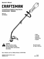
15-1ncldCurved ShafV5o5 Amp Electric
WEEDWACKER®TRIMMER
_i_lk
Before
using this product,
wARNIHG:
read this manual and follow
Save this manual
for future reference.
all its Safety Rules and Operating
instructions.
Sears, Roebuck, and Co., Hoffman Estates, IL 60179 USA
OPERATOR'SMANUAL PART NO, 18231?
PRINTED iN U,S.A,
RevoA
5/99 (51569)
Warranty Statement
2
Maintenance
11
Safety Rules
2
Service and Adjustments
12
Contents of Hardware Pack
6
Specifications
15
Assembly
6
Troubleshooting
15
Operation
8
Espa_ol
16
FULL ONE-YEAR
WARRANTY
ON CRAFTSMAN
® ELECTRIC
WEEDWACKER
® TRIMMER
For one year from the date of purchase, when this Craftsman Electric Weedwacker Trimmer is maintained according
to the operating and maintenance instructions in the operator's manual, Sears will repair, free of charge, any defect
in materials or workmanship.
This warranty excludes nylon line, bump knob, and line reels, which are expendable parts and become worn during normal
use.
If this Weedwacker Trimmer is used for commercial purposes, this warranty applies for 90 days from the date of purchase.
If this Weedwacker Trimmer is used for rental purposes, this warranty applies for 30 days from the date of purchase.
This warranty applies only while this product is in use in the United States.
WARRANTY SERVICE IS AVAILABLE BY RETURNING THE WEEDWACKER TRIMMER TO THE NEAREST SEARS SERVICE CENTER IN THE UNITED STATES.
This warranty gives you specific legal rights, and you may also have other rights which vary from state to state.
Sears, Roebuck
and Co., D/817 WA, Hoffman
Estates, IL 60179
personal injury.
_,
safety
precautions
should
be observed,
ARNING:
To guard
against
injury, basic
including the following rules for safe operation:
WARNING= Failure to obey a safety warning
can result in serious injury to yourself or to
others. Always follow the safety precautions
to reduce the risk of fire, electric shock, and
personal injury.
The purpose of safety symbols is to attract your attention to possible dangers. The safety symbols, and their
explanations, deserve your careful attention and understanding. The safety warnings do not by themselves
eliminate any danger. The instructions or warnings they
give are not substitutes for proper accident prevention
CAUTION:
Failure to obey a safety warning
may result in property damage or personal
minor or moderate injury to yourself or to others. Always follow the safety precautions to
reduce the risk of fire, electric shock, and personal injury.
,_res.
SAFETY ALERT SYMBOL= Indicates
danger, warning, or caution. May be used in
conjunction with other symbols or pictographs.
DANGER: Failure to obey a safety warning
will result in serious injury to yourself or to
others. Always follow the safety precautions
to reduce the risk of fire, electric shock, and
NOTE: Advises you of information or instructions vital to
-2-
• iMPORTANT
SAFETY iNFORMATiON
A nameplate on your unit indicates what voltage it
uses. Never connect the unit to an AC voltage that
differs from this voltage.
WARNING: When using electric gardening
tool, basic safety precautions should always
be followed to reduce the risk of fire, electric
shock, and personal injury. Carefully read and
understand the entire Operator's Manual before
using your trimmer. Pay close attention to the
Operating Instructions and Safety Warnings.
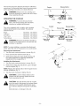
MINIMUM WiRE SiZE FOR EXTENSION CORDS FOR
120 VOLT APPLIANCES USING 0=6 AMPS
READ ALL iNSTRUCTiONS
ELECTRICAL
SAFETY
WARNINGS
Cord length (ft)
25
50
100
150
Wire size (AWG)
16
16
16
14
Inspect all extension cords and the unit power
connection periodically. Look closely for deterioration,
cuts or cracks in the insulation. Also inspect the
connections for damage. Repair or replace the cords
if any defects appear.
o This tool is double-insulated. Use only identical
replacement parts when servicing. Repair or replace
damaged cords.
• WARNING: To reduce the risk of electrical shock, use
only extension cords approved for outdoor use, such
as an extension cord of cord type SW-A, SOW-A,
STW-A, STOW-A, SJW-A, SJOW-A, SJTW-W or
SJTOW-A. A 2-wire extension cord (an extension cord
without a ground) may be used because the tool is
double insulated. However, a 3-wire extension cord
(an extension cord with a ground) that uses a NEMA
type connector (parallel blade, U ground) may also be
used. Extension cords are available from your local
retailer. Use only round-jacketed extension cords
approved for outdoor use.
Avoid dangerous environments. Never operate your
unit in damp or wet conditions. Moisture is a shock
hazard.
o Do not use the unit in the rain.
Do not handle the plug or the unit with wet hands.
BEFORE
OPERATING
Read the instructions carefully. Be familiar with the
controls and proper use of the unit.
Do not operate this unit when tired, ill, or under the
influence of alcohol, drugs, or medication.
To reduce the risk of electrical shock, this unit has a
polarized plug (one blade is wider than the other) and
will require the use of a polarized extension cord. This
unit plug will fit into a polarized extension cord only
one way. If the plug does not fit fully into the extension
cord, reverse the plug. If the plug still does not fit,
obtain a correct polarized extension cord. A polarized
extension cord will require the use of a polarized wall
outlet. This plug will fit into a polarized wall outlet only
one way. If the plug does not fit fully into the wall outlet, reverse the plug. If the plug still does not fit, contact a qualified electrician to install the proper wall outlet. Do not change the unit plug, extension cord receptacle, or extension cord plug in any way.
Children and teens under the age of 15 must not use
the unit, except for teens guided by an adult.
o All guards and safety attachments must be installed
properly before operating the unit.
Inspect the unit before use. Replace damaged parts.
Make sure all fasteners are in place and secure.
Replace parts that are cracked, chipped, or damaged
in any way. Do not operate the unit with loose or
damaged parts.
Use only 0.080 in (2.03 mm) diameter genuine
Craftsman ®replacement line. Never use
metal-reinforced line, wire, or rope, etc. These can
break off and become a dangerous projectile.
o Ground Fault Circuit Interrupter (GFCI) protection
should be provided on the circuit(s) or outlet(s) to be
used for this unit. Receptacles are available having
built-in GFCI protection and may be used for this measure of safety.
o Be aware of the risk of injury to the head, hands and
feet.
Clear the area to be cut before each use. Remove all
objects such as rocks, broken glass, nails, wire, or
string which can be thrown or become entangled in
the cutting attachment.
CORD SETS: Make sure your cord set is in good condition. When using a cord set, be sure to use a cord
that is heavy enough to carry the current that your unit
will draw. An undersized cord set will cause a drop in
line voltage resulting in loss of power and overheating.
The table shows the correct size to use depending on
the cord length and nameplate amperage rating. If in
doubt, use the next heavier size line gauge. The smaller the gauge number, the heavier the cord. To reduce
the possibility of disconnection of the unit cord from
the cord set during operation, see Fig. 9.
Clear the area of children, bystanders, and pets. At a
minimum, keep all children, bystanders and pets
outside a 50 feet (15 m.) radius; there still may be a
risk to bystanders from thrown objects. Bystanders
should be encouraged to wear eye protection. If you
are approached, stop the motor and cutting attachment immediately.
Before each use, check that the cutting head is
correctly fixed and that the trigger returns automatically to the off position.
-3-
WHILE
OPERATING
not cutting.
• Wear safety glasses or goggles that are marked as
meeting ANSI Z87.1-1989 standards, and ear/hearing
protection when operating this unit. Wear a face or
dust mask if the operation is dusty. Long sleeve shirts
are recommended.
o Wear heavy, long pants, boots and gloves. Do not
wear short pants, sandals or go barefoot.
o
Always stop the unit when cutting is delayed or when
walking from one cutting location to another.
o
If you strike
object, stop
age. Do not
operate the
or become entangled with a foreign
the unit immediately and check for damoperate before repairing damage. Do not
unit with loose or damaged parts.
Stop and switch the motor to off for maintenance,
repair, or for changing the cutting attachment or other
attachments.
o Dress Properly - Do not wear loose clothing or jewelry.
They can be caught in moving parts. Secure hair
above
shoulder level.
Use only genuine Craftsman ®replacement parts
when servicing this unit. These parts are available
from your authorized service dealer. Do not use parts,
accessories or attachments not authorized by
Craftsman for this unit. Doing so could lead to
serious injury to the user, or damage to the unit, and
void your warranty.
Stay Alert - Watch what you are doing. Use common
sense.
Adjust the assist handle to your size to provide the
best grip.
Be sure the cutting attachment is not in contact with
anything before starting the unit.
Keep unit clean of vegetation and other materials.
They may become lodged between the cutting attachment and shield.
The cutting attachment shield must always be in place
while operating the unit as a trimmer. Do not operate
unit without both trimming lines extended, and the
proper line installed. Do not extend the trimming line
beyond the length of the shield.
OTHER SAFETY
WARNINGS
o Disconnect the unit from the power supply when not in
use, before servicing, when changing accessories
such as cutting head, and the like.
Use the unit only in daylight or good artificial light.
Maintain trimmer with care. Keep the unit clean and
serviced for the best and safest performance. Follow
the maintenance instructions. Always use a clean cloth
when cleaning. Never use strong detergents, gasoline,
petroleum-based products, or any strong solvents to
clean the unit.
Avoid accidental starting. Do not carry plugged-in unit
with your finger on the switch. Be sure switch is off
when plugging in.
• Do not abuse the power cord. Never carry the unit by
the cord or yank the plug out of the receptacle. Keep
the cord away from heat, oil and sharp edges.
Keep your unit in good working condition. Follow
instructions for servicing and changing accessories.
Inspect unit periodically, and if damaged, have it
repaired by an authorized service facility. Inspect
extension cords periodically and replace if damaged.
Keep handles dry, clean, and free from oil and grease.
• Use the right tool. Only use this tool for the purpose
intended. The line head cutting attachment with this
unit is designed only for cutting grass, light weeds and
decorative trimming. Do not use the attachment as
an edger.
o Do not overreach. Always keep proper footing and
balance.
Store the unit in a locked up and dry, or high and dry
place to prevent unauthorized use or damage. Keep
out of the reach of children.
Always hold the unit with both hands when operating.
Keep a firm grip on both the front and rear handle or
grips.
Never douse or squirt the unit with water or any other
liquid. Keep handles dry, clean and free from debris.
Clean after each use, see Cleaning and Storage
instructions.
Keep hands, face, and feet at a distance from all
moving parts. Do not touch or try to stop the cutting
attachment when it is rotating.
Keep these instructions. Refer to them often and use
them to instruct other users. If you loan someone this
unit, also loan them these instructions.
Do not operate the unit faster than the speed needed
to cut or trim. Do not run the unit at high speed when
SAVE THESE INSTRUCTIONS
-4-
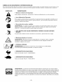
SAFETY
AND iNTERNATiONAL
SYMBOLS
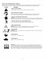
This operator's manual describes safety and international symbols and pictographs that may appear on this product.
Read the operator's manual for complete safety, assembly, operating and maintenance and repair information.
SYMBOL
MEANING
" SAFETY
ALERT
SYMBOL
Indicates danger, warning, or caution. May be used with other symbols.
= READ OPERATOR'S
MANUAL
Failure to follow operating instructions and safety precautions in operator's manual can
result in serious injury. Read operator's manual before starting or operating this unit.
= WEAR
EYE AND HEARING
PROTECTION
WARNING: Thrown objects and loud noise can cause severe eye injury and hearing loss. Wear
eye protection meeting ANSI Z87.1-1989 standards and ear protection when operating this unit.
= THROWN
OBJECTS
CAN CAUSE
SEVERE
INJURY
Do not operate unit without proper attachments and guards in place.
', KEEP CHILDREN
AWAY
WARNING: Keep all bystanders, especially children and pets, at least 50 feet (15 m.)
from the operating area. Stop unit immediately if you are approached.
= SHARP
BLADE
WARNING:
There is a sharp blade on the cutting attachment
do not touch blade.
', SPEED
shield. To prevent serious injury,
SWITCH
Indicates "HIGH" or "FASTEST" speed.
', SPEED
SWITCH
Indicates "LOW" or "SLOWEST" speed.
WARNING:
The operation of any power tool can result in foreign objects being thrown into
your eyes, which can result in severe eye damage. Before beginning power tool operation,
always wear safety goggles or safety glasses with side shields that are marked as meeting ANSI
Z87.1-1989 standards and a full face shield when needed. We recommend Wide Vision Safety
Mask for use over eyeglasses or standard safety glasses with side shields, available at Sears.
-5-
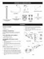
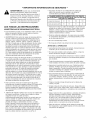
Cutting
Operator's
Attachment
Shield
Manual
Assist Handle
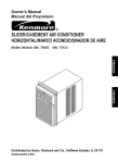
(4) Hex Jam Nuts -(1/4 x 20)
for Assist Handle
(4) Screws
(1/4-20 x 2-1/4)
- for Assist Handle
(actual size)
(4) Screws (10-24 x 1/2)
- for Cutting Attachment
Shield
Middle Handle
Clamp
(actual size)
CARTON
CONTENTS
• Hardware Pack
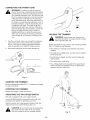
7. Tighten the clamp screws evenly, until the assist
handle is secure.
iNFORMATION
Assist Handle
To ensure safe and proper operation of your unit, all
parts and hardware you assemble must be tightened
securely.
TOOLS
REQUIRED
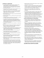
Top Handle
Clamp
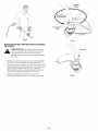
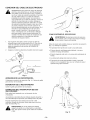
6. While holding the unit in the operating position
(Fig. 3), position the assist handle to the location
that provides you the best grip.
o Trimmer
ASSEMBLY
(actual size)
to
Screws
_--_
FOR ASSEMBLY
Middle
Clamp
Handle
Clamp
o Large Phillips Screwdriver
Regular Phillips Screwdriver
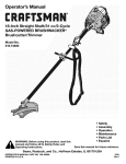
TO ASSEMBLE
HANDLE
AND ADJUST
Bottom
Handle
P
ASSIST
1.
Place the assist handle between the top and middle
clamp pieces (Fig. 1).
2.
While holding the three pieces together, install the
four (4) screws through the top clamp and into middle clamp.
Shaft Housing
• ,
Fig. 1
NOTE: The holes in the top and middle clamp will line up
only when assembled correctly.
3.
Place the clamps and assist handle the over the
shaft housing and onto the bottom clamp.
4.
Hold each hex nut in the bottom clamp recess with a
finger. Start screws with a large Phillips screwdriver.
Do not tighten until you make the handle adjustment.
5.
Slide the assist handle in or out until the arrow/white
line on the decal touches the clamp assembly
(Fig. 2).
Fig. 2
-6-
Nuts
Cutting
Attachment
Cutting
Attachment
Shield
Fig. 3
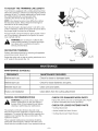
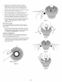
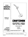
TO iNSTALL CUTTING ATTACHMENT
_
Fig. 4
SHIELD
trimmer
without
the cutting
shield
AUTION"
To avoid
injury,attachment
never operate
the
installed. If the trimmer is operated without it in
place, you will VOID the warranty.
ws
1. Place the cutting attachment shield onto the shaft housing
above the clamp assembly (Fig. 4).
2. Push the cutting attachment shield down to the top of the
cutting attachment assembly and then rotate the cutting
attachment shield 180 °. Align the 4 screw holes and fit the
cutting attachment shield securely in the recessed pocket
(Fig. 4).
3. Install the four (4) screws (10-24 x 1/2) with a regular Phillips
screwdriver (Fig. 5). Tighten securely.
Fig. 5
-7-
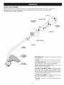
KNOW YOUR
TRIMMER
READ THIS OPERATOR'S MANUAL AND SAFETY RULES BEFORE OPERATING YOUR UNIT. Compare the
illustrations with your unit to familiarize yourself with the location of various controls and adjustments.
Save this manual for future reference.
Air Vents
HOUSING GRiP
\
TWO SPEED
SWITCH
RECESSED
PLUG
TRIGGER
\
ASSIST HANDLE
COUPLER
SHAFT
HOUSING
CUTTING
RECESSED PLUG = is where you connect the extension
cord to the unit.
SHIELD
TRIGGER = used for starting and stopping the trimmer.
TWO SPEED SWITCH - used to switch between high
and low speeds for different cutting applications.
CUTTING
ATTAC HM ENT
ASSIST HANDLE AND HOUSING GRIP = used to hold
the line trimmer during operation.
CUTTING ATTACHMENT SHIELD = protects operator
from thrown debris. Contains line cut-off blade to make
sure the line is not extended beyond its proper length.
Cutting attachment shield must be installed at all times
when using the cutting attachment.
CUTTING ATTACHMENT - consists of a reel housing,
reel, spring, Bump Knob, and cutting line
COUPLER = allows you to install optional attachments
on this unit.
-8-
This trimmer has been designed and built to withstand
normal use. It will provide many hours of service provided the operating instructions are closely followed.
_,
Release Button
and
body protection
reduce
risk offoot
injury
ARNING:
Always to
wear
eye, the
hearing,
when operating this unit.
OPERATING
_,
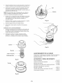
Coupler
Guide
Recess
THE COUPLER
injury,
shut offToand
unplug
the unit
before
ARNING:
avoid
serious
personal
removing or installing attachments.
Fig. 6
Coupler
Release Button
This unit is equipped with a coupler, which enables
optional attachments to be installed. The optional
attachments are:
Edger ......................
Cultivator ...................
Tree Pruner .................
Model No. 316.790401
Model No. 316.790410
Model No. 316.790430
Turbo Blower ................
Model No. 316.790420
\'- ,
P.mary
H°le
i f
Upper Shaft
Housing
WARNING:
Read and understand operator's
manual for the attachment to be used with this
unit prior to operation.
_
Lower Shaft
Housing
Fig. 7
NOTE: To make installing or removing the attachment
easier, place the unit on the ground or on a work bench.
Removing the Attachment:
1. Turn the knob counterclockwise
to loosen (Fig. 6).
2.
Press and hold the release button (Fig. 6).
3.
While firmly holding the upper shaft housing, pull
the cutting attachment or optional attachment
straight out of the coupler (Fig. 7).
L
installing the Attachment:
1. Turn the knob counterclockwise
2.
to loosen (Fig. 6).
While firmly holding the attachment, push it straight
into the coupler (Fig. 7).
Fig. 8
NOTE: Aligning the release button with the guide recess
will help installation (Fig. 7).
3. Turn the knob clockwise to tighten (Fig. 8).
primary
hole Lock
and securely
tighten
the in
knob
CAUTION:
the release
button
the
before operating this unit.
CAUTION: The attachments with the coupler
are to be used in the primary hole unless stated
otherwise in the specific attachments operator's manual. Using the wrong hole could lead
to
personal injury, or damage to the unit.
-9-
Knob
CONNECTING
THE POWER
CORD
WARNING: To reduce the risk of electrical
shock, this unit has a polarized plug (one blade
is wider than the other) and will require the use
of a polarized extension cord. This unit plug will
fit into a polarized extension cord only one way.
If the plug does not fit fully into the extension
cord, reverse the plug. If the plug still does not
fit, obtain a correct polarized extension cord. A
polarized extension cord will require the use of
a polarized wall outlet. This plug will fit into a
polarized wall outlet only one way. If the plug
does not fit fully into the wall outlet, reverse the
plug. If the plug still does not fit, contact a
qualified electrician to install the proper wall
outlet. Do not change the unit plug, extension
cord receptacle, or extension cord plug in any
way.
1.
2.
HI
Fig. 10
HOLDING
THE TRIMMER
WARNING: Always wear eye, hearing, foot
and body protection to reduce the risk of injury
when operating this unit.
Use the cord hook when you connect the extension
cord to the power cord to prevent disconnection
(Fig. 9). Use only an outdoor-approved extension
cord as specified in the SAFETY RULES section.
Before operating the unit, stand in the operating position
(Fig. 11). Check for the following:
Secure the extension cord to motor housing as
• The operator is wearing eye protection
clothing.
and proper
The right arm is slightly bent, and the hand is holding
the housing grip.
The left arm is straight, and the hand is holding the
assist handle.
o The unit is below waist level.
The cutting attachment is parallel to the ground and
easily contacts the vegetation to be cut without the
operator having to bend over.
Fig. 9
STARTING
THE TRIMMER
Be in the operating position (Fig. 11). Squeeze the trigger
to start the trimmer.
STOPPING
THE TRIMMER
Release the trigger to stop the trimmer.
OPERATING
THE TWO=SPEED
This unit is equipped with a two-speed
SWITCH
switch;
a powerful high speed for demanding yard work, and
a precision low speed for light-duty yard work.
Push the switch up for high speed trimming. Push the
switch down for low speed trimming (Fig. 10).
CAUTION: Do not use the unit for demanding
yard work with the switch in the low speed.
This may cause the unit to overheat and fail.
Fig. 11
-t0-
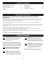
TO ADJUST
THE TRiMMiNG
LiNE LENGTH
Your trimmer is equipped with a cutting attachment that
allows the operator to release more trimming line without
stopping the unit. To release additional line, lightly bump
the cutting attachment on the ground while
operating the trimmer at high speed (Fig. 12).
NOTE: Line release becomes more difficult as cutting
line becomes shorter. Always keep the trimming line
extended to its full cutting length.
Each time the head is bumped, about 1 inch (25.4 mm)
of line is released. A blade in the guard will cut the line to
the proper length if excess line is released.
Fig. 12
For best results, bump the head on bare ground or hard
soil. If line release is attempted in tall grass, the motor
may overheat and fail.
WARNING:
Do not remove or alter the line
cutting blade assembly. Excessive line length
can cause unit to overheat and result in
serious personal injury.
DECORATIVE
TRIMMING
Perform decorative trimming by removing all vegetation
around trees, posts, fences, etc.
Rotate the entire unit so that the cutting attachment
a 30 ° angle to the ground (Fig. 13).
MAINTENANCE
is at
Fig. 13
SCHEDULE
FREQUENCY
MAINTENANCE
REQUIRED
Before each use
Check for loose or damaged
Before each use
Check for loose fasteners
Between
Clean units and labels.
each use
Every Line Installation
GENERAL
and parts.
Clear debris from the cutting
RECOMMENDATIONS
CHECK
parts.
attachment
FOR DAMAGED/WORN
PARTS
Inspect the unit for any worn or damaged parts. Repair
or replace damaged parts before operating.
WARNING: To prevent serious injury, never
perform maintenance on the unit while it is
running. Shut off and unplug the unit before
cleaning or performing any maintenance.
CHECK
FOR LOOSE FASTENER
o Cutting Attachment
The warranty on this line trimmer does not cover
items that have been subjected to operator abuse or
negligence. To receive full value from the warranty, the
operator must maintain the unit as instructed in this
operator's manual.
• Assist Handle Hex Nuts/Screws
Cutting Attachment Shield Screws
These required maintenance procedures should be
performed at the frequency stated in the table. They
should also be included as part of any seasonal tune-up.
-tl
-
PARTS
CLEAN
UNIT AND LABELS
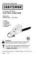
Winding the existing reel with new line
NOTE: Before installing new trimming
existing reel, remove any old line from
Head by pulling the line out of the line
holes (See Figs. 15 and 16 for location
WARNING:
To prevent injury, shut off and
unplug the unit before cleaning or performing
any maintenance.
1.
Do not use any strong detergents on the plastic housing
or the handle. They can be damaged by certain
household cleaners that contain aromatic oils such as
pine and lemon, and by solvents such as kerosene.
Wipe off any moisture with a soft cloth.
line onto the
the RapidRewind
loading or locking
of holes).
Line up the arrow on the reel with the arrow on the
reel housing (Fig. 14).
NOTE: Do not wind the reel before the second line is
installed into the reel.
• Clean the unit and labels using a damp cloth with a
mild detergent.
when
installing
trimming
the unit.
If
ARNING:
Always
use line
the on
correct
line length
longer line is used than specified in this manual, the line may not release properly.
_,
Wipe off the unit with a clean dry cloth.
o Keep air vents free from debris at all times.
2_
SERVICING
OF DOUBLE
INSULATED
UNITS
This unit is double-insulated. In a double-insulated
unit, two systems of insulation are provided instead of
grounding. No grounding means is provided on a
double-insulated unit, nor should a means for grounding
be added to this unit.
Insert 10 feet (3 m) of trimming line into one of the
two eyelets and push it up through the line loading
hole in the reel (Fig. 15). Do not bend the line when
inserting it into the eyelet.
TOP VIEW OF THE RAPIDREWIND
HEAD
Reel
Housing
Servicing a double-insulated unit requires extreme care
and knowledge of the system, and should be done only
by qualified service personnel. Replacement parts for a
double-insulated unit must be identical to the parts they
replace. Refer any repair to an authorized service dealer.
A double-insulated unit is marked with the words
"DOUBLE INSULATION" or "DOUBLE INSULATED."
LINE INSTALLATION
FOR THE
RAPIDREWIND
TM HEAD
Bump
Knob
Reel
The trimming line in the RapidRewind Head may be
replaced by two different methods.
Winding the existing reel with new line
Fig. 14
Installing a prewound reel
TO INSTALL NEW TRIMMING LINE, IT IS NOT
NECESSARY TO REMOVE THE BUMP KNOB.
The correct
Trimming
Line
line to use
WARNING:
Always use Craftsman® trimmer
replacement line. To avoid injury, never use
metal-reinforced line, wire, or rope, etc..
These can break off and become a dangerous
projectile.
It is very important to use the correct size line. Use line
with a diameter of 0.080 inch (2.03 mm). The unit may
overheat and fail if you use a size other than specified.
Eyelet
Line Loading Hole
Fig. 15
-t2-
3.
Insert the line into the locking hole no more than
1/2 inch (12.7 mm) (Fig. 16). Do not push the line too
far into the inner reel. A small loop is formed when
the line is inserted correctly.
4.
Pull the line away from the head until the line is tight
against the reel (Fig. 17).
5.
Repeat the procedure with the second eyelet and
use the same amount of line as specified in Step 2.
6.
Wind the inner reel counterclockwise until approximately four (4) inches of line remains outside of the
eyelets in the reel housing (Fig. 18).
7.
If winding the line becomes difficult or the line jams,
pull the ends of the line away from the head and
continue winding the reel counterclockwise (Fig. 19).
Fig. 17
Releasing the reel
If the RapidRewind Head does not operate correctly
when bumping the head on the ground, use the following instructions.
1.
Pull the ends of the line firmly away from the head
to release the reel (Fig. 19). If this procedure
does not release the reel, follow the "Cleaning the
RapidRewind" instructions below.
f
Cleaning the RapidRewind
If the RapidRewind Head becomes difficult to wind or
does not operate correctly when bumping the head on
the ground, use the following instructions.
1.
Fig. 18
If you need to remove the Bump Knob to clean
the head or remove jammed, excess line, hold
the reel housing, and unscrew the Bump Knob
counterclockwise (Fig. 20).
Fig. 19
Locking Hole
Fig. 16
Fig. 20
-t3-
Remove the Bump Knob, foam seal, spring, reel,
and trimming line from the reel housing (Fig. 21).
2.
3.
Remove any debris or grass from the knob, spring,
reel, and foam seal. Remove any existing line from
the reel before cleaning. Wash the reel with warm
soapy water (Fig. 22).
NOTE: The reel must be completely dry before
reinstalling it into the reel housing. Do not lubricate the
reel or reel housing assembly.
.
5.
Clean the shaft and the inner surface of the reel
housing. To clean the shaft underneath the plunger,
press down on the plunger (Fig. 23). Remove any dirt
and/or debris from the shaft.
Fig. 23
Install the reel, spring, foam seal, and Bump Knob
into the reel housing (Fig. 21).
6. Tighten the Bump Knob clockwise.
7.
Install new line as described on pages 12 and 13.
Installing a Prewound Reel
1.
Insert the ends of the two trimming lines into the
eyelets in the reel housing (Fig. 24), then grasp the
ends and pull firmly to release the line from the
holding slots in the reel.
2.
Hold the reel in place and install the Bump Knob,
spring and foam seal in the counterclockwise
direction. Line installation is now complete.
Reel
_,_
Fig. 24
Spring
_-
STORING
Foam Seal
Bump Knob
THE UNIT
Clean the unit thoroughly before storing it. Store the unit
in a dry, well-ventilated area, locked-up or up high, out
of the reach of children.
_=_
ACCESSORIES/REPLACEMENT
Fig. 21
Replacement Line
.......................
Replacement Line Cartridge
-t4-
..............
181472
71-85825
Reel Spring .............................
610317
Bump Head Knob Assembly ................
Cutting Attachment Shield and Blade Assembly
153066
.153646
Cutting Attachment
180531
Shoulder Strap
Fig. 22
PARTS
Shield Screws ...........
..........................
682075
TROUBLE
CAUSE
REMEDY
Unit Will Not Start or
Unit Stops
Unit unplugged
Cutting Attachment Will Not Turn
When Trigger is Squeezed
Cutting attachment
debris
Cutting Attachment
Advance Line D
Cutting Attachment out of line
Refill cutting line
Reel bound up
Replace reel
Cutting attachment dirty
Clean cutting head reel and reel
housing
Indexing teeth worn or burred
Replace reel and reel housing
Line welded
Disassemble, remove the welded
section, and rewind the line
Line twisted when refilled
Disassemble cutting attachment
and rewind the reel
Not enough line exposed
Push the Bump Knob and pull
out the line until a minimum of
4 inches (102mm ) is outside of
cutting attachment
Oil in cutting attachment
Clean cutting attachment
Will Not
Cutting Line Advances
Uncontrollably
Check cord to see if it is plugged
into an electrical outlet
bound with grass or
Stop unit and clean cutting
attachment
MOTOR
Motor Type ......................................................................
110 Vok Electdc
Operating RPM (both lines fully extended)
Low Speed
.................................................................
5,000-5,500
High Speed .................................................................
Amperage
...........................................................................
6,000-7,000 rpm
5.5 Amps
Ignition Switch
DRIVE
...........................................................
SHAFT
AND
Drive Shaft Housing
Shoulder Strap
CUTTING
Momentary
............................................................
Steel Tube, Coupler
Optional
.............................................................
Line Spool Diameter
Trigger Switch
ATTACHMENT
.........................................................................
Cutting Mechanism
rpm
RapidRewind
Head
...............................................................
4 in. (102 mm)
Trimming Line Diameter .........................................................
Cutting Path Diameter .............................................................
0.080 in. (2.03 mm)
15 in. (381 mm)
Operating
Weight
.........................................................
Approx.
-15-
10.0 Ibs. (4.54 kg)
Declaraci6n de Garantia Limitada
16
Mantenimiento
25
Normas de Seguridad
Contenidos de la Bolsa de Piezas
16
Servicio y Ajustes
26
Ensamble
20
20
Especificaciones
Resoluci6n de Problemas
29
29
Operaci6n
22
GARANTIA TOTAL DE UN Ai_O PARA LA RECORTADORA
WEEDWACKER
®
ELECTRICA
CRAFTSMAN
®
Sears reparara sin costo alguno todo defecto de material o de mane de obra durante un periodo de un abe a partir de la fecha de
compra, siempre que esta recortadora electrica Craftsman Weedwacker haya sido mantenida de acuerdo con las instrucciones de
operaci6n y mantenimiento contenidas en el manual del operador.
Esta garantia no incluye la Ifnea de nil6n, la perilla percusiva y los carretes de linea, ya que estas piezas son desgastables y se
deterioran durante el uso normal.
Si esta recortadora Weedwacker se utiliza con fines comerciales, esta garantfa tendra una vigencia de 90 dfas a partir de la fecha de
compra. Siesta recortadora Weedwacker se utiliza con fines de alquiler, esta garantia tendra una vigencia de 30 dias a partir de la
fecha de compra.
Esta garantia tendra validez s61o mientras esta unidad sea utilizada en los Estados Unidos.
EL SERVICIO A TRAVES DE LA GARANTIA ESTARA DISPONIBLE CUANDO LLEVE LA RECORTADORA WEEDWACKER AL
CENTRO DE SERVICIO SEARS MAS CERCANO EN LOS ESTADOS UNIDOS.
Esta garantia le otorga derechos legales especificos,
estado.
Sears, Roebuck and Co., D/817 WA, Hoffman
,_
yes posible que usted tambien tenga otros derechos que varian de acuerdo al
Estates,
IL 60179
cumplir
con las precauciones
seguridad,
ADVERTENClA:
Para prevenir basicas
lesiones,dedebe
incluyendo las siguientes normas para una
operaci6n segura:
,_
Los simbolos de seguridad se utilizan para Ilamar su atenci6n
sobre posibles peligros. Los simbolos de seguridad y sus
explicaciones merecen su atenci6n y comprensi6n detalladas.
Los simbolos de seguridad por si mismos no eliminan ningun
peligro. Las instrucciones o advertencias que ofrecen no substituyen las medidas adecuadas de prevenci6n de accidentes.
_,
ADVERTENClA: El no seguir una advertencia de
seguridad puede conducir a que usted u otras
personas sufran lesiones graves. Siga siempre las
precauciones de seguridad para reducir el riesgo de
incendio, sacudidas electricas y lesiones personales.
PRECAUClON: El no seguir una advertencia de
seguridad puede conducir a dahos materiales o a
que usted u otras personas sufran lesiones menores
o moderadas. Siga siempre las precauciones de
seguridad para reducir el riesgo de incendio,
sacudidas electricas y lesiones personales.
peligro,
advertencia
o precauci6n.
Puede set
IMBOLO
DE ALERTA
DE SEGURIDAD:
Indica
utilizado junto con otros sfmbolos o figuras.
NOTA: Le ofrece informaci6n o instrucciones que son
esenciales para la operaci6n o mantenimiento del equipo.
PELIGRO: El no obedecer una advertencia de
seguridad puede conducir a que usted u otras
personas sufran lesiones graves. Siga siempre las
precauciones de seguridad para reducir el riesgo de
incendio, sacudidas electricas y lesiones personales.
-t6-
e IMPORTANTE
ADVERTENCIA:
INFORMACION
Cuando use una herramienta
CALIBRE MINIMO DEL ALAMBRE PARA LOS CABLES
DE EXTENSION PARA ARTEFACTOS DE t20 VOLTIOS QUE
UTILIZAN 0-6 AMPERIOS
LEA TODAS LAS INSTRUCCIONES
DE SEGURIDAD
=
• Una placa de dates en su unidad indica el voltaje que
utiliza. No conecte nunca la unidad a un voltaje de
corriente alterna que difiera de este voltaje.
electrica para jardineria, debe tomar siempre
precauciones de seguridad basicas para evitar el
riesgo de incendio, descarga electrica, y lesiones
personales. Lea en detalle y comprenda todo el
Manual del Operador antes de utilizar su recortadora. Preste mucha atenci6n alas Instrucciones de
Operaci6n y alas Advertencias de Seguridad.
ADVERTENCIAS
DE SEGURIDAD
Longitud del cable (pies)
25
50
100
150
Calibre del alambre
16
16
16
14
(AWG)
Inspeccione todos los cables de extensi6n y la conexi6n de
energia de su unidad con frecuencia. Observe bien si existe
deterioro, cortes o grietas en el aislamiento. Inspeccione
tambien si existen dahos en las conexiones. Cambie los
cables si existen defectos o dafios.
ELECTRICA
Esta herramienta cuenta con un aislamiento doble. Use s61o
piezas de repuesto identicas cuando realice el servicio.
Repare o cambie los cables dafiados.
Evite los ambientes peligrosos. No opere nunca su unidad
en condiciones de humedad. La humedad presenta un tiesgo de descarga electrica.
ADVERTENCIA: Para reducir el riesgo de descarga electrica,
use s61o cables de prolongaci6n aprobados para use en
exteriores, como cables de extensi6n o cables tipo SW-A,
SOW-A, STW-A, STOW-A, SJW-A, SJOW-A, SJTW-W or
SJTOW-A. Puede usar un cable de extensi6n de dos cables
(un cable de extensi6n sin conexi6n a tierra) porque esta
herramienta cuenta con aislamiento doble. Sin embargo,
tambien puede usar un cable de extensi6n de tres cables (un
cable de extensi6n con conexi6n a tierra) que use un conector NEMA (ficha de cuchillas paralelas, conexi6n a tierra en
U). Puede adquirir cables de prolongaci6n en su distribuidor
local. Use solamente cables de prolongaci6n de camisa
cilfndrica aprobados para usar en exteriores.
o
No use la unidad bajo la Iluvia.
o
No toque el enchufe ni la unidad con las manos mojadas.
ANTES DE LA OPERACION
Lea todas las instrucciones con cuidado. Conozca bien los
controles y el uso correcto de la unidad.
No opere esta unidad si esta cansado, enfermo, o bajo los
efectos del alcohol, drogas o medicamentos.
Los nifios y los adolescentes menores de 15 a_os no deben
operar las unidades, excepto pot los adolescentes guiados
per un adulto.
Para reducir el riesgo de descarga electrica, la unidad tiene
un enchufe polarizado (una patilla es mas ancha que la otra)
y requiere el uso de un cable de extensi6n polarizado. El
enchufe de esta unidad calzara en un cable de extensi6n
polarizado s61o en una direcci6n. Si el enchufe no calza
completamente en el cable de extensi6n, invierta el enchufe.
Si el enchufe aQn no calza, obtenga un cable de extensi6n
polarizado adecuado. Un cable de extensi6n polarizado
requiere el use de un toma de pared polarizado. Este
enchufe calzara en un toma de pared polarizado s61o en una
direcci6n. Si el enchufe con calza completamente en el toma
de la pared, invierta el enchufe. Si el enchufe aun no calza,
comuniquese con un electricista calificado para que instale
un toma de pared adecuado. No cambie el enchufe de la
unidad, el receptaculo del cable de extensi6n ni el enchufe
del cable de extensi6n de ningOn mode.
Todas las protecciones y accesorios de seguridad deben
estar instalados en forma correcta antes de operar la unidad.
Inspeccione la unidad antes de su uso. Cambie las partes
dahadas. Verifique que todos los sujetadores esten en su
lugar y asegurados. Cambie las partes que esten quebradas,
cascadas o dahadas de cualquier modo. No opere esta
unidad con partes flojas ni dafiadas.
Use Qnicamente Ifnea de repuesto genuina Craftsman® de
0.080 pulgadas (2.03 mm) de diametro. No use nunca Ifnea
con refuerzo metalico, alambre, cuerdas, etc. las cuales
pueden desprenderse y convertirse en peligrosos proyectiles.
Debe proveerse protecci6n de interrupci6n de circuito
accionada per corriente de perdida a tierra (GFCI) para el/los
circuito(s) o toma(s) que se utilizaran para esta unidad.
Existen receptaculos disponibles que tienen protecci6n
GFCI incorporada y pueden set utilizados para esta medida
de seguridad.
JUEGOS DE CABLES: Verifique que su juego de cables este
en buenas condiciones. Cuando use un juego de cables,
asegurese de usar un cable que sea Io
suficientemente pesado para conducir la corriente que consuma su unidad. Un cable de menor tamafio causara una
cafda de voltaje en la linea Io que conducirb_ a una
perdida de energfa y calentamiento excesivo. La tabla
indica el tamafio correcto que debe usar de acuerdo a la
Iongitud del cable y al valor de amperios en la placa de
dates. Si tiene dudas, utilice el tamaho siguiente mayor de
line& Cuanto menor sea el calibre, mas pesado es el cable.
Para reducir la posibilidad de desconexi6n de la unidad del
juego de cables durante la operaci6n, vea la Fig. 9.
o
Tenga en cuenta el riesgo de lesiones en la cabeza, las
manos y los pies.
o
Limpie el Area de corte antes de cada uso. Saque todos los
objetos como rocas, vidrios rotos, clavos, alambre o cuerda
que puedan salir despedidos o enredarse en el accesorio de
corte.
Aleje a todos los nifios, espectadores y animales domesticos
del area. Mantenga a todos los ni_os, espectadores y
animales domesticos per Io menos fuera de un radio de
50 pies (15 m.); aQn puede existir un riesgo de objetos
arrojados hacia los espectadores. Debe sugerir a los
espectadores que usen protecci6n ocular. Si se le acercan,
pare el motor y el accesorio de corte de inmediato.
Antes de cada uso, verifique que la cabeza de corte este
bien asegurada y que el gatillo regresa en forma automatica
a la posici6n de apagado.
-t7-
DURANTELAOPERACION
Apague siempre el motor cuando demote el corte o mientras
camina entre zonas de corte.
• Use lentes o gafas de protecci6n que cumplan con las
normas ANSI Z87.1-1989, y protecci6n para sus
oidos/audici6n mientras opere esta unidad. Use siempre
una mascara facial o para protegerse contra el polvo si la
operaci6n levanta polvo.
Si golpea o se enreda con algun objeto extrato, apague el
motor de inmediato y verifique si hay datos. Repare todos
los datos antes de volver a intentar operar la unidad. No
opere la unidad si tiene piezas flojas o datadas.
Use pantalones largos y gruesos, botas y guantes. No use
pantalones cortes, sandalias ni ande descalzo.
Apague el motor para realizar todo el mantenimiento,
reparaciones o cambio del accesorio de corte u otros
accesorios.
Vista en forma adecuada - No use ropa holgada ni alhajas.
Estas pueden atascarse en las partes m6viles. Recoja su
cabello sobre el nivel de los hombros.
Use solamente repuestos legitimos cuando realice el servicio de esta unidad. Estas piezas estan disponibles en su
distribuidor autorizado. No use piezas, accesorios ni
auxiliares que no hayan sido disetados para esta unidad. Su
use puede conducir a que el usuario sufra graves lesiones o
al dane de la unidad y a la invalidaci6n de su garantfa.
Mantengase alerta - Preste atenci6n a Io que esta haciendo.
Use su sentido com0n.
Ajuste la manija auxiliar a su medida de modo que le brinde
el mejor agarre.
Mantenga la unidad libre de vegetaci6n y otros materiales.
Pueden alojarse entre el accesorio de corte y la protecci6n.
Asegurese de que el accesorio de corte no esta en contacto
con ningQn objeto antes de arrancar la unidad.
OTRAS ADVERTENClAS
La protecci6n accesoria de corte debe estar siempre
colocada en su lugar mientras opere la unidad. No opere la
unidad con las dos lineas de corte extendidas, y la linea
correcta instalada. No extienda la linea de corte mas all_, de
la Iongitud de la protecci6n.
DE SEGURIDAD
Cuando la unidad no este en use, desconectela de la
fuente de energia, y tambien antes de realizar el servicio y
de cambiar accesorios tales como la cabeza de corte
y similares.
Realice un mantenimiento cuidadoso de la recortadora.
Mantenga la unidad limpia y bajo servicio a fin de obtener
el mejor resultado con la mayor seguridad. Siga las
instrucciones de mantenimiento. Use siempre un patio
limpio para limpiar la unidad. No use nunca detergentes
fuertes, gasolina, productos derivados del petr61eo ni ningOn
solvente para limpiar la unidad.
Use la unidad Onicamente con la luz del dfa o con buena luz
artificial.
*oEvite el arranque accidental. No transporte la unidad enchufada con su dedo en el interruptor. Antes de arrancarla,
verifique que elinterruptor este apagado.
No maltrate el cable de alimentaci6n. No transporte nunca la
unidad sosteniendola del cable ni tire del enchufe para
sacarlo de la toma. Mantenga el cable lejos del calor, del
aceite y de los bordes cortantes.
No se estire demasiado. Mantenga siempre una posici6n y
equilibrio adecuados.
Mantenga su unidad en buenas condiciones de
funcionamiento. Siga las instrucciones para realizar el
servicio y para cambiar los accesorios. Inspeccione la
unidad con frecuencia, y siesta datada, hagala reparar en
un centro de servicio autorizado. Inspeccione con frecuencia
los cables de extensi6n y cb,mbielos si estan datados.
Mantenga las manijas secas, limpias y libres de aceite y
grasa.
Sostenga siempre la unidad con ambas manos mientras
este en funcionamiento. Sostenga con firmeza tanto el
mango come la manija auxiliar.
Guarde la unidad bajo Ilave en un lugar adecuado y seco
para evitar que sea usada pot personas no autorizadas y se
date, fuera del alcance de los nihos.
Mantenga las manes, la cara y los pies lejos de todas las
partes m6viles. No intente tocar ni detener el accesorio de
corte mientras gira.
Nunca moje ni rocfe la unidad con agua ni con ningun otro
liquido. Mantenga las manijas secas, limpias y sin residuos.
Limpie la unidad luego de cada uso, lea las instrucciones de
Limpieza y AImacenamiento.
Use la herramienta adecuada. No use esta unidad para
ninguna tarea para la cual no ha sido disehada.
Use la herramienta adecuada. No utilice esta herramienta
para ninguna tarea excepto aquella para la que fue disefiada. El accesorio de cabeza de corte de linea de esta unidad
esta disehado s61o para cortar cesped, hierbas delgadas y
para realizar recorte decorativo. No use el accesorio como
un recortador de bordes.
Guarde estas instrucciones. Consultelas con frecuencia y
utilicelas para ensefiar a otros usuarios. Si le presta esta
unidad a alguien, prestele tambien estas instrucciones.
GUARDE
-t8-
ESTAS INSTRUCClONES
SIMBOLOS
DE SEGURIDAD
E INTERNACIONALES
Este manual del operador describe los simbolos y figuras de seguridad e internacionales que pueden aparecer en este producto. Lea el
manual del operador para obtener informaci6n correcta acerca de la seguridad, ensamble, operaci6n y mantenimiento y reparaci6n.
SIMBOLOS
SIGNIFICADOS
= Sirnbolo
de Alerta
de Seguridad
Indica peligro, advertencia, o precauci6n.
= Lea el Manual
Puede ser utilizado junto con otros simbolos.
del Operador
El no seguir las instrucciones de operaci6n y las precauciones de seguridad contenidas en el
manual del operador puede conducir a graves lesiones. Lea el manual del operador antes de
arrancar u operar esta unidad.
= Use protecci6n
ocular y auditiva
ADVERTENCIA: Los objetos arrojados por la unidad y el ruido fuerte pueden causar graves
lesiones oculares y p6rdida auditiva. Utilice protecci6n ocular que cumpla con las normas
ANSI Z87.1 y protecci6n auditiva cuando opere esta unidad.
= LOS OBJETOS
GRAVES
QUE SALEN
DESPEDIDOS
No opere esta unidad sin tener colocados
A
= Mantenga
alejados
PUEDEN
CAUSAR
LESIONES
los accesorios y protecciones en su lugar.
a los ni_os
ADVERTENCIA: Mantenga a todos los espectadores, en especial a niSos y animales
dom_sticos a por Io menos 50 pies (15 m) del Area de corte. Apague la unidad de
inmediato si alguien se le acerca.
= CUCHILLA
AFILADA
ADVERTENCIA:
El protector accesorio de corte contiene una cuchilla afilada.
Para evitar graves lesiones personales, no toque la cuchilla.
= INTERRUPTOR
DE VELOCIDAD
Indica la velocidad "ALTA" o "MAS RAPIDA".
= INTERRUPTOR
DE VELOCIDAD
Indica la velocidad "BAJA" o "MAS LENTA".
ADVERTENCIA: La operaci6n de toda herramienta el_ctrica puede hacer que ciertos objetos
extra_os sean arrojados a sus ojos, Io que puede conducir a graves lesiones oculares. Antes de
comenzar la operaci6n de una herramienta motriz, use siempre gafas o lentes de seguridad que
indiquen que cumplen con las normas ANSI-Z87.1 de 1989, y una mascara facial completa
cuando sea necesario. Le recomendamos que utilice Wide Vision Safety Mask sobre los lentes
regulares o lentes comunes de seguridad con protecciones laterales, disponibles en las tiendas
Sears.
-t9-
Protector accesorio
Manual del operador
de corte
Manija auxiliar
(4)Torniiies(1/4-20
x 2-1/4)
- para la manija auxiliar
(tamat_oreal)
CONTENIDO
(4) Tuercas hexagonales de
presi6n -(1/4 x 20) para la
manija auxiliar
(tamat_oreal)
Abrazadera
media de la
manija
DE LA CAJA
6.
Mientras sostiene la unidad en posici6n de operaci6n
(Fig. 3), coloque la manija auxiliar en el lugar que le brinde
el mejor agarre.
7.
Ajuste los tornillos de la abrazadera en forma pareja hasta
que la manija auxiliar este firme.
= Recortadora
• Bolsa de piezas
INFORMACION
ACERCA
DEL ENSAMBLE
Manija auxiliar
Para asegurar una operaci6n segura y correcta de su
unidad, todas las partes y piezas que ensamble deben
estar ajustadas con firmeza.
HERRAMJENTAS
NECESARIAS
• Destornillador
Phillips regular
Destornillador
Phillips grande
Abrazadera
superior de la
manija
(4) Tornillos (10-24 x 1/2)
- para el protector
accesorio de corte
(tamado real)
PARA
,,
Tornilles
Abrazadera
superior de
la manija
EL ENSAMBLE
Abrazadera
media de la
manija
Abrazadera
inferior de la
manija
ENSAMBLE Y AJUSTE DE LA IVlANJJAAUXIMAR
1.
2.
Coloque la manija auxiliar entre la abrazadera superior y la
abrazadera media (Fig. 1).
Bastidor
del eje
Mientras sostiene las tres piezas juntas, instale los cuatro
(4) tornillos a traves de la abrazadera superior yen la
abrazadera media.
Tuercas
&
Fig. 1
NOTA: Los orificios de la abrazadera superior y la abrazadera
media estaran alineados s61o cuando se ensamble en forma
correcta.
3.
Coloque las abrazaderas y la manija auxiliar sobre el
bastidor del eje y encima de la abrazadera inferior.
4.
Sostenga cada tuerca hexagonal en la ranura de la
abrazadera inferior con un dedo. Comience los tornillos
con un destornillador Phillips grande. No los ajuste hasta
haber ajustado la manija.
5.
Deslice la manija auxiliar hacia adentro o hacia afuera
hasta que la flecha/linea blanca de la calcomania toque el
ensamble de la abrazadera (Fig. 2).
Fig. 2
- 20 -
del eje
Bastidor
Accesorio de
corte
Protector
accesorio
de corte
Fig. 3
INSTALACION
DE CORTE
DEL PROTECTOR
Fig. 4
ACCESORIO
nunca
la recortadora Para
sin el
protector
accesorio
de
PRECAUCION:
evitar
lesiones,
no opere
corte instalado. Si opera la recortadora sin el
protector colocado en su lugar, su garantia quedara
ANULADA.
1.
Coloque el protector accesorio de corte encima del bastidor del eje sobre el ensamble de la abrazadera (Fig. 4).
2.
Empuje el protector accesorio de corte hacia abajo hasta la
parte superior del ensamble del accesorio de corte y luego
gire el protector accesorio de corte 180 °. Alinee los 4
orificios de los tornillos y acomode el protector accesorio
de corte con firmeza en la cavidad c6ncava (Fig. 4).
3.
Instale los cuatro (4) tornillos (10-24 x 1/2) con un
destornillador Phillips regular (Fig. 5). Ajuste con firmeza.
ornillos
Fig. 5
-21 -
CONOZCA
SU RECORTADORA
LEA ESTE MANUAL DEL OPERADOR Y LAS NORMAS DE SEGURIDAD ANTES DE OPERAR SU UNIDAD. Compare las
ilustraciones con su unidad para familiarizarse con la ubicaci6n de los diferentes controles y ajustes.
Guarde este manual para su referencia futura.
RESPIRADEROS
MANGO DEL BASTIDOR
DOS
VELOCIDADES
INTERRUPTOR
DE
"_.
0
ENCNUFE
EMPOTRADO
GATILLO
\
MANIJA AUXILIAR
ACOPLADOR
BASTIDOR
DEL EJE
ENCNUFE EMPOTRADO
de extensi6n a la unidad.
PROTECTOR
ACCESORIO DE
CORTE
= es donde usted conecta el cable
GATILLO = se utiliza para arrancar y apagar la recortadora.
INTERRUPTOR DE DOS VELOCIDADES - se utiliza para
alternar entre las velocidades alta y baja para diferentes
aplicaciones del corte.
MANIJA AUXILIARY MANGO DEL BASTIDOR - se utilizan
para sostener la recortadora de linea durante la operaci6n.
ACCESORIO
DE CORTE
PROTECTOR ACCESORIO DE CORTE - protege al operador
de los escombros que salen arrojados. Contiene una cuchilla
de corte de Ifnea para asegurar que la I[nea no este extendida
mas alia de su Iongitud adecuada. El protector accesorio de
corte debe estar instalado en todo momento mientras use el
accesorio de corte.
ACCESORIO DE CORTE = consiste en un bastidor para el
carrete, el carrete, el resorte, la perilla percusiva y la linea de
corte.
ACOPLADOR
unidad.
- 22 -
= le permite instalar accesorios optativos en esta
Esta recortadora ha sido dise_ada y construida a modo de
tolerar un uso normal. Le proporcionara muchas horas de servicio siempre que siga las instrucciones de operaci6n.
Acoplador
BotSn
de desconexi6n
la vista, la audici6n, los pies y el cuerpo para reducir
ADVERTENCIA:
Utilice siempre protecci6n para
el riesgo de lesiones mientras opere esta unidad.
_,
OPERACION
DEL ACOPLADOR
Hueco de
guia
Perilla
Fig. 6
personales, apague y desenchufe la unidad antes de
ADVERTENCIA:
Para evitar graves lesiones
retirar o instalar los accesorios.
Acoplador
Bot6n de desconexi6n
ESTA UNIDAD estA equipada con un acoplador, Io cual
permite la instalacidn de accesorios optativos. Los
accesorios optativos son:
Recortador de bordes .............
Cultivador .......................
Modelo N°. 316.790401
Modelo N°. 316.790410
Podador de arboles ...............
Modelo N°. 316.790430
Soplador Turbo ..................
Modelo N°. 316.790420
__,_
'
Orificiopr!mario_
Bastidor del
eje superior
ADVERTENCIA:
Lea y comprenda el manual
del operador del accesorio que utilizarA con
esta unidad antes de la operaci6n.
_
__i
_
]{_
_
Bastidor del
eje inferior
Fig. 7
NOTA: Para facilitar la remoci6n o instalaci6n del accesorio,
coloque la unidad sobre el suelo o sobre un banco de trabajo.
Remoci6n
del accesorio:
1.
Gire la perilla en sentido antihorario
para aflojarla (Fig. 6).
2.
Oprima y sostenga el bot6n de desconexi6n
3.
Mientras sostiene el bastidor del eje superior con firmeza,
quite el accesorio de corte o el accesorio optativo fuera
del acoplador en linea recta (Fig. 7).
(Fig. 6).
L
Instalaci6n del accesorio:
1.
Gire la perilla en sentido antihorario
para aflojarla (Fig. 6).
2.
Mientras sestiene el accesorio con firmeza, empOjelo
dentro del acoplador en I[nea recta (Fig. 7).
Fig. 8
NOTA: La instalaci6n sera mas facil si alinea el bot6n de
desconexi6n con el hueco de guia (Fig. 7).
3.
Gire la perilla en sentido horatio para ajustarla (Fig. 8).
en
el orificio primarioTrabe
y ajuste
bien la
antes de
PREOAUCION:
el bet6n
deperilla
desconexi6n
operar esta unidad.
PRECAUCION:
Los accesorios con el acoplador
deben set utilizados en el orificio primario a menos
que el manual del operador del accesorio especifico
indique Io contrario. Si utiliza el orificio incorrecto,
puede causar lesiones personales o da_o a la
unidad.
- 23 -
Perilla
CONEXION
DEL CABLE
DE ELECTRICIDAD
ADVERTENCIA: Para reducir el riesgo de descarga
electrica, esta unidad tiene un enchufe polarizado
(una patilla es mas ancha que la otra) y requiere el
uso de un cable de extensi6n polarizado. El enchufe
de esta unidad calza en un cable de extensi6n
polarizado de una sola manera. Si el enchufe no
calza totalmente en el cable de extensi6n, invierta el
enchufe. Si el enchufe aun no calza, obtenga un
cable de extensi6n polarizado adecuado. Un cable
de extensi6n polarizado requiere el uso de un toma
de pared polarizado. Este enchufe calzara en el
toma de pared polarizado de una sola manera. Si el
enchufe no calza totalmente en la el toma de la
pared, invierta el enchufe. Si el enchufe aun no
calza, comuniquese con un electricista calificado
para que instale el toma de pared adecuado. No
cambie el enchufe de la unidad, el receptaculo del
cable de extensi6n ni el enchufe del cable de
extensi6n de ninguna manera.
Fig. 10
OOIVIO SOSTENER EL RECORTADOR
ADVERTENCIA: Use siempre protecci6n para sus
ojos, audici6n, pies y cuerpo para reducir el riesgo
de una lesi6n al operar esta unidad.
Use el gancho del cable cuando conecte el cable de
extensi6n para evitar la desconexi6n (Fig. 9). Use s61o un
cable de extensi6n aprobado para usar en exteriores
segQn se especifica en la secci6n de NORMAS DE
SEGURIDAD.
2.
Antes de operar esta unidad, parese en posici6n de operaci6n
(Fig. 11). Verifique Io siguiente:
• El operador tiene protecci6n
Asegure el cable de extensi6n al bastidor del motor segun
ocular y ropa adecuada.
El brazo derecho esta ligeramente doblado, y la mano
sostiene el mango del bastidor.
El brazo izquierdo esta recto, y la mano esta sosteniendo
manija.
la
La unidad esta debajo del nivel de la cintura.
El accesorio de corte esta paralelo al suelo y hace facil
contacto con la vegetaci6n que va a set cortada sin que el
operador tenga que inclinarse.
Fig. 9
ARRANQUE
DE LA RECORTADORA
Col6quese en posici6n de operaci6n (Fig. 11). Oprima el gatillo
para arrancar la recortadora.
DETENCION
DE LA RECORTADORA
Suelte el gatillo para detener la recortadora.
OPERACION
DEL INTERRUPTOR
VELOCIDADES
DE DOS
Esta unidad esta equipada con un interruptor de dos
velocidades;
una poderosa velocidad alta para trabajo exigente de jardin, y
una velocidad baja de precisi6n para trabajo liviano de jardin.
Empuje el interruptor hacia arriba para recortar a alta
velocidad. Empuje el interruptor hacia abajo para recortar a
baja velocidad (Fig. 10).
PRECAUCION: No use la unidad para trabajo
exigente de jardfn con el interruptor en velocidad
baja. Esto puede causar que la unidad se recaliente
y falle.
Fig. 11
- 24 -
AJUSTE DE LA LONGITUD DE LA LINEA DE CORTE
Su recortadora esta equipada con una cabeza de corte que
permite que el operador suelte mas Ifnea sin tener que apagar
el motor. Para soltar mas linea, golpee ligeramente la cabeza
contra el piso mientras opera la recortadora a alta velocidad
(Fig. 12).
NOTA: A medida que la Ifnea se acorta, es mas diffcil soltarla.
Mantenga siempre la linea de corte extendida en su maxima
Iongitud de corte.
Cada vez que golpea la cabeza, se suelta aproximadamente
1 pulgada (25.4 mm) de linea. Una cuchilla ubicada en la
protecci6n cortara la Ifnea en su Iongitud adecuada si se suelta
mas Ifnea que la necesaria.
Fig. 12
Para obtener mejores resultados, golpee la cabeza sobre el
terreno limpio o la tierra dura. Si intenta soltar la linea sobre el
cesped alto, el motor puede ahogarse.
ADVERTENClA: No retire ni altere el ensamble
de la cuchilla de corte de Ifnea. La Iongitud de linea
excesiva puede conducir al recalentamiento del
embrague y causar graves lesiones personales.
RECORTE DECORATIVO
Realice un recorte decorativo eliminando toda la vegetaci6n
alrededor de arboles, postes, cercos, etc.
de
Gire toda la unidad a modo de que la cabeza se ubique a un
angulo de 30 ° con el piso (Fig. 13)
Fig. 13
PROGRAMA
DE MANTENIMIENTO
FRECUENCIA
MANTENIMIENTO
REQUERIDO
Antes de cada uso
Verifique
que no existan
partes flojas ni daNadas.
Antes de cada uso
Verifique
que no existan
sujetadores
Entre usos
Limpie las unidades
Cada instalaci6n
RECOMENDAClONES
de linea
Saque los escombros
GENERALES
ni partes flojas.
y las etiquetas.
del accesorio
de corte
VEF_IFIQUE QUE NO EXISTAN
DANADAS O DESGASTADAS
ADVERTENClA: Para evitar graves lesiones, no
realice nunca el mantenimiento de esta unidad
mientras este en marcha. Apague y desenchufe la
unidad antes de limpiarla o de realizar cualquier tipo
de mantenimiento.
PARTES
Inspeccione la unidad para verificar que no existan partes desgastadas ni daffadas. Repare o cambie las partes danadas
antes de operar la unidad.
VERIFIQUE Sl EXISTEN PARTES
SUJETADORAS
FLOJAS
La garantfa de esta recortadora de linea no cubre elementos
que hayan sido sometidos al abuso o negligencia del operador. Para recibir el valor completo de la garantfa, el operador
debe mantener la unidad de acuerdo con las instrucciones de
este manual del operador.
• Accesorio de corte
Tuercas hexagonales y tornillos de la manija auxiliar
Tornillos del protector accesorio de corte
Estos procedimientos de mantenimiento recomendados deben
set realizados con la frecuencia indicada en la tabla. Tambien
deben set incluidos como parte de la puesta a punto de toda
temporada.
- 25 -
LiMPIE
LA UNIDAD
Y LAS ETIQUETAS
Ifnea que la indicada, la unidad puede recalentarse y fallar.
Bobinado
ADVERTENCIA: Para evitar lesiones, apague y desenchufe la unidad antes de limpiarla o de realizar
cualquier tipo de mantenimiento.
No use ningOn detergente fuerte para limpiar la manija ni el
bastidor de plastico. Pueden danarse con ciertos limpiadores
domesticos que contienen aceites aromaticos como pino y
lim6n, y pot solventes como el queroseno. Seque toda la
humedad con un pano suave.
1.
libres de escombro en todo
SERVIClO DE LAS UNIDADES
AISLAMIENTO
DOBLE
DE
2.
La unidad tiene aislamiento doble. En una unidad de
aislamiento doble, se proporcionan dos sistemas de aislamiento en vez de conexi6n a tierra. En una unidad de aislamiento
doble no se proporciona ningun medio de conexi6n a tierra, ni
debe agregarse ningQn medio deconexi6n a tierra a esta
unidad.
DE LA LiNEA
D TM
Alinee la flecha del carrete con la flecha del bastidor del
carrete (Fig. 14).
Inserte 10 pies (3 m) de linea de corte en uno de los dos
ojalillos y empuje la linea a traves del orificio de carga de
linea del carrete (Fig. 15). No doble la linea cuando la
VISTA SUPERIOR DE LA CABEZA RAPIDREWIND
Bastidor
del carrete
El servicio de una unidad de aislamiento doble requiere mucho
cuidado y conocimiento del sistema, y debe set realizado s61o
pot personal de servicio calificado. Las piezas de repuesto de
una unidad de aislamiento doble deben set identicas alas
partes que reemplazan. Encargue todo tipo de reparaci6n a un
centro de servicio autorizado. La unidad de aislamiento doble
esta marcada con las palabras "DOUBLE INSULATION" o
"DOUBLE INSULATED."
INSTALACION
RAPIDREWIN
con linea nueva
ADVERTENOIA:
Use siempre
de linea cuando instale
la linea ladeIongitud
corte encorrecta
la unidad.
Si se utiliza una Ifnea mas larga que la indicada en
este manual, la Ifnea puede no soltarse en forma
adecuada.
unidad con un pano limpio y seco.
Mantenga los respiraderos
momento.
existente
NOTA: No bobine el carrete antes de que la segunda Ifnea este
instalada en el carrete.
• Limpie la unidad y las etiquetas utilizando un paho mojado
con un detergente suave.
Sequela
del carrete
NOTA: Antes de instalar nueva Ifnea de corte en el carrete
existente, saque la linea vieja de la cabeza RapidRewind
tirando de la Ifnea a traves de los orificios de carga de linea o
de cierre (Vea las Fig. 15 y 16 para ubicar los orificios).
EN LA CABEZA
La Ifnea de corte de la cabeza RapidRewind
de dos maneras diferentes.
Perilla
percusiva
puede cambiarse
Fig. 14
Rebobinado del carrete existente con linea nueva.
Instalaci6n de un carrete prebobinado.
PARA INSTALAR UNA NUEVA LINEA DE CORTE,
NO ES NECESARIO
SACAR LA PERILLA
PERCUSIVA.
Linea de corte
Uso de la linea correcta
,_
ADVERTENOIA:
Use siempre
Ifnealesiones,
de corte no
deuse
repuesto
Craftsman®.
Para evitar
nunca linea con refuerzo de metal, cable ni soga, etc.
Estas pueden desprenderse y convertirse en un
proyectil peligroso.
Ojalillo
Es muy importante que use la linea del tamano correcto. Use
Ifnea con un diametro de 0.080 pulgadas (2.03 mm). Si usa otra
Orificio de carga de la linea
Fig. 15
- 26 -
3.
Inserte la linea en el orificio de cierre no mas de 1/2
pulgada (12.7 mm) (Fig. 16). No empuje la linea dem
asiado adentro del carrete interior. Cuando la Ifnea se
inserta en forma correcta, se forma un pequeno bucle.
4.
Tire de la linea en sentido opuesto a la cabeza hasta que la
linea este tensa contra el carrete (Fig. 17).
5.
Repita el procedimiento con el segundo ojalillo y use la
misma cantidad de Ifnea que se indic6 en el paso 2.
6.
Bobine el carrete interior en sentido antihorario hasta que
queden aproximadamente cuatro (4) pulgadas de linea
fuera de los ojalillos del bastidor del carrete (Fig. 18).
7.
Si el bobinado de la linea se torna diffcil o la Ifnea se atora,
tire de los extremos de la linea en sentido opuesto a la
cabeza y continue bobinando el carrete en sentido
antihorario (Fig. 19).
Fig. 17
Para soltar el carrete
Si la cabeza RapidRewind no funciona en forma correcta
cuando golpea la cabeza contra el suelo, siga las siguientes
instrucciones.
Tire con firmeza de los extremos de la linea en direcci6n
opuesta a la cabeza para soltar el carrete (Fig. 19). Si este
procedimiento no suelta el carrete, siga las instrucciones
de "Limpieza del RapidRewind"
a continuaci6n.
Limpieza
r
del RapidRewind
Si la cabeza RapidRewind se vuelve diffcil de bobinar o no
funciona correctamente cuando golpea la cabeza contra el
suelo, siga las siguientes instrucciones.
1.
Fig. 18
Si necesita sacar la perilla percusiva para limpiar la cabeza
o retirar linea en exceso atorada, sostenga el bastidor del
carrete y desenrosque la perilla percusiva en sentido
antihorario (Fig. 20).
Fig. 19
Orificio de cierre
Fig. 16
Fig. 20
-27 -
2,
Saque la perilla percusiva, el sello de espuma, el resorte, el
carrete y la Ifnea de corte del bastidor del carrete (Fig. 21).
3.
Saque todo el escombro o pasto de la perilla, del resorte,
del carrete y del sello de espuma. Saque toda la Ifnea
existente del carrete antes de limpiarlo. Lave el carrete con
agua jabonosa tibia (Fig. 22).
NOTA: El carrete debe estar completamente seco antes de
volver a instalarlo en el bastidor del carrete. No lubrique el
carrete ni el ensamble del bastidor del carrete.
4.
Limpie el eje y la superficie interior del bastidor del carrete.
Para limpiar el eje debajo del embolo, oprima el embolo
hacia abajo (Fig. 23). Saque toda la suciedad y el
escombro del eje.
5.
Instale el carrete, el resorte, el sello de espuma y la perilla
percusiva en el bastidor del carrete (Fig. 21).
6.
Ajuste la perilla percusiva en sentido horario.
7.
Instale Ifnea nueva segun se describe en las paginas
26 y 27.
Fig. 23
Instalaci6n de un carrete prebobinado
1. Inserte los extremos de las dos Ifneas de corte dentro de
los ojalillos del bastidor del carrete (Fig. 24), luego tome
los extremos y tire con firmeza para soltar la Ifnea de las
ranuras de retenci6n del carrete.
2.
Sostenga el carrete en su lugar e instale la perilla
percusiva, el resorte y el sello de espuma en sentido
antihorario. La instalaci6n de la Ifnea ya esta completa.
Carrete
}_
Fig. 24
Resorte
ALMACENAMIENTO
Sello de espuma
DE LA UNIDAD
Limpie bien la unidad antes de guardarla. Guarde la unidad en
un lugar seco y bien ventilado, bajo Ilave o alto, fuera del
alcance de los niffos.
Perilla percusiva
ACCESORIOS
Fig. 21
/ PIEZAS
DE REPUESTO
Linea de repuesto
.......................
Cartucho de linea de repuesto ............
Resorte del carrete .......................
181472
71-85828
181465
Ensamble de la perilla de la cabeza percusiva .. 181468
Ensamble del protector accesorio
de corte y cuchilla
.......................
Tornillos del protector accesorio de corte
Carrete \
_
Correa para el hombro
Fig. 22
- 28 -
....................
683274
.....
180531
682075
PROBLEMA
CAUSA
SOLUCION
La unidad no arranca o la unidad se
para
La unidad no est_ enchufada
Inspeccione ei cable para verificar
que est@enchufado en un toma
el@ctrico
El accesorio de corte no gira cuando
oprime el gatillo
El accesorio de corte estA atorado con
pasto o con escombros
Apague la unidad y limpie el
accesorio de corte
El accesorio de corte no hace
avanzar la linea
El accesorio de corte no tiene linea
Reponga la linea de corte
El carrete estA atorado
Cambie el carrete
El accesorio de corte est& sucio
Limpie el carrete de la cabeza de
corte y el bastidor del carrete
Los dientes de posici6n est6.n sucios o
tienen rebabas
Cambie el carrete y el bastidor
del carrete
La linea se ha soldado
Desarme, saque la secci6n
soldada y rebobine la linea
La linea se retorci6 al reponerla
Desarme el accesorio de corte y
rebobine el carrete
No hay suficiente linea expuesta
Empuje la perilla percusiva y tire
de la linea hasta que quede un
minimo de 4 pulgadas (102 mm)
fuera del accesorio de corte
El accesodo de corte tiene aceite
Limpie el accesodo de corte
La linea de corte avanza sin control
MOTOR
Tipo de motor
................................................................
110 Voltios El@ctrico
R.RM. de operaci6n (ambas lineas completamente
extendidas)
Baja velocidad
.............................................................
Alta velocidad
.............................................................
Amperaje .........................................................................
Interruptor de encendido .............................................
EJE
IMPULSOR
Y ACCESORIO
Interruptor
de corte
..........................................................
Dib,metro de la trayectoria
Peso operativo
6,000-7,000
r.p.m.
5.5 Amperios
de gatillo momentb, neo
Tubo de acero, acoplador
Optativo
Cabeza RapidRewind
Diametro de la bobina de la I[nea ...................................................
Diametro de la linea de corte
r.p.m.
DE CORTE
Bastidor del eje impulsor
...................................................
Correa para el hombro ...................................................................
Mecanismo
5,000-5,500
..................................................
de corte .................................................
..........................................................
4 pulg. (102 mm)
0.080 pulg. (2.03 mm)
15 pulg. (381 mm)
Aprox. 10.0 Iibras (4.54 kg)
- 29 -
- 30 -
-31
-
For in-home
major
brand
repair service:
Call 24 hours a day, 7 days a week
1-800-4- M Y- HO M EsM(1-800-469-4663)
Para pedir servicio
de reparaci6n
a domicilio
= 1-800=676=5811
In Canada for all your service and parts needs call
= 1=800=665=4455
Au Canada pour tout le service ou les pieces
For the repair or replacement parts you need:
Call 7 am - 7 pm, 7 days a week
1-800-366-PART
Para ordenar
For the location
piezas con entrega
(1-800-366-7278}
a domicilio
= 1-800=659=7084
of a Sears Parts and Repair Center
in your area:
Call 24 hours a day, 7 days a week
1-800-488-1222
For information on purchasing a Sears Maintenance
or to inquire about an existing Agreement:
Call 9 am - 5 pm, Monday - Saturday
1-800-827-6655
HomeCe
tral
TheService
Sideof Sears
sM
Agreement