1
Operator's
Manual
4-Cycle
GAS SUITCASE BLOWER
Model No. 316.794830
INCREDI.PULL
UNBELIEVABLE
with
MAX
STARTING
EA S E
FIRE,_._II3NITIO
N M
• SAFETY
• ASSEMBLY
• OPERATION
• MAINTENANCE
• PARTS LIST
• ESPAI_IOL, P. E1
CAUTION:
Before using
this product, read this
manual and follow all
safety rules and operating
instructions.
Sears, Roebuck
and Co., Hoffman
Visit our website:
Estates, IL 60179, U.S.A.
www.sears.com/craftsman
769-04212A
TABLE
OFCONTENTS
Rules
forSafeOperation
.................................
2
Warranty
Information
...................................
4
KnowYourUnit........................................
5
Assembly
Instructions
...................................
6
OilandFuelInformation
.................................
7
Starting/Stopping
Instructions
............................
8
Operating
Instructions
...................................
9
Maintenance
andRepair
Instructions
......................
10
Cleaning
andStorage..................................
13
Troubleshooting
Chart.................................
14
PartsList...........................................
E18
Service
Numbers
...............................
Backcover
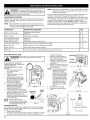
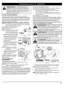
SPARK
ARRESTOR NOTE
The purpose of safety symbols is to attract your attention to possible
dangers. The safety symbols, and their explanations, deserve your
careful attention and understanding. The safety warnings do not by
themselves eliminate any danger. The instructions or warnings they
give are not substitutes for proper accident prevention measures.
SYMBOL
SAFETY
ALERT: Indicates danger, warning or
caution. Attention is required in order to avoid serious
personal injury. May be used in conjunction with other
symbols or pictographs.
DANGER:
Failure to obey a safety warning will result
in serious injury to yourself or to others. Always follow
the safety precautions to reduce the risk of fire, electric
shock and personal injury.
NOTE: For users on U.S. Forest Land and in the states of
California, Maine, Oregon and Washington. All U.S. Forest Land
and the state of California (Public Resources Codes 4442 and 4443),
Oregon and Washington
require, by law that certain internal
combustion engines operated on forest brush and/or grass-covered
areas be equipped with a spark arrestor, maintained in effective
working order, or the engine be constructed,
equipped
and
maintained for the prevention of fire. Check with your state or local
authorities for regulations pertaining to these requirements. Failure to
follow these requirements could subject you to liability or a fine. This
unit is factory equipped
with a spark arrestor.
If it requires
replacement,
ask your LOCAL SERVICE DEALER to install the
Accessory Part #753-05900 Muffler Assembly.
CALIFORNIA
PROPOSITION
MEANING
WARNING:
Failure to obey a safety warning can
result in injury to yourself and others. Always follow the
safety precautions to reduce the risk of fire, electric
shock and personal injury.
CAUTION:
Failure to obey a safety warning may result
in property damage or personal injury to yourself or to
[
others. Always follow the safety precautions to reduce
the r sk of f re, e ectr c shock and persona
65 WARNING
NOTE:
njury.
Advises you of information or instructions vital to the
operation or maintenance of the equipment.
Model Number
THE ENGINE EXHAUST FROM THIS PRODUCT CONTAINS
CHEMICALS KNOWN TO THE STATE OF CALIFORNIA TO
CAUSE CANCER, BIRTH DEFECTS OR OTHER
REPRODUCTIVE HARM.
Read the Operator's Manual and follow all warnings and safety
instructions. Failure to do so can result in serious injury to the
operator and/or bystanders.
FOR QUESTIONS,
CALL 1-800-659-5917
Seria_mber
_
S/N :
Parent Part Number
\MODEL:
TEM;
/
/
I
Copy the model and parent part number here:
Copy the serial number here:
* IMPORTANT SAFETY INSTRUCTIONS
READ ALL INSTRUCTIONS
BEFORE OPERATING
WARNING:
When using the unit, you must follow the
safety rules. Please read these instructions before
operating the unit in order to ensure the safety of the
operator and any bystanders. Please keep these
instructions for later use.
• Read the instructions carefully. Be familiar with the controls and
proper use of the unit.
• Do not operate this unit when tired, ill, or under the influence of
alcohol, drugs, or medication.
• Children and teens under the age of 15 must not use the unit,
except for teens guided by an adult.
• All guards and safety attachments must be installed properly
before operating the unit.
• Inspect the unit before use. Replace damaged parts. Check for fuel
leaks. Make sure all fasteners are in place and secure. Replace
parts that are cracked, chipped, or damaged in any way. Do not
operate the unit with loose or damaged parts.
• Carefully inspect the area before starting the unit. Remove all
debris and hard or sharp objects such as glass, wire, etc.
2
*
• Clear the area of children, bystanders, and pets. At a minimum,
keep all children, bystanders, and pets outside a 50 feet (15 m.)
radius; there still may be a risk to bystanders from thrown objects.
Bystanders should be encouraged to wear eye protection. If you
are approached, stop the unit immediately.
• Squeeze the throttle control and check that it returns automatically to
the idle position. Make all adjustments or repairs before using unit.
SAFETY WARNINGS FOR GAS UNITS
vapors
can explode
if ignited.
Takeflammable,
the following
WARNING:
Gasoline
is highly
and its
precautions:
• Store fuel only in containers specifically designed and approved
for the storage of such materials.
• Avoid creating a source of ignition for spilled fuel. Do not start the
engine until fuel vapors dissipate.
• Always stop the engine and allow it to cool before filling the fuel
tank. Never remove the fuel tank cap or add fuel when the engine
is hot. Never operate the unit without the fuel cap securely in
place. Loosen the fuel tank cap slowly to relieve any pressure in
the tank.
I
I
• Add fuel in a clean, well-ventilated outdoor area where there are
no sparks or flames. Slowly remove the fuel cap only after
stopping engine. Do not smoke while fueling or mixing fuel. Wipe
up any spilled fuel from the unit immediately. Always wipe unit
dry before using.
• Move the unit at least 30 feet (9.1 m) from the fueling source and site
before starting the engine. Do not smoke. Keep sparks and open
flames away from the area while adding fuel or operating the unit.
WHILE OPERATING
• Never start or run the unit inside a closed room or building.
Breathing exhaust fumes can kill. Operate this unit only in a wellventilated outdoor area.
• Wear safety glasses or goggles that are marked as meeting ANSI
Z87.1-1989 standards and are marked as such. Wear ear/hearing
protection when operating this unit.
• Never run the unit without the the proper equipment attached.
• To reduce the risk of hearing loss associated with sound level(s),
always wear ear/hearing protection when operating this unit.
• Wear heavy long pants, boots, gloves, and a long sleeve shirt. Do
not wear loose clothing, jewelry, short pants, sandals or go
barefoot. Secure hair above shoulder level.
• Use the unit only in daylight or good artificial light.
• Keep outside surfaces free from oil and fuel.
• Avoid accidental starting. Be in the starting position whenever
pulling the starter rope. The operator and unit must be in a stable
position while starting. Refer to Starting/Stopping Instructions.
• Do not set unit on any surface except a clean, hard area while
engine is running. Debris such as gravel, sand, dust, grass, etc.
could be picked up by the air intake and thrown out by the
discharge opening, damaging unit, property, or causing serious
injury to bystanders or operator.
• Use the right tool. Only use this tool for its intended purpose.
• Do not force unit. It will do the job better and with less likelihood of
injury at a rate for which it was designed.
• Do not overreach or use from unstable surfaces such as ladders,
trees, steep slopes, rooftops, etc. Always keep proper footing and
balance.
• Always hold the unit with a firm grip when operating.
• Keep hands, face, and feet away from all moving parts. Do not
touch or try to stop the impeller when it is rotating. Do not operate
without guards in place.
• Do not put any object into openings. Do not use with any opening
blocked; keep free of dirt, debris, and anything that may reduce
the air flow.
• Do not touch the engine or muffler. These parts get extremely hot
from operation, even after the unit is turned off.
• Do not operate the engine faster than the speed needed to do the
job. Do not run the engine at high speed when not in use.
• Always stop the engine when operation is delayed or when walking
from one location to another.
• Stop the engine for maintenance, repair, to install or remove the
blower tubes. The unit must be stopped and the impeller no longer
turning to avoid contact with the rotating blades.
• If you strike or come into contact with a foreign object, stop the
engine immediately and check for damage. Do not operate before
repairing damage. Do not operate the unit with loose or damaged
parts.
• Use only genuine factory replacement parts and accessories for
this unit. These are available from your authorized service dealer.
Use of any unauthorized parts or accessories could lead to serious
injury to the user or damage to the unit, and void your warranty.
• To reduce fire hazard, replace faulty muffler and spark arrestor.
Keep the engine and muffler free from grass, leaves, excessive
grease or carbon build up.
• Never point the blower or blowing debris in the direction of people,
animals, or in the direction of windows. Always direct the blowing
debris away from people, animals, and windows. Use extra caution
when blowing debris near solid objects such as trees, automobiles,
walls, etc.
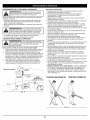
OTHER SAFETY WARNINGS
• Never store the unit, with fuel in the tank, inside a building where
fumes may reach an open flame (pilot lights, etc.) or sparks
(switches, electrical motors, etc.).
• Allow the engine to cool before storing or transporting. Be sure to
secure the unit while transporting.
• Store the unit in a dry place, either locked up or up high to prevent
unauthorized use or damage. Keep out of the reach of children.
• Never douse or squirt the unit with water or any other liquid. Keep
handles dry, clean, and free from debris. Clean after each use,
see Cleaning and Storage instructions.
• Keep these instructions. Refer to them often and use them to
instruct other users. If you loan this unit to others, also loan these
instructions to them.
SPECIAL NOTE: Exposure to vibrations through prolonged use of
gasoline powered hand tools could cause blood vessel or nerve
damage in the fingers, hands, and joints of people prone to
circulation disorders or abnormal swelling. Prolonged use in cold
weather has been linked to blood vessel damage in otherwise healthy
people. If symptoms occur such as numbness, pain, loss of strength,
change in skin color or texture, or loss of feeling in the fingers, hands
or joints, discontinue use of this tool and seek medical attention. An
anti-vibration system does not guarantee avoidance of these
problems. Users who operate power tools on a regular basis must
closely monitor their physical condition and the condition of this tool.
SAVE THESE INSTRUCTIONS
• SAFETY
AND INTERNATIONAL
SYMBOLS
•
This operator's manual describes safety and international symbols and pictographs that may appear on this product.
manual for complete safety, assembly, operating and maintenance and repair information.
SYMBOL
MEANING
SYMBOL
Read the operator's
MEANING
Indicates danger, warning or caution. May be used in
• conjunction
AFETY ALERT
with other
SYMBOL
symbols or pictographs.
• READ OPERATOR'S
MANUAL
WARNING:
Read
thesafety
operator's
manual(s)
and to
follow all warnings
and
instructions.
Failure
do so can result in serious injury to the operator
and/or bystanders.
• WEAR EYE AND HEARING PROTECTION
WARNING:
Thrown objects and loud noise can
cause severe eye injury and hearing loss. Wear eye
protection meeting ANSI Z87.1-1989 standards and
ear protection when operating this unit. Use a full
face she d when needed.
• KEEP BYSTANDERS AWAY
,L_'_;_;_'._I WARNING:
Keepaii bystanders, especially
children and pets, at !east 50 feet (15 m)from the
operating area.
WARNING:
Always use clean, fresh unleaded fuel.
I" UNLEADED FUEL
• OIL
_
Refer to operator's
manual for the proper type of oil.
CRAFTSMAN FULL WARRANTY
If this Craftsman product fails due to a defect in material or workmanship within two years from the date of purchase, return it to any Sears store,
Parts and Repair Service Center, or other Craftsman outlet in the United States for free repair (or replacement if repair proves impossible).
This warranty applies for only 90 days if this product is ever used for commercial or rental purposes.
This warranty covers ONLY defects in materal and workmanship. Sears will NOT pay for:
•
Expendable items that can wear out from normal use within the warranty period, such as cutting line, filters or spark plugs.
•
Repairs necessary because of accident or failure to operate or maintain the product according to all supplied instructions.
•
Preventive maintenance, or repairs necessary due to improper fuel mixture, contaminated or stale fuel.
This warranty gives you specific legal rights, and you may also have other rights which vary from state to state.
Sears, Roebuck and Co., Hoffman Estates, IL 60179
Repair Protection Agreements
Congratulations on making a smart purchase. Your new Craftsman® product is designed and manufactured for years of dependable
operation. But like all products, it may require repair from time to time. That's when having a Repair Protection Agreement can save you
money and aggravation.
Here's what the Repair Protection Agreement* includes:
[]
Expert service by our 10,000 professional repair specialists
[]
Unlimited service and no charge for parts and labor on all covered repairs
[]
Product replacement up to $1500 if your covered product can't be fixed
[]
Discount of 10% from regular price of service and related installed parts not covered by the agreement; also, 10% off regular price of
preventive maintenance check
[]
Fast help by phone - we call it Rapid Resolution - phone support from a Sears representative. Think of us as a "talking owner's manual."
Once you purchase the Repair Protection Agreement, a simple phone call is all that it takes for you to schedule service. You can call anytime
day or night, or schedule a service appointment online.
The Repair Protection Agreement is a risk-free purchase. If you cancel for any reason during the product warranty period, we will provide a
full refund. Or, a prorated refund any time after the product warranty period expires. Purchase your Repair Protection Agreement today!
Some limitations and exclusions apply. For prices and additional information
in the U.S.A. call 1-800-827-6655.
*Coverage in Canada varies on some items. For full details call Sears Canada at 1-800-361-6665.
Sears Installation Service
For Sears professional installation of home appliances, garage door openers, water heaters, and other major home items, in the U.S.A. or
Canada call 1-800-4-MY-HOME
®.
4
I
DO not toUch a Rot muff!er;gear
housing or cylinderl You may get burned. These parts I
get extremelY hot from operation, They remain hot f0rl
a short time after the unit is turned off.
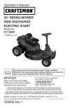
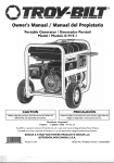
APPLICATIONS
Cleaning
yards,garages,
driveways,
porches,
patios,
around
walls,fences
andmore.
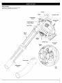
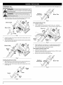
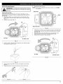
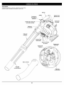
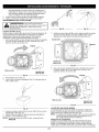
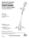
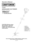
Handle
Trigger
\
On/Off Stop
Control
Air Filter Cover
/
Starter Rope
Grip
Variable Speed
Cruise Control
Spark Plug
Blower
Tube
Muffler
Cover
Oil Filler Cap
Primer
Bulb
Red Choke
Lever
/
Concentrator
Curved_/
/
Fuel
Cap
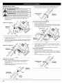
ASSEMBLING
UNIT
3.
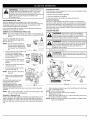
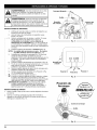
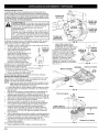
Twist the nozzle clockwise over the blower tube until tight (Fig. 4).
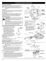
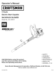
Installing Blower Tube
WARNING:
To prevent serious personal injury, stop
theor
removingengine
andtubes.a
ow the mpe er to stop before attach ng
_ll
1.
damage
to the unit,
the blower
tubepersonal
must beinjury
installed
WARNING:
To prevent
serious
or
while operating this unit.
Nozzle or
Curved Tube
I
Blower Tube
I
Align the bump on the end of the blower tube with the bump
slot on the bottom end of the blower outlet (Fig. 1).
Fig. 4
Blower Outlet
Removing the Blower Tube
1. Hold the unit firmly.
2.
Insert a flathead screwdriver into the Tube Lock. Twist the
screwdriver counterclockwise
1/4 turn and hold it there (Fig. 5).
Blower Tube
Bump
Slot
Bump
Tu
Fig. 1
2.
3.
Insert the bump on the blower tube into the bump slot on the
blower outlet (Fig. 1).
Twist the blower tube clockwise inside the blower outlet until the
bump locks into place (Fig. 2).
Fig. 5
3.
Blower Outlet
4.
While holding the screwdriver in a counterclockwise
grasp the blower tube and twist it counterclockwise
Pull the blower tube from the blower outlet.
Removing the Nozzle/Curved Tube
1. Hold the blower tube firmly.
2. Grasp the nozzle and twist it counterclockwise
unlocks from the blower tube (Fig. 6).
3.
Remove the nozzle from the blower tube.
Blower
Tube
\
position,
(Fig. 5).
until the nozzle
Fig. 2
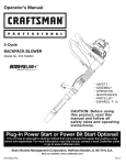
Installing Nozzle/Curved Tube
1. Align the bump on the end of the blower tube with the bump
slot on the bottom end of the blower outlet (Fig. 3).
2.
Nozzle or
Curved Tube
Blower Tube
Insert the bump on the blower tube into the bump slot on the
nozzle (Fig. 3).
Fig. 6
Blower
Tube
Bump
Nozzle
Bump
Slot
Fig. 3
6
WARNING:
OVERFILLING OIL CRANKCASE MAY
I
CAUSE SERIOUS PERSONAL INJURY. Check and
maintain the proper oil level in the crank case; it is
important and cannot be overemphasized. Check the oil
before each use and change it as needed. See
Changing the Oil.
I
RECOMMENDED OIL TYPE
Using the proper type and weight of oil in the crankcase is
extremely important. Check the oil before each use and change the
oil regularly. Failure to use the correct oil, or using dirty oil, can
cause premature engine wear and failure.
Use a high-quality SAE 30 weight oil of API (American Petroleum
Institute) service class SF, SG, SH.
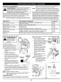
ADDING OIL TO CRANKCASE: INITIAL USE
Using Blended Fuels
If you choose to use a blended fuel, or its use is unavoidable, follow
recommended precautions:
• Always use fresh unleaded gasoline
• Use a gas stabilizer fuel additive
• Drain tank and run the engine dry before storing unit
Using Fuel Additives
The use of a gas stabilizer will inhibit corrosion and minimize the
formation of gum deposits. Using a fuel additive can keep fuel from
forming harmful deposits in the carburetor for up to six (6) months.
Add 0.8 oz. (23 ml.) of fuel additive per gallon of fuel according to
the instructions on the container. NEVER add fuel additives directly
to the unit's gas tank.
FUELING THE UNIT
WARNING:
Add fuel in a clean, well ventilated
outdoor area. Wipe up any spilled fuel immediately.
Avoid creating a source of ignition for spilt fuel. Do not
start the engine until fuel vapors dissipate.
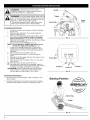
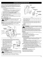
NOTE: This unit is shipped without oil. In order to avoid damage to
the unit, put oil in the crankcase before you attempt to start
the unit.
Your unit is supplied with one 2.03
fluid oz. (60 ml) bottle of SAE 30 SF,
SG, SH oil (Fig. 7).
NOTE: Save the empty oil bottle. It
can be used to measure the
correct amount during future
oil changes. See Changing the
Oil.
1,
2,
WARNING:
Gasoline is extremely flammable. Ignited I
vapors may explode. Always stop the engine and allow it
to cool before filling the fuel tank. Do not smoke while
I
filling the tank. Keep sparks and open flames at a
d stance from the area.
Remove the fuel cap (Fig. 10).
Unscrew the top of the bottle of oil
and remove the paper seal
Oil Fill
covering the opening. Replace
the top. Next, cut the tip off the
Plug
funnel spout (Fig. 7).
O-Rinc
Tip unit so that the back of the
engine is facing up in a vertical
Oil Fill
position.
Hole
3,
Remove the oil fill plug from the
crankcase (Fig. 8).
4.
Pour the entire bottle of oil into
the oil fill hole (Fig. 9).
NOTE:
WARNING:
Remove fuel cap slowly to avoid injury
from fuel spray. Never operate the unit without the fuel
cap securely in place.
Fig. 8
Gas Can
Spout
fJ
Never add oil to the fuel or
fuel tank.
5.
Wipe up any oil that may have
spilled and reinstall the oil fill
plug.
Check oil before each use and
change as needed. Refer to
Checking the Oil Level.
J
RECOMMENDED
FUEL TYPE
Fig. 9
Old fuel is the primary reason for
improper unit performance. Be sure to use fresh, clean, unleaded
gasoline.
NOTE: This is a four cycle engine. In order to avoid damage to the
unit, do not mix oil with gasoline.
Definition of Blended Fuels
Today's fuels are often a blend of gasoline and oxygenates such as
ethanol, methanol or MTBE (ether). Alcohol-blended fuel absorbs
water. As little as 1% water in the fuel can form acids when stored.
Use fresh fuel (less than 60 days old), when using alcohol-blended
fuel.
Fuel Cap
FuelTank
Fig. 10
2.
Place the gas container's spout into the fill hole on the fuel tank
(Fig. 10) and fill the tank.
NOTE: Do not overfill the tank.
3. Wipe up any gasoline that may have spilled.
4.
Reinstall the fuel cap.
5.
Move the unit at least 30 ft. (9.1 m) from the fueling source and
site before starting the engine.
NOTE: Dispose of the old gasoline in accordance to Federal, State
and Local regulations.
I
On/Off
ventilated outdoor area. Carbon monoxide exhaust
fumes can be lethal
in a this
confined
area.in a wellI WARNING:
Operate
unit only
I_
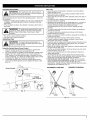
WARNING:
Avoid accidental starting. Make sure you
are in the starting position when pulling the starter rope
(Fig. 13). To avoid serious injury, the operator and unit
must be in a stable position while starting.
To avoid serious personal injury, make sure that the
blower tube is locked in place or firmly installed.
Trigger
Choke
Lever
Primer Bulb
Y
t
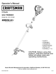
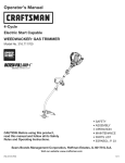
STARTING INSTRUCTIONS
Check the oil level in the crankcase. Refer to Checking
the Oil Level.
2. Fill the fuel tank with fresh, clean unleaded gasoline.
Refer to Fueling the Unit.
Fully press and release the primer bulb 10 times, slowly.
Some amount of fuel should be visible in the primer
bulb and fuel lines (Fig. 11). If you can't see fuel in the
bulb, press and release the bulb as many times as it takes
before you can see fuel in it.
4. Place the choke lever in Position 1 (Fig. 12).
NOTE: The unit should be started in idle speed. Do not
squeeze the trigger while starting (Fig. 13).
5. Crouch in the starting position (Fig. 13) and pull the
starter rope out until you feel some resistance. This is
usually around 2-4 inches. Pull 4 times in smooth and
rapid pulls.
6. Place the choke lever in Position 2 (Fig. 13).
7,
Pull the starter rope briskly 1 to 4 times to start the
engine.
8. Squeeze the throttle trigger and allow the engine to warm
up for 30 to 60 seconds.
9. Place the choke lever in Position 3 (Fig. 13). The unit is
ready for use.
.................
IF... the engine does not start, go back to step 3.
IF... the engine fails to start after a few attempts, place the
choke lever in Position 3 and pull the starter rope briskly 3
to 8 times. The engine should start. If not, repeat.
HOT RESTART: If the unit is already hot; place the choke
lever in Position 2, making sure to NOT squeeze the
throttle trigger, and follow steps 7 thru 9 above.
1,
Fig. 11
I{I NH
Primer Bulb
Position 3
®
®G
Position 1
Position 2
Fig. 12
STOPPING INSTRUCTIONS
1.
Release your hand from the trigger. Allow the engine to cool
down by idling.
2.
Press the On/Off Stop Control switch in the OFF (O) position
and hold until the engine comes to a complete stop (Fig. 11).
Starting Position
__ncredi=PulJ
Starter Rope
Trigger
Fig. 13
8
/
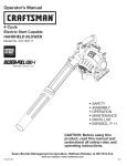
HOLDING THE BLOWER
the left side of the unit to operate it as shown in figure 15
WARNING:
After starting
unit, always stand on
to keep from blocking
the air the
intake.
I
Before operating the unit, stand in the operating position. Check for
the following:
• Operator is wearing proper clothing, such as boots, safety glasses
or goggles, ear/hearing protection, gloves, long pants and long
sleeve shirt
• If the conditions are dusty, the operator is wearing a dust mask or
face mask
WARNING:
To avoid serious personal injury, wear
goggles or safety glasses at all times when operating
this unit. Wear a face mask or dust mask in dusty
locations.
• The unit is in good working condition
• The tubes are in place and secure
OPERATING TIPS
damage to the unit, make sure blower tubes are in place
WARNING:
To prevent
before you operate
the unit. serious personal injury or
Using the Variable Speed Cruise Control
1. Once the engine has started and warmed up, squeeze the
trigger to accelerate the unit as needed (Fig. 14).
2. For longer periods of operation and to eliminate possible finger
fatique, move the variable speed cruise control toward the
FAST position to incrementally increase or maintain the unit's
engine speed (Fig. 14). When the variable speed cruise control
is pressed, the trigger will recede into the handle.
3. To decrease engine speed, move the variable speed cruise
control to the SLOW position and the trigger will return to idle
(Fig. 14).
I
I
Other Tips
• Assure the unit is not directed at anybody or any loose debris
before starting the unit.
• Verify that the unit is in good working condition. Make sure the
tubes are in place and secure.
• Always hold the unit securely when operating. Keep a firm grip on
the handle.
• To reduce the risk of hearing loss associated with sound level(s),
hearing protection is required.
• Operate power equipment only at reasonable hours-- not early in
the morning or late at night when people might be disturbed.
Comply with times listed in local ordinances. Usual
recommendations are 9:00 am to 5:00 pm, Monday through
Saturday.
• To reduce noise levels, limit the number of pieces of equipment
used at any one time.
• To reduce noise levels, operate power blowers at the lowest
possible speed to do the job.
• Check your equipment before operation, especially the muffler, air
intakes and air filters.
• Use rakes and brooms to loosen debris before blowing.
• In dusty conditions, slightly dampen surfaces or use a mister
attachment when water is available.
• Conserve water by using power blowers instead of hoses for many
lawn and garden applications, including areas such as screens,
patios, grills, porches, and gardens.
• Watch out for children, pets, open windows or freshly washed cars,
and blow debris safely away.
• Use the curved nozzle extension so the air stream can work close
to the ground (p. E19, no. 25).
• Clean up after using blowers and other equipment. Dispose of
debris appropriately.
• Use the blower for trees, shrubs, flower beds and hard-to-clean
areas. Also use the unit around buildings, walls, overhangs, fences
and screens, and for other normal cleaning procedures.
• Hold the blower with the right hand. Do not stand on the right
side of the blower when operating the unit (Fig. 14). If you do, you
will be blocking the air intake and this will affect the unit's
performance. Instead, be sure to stand on the left side of the unit to
maximize the unit's efficiency (Fig. 15).
INCORRECT POSITION
Cruise
Control
__
____._/(Idle--
CORRECT POSITION
I rlggerposition)
Fig. 14
Fig. 15
WARNING:
Toprevent
serious
injury,
neverperform
maintenance
orrepairs
withunitrunning.
Always
service
andrepairacoolunit.Disconnect
thesparkplugwireto
ensure
thattheunitcannot
start.
MAINTENANCE SCHEDULE
Perform these required maintenance procedures at the frequency
stated in the table. These procedures should also be a part of any
seasonal tune-up.
NOTE:
Some maintenance procedures may require special tools or
skills. If you are unsure about these procedures take your unit
to a Sears or other qualified service dealer.
NOTE:
Maintenance, replacement, or repair of the emission control
devices and system may be performed by a Sears or other
qualified service dealer.
In order to assure peak performance of your engine, inspection of
the engine exhaust port may be necessary after 50 hours of
operation. If you notice lost RPM, poor performance or general lack
of acceleration, this service may be required. If you feel your engine
is in need of this inspection, refer service to a Sears or other
qualified service dealer for repair. DO NOT attempt to perform this
process yourself as engine damage may result from contaminants
involved in the cleaning process for the port.
FREQUENCY
MAINTENANCE
Before starting engine
Fill fuel tank with fresh fuel
Check oil
p. 7
p. 10
Every 10 hours
Clean and re-oil air filter
p. 11
1st change at 10 hours
2nd change at 40 hours
Every 40 hours after
Change oil
Change oil
Clean spark arrestor and change oil
p. 10
p. 10
p. 13 & 10
10 hours on new engine
Every 40 hours
Check rocker arm to valve clearance and adjust
Check rocker arm to valve clearance and adjust
p. 12
p. 12
Every 40 hours
Check spark plug condition and gap
p. 13
200 hours
Take unit to a Sears or other qualified service center for service
CHECKING
REQUIRED
THE OIL LEVEL
WARNING:
Wear gloves to prevent injury when
handling unit.
The importanceof checking and
maintaining the proper oil level in the
r
crankcase cannot be
overemphasized. Check oil before
4
each use:
_"
U
1. Stop the engine and allow
oil to drain into the
crankcase.
2.
Place the engine on a level
surface (Fig. 16).
3.
Clean the area around the oil
plug before removing it. Keep
|
dirt, grass clippings, and other
debris out of the engine.
4.
Remove the oil fill plug.
5.
Look into the oil fill hole (use a
flashlight if needed). The oil
Fig. 16
should be just touching the
innermost thread (Fig. 17).
6.
If the oil level is not touching the
Oil Fill
innermost thread on the oil fill hole,
Innermost
Hole
add a small amount of oil to the oil
Thread
fill hole and recheck (Fig. 17).
Repeat this procedure until the oil
level reaches the innermost thread
on the oil fill hole.
NOTE: Do not overfill the unit.
NOTE: Make sure the O-ring is in place
on the oil fill plug when checking -Fig. 17
and changing the oil (Fig. 18).
CHANGING THE OIL
For a new engine, change the oil after the first 10 hours of operation.
Change the oil while the engine is still warm. The oil will flow freely
and carry away more impurities.
1. Remove the oil fill plug.
2.
Pour the oil out of the oil fill hole and into a container by tipping
the unit to a vertical position (Fig. 19). Allow ample time for
10
SEE
complete drainage.
Wipe up any oil residue on
the unit and clean up any oil
that may have spilled.
Dispose of the oil according
to Federal, State and local
regulations.
4.
Refill the crankcase with 2.03
fluid ounce (60 ml) of SAE 30
SF, SG, SH oil.
NOTE: Use the bottle and spout
saved from initial use to
measure the correct
amount of oil. The fill line
on the label on the bottle
measures approximately
2.03 ounces (60 ml) (Fig.
20). Check the level, See
Checking the Oil Level. If
the level is low, add a
small amount of oil and
recheck. Do not overfill
(Fig. 17).
5.
Replace the oil fill plug.
6.
Reconnect the spark plug
boot.
3.
Oil Fill Plug _'_
_ _
°1'
Fig. 18
Fig. 19
Fill Level
I 4-Cyde
Motor
-L
Fig. 20
Oil
Fill Line
AIR FILTER MAINTENANCE
I_
6.
Replace the filter (Fig. 25).
NOTE: If the unit is operated without the air filter, you will VOID
the warranty.
I
I WARNING:
avoid
serious
personal
alwaysor
turrniYou_.unt offToand
a ow
tto coo
beforeinjury,
you cean
Back Plate
Cleaning the Air Filter
Clean and re-oil the air filter every 10 hours of operation. It is an
important item to maintain. Failure to maintain the air filter will VOID
the warranty.
1. Open the air filter cover. Push the tab on the left side of the
cover inward. Then pull the air filter cover out and to the right
(Fig. 21).
2. Remove the air filter (Fig. 21).
Slots
Tab
Back Plate Slot
Fig. 25
7.
8.
9.
Reinstall the air filter cover. Position the hooks on the right side
of the air filter cover into the slots at the right side of the back
plate (Fig. 25).
Swing the cover to the left until the tab on the air filter cover
snaps into place in the slot on the back plate (Fig. 26).
Replace the fuel cap if it was removed.
Air Filter
Tab
Air Filter Cover
Fig. 21
3,
Wash the filter in detergent and water (Fig. 22). Rinse the filter
thoroughly and allow it to dry.
Air Filter
Air Filter Cover
Fig. 26
Fig. 22
4,
5.
Apply enough clean SAE 30 motor oil to lightly coat the filter
(Fig. 23).
Squeeze the filter to spread and remove excess oil (Fig. 24).
Fig. 23
Fig. 24
11
IDLE SPEED ADJUSTMENT
The idle speed of the engine is adjustable. An idle adjustment screw is
between the air filter cover and the engine starter housing (Fig. 27).
NOTE: Careless adjustments can seriously damage your unit. A Sears
or other qualified service dealer should make carburetor
adjustments.
Check Fuel
Old fuel is usually the reason for improper unit performance. Drain
and refill the tank with fresh fuel prior to making any adjustments.
Refer to Oil and Fuel Information.
Clean Air Filter
The condition of the air filter is important to the operation of the unit. A
dirty air filter will restrict air flow. This is often mistaken for an out of
adjustment carburetor. Check the condition of the air filter before
adjusting the idle speed screw. Refer to Air Filter Maintenance.
Adjust Idle Speed Screw
WARNING:
Muffler
Cover
\
Starter
Housing
Screws (2)
Starter
Housing
(4)
Muffler Cover
Screws (2)
This unit will need to be running during
idle speed adjustment. Wear protective clothing and
observe all safety instructions to prevent serious
personal injury.
Also, DO NOT set unit on any surface except a clean,
hard area while starting or performing any adjustments.
Debris, such as gravel, sand, dust, grass, etc., could be
thrown by the blower tube and damage property or
cause serious injury to bystanders or operator.
If, after checking the fuel and cleaning the air filter, the engine still will not
idle, adjust the idle speed screw as follows:
1. Start the engine and let it run at a high
Idle Speed
idle for a minute to warm up. Refer to
Few
Starting/Stopping Instructions.
2. Release the trigger and let the engine
idle. If the engine stops, insert a small
phillips screwdriver in between the Air
Filter Cover and the Engine Cover (Fig.
27). Turn the idle speed screw in,
clockwise, 1/8 of a turn at a time (as
needed) until the engine idles smoothly.
Checking the fuel, cleaning the air filter, and
adjusting the idle speed should solve most
engine problems. If not and all of the
following are true:
-Fig. 27 -• the engine will not idle
• the engine hesitates or stalls on acceleration
• there is a loss of engine power
take the unit to a Sears or other qualified service dealer.
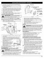
ROCKER ARM CLEARANCE
This requires disassembly of the engine. If you feel unsure or unqualified
to perform this, take the unit to a Sears or other qualified service dealer.
NOTE: Inspect the valve to rocker arm clearance with a feeler
gauge after the first 10 hours of operation and every 40
hours of operation.
• The engine must be cold when checking or adjusting the rocker
arm clearance.
• This task should be performed inside, in a clean, dust free area.
1. Remove the 2 muffler cover screws with a flat blade or T-25
Torx head screwdriver (Fig. 28), then remove the cover.
2. Remove the 6 starter housing screws with flat blade or T-25 Torx
head screwdriver (Fig. 28), then remove the housing.
NOTE: Make sure to store the screws so that they can be
reinstalled into their original holes.
3. Disconnect the spark plug wire.
4. Clean dirt from around the spark plug. Remove the spark plug from
the cylinder head by turning a 5/8 in. socket counterclockwise.
5. Clean dirt from around the rocker arm cover. Remove the screw
holding the rocker arm cover with a large flat blade screwdriver or
Torx T-25 bit (Fig. 29). Remove the rocker arm cover and gasket.
6. Turn the flywheel slowly to bring the piston to the top of its
travel (known as top dead center). Check that:
12
Fig. 28
• The piston is at the top of its travel
by looking in the spark plug hole
(Fig. 30)
• Both rocker arms move freely, and
both valves are closed.
If these statements are not true, repeat
this step.
7. Slide the feeler gauge between
the rocker arm and the valve
return spring. Measure the
clearance between the valve stem
and rocker arm (Fig. 30 & 31).
Measure both the intake and
exhaust valves.
Arm
Spark
Plug Hole
Cover
Fig. 29
Adjusting Nuts
INTAKE
Rocker Arms
O-Ring
Feeler Gauge
Fig. 30
Adjusting Nut
Rocker Arm
.003-.006 in.
(0.076-0.152 mm)
Feeler
Valve Stem
Fig. 31
Gauge
Therecommended
clearance
forbothintake
andexhaust
is.003- .006
in.(.076
- 0.152
mm).Useastandard
automotive
.005in.(0.127
mm)
feeler
gauge.
Thefeeler
gauge
should
slidebetween
therocker
arm
andvalve
stemwithaslightamount
ofresistance,
without
binding.
See
Figures
30and31.
8. Iftheclearance
isnotwithinspecification:
a.Turntheadjusting
nutusinga5/16inch(8mm)wrenchornut
driver(Fig.31).
• Toincrease
clearance,
turntheadjusting
nutcounterclockwise.
• Todecrease
clearance,
turntheadjusting
nutclockwise.
b.Recheck
bothclearances,
andadjustasnecessary.
9. Reinstall
therockerarmcoverusinganewgasket(Fig.29).
Torque
thescrewto: 20-30in-lb(2.2-3.4
N•m}.
10. Check
thesparkplugandreinstall.
SeeReplacing the Spark Plug.
11. Reinstall the spark plug wire.
12. Reinstall the engine cover. Check alignment of the cover before
tightening the screws. Tighten screws.
NOTE: Make sure that the screws are reinstalled into their original
holes (Fig. 28).
REPLACING THE SPARK PLUG
electrodes.
engineblast,
couldscrape,
damage
CAUTION: GritDoin the
not sand
or the
clean
cylinder.
Spark Arrestor
Screen
Spark Arrestor
Cover
T-25 or 3/8-inch
ex Screw
1/4-inch
Hex Screw
Fig. 34
I
Use a replacement part number 753-05784 or Champion spark plug
#RDZ4N. The correct spark gap is 0.025 in. (0.635 mm). Remove the
plug after every 40 hours of operation and check its condition.
1. Stop the engine and allow it to cool.
2. Insert a flat blade screwdriver under the spark plug cover and
pry open (Fig. 32).
wrench, remove the screws attaching the spark arrestor cover
to the muffler (Fig. 34).
3.
Pull the the spark arrestor cover out of the muffler. Remove the
spark arrestor cover.
4.
Remove the spark arrestor screen from the spark arrestor cover.
5.
Clean the spark arrestor screen with a wire brush or replace it.
6.
Reinstall the spark arrestor screen, spark arrestor cover, and
screws.
7. Reinstall the muffler cover.
CLEANING
I _
Spark Plug
Cover
---.
Muffler
_Screwdriver
Fig. 32
3.
4.
Grasp the plug wire firmly and pull the cap from the spark plug.
Clean dirt from around the spark plug. Remove the spark plug
from the cylinder head by turning a
5/8 in. socket counterclockwise.
5. Replace cracked, fouled or dirty
spark plug. Set the spark gap at
0.025 in. (0.635 mm) using a feeler
gauge (Fig. 33).
6. Install a correctly-gapped
spark
plug in the cylinder head. Turn the
5/8 in. socket clockwise until snug.
7,
Reinstall the spark plug cover.
If using a torque wrench, torque to:
|
110-120 in.•lb. (12.3-13.5 N•m)
Do not over tighten.
-Fig. 33
SPARK ARRESTOR MAINTENANCE
turn
your unit offToand
allow
it to cool
beforeinjury,
you clean
WARNING:
avoid
serious
personal
alwaysorJI
do any maintenance on it.
JWARNING:
avoid
serious
personal
alwaysor
do any
on
it.
turn
yourmaintenance
un t offToand
a ow
t to coo
beforeinjury,
you cean
Use a small brush to clean off the outside of the unit. Do not use
strong detergents. Household cleaners that contain aromatic oils
such as pine and lemon, and solvents such as kerosene, can damage
plastic housing or handle. Wipe off any moisture with a soft cloth.
STORAGE
• Never store the unit with fuel in the tank where fumes may reach an
open flame or spark.
• Allow the engine to cool before storing.
• Lock up the unit to prevent unauthorized use or damage.
• Store the unit in a dry, well-ventilated area.
• Store the unit out of the reach of children.
LONG TERM STORAGE
1. Drain all gasoline from the gas tank into a container. Do not use
gas that has been stored for more than 60 days. Dispose of the
old gasoline in accordance to Federal, State, and Local
regulations.
2.
Start the engine and allow it to run until it stalls. This ensures that
all gasoline has been drained from the carburetor.
3. Allow the engine to cool. Remove the spark plug and put 5 drops
of high quality motor oil into the cylinder. Pull the starter rope
slowly to distribute the oil. Reinstall the spark plug.
NOTE: Remove the spark plug and drain all of the oil from the cylinder
before attempting to start the blower after storage.
4.
Change the oil, referring to Changing the Oil. Dispose of the old
oil in accordance to Federal, State and Local regulations.
5. Thoroughly clean the unit and inspect for any loose or damaged
parts. Repair or replace damaged parts and tighten loose screws,
nuts or bolts. The unit is ready for storage.
TRANSPORTING
• Allow the engine to cool before transporting.
• Secure the unit while transporting.
• Drain the gas tank before transporting.
• Tighten gas cap before transporting.
I
2[
Remove the muffler cover. See RockerArm Clearance.
With a 3/8-inch hex wrench or T-25 bit and a 1/4-inch hex
13
CAUSE
Empty
gasoline
tank
Primer
bulbwasn'tpressed
enough
Oldgasoline
Fouled
sparkplug
Plugged
sparkarrestor
ACTION
Fill fuel tank with new gasoline
Press primer bulb fully and slowly 10 times
Drain gas tank and add fresh gasoline
Replace the spark plug
Clean or replace spark arrestor
CAUSE
Air filter is plugged
Old fuel
ACTION
Replace or clean the air filter
Drain gas tank and add fresh gasoline
CAUSE
Old gasoline
Dirty air filter
Plugged spark arrestor
ACTION
Drain gas tank and add fresh gasoline
Clean or replace the air filter
Clean or replace spark arrestor
CAUSE
Old gasoline
Fouled spark plug
Plugged spark arrestor
ACTION
Drain gas tank and add fresh gasoline
Replace the spark plug
Clean or replace spark arrestor
NOTE:
For repairs beyond the minor adjustments listed above, contact your nearest Sears Parts & Repair center (1-800-4-MY-I-IOME
other qualified service dealer.
®) or
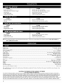
Engine Type ............................................................................................................................................................................
Air-Cooled, 4-Cycle
Displacement ..............................................................................................................................................................................
1.5 cu. in. (25 cc)
Blower Operating RPM ............................................................................................................................................................................
7,000 rpm
Idle Speed RPM ........................................................................................................................................................................
3,200 - 4,400 rpm
Ignition Type .......................................................................................................................................................
Electronic MAX FIRE IGNITION TM
Ignition Switch ...........................................................................................................................................................................
Momentary Switch
Valve clearance ................................................................................................................................................
0.003-0.006 in. (0.076-0.152 mm)
Spark Plug Gap ...................................................................................................................................................................
0.025 inch (0.635 mm)
Lubrication ..............................................................................................................................................................................................
SAE 30 Oil
Crankcase Oil Capacity ..................................................................................................................................................................
2.03 oz (60 ml)
Fuel .........................................................................................................................................................................................................
Unleaded
Carburetor .........................................................................................................................................................................
Diaphragm, All-Position
Starter .............................................................................................................................................................
Incredi-Pull TM Starting Auto Rewind
Muffler ........................................................................................................................................................................................
Baffled with Guard
Throttle ............................................................................................................................................................................................
Variable Speed
Fuel Tank Capacity ...........................................................................................................................................................................
14 oz (414 ml)
Approximate Unit Weight (No fuel) ........................................................................................................................................................
11 Ibs. (5 kg)
*All specifications are based on the latest product information
time without notice.
CALIFORNIA
available at the time of printing. We reserve the right to make changes at any
/ EPA EMISSION CONTROL WARRANTY STATEMENT
Your Warranty Rights and Obligations
The California Air Resources Board, the Environmental Protection Agency, and Sears Brands LLC (Sears) are pleased to explain the emission control system
warranty on your 2008 and later small off-road engine. In California and the 49 states, new small off-road engines must be designed, built and equipped to meet
the state's stringent anti-smog standards. Sears must warrant the emission control system on your small off-road engine for the periods of time listed below
provided there has been no abuse, neglect or improper maintenance of your small off-road engine. Your emission control system may include parts such as the
carburetor or fuel-injection system, the ignition system, and catalytic converter. Also included may be hoses, belts, connectors and other emission-related
assemblies. Where a warrantable condition exists, Sears will repair your small off-road engine at no cost to you including diagnosis, parts and labor. The 2008 and
later small off-road engines are warranted for two years. If any emission-related part on your engine is defective, the part will be repaired or replaced by Sears.
14
Owners Warranty Responsibilities
As the small off-road engine owner, you are responsible for the performance of the required maintenance listed in your operator's manual. Sears recommends
that you retain all receipts covering maintenance on your small off-road engine, but Sears cannot deny warranty solely for the lack of receipts or for your failure
to ensure the performance of all scheduled maintenance.
• As the small off-road engine owner, you should however be aware that Sears may deny you warranty coverage if your small off-road engine or a part has
failed due to abuse, neglect, improper maintenance or unapproved modifications.
• You are responsible for presenting your small off-road engine to a Sears Authorized Service Center as soon as a problem exists. The warranty repairs
should be completed in a reasonable amount of time, not to exceed 30 days.
If you have any questions regarding your warranty rights and responsibilities, you should call 1-800-4-MY-HOME
®.
Manufacturer's
Warranty Coverage
• The warranty period begins on the date the engine or equipment is delivered to the retail purchaser.
• The manufacturer warrants to the initial owner and each subsequent purchaser, that the engine is free from defects in material and workmanship which
cause the failure of a warranted part for a period of two years.
• Repair or replacement of warranted pa_will be performed at no charge to the owner at an Authorized Sears Service Center. For the nearest location please
contact Sears at: 1-800-4-MY-HOME
.
• Any warranted part which is not scheduled for replacement, as required maintenance or which is scheduled for only for regular inspection to the effect of
"Repair or Replace as Necessary" is warranted for the warranty period. Any warranted part which is scheduled for replacement as required maintenance will
be warranted for the period of time up to the first scheduled replacement point for that part.
• The owner will not be charged for diagnostic labor which leads to the determination that a warranted part is defective, if the diagnostic work is performed at
an Authorized Sears Service Center.
• The manufacturer is liable for damages to other engine components caused by the failure of a warranted part still under warranty.
• Failures caused by abuse, neglect or improper maintenance are not covered under warranty.
• The use of add-on or modified parts can be grounds for disallowing a warranty claim. The manufacturer is not liable to cover failures of warranted parts
caused by the use of add-on or modified parts.
• In order to file a claim, go to your nearest Authorized Sears Service Center. Warranty services or repairs will be provided at all Authorized Sears Service Centers.
• Any manufacturer approved replacement part may be used in the performance of any warranty maintenance or repair of emission related parts and will be
provided without charge to the owner. Any replacement part that is equivalent in performance or durability may be used in non-warranty maintenance or
repair and will not reduce the warranty obligations of the manufacturer.
Emission Warranty Parts List:
The following components are included in the emission-related warranty of the engine: air filter, carburetor, primer, fuel lines, fuel pick up/fuel filter, ignition
module, spark plug, and muffler. Valves and Cam are additionally included if your engine is a 4-Stroke Model.
CALIFORNIA
EVAPORATIVE EMISSION CONTROL WARRANTY STATEMENT
Your Warranty Rights and Obligations
The California Air Resources Board and Sears Brands LLC (Sears) is pleased to explain the evaporative emission control system's warranty on your 2008 model year and
later small off-road (equipment type) engine. In California, new equipment that use small off-engines must be designed, built, and equipped to meet the State's stringent
anti-smog standards Sears must warrant the evaporative emission control system on your small off-road Lawn & Garden engine for the period listed below provided
there has been no abuse, neglect or improper maintenance of your equipment. Your evaporative emission control system may include parts such as: carburetors, fuel
tanks, fuel lines, fuel caps, valves, canisters, filters, vapor hoses, clamps, connectors, and other associated components. For engines less than or equal to 80 cc, only
the fuel tank is subject to the evaporative emission control warranty requirements of this section. The displacement of your small off road engine is less than 80 cc.
Manufacturer's
Warranty Coverage
This evaporative emission control system is warranted for two years. If any evaporative emission-related
part on your equipment is defective, the part will be
repaired or replaced by Sears.
Owner's Warranty Responsibilities
• As the small off-road Lawn & Garden engine owner, you are responsible for performance of the required maintenance listed in your owner's manual. Sears
recommends that you retain all receipts covering maintenance on your Lawn & Garden Engine but Sears cannot deny warranty solely for the lack of receipts.
• As the small off-road Lawn & Garden engine owner, you should however be aware that the Sears may deny you warranty coverage if your fuel tank has
failed due to abuse, neglect, or improper maintenance or unapproved modifications.
• You are responsible for presenting your Lawn & Garden fuel tank to Sears distribution center or service center as soon as the problem exists. The warranty
repairs should be completed in a reas.._able
contact Sears at 1-800-4-MY-HOME
.
amount of time, not to exceed 30 days.
If you have a question regarding your warranty coverage,
you should
Defects Warranty Requirements
(a) The warranty period begins on the date the engine or equipment is delivered to an ultimate purchaser.
(b) General Evaporative Emissions Warranty Coverage. The fuel tank must be warranted to the ultimate purchaser and any subsequent owner that the
evaporative emission control system when installed was:
(1) Designed, built, and equipped so as to conform with all applicable regulations; and
(2) Free from defects in materials and workmanship that causes the failure of a warranted part for a period of two years.
(c) The warranty on evaporative emissions-related
parts will be interpreted as follows:
(1) Any warranted part that is not scheduled for replacement as required maintenance in the written instructions must be warranted for the warranty period
defined in subsection (b)(2). If any such part fails during the period of warranty coverage, it must be repaired or replaced by Sears. Any such part
repaired or replaced under the warranty must be warranted for a time not less than the remaining warranty period.
(2) Any warranted part that is scheduled only for regular inspection in the written instructions must be warranted for the warranty period defined in
subsection (b)(2). A statement in such written instructions to the effect of "repair or replace as necessary" will not reduce the period of warranty
coverage. Any such part repaired or replaced under warranty must be warranted for a time not less than the remaining warranty period.
(3) Any warranted part that is scheduled for replacement as required maintenance in the written instructions must be warranted for the period of time prior to the first
scheduled replacement point for that part. If the part fails prior to the first scheduled replacement, the part must be repaired or replaced by the Sears. Any such part
repaired or replaced under warranty must be warranted for a time not less than the remainder of the period prior to the first scheduled replacement point for the part.
(4) Repair or replacement of any warranted part under the warranty provisions of this article must be performed at no charge to the owner at a warranty station.
(5) Not withstanding the provisions of subsection (4) above, warranty services or repairs must be provided at distribution centers that are franchised to
service the subject engines or equipment.
(6) The owner must not be charged for diagnostic labor that leads to the determination that a warranted part is in fact defective, provided that such
diagnostic work is performed at a warranty station.
(7) Throughout the evaporative emission control system's warranty period set out in subsection (b)(2), Sears must maintain a supply of warranted parts
sufficient to meet the expected demand for such parts.
(8) Manufacturer approved replacement parts must be used in the performance of any warranty maintenance or repairs and must be provided without
charge to the owner. Such use will not reduce the warranty obligations of the manufacturer issuing the warranty.
(9) The use of any add-on or modified parts will be grounds for disallowing a warranty claim made in accordance with this article. The manufacturer issuing
the warranty will not be liable under this Article to warrant failures of warranted parts caused by the use of an add-on or modified part.
(10) Sears shall provide any documents that describe the warranty procedures or policies within five working days of request by the Air Resources Board.
Emission Warranty Parts List
(1) Fuel Tank
Written instructions for the maintenance and use of the evaporative emissions control system by the owner shall be furnished with each new engine or equipment.
15
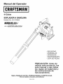
Manual
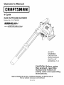
del Operador
4-Ciclos
SOPLADOR A GASOLINA
Modelo No. 316.794830
INCREDI.PULL_
'_
UNBELIEVABLE
with
STARTING
EA S E
MAX FIR_'_INNITIEIN
TM
• SEGURIDAD
• ASSEMBLAJE
• OPERACION
• MANTENIMIENTO
• LISTA DE PIEZAS
PRECAUCION:
Antes de
utilizar este producto,
lea
este manual y siga todas
las reglas de seguridad
y
las instrucciones
de
funcionamiento.
Sears, Roebuck
and Co., Hoffman
Visit our website:
Estates, IL 60179, U.S.A.
www.sears.com/craftsman
769-04212A
Lossimbolos
deseguridad
seutilizan
paraIlamar
suatencion
sobreposibles
peligros.
Lossimbolos
deseguridad
ysusexplicaciones
merecen
todasuatencion
ycomprension.
Lossimbolos
deseguridad
noeliminan
ningQn
peligro
porsimismos.
Lasinstrucciones
oadvertencias
que
ofrecen
nosubstituyen
lasmedidas
adecuadas
deprevencion
deaccidentes.
PARAC HISPAS
NOTA: Para los usuarios en tierras forestales de los EE.UU. y en los
estados de California, Maine, Oregon y Washington. Todos losterrenos
forestales de los EE.UU. y el estado de California (Codigos de Recursos
PQblicos 4442 y 4443), Oregon y Washington, requieren por decreto, que
ciertos motores de combustion interna que se hagan funcionar en zonas
boscosas y/o zonas cubiertas por pastizales, esten equipados con un
parachispas, que sean mantenidos en buen estado de funcionamiento o
que el motor sea construido, este equipado y sea mantenido para evitar
incendios. Consulte los reglamentos pertinentes a esos requisitos con las
autoridades estatales o locales. El incumplimiento de esos requisitos puede
responsabilizarle o someterle a la imposicion de una multa. Esta unidad
fue equipada en la fabrica con un parachispas. Si requiere sustitucion,
hay una silenciador disponible, Pieza # 753-05900 al contactar elSears
o a otro proveedor de servicio calificado.
PROPOSICION 65 DE CALIFORNIA
SIMBOLO
J_
L
_!
J_
L
L
_!
J
4_!_
SIGNIFICADO
ALERTA
DE SEGURIDAD
: Indica peligro,
evitar sufrir graves
advertencia
o precaucion.
lesiones Debe
personales.
prestar Puede
atencionserpara
utilizado junto con otros simbolos o figuras.
PELIGRO
: El no obedecer una advertencia de
sufran graves
seguridad
puede
lesiones.
conducir
Sigaa siempre
que ustedlasu precauciones
otras personasde
seguridad para reducir el riesgo de incendio, descarga
electrica y lesiones personales.
ADVERTENCIA
: El no seguir una advertencia de
sufran lesiones.
seguridad
puede Siga
conducir
siempre
a que
las usted
precauciones
u otras personas
de
seguridad para reducir el riesgo de incendio, descarga
electrica y lesiones personales.
PRECAUCION
: El no seguir una advertencia de
seguridad puede conducir a da_o patrimonial o a que usted
u otras personas sufran lesiones personales. Siga siempre
las precauciones de seguridad para reducir el riesgo de
incendio, descarga electrica y lesiones personales.
LAS EMISIONES DEL MOTOR DE ESTE PRODUCTO
CONTIENEN SUBSTANCIAS QUIMICAS QUE EL ESTADO DE
CALIFORNIA CONOCE COMO CAUSANTES DECANCER,
DEFECTOS DE NACIMIENTO U OTROS DANOS
REPRODUCTIVOS.
REMARQUE: Le ofrece informacion o instrucciones que son
esenciales para la operacion o mantenimiento del equipo.
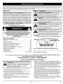
INDICE DE CONTENIDOS
Normas para una operacion segura .......................
E2
Garantia ............................................
E4
Conozca su unidad ....................................
E5
Instrucciones de ensamble ..............................
E6
Informacion del aceite y del combustible ...................
E8
Instrucciones de arranque y apagado .....................
E9
Instrucciones de operacion ............................
El0
Instrucciones de mantenimiento y reparacion ..............
E12
Limpieza y almacenamiento
............................
E15
Resolucion de problemas ..............................
E16
Especificaciones .....................................
E16
Lista de Piezas ......................................
E17
NOmeros de Servicio .........................
Contraportada
N_mero de serie N_mero del modelo N_mero de la
-_
_S/N:
pieza de_bricante
\ MOI:EELM::
I
/
II III
Copie
el ndmero
del modelo/pieza
Copie
el nlJmero
de serie aqui:
del fabricante
aqui:
Lea el manual del operador y siga todas las advertencias e instrucciones de seguridad. De no hacerlo, el operador y/o los
espectadores pueden sufrir graves lesiones.
SI TIENE
PREGUNTAS,
• IMPORTANTE
LLAME
AL
INFORMACION
LEA TODAS LAS INSTRUCCIONES ANTES DE LA OPERACION
1-800-659-5917
DE SEGURIDAD
•
• Inspeccione la unidad antes de usarla. Reemplacelas piezas
da_adas. Verifique si hay fugas de combustible. AsegOrese de que
todos los fijadores esten en su lugar y asegurados. Reemplace las
piezas que esten agrietadas, astilladas o da_adas en cualquier
forma. No opere la unidad con piezas sueltas o da_adas.
• Inspeccione cuidadosamente el Area antes de operar la unidad.
Elimine todos los escombros y los objetos duros o filosos tales
como cristal, alambre, etc.
• No permita ni_os, espectadores ni mascotas en el Area. Los
ni_os, los espectadores y las mascotas deben estar fuera de un
radio de 50 pies (15 m.) como minimo; de todas formas los
espectadores correr_in el riesgo de ser golpeados por objetos
lanzados por la unidad. Se debe exhortar a los espectadores a
que usen proteccion para los ojos. Si se le acerca alguien
apague la unidad de inmediato.
• Oprima el control del estrangulador y compruebe que regresa
automaticamente a la posicion de marcha en vacio. Haga todos
los ajustes o reparaciones antes de usar la unidad.
WARNING:
AI utilizar la unidad, debe observar las
reglas de seguridad. Lea estas instrucciones antes de
operar la unidad a fin de garantizar la seguridad del
operador y cualquier transeOnte. Guarde estas
instrucciones para uso posterior.
• Lea las instrucciones cuidadosamente.
Familiaricese con los
controles y el uso adecuado de la unidad.
• No opere esta unidad cuando este cansado, enfermo o bajo la
influencia de alcohol, drogas o medicamentos.
• Los ni_os y los adolescentes menores de 15 a_os de edad no
deben usar la unidad. Los adolescentes pueden hacerlo bajo la
supervision de un adulto.
• Todos los dispositivos de proteccion y los accesorios de
seguridad deben estar instalados adecuadamente antes de
operar la unidad.
E2
E2
ADVERTENCIAS
DESEGURIDAD
PARALOSRECORTADORES•
AGASOLINA
sus gases pueden explotar si se encienden. Tome las
La gasolina es muy inflamable y
siguientes precauciones:
ADVERTENCIA:
I
I
• Guarde el combustible en envases que hayan sido dise_ados y
aprobados para el almacenamiento de dichos materiales.
• Evite crear una fuente de encendido por combustible derramado.
No arranque el motor hasta que se hayan disipado los vapores
del combustible.
• Antes de Ilenar el tanque de combustible, apague siempre el
motor y espere que se enfrie. No retire nunca la tapa del tanque
de combustible ni cargue combustible mientras el motor este
caliente. No opere nunca la unidad sin la tapa del combustible
colocada firmemente en su lugar. Afloje la tapa del combustible
lentamente para disipar la presion del tanque.
• Agregue el combustible en un Area exterior bien ventilada, donde
no haya chispas ni llamas. Quite lentamente la tapa de
combustible solo despues de haber parado el motor. No fume
mientras este Ilenando de combustible o mezclandolo. Limpie
de la unidad inmediatamente cualquier combustible derramado.
Seque siempre la unidad antes de usarla.
• Aleje la unidad a por Io menos 9,1 m (30 pies), del lugar de carga
de combustible antes de arrancar el motor. No fume, mantenga
las chispas y las llamas abiertas lejos del Area mientras carga el
combustible u opera la unidad.
DURANTE LA OPERACION
• No arranque ni opere la unidad en un cuarto o edificio cerrado.
Los gases de escape de mon6xido de carbono pueden ser letales
en un Area cerrada. Opere esta unidad s61o en un Area exterior
bien ventilada.
• Use lentes o gafas de proteccion que cumplan con las normas
ANSI Z87.1-1989, y proteccion para sus oidos/audicion mientras
opere esta unidad. Use siempre una mascara facial o para
protegerse contra el polvo si la operacion levanta polvo.
• Nunca haga funcionar la unidad sin que esta tenga conectado el
equipo apropiado.
• Para reducir el riesgo de perdida auditiva asociada con los niveles
de sonido, use siempre protecci6n para las oidos cuado haga
funcionar esta unidad.
• Use pantalones largos gruesos, botas, guantes y una camisa de
mangas largas. No use ropa, suelta, joyas, pantalones cortos,
sandalias ni ande descalzo. Rec6jase el cabello por encima de la
altura de los hombros.
• Use la unidad _nicamente con la luz del dia o con buena luz
artificial.
• Mantenga las superficies exteriores libres de aceite y combustible.
• Evite arrancar la unidad accidentalmente. Coloquese en posici6n
de inicio siempre que tire de la cuerda de arranque. El operador y
la unidad deben estar en una posicion estable al comenzar. Lea
las Instrucciones de Arranque y Apagado.
• No ponga la unidad sobre ninguna superficie excepto sobre una
superficie que este limpia y que sea solida, cuando el motor este
prendido. Los desechos tales como la grava, arena, polvo,
cesped, etc, pueden ser absorbidos por la toma de aire y ser
lanzados por la avertura de descarga, causandole danos a la
unidad, propiedad o causandole lesiones graves a los
espectadores o al operario.
• Use la herramienta adecuada. Solomente use esta herramienta
para la tarea que ha sido disenada.
• No fuerce la unidad. Hara mejor el trabajo y con menos
probabilidad de lesi6n bajo la tasa de funcionamiento que fue
disenada.
• No intente alcanzar demasiado lejos ni Io use desde superficies
inestables como escaleras, arboles, pendientes pronunciadas,
techos, etc. Mantenga siempre una posici6n y equilibrio adecuados.
• Sostenga siempre la unidad con ambas manos mientras este en
funcionamiento.
Mantenga las manos, la cara y los pies lejos de todas las partes
m6viles. No toque ni intente detener el rotor cuando este girando.
No la haga funcionar sin los protectores puestos en su lugar.
• No ponga ningQn objeto en las aberturas. No la use cuando
cualquier abertura este bloqueada, mantengalas libres de mugre,
desechos o cualquier cosa que pueda reducir el flujo de aire.
• No toque el motor, o el silenciador. Estas partes se calientan
mucho con la operaci6n. Luego de apagar la unidad, permanecen
calientes durante un tiempo breve.
• No opere el motor a una velocidad mayor que la necesaria para
hacer el trabajo. No haga funcionar el motor a alta velocidad
mientras no Io esta usando.
• Apague siempre el motor cuando demore la operaci6n o mientras
camina de un lugar hacia otro.
• Pare el motor para hacerle mantenimiento, reparaciones, para
instalar o quitarle los tubos de soplado. La unidad debe parar y el
rotor no debe estar girando, para evitar contacto con las cuchillas
que giran.
• Si golpea o se enreda con un objeto extrano pare el motor de
inmediato y compruebe si ha habido algQn dano. No haga
funcionar el equipo antes de reparar el dano. No opere la unidad si
tiene piezas flojas o danadas.
• Use s61o piezas y accesorios de repuesto del fabricante del
equipo original para esta unidad. Puede obtenerlos en su
proveedor de servicio autorizado. El uso de piezas y accesorios
que no son equipo original puede causar graves lesiones al
operador o el dano de su unidad, y la cancelaci6n de su garantia.
• Para reducir el riesgo de incendio, cambie los silenciadores y
parachispas defectuosos. Mantenga el motor y el silenciador libre
de pasto, hojas, grasa excesiva o acumulaciones de carbono.
• Nunca apunte la sopladora hacia a la gente, mascotas o ventanas.
Dirija siempre el soplado de desechos lejos de la gente, animales
y ventanas. Tenga mucho cuidado cuando sople desechos cerca
de objetos s61idos como arboles, autom6viles, paredes, etc.
OTRAS ADVERTENCIAS DE SEGURIDAD
• Nunca guarde la unidad con combustible en el tanque dentro de
un edificio en donde los gases puedan alcanzar una llama
expuesta (pilotos, etc) o chispas (interruptores, motores
electricos, etc.)
• Permita que el motor se enfrie antes de guardarla o transportarla.
AsegQrese de sujetar la unidad mientras transportarla.
• Guarde la unidad en un lugar seco, bien sea bajo Ilave o
suficientemente alto para que evite el uso no autorizado o da_os.
Mantengala fuera del alcance de los ni_os.
• Nunca remoje o chorree la unidad con agua o cualquier otro
liquido. Mantenga los manijas secos, limpios y libres de
escombros. Limpiela despu6s de cada uso, vea las Instrucciones
de Limpieza y Almacenamiento.
• Conserve estas instrucciones. Cons_ltelas con frecuencia y
Qselas para instruir a otros usuarios. Si le presta esta unidad a
otras personas, tambien incluya las instrucciones.
NOTA ESPECIAL: La exposicion a las vibraciones mediante el uso
prolongado de herramientas manuales a gasolina puede causar
da_os en los vasos sanguineos o nervios de los dedos, manos y
articulaciones en las personas que presentan una predisposicion a
trastornos circulatorios o inflamaciones anormales. Por otra parte,
el uso prolongado en el clima frio ha sido relacionado con el da_o
de vasos sanguineos en personas sanas. En caso de ocurrir
sintomas como adormecimiento, dolor, perdida de fuerza, cambio
en el color o textura de la piel o perdida de sensacion en los dedos,
manos o articulaciones, abandone el uso de esta herramienta y
obtenga atencion medica. Un sistema antivibratorio no garantiza la
prevencion de estos problemas. Los usuarios que operan
herramientas motrices en forma regular y continua deben controlar
con cuidado su condicion fisica y la condicion de esta herramienta.
CONSERVE
E3
ESTAS INSTRUCCIONES
• SIMBOLOSDESEGURIDAD
E INTERNACIONALES
•
Este manual del operador describe los simbolos y figuras de seguridad e internacionales que pueden aparecer en este producto
del operador para obtener informacion completa acerca de la seguridad, ensamble, operacion y mantenimiento y reparacion.
SIMBOLO
SIGNIFICADO
SIMBOLO
Lea el manual
SIGNIFICADO
• SIMBOLO DE ALERTA DE SEGURIDAD
Indica peligro, advertencia o precauci6n. Puede ser
utilizado junto con otros simbolos o figuras.
• LEA EL MANUAL DEL OPERADOR
ADVERTENCIA:
Lea el manual del operador y
siga todas las advertencias e instrucciones de
seguridad. De no hacerlo, el operador y/o los
espectadores pueden sufrir graves lesiones.
• USE PROTECCION
I• MANTENGA
ALEJADOS
A
ESPECTADORES
LOS
/_'?r;#_._ I ADVERTENCIA:
Mantenga atodos los
espectadores,
en especial a nifios y animales
dom6sticos apor Io menos 50 pies (15m) de! Area de
cortel
OCULAR Y AUDITIVA
ADVERTENCIA:
Los objetos arrojados por la
unidad y el ruido fuerte pueden causar graves
lesiones oculares y p_ rdida auditiva. Utilice
protecci6n ocular que cumpla con las normas ANSI
Z87.1-1989 y protecci6n auditiva cuando opere esta
unidad. Use una careta completa cuando la necesite.
• COMBUSTIBLE SIN PLOMO
Use s empre combust b e mpJo, nuevo y s n p omo.
I_
' SUPERFICIE
DE CALIENTE
ADVERTENCIA:
No toque un silenciador ni
cilindro calientel Puede quemarsei Estas partes
ca!ientan mucho con e! usol Luego de apagarse
permanecen calientes durante un corto tiempo.
il
1
2
3
-,- J'*, I1
I• CONTROL DEL OBTURA DOR
• PosJclon de OBTURACION COMPLETA .........
2: PoslcJon deOBTURACION PARCIAL
3. • Pos c 6n de MARCHA
I
I
I
I
I
Consulte el manual del operador para obtener
"INDICADOR
DEACEITE
informaci6n acerca
del ti po correcto de aceite.
GARANTIA TOTAL DE CRAFTSMAN
Si este producto de Craftsman Professional falla debido a un defecto en el material o en la mano de obra dentro de un periodo de dos afios a partir
de ta fecha de compra, devuelvalo a cualquier tienda o Centro de Servicio de Piezas y Reparaciones Sears u otro estabtecimiento de Craftsman en
los Estados Unidos para que sea reparado sin costo atguno (o ser reemptazado si resulta imposibte repararlo).
Esta garantia se aplica solamente durante 90 dias si este producto en algQn memento se utiliza para fines comerciales o de alquiler.
Esta garantia abarca SOLAMENTE los defectos en el material o en la mano de obra. Sears NO pagar_:
• Los articulos consumibtes que se desgasten debido at uso normal dentro del periodo de garantia, tal como lineas de corte, filtros de aire o bujias.
• Las reparaciones necesarias debidas a accidente o por no operar o no mantener el equipo de acuerdo con todas tas instrucciones provistas.
• Los mantenimientos preventivos o las reparaciones necesarias debido a mezcla incorrecta de combustible, combustible contaminado o viejo.
Esta garantia le concede a usted derechos legales especificos, y usted pudiera tener otros derechos que varian de un estado a otro.
Sears, Roebuck and Co., Hoffman Estates, IL 60179
Convenio de Protecci6n de Reparaci6n
Felicidades por haber realizado una compra inteligente. Su nuevo producto Craftsman® esta disefiado y fabricado para ofrecerle afios de
funcionamiento confiable. Pero come todos los productos, es posible que sea necesario repararlo de vez en cuando. Ahi es cuando tener un
Convenio de Proteccion de Reparacion puede ahorrarle dinero y problemas.
Esto es Io que incluye el Convenio de Proteccion de Reparacion*:
[]
Servicio experto de nuestros 10,000 especialistas profesionales en reparaciones
[]
Servicio ilimitado y sin costo alguno per piezas y mane de obra en todas las reparaciones cubiertas
[]
Reemplazo del producto per un valor de hasta $1500 si el producto cubierto no se puede reparar
[]
Descuento del 10% en el precio regular del servicio, asi come de las piezas instaladas, que el convenio no cubra; igualmente, 10% de
descuento en el precio regular de comprobacion de mantenimiento preventive
[]
Ayuda r_pida por tel6fono - la Ilamamos Solucion Rapida - asistencia tecnica per telefono de un representante de Sears. Piense en
nosotros come si fu6ramos un "manual del usuario que habla".
Una vez que adquiera el Convenio de Proteccion de Reparacion, todo Io que necesita es hacer una simple Ilamada para programar el servicio
de reparacion. Puede Ilamar a cualquier hera del dia o de la noche, o hacer una cita de servicio por Internet.
El Convenio de Proteccion de Reparacion es una compra libre de riesgo. Si usted cancela per cualquier motive durante el periodo de garantia
del producto, proporcionaremos un reembolso complete. O, un reembolso prorrateado en cualquier memento despu6s de que venza el
periodo de garantia del producto, iAdquiera hey mismo su Convenio de Proteccion de Reparaci6n!
Aplican algunas limitaciones y exclusiones. Para obtener precios e informacibn adicional en los Estados Unidos, Ilame al 1-800-827-6655.
* La cobertura en Canada varia en algunos articulos. Para obtener todos los detalles, Ilame a Sears en Canada al 1-800-361-6665.
Servicio de Instalaci6n Sears
Para la instalacion de electrodomesticos,
abridores de puertas de garaje, calentadores de agua, y otros productos
profesionales de Sears, en los Estados Unidos o CanadA, Ilame al 1-800-4-MY-HOME
®.
E4
para el hogar por
APLICAClON
Limpieza
dejardines,
cocheras,
entradas
deautom6viles,
p6rticos,
patios,
alrededor
deparedes,
cercos,
etc.
Manija
\
Gatillo
Control de
encendido y
apagado
Cubierta del
filtro de aire
Cuerda de
arranque
Control de crucero de
velocidad variable
Bujia de
encendido
Tubo del
soplador
Cubierta del
silenciador
Tapa de II_nado
de aceite
Bomba del
Palanca del
obturador
Cebador
Tubo curvado
Boquilla
concentradora
Tapa del
combustible
E5
ENSAMBLE
DELAUNIDAD
Instalacibn
delTubodelaSopladora
3.
_
personales, apague el motor y espere que el propulsor
Para evitar
graveslos
lesiones
seDVERTENCIA:
detenga antes de conectar
o retirar
tubos.
_
personales y el dafio de la unidad, el tubo del soplador
DVERTENCIA
Para evitar
graves
debe
estar instalado :mientras
opere
esta lesiones
unidad.
Gire la boquilla en el sentido de las agujas del reloj sobre el
tubo de la sopladora hasta que quede apretada (Fig. 4).
I
Boquilla (o tubo
1.
Tubo de la
sopladora
I
Alinee el tope en el extremo del tubo de la sopladora con la
ranura de tope en el extremo inferior de la salida de la
sopladora (Fig. 1).
Fig. 4
Cbmo Quitar el Tubo de la Sopladora
Salida de la sopladora
1.
2.
Tubo de la
sopladora
Sujete
Inserte
Gire el
1/4 de
la unidad firmemente.
un destornillador de cabeza plana en la traba del tubo.
destornillador en sentido contrario a las agujas del reloj
vuelta y mantengalo ahi (Fig. 5).
Traba del tubo
--_-_
Ranura
de tope
Tope
Fig. 1
2.
Inserte el tope del tubo de la sopladora en la ranura de tope de
la salida del tubo (Fig. 1).
3.
Gire el tubo de la sopladora en el sentido de las agujas del reloj
dentro de la salida de la sopladora hasta que el tope se trabe
en su lugar (Fig. 2).
T_
_alidade_la
sopladora
Fig. 5
3.
While holding the screwdriver in a counterclockwise
position,
sujete el tubo de la sopladora y girelo en sentido contrario alas
agujas del reloj (Fig. 5).
4. Tire del tubo de la sopladora de la salida de la sopladora.
Cbmo Quitar la Boquilla
Salida de la sopladora
Tubo de la
sopladora
1.
2.
3.
Sujete el tubo de la sopladora firmemente.
Sujete la boquilla y girela en sentido contrario alas agujas del
reloj hasta que la boquilla se destrabe del tubo de la sopladora
(Fig. 6).
Quite la boquilla del tubo de la sopladora.
Fig. 2
Instalacibn de la Boquilla
1. Alinee el tope en el extremo del tubo de la sopladora con la
ranura del tope en el extremo inferior de la salida de la
sopladora (Fig. 3).
2. Inserte el tope del tubo de la sopladora en la ranura de
tope de la boquilla (Fig. 3).
Tubo de la
sopladora
Boquilla (o
tubo
Tope
Ranura
de tope
Fig. 3
E6
Boquilla (o tubo
curvado)
Tubo de la
sopladora
Fig. 6
ADVERTENClA:
EL LLENAR DEMASIADO EL
CARTER PUEDE CAUSAR LESIONES PERSONALES
GRAVES No podemos exagerar la importancia del
control y mantenimiento del nivel correcto de aceite en
el cigQefial. Verifique el aceite antes de cada uso y
cfimbielo cuando sea necesario segQn se indica en la
seccion de Cambio del aceite.
TIPO DE ACEITE RECOMENDADO
El uso de un aceite del tipo y peso correctos en el cigQefial es
extremadamente importante. Verifique el aceite antes de cada uso y
cambie el aceite con frecuencia. Si no usa el aceite correcto, o utiliza
aceite sucio, puede causar el desgaste y falla prematuros del motor.
Use un aceite de buena calidad SAE 30 de API (American Petroleum
Institute) clase de servicio SG, SF, SH.
CARGA DE ACEITE EN EL CARTER DEL CIGUENAL: USO INICIAL
NOTA: Esta unidad se envia sin carga de aceite. A fin de evitar el
dafio de la unidad, cargue aceite en el carter del cigQefial
antes de intentar arrancar la unidad.
Su unidad trae una botella de aceite
SAE 30 SF, SG, SH de 60 ml (2,03
onzas fluidas) (Fig. 7).
NOTA: Guarde la botella para medir la
cantidad correcta de aceite
cuando deba cambiarlo en el
futuro. Lea Cambio de Aceite. B°qUl_llu_lde'
Desenrosque la tapa de la botella
de aceite y retire el sello de papel
Fig. 7
que cubre la apertura. Vuelva a
colocar la tapa. Corte la punta de Tapbn de relleno de aceite
la boquilla del embudo (Fig. 7).
2. Coloque la unidad sobre una
Anillo __-%_!_
I_
superficie plana.
en"O" __/_
I
3. Saque el tapon de aceite/varilla
Orificiod_
h_J
I
de medicion del cigQefial (Fig. 8).
Ilenado de
_!lll
II
4. Vierta todo el contenido de la
aceite
J]JIl II
botella de aceite en el cigQefial
Fig. 8
(Fig. 9).
NOTA: No agregue nunca aceite al
fJ
combustible o al tanque de
combustible.
5. Limpie todo el aceite que pueda
haberse derramado y vuelva a
instalar el tapon del aceite /
varilla de medicion.
Uso de los combustibles de mezcla
Si decide usar un combustible de mezcla o si su uso es inevitable, le
recomendamos que tome las siguientes precauciones:
•
Use siempre una mezcla fresca de combustible segQn Io
indica su manual del operador
•
Use un aditivo de combustible estabilizador de gasolina
•
Drene el tanque y haga funcionar el motor en seco antes de
guardar la unidad
Uso de aditivos en el combustible
El uso de un estabilizador de gasolina impedirfi la corrosion y reducirfi al
minimo la formacion de depositos de resina. El uso de aditivos puede
evitar que se formen depositos dafiinos en el carburador por hasta ocho
(8)meses. Agregue 23 ml (0,8 de onza) de aditivo por galon de
combustible de acuerdo alas instrucciones del envase. No agregue
NUNCA los aditivos directamente al tanque de combustible de la unidad.
CARGA DE COMBUSTIBLE EN LA UNIDAD
ADVERTENCIA:
Cargue el combustible en un Area
exterior limpia y bien ventilada. Limpie de inmediato
todo combustible que se haya derramado. Evite crear
una fuente de encendido con el combustible
derramado. No arranque el motor hasta que se hayan
evaporado los gases del combustible.
ADVERTENClA:
La gasolina es muy inflamable. Los
gases pueden explotar si se encienden. Apague siempre
el motor y espere que se enfrie antes de cargar el tanque
de combustible. No fume mientras Ilena el tanque.
Mantenga las chispas y las llamas lejos del Area.
1.
Verifique el aceite antes de cada uso
y cfimbielo cuando sea necesario
segQn se indica en la seccion de
Cambio del aceite.
TIPO DE COMBUSTIBLE
RECOMENDADO
1.
Saque la tapa de la gasolina (Fig. 10).
lentamente para evitar lesionarse con el rociado del
ADVERTENCIA:
tapa
del combustible
combustible. No opereSaque
nuncala la
unidad
sin la tapa del
combustible firmemente colocada en su lugar.
Tubo de
descarga del
recipiente de
gasolina
J
Fig. 9
El combustible viejo es la causa
principal del mal funcionamiento de la unidad. AsegQrese de usar
combustible nuevo, limpio y sin plomo.
NOTA: Este es un motor de cuatro ciclos. Para evitar dafiar su
unidad, no mezcle el aceite con la gasolina.
Definicibn de los combustibles de mezcla
Los combustibles actuales con frecuencia son una mezcla de gasolina
y uno o mils oxigenantes como el etano, el metanol o el MTBE (eter).
El combustible con mezcla de alcohol absorbe agua. Un porcentaje de
agua tan pequefio como el 1% en el combustible puede hacer que el
combustible y el aceite se separen. Se forman ficidos mientras estfi
guardado. Cuando use combustible con mezcla de alcohol, use
combustible nuevo (almacenado durante menos de 60 dias).
Tanque de
combustible
Tapa del--_,_
combustible
Fig. 10
2.
Coloque el pico del recipiente de gasolina en el orificio de
Ilenado del tanque de gasolina (Fig. 13) y Ilene el tanque.
NOTA: No Ilene el tanque demasiado.
3. Limpie toda la gasolina que pueda haberse derramado.
4. Vuelva a instalar la tapa de la gasolina.
5. Mueva la unidad por Io menos 9,1 m (30 pies) de la fuente y
sitio de carga antes de arrancar el motor.
NOTA: Elimine la gasolina vieja de acuerdo a los reglamentos
federales, estatales y locales.
E7
ADVERTENClA:
Use esta unidad solo en un Area
exterior bien ventilada. Los gases de escape de
monoxido de carbono pueden ser letales en un Area
cerrada.
Arranque/Apagado
ADVERTENClA:
Evite los arranques accidentales.
Coloquese en posicion de inicio cuando tire de la
cuerda de arranque (Fig. 15 o 16). El operador y la
unidad deben estar en una posicion estable al arrancar
la unidad para evitar graves lesiones personales.
INSTRUCCIONES
1.
2.
3.
Bombilla
del cebador
Palanca del
obturador
Y
t
DE ARRANQUE
Verifique el nivel de aceite en el carter del cigQefial. Lea
Inspecci6n del Nivel de Aceite.
Llene el tanque de combustible con gasolina nueva,
limpia y sin plomo.
Oprima completamente el cebador y su61telo 10 veces.
Hflgalo lentamente. Se deberfl ver un poco de
combustible
en el cebador yen las tuberias de
alimentacibn
de combustible
(Fig. 11). Si no puede ver
el combustible en el cebador, oprimalo y su61telo tantas
veces como sea necesario hasta que vea combustible en
el mismo.
4. Coloque la palanca del obturador en Posicibn 3 (Fig. 12).
NOTA: La unidad debe arrancarse en vacio.
No oprima
el gatillo mientras arranca la unidad (Fig. 13).
5. Coloquese en la posicion de arranque (Fig. 13) y tire de la
cuerda de arranque hasta que sienta un poco de
resistencia. Esto es por Io general aproximadamente de 2 a
4 pulgadas. Tire de la cuerda 4 veces con movimientos
suaves y rfipidos.
6. Coloque la palanca del obturador en la Posicion 2 (Fig. 13).
7. Tire de la cuerda de arranque fuertemente de 1 a 4 veces
para arrancar el motor. No tire de la asa durante
comenzar o la unidad no comenzar&
8. Oprima el gatillo despues de que el motor arranque para
calentarlo durante 30 a 60 segundos.
9. Coloque la palanca del obturador en la Posicion 3 (Fig.
13). La unidad estfl lista para usar.
.......................
Sl... el motor no arranca, regrese al paso 3.
Sl... el motor no arranca despu6s de varios intentos, coloque
la palanca del obturador en la Posicion 3 y tire de la
cuerda de arranque fuertemente de 3 a 8 veces. El motor
debe arrancar. Si no Io hace, repita el procedimiento.
ARRANQUE EN CALIENTE: Si la unidad ya estfl caliente;
coloque la palanca del obturador en la Posicion 2,
asegurfindose de NO oprimir el gatillo del regulador, y
siga los pasos del 7 al 9 anteriormente mencionados.
INSTRUCCIONES
Fig. 11
I{I NH
Bombilla del
cebador
Posicibn 3
®
®G
Posicibn 2
Posicibn 1
Fig. 12
Posicibn de
Arranque
DE PARADA
1.
Libere el gatillo. Deje que el motor se enfrie dejflndolo funcionar
en minima.
2.
Oprima y mantenga oprimido el Control de encendido y
apagado en la posicion APAGADO (O) hasta que el motor se
detenga por completo (Fig. 11).
_k Arranque
Cuerda de arranque
Gatillo
Fig. 13
E8
de
/
SOSTENIMIENTO
DE LA SOPLADORA/ASPIRADORA
I
parese siempre en el lado izquierdo de la unidad para
se muestra
Despu6s en
delaarrancar
Figura 20.
la unidad,
IADVERTENCIA:
operarla, tal como
I
Antes de operar esta unidad, parese en la posicion de operacion.
Verifique Io siguiente:
• El operador esta vestido con la ropa apropiada tal como botas,
gafas de protecci6n, protecci6n auditiva, guantes, pantalones
largos y camisa de manga larga.
• Si las condiciones son polvorientas, el operador Ileva puesta una
mascara.
ADVERTENCIA:
Para evitar lesiones personales
graves, pongase gafas de seguridad en todo momento
cuando maneje esta unidad. Pongase una mascara o
mascara para polvo en sitios que sean polvorientos.
• La unidad se encuentra en buen estado de funcionamiento.
• Los tubos estan puestos y asegurados en su lugar.
CONSEJOS 0TILES SOBRE LA OPERACION
ADVERTENCIA:
Para evitar lesiones personales
graves o dafio a la unidad, asegOrese de que los tubos
de la sopladora esten colocados antes de hacer
funcionar la unidad.
Cbmo usar el control de crucero de velocidad variable
1. Una vez que el motor haya arrancado y este caliente, oprima el
gatillo para acelerar la unidad segOn sea necesario (Fig. 14).
2. Para periodos de funcionamiento mas prolongados y para
eliminar la posibilidad de fatiga en el dedo, mueva el control de
crucero de velocidad variable hacia la posicion RAPIDO para
aumentar poco a poco o mantener la velocidad del motor de la
unidad (Fig. 14). Cuando se oprima el control de crucero de
velocidad variable, el gatillo retrocedera hacia la manija.
3. Para disminuir la velocidad del motor, mueva el control de
crucero de velocidad variable hacia la posicion LENTO y el
gatillo regresara a la posicion de marcha en vacio (Fig. 14).
Control de
crucero
Otras Recomendaciones
• AsegOrese que la unidad no apunte hacia desechos sueltos o
personas antes de ponerla en marcha.
• Compruebe que la unidad se encuentre en buen estado de
funcionamiento. Verifique que los tubos esten puestos y
asegurados en su lugar.
• Sujete siempre la unidad firmemente cuando este funcionando.
Sujete firmemente la manija.
• Se requiere el uso de protecci6n auditiva para reducir el riesgo de
perdida auditiva asociada con los niveles de sonido.
• Opere el equipo solamente durante horas razonables -- no muy
temprano en las mafianas ni muy tarde en las noches, cuando la
gente se pueda molestar. Acate las horas detalladas en las
ordenanzas locales. La recomendaci6n usual es de 9:00 am a 5:00
pm, de lunes a sabado.
• Limite el nOmero de equipos que se usen simultaneamente, para
reducir los niveles de ruido.
• Opere las sopladoras motorizadas a la menor velocidad posible,
para hacer el trabajo y reducir los niveles de ruido.
• Verifique el estado del equipo antes del funcionamiento,
especialmente el tubo de escape, tomas de aire y filtros de aire.
• Use rastrillos y escobas para esparcir los desechos antes de
soplarlos.
• Remoje ligeramente las superficies o use un aditamento para rociar
cuando haya agua disponible y se encuentre bajo condiciones
polvorientas.
• Conserve agua mediante el uso de sopladoras motorizadas en vez
de usar mangueras para muchas de las aplicaciones de prados y
ajardinado, incluyendo areas tales como canales, mallas, patios,
parrillas, p6rticos y jardines.
• Tenga cuidado con los nifios, animales domesticos, ventanas
abiertas y autom6viles recien lavados, y sople los desechos en
forma segura.
• Use la extensi6n completa de la boquilla sopladora de manera que
el chorro de aire salga cerca al suelo.
• Limpie despues de usar las sopladoras y otros equipos. Deposite
los desechos en recipientes para la basura.
• Use la sopladora para arboles, arbustos, macizos de flores y zonas
de limpieza dificil. Use la unidad alrededor de edificios y para
otras limpiezas normales.
• Sujete la sopladora con la mano derecha. Cuando la unidad este
funcionando, no se pare en el lado derecho de la sopladora (Fig.
14). Si Io hace, bloqueara la entrada de aire y ello afectara el
funcionamiento de la unidad. Parese, por el contrario, sobre el
lado izquierdo de la unidad para aumentar al maximo la eficiencia
de la unidad (Fig. 15).
POSICION
INCORRECTA
POSICION
(Posicibn de
marcha en vacio)
Fig. 14
Fig. 15
E9
CORRECTA
PROGRAMA
DE MANTENIMIENTO
seguro sobre estos procedimientos, Ileve la unidad a un
Sears o a otro proveedor de servicio calificado.
NOTA" Los trabajos de mantenimiento, reemplazo o reparacion del
sistema y los dispositivos de control de emisiones pueden ser
realizados por un Sears u otro proveedor de servicio calificado.
Para asegurar funcionamiento maximo de su motor, la inspeccion del
puerto del extractor del motor puede ser necesaria despu6s de 50
horas de la operacion. Si usted nota la RPM perdida, degradacion de
las prestaciones o carencia general de la aceleracion, este servicio
puede ser requerido. Si usted se siente su motor esta en necesidad de
esta inspeccion, refiera el servicio a a se chamusca o el otro distribuidor
cualificado del servicio para la reparacion. No procure realizar este
proceso usted mismo como el da_os de motor pueden resultar de los
contaminantes implicados en el proceso de la limpieza para el puerto.
ADVERTENCIA:
Para evitar lesiones personales
graves, nunca realice mantenimiento ni reparaciones
con la unidad funcionando. Realice siempre el
mantenimiento y las reparaciones con la unidad fria.
Desconecte el cable de la bujia de encendido para
cerciorarse de que la unidad no arrancar&
Estos procedimientos requeridos para el mantenimiento deben ser
realizados con la frecuencia indicada en la tabla. Deben ser incluidos
como parte de toda puesta a punto de cada temporada.
NOTA" Es posible que algunos procedimientos de mantenimiento
requieran herramientas o habilidades especiales. Si no esta
FRECUENCIA
MANTENIMIENTO
Antes de arrancar el motor
Llene el tanque de combustible
Inspeccione el aceite
Cada 10 horas
Limpie y vuelva a aceitar el filtro de aire
p. E11
Primer cambio alas 10 horas
Cada 25 horass en Io sucesivo
Cada 25 horas
Cambie el aceite
Cambie el aceite
Limpie el amortiguador
p. E10
p. El0
p. E13 & E10
10 horas en un motor nuevo
Cada 25 horas
Cada 25 horas
Verifique la separacion entre el brazo oscilante y la valvula y ajuste
Verifique la separacion entre el brazo oscilante y la valvula y ajuste
Verifique la condicion y separacion de la bujia de encendido
200 horas
Lleve la unidad a un Sears o a otro proveedor de servicio calificado para servicio
INSPECCION
REQUERIDO
CONSULTE
nuevo
p. E7
p. El0
de chispas y cambie el aceite
DEL NIVEL DE ACEITE
p. E12
p. E12
p. E13
caliente. El aceite fluira con libertad y Tapbn de relleno de aceite
Ilevara mas impurezas.
__._
1. Retire el tapon de relleno de
Anillo _---_1_
aceite / varilla de medicion,
en "O" _I"_-=_/_ _ I
2. Vierta el aceite fuera del orificio de
Ilenadodeaceiteenunrecipiente
Orificiode_
h_I !
inclinando la unidad hasta una
Ilenado de
L'_--(_tIII
I
posicion vertical (Fig. 19). Deje
aceite
_/P_Jlll I
suficiente tiempo como para
Fig. 18
completar el drenaje.
3. Seque todo el aceite residual
de la unidad y limpie todo el
aceite que pueda haberse
derramado. Elimine todo el
aceite de acuerdo con las
normas federales, estatales y
locales.
4. Vuelva a cargar el carter del
cigQe_al con 60 ml
(2,03 onzas fluidas) de aceite
SAE 30 SF, SG, SH.
NOTA: Use la botella y la boquilla
que guardo del uso inicial
para medir la cantidad
correcta. El nivel de 60 ml
(2,03 onzas) esta
Fig. 19
ADVERTENCIA:
Use guantes para
evitar sufrir lesiones
cuando maneje la
unidad.
con combustible
\
No podemos exagerar la
importancia de verificar y mantener
el nivel correcto de aceite en el
carter del cigQe_al. Inspeccione el 1
nivel de aceite antes de cada uso:
J
1. Detenga el motor y permita que
"L
el aceite drene en el carter del
cigQe_al.
2. Coloque el motor en una
superficie a nivel (Fig. 16).
Fig. 16
3. Limpie el Area alrededor del la
varilla para medir el aceite antes de
Orificio de
sacarla. Mantenga el motor libre de
Ilenado de
tierra, hierbas y demas escombros.
Rosca mas
aceite
4. Saque el tapon de aceite del
interna
cigQe_al.
5. La mirada en el petroleo Ilena hoyo,
utiliza una linterna si necesitado. El
petroleo debe estar tocando apenas
las interiores la mayoria de los hilos
(Fig. 17).
6. Si el nivel de aceite no esta tocando-Fig. 17
la rosca mas interior del agujero de Ilenar aceite, a_ada una
peque_a cantidad al agujero de Ilenar aceite y vuelva a
comprobar (Fig. 17). Repita este procedimiento hasta que el
nivel de aceite alcance la rosca mAs interna del agujero de
Ilenar aceite.
NOTA: No Ilene demasiado la unidad.
NOTA: Verifique que el anillo en O este en su lugar en el tapon de
relleno de aceite / varilla de medicion cuando mida y
cambie el aceite (Fig. 18).
CAMBIO DEL AOEITE
En un motor nuevo, cambie el aceite despu6s de las 10 primeras
horas de operacion. Cambie el aceite mientras el motor aOn esta
L
Nivel de
Ilenado
I 4-Cyde
Fig. 26
EIO
Motor
Oil
Linea de
Ilenado
aproximadamente en la parte superior de la etiqueta de la
botella (Fig. 20). Mida el nivel con la varilla de medicion. Si el
nivel estfi bajo, agregue una pequefia cantidad de aceite y
vuelva a medir (Fig. 17). No Io Ilene demasiado.
5. Vuelva a colocar el tapon de relleno de aceite/varilla de medicion.
6. Vuelva a conectar el manguito de la bujia de encendido.
MANTENIMIENTO
DEL FILTRO DE AIRE
ADVERTENClA"
Para evitar graves lesiones
personales, apague siempre su unidad y espere que se
enfrie antes de limpiarlo o realizar todo tipo de
mantenimiento.
Fig. 24
Fig. 23
Limpieza del filtro de aire
Limpie y vuelva a aceitar el filtro de aire cada 10 horas de operacion. Es
una de las partes cuyo mantenimiento es importante. No mantener
debidamente su filtro de aire puede resultar en funcionamiento
inadecuado o puede causar dafio permanente a su motor.
1. Abra la tapa del filtro de aire. Empuje hacia adentro la lengQeta
que estfi en lado izquierda de la tapa. Despu6s hale hacia
derecho del filtro de aire (Fig. 21).
7.
Instale de nuevo la tapa del filtro de aire. Haga coincidir las ranuras
que hay en la lado derecho de la tapa del filtro de aire con las
lengQetas de la lado derecho de la placa posterior (Fig. 25).
Apoye plato
Ranuras
Orejeta
R
apoye plato
Fig. 25
8.
Filtro de aire
Cubierta del
filtro de aire
Gire la tapa hacia izquierda hasta que la lengQeta de la placa
posterior del filtro de aire se enganche en la ranura de la
izquierda del filtro de aire (Fig. 26).
Orejeta
Fig. 21
2,
3.
Retire el filtro de aire (Fig. 21).
Lave el filtro con agua y detergente (Fig. 22). Enjuague bien el
filtro y dejelo secar.
Filtro de aire
Cubierta del
filtro de aire
Fig. 26
AJUSTE DEL VELOCIDAD MINIMA
La velocidad minima del motor puede ser ajustada. Puede tener
acceso al tornillo de ajuste de minima a traves de un orificio en la
parte superior de la cubierta del motor (Fig. 33).
NOTA: Los ajustes descuidados pueden dafiar su motor seriamente.
Los ajustes del carburador deben ser realizados por un
Sears o proveedor de servicio calificado.
Inspeccibn del Combustible
En general, el combustible viejo es el motivo principal para que la
unidad no funcione en forma adecuada. Drene y vuelva a Ilenar el
tanque con combustible nuevo, limpio y sin plomo antes de hacer
ningOn ajuste. Consulte la Informaci6n acerca del Aceite y Combustible.
Fig. 22
4.
Aplique suficiente aceite limpio de motor SAE 30 para recubrir
ligeramente el filtro (Fig. 23).
5. Apriete el filtro para esparcir y retirar el exceso de aceite (Fig. 24).
6. Vuelva a colocar el filtro (Fig. 25).
NOTA: Si opera la unidad sin el filtro de aire, su garantia serfi
ANULADA.
Ell
Limpieza del Filtro de Aire
La condici6n del filtro de aire es importante para elfuncionamiento de la
unidad. Unfiltro de aire sucio limitara el flujo de aire y cambiara la mezcla de
airey combustible. Con frecuencia esto se confunde con un carburador fuera
de ajuste. Inspeccione lacondicion del filtro de aire antes de ajustar el tornillo
de velocidad minima. Consulte lasecci6n de Mantenimiento del Fil1_ode Aire.
Ajuste del Tornillo de Velocidad Minima
Cubierta del
silenciador
\
Tornillos del
cubierta del
motor (2)
ADVERTENClA"
Es necesario que esta unidad este
funcionando durante el ajuste de la velocidad de marcha
en vacio. Use ropa de proteccion y observe todas las
instrucciones de seguridad para evitar lesiones
personales graves.
AdemAs, al arrancar la unidad o realizar ajustes, NO la
coloque sobre ninguna superficie, que no este limpia y
dura. Los residuos, como gravilla, arena, polvo, hierba,
etc., podrian ser lanzados por el tubo de la sopladora y
ocasionar da_os a la propiedad o lesiones graves a los
transeOntes o al operador.
Si despu6s de inspeccionar el combustible y limpiar el filtro de aire el
motor aOn no funciona en minima, ajuste el tornillo de velocidad
minima segOn se indica a continuacion.
1. Arranque el motor y dejelo funcionar a una minima alta durante
un minuto para que se caliente.
2. Suelte el gatillo del regulador y deje
_}
Tornillo de
que el motor funcione en minima. Si
lJlltl velocidad
el motor se para, inserte un
_
minima
destornillador Phillips peque_o en el
orificio de la cubierta del motor
(Fig. 27). Gire el tornillo de minima
f
_
hacia adentro, en sentido horario, de
a 1/8 de vuelta por vez (segOn sea
necesario) hasta que el motor
funcione en minima suavemente.
La inspeccion del combustible, la limpieza
del filtro de aire y el ajuste del tornillo de
-Fig. 27 -velocidad minima debe resolver la
mayoria de los problemas del motor. Si esto no sucede, y:
• El motor no funciona en minima
• El motor fluctOa o se ahoga al acelerarlo
• Existe una perdida de fuerza motriz
Ileve el carburador a ajustar a un proveedor de servicio calificado.
HUELGO DEL BRAZO OSCILANTE
Esto requiere el desarmado del motor. Si usted siente que no esta
seguro o que no esta calificado como para realizar esto, Ileve la
unidad a un centro de servicio autorizado.
NOTA" Inspeccione el huelgo de la valvula del brazo oscilante con una
galga despues de las primeras 10 horas de operacion y luego
cada 25 horas de operacion en Io sucesivo.
• El motor debe estar frio cuando verifique o ajuste el huelgo de lavalvula.
• Esta tarea debe ser realizada en interiores, en un Area limpia y
libre de polvo.
1. Quite los dos (2)tornillos de lamanija utilizando un destornillador de
hoja plana, o un destornillador de cabeza Torx del nOmero T-20,
mientras sujeta las tuercas con una Ilave para tuercas de 3/8" (Fig. 28).
2. Saque el perno superior situado cerca de la manija de la cuerda del
arrancador con las herramientas mencionadas en el paso 1 (Fig. 28).
3. Desconecte el cable de la bujia de encendido.
4. Limpie la suciedad de alrededor de la bujia de encendido.
Saque la bujia de encendido de la cabeza del cilindro girando
un casquillo de 16mm (5/8 pulgadas) en sentido antihorario.
5. Limpie la suciedad de alrededor de la cubierta del brazo
oscilante. Saque el tornillo que sostiene la cubierta del brazo
oscilante con un destornillador grande de vastago piano o con
una broca Torx T-25 (Fig. 29). Saque la cubierta y la junta del
brazo oscilante.
6. Gire el volante lentamente para Ilevar el piston a la parte superior de
su recorrido (conocido como punto muerto superior). Verifique que:
• El pist6n se encuentre en la parte superior de su recorrido mientras
mira dentro del orificio de la bujia de encendido (Fig. 30).
• Ambos brazos oscilantes se mueven con libertad, y ambas
valvulas estan cerradas.
De no ser asi, repita este paso.
7. Deslice la galga entre el brazo oscilante y el resorte de retorno de la
E12
del
motor (4)
Tornillos del
cubierta del
silenciador (2)
Fig. 28
valvula. Mida el huelgo entre el
vastago de lavalvula y el brazo
oscilante (Fig. 30 y 31). Realice esto en
las valvulas de entrada y de escape.
Orificio de
del brazo
El huelgo recomendado para las
Ilenado de
oscilante
valvulas de entrada y de escape es
aceite
0,076- 0,152 mm (0,003- 0,006
pulgadas). Use un calibrador regular
de automovil de 0,127 mm (0,005
pulgadas). El calibrador debe
deslizarse entre el balancin y el
vastago de la valvula con una ligera
cantidad de resistencia, sin doblarse
Fig. 29
(Fig. 30 y 31).
ENTRADA
Tuercas de ajuste
Brazos oscilantes
Anillo
de "O"
Galga
Fig. 30
Tuerca de ajuste _.
Balancin
0,076-0,152
(0,003-0,006
mm
Calibrador
Vastago de la valvula
Fig. 31
8.
Si el huelgo no se encuentra dentro de las especificaciones:
a. Gire la tuerca de ajuste con una Ilave de 8 mm (5/16 pulgadas)
o una guia de tuercas (Fig. 31).
• Para incrementar el huelgo, gire la tuerca de ajuste en sentido
antihorario.
• Para reducir el huelgo, gire latuerca de ajuste en sentido horario.
b.Vuelva a inspeccionar ambos huelgos, y ajuste si es necesario.
9. Vuelva a instalar la cubierta del brazo oscilante utilizando una nueva
junta. Ajuste el tornillo a 2,2-3,4 Nom (20-30 pulgadas•libra).
10. Inspeccione la bujia de encendido y vuelva a instalar. Lea
Cambio de la Bujia de encendido.
11. Vuelva a instalar el cable de la bujia.
12. Vuelva a instalar la cubierta del motor. Verifique la alineacion de
la cubierta antes de ajustar los tornillos. Ajuste los tornillos.
CAMBIO DE LA BUJIA DE ENOENDIDO
Silenciador
Pantalla del amortiguador
de chispas
Cubierta del amortiguador
de chispas
T-25 o 3/8-pulg.
- _o.
.
l/4-pulg.
Tornillo
hexagonal
_/hexagonal
i,o c,uc,oo
ec°nch°rr°dearena
nI
raspe ni limpie los electrodos. El motor podria dafiarse si
penetran pequefias particulas en el cilindro.
Use una bujia de encendido 753-05784 o Champion #RDZ4H. La
separacion correcta es de 0,635 mm (0,025 pulgadas). Retire la
bujia luego de cada 40 horas de operacion e inspeccione su estado.
1. Apague el motor y espere que se enfrie.
2. Inserte un destornillador de hoja plana debajo de la cubierta de
la bujia y quitela haciendo palanca (Fig. 32).
Cubierta de
la bujia
Fig. 34
3.
Saque el desviador de los pararrayos de la chispa el
silenciador. Quite la cubierta del amortiguador de chispas.
4.
Saque la pantalla del amortiguador de chispas de la cubierta
del amortiguador de chispas.
5.
Limpie la pantalla del amortiguador de chispas con un cepillo
de alambre, o cambiela.
6. Vuelva a instalar la pantalla del amortiguador de chispas, la
cubierta del amortiguador de chispas y el tornillo.
7. Vuelva a instalar la cubierta del silenciador.
LIMPIEZA
]_
Tournevis
plat
Fig. 32
3.
4.
5.
6.
7.
Si
Tome el alambre de la bujia con firmeza y sAquelo de la bujia
de encendido.
Limpie alrededor de la bujia de encendido. Saque la bujia de
encendido de la cabeza del cilindro girando una Ilave de
casquillo de 16 mm (5/8 de pulgada) en sentido antihorario.
Cambie las bujias que esten rajadas, sucias o deterioradas. Fije
la separacion de aire a 0,635 mm
(0,025 pulgadas) utilizando un
calibrador (Fig. 33).
Instale una bujia de encendido con la
separacion correcta en la cabeza del
cilindro. Ajuste girando la Ilave de
0 635 m
casquillo 16 mm (5/8 de pulgada) en (0:025 pulg)_
sentido horario hasta que este
ajustada sin huelgo.
Vuelva a instalar la cubierta de la bujia.
usa una Ilave de torsion, ajuste a:
110-120 pulg.•libras (12.3-13.5 N•m)
No ajuste demasiado.
MANTENIMIENTO
DEL AMORTIGUADOR
Fig. 33
DE CHISPAS
apague siempre su unidad y espere que se enfrie antes de I
ADVERTENCIA:
Para evitar graves lesiones personales, I
limpiarlo o realizar cualquier tipo de mantenimiento.
]
21
Saque la cubierta del silenciador. Lea Huelgo del brazo oscilante.
Con un 3/8 pulg. Ilave hexagonal o un pedacito Torx T-25 y un
1/4 pulg. Ilave hexagonal, quite los tornillos que unen el
desviador de los pararrayos de la chispa al silenciador (Fig. 34).
I
apague siempre su recortador y espere que se enfrie antes
] ADVERTENClA:
Para evitar graves lesiones personales,
de limpiarlo o realizar cualquier tipo de mantenimiento.
Use un cepillo pequefio para limpiar la parte exterior de la unidad. No
use detergentes fuertes. Los limpiadores domesticos que contienen
aceites aromaticos como pino y lim6n, y con solventes como el
queroseno pueden dafiar el bastidor de plastico y la manija. Seque
toda la humedad con un patio suave.
ALMACENAMIENTO
• No guarde nunca la unidad con combustible en el tanque donde
los vapores puedan Ilegar a una llama o chispa.
• Espere que el motor se enfrie antes de guardar la unidad.
• Guarde la unidad bajo Ilave para prevenir el uso por
personas no autorizadas y su dafio.
• Guarde la unidad en un Area seca y bien ventilada.
• Guarde la unidad fuera del alcance de los nifios.
ALMAOENAMIENTO
POR LARGOS PERIODOS DE TIEMPO
Si debe guardar la unidad durante un largo periodo de tiempo:
1. Drene toda la gasolina del tanque en un recipiente. No use
gasolina que haya estado guardada durante mas de 60 dias.
Elimine la gasolina vieja de acuerdo con las normas federales,
estatales y locales.
2. Arranque el motor y dejelo funcionar hasta que se ahogue. Esto
asegura que toda la gasolina se haya drenado del carburador.
3.
Deje enfriar el motor. Saque la bujia de encendido y coloque 5
gotas de aceite de motor de buena calidad en el cilindro. Tire
de la cuerda de arranque lentamente para distribuir el aceite.
Vuelva a instalar la bujia de encendido.
NOTA: Retire la bujia y escurra todo el aceite del cilindro antes de tratar
de arrancar el soplador despu6s de haberlo tenido guardado.
4.
Cambie el aceite. Lea Cambio del Aceite. Elimine el aceite viejo
de acuerdo con las normas federales, estatales y locales.
5.
Limpie bien la unidad y verifique que no existan partes flojas ni
dafiadas. Repare o cambie las partes dafiadas y ajuste los
tornillos, las tuercas o los pernos que esten flojos. La unidad
esta lista para ser guardada.
TRANSPORTE
• Deje enfriar el motor antes de transportar la unidad.
• Asegure la unidad durante su transporte.
• Drene el tanque de gasolina antes de transportar la unidad.
• Ajuste la tapa de la gasolina antes de transportar la unidad.
E13
CAUSA
El tanque de gasolina esta vacio
La bombilla de cebado no fue oprimida Io suficiente
La gasolina es viejo
La bujia de encendido esta arruinada
Parachispas obstruido
ACClON
LIeneeltanque con gasolinanueva
Oprima labombiIIade cebado total
y lentamentede I0 veces
Drene eltanque de gasolina/ Agregue gasolinanueva
Cambie o limpie la bujia de encendido
Limpie o cambie el parachispas
CAUSA
El filtro de aire esta obstruido
La gasolina es viejo
ACClON
Cambie o limpie el filtro de aire
Drene el tanque de gasolina / Agregue gasolina nueva
CAUSA
La gasolina es viejo
El accesorio de corte esta atascado de hierba
El filtro de aire esta sucio
Parachispas obstruido
Drene eltanque de gasolina/ Agregue gasolinanueva
Pare el motor y limpie el accesorio de corte
Limpie o cambie el filtro de aire
Limpie o cambie el parachispas
CAUSA
La gasolina viejo
Bujia en mal estado
Parachispas obstruido
ACClON
Drenareltanque de gasolinay a_adirgasolinanueva
Reemplazar la bujia
Limpiar o reemplazar el parachispas
NOTA:
ACClON
Para reparaciones mas alia de los peque_os ajustes recien mencionados, comuniquese
Sears mAs cercano (1-800-4-MY-HOME) ® u otra agencia de servicio calificada.
con su centro de Piezas y Reparaciones
de
Tipo de motor ................................................................................................................................................................
Enfriado por aire, 4 ciclos
Desplazamiento .......................................................................................................................................................
25 cc (1.5 pulgadas cQbicas)
R.P.M. de soplador .............................................................................................................................................................................
7.000 r.p.m.
R.P.M. de velocidad minima ..................................................................................................................................................
3.200 - 4.400 r.p.m.
Tipo de encendido ........................................................................................................................................
Electronico - MAX FIRE IGNITION TM
Interruptor de encendido .........................................................................................................................................................
Interruptor oscilante
Huelgo de la valvula .....................................................................................................................................
0,076-0,152 mm (0,003-0,006 pulg)
Separacion de la bujia de encendido ................................................................................................................................
0,635 mm (0,025 pulg)
Lubricacion ......................................................................................................................................................................................
Aceite SAE 30
Capacidad de aceite del carter del cigQe_al ............................................................................................................................
60 ml (2,03 onzas)
Combustible ..........................................................................................................................................................................................
Sin plomo
Carburador ...................................................................................................................................................................
Diafragma, multiposicional
Arranque ........................................................................................................................................................
Incredi-Pull TM bobinado automAtico
Silenciador .................................................................................................................................................................
Amortiguado con proteccion
Regulador ....................................................................................................................................................................
Retorno manual del resorte
Capacidad del tanque de combustible .....................................................................................................................................
414 ml (14 onzas)
Peso de la unidad (Sin combustible) ....................................................................................................................................................
5 kg (11 libras)
* Toda las especificaciones contenidas en este manual se basan en la informacion mas reciente disponible en el momento de impresion del
manual. Nos reservamos el derecho de hacer cambios en cualquier momento sin aviso previo.
DECLARACI(SN
DE GARANTiA DE CONTROL DE EMISIONES EVAPORATIVAS DE LA EPA PARA CALIFORNIA
Los Derechos y Obligaciones de Usted segt_n la Garantia
El Consejo de Recursos del Aire (Air Resources Board) de California, la Agencia de Protecci6n del Medio Ambiente (EPA) y Sears Brands LLC (Sears) tienen el
placer de explicar la garantia del sistema de control de emisiones en su motor "off-road" peque_o modelo del aSo 2008 y posterior. En California y los 49 estados,
los nuevos motores "off-road" peque_os deben ser dise_ados, construidos y equipados para que cumplan con las exigentes normas del Estado contra el "smog".
Sears debe garantizar el sistema de control de emisiones en el motor "off-road" peque_o de usted para los periodos de tiempo que se indican a continuacidn
siempre y cuando no haya habido maltrato, negligencia o mantenimiento inadecuado de su motor "off-road" peque_o. El sistema de usted de control de
emisiones pudiera incluir piezas tales como el carburador o sistema de inyeccidn de combustible, el sistema de encendido y el convertidor catalitico. Tambien
pudiera incluir mangueras, correas, conectores y otros conjuntos relacionados con las emisiones. Cuando exista una condicidn que este dentro de la garantia,
Sears reparar_ su motor "off-road" peque_o sin costo alguno para usted, incluyendo diagndstico, piezas y mano de obra. Los motores "off-road" peque_os del
2007 y posteriores est_n garantizados pot dos a_os. Si alguna pieza de su motor relacionada con emisiones es defectuosa, Sears la reparar_ o la reemplazar&
Responsabilidades
del Propietario segt_n la Garantia
Como propietario del motor "off-road" peque_o, usted es responsable de realizar el mantenimiento requerido que se indica en su manual del operador. Sears recomienda
que usted conserve todos los recibos que cubren el mantenimiento de su motor "off-road" peque_o, pero Sears no puede denegar la garantia solamente porque usted no
E14
tenga los recibos ni porque usted no pueda asegurar que se ha realizado todo el mantenimiento programado.
• Sin embargo, como propietario del motor "off-road" pequefio, usted deber& estar consciente de que Sears pudiera denegarle cobertura de la garantia si su motor
"off-road" pequefio o una pieza del mismo ha presentado fallas debido a maltrato, negligencia, mantenimiento inadecuado o modificaciones no aprobadas.
• Usted es responsable de presentar su motor "off-road" pequefio a un Centro de Servicio Autorizado por Sears tan pronto se detecte el problema. Las
reparaciones en garantia deber&n terminarse en un periodo de tiempo razonable, no mayor de 30 dias.
Si tiene alguna pregunta en relaci6n con sus derechos y responsabilidades de acuerdo con su garantia, deber_ Ilamar al 1-800-4-MY-HOME
®.
Cobertura de la Garantia del Fabricante
• El periodo de garantia comienza en la fecha en que se entrega el motor o el equipo al comprador del minorista.
• El fabricante garantiza al propietario inicial, y a cada comprador subsiguiente, por un periodo de dos afios, que el motor no tiene defectos en los materiales
ni la mano de obra que ocasionen la falla de una pieza garantizada.
• La reparaci6n o el reemplazo de una pieza garantizada se realizar& sin costo alguno para el p(_pietario en un Centro de Servicio Autorizado por Sears. Para
conocer la ubicacidn m_s cercana comuniquese con Sears Ilamando al 1-800-4-MY-HOME
.
• Cualquier pieza garantizada que no este programada para reemplazo, segen Io exige el mantenimiento, o que est6 programada solamente para inspeccidn regular
a los efectos de "Reparar o Reemplazar Segen sea Necesario" est& garantizada por el periodo de garantia. Cualquier pieza garantizada que este programada para
reemplazo segen Io exige el mantenimiento, estar_ garantizada por el periodo de tiempo hasta el primer punto de reemplazo programado para esa pieza.
• No se le cobrar_ al propietario por el trabajo de diagndstico que Ileve a la determinacidn de que una pieza garantizada est_ defectuosa, si el trabajo de diagndstico
se Ileva a cabo en un Centro de Servicio Autorizado por Sears.
• El fabricante es responsable de los dafios a otros componentes del motor causados por la falla de una pieza garantizada que est6 todavia en garantia.
• Las fallas ocasionadas debido a maltrato, negligencia o mantenimiento inadecuado no est&n cubiertas por esta garantia.
• El uso de accesorios o piezas modificadas puede ser motivo para desestimar una reclamacidn de garantia. El fabricante no es responsable de cubrir fallas
de piezas garantizadas causadas por el uso de accesorios o piezas modificadas.
• Para presentar una reclamacidn, vaya a su Centro de Servicio Sears Autorizado m_s cercano. Los servicios o reparacidn por motivo de garantia se
realizar_n en todos los Centros de Servicio Sears Autorizados.
• Cualquier pieza de reemplazo aprobada por el fabricante se puede usar al realizar cualquier mantenimiento o reparacidn de piezas bajo garantia relacionadas con
emisiones y se proporcionar&n sin cargo alguno para el propietario. Cualquier pieza de reemplazo que sea equivalente en rendimiento o durabilidad se puede usar
en mantenimiento o reparacidn sin garantia y no reducir_ las obligaciones de garantia del fabricante.
Lista de Piezas de Emisiones en Garantia
Los siguientes componentes se incluyen en la garantia del motor relacionada con emisiones: filtro de aire, carburador, cebador, tuberias de combustible,
recuperacidn de combustible/filtro
de combustible, mddulo de encendido, bujia y silenciador.
DECLARACION DE GARANTIA DE CONTROL DE EMISIONES EVAPORATIVAS PARA CALIFORNIA
Los Derechos y Obligaciones de Usted segt_n la Garantia
El Consejo de Recursos del Aire (Air Resources Board) de California y Sears Brands LLC (Sears) tienen el placer de explicar la garantia del sistema de control de
emisiones evaporativas en su motor "off-road" pequefio (tipo de equipo) modelo del afio 2008 y posterior. En California, los nuevos equipos que usen motores "offroad" pequefios deben ser disefiados, construidos y equipados para que cumplan con las exigentes normas del Estado contra el "smog". Sears debe garantizar el
sistema de control de emisiones evaporativas en su motor "off-road" Lawn & Garden (para el cesped y el jardin) pequefio para el periodo que se indica a
continuacidn siempre y cuando no haya habido maltrato, negligencia o mantenimiento inadecuado de su equipo. Su sistema de control de emisiones evaporativas
pudiera incluir piezas tales como: carburadores, tanques de combustible, tuberias de combustible, tapas de combustible, v&lvulas, recipientes, filtros, mangueras de
vapor, abrazaderas, conectores y otros componentes relacionados. En el caso de los motores de 80 cc o menos, solamente el tanque de combustible est& sujeto a
los requisitos de la garantia de control de emisiones evaporativas de esta seccidn. El desplazamiento de su motor "off-road" pequeSo es de menos de 80 cc.
Cobertura de la Garantia del Fabricante
Este sistema de control de emisiones evaporativas est_ garantizado por dos afios. Si cualquier pieza relacionada con las emisiones evaporativas de su equipo
es defectuosa, la pieza ser_ reparada o reemplazada por Sears.
Responsabilidades del Propietario segt_n la Garantia
• Como propietario del motor "off-road" Lawn & Garden peque_o, usted es responsable de realizar el mantenimiento requerido que se indica en su manual
de propietario. Sears recomienda que usted conserve todos los recibos que cubren el mantenimiento de su Motor Lawn & Garden, pero Sears no puede
denegar la garantia solamente porque usted no tenga los recibos.
• Sin embargo, como propietario del motor "off-road" Lawn & Garden pequefio, usted deber& estar consciente de que Sears pudiera denegarle cobertura de
la garantia si su tanque de combustible ha presentado fallas debido a maltrato, negligencia, mantenimiento inadecuado o modificaciones no aprobadas.
• Usted es responsable de presentar su tanque de combustible Lawn & Garden al centro de distribuci6n o al centro de servicio de Sears tan pronto se detecte
el problem& Las reparaciones en garantia deber&n terminarse en un periodo de tiempo razonable®no mayor de 30 dias. Si tiene alguna pregunta en relaci6n
con la cobertura de su garantia, deber_ comunicarse con Sears Ilamando al 1-800-4-MY-HOME
.
Requisitos de la Garantia por Defectos
(a) El periodo de garantia comienza en la fecha en que se entrega el motor o el equipo a un comprador final.
(b) Cobertura General de la Garantia de Emisiones Evaporativas. El tanque de combustible debe estar garantizado al comprador final y a cualquier propietario
posterior en cuanto a que cuando se instal6 el sistema de control de emisiones evaporativas estaba:
(1) Disefiado, construido y equipado de forma tal que cumplia con todas la regulaciones aplicables; y
(2) Sin defectos en los materiales ni la mano de obra que ocasionen la falla de una pieza garantizada durante un periodo de dos afios.
(c) La garantia de las piezas relacionadas con las emisiones evaporativas ser_ interpretada como sigue:
(1) Cualquier pieza garantizada que no est6 programada para reemplazo segQn requiere el mantenimiento en las instrucciones por escrito, debe estar garantizada por el
periodo de garantia definido en la subseccidn (b)(2).Si alguna de esas piezas falla durante el periodo de cobertura de la garantia, debe ser reparada o reemplazada
por Sears. Cualquier pieza reparada o reemplazada bajo la garantia debe estar garantizada por un tiempo no menor que el periodo de garantia restante.
(2) Cualquier pieza garantizada queen las instrucciones por escrito este programada solamente para inspeccidn regular, debe estar garantizada por el periode de garantia
deflnido en la subseccidn (b)(2).Una declaracidn en dichas instrucciones por escdto al efecto de "reparar o reemplazar segQnsea necesario" no reducir& el penbdo de
cobertura de la garantia. Cualquier pieza reparada o reemplazada bajo lagarantia debe estar garantizada por un tiempo no menor que el periodo de garantia restante.
(3) Cualquier pieza garantizada que este programada para reemplazo, segen exige el mantenimiento en las instrucciones por escrito, debe estar garantizada
por el periodo de tiempo anterior al primer punto de reemplazo programado para esa pieza. Si la pieza falla antes del primer reemplazo programado, la
pieza debe ser reparada o reemplaza por Sears. Cualquier pieza reparada o reemplazada bajo la garantia debe estar garantizada por un tiempo no menor
que Io que resta del periodo anterior al primer punto de reemplazo programado para esa pieza.
(4) La reparacidn o el reemplazo de cualquier pieza garantizada bajo las disposiciones de garantia de este articulo se debe realizar sin costo alguno para el
propietario en una estacidn donde se hagan trabajos de garantia.
(5) Independientemente
de las disposiciones de la subseccidn (4) anterior, los servicios o reparaciones en garantia se deben proporcionar en centros de
distribucidn que esten franquiciados para prestar servicios a los motores o equipos en cuestidn.
(6) No se debe cobrar al propietario por el trabajo de diagndstico para determinar que una pieza garantizada est_ realmente defectuosa, siempre y cuando
dicho trabajo de diagndstico se Ileve a cabo en una estacidn donde se hagan trabajos de garantia.
(7) Durante el periodo de garantia del sistema de control de emisiones evaporativas establecido en la subseccidn (b)(2), Sears debe mantener un suministro
de piezas garantizadas suficiente para satisfacer la demanda esperada de dichas piezas.
(8) AI realizar cualquier mantenimiento o reparacidn en garantia se deben usar piezas de reemplazo aprobadas por el fabricante y se deben proporcionar sin
cargo alguno para el propietario. Tal uso no reducir& las obligaciones de garantia del fabricante que emite la garantia.
(9) El uso de cualquier accesorio o pieza modificada ser& motivo para desestimar una reclamacidn de garantia hecha en conformidad con este articulo. El fabricante que
emite la garantia no ser_ responsable, segen este Articulo, de garantizar fallas de piezas garantizadas causadas por el uso de un accesorio o una pieza modificada.
(10) Sears proporcionar_ los documentos que describen los procedimientos o normas de la garantia, en un plazo de cinco dias h_biles desde que los
solicite el Consejo de Recursos del Aire.
Lista de Piezas de Emisiones en Garantia
(1) Tanque de Combustible
Con cada motor o equipo nuevo se proporcionar_n instrucciones por escrito para el manten-imiento y uso del sistema de control de emisiones evaporativas por parte
del propietario.
E15
E16
E17
REPLACEMENT
PARTS - MODEL 316.794830
4-CYCLE GAS BLOWER
Item
1
Part No.
753-05246
Description
Muffler Screws
2
3
4
5
753-05900
753-05244
791-181025
753-05901
Muffler Assembly (includes 1 & 3)
Muffler Gasket
Screw
Rocker Cover
6
7
8
9
10
11
12
13
753-05902
791-181003
753-05903
753-05673
753-05248
753-05904
753-05905
753-05908
O-Ring
Screw
Throttle Cable
Insulator Gasket
Nut
Insulator
Carburetor Gasket
Carburetor
14
15
791-181751
753-05253
Carburetor
Screw
E18
Item
16
17
18
19
20
21
22
23
24
25
26
*
*
Part No.
753-04223
791-181757
753-05687
753-05906
753-05907
753-05400
753-05909
753-05377
753-05910
753-05784
753-05911
753-05966
753-05912
Description
Air Cleaner Assembly
Air Filter
Nut
Flywheel Assembly
Module
Oil Plug
Oil Fill Tube
Screw
O-Ring
Spark Plug
Lead Wire
Valve
Shortblock
O-Ring
*
(includes 17)
Items Not Shown
Assembly (includes 4-7 & 21-25)
REPLACEMENT
Item
1
2
3
4
5
6
7
8
9
10
11
12
13
Part No.
753-05917
753-05918
753-04595
753-05919
753-05920
753-05926
753-05927
753-05928
753-05929
753-05930
791-181003
753-05931
753-05924
Description
Intake Cover
Spring
Screw
Handle Grips
Impeller Housing (includes 4)
Latch Tube
Nut
Washer
Impeller
Throttle Trigger
Screw
Muffler Cover (includes 3)
Inner Trigger Lock
Item
14
15
16
17
18
19
20
21
22
23
24
25
26
27
28
29
30
Part No.
753-05925
791-182405
753-05921
753-05932
753-05289
753-05933
753-05934
753-05935
753-05377
753-05936
753-05937
753-05938
753-05939
753-05942
753-05964
753-05965
753-01202
PARTS - MODEL 316.794830
4-CYCLE GAS BLOWER
Description
Wavey Washer
Switch
Impeller Housing (includes 4)
Outer Trigger Lock
Fuel Cap
Fuel Tank Assembly (includes 18)
Engine Cover Assembly (includes 3, 21 & 22)
Spark Plug Cover
Screw
Upper Tube
Lower Tube
Flare Tube
Latch Spring
Switch Cover
Wire Ground
Strap Ground
Screw
E19
Your Home
For expert troubleshooting
and home solutions
advice:
www.managemyhome.com
For repair - in your home - of all major brand appliances,
lawn and garden equipment, or heating and cooling systems,
no matter who made it, no matter who sold it!
For the replacement parts, accessories and
owner's manuals that you need to do-it-yourself.
For Sears professional installation of home appliances
and items like garage door openers and water heaters.
1-800-4-MY-HOME ®
Call anytime,
(1-800-469-4663)
day or night (U.S.A. and Canada)
www.sears.com
www.sears.ca
Our Home
For repair of carry-in items like vacuums, lawn equipment,
and electronics, call anytime for the location of your nearest
Sears Parts & Repair Service Center
1-800-488-1222
(U.S.A.)
1-800-469-4663
www.sears.com
To purchase a protection
1-800-827-6655
Para pedir servicio
a domicilio,
www.sears.ca
agreement
on a product serviced by Sears:
(U.S.A.)
1-800-361-6665
de reparaci6n
y para ordenar
Au Canada
piezas:
® Registered
Trademark
/
TM
Trademark
(Canada)
pour service en fran(_ais:
1-800-LE-FOYER
1-888-S U -H O CAR ®
(1-888-784-6427)
(Canada)
Mc
(1-800-533-6937)
Se_!tlr_
/
SM
Service
Mark
of Sears
Brands,
LLC
® Marca Registrada / ru Marca de Fabrica / sM Marca de Servicio de Sears Brands, LLC
MCMarque de commerce / MDMarque deposde de Sears Brands, LLC
© Sears
Brands,
LLC