1
1. This unit
GEX-P5750TVP
This product conforms to new cord colors.
Los colores de los cables de este producto se
conforman con un nuevo código de colores.
Æ…b¹b'« „öÝô« Ê«u« l “UN'« «c¼ r−M¹
Printed in Japan
Imprimé au Japon
<CRD3997-B> ES
<KSNNF> <05C00000>
MANUAL D’INSTALLATION
INSTALLATION MANUAL
Clamps
2. Velcro tape (hard)
2. When mounting on a hatchback
window, use clamps where necessary
to assure the cable is not stretched or
does not cause an obstruction when
the hatch is opened or closed.
1. Remove the
protective
paper and stick
on.
3. Velcro tape (soft)
2. Booster amp section
1. Antenna element
1. Clamps
4. Car mat or chassis
2. Holder
Fig. 1
Fig. 2
Fig. 5
Fig. 6
Fig. 9
Fig. 10
± qJA«
≤ qJA«
µ qJA«
∂ qJA«
π qJA«
±∞ qJA«
1. Remote sensor
1. Clamps
1. Remove moisture, dust, dirt
and oil from where you are
going to stick on the seal.
1. Booster amp section
Decide on a suitable location for mounting
before removing the protective paper.
1. Window glass
1. Booster amp section
20 mm
20 mm
20 mm
2. Seal
2. Antenna elements
2. Double-sided
tape
2. Loading coil
3. Holder
4. Antenna top
Fig. 3
Fig. 4
Fig. 7
Fig. 8
Fig. 11
≥ qJA«
¥ qJA«
∑ qJA«
∏ qJA«
±± qJA«
3. Remove the protective
paper and stick on.
Fig. 12
±≤ qJA«
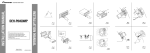
Installation
Note:
• Before making a final installation of the unit, temporarily connect the wiring to confirm that the
connections are correct and the system works
properly.
• Use only the parts included with the unit to ensure
proper installation. The use of unauthorized parts
can cause malfunctions.
• Consult with your nearest dealer if installation
requires the drilling of holes or other modifications of the vehicle.
• Install the unit where it does not get in the driver’s way and cannot injure the passenger if there
is a sudden stop, like an emergency stop.
• When mounting this unit, make sure none of the
leads are trapped between this unit and the surrounding metalwork or fittings.
• Do not mount this unit near the heater outlet,
where it would be affected by heat, or near the
doors, where rainwater might splash onto it.
(Never install in locations such as the above
because of the danger of malfunction due to high
temperatures.)
• Before drilling any mounting holes always check
behind where you want to drill the holes. Do not
drill into the gas line, brake line, electrical wiring
or other important parts.
• If this unit is installed in the passenger compartment, anchor it securely so it does not break free
while the car is moving, and cause injury or an
accident.
• If this unit is installed under a front seat, make
sure it does not obstruct seat movement. Route all
leads and cords carefully around the sliding mechanism so they do not get caught or pinched in the
mechanism and cause a short circuit.
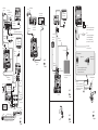
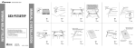
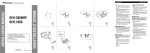
Switching the operation mode
(Fig. 1)
Before installing, use a thin standard
tip screwdriver to switch the operation
mode switch on this unit to the appropriate position for the component you
are using it with.
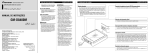
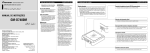
Installing the Unit (Fig. 2)
Adhere the hard Velcro tape (provided)
to the bottom of the hide-away unit
and adhere the soft Velcro tape (provided) to the installation location.
1. This unit
2. Velcro tape (hard)
<ENGLISH>
3. Velcro tape (soft)
4. Car mat or chassis
Note:
• Direct installation on the carpet is possible if the
hard Velcro tape will adhere to the carpet. Do not
use the soft Velcro tape in this case.
• Thoroughly wipe off the surface before affixing
the velcro tape.
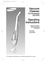
Installing the remote sensor (Fig. 3)
• Do not install on the dashboard where it may be
subjected to direct sunlight. High temperatures
may result in damage to the unit.
• Install within the transmission range of the remote
control signal.
Stick the supplied double-sided tape to
the back of the remote sensor, and
attach it to the center console.
1. Remote sensor
2. Double-sided tape
Installing the Antenna unit
Note:
• Mount the antenna on the inside of the car on
fixed windows such as rear windows or hatchback
windows.
• To assure optimum reception, it is recommended
you mount the TV antenna on a rear (hatchback)
windows pointing down as shown in the Fig. 4,
Fig. 5 and Fig. 6.
• Mounting the antenna near a radio antenna (particularly a booster type) will result in noise. In
this case, consult your dealer concerning mounting location.
• If the antenna is mounted near a radio antenna,
reception quality may be effected during simultaneous reception of TV and radio broadcasts.
• You may not be able to mount the antenna on
windows of certain size, Be sure to select a window that is large enough. (Antenna element
length :40 cm)
• Before mounting the antenna, check the location
of the unit you are going to connect the antenna
to, and make sure it is near enough for the antenna cable to reach. (Antenna cable length: 6 m)
• Never install on top of a glass antenna or heating
wires.
• Secure the antenna firmly, and do not use if it
comes loose. If the antenna falls down, the tips of
the elements may cause injury.
• After installing, make sure children don’t play
with it as it may result in unexpected injury.
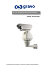
7 Example 1: Mounting on a rear
window (Fig. 4)
1. Clamps
7 Example 2: Mounting on a rear side
window (Fig. 5)
1. Clamps
7 Example 3: Mounting on a hatchback
window (Fig. 6)
1. Clamps
2. When mounting on a hatchback window, use clamps where necessary to
assure the cable is not stretched or does
not cause an obstruction when the hatch
is opened or closed.
Warm the window glass when the
air temperature is low.
To prevent a reduction in adhesive strength ON
the car heater or rear deffoger to warm the glass
to a temperature of 20˚C or more.
Note:
• Do not install with the antenna elements together
as this reduces reception sensitivity.
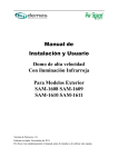
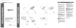
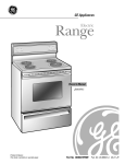
1. Decide on the location for the main
body. (Fig. 7)
When sticking on the main body, make
sure there is a space of 20 mm or more
between the edge of the window and
the antenna elements.
1. Booster amp section
Decide on a suitable location for
mounting before removing the protective paper.
2. Antenna elements
2. Remove dirt and oil from the window with the supplied cleaner.
(Fig. 8)
• Apply the supplied cleaner to a clean cloth
and wipe, applying a little pressure.
• When the cleaner has dried white, wipe off
with a clean, damp cloth.
• Dry thoroughly with another clean cloth.
1. Window glass
3. Mounting on the booster amp
section (Fig. 9)
1. Remove the protective paper and
stick on.
2. Booster amp section
4. Clipping holders onto the antenna
element. (Fig. 10)
When mounting the antenna, clip on
one holder to each element to assure
there’s no space between the glass and
the antenna elements.
1. Antenna element
2. Holder
5. Sticking antenna elements to a
window. (Fig. 11)
Stick on the loading coil first, followed
by the holders and antenna tops in
order. Make sure the antenna is stuck
on straight, with a space of 20 mm or
more between the edge of the window
and the antenna elements.
1. Booster amp section
2. Loading coil
3. Holder
4. Antenna top
6. Sticking the seal on the outside of a
window. (Fig. 12)
Stick on the seal so that it hides the
sticky part of the booster amp section.
1. Remove moisture, dust, durt and oil
from where you are going to stick
the seal.
2. Seal
3. Remove the protective paper and
stick on.
Instalación
Nota:
• Antes de la instalación final de la unidad, conecte
provisionalmente el cableado para confirmar que
las conexiones son correctas y el sistema funciona
satisfactoriamente.
• Utilice solamente las partes incluídas con la
unidad para asegurar una instalación adecuada. El
uso de partes no autorizadas puede ocasionar fallas de funcionamiento.
• Si la instalación requiere del taladrado de orificios
u otras modificaciones del vehículo, consulte con
su agente o concesionario más cercano a su domicilio.
• Instale la unidad en donde no interfiera con el
conductor y no pueda lesionar al pasajero en caso
de una parada repentina, tal como una frenada de
emergencia.
• Cuando monte esta unidad, cerciórese que ninguno
de los cables queda aprisionado entre esta unidad
y accesorios o partes metálicas circundantes.
• No monte esta unidad cerca de la salida del calefactor, en donde podría ser afectado por el calor o
cerca de las puertas, en donde la lluvia podría
salpicar sobre la misma. (Para evitar el riego de
fallos de funcionamiento producidos por las altas
temperaturas, evite la instalación en los lugares
arriba.)
• Antes de taladrar cualquier orificio de montaje
siempre compruebe lo que hay detrás en donde
desea taladrar los orificios. No taladre en la línea
de combustible, cableado eléctrico u otras partes
importantes.
• Si esta unidad es instalada en el compartimiento
de pasajeros, fíjela seguramente de modo que no
se desprenda mientras el automóvil se encuentra
en movimiento, y pueda ocasionar lesiones o accidentes.
• Si esta unidad se instale bajo un asiento delantero,
cerciórese de que no obstruye el movimiento del
asiento. Pase todos los cables y conductores
cuidadosamente a través de los mecanismo
deslizantes, de modo que no queden aprisionados
o atrapados en el mecanismo y ocasionen un corto
circuito.
Conmutación del modo de
operación (Fig. 1)
Antes de la instalación, usando un
destornillador de punta plana, cambie la
posición del interruptor del modo de
operación situado en esta unidad a la adecuada para el componente que usted está
utilizando.
<ESPAÑOL>
Instalación de la unidad (Fig. 2)
Pegue la cinta Velcro (suministrada) sobre
la parte inferior de la unidad oculta-alejada
y pegue la cinta Velcro blanda (suministrada) sobre el sitio de instalación.
1.
2.
3.
4.
Esta unidad
Cinta Velcro (dura)
Cinta Velcro (blanda)
Alfombra del automóvil o chasis
Nota:
• La instalación directa sobre la alfombra es posible
si la cinta Velcro dura puede adherirse a la alfombra. En este caso, no utilice cinta Velcro blanda.
• Limpie completamente la superficie antes de fijar
la cinta adherente o Velcro.
Instalación del sensor remoto
(Fig.3)
• No lo instale en el tablero de instrumentos donde
pueda quedar expuesto a la luz directa del sol. Las
altas temperaturas pueden causar daño a la unidad.
• Instálelo dentro de la gama de transmisión de la
señal.
Adhiera la cinta de doble adherencia al
dorso del sensor remoto, y sujételo a la
consola central.
1. Sensor remoto
2. Cinta de doble adherencia
Instalación de la unidad de antena
Nota:
• Monte la antena en el interior del automóvil sobre
las ventanas fijas tales como ventanas traseras o
ventanas de compuerta trasera.
• Para asegurar una recepción óptima, se recomienda que monte la antena de TV sobre una ventana
trasera (compuerta trasera) apuntando hacia abajo
como se muestra en la Fig. 4, Fig. 5 y Fig. 6.
• Montando la antena cerca de una antena de radio
(particularmente del tipo con refuerzo) resultará
en ruidos. En este caso, consulte su revendedor
con respecto a la ubicación de montaje.
• Si la antena se monta cerca de una antena de
radio, la calidad de la recepción puede ser afectada durante la recepción simultánea de emisoras de
TV y radio.
• Puede no llegar a montar la antena sobre las ventanas de un cierto tamaño. Asegúrese de elegir
una ventana que sea suficientemente grande.
(Longitud de elemento de antena: 40 cm)
• Antes de montar la antena, compruebe la ubicación de la unidad que va a conectar a la antena,
y asegúrese de que se encuentra suficientemente
cerca del cable de antena para que alcance.
(Longitud de cable de antena: 6 m)
• Nunca instale sobre una antena de vidrio o cables
de calentamiento.
• Fije la antena firmemente, y no utilice si se pone
floja. Si la antena cae, las puntas de los elementos
pueden dañarse.
• Después de instalar, asegúrese de que los niños no
jueguen con la antena, ya que esto puede ser peligroso.
7 Ejemplo 1: Montando a una ventana
trasera (Fig. 4)
1. Bridas
7 Ejemplo 2: Montando sobre una ventana de lado trasero (Fig. 5)
1. Bridas
7 Ejemplo 3: Montando a una ventana de
compuerta trasera (Fig. 6)
1. Sección del amplificador de refuerzo
2. Cuando monte sobre una ventana de
compuerta trasera, utilice bridas en
donde sea necesario para asegurar que
el cable no sea estirado, ni ocasione
obstrucciones cuando se abre o cierra la
compuerta.
Caliente el vidrio de la ventana
cuando la temperatura del aire se
encuentre baja.
Para evitar una reducción en la resistencia adhesiva, active el calefactor o el desempañador
trasero del automóvil para calentar el vidrio a
una temperatura de 20°C o más.
Nota:
• No instale con los elementos de la antena juntos
ya que eso reduce la sensibilidad de recepción.
1. Decida sobre la ubicación para el
cuerpo principal. (Fig. 7)
Cuando se fija sobre el cuerpo principal,
asegúrese de que hay un espacio de 20 mm
o más entre el borde de la ventana y los
elementos de la antena.
1. Sección del amplificador de refuerzo
Decida sobre una ubicación adecuada
para el montaje antes de quitar el papel
de protección.
2. Elemento de antena
2. Quite la suciedad y aceite desde la
ventana con el limpiador. (Fig. 8)
• Aplique el limpiador suministrado a un paño
de limpieza y limpie, aplicando poca presión.
• Cuando el limpiador se haya secado en
blanco, limpie quitando con un paño humedecido y limpio.
• Seque completamente con otro paño limpio.
1. Vidrio de ventana
3. Montaje del cuerpo principal. (Fig. 9)
1. Retire el papel protector y pegue.
2. Sección del amplificador de refuerzo
4. Fije los soportes al elemento de
antena. (Fig. 10)
En el montaje de la antena, fije un soporte
a cada elemento para asegurar que no
quede espacio entre la luna y los elementos
de la antena.
1. Elemento de la antena
2. Soporte
5. Fijación de los elementos de la antena a una ventana. (Fig. 11)
Pegue sobre la bobina de carga, seguido
por los soportes y partes superiores de la
antena en orden. Confirme que la antena
esté rectamente pegada, con un espacio de
20 mm o más entre el borde de la ventana
y los elementos de la antena.
1. Sección del amplificador de refuerzo
2. Bobina de carga
3. Soporte
4. Parte superior de la antena
6. Adherencia del sello a la parte
externa de la ventana. (Fig. 12)
Adhiera el sello de manera que oculte la
parte adhesiva de la sección del amplificador de refuerzo.
1. Quite la humedad, polvo, suciedad y
grasa de la parte donde va a pegar el
sello.
2. Sello
3. Quite el papel protector y péguelo.
æWOÐdF«º
VO d²«
WDÝ«uÐ t× « ¨iOÐ√ t½u `³B¹Ë nEM*« nH−¹ UbMŽ •
ÆWKK³Ë WHOE½ ‘UL WFD
ÆÈdš« WHOE½ ‘UL WFD WDÝ«uÐ UU9 tHHł •
…cUM« ÃUł“ .1
Æw Ozd« …—UO « r ł vKŽ VO d²« Æ≥
©π qJA«®
Æt½UJ w tIBË W¹UL(« W—Ë W«“UÐ r .1
e¹eF²« rC r .2
dBMŽ v« UJÝU*« XO³¦ð rJŠ« Æ¥
©±∞ qJA«® Æwz«uN«
dBMŽ q v« UJÝU*« bŠ« XO³¦ð rJŠ« ¨wz«uN« VOdð bMŽ
Æwz«uN« dUMŽË ÃUłe« 5Ð ⁄«d œułË ÂbŽ ÊULC
wz«uN« dBMŽ .1
pÝU*« .2
vKŽ wz«uN« dUMŽ oB« Ƶ
©±± qJA«®Æ…c UM«
UJÝU*UÐ UNF³ð«Ë ¨qOLײ« WHOH vKŽ tIB« W¹«b³« w
wz«uN« ‚UB²« s bQðË ÆVOðd²UÐ wz«uNK ÍuKF« ¡e'«Ë
5Ð U d¦√ Ë√ 3 ≤∞ w«uŠ ⁄«d œułË l ¨WLOI² …—uBÐ
Æwz«uN« dUMŽË …cUM« WUŠ
e¹eF²« rC r .1
qOLײ« WHOH .2
pÝU*« .3
wz«uNK ÍuKF« ¡e'« .4
wł—U)« V½U'« vKŽ …œ«b « oB« Æ∂
©±≤ qJA«® Æ…c UMK
rC r I oö« ¡e'« wDGð YO×Ð WIBK*« vKŽ oB«
Æe¹eF²«
ÊUJ*« sŽ X¹e«Ë ŒUÝËô« ¨—U³G« ¨WÐuÞd« nOEM²Ð r .1
ÆtOKŽ …œ«b « ‚UB« b¹dð
Íc«
…œ«b « .2
Æt½UJ w tIB«Ë W¹UL(« W—Ë W«“UÐ r .3
UbMŽ t«b²Ý« ÂbŽ V−¹ UL ¨ÂUJŠUÐ wz«uN« XO³¦ð V−¹
b dUMF« ·«dÞ« ÊU ¨U{—« wz«uN« jIÝ «–« ÆUOšd `³B¹
ÆÕËd−Ð WÐUô« v« ÍœRð
V³ ²¹ b YOŠ ¨tÐ ‰UHÞô« VF ÂbŽ s bQð ¨VOd²« bFÐ
ÆWFu² dOž WÐU« ÀËbŠ w «c¼
•
•
wHK)« ÃUł“ vKŽ VO d²« ∫± ö¦ 7
©¥ qJA«®
jIK .1
w³½U'« wHK)« ÃUł“ vKŽ VO d²« ∫≤ ö¦ 7
©µ qJA«®
jIK .1
wHK)« »U³« …c U½ vKŽ VO d²« ∫≥ ö¦ 7
©∂ qJA«®
jIK .1
jIK Âb²Ý« ¨wHK)« »U³« …cU½ vKŽ VOd²« bMŽ .2
q³JK WUŽ« Ë√ œ«bA½« ÂbŽ ÊULC Í—Ëd{ u¼ UL³ Š
ÆwHK)« »U³« …cU½ oKž Ë√ `²H t³×Ý
bMŽ
∫WEŠö
∫WEŠö
oBK²Ý XM «–« …œU− « vKŽ dýU³*« VOd²UÐ ÂUOI« pMJ1
Æ…œU− UÐ VKB« wKL<« oö« j¹dA«
ÆwKL<« oö« j¹dA« XO³¦ð q³ UU9 `D « ` «
•
•
bFÐ sŽ rJײ« ”U Š VO dð
©≥ qJA«®
U{dF ÊuJOÝ YOŠ ”UOI« …eNł« WŠu vKŽ t³Odð ÂbŽ V−¹
WFHðd*« …—«d(« Wł—œ sŽ Z²M¹ b YOŠ Æ…dýU³*« fLA« WFýô
Æ“UN'« qDFð
rJײ« …bŠË …—Uý« ‰UÝ—« Èb sL{ tO ÊuJ¹ lu w t³—
ÆbFÐ sŽ
”U Š …dšR vKŽ 5³½U'« s oö« j¹dA« ‚UBUÐ r
Æ”UOI« …eNł« WŠu ed w t²³Ł rŁ ¨bFÐ sŽ rJײ«
bFÐ sŽ rJײ« ”U Š .1
5³½U'« s oô j¹dý .2
•
•
wz«uN« …bŠË VO dð
ÊuJð U bMŽ …c UM« ÃUł“ 5 ²Ð r
ÆWCHM ¡«uN« …—«dŠ Wł—œ
∫WEŠö
…—UO « W¾b ON qOGA²Ð r ¨‚UB²ô« …u ÷UH½« lM*Ë
v« ÃUłe« 5 ² WOHK)« …cUM« sŽ »U³C« q¹e Ë√
Æd¦√ Ë√ W¹u¾ Wł—œ ≤∞ …—«dŠ Wł—œ
∫WEŠö
vKŽ «c¼ qLFOÝ YOŠ U¹uÝ wz«uN« ÍdBMŽ VOdð ÂbŽ V−¹
ƉU³I²Ýô« WOÝU Š ÷UH½«
•
r ł vKŽ oOBK²« lu —d W¹«b³« w Ʊ
©∑ qJA«® Æw Ozd« …—UO «
⁄«d œułË s bQð ¨w Ozd« …—UO « r ł vKŽ ‚UB« bMŽ
Æwz«uN« dUMŽË …cUM« WUŠ 5Ð U d¦√ Ë√ 3 ≤∞ w«uŠ
e¹eF²« rC r .1
ÆW¹UL(« W—Ë W«“« q³ VÝUM*« XO³¦²« lu —d
wz«uN« dBMŽ .2
…c UM« sŽ X¹e«Ë ŒUÝËô« nOEM²Ð r Æ≤
©∏ qJA«® Æo d*« nEM*« WDÝ«uÐ
WHOE½ ‘UL WFD vKŽ tF{uÐ od*« nEM*« Âb²Ý«
ÆtOKŽ öOK jG{« ¨t× «Ë
©rŽU½® oô wKL j¹dý .3
…—UO « qJO¼ Ë√ …œU−Ý .4
•
W²ÐUŁ c«u½ vKŽË …—UO K wKš«b« V½U'« vKŽ wz«uN« V—
ÆwHK)« »U³« …cU½ Ë√ wHK)« ÃUłe« ö¦
vKŽ Êu¹eHK²« wz«u¼ VOd²Ð p×BM½ ¨wU¦ ‰U³I²Ý« ÊULC
qHÝô« v« t−²ð YO×Ð ©wHK)« »U³« …cU½ Ë√® wHK)« ÃUłe«
Æ∂ Ë µ \¥ WO×O{u²« ‰UJýô« w b¼UA¹ UL³ Š
WUš …—uBЮ u¹œ«d« “UNł wz«u¼ s »dIUÐ wz«uN« VOdð
¨WU(« Ác¼ w Æ¡U{u{ tMŽ Z²MOÝ ©“eF vKŽ Íu²;« ŸuM«
ÆVOd²« lu ’uBÐ wK;« pKOË dA²Ý«
dŁQ²ð bI ¨u¹œ«d« “UNł wz«u¼ s »dIUÐ wz«uN« V— «–«
YÐË w½u¹eHK²« ‰UÝ—ö s«e²*« ‰U³I²Ýô« ¡UMŁ√ ‰U³I²Ýô« …œuł
Æu¹œ«d«
ÆWMOF ÂU−Š« «– c«u½ vKŽ wz«uN« VOdð pMJ1 ô b
dBMŽ ‰uÞ® ÆWOU …—uBÐ …dO³ …cU½ —UO²š« s bQð
©rÝ ¥∞ ∫wz«uN«
VOdð b¹dð w²« …bŠu« lu s bQð ¨wz«uN« VOdð q³
q³ UNKB¹ wJ UNÐd W¹UH s bQðË ¨UNOKŽ wz«uN«
©Â∂ ∫wz«uN« q³ ‰uÞ® Æwz«uN«
ÃUłe« vKŽ Vd¹ Íc« ŸuM« s wz«u¼ vKŽ« t³Odð ÂbŽ V−¹
ÆW¾b²« „öÝ« Ë√
•
•
W²R …—uBÐ „öÝô« qË ¨“UN−K wzUN½ VOd²Ð ÂUOI« q³
ÆÂUEM« qOGAð W×Ë öOu²« W× s bQ²K
WOKLFÐ ÂUOI« ÊULC …bŠu« l WId*« ¡«ełô« Âb²Ý« V−¹
V³ ²OÝ …bL²F*« dOž ¡«eł_« «b²Ý« Ê_ ÆW×O× VOdð
ÆqOGA²« w ‰UDŽ« ŸuË w
¡«dł≈ Ë√ »uIŁ Í√ dHŠ dô« VKDð «–«Ë p qOË »d« dA²Ý«
Æ…—UO K ö¹bFð Í√
…œUOI« ¡UMŁ√ ozU « WdŠ tO ÷d²Fð ô ÊUJ w …bŠu« V—
…—UO « nuð WUŠ w ÕËdł ÍQÐ »Ud« WÐU« w V³ ²ð ôË
Æ∆—UÞ d√ ÀËbŠ bMŽ nu²« WUŠ w ö¦ ¨TłUH*«
Ác¼ 5Ð „öÝô« oKFð ÂbŽ s bQð ¨…bŠu« Ác¼ VOdð bMŽ
ÆWDO;« WO½bF*« U³Od²«Ë ¡«ełô«Ë …bŠu«
¨W¾b*« Ãdš Wײ s »dIUÐ …bŠu« Ác¼ VOdð ÂbŽ V−¹
÷dF²ð b YOŠ ¨»«uÐô« s »dIUÐ Ë√ ¨…—«d(UÐ dŁQ²ð b YOŠ
w …bŠu« VOdð ÂbŽ V−¹® ÆUNOKŽ dD*« «dD jU ²
s W&U½ ‰UDŽ« ŸuË dDš V³ Ð ÁöŽ« …—uc*« q¦ sU«
©ÆWOUF« …—«d(« Uł—œ
WOHK)« WIDM*« uKš s bQð ULz«œ »uIŁ Í√ dH×Ð ÂUOI« q³
¨q«dH« VOÐU½√ ¨“UG« VOÐU½« dHŠ ÂbŽ V−¹ ÆdH(« WIDM*
ÆÈdš√ WU¼ ¡«eł√ Í√ Ë√ WOzUÐdNJ« „öÝô«
ÂUJŠUÐ UN²³Ł ¨»Ud« …—uBI w …bŠu« Ác¼ VOdð - «–«
ÀËbŠ w V³ ²ð b U2 ¨…—UO « „d% ¡UMŁ√ XKHð ô YO×Ð
ÆW¹—Ëd Àœ«uŠ Ë√ ÕËdł
ÂbŽ s bQð ¨wUô« bFI*« X% …bŠu« Ác¼ VOdð - «–«
WUð W¹UMFÐ ö³J«Ë „öÝô« q l{ ÆbFI*« Wd( UN²KdŽ
Ë√ U¼—UA×½« ÂbŽË bFI*« ‚ôe½« WO√ sŽ …bOFÐ ÊuJð YO×Ð
—uB ŸuË w V³ ²¹ b U2 Wd(« WO¬ q³ s UNJ ÆWOzUÐdNJ« …dz«bK
•
•
•
•
•
•
•
•
•
•
©± qJA«®qOGA²« l{Ë q¹u%
•
wÝUO oO— ”√dÐ wž«dÐ pH Âb²Ý« ¨“UN'« VOdð q³
v« “UN'« «c¼ vKŽ œułu*« qOGA²« l{Ë ÕU²H q¹uײ
ÆtF Âb² *« “UN−K VÝUM*« l{u*«
•
©≤ qJA«® “UN'« VO dð
•
•
…bŽU v« ©od® VKB« wKL<« oö« j¹dA« oB«
©od® rŽUM« wKL<« oö« j¹dA« oB«Ë WOH<« …bŠu«
Æt³ždð Íc« VOd²« lu v«
“UN'« «c¼ .1
©VK® oô wKL<« j¹dý .2
1. AV-BUS cable
(supplied)
1. Blue
2. AV receiver
(e.g. AVH-P5750DVD)
(sold separately)
3. Yellow
2. AV-BUS input
2. Display
(e.g. AVD-W8000)
(sold separately)
3. Pioneer head unit
(sold separately)
6. Blue
5. Vehicle Dynamics Processor
(e.g. AVG-VDP1)
(sold separately)
4. Black
7. 26-pin cable
(supplied with Vehicle Dynamics Processor)
3. Yellow
3m
5. AV-BUS cable
(supplied)
3m
8. IP-BUS cable
(supplied)
4. AV system display
(e.g. AVX-P7650)
(sold separately)
1. Blue
7. IP-BUS input
2. Fuse holder
1. To video 1 input
6. Black
4. Fuse resistor
9. To video output
3. Remote sensor
(supplied)
12. Display
(e.g. AVD-W8000)
(sold separately)
3. Yellow
3m
1. This unit
4. RCA cable
(sold separately)
6. Yellow
5. To video input
10. RCA cable
(sold
separately)
6. Black
3m
8. Clamp the lead.
7. To rear out
(REAR OUT)
10. Note:
• The position of the parking brake switch depends
on the vehicle model. For details, consult the
vehicle Owner’s Manual or dealer.
±¥ qJA«
9. To front out
(FRONT VIDEO OUT)
4. Black
13. IP-BUS cable
(sold separately)
8. Black
11. Display unit with RCA input jack
(sold separately)
3. Yellow
15. To video 2
input
18. DVD Player
(e.g. XDV-P9—)
(sold separately)
16. White/Red
4. Black
Fig. 15
17. RCA cable
(supplied with
DVD player)
3. Yellow
6. Blue
19. Multi-CD Player
(sold separately)
4. Black
16. White/Red
9. Clamp firmly with
needle-nosed pliers.
Fig. 14
9. IP-BUS cable
(supplied)
14. To video
1 input
.
7. Connection method
3m
11. This unit
6. Blue
5. Red
(Connect this lead only when this unit
is used as STAND ALONE mode.)
To electric terminal controlled by
ignition switch (12 V DC) ON/OFF.
6. Black (ground)
To vehicle (metal) body
8. This unit
4. Black
3. Yellow
To terminal always supplied with power
regardless of ignition switch position.
14. Parking brake switch
11. Light green
Used to detect the ON/OFF status of
the parking brake. This lead must be
connected to the power supply side of
the parking brake switch.
12. Power supply side
13. Ground side
10. This unit
±µ qJA«
10. RCA cable
(sold separately)
1. AV-BUS cable (supplied)
4. Black
50 cm
Fig. 17
4. Black
1. AV-BUS cable (supplied)
3m
Fig. 16
6. Blue
Fig. 13
±∑ qJA«
20. Use AV-BUS cable (50 cm ) if necessary.
«∂ qJA«
±≥ qJA«
Connecting the Units
Note:
3. TV antenna inputs
Connect from 1 in order.
2. TV antenna (supplied)
1. This unit
1. This unit
3. RCA audio output
(White, Red)
6m
5. To audio inputs
2. RCA video output
(Yellow)
4. Fuse holder
4. Fuse holder
7. Display with RCA
input jacks
5. Red
5. Red
4. RCA cables
(sold separately)
6. To electric terminal controlled by
the ignition switch (12 V DC) ON/OFF.
7. Black (ground)
7. Black (ground)
8. To vehicle (metal) body.
Fig. 18
±∏ qJA«
Fig. 19
6. To video input
±π qJA«
• This unit is for vehicles with a 12-volt battery and
negative grounding. Before installing it in a recreational vehicle, truck, or bus, check the battery
voltage.
• To avoid shorts in the electrical system, be sure to
disconnect the ≠ battery cable before beginning
installation.
• Refer to the owner’s manual for details on connecting the other units, then make connections
correctly.
• Secure the wiring with cable clamps or adhesive
tape. To protect the wiring, wrap adhesive tape
around them where they lie against metal parts.
• Route and secure all wiring so it cannot touch any
moving parts, such as the gear shift, handbrake
and seat rails. Do not route wiring in places that
get hot, such as near the heater outlet. If the insulation of the wiring melts or gets torn, there is a
danger of the wiring short-circuiting to the vehicle
body.
• Don’t pass the yellow lead through a hole into the
engine compartment to connect to the battery.
This will damage the lead insulation and cause a
very dangerous short.
• Do not shorten any leads. If you do, the protection
circuit may fail to work when it should.
• Never feed power to other equipment by cutting
the insulation of the power supply lead of the unit
and tapping into the lead. The current capacity of
the lead will be exceeded, causing over heating.
• When replacing fuse, be sure to only use fuse of
the rating prescribed on the fuse holder.
• To prevent incorrect connection, the input side of
the IP-BUS connector is blue, and the output side
is black. Connect the connectors of the same colors correctly.
• To minimize noise locate the TV antenna cable,
radio antenna cable and RCA cable as far away
from each other as possible.
• Cords for this product and those for other
products may be different colors even if they
have the same function. When connecting this
product to another product, refer to the supplied manuals of both products and connect
cords that have the same function.
<ENGLISH>
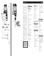
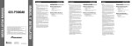
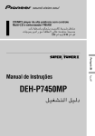
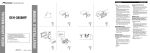
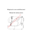
Connection Diagram
7 When using this unit as
“STAND ALONE” mode (Fig. 15)
7 When using this unit as
“SRC : OSD OFF” mode (Fig. 13)
1.
2.
3.
4.
5.
6.
7.
8.
9.
10.
11.
1. AV-BUS cable (supplied)
2. AV receiver (e.g. AVH-P5750DVD)
(sold separately)
3. Yellow
4. Black
5. Vehicle Dynamics Processor (e.g. AVG-VDP1)
(sold separately)
6. Blue
7. 26-pin cable
(supplied with Vehicle Dynamics Processor)
8. IP-BUS cable (supplied)
9. To video output
10. RCA cable (sold separately)
11. This unit
12. Display (e.g. AVD-W8000) (sold separately)
13. IP-BUS cable (sold separately)
14. To video 1 input
15. To video 2 input
16. White/Red
17. RCA cable (supplied with DVD player)
18. DVD player (e.g. XDV-P9—) (sold separately)
19. Multi-CD Player (sold separately)
20. Use AV-BUS cable (50 cm) if necessary.
7 When using this unit as
“SRC : OSD ON” mode (Fig. 14)
1.
2.
3.
4.
5.
6.
7.
8.
9.
Blue
AV-BUS input
Pioneer head unit (sold separately)
AV system display (e.g. AVX-P7650)
(sold separately)
AV-BUS cable (supplied)
Black
IP-BUS input
This unit
IP-BUS cable (supplied)
10.Note
• The position of the parking brake switch
depends on the vehicle model. For details,
consult the vehicle Owner’s Manual or
dealer.
11.Light green
Used to detect the ON/OFF status of the
parking brake. This lead must be connected
to the power supply side of the parking brake
switch.
12.Power supply side
13.Ground side
14.Parking brake switch
To video 1 input
Display (e.g. AVD-W8000) (sold separately)
Remote sensor (supplied)
RCA cable (sold separately)
To video input
Yellow
To rear out (REAR OUT)
Black
To front out (FRONT VIDEO OUT)
This unit
Display unit with RCA input jack
(sold separately)
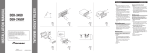
TV antenna connection (Fig. 18)
Disconnecting an AV-BUS connector
(Fig. 16)
7 When connecting the TV Antenna
(supplied)
When disconnecting an AV-BUS connector, grasp it firmly on both sides
and pull towards you. This will unlock
the connector, enabling disconnection.
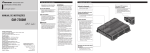
Connecting the power cord (Fig. 17)
1. This unit
2. Fuse holder
3. Yellow
To terminal always supplied with power
regardless of ignition switch position.
4. Fuse resistor
5. Red
(Connect this lead only when this unit is used
as STAND ALONE mode.)
To electric terminal controlled by ignition
switch (12 V DC) ON/OFF.
6. Black (ground)
To vehicle (metal) body.
7. Connection method
8. Clamp the lead.
9. Clamp firmly with needle-nosed pliers.
1. This unit
2. TV antenna (supplied)
3. TV antenna inputs
Connect from 1 in order.
4. Fuse holder
5. Red
6. To electric terminal controlled by ignition
switch (12 V DC) ON/OFF.
7. Black (ground)
8. To vehicle (metal) body.
Rear display connection (Fig. 19)
Note:
• Output to this product’s Rear Display is ON when
the Head Unit’s source is TV. If the Head Unit’s
source is anything other than TV or Head Unit is
OFF, pressing POWER button on the supplied
remote control enables you to operate TV independently for the Rear Display.
• Output from this product’s rear audio output is
monaural.
1. This unit
2. RCA video output (Yellow)
3. RCA audio output (White, Red)
4. RCA cables (sold separately)
5. To audio inputs
6. To video input
7. Display with RCA input jacks
Conexion de las unidades
Nota:
• Esta unidad es para vehículos con una batería de
12 voltios y masa negativa. Antes de montarlo en
un autobús, camión o vehículo de recreación,
compruebe el voltaje de la batería.
• Para evitar cortocircuitos en el sistema eléctrico,
cerciórese de desconectar el cable de batería ≠
antes de comenzar la instalación.
• Para los detalles sobre la conexión a otras
unidades, refiérase al manual del propietario y
luego haga las conexiones correctamente.
• Asegure el cableado con grapas de cable o cinta
aisladora. Para proteger el cableado, envuelva con
cinta aisladora alrededor del cableado en las partes
en donde se apoya contra las partes metálicas.
• Pase y asegure todo el cableado de modo que no
toque ninguna de la partes móviles, tales como
engranaje de cambio, freno de mano y carriles del
asiento. No pase el cableado por lugares que se
calientan, tales como cerca una salida del calefactor.
Si la aislación del cableado se derrite o se rompe,
existe el peligro de que el cableado se ponga en
cortocircuito con la carrocería del vehículo.
• No pase el conductor amarillo a través de un orificio en el compartimiento del motor para conectar
a la batería. Esto dañará el material aislante del
conductor y causará un cortocircuito peligroso.
• No ponga en cortocircuito ninguno de los conductores. Si lo hace, el circuito de protección fallará
en el momento que deba funcionar.
• No alimente otro equipo cortando la aislación del
conductor de suministro de alimentación de la
unidad y enrrollando en el conductor. La capacidad actual del conductor será excedida, ocasionando sobrecalentamiento.
• En el reemplazo del fusible, asegúrese de usar
sólo el fusible del régimen prescrito en el portafusible.
• Para evitar una conexión incorrecta, el lado de
entrada del conector IP-BUS es azul, y el lado de
salida es negro. Conecte los conectores de los
mismos colores correctamente.
• Para minimizar el ruido ubique el cable de la antena de TV, el cable de la antena de radio y cable
RCA tan alejados como sea posible uno de otro.
• Los cables para esta unidad y aquéllas para
las unidades pueden ser de colores diferentes
aun si tienen la misma función. En la conexión de este producto a otro, refiérase a los
manuales suministrados de ambos productos y
conecte los cordones que tienen la misma función.
<ESPAÑOL>
Diagrama de conexión
7 En el uso de esta unidad en el modo
“STAND ALONE” (Fig. 15)
7 En el uso de esta unidad en el modo
“SRC : OSD OFF” (Fig. 13)
1. A la entrada de video 1
2. Visualizador (ej. AVD-W8000) (vendido separadamente)
3. Sensor remoto (suministrado)
4. Cable RCA (vendido separadamente)
5. A la entrada de video
6. Amarillo
7. A la salida trasera (REAR OUT)
8. Negro
9. A la salida frontal (FRONT VIDEO OUT)
10. Esta unidad
11. Unidad visualizadora con conector de entrada
RCA (vendida separadamente)
1. Cable AV-BUS (suministrado)
2. Receptor de AV (ej. AVH-P5750DVD)
(vendido separadamente)
3. Amarillo
4. Negro
5. Procesador de dinámica de vehículo
(ej. AVG-VDP1) (vendido separadamente)
6. Azul
7. Cable de 26 clavijas
(suministrado con el Procesador de dinámica de
vehículo)
8.Cable IP-BUS (suministrado)
9. A la salida de video
10. Cable RCA (vendido separadamente)
11. Esta unidad
12. Visualizador (e.g. AVD-W8000) (vendido separadamente)
13. Cable IP-BUS (vendido separadamente)
14. A la entrada de video 1
15. A la entrada de video 2
16. Blanco/Rojo
17. Cable RCA (suministrado con reproductor de
DVD)
18. Reproductor de DVD (e.g. XDV-P9—) (vendido
separadamente)
19. Reproductor Multi-CD (vendido separadamente)
20. Use el cable AV-BUS (50 cm) si fuera necesario.
7 En el uso de esta unidad en el modo
“SRC: OSD ON” (Fig. 14)
1. Azul
2. Entrada AV-BUS
3. Unidad de cabeza de Pioneer (vendida separadamente)
4. Visualizador del sistema AV (ej. AVX-P7650)
(vendido separadamente)
5. Cable AV-BUS (suministrado)
6. Negro
7. Entrada IP-BUS
8. Esta unidad
9. Cable IP-BUS (suministrado)
Desconexión del conector AV-BUS
(Fig. 16)
Cuando desconecte un conector
AV-BUS, agárrelo firmemente en
ambos los lados y tire. Esto soltará el
conector, permitiendo su desconexión.
Conexión del cable de
alimentación (Fig. 17)
1. Esta unidad
2. Portafusible
3. Amarillo
Al terminal con suministro constante de electricidad, independientemente de la posición
del interruptor de encendido.
4. Resistencia de fusible
5. Rojo
(Conecte este cable sólo cuando se utilice la
unidad en modo STAND ALONE.)
Al terminal de energía eléctrica controlado
por el interruptor de encendido del vehículo
(12 V de CC.) ON/OFF.
6. Negro (masa)
A la carrocería del vehículo (parte metálica).
7. Método de conexión
8. Apriete el cable.
9. Apriete firmemente con alicates de punta de
aguja.
10.Nota:
• La posición del freno de estacionamiento
depende del modelo del vehículo. Para cono-
cer detalles, consulte el manual del propietario del vehículo o a su concesionario.
11.Verde claro
Se utiliza para detectar el estado ON/OFF del
freno de mano. Este cable debe conectarse al
lado de alimentación del interruptor del freno
de mano.
12.Lado de alimentación
13.Lado de masa
14.Interruptor del freno de mano
Conexión a la antena de TV
(Fig. 18)
7 Cuando se conecta la antena de TV
(suministrado)
1. Esta unidad
2. Antena de TV (suministrado)
3. Entradas de antena de TV
Conecte desde 1 en orden.
4. Portafusible
5. Rojo
6. Al terminal de energía eléctrica controlado por
el interruptor de encendido del vehículo (12 V
de CC.) ON/OFF.
7. Negro (masa)
8. A la carrocería del vehículo (parte metálica).
Conexión de presentación visual
trasera (Fig. 19)
Nota:
• La salida a la presentación visual trasera de este
producto está encendida (en ON) cuando la fuente
de la unidad principal está en TV. Si la fuente de
la unidad principal es diferente a TV o la unidad
principal está en OFF, pulse el botón POWER del
mando a distancia proporcionado para poder utilizar la TV independientemente para la presentación visual trasera.
• La salida de audio trasera de este producto es
monofónica.
1. Esta unidad
2. Salida de vídeo RCA (amarilla)
3. Salida de audio RCA (blanca, roja)
4. Cables RCA (vendidos separadamente)
5. A las entradas de audio
6. A las entradas de vídeo
7. Presentación visual con tomas de entrada RCA
æWOÐdF«º
…eNł_« qOuð
WEŠö
q¹œu vKŽ ©W¹ËbO«® ·UI¹ô« q«d ÕU²H lu bL²F¹
Ë√ …—UO « pU qOœ dA²Ý« ¨qOUH²« s b¹e* ¨…—UO «
ÆwK;« pKOË
#U dCš«
OFF qOGAð ·UI¹«ØON qOGAð WUŠ b¹bײ Âb² ¹
V½Uł v« pK « «c¼ qOuð V−¹ Æ©W¹ËbO«® ·UI¹ô« q«d
Æ©W¹ËbO«® ·UI¹ô« q«d ÕU²H* WOzUÐdNJ« …—bIUÐ œËe²«
WOzUÐdNJ« …—bIUÐ œËe²« V½Uł
w{—ô« V½Uł
©W¹ËbO«® ·UI¹ô« q«d ÕU²H
.10
•
.11
.12
.13
.14
©±∏ qJA«® Êu¹eHK²« wz«u¼ qOuð
©o d ® Êu¹eHK²« wz«u¼ qOuð bMŽ 7
“UN'« «c¼
©od® Êu¹eHK²« wz«u¼
ÆVOðd²UÐ ± s qË Êu¹eHK²« wz«u¼ qšœ Uײ
“uOH« pÝU
dLŠ«
qOGAð wF{uÐ tO rJײ« r²¹ Íc« wzUÐdNJ« ·dD« v«
ÕU²H* ©dL² —UOð Xu ±≤ ® OFF qOGAð ·UI¹«Ø ON
ƉUFýô«
©w{—«® œuÝ«
©w½bF*«® …—UO « r ł v«
Æ1
Æ2
Æ3
.4
.5
.6
± u¹bOH« qšœ v«
©WKBHM …—uBÐ ŸU³ð® ©AVD-W8000 q¦® ÷dŽ WýUý
©od® bFÐ sŽ rJײ« ”U Š
©WKBHM …—uBÐ ŸU³¹® RCA q³
u¹bOH« qšœ v«
dH«
(REAR OUT) WOHK)« Ãd)« Wײ v«
œuÝ«
(FRONT VIDEO OUT) WOUô« Ãd)« Wײ v«
“UN'« «c¼
…—uBÐ ŸU³ð® RCA qšœ f³I l ÷dŽ WýUý …bŠË
©WKBHM
.1
.2
.3
.4
.5
.6
.7
.8
.9
.10
.11
©±∂ qJA«® AV-BUS qu qB
5³½U'« ö s ÂUJŠUÐ tJ « ¨AV-BUS qu qB bMŽ
U2 ¨qu*« `² v« ÍœROÝ qLF« «c¼ Æp¼U&UÐ t³×Ý«Ë
ÆtKBHÐ `L OÝ
©±∑ qJA«® …—bI« pKÝ qOuð
.7
.8
©±π qJA«® WOHK)« ÷dF« WýUý qOuð
∫WEŠö
l{Ë vKŽ “UN'« «cN WOHK)« ÷dF« WýUý Ãdš l{Ë ÊuJ¹
vKŽ WO Ozd« …bŠuK —bB*« l{Ë ÊuJ¹ UbMŽ ON qOGA²«
dOž dš« l{Ë vKŽ WO Ozd« …bŠu« —bB ÊU «–« ÆTV l{u«
·UI¹« l{Ë vKŽ WO Ozd« …bŠu« ÊuJð UbMŽ Ë√ TV l{u«
…bŠË vKŽ œułu*« POWER —e« jG{ ÊU ¨OFF qOGA²«
…—uBÐ Êu¹eHK²« qOGA²Ð p `L OÝ WId*« bFÐ sŽ rJײ«
ÆWOHK)« ÷dF« WýUA WKI² “UN'« «cN WOHK)« uB« Ãdš Wײ s uB« Ãdš ÊuJ¹
ÆÍœUŠ«
“UN'« «c¼ Æ1
©dH√® RCA u¹bOH« Ãdš Wײ Æ2
©dLŠ√ ¨iOÐ√® RCA uB« Ãdš Wײ Æ3
©WKBHM …—uBÐ ŸU³ð® RCA ö³ Æ4
uB« qšœ Wײ v« Æ5
u¹bOH« qšœ Wײ v« Æ6
RCA qšœ fÐUI l ÷dFð Æ7
“STAND l{u “UN'« «c¼ «b²Ý« bMŽ 7
©±µ qJA«® ALONE”
•
•
“UN'« «c¼
“uOH« pÝU
dHô«
iGÐ WOzUÐdNJ« …—bIUÐ WLz«œ …—uBÐ œËe¹ Íc« ·dD« v«
ƉUFýô« ÕU²H l{u sŽ dEM«
“uOH« ÂËUI
dLŠ«
l{u« w “UN'« «c¼ «b²Ý« bMŽ jI pK « «c¼ qË®
©ÆSTAND ALONE
qOGAð wF{uÐ tO rJײ« r²¹ Íc« wzUÐdNJ« ·dD« v«
ÕU²H* ©dL² —UOð Xu ±≤ ® OFF qOGAð ·UI¹«Ø ON
ƉUFýô«
©w{—«® œuÝ«
©w½bF*«® …—UO « r ł v«
qOu²« WI¹dÞ
ÆpK « XO³¦ð rJŠ«
ÆÍdЫ ”√— «– W¹œ«—“ WDÝ«uÐ XO³¦²« rJŠ«
.1
.2
.3
.4
.5
VO d²K w×O{u²« rÝd«
“SRC: l{u “UN'« «c¼ «b²Ý« bMŽ 7
©±≥ qJA«® OSD OFF”
©od® AV-BUS q³
ŸU³¹® ©AVH-P5750DVD q¦® u¹bOØ u q³I² ©WKBHM …—uBÐ
dH«
œuÝ«
ŸU³¹® ©AVG-VDP1 q¦® wJOUM¹b« …—UO « oM ©WKBHM …—uBÐ
‚—“«
©wJOUM¹b« …—UO « oM l od® —UL ≤∂ Ë– q³
©od® IP-BUS q³
u¹bOH« Ãdš v«
©WKBHM …—uBÐ ŸU³¹® RCA q³
“UN'« «c¼
©WKBHM …—uBÐ ŸU³ð® ©AVD-W8000 q¦® ÷dŽ WýUý
©WKBHM …—uBÐ ŸU³¹® IP-BUS q³
± u¹bOH« qšœ v«
≤ u¹bOH« qšœ v«
dLŠ«ØiOЫ
©WOLd« u¹bOH« U½«uDÝ« qGA l od® RCA q³
©XDV-P9-II q¦® WOLd« u¹bOH« U½«uDÝ« qGA
©WKBHM …—uBÐ ŸU³¹®
©WKBHM …—uBÐ ŸU³¹® …œbF²*« W−b*« U½«uDÝô« qFA
…—ËdC« bMŽ ©rÝ µ∞® AV-BUS q³ Âb²Ý«
.1
.2
.3
.4
.5
.6
.7
.8
.9
.10
.11
.12
.13
.14
.15
.16
.17
.18
.19
.20
“SRC: l{u “UN'« «c¼ «b²Ý« bMŽ 7
©±¥ qJA«® OSD ON”
‚—“« .1
AV-BUS qšœ
.6
.7
.8
.9
©WKBHM …—uBÐ ŸU³ð® dO½u¹UÐ s WO Ozd« …bŠu«
ŸU³ð® ©AVX-P7650 q¦® u¹bOØ u ÂUE½ ÷dŽ WýUý
©WKBHM …—uBÐ
©od® AV-BUS q³
œuÝ«
IP-BUS qšœ
“UN'« «c¼
©od® IP-BUS q³
.2
.3
.4
.5
.6
.7
.8
.9
∫WEŠö
ju ±≤ W¹—UD³Ð qLFð w²« «—UO K hB “UN'« «c¼
Ë√ ÂUL−²Ýö WBB …—UOÝ w t³Odð q³ VUÝ i¹—QðË
ÆW¹—UD³« bNł s oI% ¨WKUŠ Ë√ WMŠUý
q³ qB s bQð ¨wzUÐdNJ« ÂUEM« w dBI« dz«Ëœ VM−²
ÆVOd²« ¡bÐ q³ ≠ W¹—UD³«
…—bI« rC qË ‰uŠ qOUH²« WdF* pU*« qOœ v≈ lł—≈
Æ`O× qJAÐ öOu²« qLŽ« rŁ Èdš_« …eNł_«Ë
W¹UL( ¨oô j¹dý Ë√ ö³ pÐUA0 qOu²« „öÝ√ X³Ł
UNÝU9 ÊUJ w UNuŠ oö« j¹dA« n ¨qOu²« „öÝ√
ÆWO½bF*« ¡«eł_« l
fLKð Ê√ sJ1 ô UN½√ YO×Ð qOu²« „öÝ√ q X³ŁË —d
W¹ËbO« WKdH«Ë WŽd « dOOGð Ÿ«—– q¦ ¨Wdײ ¡«eł√ W¹√
`³Bð sU√ w qOu²« „öÝ√ —d9 ô ÆbFI*« ‚ôe½« ÊU³CË
„öÝ√ ‰“UŽ dNB½« «–« Æ¡vb*« Ãd »d q¦ ¨…—UŠ
„öÝ_ dB …dz«œ ÀËbŠ dDš „UMN ¨‚e9 Ë√ qOu²«
Æ…—UO « r ł l qOu²«
tKOu² „d;« r v« VI¦« d³Ž dHô« pK « —d9 ô
ÆW¹—UD³UÐ
ÆΫbł …dODš dB …dz«œ V³ ¹Ë pK « ‰eŽ nK²OÝ «c¼
…dz«œ qAHð bI ¨«c¼ XKF «–« ÆpKÝ ÍQÐ dB …dz«œ V³ ð ô
Æp– wG³M¹ ULMOŠ qLF« w W¹UL(«
pKÝ ‰“UŽ lD q³ dš¬ “UNł v« …—bI« W¹cG²Ð «ÎbÐ√ rIð ô
…—bI« “ËU& r²O ÆwŽd pKÝ qËË “UN−K …—bI« b¹Ëeð
Æ«Îbz«“Î ¡ULŠ≈ V³ ¹ U2 ¨pK K WOU(«
…d¹UF Ë– “uO «b²Ý« s bQð ¨ «“uOH« ‰«b³²Ý« bMŽ
Æ «“uOH« pÝU vKŽ W×{u*U
qšb« V½Uł Êu ÊuJ¹ ¨W×O× dOž qOuð WOKLŽ lM*
öu*« qË ÆœuÝ√ Ãd)« V½UłË ¨‚—“√ IP-BUS quLK
ÆW×O× …—uBÐ ÊuK« fH½ qL% w²«
wz«u¼ q³ ¨Êu¹eHK²« wz«u¼ q³ qË ¡U{uC« qOKI²
ÆiF³« UNCFÐ s sJ1 U bFЫ RCA q³Ë u¹œ«d«
…eNłôUÐ WU)« pKðË “UN'« «c¼ „öÝ« Ê«u« ÊuJð b
qOuð bMŽ ÆqLF« fH½ UN ÊU uË v²Š WHK² Èdšô«
«œUý—« U³O² v« lł—≈ ¨dš« “UNł v« “UN'« «c¼
fH½ UN w²« „öÝô« qË rŁ s¹“UN'« öJ qOGA²«
ÆUF nzUþu«
•
•
•
•
•
•
•
•
•
•
•
•