1
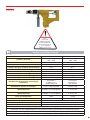
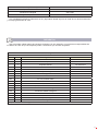
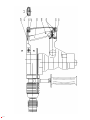
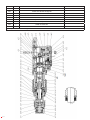
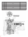
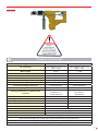
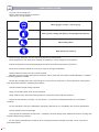
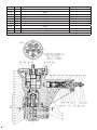
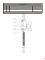
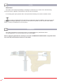
MANUAL DE INSTRUCCIONES
OPERATING INSTRUCTIONS
MARTILLO PERFORADOR NEUMÁTICO
HIDRAULIC HAMMER DRILLS
COD. 79915
ESPAÑOL.........................................1
ENGLISH.......................................19
GARANTIA / GUARANTEE............37
ESPAÑOL
Antes
de usar este
aparato asegúrese
de estar familiarizado
con las instrucciones de
uso y seguridad.
ESPECIFICACIONES TÉCNICAS
Presión de funcionamiento
max. 1137 PSI
max. 80 bar
Conexión de aceite
SAE PORT No. 8 (3/4 x 16
UNF – 2 B)
SAE PORT No. 8 (3/4 x 16
UNF – 2 B)
Potencia del motor
1.6 HP
1.2 kW
Volumen/flujo de aceite
4– 11.9 galones/ min
15- 45 l/min
Conexión del agua mediante válvula de bola
R ¼”
R ¼”
Diámetro interior de la manguera
0.3937 inch
10 mm
Velocidad sin carga
500 +/- 50 rpm
500 +/- 50 1/min
Velocidad con carga
450 +/- 50 rpm
450 +/- 50 1/min
Ritmo de perforación bajo carga
0-3400 golpes/min
0-3400 golpes/min
Rango de perforación en hormigón
0.19685 – 1.102 pulgadas
5-28 mm dia.
Rendimiento de perforación en hormigon
medio-duro
0.4728 dia. =
2.0853 cu. in =
11.82 inches/ min
12 mm dia =
34 cm³/min =
300 mm/min
Rendimiento óptimo en hormigón
0.472 –0.787 pulgadas
12-20 mm dia.
Perforación en acero con portabrocas de
rápida liberación
0.19685 – 0.5118 pulgadas
5-13 mm dia.
Perforación en madera con portabrocas de
rápida liberación
0.19685 – 1.1811 pulgadas
5-30 mm dia.
Peso (sin mangueras)
18 lbs
8.2 kg
Dimensiones
18” L x 10 ¼” H x 4” W
L460 x H260 x B102 mm
Adaptador
SDS Plus
Nivel de sonido
92 dB(A)
Medida de vibración
4.5 m/s²
Embrague de seguridad contra exceso de carga y accidentes
Engranajes con sello ajustado antipolvo con lubricación central y permanente (mantenimiento gratuito)
Mango ajustable lateral con calibre de profundidad y descarga de agua
Kit supletorio: 1 caja para transporte, 1 protección contra polvo
1
INSTRUCCIONES DE SEGURIDAD
Cualquier herramienta eléctrica puede ser peligrosa.
Por favor siga estos simples procedimientos.
Hágalo por su seguridad.
Lleve gafas (para evitar daños por chispas).
Lleve guantes (Podría cortarse con los bordes afilados de las
piezas de trabajo).
Lleve calzado de protección.
Lleve ropa de protección.
Quítese anillos, relojes, corbatas, etc., que pudieran enroscarse en la máquina. Vístase adecuadamente.
No lleve ropa floja, ni joyería, puesto que podrían engancharse en las partes móviles.
Siga los procedimientos generales actualizados y los procedimientos apropiados de seguridad y
prevención de accidentes.
No trabaje nunca bajo los efectos del alcohol, drogas o fuerte medicación.
Asegúrese siempre de tener un punto de apoyo seguro.
Mantenga siempre la posición y equilibrio apropiados. No trabaje nunca con la máquina mientras se
encuentra en una escalera o en un andamio.
Asegure siempre la zona de trabajo. Emplee sargentos o tornillos de banco para fijar las piezas. Esto es
más seguro que emplear las manos. Agarre férreamente la máquina durante la operación.
Mantenga el área de trabajo limpia y despejada.
Mantenga los niños lejos y evite que otras personas entren en contacto con la máquina.
Si la máquina se detiene -por cualquier razón- apáguela, para evitar una situación incontrolable si se pone
en funcionamiento de manera inesperada.
No opere con la máquina si está dañada, ajustada de manera inapropiada o cuando no se ha montado
completamente o se ha hecho de manera incorrecta.
Revise la manguera por si estuviera dañada.
Evite las chispas-creadas por la hoja de sierra- en ambientes peligrosos. Durante el proceso de corte
aplique siempre una cantidad suficiente de agua para enfriar la hoja de sierra y el material cortado.
No emplee máquinas con una fuerza excesiva. Su rendimiento es mejor y más seguro cuando trabaja a la
velocidad prescrita.
2
Revise las partes dañadas.
Antes de usar la máquina, las partes dañadas y los dispositivos de protección deberían ser revisados
cuidadosamente, para asegurarse de que trabajan sólidamente y que cumplen con la función para la que
han sido diseñados. Revise la alineación, las conexiones, y los acoplamientos de las partes móviles. Revise
también si las partes están rotas. Las partes o dispositivos de protección que estén dañados deberían ser
cambiados o reparados por personal cualificado, a no ser que se indicase otra cosa en estas instrucciones
de operación. Se aplica lo mismo a los interruptores y a los gatillos. No debería emplear la máquina, si ésta
no se puede accionar o detener mediante el gatillo.
El uso de otros accesorios, u otros artículos que no se especifican en este libro de instrucciones, podrían
suponer un riesgo para su persona.
Emplee la máquina solo después de estar capacitado para ello o bajo la supervisión de personal
cualificado.
No exceda nunca la presión máxima de operación.
Para adquirir el producto acuda a un proveedor nacional valido.
No opere con la herramienta a temperaturas por encima de 140° F / 60°C.. Operar a altas temperaturas
puede causar mayores daños que operando a temperaturas normales, lo que puede provocar que el operario
este incomodo.
¡ATENCIÓN! No use nunca una manguera flexible como si de un asa se tratase
USO
USO
La máquina está diseñada para perforar sobre hormigón madera. La máquina está dirigida al uso por
personal profesional. Solo personal autorizado y entrenado puede utilizarla, mantenerla y repararla. El
personal debe estar especialmente instruido sobre los riesgos potenciales. El área de uso puede ser:
construcción, fábricas, reformas, montaje y desmontaje.
Manipular o modificar la máquina no está permitido. Observe las instrucciones sobre el uso, cuidado y
mantenimiento en las instrucciones de uso. Los peligros pueden derivarse de la máquina y de los materiales
auxiliares, si no se utilizan o sujetan correctamente.
USO INADECUADO
Cualquier uso ajeno al previsto y descrito se considera un uso inadecuado.
Trabajar sin equipamiento de protección personal.
ZONAS DE PELIGRO
Condiciones
de uso
Función normal
Mal funcionamiento
Uso indebido
Uso esperado
Caída de la máquina
Transporte de
la máquina en
condiciones
operables
Desconocido
La máquina solo funciona con
el interruptor apretado
La máquina funciona
sin apretar el
interruptor
El interruptor
está bloqueado
en la posición de
encendido
Desconocido
La máquina mueve la pieza
La pieza se bloquea
Desconocido
Desconocido
Fase de vida
Transporte
Transporte de la máquina en
condiciones inoperables
Uso
3
Mantenimiento
Montaje de filtro e hidráulica
Avería en la
máquina
Desconocido
Desconocido
REQUERIMIENTOS DEL SISTEMA HIDRÁULICO
Se requiere una presión de 80 bar/ 1137 PSI y un volumen de flujo de 15 l/ min/ 4 gallons/ min para
conseguir el rendimiento específico. Un volumen de flujo mayor de 15 l/ min / 4 gallons/ min se redirige al
tanque vía bypass. A presiones mayores de 80 bar/ 1137 PSI, debe utilizarse la válvula de control de presión.
¡ATENCIÓN!
Nunca use la herramienta hidráulica sin una válvula de refuerzo en línea.
El sistema no debe tener una presión mayor de 250 PSI/ 17 medida al final de las mangueras utilizadas.
Las condiciones del sitema para la medida están al máximo de viscosidad de fluido o 400 ssu / 82
centistokes (temperatura mínima de uso).
El sistema hidráulico debe tener suficiente absorción de calor para limitar la temperatura máxima del
aceite a 140° F / 60° C en la máxima expectativa de temperatura ambiental. La capacidad de refrigeración
mínima recomendada es 5 hp / 3.73 kW a una diferencia de 40° F / 4° C entre el ambiente y la temperatura
del aceite.
El sistema hidráulico debe tener una filtración mínima de 25 micras de circulación constante. Se
recomienda los elementos del filtro sean del tamaño para un flujo de al menos 30 gpm/ 114 lpm para el punto
de inicio de la temperatura fría y la máxima capacidad de suciedad.
EL tamaño de manguera recomendado es de 0.500 inch / 12 mm I.D. a 50 ft / 15 m long y 0.625 inch / 16
mm I.D. aumentar solo a 100 ft / 30 m.
La manguera de retorno del martillo hidráulico rotatorio debe estar conectada directamente al circuito
de regreso e ir directamente a través del filtro de aceite, válvula térmica y el refrigerador de aceite hasta
la reserva. Para evitar atascos o inversión de presiones, el fluido no debe ser conducido en su regreso
mediante una válvula reversible.
El martillo hidráulico rotatorio no puede ser utilizado con el fluido hidráulico invertido. Las mangueras de
suministro (IN) y regreso (OUT) deben estar conectadas como se marca a los lados de las conexiones.
¡IMPORTANTE!
No accione la manguera de retorno a través de una válvula direccional o un bloque de válvulas. Si
el circuito opera desde un bloque de válvulas, coloque una válvula en el puerto de presión. Conecte la
herramienta de retorno directamente a la línea de retorno de flujo.
Su martillo perforador hidráulico es una herramienta de apertura centrada. Opere solo con un circuito
hidráulico cuya apertura este en centro. Opere con circuitos hidráulicos cuyo cierre este en el centro, si opera
con herramientas cuyo cierre este centrado.
El martillo perforador solo puede emplearse con aceite.
Cuando se este suministrando potencia al sistema, preste atención a que el taladro del martillo no opera
con una presión que exceda las características indicadas.
Emplee válvulas reguladoras de presión, en caso contrario la máquina podría dañarse o quedar destruida.
Cuando se esté operando a una temperatura de alrededor de 4º C, se pueden dar interrupciones en el
impacto. Por eso es recomendable encender primero la máquina y dejar que se caliente.
CARACTERÍSTICAS
4
Fluido hidráulico
Aceite hidráulico
Presión de alimentación
80 bar / 1137 PSI
Volumen de fluido
15- 45 l/ min / 4– 11.9 galones
Temperatura del aceite
35°C÷80 °C
Filtro del aceite
grado de pureza ISO 18/13
PROTECCIÓN Y CUIDADO DEL EQUIPO
¡Importante!
Además de las anteriores instrucciones de seguridad, observe las siguientes instrucciones para la
protección y cuidado del equipo.
Almacene siempre la herramienta en un lugar limpio y seco, a salvo de daños o robos.
Mantenga siempre legibles las marcas de las herramientas críticas, como pegatinas o etiquetas.
Las mangueras de suministro deben tener una presión de trabajo de 2500 PSI/ 175 bar.
Utilice siempre mangueras que tengan una superficie interior resistente al aceite y una superficie exterior
resistente a abrasión.
Cerca de conductores eléctricos, utilice mangueras certificadas y etiquetadas como no conductoras.
La reparación de herramientas debe ser llevada a cabo solo por personal experimentado.
Asegúrese de que todos los acopladores se limpian con un trapo antes de conectarlos.
EL suministro de potencia hidráulica debe estar en la posición “OFF” cuando se acople o se separen las
piezas hidráulicas. Si no se hace esto pueden dañarse los acopladores y causar un sobrecalentamiento en el
sistema hidráulico.
No exceda el rango de flujo en 13.2 gpm/ 50 lpm puesto que eso podría producir un fallo inmediato en las
juntas internas de la herramienta.
Asegúrese de que la manguera del circuito de presión (con la desconexión rápida, hembra) está
conectado con la conexión “IN” debajo del lado derecho de la herramienta. La manguera del circuito de
retorno (con la desconexión rápida, macho) se conecta con la conexión “OUT” que se encuentra debajo del
centro de la herramienta.
No invierta el flujo del fluido indicado en las conexiones de la herramienta. El flujo, cuando esta invertido,
no estará limitado por la válvula de control de flujo prioritaria.
Emplee siempre la herramienta de centro abierto (OC) en los circuitos de apertura centrada.
INSTRUCCIONES DE USO
No ejerza demasiada presión a la máquina. Esto no aumentará su rendimiento. Solo posicione la tuerca y
guíela al agujero.
Colocando la máquina en la caja.
Asegúrese de que la cubierta ajustable está bloqueada en el ajuste “martillo hidráulico rotativo”.
Mango lateral
Puede ser girado hasta 360° y bloqueado en cualquier posición deseada.
Calibre de profundidad
Presione el botón de desbloqueo, ajuste la profundidad y suelte el botón.
Lubricación de la fresa frontal
Limpie de vez en cuando la fresa frontal con moderación mediante un espray lubricante.
figura 1
figura 2
figura 3
figura 4
figura 5
5
Perforación en ambientes explosivos
Figura 1: La broca debe enfriarse con agua para evitar chispas. Hacer la conexión de agua mediante una
válvula de bola.
Martillo hidráulico rotatorio
Figura 2: Tire hacia atrás del manguito de ajuste y gire a derechas para bloquearlo. No emplee el portabrocas de cambio rápido en esta posición porque las brocas y las herramientas podrían quedar dañadas.
Figura 3: Tire hacia atrás del manguito de detención e introduzca la broca. Gire el manguito de detención
hasta que haga presión en la posición de salida. Presione el taladro contra la superficie de trabajo antes de
encenderlo, de lo contrario no martilleará correctamente.
Figura 4: Cuando comience a perforar materiales frágiles (baldosas, etc.), desbloquee el manguito de ajuste
a la posición de “martillo cincelador” (“rotary drilling only”), sujete la máquina mediante el manguito de ajuste
y presione lentamente contra la superficie a perforar hasta que martille suavemente. Sujete y continúe
perforando el agujero. Apague la máquina momentáneamente y reajuste el manguito de ajuste.
Solo perforación circular
Desbloquee el manguito de ajuste. Se emplea el porta-broca de cambio rápido en esta posición. Las brocas
espirales de uso comercial se pueden emplear en este porta-brocas.
USO EN TEMPERATURAS FRÍAS
Si la máquina va a usarse a bajas temperaturas, precaliente el líquido hidráulico a velocidad de motor
baja.
Cuando se utilicen fluidos recomendados normalmente, la temperatura del fluido debe ser al menos de
50 °F/10 °C (400 SSU/ 82 centistokes) antes de su uso. Pueden darse daños en el sistema hidráulico o en la
máquina si se utiliza un fluido muy viscoso o muy denso.
INSTRUCCIONES DE USO PARA HERRAMIENTAS SUBACUÁTICAS
ANTES DE TRABAJAR BAJO EL AGUA
• Revise la máquina para ver si hay fugas
• Revise la máquina observando el funcionamiento de todas las partes (perforando, golpeando, con válvulas
de actuación…)
• Rocíe todas las partes móviles con un espray OKS 8604 (o similar).
• Monte las herramientas con lubricante.
DESPUÉS DE TRABAJAR BAJO EL AGUA
• Limpie la máquina
• Seque la máquina con aire comprimido
• Rocíe todas las partes móviles con un espray OKS 8604 (o similar).
Para más información de uso y mantenimiento específico de la máquina acuda al manual.
INSTRUCCIONES DE MANTENIMIENTO
Un buen mantenimiento mantiene la herramienta en buenas condiciones e incrementa su vida en
servicio. El mantenimiento es importante para mantener limpio en todo momento el fluido hidráulico. El fluido
contaminante causa un rápido desgaste y el fallo de las partes internas.
Para mantener la herramienta con una lubricación apropiada y para evitar que la máquina se caliente, es
muy importante mantener una cantidad de lubricante adecuada. Se debe cumplir con lo especificado en la
siguiente tabla:
6
Lubricante
Cantidad en gramos
En la carcasa
5
En el engranaje cónico
5
En el engranaje cilíndrico
10
En los engranajes planetarios
10
MANTENIMIENTO DE HERRAMIENTAS HIDRÁULICAS
Solo un mantenimiento apropiado puede asegurar un constante rendimiento, una reducción del desgaste
y por tanto una disminución de los costes de operación y un incremento de la vida útil. Nuestras herramientas
hidráulicas están equipadas para una presión de operación de hasta 100 bar. Es posible regular la
configuración para presiones menores.
Las herramientas no deben funcionar vacías, porque pueden sobrecalentarse y aumentar el desgaste de
la sección de salida y del soporte de la herramienta. El aceite hidráulico debe estar limpio. Esto se asegura
por medio de equipamiento profesional. Limpie las conexiones antes de conectar las mangueras hidráulicas.
Para un uso económico de las herramientas hidráulicas, los tamaños de tubos, encajes y mangueras
deben estar ajustados.
Es obligatorio un engrasamiento apropiado del equipo y de la herramienta. Consulte el manual del
usuario.
Tras terminar el trabajo, las herramientas deben limpiarse y protegerse contra la corrosión. Se
proporcionan engrasadores para una lubricación regular del equipo mediante una pistola de engrasar, o las
cajas de engrasar tienen lubricante para largo término.
Anote lo siguiente para la lubricación: cada 60 horas de uso, chequee el mecanismo de impacto, el
soporte de fricción y el soporte de antifricción; si es necesario, engráselos. Cada 300 horas de uso engrase
las juntas y los soportes de antifricción de nuevo. En el caso de las llaves de impacto, use la pistola de
engrasar para lubricarlas antes del inicio de la jornada o cada 6-8 horas..
Toda parte interior de la transmisión (el soporte debe estar lubricado antes de guardar la herramienta
por largos períodos de tiempo para evitar la oxidación. Es recomendable analizar las veletas y las juntas en
intervalos regulares. Guarde las herramientas en cuartos secos solamente..
Aceites lubricantes recomendados:
General: SAE 5 W to SAE 10
Para llaves de impacto sin engranajes solo SAE 5 W
Para sierras electricas: aceite de motor con aditivo de adhesión, viscosidad: c ST 49-55’ (6,5-7,5 E)/ 50°C.
Lubricantes (libres de resina y
ácidos)
Lubricantes multi-usos para
rodamientos de antifricción y de
fricción
Lubricantes especiales para
engranajes de alta velocidad
Designación de conformidad con
DIN 51502
KL2k
G 000 h
Clase de coherencia (DIN 51818)
2
00
Tipo de saponificación
Litio
Sodio
Punto de humedad
185 °C
145°C
Trabajo de penetración
265 a 295
400 bis 410
Rango de temperatura
-25°C a + 125°C
-25°C bis + 100°C
Para el uso del motor hidráulico recomendamos aceite hidráulico de alta gama, p. e. HLP 46,
dependiendo del caso de uso (temperatura).
7
PARTES DE REPUESTO Y ACCESORIOS
Solo se pueden utilizar partes de repuesto originales. No hay garantía, ni nos hacemos responsables de
los daños en caso de que se empleen partes o accesorios que no sean originales.
La reparación de las máquinas, solo está autorizada si las llevan a cabo compañías con expertos
autorizadas para ello.
Los accesorios aplicables a nuestras máquinas se muestran en nuestro folleto.
SOLUCIÓN DE PROBLEMAS
Problema
Causa
Remedio
a
La máquina no arranca
No hay conexión hidráulica
Conectar y abrir la línea hidráulica
Conectar correctamente las
mangueras
b
La máquina gira muy lento
Presión muy baja
Incremente la presión (de la
máquina) a 140 bar
c
La caja de velocidades hace
mucho ruido
-
Contacte con una compañía
especializada
d
Otros problemas
-
Contacte con una compañía
especializada
INSTRUCCIONES DE REPARACIÓN
Desarme la herramienta solo si estás habilitado y posee el conocimiento técnico apropiado.
Los problemas pueden presentarse en el suministro hidráulico, el módulo de velocidades o el módulo de
potencia y control (parte posterior). Solo desmontar la herramienta si es necesario repararla.
Mantenga contaminantes como polvo y grava alejados de las partes internas en todo momento.
Determine siempre y corrija la causa del problema antes de reensamblar. Si no se corrige la causa
originaria, pueden aparecer más desgaste y fallos.
ANTES DE DESMONTAR
Limpie el exterior de la herramienta.
Asegúrese de que posee todos los sellos de repuesto para reemplazarlos durante el ensamblaje. Anote la
orientación de estos antes de quitarlos. Instale juntas nuevos en la misma posición de los originales.
Nota: Para la orientación de las partes, mire los planos seccionales y la lista de repuestos localizada al
final de este manual.
MONTAJE
Antes de reensamblar chequee todas las partes deterioradas y remplácelas si es necesario. Las partes
deterioradas son normalmente las juntas tóricas, juntas del eje radial y cojinetes.
Recomendamos cambiar el lubricante de la manguera del engranaje cada 300 horas de uso. Use solo
lubricante especial:
8
Consistencia (DIN 51818)
2
Saponificación
Litio
Penetración trabajada
265 a 295
Rango de temperatura
-25°C a +125°C
Una cantidad apropiada de lubricante es muy importante desde el punto de vista de una buena lubricación
y una baja generación de calor.
REPUESTOS
Solo se pueden utilizar partes de repuesto originales. No hay garantía, ni nos hacemos responsables de
los daños en caso de que se empleen partes o accesorios que no sean originales.
Lista de repuestos
Martillo Perforador
Ítem
Cdad.
Descripción
Notas
MARTILLO PERFORADOR
formado por:
1
Conjunto exterior
Ver lista extra
1
Motor
Ver lista extra
1
Conjunto mango
ítem 601-604
601
1
Mango
602
1
Gatillo
603
1
Pin con muesca doble
604
1
Tornillo
609
1
Conector
610
2
Tornillo
611
1
Tornillo de cabeza hexagonal
612
1
Tornillo de cabeza hexagonal
613
1
Arandel de sellado
*
1
Conjunto mango
Ver lista extra
1
Tubo de refrigeración
Ver lista extra
*Las partes utilizadas deben guardarse en caso de uso continuo
9
10
Lista de repuestos
Unidad de salida, ensamblaje
Ítem
Cdad.
Descripción
401
1
Caja de engranajes
Notas
402
1
Portaherramientas
403
1
Conjunto casquillo deslizante
404
1
Cojinete
405
1
Chaveta
407
1
Conjunto casquillo desplazador
408
1
Conjunto del cilindro
409
1
Pistón de impacto
410
1
Tuerca
411
1
Tapa final
412
1
Conjunto de engranajes cónicos
413
1
Piston
414
1
Bulón del pistón
415
1
Pistón
416
1
Cigüeñal
417
2
Rodillo
418
1
Engranaje
419
1
Cojinete
420
1
Eje de salida
421
1
Alojamiento de eje de salida
422
1
Junta
423
1
Biela
424
1
Junta del eje radial
*
425
1
Conjunto del embrague de deslizamiento
*
426
1
Junta tórica
*
427
2
Junta tórica
*
428
1
Junta tórica
*
429
1
Muelle de compresión
430
1
Chaveta
431
4
Rodillo
*
432
1
Junta tórica
*
433
1
Junta limpiadora
*
434
1
Muelle de compresión
435
1
Chaveta
436
1
Aguja
*
437
1
Aguja
*
438
2
Tornillo de cabeza hexagonal
439
1
Rodamiento de bolas ranurado
440
1
Anilla de retención
441
1
Junta tórica
442
1
Anilla de retención
443
1
Rodamiento de bolas ranurado
444
1
Rodamiento de bolas ranurado
445
1
Rodamiento de bolas ranurado
446
1
Junta tórica
*
448
1
Anilla de retención
*
*
*
*
*
*
*
*
11
449
1
Anilla de retención
450
1
Junta tórica
451
1
Tornillo de cabeza hexagonal
452
2
Junta
*
453
2
Junta
*
454
1
Junta tórica
*
455
1
Cojinete de deslizamiento
*
456
1
Junta del eje radial
*
457
1
Anilla de retención
458
1
Junta tórica
*¡Las partes utilizadas deben guardarse en caso de uso continuo!
12
*
*
Lista de repuestos
Motor Hidráulico
Ítem
Cdad.
Descripción
Notas
100
104
1
Motor hidráulico
Con ítem 104-114
1
Junta del eje radial
*
106
1
Arandela de empuje
*
107
1
Rodamiento de empuje
*
108
1
Espaciador
109
1
Accionador del arbol de transmisión
110
1
Arbol de transmisión
111
3
Junta Tórica
112
1
Plato espaciador
113
1
Conjunto Geroler
114
1
Accionador del arbol de transmisión
*
115
1
Rodamiento
151
1
Conjunto alojamiento
Con ítem 115
152
1
Conjunto de tapa del motor
Con ítem 172
153
1
Conjunto de tapa
154
1
Eje del piñon
155
1
Cubierta del engranaje
156
1
Piñon
157
2
Conjunto soporte del engranaje planetario
158
6
Engranaje planetario
159
6
Jaula de agujas
160
2
Rodamiento de bolas ranurado
161
1
Arandela
162
1
Anilla de retención
163
1
Anilla de retención
164
2
Pasador guía
165
3
Tornillo de cabeza cilíndrica
166
3
Junta
167
2
Pasador cilíndrico
168
1
Eje conductor
169
5
Tornillo de cabeza cilíndrica
170
2
Junta Tórica
*
171
2
Tapón roscado
*
172
2
Pasador roscado
173
2
Tornillo de cabeza hexagonal
301
1
Manguito regulador
302
1
Collarín
303
1
Arandela
304
1
Muelle de compresión
305
1
Plato de bloqueo
1
Conjunto válvula
307
1
Anilla de retención
308
1
Tornillo de cabeza hexagonal
309
1
Arandela
310
1
Pistón de control
311
1
Asiento del muelle
*
*
ítem 307-326
13
312
1
Pasador
314
1
Cojinete
315
1
Guía
317
1
Muelle de compresión
318
1
Anilla de retención
319
1
Junta Tórica
*
320
1
Junta Tórica
*
321
1
Junta Tórica
*
322
1
Tornillo
323
1
Junta Tórica
*
326
1
Junta Tórica
*
*¡Las partes utilizadas deben guardarse en caso de uso continuo!
Mantener posición del
rotor y del cuadrado
(condición de entrega)
14
*
Lista de repuestos
Motor Hidráulico
TANQUE DE
PRESIÓN
15
Lista de repuestos
2. Mango
16
Ítem
Cdad.
Descripción
140
1
Mango
1
Comjunto pieza de sujeción
141
1
Pieza de sujeción
142
1
Tensor
143
1
Tornillo de la cabeza del martillo
145
1
Tornillo moleteado
146
1
Tope de profundidad
Notas
Con ítem141+145
Lista de repuestos
Tubo de refrigeración, ensamblaje
Ítem
Cdad.
Descripción
1
1
Tubo
2
1
Casquillo reductor
3
1
Llave de bola
4
1
Junta
5
1
Conexión para manguera
Notas
*
*¡Las partes utilizadas deben guardarse en caso de uso continuo!
17
NOTAS
¡IMPORTANTE!
El fabricante no se hará responsable del daño o el mal funcionamiento de la máquina como resultado del
mal uso o la aplicación en usos para los que no ha sido diseñada.
Para pedidos de partes de repuesto, por favor acuda al Plano de Piezas de Recambio y anote el número
del ítem requerido.
Según la directiva de Residuos de Equipamiento Eléctrico y Electrónico (WEEE), estos deben ser
recogidos y organizados por separado. Si tiene que deshacerse de ellos, por favor, no utilice el contenedor
habitual. Por favor, contacte con su distribuidor para reciclaje gratuito.
GARANTÍA
El fabricante ofrece una garantía de 12 meses al dueño de la máquina contra cualquier defecto de fábrica.
Esta garantía no cubre las partes consumibles.
Nota: para aplicar la garantía es necesario enviar el “CERTIFICADO DE GARANTÍA” debidamente
rellenado en el plazo de una semana desde la compra de la máquina.
18
ENGLISH
TECHNICAL SPECIFICATIONS
Operating pressure
max. 1137 PSI
max. 80 bar
Oil connection
SAE PORT No. 8 (3/4 x 16
UNF – 2 B)
SAE PORT No. 8 (3/4 x 16
UNF – 2 B)
Motor output
1.6 HP
1.2 kW
Oil volume/Flow
4– 11.9 gallons/ min
15- 45 l/min
Water connection ball cock
R ¼”
R ¼”
ID of hose
0.3937 inch
10 mm
Free speed
500 +/- 50 rpm
500 +/- 50 1/min
Load speed
450 +/- 50 rpm
450 +/- 50 1/min
Percussion drilling under load
0-3400 blows/min
0-3400 blows/min
Drilling range in concrete
0.19685 – 1.102 inches
5-28 mm dia.
Drilling performance in medium-hard
concrete
0.4728 dia. =
2.0853 cu. in =
11.82 inches/ min
12 mm dia =
34 cm³/min =
300 mm/min
Optimum performance in concrete
0.472 –0.787 inches
12-20 mm dia.
Drilling in steel with quick-release chuck
0.19685 – 0.5118 inches
5-13 mm dia.
Drilling in wood with quick-release chuck
0.19685 – 1.1811 inches
5-30 mm dia.
Weight (without hoses)
18 lbs
8.2 kg
Dimensions:
18” L x 10 ¼” H x 4” W
L460 x H260 x B102 mm
Tool holder
SDS Plus
Sound level
92 dB(A)
Vibration measurement
4.5 m/s²
Safety clutch for protection against overloading and accidents
Gears sealed dust tight with central and permanent lubrication (maintenance free)
Adjustable side handle with depth gauge and water flushing
Supplied kit: 1 carrying case, 1 dust guard
19
SAFETY INSTRUCTIONS
Any tool can be dangerous.
Please follow these simple procedures.
They are for your protection.
Wear goggles ( chips – risk of injury)
Wear gloves (cutting damages by sharp edged work pieces)
Wear safety shoes
Wear protective clothing
Remove rings, watches, ties etc. that could be torn by the machine.
Dress properly. Do not wear loose clothing or jewellery, it can be caught in moving parts.
Follow the general current and appropriate Accident Prevention and Safety Procedures.
Never work under the influence of alcohol, drugs or stronger medication.
Always make sure that you have a safe foothold.
Maintain a proper footing and balance at all time. Never work with the machine while standing on a ladder
or leaning against a scaffold.
Secure the working place well. Use clamps or a vice to fix the work piece. This is safer than using hands
and clears both hands for operating the machine.
Hold the machine tight during operation.
Keep your working area clean and uncluttered.
Keep children away and avoid other persons to come into contact with the machine.
Switch off the machine if it stops - for any reason - to avoid the unexpected starting in uncontrolled
condition.
Do not operate the tool if it is damaged, improperly adjusted or not completely and correctly assembled.
Check hydraulic hose for damage.
Avoid sparks in hazardous environment - created by the drill. Always flush material and drill for cooling with
sufficient water during working.
Do not employ machines by excessive force. Their performance is better and safer, if they work at the
prescribed speed.
20
Check damaged parts.
Before using the machine, damaged parts or protective devices should be carefully checked to make sure
they work soundly and fulfil the designated function. Check alignment, connections and attachment of moving
parts. Also check if parts are broken. Parts or protective devices that are damaged should, if nothing else is
mentioned in these operating instructions, only be exchanged or repaired by qualified personnel. The same
applies to defective switches and valve triggers. If the machine cannot be switched on or off with the valve
trigger, it should not be used.
The use of other accessories, or other additional items than recommended in these operating instructions,
may include the risk of bodily injury.
Only operate the tool after a thorough training or under supervision of a trainer.
Never exceed the maximum operation pressure.
Follow the valid national provisions in the country of application.
Do not operate tool at fluid temperatures above 140° F / 60°C. Operation at higher temperatures can
cause higher than normal temperatures at the tool, which can result in operator discomfort.
ATTENTION! Never use the hydraulic hose as a lifting handle!
USE
INTENDED USE
The machine is designed for drilling into concrete and masonry. The machine is intended to be used by
professional operators. Only authorized and trained personnel may use, maintain and repair the machine.
The personnel has to be especially instructed on the potential dangers. The working environment can be:
construction site, factory, renovation, rebuilding and building.
Manipulation or modifications to the machine are not allowed. Observe the instructions regarding the
operation, care and maintenance in the operation instruction. Dangers can come from the machines and the
auxiliary materials, if improperly handled or used.
IMPROPER USE
Any use deviating from the intended use as described is considered to be improper use.
Working without personal protection equipment.
DANGER ZONES
Operational
condition
Life phase
Transport
Operation
Maintenance
Normal function
Malfunction
Improper use
Expected use
Transport of the
machine in an
inoperable condition
Drop of the machine
Transport of the
machine in an
operable condition
unknown
Machine only works
with actuated switch
Machine runs
without actuated
switch
Switch is blocked in
actuated condition
unknown
Machine moves the
tool
Tool blocks
unknown
unknown
Filter at hydr.
Assembly
Breakdown of the
machine
unknown
unknown
21
HYDRAULIC SYSTEM REQUIREMENTS
An operation pressure of 80 bar/ 1137 PSI and a volume flow of 15 l/ min/ 4 gallons/ min is required to
achieve the specified performance data. Volume flow of more than 15 l/ min / 4 gallons/ min is conveyed back
to the tank via a bypass. At pressure of more than 80 bar/ 1137 PSI, a pressure control valve has to be used.
WARNING!
Never use your hydraulic tool without a pressure relief valve in line!
The system should not have more than 250 PSI/ 17 bar back pressure measured at the tool end of the
operating hoses. The system conditions for measurement are at maximum fluid viscosity or 400 ssu / 82
centistokes (minimum operating temperature).
The hydraulic system should have sufficient heat rejection capacity to limit the maximum oil temperature to
140° F / 60° C at the maximum expect ed ambient temperature. The recommended minimum cooling capacity
is 5 hp / 3.73 kW at a 40° F / 4° C difference between ambient temperature and oil temperature.
The hydraulic system should have a minimum of 25 micron full-flow filtration. It is recommended that
filter elements be sized for a flow of at least 30 gpm/ 114 lpm for cold temperature startup and maximum dirt
holding capacity.
The recommended hose size is 0.500 inch / 12 mm I.D. to 50 ft / 15 m long and 0.625 inch / 16 mm I.D.
minimum up to 100 ft / 30 m long.
The rotary hammer drill return hose must connect directly to the circuit return line and go straight through
the oil filter, thermal valve, and oil cooler to the reservoir. To prevent trapped or reversed pressure, fluid
should not be returned through a blocking or reversing valve.
The rotary hammer drill cannot be operated with the hydraulic flow reversed. Supply (IN) and return (OUT)
hoses must be connected as marked on the sides of the tool ports.
IMPORTANT!
Do not run the tool return hose through stack or directional valves. If the circuit is operated from a stack
valve, tap only the pressure port to the valve. Connect the tool return directly to the return fluid line.
Your hydraulic rotary hammer drill is an open-center tool. Operate open-center tools from opencenter
hydraulic circuits only. Operate closed-center tools from closed-center hydraulic circuits only.
The rotary hammer drill can be operated with oil only.
Pay attention that the rotary hammer drill is not operated with pressure exceeding the characteristics
indicated, when power is supplied by the system.
Apply pressure reducing valves, otherwise the machine could be damaged or destructed.
When working in a surrounding at 4° C, impact inter ruptions can occur. Therefore it is recommended to
start the machine and warm it up first.
CHARACTERISTICS
Hydraulic fluid
22
Hydraulic oil
Feed pressure
80 bar / 1137 PSI
Volume flow
15- 45 l/ min / 4– 11.9 gallons
Temperature of oil
35°C÷80 °C
Oil filtering
ISO purity degree 18/13
EQUIPMENT PROTECTION AND CARE
Important!
In addition to the a. m. safety instructions, observe the following for equipment protection and care.
Always store the tool in a clean, dry space, safe from damage or pilferage.
Always keep critical tool markings, such as labels and stickers, legible.
Supply hoses must have a minimum working pressure rating of 2500 PSI/ 175 bar.
Always use hoses that have an oil resistant inner surface and an abrasive resistant outer surface.
Whenever near electrical conductors, use clean hose labeled and certified non-conductive hose.
Tool repair should be performed by experienced personnel only.
Make sure all couplers are wiped clean before connection.
The hydraulic power supply valve must be in the “OFF” position when coupling or uncoupling hydraulic
tools. Failure to do so can result in damage to the quick couplers and cause overheating of the hydraulic
system.
Do not exceed 13.2 gpm / 50 lpm flow rate. Rapid failure of the tool’s internal seals might result.
Make sure the circuit pressure hose (with female quick disconnect) is connected to the “IN” port below the
right-hand side of the tool. The circuit return hose (with male quick disconnect) is connected to the “OUT” port
below the tool center.
Do not reverse the fluid flow from that marked on the tool ports. Flows, when reversed, will not be limited
by the priority flow control valve.
Always use the open-center (OC) tool on open-center circuits.
OPERATION INSTRUCTIONS
Do not exert undue pressure on the machine. This will not increase its performance. Just position the bit
and guide it into the hole.
Placing the machine into the box.
Make sure the adjusting sleeve is locked at the setting “rotary hammer drilling”.
Side handle
This can be turned through 360° and clamped in any desired position.
Depth gauge
Press unlock button, adjust the depth gauge and release button.
Lubrication of shank end Occasionally clean shank ends and spray sparingly with lubricant sprayer. Do not
spray into the chuck.
figure 1
figure 2
figure 3
figure 4
figure 5
23
Drilling in explosive surroundings
Fig.1: The drill must be water cooled to avoid sparks. Water connection on ball cock.
Rotary hammer drilling
Fig.2: Pull back the adjusting sleeve and turn it clockwise to lock. Do not use the quick-release chuck at this
setting because drills and tools will be damaged.
Fig.3: Pull back the locking sleeve and insert the drill. Turn the locking sleeve until it snaps back into the
outset position. Press the machine against the work surface before switching on otherwise the tool will not
hammer. If the drill sticks in the hole, withdraw and reinsert it several times when drilling.
Fig.4: When starting to drill into brittle materials (tiles etc), unlock the adjusting sleeve to “rotary drilling only”,
hold the machine by the adjusting sleeve and press it slowly against the work surface until it hammers weakly.
Hold and continue to drill the hole. Switch off the machine briefly and relock the adjusting sleeve.
Rotary drilling only
Fig. 5: Unlock the adjusting sleeve. The quick-release chuck is used at this setting. Commercially available
twist drills can be used in the quick-release chuck.
COLD WEATHER OPERATION
If the machine is to be used during cold weather, preheat the hydraulic fluid at low engine speed.
When using the normally recommended fluids, fluid temperature should be at or above 50 °F/10 °C (400 SSU/
82 centistokes) before use. Damage to the hydraulic system or the machine can result from use with fluid that
is too viscous or too thick.
OPERATING INSTRUCTION FOR UNDERWATER TOOLS
BEFORE WORKING UNDER WATER
· Check the machine with regard to leakages
· Check the machine regarding functioning of all parts (drilling, striking, actuating valves, etc.)
· Spraying of all moving parts with spray OKS 8604 (or similar).
· Fitting the tools with grease.
AFTER HAVING WORKED UNDER WATER
· Clean the machine
· Dry the machine by blowing out with compressed air
· Spraying of all moving parts with spray OKS 8604 (or similar).
For additional information refer to the machine specific operation and maintenance manual as well.
MAINTENANCE INSTRUCTION
Good maintenance practice keeps the tool on the job and increases its service life.
The most important maintenance practice is to keep the hydraulic fluid clean at all times.
Contaminated fluid causes rapid wear and/ or failure of internal parts.
The proper quantity of grease is very important from the point of good lubrication and low heat
generation. The grease quantities listened in the following table must be complied with:
24
Grease
Quantity in grams
In the crank casing
5
In the bevel gear
5
In the spur gear
10
In the planetary gear
10
MAINTENANCE OF HYDRAULIC TOOLS
Only proper maintenance can ensure constant performance, reduction in wear and thus, a decrease in
operating costs and an increase in service life. Our hydraulic tools are equipped for an operating pressure of
up to 100 bar. Regulator setting for a lower operating pressure is possible.
The tools should not run empty, because this results in heat and higher wear of the output section and
the tool holder. The hydraulic oil should be clean. This is ensured by professional equipment. Clean the
connecting parts before connecting the hydraulic hoses.
For an economic use of the hydraulic tools the required sizes of pipe, fittings and hoses have to be
adjusted.
Proper greasing of the gear and the tool heads is a must. See the operation manual on this.
After finishing the work the tools have to be cleaned and protected against corrosion. Visible grease
nipples are provided for regular lubrication of the gears with a grease gun, or the gearboxes have a long term
greasing.
Note the following for grease lubrication: Every 60 hours of operation check striking mechanism, friction
bearings and antifriction bearings; if necessary, grease them. Every 300 hours of operation grease the gears
and antifriction bearings anew. In the case of impact wrenches, use a grease gun to grease the anvil guide
before beginning daily work, or every 6-8 hours.
All inner parts of the drive (tool holder must be lubricated before storing for longer periods of time in order
to prevent rusting. It is recommended to check the vanes and bearings at regular intervals. Store tools in dry
rooms only.
Grease to be used:
In general: SAE 5 W to SAE 10
For impact wrenches without gear only SAE 5 W
For saw chain greasing on chain saws: Machine oil with adhesive additive, viscosity: c ST 49-55’ (6,5-7,5
E)/ 50°C.
GREASE (free of acids and
resins)
Multi-purpose greases for
antifriction and friction bearings
and gears
Special greases for high-speed
miter gears
Designation in accord. with DIN
51502
KL2k
G 000 h
Consistency class (DIN 51818)
2
00
Saponification type
Lithium
Sodium
Dripping point
185 °C
145°C
Worked penetration
265 to 295
400 bis 410
Temperature range
-25°C to + 125°C
-25°C bis + 100°C
For the operation of the hydraulic motor we recommend high-class hydraulic oil, e. g. HLP 46,
depending on the case of operation (temperature).
25
SPARE PARTS AND ACCESSORIES
Only original spare parts may be used. There is no warranty for damages and liability is disclaimed, if nonoriginal spare parts and accessories are used.
The repairing of the machine is allowed authorized expert companies only.
The accessories applicable with our machine are listed in our brochure.
TROUBLESHOOTING
Problem
Cause
Remedy
a
Machine does not start
No hydraulic connection
Connecting and opening of the
hydraulic line Correct connection
of hoses
b
Machine rotates too slowly
Operating pressure too low
Increase operating pressure (on
the machine) to 140 bar
c
Gearbox makes strong noise
Contact authorized expert
company
d
Other problems
Contact authorized expert
company
REPAIR INSTRUCTION
Disassemble the tool until only if you are skilled and have the appropriate technical knowledge.
Problems could be in the hydraulic power supply, the gearbox module, or the power and control (rear)
module. Then only disassemble the tool as necessary to repair as required.
Keep contaminants such as dirt and grit away from the internal parts at all times.
Always determine and correct the cause of the problem prior to re-assemble. Further wear and tool failure
can result, if the original cause is not corrected.
PRIOR TO DISASSEMBLY
Clean the exterior of the tool.
Make sure to have all new seals so they can be replaced during reassembly. Note the orientation of seals
before removal. Install new seals in the same position as the original seals.
Note: For orientation of the parts refer to the sectional drawing and parts list located at the end of this
manual.
RE-ASSEMBLY
Before starting reassembly check all parts for wear and replace them if necessary. Wear parts are in
particular O-rings, radial shaft seals and bearings.
We recommend changing the grease in the gear housing after 300 hours of operation. Use a specialpurpose gear grease only:
26
Consistency class (DIN 51818)
2
Saponification type
Lithium
Worked penetration
265 to 295
Temperature range
-25°C to +125°C
The proper quantity of grease is very important from the point of good lubrication and low heat generation.
SPARE PARTS
Only original spare parts may be used. There is no warranty for damages and liability is disclaimed, if nonoriginal spare parts and accessories are used.
Spare Parts List
Hydraulic Rotary Hammer
Item
Qty.
Description
Remarks
Hydraulic Rotary Hammer
consisting of:
1
Output Unit, Assy.
see extra list
1
Motor
see extra list
item 601-604
1
Handle, Assy.
601
1
Handle
602
1
Valve lever
603
1
Double notched pin
604
1
Screw
609
1
Connector
610
2
Screw
611
1
Socket head screw
612
1
Socket head screw
613
1
Sealing washer
*
1
2. Handle, Assy.
see extra list
1
Cooling pipe
see extra list
* Wear parts to be stored in case of continuous use
27
28
Spare Parts List
Output Unit, Assy
Item
Qty.
Description
401
1
Gearbox housing
Remarks
402
1
Tool holder
403
1
Sliding sleeve, Assy.
404
1
Bushing
405
1
Feather key
407
1
Shifter sleeve, Assy.
408
1
Cylinder, Assy.
409
1
Impact piston
410
1
Nut
411
1
End cap
412
1
Bevel gears, Assy.
413
1
Piston
414
1
Gudgeon pin, Assy.
415
1
Cover
416
1
Crankshaft
417
2
Roller
418
1
Toothed gear
419
1
Bushing
420
1
Output shaft
421
1
Output shaft housing
422
1
Sealing
423
1
Connecting rod
424
1
Radial shaft sealing
*
425
1
Slip clutch, Assy.
*
426
1
O-Ring
*
427
2
O-Ring
*
428
1
O-Ring
*
429
1
Compression spring
430
1
Feather key
431
4
Roller
*
432
1
O-Ring
*
433
1
Wiping seal
*
434
1
Spring
435
1
Feather key
436
1
Needle sleeve
*
437
1
Needle sleeve
*
438
2
Socket head screw
439
1
Grooved ball bearing
440
1
Snap ring
441
1
O-Ring
442
1
Snap ring
443
1
Grooved ball bearing
444
1
Grooved ball bearing
445
1
Grooved ball bearing
446
1
O-Ring
*
448
1
Snap ring
*
*
*
*
*
*
*
*
29
449
1
Snap ring
450
1
O-Ring
451
1
Socket head screw
452
2
U-Sealing
*
453
2
U-Sealing
*
454
1
O-Ring
*
455
1
Sliding bearing
*
456
1
Radial shaft sealing
*
457
1
Snap ring
458
1
O-Ring
*Wear parts to be stored in case of continuous use!
30
*
*
Spare Parts List
Hydraulic Motor
Item
Qty.
Description
Remarks
100
104
1
Hydraulic motor
with item 104-114
1
Radial shaft seal
*
106
1
Thrust washer
*
107
1
Thrust bearing
*
108
1
Distance spacer
109
1
Spool drive
110
1
Drive shaft
111
3
O-Ring
112
1
Spacer plate
113
1
Geroler Assembly
114
1
Spool drive
*
115
1
Bearing
151
1
Housing, Assy.
with item 115
152
1
Motor cover, Assy.
with item 172
153
1
Cover, Assy,
154
1
Pinnion shaft
155
1
Rim of the gear
156
1
Pinion
157
2
Planet carrier, Assy.
158
6
Planetary wheel
159
6
Needle cage
160
2
Grooved ball bearing
161
1
Washer
162
1
Snap ring
163
1
Snap ring
164
2
Dowel pin
165
3
Fillister head screw
166
3
Sealing
167
2
Cylindrical pin
168
1
Driver shaft
169
5
Fillister head screw
170
2
O-Ring
*
171
2
Screw plug
*
172
2
Threaded pin
173
2
Socket head screw
301
1
Governor sleeve
302
1
Gland
303
1
Washer
304
1
Compression Spring
305
1
Locking plate
1
Valve, assy.
307
1
Snap ring
308
1
Socket head screw
309
1
Washer
310
1
Control piston
311
1
Spring seat
*
*
item 307-326
31
312
1
Pin
314
1
Bushing
315
1
Guide
317
1
Compression spring
318
1
Snap ring
319
1
O-Ring
*
320
1
O-Ring
*
321
1
O-Ring
*
322
1
Screw
323
1
O-Ring
*
326
1
O-Ring
*
*Wear parts to be stored in case of continuous use!
32
*
Spare Parts List
Hydraulic Motor
33
Spare Parts List
2. Handle
34
Item
Qty.
Description
140
1
Handle
1
Clamp piece, Assy.
141
1
Clamp piece
142
1
Tensioning band
143
1
Hammer head screw
145
1
Knurled screw
146
1
Depth stop
Remarks
with item 141+145
Spare Parts List
Cooling Pipe, Assy.
Item
Qty.
Description
1
1
Rinse tube
2
1
Reducing nipple
3
1
Ball cock
4
1
Sealing ring
5
1
Hose connection
Remarks
*
*Wear parts to be stored in case of continuous use!
35
NOTES
IMPORTANT!
The maker will not take responsibility for damage or malfunction as a result of the machine being
incorrectly used or, applied for a purpose for which it was not intended.
For ordering spare parts, please refer to the Spare Parts Drawing and note the needed number.
According to Waste Electrical and Electronic Equipment directive (WEEE), these ones must be
collected and arranged separately. If you have to throw them out, please, do not use the usual rubbish.
Please, contact your distributor for free recycling.
GUARANTEE
The maker guarantees to the machine owner 12 months against any manifacture defect.
This guaranteee do not cover the parts wich are consumables.
Note: to apply the guarantee its necesary to send the “GUARANTEE CERTIFICATE” duly filled within
one week after purchased the machine to the maker.
36
CERTIFICADO DE GARANTIA
GUARANTEE CERTIFICATE
CERTIFICAT DE GARANTIE
ARTICULO / ITEM / ARTICLE:.....................................................................................................................
Nº DE SERIE / SERIE Nº / Nº SERIE:............................................................................................................
DISTRIBUIDOR / DISTRIBUTOR / DISTRIBUTEUR:....................................................................................
PAIS / COUNTRY / PAYS:..............................................................................TEL.:....................................
FECHA DE VENTA / SALE DATE / DATE VENTE:.........................................................................................
NOMBRE DEL COMPRADOR / BUYER NAME / NOM DE L’ACHETEUR:...................................................
TEL. COMPRADOR / BUYER TEL. / TEL. DE L’ACHETEUR:.........................................................................
EGA MASTER GARANTIZA AL COMPRADOR DE ESTA MAQUINA LA GARANTIA TOTAL (DURANTE 12 MESES), DE LAS PIEZAS CON DEFECTOS DE FABRICACION. ESTA GARANTIA
NO CUBRE AQUELLAS PIEZAS QUE POR SU USO NORMAL TIENEN UN DESGASTE. PARA OBTENER LA VALIDEZ DE LA GARANTIA , ES ABSOLUTAMENTE IMPRESCINDIBLE QUE
COMPLETE Y REMITA ESTE DOCUMENTO A EGA MASTER , DENTRO DE LOS SIETE DIAS A PARTIR DE LA FECHA DE COMPRA.
EGA MASTER GUARANTEES TO THE BUYER OF THIS MACHINE THE TOTAL WARRANTY (DURING 12 MONTHS), OF THE PIECES WITH MANUFACTURING FAULTS.
THIS GUARANTEE DOES NOT COVER THOSE PIECES WORN OUT DUE TO A NORMAL USE. IN ORDER TO OBTAIN THE VALIDITY OF THIS WARRANTY , IT IS ABSOLUTELY NECESSARY
TO FULFILL THIS DOCUMENT AND RESEND IT TO EGA MASTER WITHIN 7 DAYS FROM SALE DATE.
EGA MASTER GARANTIE A L’ACHETEUR DE CETTE MACHINE LA GARANTIE TOTALE (PENDANT 12 MOIS) DES PIECES AVEC DEFAUTS DE FABRICATION. CETTE GARANTIE NE COUVRE
PAS LES PIECES QUE PAR UN USAGE NORMAL, SOIENT DETERIOREES. POUR OBTENIR LA VALIDITE DE LA GARANTIE, IL EST ABSOLUMENT IMPERATIF COMPLETER ET ENVOYER
CE DOCUMENT EGA MASTER, DANS UN DELAI DE 7 JOURS A PARTIR DE LA DATE D’ACHAT.
SELLO / STAMP / CACHET
EJEMPLAR PARA EGA MASTER / COPY FOR EGA MASTER / EXEMPLAIRE POUR EGA MASTER
CERTIFICADO DE GARANTIA
GUARANTEE CERTIFICATE
CERTIFICAT DE GARANTIE
ARTICULO / ITEM / ARTICLE:.....................................................................................................................
Nº DE SERIE / SERIE Nº / Nº SERIE:............................................................................................................
DISTRIBUIDOR / DISTRIBUTOR / DISTRIBUTEUR:....................................................................................
PAIS / COUNTRY / PAYS:..............................................................................TEL.:....................................
FECHA DE VENTA / SALE DATE / DATE VENTE:.........................................................................................
NOMBRE DEL COMPRADOR / BUYER NAME / NOM DE L’ACHETEUR:...................................................
TEL. COMPRADOR / BUYER TEL. / TEL. DE L’ACHETEUR:.........................................................................
EGA MASTER GARANTIZA AL COMPRADOR DE ESTA MAQUINA LA GARANTIA TOTAL (DURANTE 12 MESES), DE LAS PIEZAS CON DEFECTOS DE FABRICACION. ESTA GARANTIA
NO CUBRE AQUELLAS PIEZAS QUE POR SU USO NORMAL TIENEN UN DESGASTE. PARA OBTENER LA VALIDEZ DE LA GARANTIA , ES ABSOLUTAMENTE IMPRESCINDIBLE QUE
COMPLETE Y REMITA ESTE DOCUMENTO A EGA MASTER , DENTRO DE LOS SIETE DIAS A PARTIR DE LA FECHA DE COMPRA.
EGA MASTER GUARANTEES TO THE BUYER OF THIS MACHINE THE TOTAL WARRANTY (DURING 12 MONTHS), OF THE PIECES WITH MANUFACTURING FAULTS.
THIS GUARANTEE DOES NOT COVER THOSE PIECES WORN OUT DUE TO A NORMAL USE. IN ORDER TO OBTAIN THE VALIDITY OF THIS WARRANTY , IT IS ABSOLUTELY NECESSARY
TO FULFILL THIS DOCUMENT AND RESEND IT TO EGA MASTER WITHIN 7 DAYS FROM SALE DATE.
EGA MASTER GARANTIE A L’ACHETEUR DE CETTE MACHINE LA GARANTIE TOTALE (PENDANT 12 MOIS) DES PIECES AVEC DEFAUTS DE FABRICATION. CETTE GARANTIE NE COUVRE
PAS LES PIECES QUE PAR UN USAGE NORMAL, SOIENT DETERIOREES. POUR OBTENIR LA VALIDITE DE LA GARANTIE, IL EST ABSOLUMENT IMPERATIF COMPLETER ET ENVOYER
CE DOCUMENT EGA MASTER, DANS UN DELAI DE 7 JOURS A PARTIR DE LA DATE D’ACHAT.
SELLO / STAMP / CACHET
EJEMPLAR PARA EL CLIENTE / COPY FOR THE CUSTOMER / EXEMPLAIRE POUR LE CLIENT
37
C/ ZORROLLETA 11, POL. IND. JUNDIZ
01015 VITORIA, SPAIN P.O.B. APTDO. 5005
TEL. 34 - 945 290 001
FAX. 34 - 945 290 141
[email protected]
www.egamaster.com