1
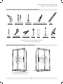
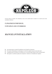
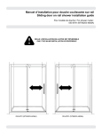
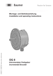
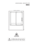
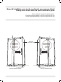
DRILL
1/4" & 1/8" DRILL BITS
SCREWDRIVER
LONG NOSE LOCKING PLIERS (X2)
LEVEL
PERCEUSE
MÈCHE 1/4" & 1/8"
TOURNEVIS
PINCE SERRE ÉTAU (X2)
NIVEAU
Manuel d’installation pour douche coulissante avec panneau latéral
Sliding door shower with side panel installation guide
Pour modèle de douche / For shower model :
053-6824 (NTK6203-4836R) + 053-6790 (NTK6203FP-36)
053-6815 (NTK6203-4836L) + 053-6790 (NTK6203FP-36)
PENCIL
TAPE MEASURE
CUTTING PLIERS
MALLET
BLOCK
WRENCH
SILICONE
CRAYON
RUBAN À MESURER
PINCE COUPANTE
MAILLET
BLOC
CLÉ À FOURCHE
SCELLANT
* Use a ¼" drill bit when drilling into ceramic tiles
* Utiliser une mèche de ¼" pour percer des tuiles en céramique.
POSSIBLE CONFIGURATIONS
/ CONFIGURATIONS
POSSIBLES
POSSIBLE CONFIGURATIONS
/ CONFIGURATIONS
POSSIBLES
*
053-6790
(NTK6203FP-36)
*
*
053-6824 (NTK6203-4836R)
053-6815 (NTK6203-4836L)
Manuel d’installation pour douche coulissante sur rail
Sliding door on rail shower installation guide
NOTES / NOTES
Veuillez conserver ce manuel et le code de produit pour des références futures,
et au besoin, la commande de pièces de rechange.
Please keep this manual and product code number for future reference
and for ordering replacement parts if necessary.
INSTRUCTIONS GÉNÉRALES
GENERAL INSTRUCTIONS
Lire attentivement et complètement le manuel d’installation avant
de procéder.
Read this manu al carefully and completely before proceeding.
It is recommended that you wear safety glasses at all times
during the installation.
Il est recommandé de porter des lunettes de sécurité en tout
temps lors de l’installation.
INSTALLATION OVER CERAMIC TILES
INSTALLATION SUR LES TUILES EN CÉRAMIQUE
If your shower door is to be installed over ceramic tiles, the tiles
should lay completely under the wall jamb.
Si votre porte de douche doit être installée sur une bordure en
céramique, le jambage doit reposer complètement sur cette
dernière.
Silicone should be used to seal the gap where the ceramic tiles
meet the fixed panel.
Le calfeutrage doit être appliqué sur le côté extérieur de la
douche où le panneau fixe rencontre la bordure en céramique.
NOTICE
NOTE
Caulking: n
o sealant is required inside the shower,
unless otherwise stated.
Calfeutrage: aucun scellant n’est nécessaire à l’intérieur
de la douche.
Some models are equipped with clear sealing gaskets.
Certains modèles sont dotés de joints d’étanchéité clairs.
L’ENTRETIEN DE VOTRE DOUCHE
CARE FOR YOUR SHOWER DOOR
Ne jamais utiliser de poudre ou de tampon à récurer, ni
d’instrument tranchant sur les parties en métal ou en verre.
De temps à autre, il suffit de nettoyer la porte avec une solution
d’eau et un détergent doux pour conserver l’aspect neuf des
panneaux de verre et du cadre en aluminium.
Never use scouring powder pads or sharp instruments on metal
pieces or glass panels. An occasional wiping down with a mild
soap diluted in water is ail that is needed to keep the panels
and aluminum parts looking new.
We recommend wiping the glass panels with a squeegee
after each use.
Nous recommandons de passer une raclette de douche sur les
panneaux de verre après chaque utilisation.
Des changements peuvent être apportés au produit sans préavis.
Product specifications are subject to change without notice
2
Manuel d’installation pour douche coulissante sur rail
Sliding door on rail shower installation guide
TOOLS AND MATERIAL REQUIRED / OUTILS ET MATÉRIAUX REQUIS
OUTILS ET MATÉRIAUX REQUIS / TOOLS AND MATERIALS REQUIRED
TOOLS AND MATERIAL REQUIRED
OUTILS ET REQUIRED
MATÉRIAUX/ REQUIS
TOOLS AND/ MATERIAL
OUTILS ET MATÉRIAUX REQUIS
*
DRILL
1/4" & 1/8" DRILL BITS
PERCEUSE
DRILL
DRILL
PERCEUSE
PERCEUSE
PENCIL
**
MÈCHE
1/4"
& 1/8"BITS
1/4"
& 1/8"
DRILL
1/4" & 1/8" DRILL BITS
MÈCHE 1/4" & 1/8"
MÈCHE 1/4" & 1/8"
TAPE MEASURE
CRAYON
PENCIL
PENCIL
CRAYON
CRAYON
RUBAN
À MEASURE
MESURER
TAPE
TAPE MEASURE
RUBAN À MESURER
RUBAN À MESURER
SCREWDRIVER
LONG NOSE LOCKING PLIERS (X2)
TOURNEVIS
SCREWDRIVER
SCREWDRIVER
TOURNEVIS
TOURNEVIS
PINCE
SERRE
ÉTAUPLIERS
(X2) (X2)
LONG
NOSE
LOCKING
LONG NOSE LOCKING PLIERS (X2)
PINCE SERRE ÉTAU (X2)
PINCE SERRE ÉTAU (X2)
CUTTING PLIERS
PINCE
COUPANTE
CUTTING
PLIERS
CUTTING PLIERS
PINCE COUPANTE
PINCE COUPANTE
MALLET
MAILLET
MALLET
MALLET
MAILLET
MAILLET
BLOCK
WRENCH
POSSIBLE CONFIGURATIONS
/ CONFIGURATIONS
POSSIBLES
POSSIBLE CONFIGURATIONS
/ CONFIGURATIONS
POSSIBLES
POSSIBLE
CONFIGURATIONS
/ CONFIGURATIONS
POSSIBLESPOSSIBLES
POSSIBLE CONFIGURATIONS
/ CONFIGURATIONS
POSSIBLES
POSSIBLE
CONFIGURATIONS
/ CONFIGURATIONS
*
**
*
**
*
**
* Cette configuration est illustrée dans ce manuel.
* This configuration illustrated in this manual.
3
NIVEAU
LEVEL
LEVEL
NIVEAU
NIVEAU
BLOC
FOURCHE
BLOCK CLÉ ÀWRENCH
BLOCK
WRENCH
BLOC
CLÉ À FOURCHE
BLOC
CLÉ À FOURCHE
* Use a ¼" drill bit when drilling into ceramic tiles
* Utiliser
une amèche
de bit
¼" when
pour percer
des
tuiles
en céramique.
** Utiliser
Use
¼" drill
drilling
into
ceramic
tiles
de 1/4”
percer
desinto
tuiles
en céramique..
*une
Usemèche
a ¼" drill
bit pour
when
drilling
ceramic
tiles
* Utiliser* Utiliser
une
mèche
de
¼"
pour
percer
des
tuiles
en
céramique.
* Use
a 1/4”
drill de
bit when
drilling
intodes
ceramic
une
mèche
¼" pour
percer
tuilestiles.
en céramique.
CONFIGURATIONS POSSIBLES / POSSIBLE CONFIGURATION
LEVEL
SILICONE
SCELLANT
SILICONE
SILICONE
SCELLANT
SCELLANT
Manuel d’installation pour douche coulissante sur rail
Sliding door on rail shower installation guide
LISTE DES PIÈCES / PARTS LIST
20
13
12
15
5
3
13
11
21
6
1
16
22
1
29
19
23
10
9
24
28
25
26
8
18
17
L
L
R
Number
Spare part code
1
3
5
6
8
9
10
11
12
13
15
16
17
18
19
20
21
22
23
24
25
26
28
29
NTK-6203-1
NTK-6203-22
NTK-6203-2
NTK-6203-4
NTK-6203-10
NTK-6203-21
NTK-6203-20
NTK-6203-6
NTK-6203-5
NTK-6203-24
NTK-6203-23
NTK-6203-7
NTK-6203-9
NTK-6203-11
NTK-6203-8
NTK-6203-12
NTK-6203-15
NTK-6203-13
NTK-6203-14
NTK-6203-18
NTK-6203-17
NTK-6203-16
NTK-6203-2
NTK-6203-25
R
Description
QTY
WALL JAMB / JAMBAGE
MID GASKET / JOINT DU CENTRE
FIXED PANEL GASKET / JOINT DU PANNEAU FIXE
DOOR GASKET / JOINT DE PORTE
ALUMINUM THRESHOLD / SEUIL DE RETENTION
DOOR PANEL / PANNEAU DE PORTE
FIXED PANEL / PANNEAU FIXE
ROLLERS / ROULETTES
RUNNING RAIL / BARRE DE ROULEMENT
WALL MOUNT BRACKET / SUPPORT MURAL
GLASS FASTENER / FIXATION DE VERRE
ANTI-JUMP / ANTI-SAUT
BOTTOM GUIDE / GUIDE INFERIEUR
DOOR RECEIVER / RECEPTEUR DE PORTE
DOOR HANDLE / POIGNEE DE PORTE
WALL PLUG / CHEVILLE
EXPANDER SCREW WITH CAP / VIS POUR L’EXTENSEUR AVEC BOUCHON
WALL JAMB SCREW / VIS POUR JAMBAGE
FLAT HEAD SCREW / VIS A TETE PLATE
3 mm DRILL BIT / FORËT DE 3 mm
HEX SOCKET SET SCREW / VIS A TETE HEXAGONALE
HEX KEY / CLÉ HEXAGONALE
RETURN PANEL / PANNEAU DE RETOUR
GLASS MOUNT BRACKET / SUPPORT DE VERRE POUR PANNEAU DE RETOUR
4
2
1
1
1
1
1
1
2
1
1
2
2
1
1
2
12
8
10
2
1
2
1
1
1
Manuel d’installation pour douche coulissante sur rail
Sliding door on rail shower installation guide
INSTRUCTION MANUAL - GUIDE D’INSTALLATION
INSTRUCTION MANUAL - GUIDE D’INSTALLATION
1. INSTALLATION DES JAMBAGES / WALL JAMB INSTALLATION
1
WALL JAMB INSTALLATIONS / INSATLLATION DES JAMBAGES
Utiliser le tableau de référence pour identifier
JAMB“A”
INSTALLATIONS
/ INSATLLATION DES JAMBAGES
1A1 les WALL
dimensions
et “B” qui
s’accordent
reference
table,
identify the “A”
1a Using the
DIM A = FRONT OPENING
1A
1a
and
“B”
dimensions
that
relate
to your
à votre modèle.
OUVERTURE DU DEVANT
model.
Using the reference table, identify the “A”
1a Mesurer
et marquer sur le seuil de la base les 1a
and “B” dimensions that relate to your
1B dimensions
minimum
et maximum
qui ont of
été
Measure
and mark
on the threshold
the
model.
1b
déterminées
points dimenindiquent
baseantérieurement.
the minumum andCes
maximum
determined
The
la Measure
positionsions
recommandée
pour l’installation
des
and
mark on thepreviously.
threshold
of
theset points
1b
the recommended
base thelocate
minumum
and maximumposition
dimen- for the
panneaux.
DIM A = FRONT
MIN OPENINGMAX DIM B = SIDE
MINOPENING MAX
OUVERTURE DU DEVANT
OUVERTURE DU CÔTÉ
46"
47"
34"
35"
MIN
MAX
MIN
MAX
46"
panel installation.
sions determined
previously. The set points
Tracer
de centre
entre for
lesthe
points du
locateune
the ligne
recommended
position
1C minimum
et maximum
jusqu’au
murset
et points
la continuer
Trace
a centerline
within the
and
panel
1c installation.
1b
runleit mur
up the
usingun
a level,
making
sure
en montant
enwalls
utilisant
niveau.
S’assurant
the
guide
can
be
properly
positioned
on
the
Trace a centerline
within
the set points positionné
and
peut être
correctement
sur
1c que le guide
base
asindiqué.
shown.
it up
the walls
using a level, making sure
la run
base
comme
the guide can be properly positioned on the
base as shown.
1a
47"
34"
35"
1B
1b
TOP VIEW
VU DU HAUT
1athe reference table, identify the “A” and “B”
Using
les dimensions “A” et “B” qui s’accordent à
dimensions
that
relate to your modet.
votre
modèle.
Min
Max
(DIM B )
Min
Max
(DIM B )
1A
DIM B = SIDE OPENING
OUVERTURE DU CÔTÉ
TOP VIEW
les dimensions
“A” et
s’accordent
à base the VU DU HAUT
Measure
and mark
on“B”
thequi
threshold
of the
Mesurer et marquer sur le seuil de la base
votre
1B minimum
1b modèle.
and
maximum
dimensions
determined
les dimensions minimum et maximum qui ont
previously
The
set points
locate
the recommended
déterminées
antérieurement.
Ces points
Mesurerété
et marquer
sur le
seuil de la base
1b position for
the panel
installation.
indiquent
la position
recommandée
pour
les dimensions
minimum
et maximum
qui ont
l’installation
des panneaux.
été
déterminées
antérieurement.
Ces
points
Trace a center line within the set points and run it
la position recommandée pour
1C upindiquent
the walls
using
aligne
level,
sureles
thepoints
guide
Tracer
demaking
centre entre
l’installation
desune
panneaux.
1c
can be properly
positioned
on
the
base
as
du minimum et maximum jusqu’au murshown.
et la
continuer
encentre
montant
le mur
en utilisant un
Tracer une
ligne de
entre
les points
1c
1c
niveau.
S’assurantjusqu’au
que le guide
peut
du minimum
et maximum
mur et
la être
correctement
sur la base
continuer
en montant positionné
le mur en utilisant
un comme
1c
1C
niveau. indiqué.
S’assurant que le guide peut être
correctement positionné sur la base comme
SIDE VIEW
indiqué.
X
X
Min
Max
Min (DIM A)
Max
(DIM A)
X
X
X
X
VUE LATÉRALE
1c
1c
1C
SIDE VIEW
VUE LATÉRALE
ing
o pe n
S ide
côté
u
ure d
t
r
g
e
in
v
o pOeun
S ide
é
u côt
B)
ure d (DIM
uvert
O
Centerline
B)
Ligne de centre
(DIM
Centerline
Ligne de centre
Fron
Ouv ( t open
ing
erDtuIM
re A
du) d
Fron
eva
nt /
Ouv ( t open
erDtuIM (D ing
re A
du) dIM A) Fr
o
eva
nt / nt ope
ning
(DIM
A) Fro
nt o
pen
ing
INTERIOR
SHOWER SIDE
INTÉRIEUR DE
INTERIOR
LA DOUCHE
SHOWER SIDE
INTÉRIEUR DE
LA DOUCHE
TOP VIEW
THE BOTTOM GUIDE CAN HANG OFF THE BASE
VUE DU HAUT
AS LONG AS IT CAN BE WELL FASTENED AND IS
TOWARDS THE INSIDE OF THE SHOWER.TOP VIEW
THE BOTTOM GUIDE CAN HANG OFF THE BASE
VUE DU HAUT
LEAS
GUIDE
INFÉRIEUR
DÉPASSER
LA BASE EN
AS LONG
IT CAN
BE WELLPEUT
FASTENED
AND IS
AUTANT
PUISSE
ÊTRE
BIEN FIXÉ ET QUE
TOWARDS
THEQU’IL
INSIDE
OF THE
SHOWER.
ET C’EST VERS L’INTÉRIEUR DE LA DOUCHE.
LE GUIDE INFÉRIEUR PEUT DÉPASSER LA BASE EN
AUTANT QU’IL PUISSE ÊTRE BIEN FIXÉ ET QUE
ET C’EST VERS L’INTÉRIEUR DE LA DOUCHE.
17
THE INSTALLATION SHOWN IS BASED ON PLUMB FINISHED WALLS
AND A LEVELLED BASE. IF THESE CONDITIONS ARE NOT MET,
PLEASE ADJUST ACCORDINGLY.
THE INSTALLATION SHOWN IS BASED ON PLUMB FINISHED WALLS
AND A LEVELLED
BASE. IFILLUSTRÉE
THESE CONDITIONS
ARE
NOT
L’INSTALLATION
EST BASÉE
SUR
DESMET,
MURS FINIS
PLEASE
ADJUST
ACCORDINGLY.
D’APLOMB
ET UNE
BASE DE
DOUCHE NIVELÉE. SI CES CONDITIONS
NE SONT PAS PRÉSENTÉES, VEUILLEZ AJUSTER EN CONSÉQUENCE.
L’INSTALLATION ILLUSTRÉE EST BASÉE SUR DES MURS FINIS
D’APLOMB ET UNE BASE DE DOUCHE NIVELÉE. SI CES CONDITIONS
NE SONT PAS PRÉSENTÉES, VEUILLEZ AJUSTER EN CONSÉQUENCE.
17
5
5
5
Manuel d’installation pour douche coulissante sur rail
INSTRUCTION
MANUAL
- GUIDE
D’INSTALLATION
Sliding door on
rail shower
installation
guide
2. ASSEMBLAGE
LA PORTE
COULISSANTE
/ SLIDING DE
DOOR
PANELCOULISSANTE
ASSEMBLY
2 DE
DOOR
PANEL ASSEMBLY
/ ASSEMBLAGE
LA PORTE
INSTRUCTION MANUAL - GUIDE D’INSTALLATION
2
2A
2B2a
2A2b
2B
2a
Installer
les deux
roulettes
(11)
à travers
lesthe
deux
Install
both rollers
(11)
through
top
DOOR PANEL
ASSEMBLY
/ ASSEMBLAGE
DE LA PORTE COULISSANTE
2a
holes
the door panel.
Be sure
that the
trous supérieurs
duofpanneau
de porte.
Assurezadjustment
wheel is
to position
vous que l’épaisseur
minimum
deturned
la roulette
the positionnée
minimum thickness
wheel towards
d’ajustement est
vers leofbas.
the bottom.
Installez
la rollers
poignée
porte (19).
Les trous de vis
Install
both
(11)dethrough
the top
se trouvent
sur
la
poignée
intérieure
deThe
la douche.
Install
theBe
door
handle
(19).
holes for
holes
of the
panel.
sure
that the
2b door
the screws
aretolocated
on the back hanadjustment wheel
is turned
position
dle and must
be located
the minimum thickness
of wheel
towardsin the interior of
the shower door.
the bottom.
9
9
DOOR HANDLE HOLES
TROUS DE POIGNÉE DE PORTE
Installthe
bath
rollers
(11)
through
thefor
top hales of the
Install
door
handle
(19).
The holes
DOOR HANDLE HOLES
the
screws
are
on the
handoor
panel.
Belocated
sure that
theback
adjustment
wheel isTROUS DE POIGNÉE DE PORTE
Installer
les
deux
roulettes
(11)
dans
les
dle
and ta
must
be located
in the interior
of
2a
turned
position
the minimum
thickness
of wheel
deux trous supérieurs du panneau de la
the
shower
door.
towards
the
bottom.
porte. Assurer que l’épaisseur minimum
de la roulette
d’ajustement
est are
positionInstall door handle
(19). Hales
for screws
vershandle
le bas. and must be located in
located on thenée
back
Installer
les deux
dans les
the interior
of theroulettes
shower(11)
door.
2a
Installerdu
la panneau
poignée de
deux trous2bsupérieurs
de la
la porte (19). Les
trousl’épaisseur
de vis se trouvent
sur la poignée
porte. Assurer que
minimum
intérieure de est
la douche.
de la roulette d’ajustement
positionINTERIOR
née vers le bas.
INTERIOR
SHOWER SIDE
INTÉRIEUR DE
LA DOUCHE
SHOWER SIDE
2b
Installer la poignée de la porte (19). Les
trous de vis se trouvent sur la poignée
intérieure de la douche.
2a
INTÉRIEUR DE
LA DOUCHE
11
11
2b
THE INSTALLATION SHOWN IS BASED ON
PLUMB FINISHED WALLS AND A LEVELLED
BASE. IF THESE CONDITIONS ARE NOT MET,
PLEASE ADJUST ACCORDINGLY.
2b
INTÉRIEUR DE
LA DOUCHE
INTERIOR
SHOWER SIDE
L’INSTALLATION ILLUSTRÉE EST BASÉE SUR
THE INSTALLATION
IS BASED
ON ET UNE BASE DE
DESSHOWN
MURS FINIS
D’APLOMB
PLUMB FINISHED WALLS
AND
A LEVELLED
DOUCHE
NIVELÉE.
SI CES CONDITIONS NE
BASE. IF THESE CONDITIONS
ARE
NOT
MET,
SONT PAS PRÉSENTÉES, VEUILLEZ AJUSTER
PLEASE ADJUST ACCORDINGLY.
EN CONSÉQUENCE.
INTÉRIEUR DE
LA DOUCHE
L’INSTALLATION ILLUSTRÉE EST BASÉE SUR
DES MURS FINIS D’APLOMB ET UNE BASE DE
DOUCHE NIVELÉE. SI CES CONDITIONS NE
SONT PAS PRÉSENTÉES, VEUILLEZ AJUSTER
EN CONSÉQUENCE.
6
6
19
INTERIOR
SHOWER SIDE
6
19
Manuel d’installation
pour
sur
rail
INSTRUCTION
INSTRUCTION
MANUAL
MANUAL
-G
U-ID
Gdouche
EUIDD’E
IND
Scoulissante
’TIN
AS
LL
TAT
LILOANT
ION
Sliding door on rail shower installation guide
3 3WALL
WALL
JAMB
JAMB
INSTALLATION
INSTALLATION
INSTALLATION
/ INSTALLATION
DU JAMBAGE
DU JAMBAGE
3. INSTALLATION
DU
JAMBAGE
// WALL
JAMB INSTALLATION
3A
3B
Center
Center
wall
the jambs
wall jambs
on the
online
themarked
lineligne
marked
previously
previously
on on
lesthe
jambages
centrés
sur
la
tracée
3a Poser
3a
the threshold
the threshold
insur
theinle
recommended
the
recommended
area area
for
the
forla
shower
the
shower
précédemment
seuil
de la base
dans
zone
door door
instalation
instalation
and align
and align
themthem
using
alalevel.
a level.
recommandée
pour
l’installation
deusing
porte
de
douche et les aligner à l’aide d’un niveau.
MarkMark
the four
the holes
four holes
for both
for both
walls.walls.
Remove
Remove
the wall
the wall
3b 3b
jambs.
jambs.
Tracer
les quatre trous sur le mur sur les deux côtés.
3c
3C
3a 3A
3a
Mettre les jambages de côté.
Drill the
Drillholes
the holes
in theinwall
the with
wall a
with
Ø1/4"
a Ø1/4"
drill bit
drillintented
bit intented
3c
Percer
lesceramic
trous
for ceramic
for
tilingavec
tiling
.
.une mèche à céramique
de ø1/4”.
1
Poser
Poser
les jambages
les jambages
centrés
centrés
sur lasur
ligne
la ligne
tracée
tracée
3a 3a
précédemment
précédemment
sur lesur
seuil
seuil
de la
de
base
la base
dansdans
la
zone
la zone
Center
the wall jambs
onle the
line
marked
previously
recommandée
pour pour
l’installation
l’installation
de lade
porte
la porte
de douche
douche
3A onrecommandée
the threshold in the recommended area fordethe
et lesetaligner
les aligner
à l’aide
à l’aide
d’un d’un
niveau.
niveau.
shower door instalation and align them using a level.
1
1
1
3b the four holes for both wells,
3B 3b Mark
Mettre
Mettre
les jambages
les jambages
de côté.
de côté.
Tracer
Tracer
les quatre
les quatre
troustrous
sur lesur
mur
le sur
murles
surdeux
les deux
côtés.
côtés.
Remove the wall jambs.
3C
Percer
Percer
les trous
les
avecwall
avec
unewith
mèche
une amèche
à céramique
àdrill
céramique
the
holes
introus
the
ø1/4”
bit
3c Drill
3c
de Ø1/4".
de Ø1/4".
intended
for ceramic tiling.
3c 3c
3C
3B 3b
3b
7
7
7
Manuel d’installation pour douche coulissante sur rail
INSTRUCTION MANUAL - GUIDE D’INSTALLATION
Sliding door on rail shower installation guide
INSTRUCTION MANUAL - GUIDE D’INSTALLATION
3 WALL JAMB
INSTALLATION
/ INSTALLATION
DU INSTALLATION
JAMBAGE
3. INSTALLATION
DU JAMBAGE
(SUITE)
/ WALL JAMB
(CONTINUED)
3 Introduire
WALLInsert
JAMB
INSTALLATION
INSTALLATION
JAMBAGE
drop of
in/ dans
each
wall
hole before
uneone
goutte
desilicone
silicone
chaque
trouDUinserting
3d
3d
3D percé dans
3D
the wall
plug.avant
(x8) d’y insérer une cheville. (x8)
le mur
Appliquer
silicone
lain
base
jambages
de
la the side that
Insert Apply
onedu
drop
of silicone
eachdes
wall
hole
before
inserting
silicone
at àthe
bottom
of
both
wall
jambs
on
3e
3E3d côte
the extérieur
wall
plug.
(x8)
sur lathe
surface
fait face
au mur
goes
against
wall asqui
illustrated.
(x2)
3d
tel qu’illustré. (x2)
Apply
silicone at the
of both
wallline
jambs
on the side
that Enthe bottom
wall jambs
on the
previously
marked.
3f Reposition
3e Repositionnez
leswall
jambages
au centre
de laonto the wall
goes against
the
as illustrated.
(x2) du
sure verticality
with
the level.
Screw
theseuil
wall jamb
3F base. Assurer
la verticalité
avec le niveau. Visser les
using 1 3/8"
screws . (x8)
Reposition
the
wall
jambs
on
the line previously
marked.
jambages
au
mur
à
l’emplacement
des chevilles
en En3f
sure verticality
the
level.
Screw
the wall
silicone
on(x8)
the inside
of the
the wall
wall jamb
jambsonto
as illustrated.
utilisant
les vis
1with
3/8”.
3g Apply
using 1 3/8" screws . (x8)
20
Appliquez du silicone à l’intérieur des jambages
tel qu’illustré.
silicone onune
thegoutte
inside de
of the
wall jambs
as illustrated.
silicone
dans chaque
trou percé dans
3g Apply Introduire
3G
3d
20
le mur avant d’y insérer une cheville. (x8)
Introduire
une goutte
de silicone
danswall
chaque
percé
Appliquer
dusilicone
silicone
àinlaeach
base
des
jambages
de la dans
côte extéridrop
of
holetrou
before
3d Insert
3e one
le mureur
avant
d’y
insérer une
cheville.
(x8)
surwall
la surface
qui fait
face au
mur tel qu’illustré. (x2)
inserting
the
pluq. (x8)
3D
Appliquer
du silicone
à lajambages
baseofdes
jambages
deseuil
la on
côte
Repositionnez
au
centre
du
de extérila base.
Apply
silicone
at the les
bottom
both
wall jambs
3f
3E3e eur
surAssurer
la surface
qui
fait face
telillustrated.
qu’illustré.
la verticalité
avec
lemur
niveau.
Visser les(x2)
jambages au
the side
that
goes
against
theauwall
as
(x2)
mur à l’emplacement des chevilles en utilisant les vis 1 3/8".
3F 3f
Reposition
jambs onauthe
linedu
previously
Repositionnez
les jambages
centre
seuil de la base.
(x8) the wall
Assurer Ensure
la verticalité
avec lewith
niveau.
jambages
marked.
verticality
the Visser
tevel. les
Screw
the au
murjamb
à l’emplacement
desusing
chevilles
en screws.
utilisant
les
vis 1tel
3/8".
duwall
silicone
à l’intérieur
des jambages
qu’illustré.
wall
onto the
1 3/8”
(x8)
3g Appliquez
(x8)
Apply silicone on the inside of the wall jambs
illustrated.
du silicone à l’intérieur des jambages tel qu’illustré.
3g asAppliquez
3G
3f
3e
3e
3E
3f
3F
INTERIOR
SHOWER SIDE
INTÉRIEUR DE
LA DOUCHE
INTERIOR
SHOWER SIDE
INTÉRIEUR DE
LA DOUCHE
3g
3g
3G
1
1
8
8
8
2e
Place wall jamb against wall using centerline
previously marked as a guide. Be sure to center
WALL JAMB INSTALLATION
the slotted holes with2the centerline.
/ INSTALLAT
INSTRUCTION
MANUAL - G
UIDdouche
E D’INScoulissante
TALLATIONsur rail
Manuel d’installation
pour
Sliding door on rail shower installation guide
2e
2f
2g
2h
2e
2f
2g
2h
Level and mark locations of the four holes to
2e
2f wall
Place
jamb against wall using centerline
be drilled.
3
WALL JAMBmarked
INSTALLATION
JAMBAGE
previously
as /(SUITE)
aINSTALLATION
guide.
BeDU
sure
to center (CONTINUED)
3. INSTALLATION
DU
JAMBAGE
/ WALL
JAMB
INSTALLATION
the slotted holes with the centerline.
panneau fixe (10) et le panneau de retour prémontré de l’extenseur et du joint dans le jambage (1).
3H 3h Glissez le Remove
the wall jamb.
Level the
glassmark
panel assembly
with the wallof
jamb.
Lock four
into position
by clamping
2g
3i
Level
and
locations
the
holes
to the wall jamb and expander with pliers.
Assurer le niveau du panneau fixe à l’aide d’un niveau.
2e
3I be
Barrer
la position du jambage et de l’extenseur à l’aide de pinces autobloquantes.
drilled.
3h
Drill a hole in each location with a 1/4” drill bit.
3H
3I
3i
1
2hautobloquantes.
Slide the fixed panel and the pre-assembled return panel with expander and gasket into the wall jambs (1).
Remove
the wall jamb.
1
Level the glass panel assembly with the wall jemb.
Lock into position by clamping the wall jamb and expander with pliers.
Placez le jambage sur le seuil en centrant les
2e a hole
Drill
in de
each
a 1/4”
drill centrale
bit.
trous
la location
jambièrewith
avec
la ligne
tracée. Ceci assure une position droite du jambage
2f le
Placez
jambage
sur le emplacements
seuil en centrant
Tracez
les quatre
de les
perçage.
trous de la jambière avec la ligne centrale tracée. Ceci assure une position droite du jam2g Enlevez le jambage.
bage
10
28
Tracez les quatre emplacements de perçage.
2h Percez les trous avec une mèche de 1/4”.
Enlevez le jambage.
3i
3I
3H
3h
Percez les trous avec une mèche de 1/4”.
1
10
COVER THE PLIER’S TEETH BEFOREHAND TO
AVOID SCRATCHING THE ALUMINUM PARTS.
RECOUVREZ LES DENTS
DE LA PINCE AFIN DE NE PAS
GRAFIGNER LES PIÈCES EN ALUMINIUM.
2g
9
9
2g
1
Manuel d’installation pour douche coulissante sur rail
Sliding door on rail shower installation guide
MANUAL - GUIDE D’INSTALLATION
4. INSTALLATION DE LA BARRE DE ROULEMENT / RUNNINGINSTRUCTION
RAIL INSTALLATION
4A
4
Positionnez le support mural de rail (13) et le fixer correctement au mur avec les deux vis fournies.
RUNNING RAIL INSTALLATION / INSTALLATION DE LA BARRE DE ROULEMENT
Aligner les trous de la barre de roulement avec les trous du panneau fixe. Installer les supports de verre (15) pour joindre
4B 4a le Position
the
rail(10)
wall à
bracket
(13)de
correctly
and fasten
it to the wall
with the
screws
provided.
panneau
fixe
la barre
roulement
(12). Assurer
d’avoir
un 2joint
situé
aux tout contact entre la vitre et le métal.
4C
4b Serrer à l’aide de la clé hexagonale 3mm.
sure to place the gaskets between all contact with the glass and metal parts.
4c
15
Fasten with 3mm hex key.
Position the rail wall bracket (13) correctly and fasten it to the wall with the 2 screws provided.
4A
4a
Positionnez le support mural de rail (13) et le fixer correctement au mur avec les deux vis fournies.
Align running rail holes with holes in the fixed panel, Install the glass fasteners (15) to join the fixed panel (10) and
4B 4c rail (12), Be sure to place the gaskets between ail contact with the glass and metal parts.
15
3mm
key.
Serrerwith
à l’aide
dehex
la clé
hexagonale 3mm.
4C 4d Fasten
4a
4A
12
13
4b
4B
INTERIOR
SHOWER SIDE
INTÉRIEUR DE
LA DOUCHE
4c
4C
10
INTERIOR
SHOWER SIDE
INTÉRIEUR DE
LA DOUCHE
12
14
10
10
Manuel d’installation pour douche coulissante sur rail
Sliding door on rail shower installation guide
4. INSTALLATION DE LA BARRE DE ROULEMENT (SUITE) / RUNNING RAIL INSTALLATION (CONTINUED)
4D
Insérez le support du rail du panneau de retour et mettre a niveau.INSTRUCTION MANUAL - GUIDE D’INSTALLATION
Enlever les panneaux gardant le panneau fixe assemblé avec la barre de roulement et le poser de côté. Enlever le support
4E mural du panneau fixe.
4 RUNNING RAIL INSTALLATION / INSTALLATION DE LA BARRE DE ROULEMENT
4D4d Install
Installthe
theglass
glass mount
mountbracket.
bracket.
Remove glass panels keeping the running rail still assembled with the fix panel,
4E4e Set aside and remove the glass mount bracket from the fixe panel.
4d
Insérez le support du rail du panneau de retour et mettre a niveau.
4e
4d
4D
INTERIOR
SHOWER SIDE
INTÉRIEUR DE
LA DOUCHE
4E
4e
11
11
Manuel d’installation pour douche coulissante sur rail
Sliding door on rail shower installation guide
5. GUIDE DU BAS / BOTTOM GUIDE
5A
INSTRUCTION MANUAL - GUIDE D’INSTALLATION
Introduire le panneau de porte coulissante (9) à
l’intérieur de la douche afin de simplifier les étapes
7 Poser
BOTTOM
GUIDE /sur
GUIDE
DU BAS
à suivre.
le panneau
une surface
plane et
matelassée comme une serviette ou un carton. Cela
the door
(9) inside
the shower to 7a
évite7atout Place
dommage
au panel
panneau
ou la base.
5A
simplify the following installation procedures.
5B
on a le
cushioned
surface,
Placer le place
guidethe
du panel
bas avec
rebord du
profil such
en
asaligner
a towel le
or centre
cardboard,
to prevent
to
aluminium,
du devant
dudamage
guide avec
the panel
or the base.
le centre either
du profilé
en aluminium.
5C
Place the bottom
edge oflethe
fixeddu
glass
Tracer
duguide
trou.toRetirer
guide
bas.
7b l’emplacement
5D
5E
9
panel and center the front channel of the bottom
the une
center
of the de
glass.
Percer unguide
trou to
avec
mèche
1/8” et puis y
appliquer une goute de silicone.
Once in place, mark the hole location and re7c
move le
theguide
bottom
Repositionner
duguide.
bas et le fixer avec la vis
fournie. Ajouter le capuchon couvre-vis.
7d Drill with a 1/8" drill bit in the marked location,
then apply a drop of silicone in the hole.
5A
5B
suivre. Poser le panneau sur une surPlace theétapes
bottomà guide
to edge of the fixed glass
face plane et matelassée comme une serviette
panel and center the front channel of the bottom
ou un carton. Cela évite tout dommage au panguide to the
center
of the glass.
neau
ou la base.
5C
Once in place, mark the hole location and remove the
7b guide.
bottom
5D
5E
!!
and secure
Place
door panelthe
(9)bottom
insideguide
the shower
to III it in
7etheReposition
place.
Top with
screw cap.procedures. place
simplify the
following
installation
the panel on a cushioned surface, such as a towel or
cardboard, to pre vent damage to either the panel or
7a Introduire le panneau de porte coulissante (9)
the base.
CARBOARD OR TOWEL
TO PROTECT
CARTON OU SERVIETTE POUR PROTÉGER
INTERIOR
SHOWER SIDE
en aluminium, aligner le centre du devant du
Drill with a 1/8” drill bit in the marked location, then
apply a drop
of l’emplacement
silicone in thedu
hote.
Tracer
trou. Retirer le guide
7c
du bas.
Reposition the bottom guide and secure it in place.
Top with screw
cap.
7d Percer un trou avec une mèche de 1/8" et puis
INTÉRIEUR DE
LA DOUCHE
5B
7b
y appliquer une goute de silicone.
7e
la vis fournie. Ajouter le capuchon couvre-vis.
5C
7c
5D
7d
INTERIOR
SHOWER SIDE
INTERIOR
SHOWER SIDE
INTÉRIEUR DE
LA DOUCHE
INTÉRIEUR DE
LA DOUCHE
CERAMIC TILE INSTALLAITON, USE A
BIT FOR CERAMIC TILE.
INSTALLATION POUR CARREAUX EN
CÉRAMIQUE, UTILISÉ UNE MÈCHE POUR
TUILE EN CÉRAMIQUE.
12
13
lace wall jamb against wall using centerline
reviously marked as a guide. Be sure to center
e slotted holes with the centerline.
2
Manuel d’installation pour douche coulissante sur rail
Sliding door on rail shower installation guide
WALL JAMB INSTALLATION / INSTALLATION DES JAMB
evel and mark locations of the four holes to
2e
e drilled. 6. INSTALLATION DES PANNEAUX / PANEL INSTALLATIONINSTRUCTION MANUAL - GUIDE D’INSTALLATION
wall jamb against wall using centerline
le panneau
Mettre
niveau en assurant
usly marked
asInstaller
a guide.
Be fix.
sure
toà center
6A
que
le
bout
ne
dépasse
pas
le
rebord
du guide
de
PANNEL INSTALLATION / INSTALLATION
DES PANNEAUX
otted holes8 with
the centerline.
bas.
emove the wall jamb.
1
Barrer la position des jambages et des
and mark8a6B
locations
the
four
holes
to
extenseurs
l’aide
pinces
autobloquantes.
panel.
Be sureof
toàlevel
thedes
panels
and
led.
end of the
bottom guide.with a 1/4” drill bit.
rill a hole in each
location
2f
2f
2e
Reinstall the fixed panel and return panel. Be sure to
into position by clamping the
8b6ALocklevel
the panels and align the fixed panel edge with
wall jambs and expanders with pliers.
the end of the bottom guide.
ve the wall jamb.
1
Lock into position by clamping the wall
8a6B
jambs
and expanders
with
niveau
en assurant
que le bout
nepliers.
dé-
lacez le jambage sur le seuil en centrant les
passe pas leavec
rebord du
de bas.
ous de la jambière
laguide
ligne
centrale trahole in each location with a 1/4” drill bit.
ée. Ceci assure
une position droite du jam8b Barrer la position des jambages et
des extenseurs à l’aide des pinces
age
autobloquantes.
10
28
racez les quatre emplacements de perçage.
z le jambage sur le seuil en centrant les
de la jambière avec la ligne centrale traCeci assure une position droite du jamnlevez le jambage.
10
z les quatre emplacements de perçage.
ercez les trous avec une mèche de 1/4”.
INTERIOR
SHOWER SIDE
INTÉRIEUR DE
LA DOUCHE
ez le jambage.
z les trous avec une mèche de 1/4”.
COVER THE PLIER’S TEETH BEFOREHAND TO AVOID
SCRATCHING THE ALUMINUM PARTS.
2g
14
RECOUVREZ LES DENTS DE LA PINCE AFIN DE NE PAS
GRAFIGNER LES PIÈCES EN ALUMINIUM.
2h
13
2g
1
2h
Manuel d’installation pour douche coulissante sur rail
Sliding door on rail shower installation guide
7. BARRE DE ROULEMENT / RUNNING RAIL
Glisser les supports muraux contre le mur. Insérés les dans les plaquettes arrières déjà montés au mur. Répéter sur le côté
opposé avec le support de verre.
7A
7B
7A
7B
INSTRUCTION MANUAL - GUIDE D’INSTALLATION
9
9a
9b
RUNNING RAIL / BARRE DE ROULEMENT
Serrer les vis pour sécuriser l’emplacement des supports. (X8)
With the back plate previsouly secured to the wall, push the wall brackets towards the wall and lock it in. Repeat on the opposite side
withthe
the back
glass plate
bracket.
With
previously secured to the wall, push the wall brackets towards the wall and lock it in. Repeat on the
opposite
side
with
the
glass
bracket.
Tighten the set screws to
secure
in place with the allen key provided. (X8)
Tighten the set screws to secure in place with the allen key provided. (X8)
9a
Glisser les supports muraux contre le mur. Insérés les dans les plaquettes arrières déjà montés au mur. Répéter sur le côté opposé
avec le support de verre.
9b
Serrer les vis pour sécuriser l’emplacement des supports. (X8)
7A
9a
7B
9b
TOP VIEW
VU DU HAUT
INTERIOR
SHOWER SIDE
INTÉRIEUR DE
LA DOUCHE
14
15
Manuel d’installation pour douche coulissante sur rail
INSTRUCTION
MANUAL
- GUIDE
D’INSTALLATION
Sliding
door on rail
shower
installation guide
8. JAMBAGE
ET EXTENSEUR
/ WALL JAMB
ANDET
EXPANDER
10 WALL
JAMB AND EXPANDER
/ JAMBAGE
EXTENSEUR INSTRUCTION MANUAL - GUIDE D’INSTALLATION
6A
Drill through àthe
wall jamb
a 1/8" drill bit to
Percer
travers
les holes
trouswith
du jambage
10a l’extenseur
pierce
through
the expander.
(x4)/ JAMBAGE ET EXTENSEUR
avec
mèche
deAND
1/8”.
(x4)
10 une
WALL
JAMB
EXPANDER
6B
Screw
3/4"3/4”
screws
thepour
holestenir
to hold
Visser
vis de
(21) (21)
dansthrough
les trous
10b les
theand
wall wall
jamb
holestogether
with a 1/8"
drill bit(x3)
to
thethrough
expander
jamb
in place.
10a Drill
l’extenseur
et le jambage
ensemble.
pierce
through
the expander.
(x4) caps.
Cover
all
the
screws
with
screw
Couvrir avec les capuchons couvre-vis.
Screw 3/4" screws (21) through the holes to hold
the expander and wall jamb together in place. (x3)
Percer
l’extenseur
à travers
les
trous du jambage
Cover
all
screws
with
screw
caps.
10a
Drill through
thethe
wall
jamb
holes
with
a 1/8” drill bit to
avec une
mèche
de 1/8".
(x4)
10b
6A
pierce through the expander. (x4)
Viser les vis de 3/4" (21) dans les trous pour tenir
10b 3/4” screws (21) through the holes to hold the
Screw
Percer
l’extenseur
à traversensemble.
les trous du
jambage
l’extenseur
et le jambage
Couvrir
avec
10a
expander
jamb
together
avec
une wall
mèche
de 1/8".
(x4) in place. (x3)
lesand
capuchons
couvre-vis.
Cover ail the screws with screw caps.
6B
10b
INTERIOR
SHOWER SIDE
Viser les vis de 3/4" (21) dans les trous pour tenir
l’extenseur et le jambage ensemble. Couvrir avec
les capuchons couvre-vis.
INTÉRIEUR DE
LA DOUCHE
INTERIOR
SHOWER SIDE
INTÉRIEUR DE
LA DOUCHE
21
SAME PROCEDURE FOR RETURN PANEL,
WALL JAMB AND EXPANDER
21 PROCÉDURE POUR PANNEAU DE RETOUR,
MÊME
JAMBAGE ET EXTENSEUR
SAME PROCEDURE FOR RETURN PANEL,
WALL JAMB AND EXPANDER
11 DOOR PANEL INSTALLATION / INSTALLATION DU PANNEAU DE PORTE
9. INSTALLATION
DU PANNEAU DE PORTE / DOOR PANEL INSTALLATION
MÊME PROCÉDURE POUR PANNEAU DE RETOUR,
JAMBAGE ET EXTENSEUR
11a Install the door panel (9) by aligning the rollers
9A
11a 11
Installer
panneau
de porte
(9)and
en by
(11)leon
the running
rail (12)
aligningles
the
DOOR
PANEL
INSTALLATION
/alignant
INSTALLATION
DU PANNEAU DE PORTE
11
door(11)
panel
thede
back
channel of
theet
bot- 10
roulettes
sur(9)lawith
barre
roulement
(12)
tom guide
(17).
en alignant
le panneau
de porte avec le seuil
Install
door du
panel
by aligning the rollers
9A
intérieur
duthe
guide
bas(9)(17).
11a
11a 11
(11) on the running rail (12) and by aligning the
11b Slide the door to ensure a smooth stable glide.
panel
withpour
the back
channel
of the bot- 10
Fairedoor
glisser
la (9)
porte
assurer
l’aise
tom
guide
(17).
avec laquelle la porte glisse sur la barre
Installer le panneau de porte (9) en alignant les
de
11aroulement.
9B
9A
9B
the door
ensure
a smooth
stable glide.
roulettes
(11)tosur
la barre
de roulement
(12) et
11b Slide
en alignant le panneau de porte avec le seuil intérieur du guide du bas (17).
Install
the door panel (9) by aligning the rollers
Installer le panneau de porte (9) en alignant les
11a
(11) roulettes
on the running
rail
(12) and
by aligning
(11) sur
la barre
de assurer
roulement
(12)avec
et
Faire glisser
la porte
pour
l’aise
11bdoor
the
panel
(9)
with
the
back
channel
enlaquelle
alignant
le
panneau
de
porte
avec
seuil inla porte glisse sur la barre
deleroulement.
of thetérieur
bottom
guidedu
(17).
du guide
bas (17).
15
12 9
INTERIOR
SHOWER SIDE
12
SlideFaire
the door
to la
ensure
smooth
stable
glisser
porte apour
assurer
l’aiseglide.
avec
11b
laquelle la porte glisse sur la barre de roulement.
15
INTÉRIEUR DE
LA DOUCHE
9
10
INTERIOR
SHOWER SIDE
INTÉRIEUR DE
LA DOUCHE
179
10
17
16
16
9
9
15
9
10
10
28
28
Manuel
d’installation
pour douche
INSTRUCTION
MANUAL
- GUIcoulissante
DE D’INSTAsur
LLrail
ATION
Sliding door on rail shower installation guide
12 PANNEAU
DOOR GASKETS
/ JOINT/ DE
PANNEAU
DE PORTE
10. JOINT DE
DE PORTE
DOOR
GASKETS
10A
Temporarily install
the latéral
midgasket
(5)leand
Installer
le joint
(5) et
jointthe
de
12atemporairement
gasket (6)de
to the
door panel.
porte (6) surdoor
le panneau
la porte.
10B
Close
door entirely
mark the interferAvec la
porte
bienthe
fermée,
tracerand
l’interférence
des
12b
ence
of the
with the running rail.
joints avec la
barre
degaskets
roulement.
10C
thesur
gasket
at the
marked
locations
Couper
les Cut
joints
la ligne
tracés.
Noter
que lewith
12c
Notecoupé
that the
(5) only
joint latéral cutters.
suffit d’être
à la midgasket
partie inférieure.
needs
to
be
cut
below
the
running
rail.
top
La partie supérieure du joint n’est pas requiseThe
pour
part is no longer required.
l’assemblage.
10D
Reinstall
the bottom
and
Réinstaller
joints the
sur gaskets
la porte,from
débuter
par le bas
12d les
work your way up. Use a mallet to insure that
et puis monter. Utiliser un maillet pour assurer que les
the gaskets are fully pushed onto the glass.
joints soient bien fixés au panneau de porte.
10A
le joint de porte (6) sur le panneau de la
Temporarilyetinstall
the midgasket (5) and the door
porte.
gasket (6) to the door panel.
10B
Close 12b
the door entirely and mark the interference
l’interférence des joints avec la barre de
of the gaskets
with the running rail.
roulement.
12a
10C
10D
12a
10A
5
6
Installer temporairement le joint latéral (5)
Avec la porte bien fermée, tracer
INTERIOR
SHOWER SIDE
INTÉRIEUR DE
LA DOUCHE
12b
10B
5
6
Cut the gasket at the marked locations with cutters.
Couper les joints sur la ligne tracés. Noter
12c the
Note that
midgasket (5) only needs to be cut
below the running
rail. TheLa
toppartie
partsupérieure
is no longer
partie inférieure.
du
required. joint n’est pas requise pour l’assemblage.
Reinstall theRéinstaller
gaskets from
the sur
bottom
anddébuter
work your
les joints
la porte,
12d
way up. Usepar
a le
mallet
insure
that Utiliser
the gaskets
are
bas ettopuis
monter.
un
fully pushedmaillet
onto pour
the glass.
assurer que les joints soient
INTERIOR
SHOWER SIDE
INTÉRIEUR DE
LA DOUCHE
5
12c
10C
6
12d
10D
REMOVE GASKET FROM PANEL BEFORE CUTTING.
RETIRER LE JOINT DU PANNEAU
AVANT DE PROCÉDER À LA COUPURE.
17
16
Manuel d’installation pour douche coulissante sur rail
Sliding door on rail shower installation guide
INSTRUCTION MANUAL - GUIDE D’INSTALLATION
11. INSTALLATION DES ANTI-SAUT / ANTI-JUMP INSTALLATION
Installer
l’Anti-Saut
dansholes
les of
trous
dubelow
panneau
Install Anti-Jump
(16)(16)
in lower
door inférieurs
panel located
the de porte se trouvant dessous la barre de roulement.
running rail. Be
sure todes
placejoints
gaskets
between
glass and
Assurez-vous
d’avoir
entre
tout contact
contactof d’aluminium
et de vitre. (x2)
11A13a
aluminium parts. (x2)
Installer
l’Anti-Saut(16)
(16) in
dans
les trous
inférieurs
du panel
panneau
de portebelow The running rail. Be sure la place gaskets between
Install
Anti-Jump
lower
hales
of door
localed
se trouvant dessous la barre de roulement. Assurez-vous d’avoir des
contact
of
glass
and
aluminium
parts.
(x2)
joints entre tout contact d’aluminium et de vitre. (x2)
11A13a
11A
13a
INTERIOR
SHOWER SIDE
INTÉRIEUR DE
LA DOUCHE
GASKETS
JOINTS
16
16
INTERIOR
SHOWER SIDE
INTÉRIEUR DE
LA DOUCHE
18
17
Manuel d’installation pour douche coulissante sur rail
Sliding door on rail shower installation guide
12. INSTALLATION DU RÉCEPTEUR DE PORTE / DOOR RECEIVER INSTALLATION
12A
12B
12C
12D
12A
12B
12C
12D
PlacerPlace
le récepteur
porte (18)
(18) against
contre le
the doorde
receiver
themur,
wall 14a
14a Place
the
door slides
receiver
(18) the
against
thePlace
door
receiver
(18)
against
wall
placé
en
sorte
que
lapanel
porte
glisse
aisément
dans
lewall 12A
14a
14a
14a
14a
so
that
the
door
smoothly
into
thethe
soMark
thatlethe
the
door
panel
slides
smoothly
into
the
soreceiver.
that Tracer
the
door
panel
slides
smoothly
into
the
récepteur.
trou
du
récepteur.
location of the hole.
the of
location
of the hole.
receiver. receiver.
Mark the Mark
location
the hole.
Retirer le receveur et percer à l’endroit indiqué avec
Remove the door receiver and drill in the
14b mèche
une
1/8”.
Remove
door receiver
drill in the
Removede
the
doorthe
receiver
and drill and
in the
14b
18
18
marked
14b location with a 1/8" drill bit.
marked with
location
with
1/8" drill bit.
marked location
a 1/8"
drilla bit.
Insérer une goutte de silicone dans le trou.
14b
14b
14b
12B
14d
14d
12D
14d
18
Insert one drop of silicone into the hole.
14c Insert
drop ofinto
silicone
into the hole.
dropone
of silicone
the hole.
14c
14coneInsert
Repositionner
et viser la vis pour tenir en place.
Reposition
and
secure
in
place
with
provided
Rajouter
le capuchon
à vis.
14d
Reposition
place
with provided
and
insecure
place
with
provided
screw
capsecure
withand
screw
cap.in
14d Reposition
14d then
screw
cap with
screw cap.
screw then
cap then
with screw
cap.
récepteur de porte (18) contre le mur,
14a Placerlele
Placer
récepteur
de porte
(18)
récepteur
de porte
(18)
contre
le contre
mur, le mur,
placé
sortele que
la porte
glisse
aisément
14a Placer
14a en
placé
en
sorte
que
la
porte
glisse
placé
en
sorte
que
la
porte
glisse
aisément
Place dans
door lereceiver
(18)
against
wall,
saaisément
that
récepteur.
Tracer
le trou
du place
récepteur.
dans
le récepteur.
trou du récepteur.
danspanel
le récepteur.
Tracer
le Tracer
trou
dule
récepteur.
the door
slides
smoothly
into
receiver.
Mark
hole location.
Retirer le receveur et percer à l’endroit indiqué
14b Retirer leRetirer
14c
le receveur
percer à indiqué
l’endroit indiqué
receveur
et perceret
à l’endroit
avec
14b
14b une mèche de 1/8".
12C
14c
14c
unedemèche
de 1/8".
avecdoor
uneavec
mèche
1/8". drill
Remove
receiver
and
in marked location
with 1/8”
drill une
bit. goutte de silicone dans le trou.
Insérer
14c Insérer une
Insérer
une
dedans
silicone
dans le trou.
goutte
degoutte
silicone
le trou.
14c
14c
Insert one drop of silicone into hole.
14d
14d
14d
Rajouter
le capuchon couvre-vis.
Reposition
and
secure
incouvre-vis.
place with
provided screw
Rajouter
Rajouter
le capuchon
le capuchon
couvre-vis.
then cap with screw cap.
13. SEUIL DE RÉTENTION / THRESHOLD
L13A
15a
Placer
le seuil
de rétention
entre return
le murpanel
et le L15a
L15a
Place
threshold
(8) between
15a Place
threshold
Place
threshold
(8) l’indique
between
(8) between
return
panel
return
13A 15a
guide du
comme
la figure
13a. panel
15abas
Couper
l’excès
seuil
pourlength.
que le seuil rentre
15a.
Cut offdu
any
excess
15a. Cut 15a.
off
Cutexcess
off anylength.
excess length.
parfaitement
enany
place.
15b Apply silicone on the bottom of threshold as in-
Appliquer
le Apply
silicone
sous
le
seuil
dein rétention
Apply
on
silicone
the
bottom
on
the
ofbottom
threshold
of threshold
as inas in15bsilicone
dicated
in 15b.
Secure
threshold
place.
13B 15b
et puis
installé
en place.
dicated
indicated
15b.
Secure
in 15b.threshold
Secure threshold
in place. in place.
13A
seuil de rétention entre le mur et le
15a Placerlele
seuil de
le rétention
seuil de rétention
entre le mur
entreetlelemur et le
15a Placer
15a Placer
Couper
l’excès
du
seuil
pour
que
le
seuil entre
PlaceCouper
threshold
(8)du
between
bottom
l’excès
Couper
l’excès
seuil pour
duwall
seuil
queand
pour
le seuil
queentre
le seuil entre
parfaitement.
guideparfaitement.
as shown
in figure 13a. Cut off any
parfaitement.
13B
Appliquer le silicone sous le seuil de rétention
15b Appliquer
le silicone
lesous
silicone
le seuil
sousde
le rétention
seuil de rétention
et
puis Appliquer
l’installer
en
place.
15b
15b
Apply
silicon
on
the bottom
of
threshold
as
et puis l’installer
et puis l’installer
en place.en place.
8
8
excess length.
8
15b
13B
15b
indicated in 13b. Secure threshold in place.
CUT ONLY IF NECESSARY
CUT ONLY
CUT
IF NECESSARY
ONLY IF NECESSARY
COUPER SEULEMENT SI
COUPER
COUPER
SEULEMENT
SEULEMENT
SI
SI
NECESSAIRE
NECESSAIRE
NECESSAIRE
18
INTERIOR
SHOWER
INTERIORSIDE
INTERIOR
SHOWER SIDE
SHOWER SIDE
INTÉRIEUR DE
LA DOUCHE
INTÉRIEUR
DE
INTÉRIEUR DE
LA DOUCHE LA DOUCHE
15b
Manuel d’installation pour douche coulissante sur rail
Sliding door on rail shower installation guide
INSTRUCTION MANUAL - GUIDE D’INSTALLATION
14. CALFEUTRAGE / SEALING
SEALING
/ CALFEUTRAGE
avec
du silicone l’extérieur de l’unité autour du jambage et à l’extérieur du seuil en aluminium.
14A16 Calfeutrer
Silicone the outside of the shower unit along the wall jamb and the exterior side of aluminum threshold.
14B16aAttendre 24 heures avant de faire fonctionner la douche laisser le silicone séché.
Wait 24 hours before using the shower to allow silicone to dry.
14A
Silicone the outside of the shower unit along the wall jamb and the exterior side of aluminum threshold and fixed panel.
14B
Wait 24 hours before using the shower to allow silicon to dry.
16a
14B
HEURES
HOURS
14A
20
19