1
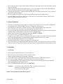
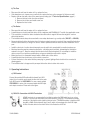
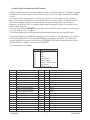
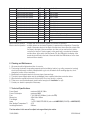
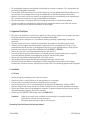
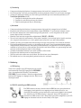
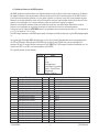
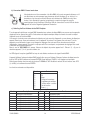
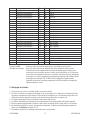
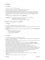
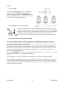
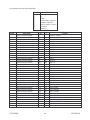
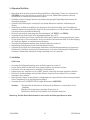
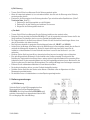
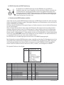
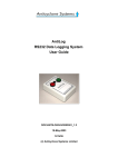
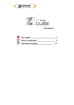
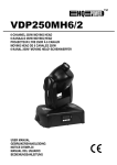
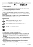
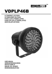
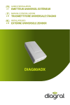
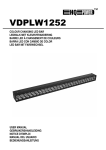
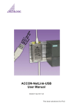
VDP150BR3 – SPACE ROLLER 150
1. Introduction & Features
Thank you for buying the VDP150BR3! Read this manual carefully before bringing the device into service.
The VDP150BR3 features a colour wheel with 13 gobos with 10 colours, 2 bicoloured gobos + white, rainbow effect
and dynamic pan/tilt functions. The device is controlled through 3 DMX channels and creates a fast-changing effect.
Make sure that the device was not damaged in transit. If it was, don’t install the device and contact your dealer.
Features :
•
•
•
•
•
•
•
•
•
Pan 180° / tilt : left – right
13 gobos with 10 colours + 2 bicoloured gobos + white
Shaking gobos and music-controlled gobo change
Strobe: 0~5Hz
Automatic program or music-controlled operation
Display: digital address and function setting
High speed pan & tilt movements
Display turns 180° when necessary
DMX mode, music-controlled mode or master-slave synchro mode
2. Safety Instructions
Be very careful during the installation : touching live wires can
cause life-threatening electroshocks.
Do not touch the device during operation as the housing heats up
Keep this device away from rain and moisture
Unplug the mains lead before opening the housing
• Everyone involved with the installation, operation and maintenance of this device has to be qualified and follow
the instructions of this manual meticulously
• Damage caused by disregarding certain guidelines in this manual is not covered by the warranty and the dealer
will not accept responsibility for the ensuing defects or problems.
• Do not switch the device on immediately if it has been exposed to changes in temperature. Protect the device
against damage by leaving it switched off until it has reached room temperature.
• This device falls under protection class I. It is essential, therefore, that the device be earthed. Have this device
installed by a qualified technician.
• Make sure that the available voltage does not exceed the voltage stated in the specifications of this manual.
VDP150BR3
1
VELLEMAN
• Do not crimp the power cord and protect it against damage from sharp edges. Ask an authorised dealer to replace
the cord if necessary.
• Always disconnect the device from the mains when it is not in use or when you wish to clean it. Only handle the
power cord by the plug. Never pull out the plug by tugging the power cord.
• There may be some smoke or a particular smell when the device is activated for the first time. This is normal and
the smell will gradually disappear.
• Do not look directly at the light source. It may cause sensitive people to go into epileptic seizure.
• Note that damage caused by user modifications to the device is not covered by the warranty. Keep the device
away from children and unauthorised users.
3. General Guidelines
• This device is a light effect for professional use on stage, in discos, theatres, etc. It should only be operated with
an alternating current of 230V AC/50Hz. This device is designed for indoor use only.
• Light effects are not designed for continuous operation : regular operation breaks will prolong their life.
• Do not shake the device. Avoid brute force when installing or operating the device.
• Select a mounting location where the device will be protected against extreme heat, moisture and dust. Respect a
minimum distance of 50cm between the projector and the illuminated surface.
• Always secure the device with an appropriate safety cable (VDLSC7 or VDLSC8).
• Do not use this device in an ambient temperature > 45°C.
• Familiarise yourself with the functions of the device before actually using it. Do not permit operation by unqualified
people. Any damage that may occur will probably be caused by unprofessional use of the device.
• Use the original packaging if the device is to be transported.
• Note that all modifications of the device are forbidden for safety reasons.
• Only use the device for its intended purpose. All other uses may lead to short circuits, burns, electric shock, lamp
explosion, crash, etc. Using the device in an unauthorised way will void the warranty and may damage the device.
4. Installation
a) The Lamp
Use the original packaging if the device is to be transported.
Disconnect the unit from the mains to install or replace the lamp.
Replace the lamp immediately if it’s damaged or deformed.
Let the lamp cool down before replacing it because the lamp can heat up to 700°C during operation.
Do not touch a halogen lamp with your bare hands. Use a cloth to insert or remove it.
Do not install lamps with a higher wattage than that for which the device was designed. Such lamps generate
higher temperatures and may damage the unit.
• Use a 15V/150W EFR GZ6.35 lamp (order code LAMP150/15).
•
•
•
•
•
•
Procedure:
1. Loosen the screws on the bottom of the housing and remove the cover.
2. Remove the old lamp and insert the new one.
3. Close the lid and fix the screws.
Remark: Do not operate the device with an open lid.
VDP150BR3
2
VELLEMAN
b) The Fuse
• Disconnect the unit from the mains to fit or replace the fuse.
• If the lamp burns out, chances are you will need to replace the fuse on the rear panel of the base as well.
• Replace a blown fuse with a fuse of the same type and rating (see 7. Technical Specifications, page 4) :
1. Remove the fuse holder from the rear panel.
2. Remove the old fuse and install a new one.
3. Replace the fuse holder.
c) The Device
• Disconnect the unit from the mains to fit or replace the fuse.
• A qualified person should install this device in full compliance with EN 60598-2-17 and all other applicable norms.
• The construction to which the device is attached should be able to support 10 times the weight for one hour
without deformation.
• The installation must always be secured with a secondary attachment e.g. a safety cable (VDLSC7 or VDLSC8).
• Never stand directly below the device when it is being mounted, removed or serviced. Have a qualified technician
check the device before you bring it into service. Have a qualified technician check the entire installation once a
year.
• Install the device in a location where few people pass by and that is unreachable for unauthorised persons.
• Overhead mounting requires extensive experience : calculating work load limits, determining the installation
material to be used… Have the material and the device itself checked regularly. Do not attempt to install the
device yourself if you lack these qualifications as improper installation may result in injuries
• Make sure there is no flammable material within a 50cm radius of the device.
• A qualified electrician should carry out the electric connection.
• Connect the device to the mains with the power plug. In general, lighting effects should not be connected to
dimming packs.
• The installation has to be approved by an expert before the device is taken into service.
5. Operating Instructions
a) DMX control
Connect the provided XLR cable with the female 3-pin XLR
output of your controller and connect the other side to the male
3-pin XLR input of the VDP150BR3. You can connect multiple
VDP150BR3's in series. Use a screened cable with XLR input
and output connectors. Please refer to the figure.
b) DMX-512 Connection with DMX Termination
A DMX terminator is recommended for installations where the DMX cable has to run a long
distance or is used in an electrically noisy environment (e.g. discos). The terminator prevents
corruption of the digital control signal by electrical noise. The DMX terminator is simply an XLR
plug with a 120Ω resistor between pins 2 and 3, which is then plugged into the XLR output
socket of the last device in the chain. Refer to the illustration on the left.
VDP150BR3
3
VELLEMAN
c) Selecting the Start Address for the DMX Projector
All DMX-controlled devices need a digital start address so that the correct device responds to the signals. This digital
start address is the channel number from which the device starts to “listen” to the digital commands from the DMX
controller.
You can use the same starting address for a whole group of devices or enter an individual one for every device.
When all devices have the same address, all the units will “listen” to the control signal on one particular channel. In
other words: changing the settings of one channel will affect all devices simultaneously. If you set different
addresses, each device will “listen” to a separate channel number. Changing the settings of one channel will only
affect the device in question.
In the case of the 3-channel VDP150BR3, you will have to set the start address of the first unit to 1, the second unit
to 4 (1 + 3), the third to 7 (4 + 3), and so on.
The LED flashes when there is a DMX signal and remains extinguished when there is no input DMX signal.
The device will display the current DMX start address as soon as you turn it on. The start address can be adjusted
with the YES and NO buttons. Confirm with the ENTER button; the display will read "PASS" if your settings are
accepted. Other functions can also be selected with the F-DOWN and F-UP buttons. Change the values for those
functions with YES (+) and NO (-) and confirm them with ENTER.
The following functions are available:
Function
F1
F2
F3
F4
F4
F5
F6
F7
Channel
1
1
1
1
1
1
1
1
1
1
1
1
1
1
1
1
1
1
1
Description
gobo/colour/strobe channel
gobo/colour/strobe channel
gobo/colour/strobe channel
gobo/colour/strobe channel
gobo/colour/strobe channel
gobo/colour/strobe channel
gobo/colour/strobe channel
gobo/colour/strobe channel
gobo/colour/strobe channel
gobo/colour/strobe channel
gobo/colour/strobe channel
gobo/colour/strobe channel
gobo/colour/strobe channel
gobo/colour/strobe channel
gobo/colour/strobe channel
gobo/colour/strobe channel
gobo/colour/strobe channel
gobo/colour/strobe channel
gobo/colour/strobe channel
VDP150BR3
Corresponding Button
Pan
Tilt
Setup
Music Control
Auto Program
Master – Slave Function
No Function
Display up/down
From
0
6
40
41
47
53
59
65
71
77
83
89
95
101
107
113
119
125
131
To
5
39
40
46
52
58
64
70
76
82
88
94
100
106
112
118
124
130
136
4
Function
closed shutter
strobe effect (slow → fast)
open shutter
gobo 1
gobo 2
gobo 3
gobo 4
gobo 5
gobo 6
gobo 7
gobo 8
gobo 9
gobo 10
gobo 11
gobo 12
gobo 13
open shutter
gobo 1 shake
gobo 2 shake
VELLEMAN
1
1
1
1
1
1
1
1
1
1
1
1
1
1
2
3
gobo/colour/strobe channel
gobo/colour/strobe channel
gobo/colour/strobe channel
gobo/colour/strobe channel
gobo/colour/strobe channel
gobo/colour/strobe channel
gobo/colour/strobe channel
gobo/colour/strobe channel
gobo/colour/strobe channel
gobo/colour/strobe channel
gobo/colour/strobe channel
gobo/colour/strobe channel
gobo/colour/strobe channel
gobo/colour/strobe channel
pan
rotation
137
143
149
155
161
167
173
179
185
191
197
203
214
226
0
0
142
148
154
160
166
172
178
184
190
196
202
213
225
255
255
255
gobo 3 shake
gobo 4 shake
gobo 5 shake
gobo 6 shake
gobo 7 shake
gobo 8 shake
gobo 9 shake
gobo 10 shake
gobo 11 shake
gobo 12 shake
gobo 13 shake
open shutter
music-controlled gobo change
rainbow effect (slow → fast)
8 bit
8 bit
DMX-controlled operation : multiple units can be chained together for synchronous operation.
Music-controlled operation : multiple devices can be chained together in a master-slave configuration. Connect the
output of the master device to the input of the first slave, then connect the output of this
first slave to the input of the second slave, etc. Now you can use function 4 (musiccontrolled) or function 5 (auto program) on the master unit to synchronise the master
and the slaves. In the music-controlled mode (F4), the LED next to the display of the
master device will flash to the beat of the music whilst the LED indicators on the slave
devices will burn steadily.
6. Cleaning and Maintenance
1. All screws should be tightened and free of corrosion.
2. The housing, the lenses, the mounting supports and the installation location (e.g. ceiling, suspension, trussing)
should not be deformed, modified or tampered with e.g. do not drill extra holes in mounting supports, do not
change the location of the connections, …
3. Mechanically moving parts must not show any signs of wear and tear.
4. The electric power supply cables must be undamaged. Have a qualified technician service the device.
5. Wipe the device regularly with a moist, lint-free cloth. Do not use alcohol or solvents.
6. There are no user-serviceable parts, apart from the lamp (see “4. Installation” on p.2).
7. Contact your dealer for spare parts if necessary.
7. Technical Specifications
Power Supply
Power Consumption
Fuse
Dimensions
Total Weight
Lamp
Max. Ambient Temperature Ta
Insulating Resistance
maximum 230V AC, 50Hz
maximum 200W
F 3A, 250V AC (5x20mm) (order code FF3)
450 x 190 x 190mm
4.3kg
1 x 15V / 150W, EFR GZ6.35 (order code LAMP150/15 (PHILIPS) or LAMP150/15E)
45°C
2Mohms
The information in this manual is subject to change without prior notice.
VDP150BR3
5
VELLEMAN
VDP150BR3 – SPACE ROLLER 150
1. Inleiding
Dank u voor uw aankoop! Lees de handleiding van uw VDP150BR3 aandachtig voor u het toestel in gebruik neemt.
Het kleurwiel van de VDP150BR3 heeft 13 gobo's met 10 kleuren, 2 tweekleurige gobo's + wit, regenboogeffect en
dynamische pan/tilt functies. Het geheel wordt gestuurd door 3 DMX kanalen en creëert een snel veranderend effect.
Ga na of het toestel werd beschadigd tijdens het transport. Zo ja, installeer het toestel niet en raadpleeg uw dealer.
Kenmerken :
•
•
•
•
•
•
•
•
•
Pan 180° / tilt : links – rechts
13 gobo's met 10 kleuren + 2 tweekleurige gobo's + wit
Vibrerende gobos & muziekgestuurde gobo-verandering
Stroboscoop: 0~5Hz
Automatisch programma of muziekgestuurde werking
Display: digitaal adres en instellen van functies
Snelle pan- en tiltbewegingen
Display kan 180° draaien indien nodig
DMX mode, muziekgestuurde mode of master-slave synchro mode
2. Veiligheidsvoorschriften
Wees voorzichtig bij de installatie : raak geen kabels aan die onder stroom
staan om dodelijke elektroshocks te vermijden.
Raak het toestel niet aan wanneer het in gebruik is :
de behuizing wordt warm.
Bescherm dit toestel tegen regen en vochtigheid
Ontkoppel de voedingskabel en open dan pas de behuizing
• Iedereen betrokken bij plaatsing, bediening en onderhoud van dit toestel moet terzake geschoold zijn en de
richtlijnen in deze handleiding nauwgezet volgen.
• Bij schade veroorzaakt door het negeren van de richtlijnen in deze handleiding vervalt de garantie en de dealer
zal de verantwoordelijkheid afwijzen voor defecten of problemen die hier rechtstreeks verband mee houden.
• U mag het toestel niet aanzetten onmiddellijk nadat het werd blootgesteld aan temperatuurschommelingen. Om
beschadiging te vermijden, moet u wachten tot het toestel kamertemperatuur heeft bereikt.
• Dit toestel valt onder beschermingsklasse I. Daarom moet het toestel zeker geaard zijn. Laat het toestel
installeren door een geschoold technicus.
• De beschikbare spanning mag niet hoger zijn dan de spanning die wordt vermeld in de specificaties.
VDP150BR3
6
VELLEMAN
• De voedingskabel mag niet worden gekrimpt of beschadigd door scherpe voorwerpen. Zo ja, laat uw dealer dan
een nieuwe voedingskabel aanbrengen.
• Trek de stekker uit het stopcontact voor u het toestel reinigt en als u het niet gebruikt. Neem altijd de stekker vast om
het toestel aan of los te koppelen. Ruk nooit aan de voedingskabel om de stekker uit het stopcontact te halen.
• Wanneer u het toestel voor het eerst aansluit, kan dit gepaard gaan met rookontwikkeling en een bepaalde geur.
Dit is normaal en de eventuele rook of geur zal geleidelijk aan verdwijnen.
• Kijk niet rechtstreeks in de lichtbron. Dit kan bij sommige mensen leiden tot een aanval van epilepsie.
• Schade veroorzaakt door wijzigingen die de gebruiker heeft aangebracht aan het toestel vallen niet onder de
garantie. Houd dit toestel uit de buurt van kinderen en onbevoegden.
3. Algemene Richtlijnen
• Dit toestel is een lichteffect voor professioneel gebruik op podia, in disco's, theaters, enz. U mag dit toestel enkel
binnenshuis gebruiken met een wisselspanning van maximum 230Vac/50Hz.
• Lichteffecten zijn niet ontworpen voor ononderbroken werking: regelmatige onderbrekingen verlengen de
levensduur.
• Schud het toestel niet dooreen. Vermijd brute kracht tijdens de installatie en de bediening van dit toestel.
• Installeer het toestel ergens waar het beschermd is tegen extreme hitte, vochtigheid en stof. Zorg voor een
minimumafstand van 50 cm tussen de lichtuitgang van de projector en het oppervlak waarop u wilt projecteren.
• Maak het toestel vast met een geschikte veiligheidskabel (bvb. VDLSC7 of VDLSC8).
• Gebruik dit toestel niet in een omgevingstemperatuur van meer dan 45°C.
• Leer eerst de functies van het toestel kennen voor u het gaat gebruiken. Ongeschoolde personen mogen dit
toestel niet gebruiken. Meestal is beschadiging het gevolg van onprofessioneel gebruik.
• Gebruik de oorspronkelijke verpakking wanneer u het toestel vervoert.
• Om veiligheidsredenen mag de gebruiker geen wijzigingen aanbrengen aan het toestel.
• Gebruik het toestel enkel waarvoor het gemaakt is. Andere toepassingen kunnen leiden tot kortsluitingen,
brandwonden, elektrische schokken, ontploffing van de lamp enz. Bij onoordeelkundig gebruik vervalt de garantie.
4. Installatie
a) De lamp
Gebruik de originele verpakking om het toestel te vervoeren.
Koppel het toestel los van het lichtnet om de lamp te plaatsen of te vervangen.
Een vervormde of beschadigde lamp moet onmiddellijk worden vervangen.
Laat de lamp afkoelen voor u ze vervangt want tijdens de werking kan de temperatuur oplopen tot 700°C.
Raak een halogeenlamp niet aan met uw blote handen. Gebruik een doek om een halogeenlamp te vervangen.
Gebruik geen lampen met een hoger wattage dan toegelaten. Ze genereren temperaturen die hoger zijn dan de
maximumtemperaturen waarvoor dit toestel is ontworpen.
• Gebruik een 15V/150W EFR GZ6.35 lamp (ordercode LAMP150/15).
•
•
•
•
•
•
Procedure:
1. Maak de schroeven aan de onderkant van de behuizing los en verwijder het deksel.
2. Verwijder de oude lamp en breng de nieuwe in.
3. Breng het deksel weer aan en draai de schroeven vast.
Opmerking: Gebruik dit toestel niet met open deksel!
VDP150BR3
7
VELLEMAN
b) De zekering
• U mag een zekering enkel plaatsen of vervangen wanneer het toestel niet is aangesloten op het lichtnet.
• Als de lamp springt, is het heel goed mogelijk dat de zekering achteraan de basis ook moet worden vervangen.
• Vervang een gesprongen zekering door een zekering van hetzelfde type en met dezelfde specificaties (zie 7.
Technische specificaties, blz.10) :
1. Verwijder de zekeringhouder van het achterpaneel.
2. Verwijder de oude zekering en breng de nieuwe in.
3. Plaats de zekeringhouder weer in de behuizing.
c) Het toestel
• U mag een zekering enkel plaatsen of vervangen wanneer het toestel niet is aangesloten op het lichtnet.
• Een geschoolde technicus moet dit toestel plaatsen volgens EN 60598-2-17 en alle andere relevante normen.
• De constructie waaraan het toestel wordt bevestigd, moet gedurende 1 uur 10 x het gewicht van dit toestel
kunnen dragen zonder te vervormen.
• Maak het toestel vast met een geschikte veiligheidskabel (VDLSC7 of VDLSC8).
• Sta nooit recht onder het toestel wanneer u het monteert, verwijdert of schoonveegt. Laat het toestel controleren
door een geschoolde technicus voor u het in gebruik neemt en laat het 1 x per jaar volledig nakijken.
• Installeer dit toestel op een plaats waar niemand langs moet lopen, kan neerzitten of het toestel kan aanraken.
• Een degelijke praktijkervaring is vereist voor de plaatsing van dit toestel. U moet de maximumbelasting van de
draagconstructie kunnen berekenen, weten welk constructiemateriaal u kunt gebruiken en u moet het gebruikte
materiaal en het toestel af en toe laten nakijken. Monteer het toestel niet zelf indien u er geen ervaring mee heeft
want een slechte montage kan leiden tot verwondingen.
• Verwijder alle brandbaar materiaal in een straal van 50cm rond het toestel.
• Een geschoolde elektricien moet het toestel aansluiten.
• Sluit het toestel via de stekker aan op het lichtnet. Sluit het niet aan op een dimmerpack.
• De installatie moet voor het eerste gebruik gekeurd worden door een expert.
5. Bediening
a) DMX sturing
Verbind de vrouwelijke 3-pins XLR uitgang van uw controller
met de mannelijke 3-pins XLR ingang van de VDP150BR3
d.m.v. de meegeleverde XLR kabel. U kunt meerdere
VDP150BR3’s in serie schakelen. Gebruik een afgeschermde
kabel met XLR ingangs- en uitgangsconnectors. Bekijk ook de
tekening hiernaast.
b) DMX-512 aansluiting met DMX terminator
Een DMX terminator valt aan te bevelen indien de DMX kabel een grote afstand moet
overbruggen of wordt gebruikt in een omgeving met veel elektrische ruis (bv. een
discotheek). De terminator voorkomt verhindert corruptie van het digitale controlesignaal
door elektrische ruis. De DMX terminator is niets meer dan een XLR plug met een
weerstand van 120Ω van pin 2 naar 3. Deze XLR plug wordt dan aangesloten op de XLR
uitgang van het laatste toestel in de reeks. Bekijk ook de figuur.
VDP150BR3
8
VELLEMAN
c) Startadres kiezen van de DMX projector
Alle DMX-gestuurde toestellen hebben een digitaal startadres nodig, zodat het juiste toestel reageert op de signalen.
Dit digitale startadres is het kanaalnummer van waarop het toestel “luistert” naar het signaal van de DMX controller.
U kunt één enkel startadres gebruiken voor een groep toestellen of u kunt per toestel een nieuw startadres ingeven.
Wanneer u één enkel startadres instelt, zullen alle toestellen “luisteren” naar hetzelfde kanaal. Met andere woorden:
wanneer u de instellingen voor 1 kanaal verandert, zullen alle toestellen er tegelijk op reageren.
Wanneer u verschillende adressen instelt, dan luistert elk toestel naar een ander kanaal. Met andere woorden:
wanneer u de instellingen van een kanaal verandert, zal enkel dat ene toestel op dat kanaal reageren.
In het geval van de 3-kanaals VDP150BR3 moet u het startadres van het eerste toestel instellen op 1, het tweede op
4 (1 + 3), het derde op 7 (4 + 3), enz.
De LED knippert wanneer er een DMX signaal wordt ontvangen en brandt niet wanneer er geen DMX ingangssignaal
is.
Het toestel geeft het huidige DMX startadres weer zodra u het inschakelt. Hetstartadres kan worden gewijzigd met
de YES en NO koppen. Bevestig met de ENTER knop; de display geeft "PASS" weer als uw instellingen zijn
aanvaard. U kunt ook andere functies selecteren met de F-DOWN en F-UP knoppen. Verander de waarden voor die
functies met YES (+) en NO (-) en bevestig telkens met ENTER.
De volgende functies zijn beschikbaar:
Functie
F1
F2
F3
F4
F4
F5
F6
F7
Kanaal
1
1
1
1
1
1
1
1
1
1
1
1
1
1
1
1
1
1
1
Beschrijving
gobo/kleur/strobo kanaal
gobo/kleur/strobo kanaal
gobo/kleur/strobo kanaal
gobo/kleur/strobo kanaal
gobo/kleur/strobo kanaal
gobo/kleur/strobo kanaal
gobo/kleur/strobo kanaal
gobo/kleur/strobo kanaal
gobo/kleur/strobo kanaal
gobo/kleur/strobo kanaal
gobo/kleur/strobo kanaal
gobo/kleur/strobo kanaal
gobo/kleur/strobo kanaal
gobo/kleur/strobo kanaal
gobo/kleur/strobo kanaal
gobo/kleur/strobo kanaal
gobo/kleur/strobo kanaal
gobo/kleur/strobo kanaal
gobo/kleur/strobo kanaal
VDP150BR3
Knop
Pan
Tilt
Set-up
Muziekgestuurd
Automatisch Programma
Master – Slave Functie
Niet gebruikt
Display ↑/Display ↓
Van
0
6
40
41
47
53
59
65
71
77
83
89
95
101
107
113
119
125
131
Tot
5
39
40
46
52
58
64
70
76
82
88
94
100
106
112
118
124
130
136
9
Functie
gesloten sluiter
strobo-effect (traag → snel)
open sluiter
gobo 1
gobo 2
gobo 3
gobo 4
gobo 5
gobo 6
gobo 7
gobo 8
gobo 9
gobo 10
gobo 11
gobo 12
gobo 13
open sluiter
gobo 1 shake
gobo 2 shake
VELLEMAN
1
1
1
1
1
1
1
1
1
1
1
1
1
1
2
3
gobo/kleur/strobo kanaal
gobo/kleur/strobo kanaal
gobo/kleur/strobo kanaal
gobo/kleur/strobo kanaal
gobo/kleur/strobo kanaal
gobo/kleur/strobo kanaal
gobo/kleur/strobo kanaal
gobo/kleur/strobo kanaal
gobo/kleur/strobo kanaal
gobo/kleur/strobo kanaal
gobo/kleur/strobo kanaal
gobo/kleur/strobo kanaal
gobo/kleur/strobo kanaal
gobo/kleur/strobo kanaal
pan
draaien
137
143
149
155
161
167
173
179
185
191
197
203
214
226
0
0
142
148
154
160
166
172
178
184
190
196
202
213
225
255
255
255
gobo 3 shake
gobo 4 shake
gobo 5 shake
gobo 6 shake
gobo 7 shake
gobo 8 shake
gobo 9 shake
gobo 10 shake
gobo 11 shake
gobo 12 shake
gobo 13 shake
open sluiter
muziekgestuurde gobo-verandering
regenboog-effect (traag → snel)
8 bit
8 bit
DMX-gestuurde werking : meerdere toestellen kunnen op elkaar worden aangesloten voor synchrone werking.
Muziekgestuurde werking : meerdere toestellen kunnen met elkaar worden verbonden in een master-slave
configuratie. Verbind de uitgang van de master met de ingang van de eerste slave en
verbind daarna de uitgang van deze eerste slave met de ingang van de tweede slave,
enz. U kunt nu functie 4 (muziekgestuurde werking) of functie 5 (autom. programma)
van de master gebruiken om de master en de slaves te synchroniseren. In de
muziekgestuurde mode (F4) knippert de LED naast de display van de master op het
ritme van de muziek terwijl de ELD indicators van de slave-toestellen doorlopend
branden.
6. Reiniging en onderhoud
1. Alle gebruikte schroeven moeten goed zijn aangespannen en mogen geen sporen van roest vertonen.
2. De behuizing, de lenzen, de montagebeugels en de montageplaats (bv. het plafond of het gebinte) mogen niet
vervormd zijn of aangepast worden (geen extra gaten in montagebeugels, aansluitingen niet verplaatsen, enz.)
3. Mechanisch bewegende delen mogen geen sporen van slijtage vertonen.
4. De voedingskabels mogen niet beschadigd zijn. Laat het toestel onderhouden door een geschoolde technicus.
5. Maak het toestel geregeld schoon met een vochtige, niet pluizende doek. Gebruik geen alcohol of solventen.
6. Behalve de lamp mag de gebruiker geen onderdelen vervangen (zie “4. Installatie” op blz.7).
7. Bestel eventuele reserveonderdelen bij uw plaatselijke verdeler.
7. Technische specificaties
Voeding
Verbruik
Zekering
Afmetingen
Totaal gewicht
Lamp
Max. omgevingstemperatuur Ta
Isolatieweerstand
maximum 230V AC, 50Hz
maximum 200W
F 3A, 250V AC (5x20mm) (ordercode FF3)
450 x 190 x 190mm
4.3kg
1 x 15V / 150W, EFR GZ6.35 (order code LAMP150/15 (PHILIPS) of LAMP150/15E)
45°C
2Mohm
De informatie in deze handleiding kan te allen tijde worden gewijzigd zonder voorafgaande kennisgeving.
VDP150BR3
10
VELLEMAN
VDP150BR3 - SPACE ROLLER 150
1. Introduction
Nous vous remercions de votre achat ! Lisez attentivement ce manuel avant la mise en service de l’appareil.
Le VDP150BR3 est pourvu d'un disque de couleurs avec 13 gobos en 10 couleurs, 2 gobos bicolores + blanc, un
effet arc-en-ciel et des fonctions dynamiques pan/tilt. L'appareil est piloté par 3 canaux DMX et crée un effet
spectaculaire aux changements rapides.
Vérifiez d’abord l'état de l'appareil. S'il a été endommagé pendant le transport, ne l'installez pas et consultez votre
revendeur.
Caractéristiques :
•
•
•
•
•
•
•
•
•
Pan 180° / tilt : gauche – droite
13 gobos avec 10 couleurs+ 2 gobos bicolores + blanc
Gobos vibrants et changement de gobo piloté par la musique
Stroboscope: 0~5Hz
Programme automatique ou opération pilotée par la musique
Afficheur: sélection numérique de l'adresse et de la fonction
Mouvements pan & tilt très rapides
L'afficheur tourne 180° si nécessaire
Mode DMX, pilotage par la musique ou mode synchro maître-esclave
2. Prescriptions de sécurité
Soyez prudent lors de l'installation : toucher un câble sous tension
peut causer des électrochocs mortels.
Ne touchez pas l'appareil lorsqu'il est en usage : le boîtier chauffe!
Protégez l'appareil contre la pluie et l'humidité.
Débranchez le câble d'alimentation avant d'ouvrir le boîtier.
• Tous ceux qui s'occupent de l'installation, de l'opération et de l'entretien de l'appareil doit être qualifié et doit
suivre minutieusement les instructions de la notice.
• La garantie ne s'applique pas aux dommages survenus en négligeant certaines directives de cette notice et votre
revendeur déclinera toute responsabilité pour les problèmes et les défauts qui en résultent.
• Ne branchez pas l'appareil après exposition à des variations de température. Laissez l'appareil s’acclimater afin
d’éviter des dommages.
• Cet appareil appartient à la classe de protection I, ce qui implique que l'appareil doit être mis à la terre. Un
technicien qualifié doit établir la connexion électrique.
VDP150BR3
11
VELLEMAN
• La tension réseau ne peut pas dépasser la tension mentionnée dans les spécifications à la fin de la notice.
• Le câble d'alimentation ne peut pas être serti ou endommagé par des objets tranchants. Demandez à un
distributeur autorisé de le remplacer si nécessaire.
• Débranchez l’appareil s’il n’est pas utilisé ou pour le nettoyer. Tirez la fiche pour le débrancher et non pas le
câble.
• La première mise en service peut s’accompagner d’un peu de fumée ou d’une odeur particulière. Ceci est tout à
fait normal et l'odeur disparaîtra graduellement.
• Ne regardez pas directement la source lumineuse comme ceci peut entraîner des crises d'épilepsie.
• Les dommages occasionnés par des modifications à l'appareil par le client ne tombent pas sous la garantie.
Tenez l'appareil à l'écart d'enfants et toute personne incompétente.
3. Directives générales
• Le VDP150BR3 est un effet lumineux pour usage professionnel dans des discothèques, des théâtres, etc.
Employez cet appareil à l'intérieur et uniquement avec une source de courant CA de max. 230Vac/50Hz.
• Les effets lumineux ne conviennent pas pour une opération continue. Des pauses périodiques prolongeront sa
durée de vie.
• Evitez de secouer l'appareil et traitez l'appareil avec circonspection pendant l'installation et l'opération.
• Choisissez un lieu de montage où l’appareil est protégé contre les poussières, l’humidité et des températures
extrêmes. Respectez une distance minimale de 0.5m entre la sortie lumière du projecteur et la surface cible.
• Fixez l’appareil à l’aide d’un câble de sécurité (VDLSC7 ou VDLSC8).
• L'appareil ne peut pas être utilisé dans une température ambiante de plus de 45°C.
• Familiarisez-vous avec le fonctionnement de l'appareil avant de l’utiliser. Ne permettez pas aux personnes non
qualifiées d'opérer cet appareil. La plupart des dégâts sont causés par un usage non professionnel.
• Transportez l'appareil dans son emballage originel.
• Toute modification de l’appareil est interdite pour des raisons de sécurité.
• Employez le VDP150BR3 uniquement pour les applications décrites dans ce manuel afin d'éviter les courts-circuits, les
brûlures, les électrochocs, etc. Un usage interdit peut occasionner des dommages et annule d'office la garantie.
4. Installation
a) La lampe
Transportez l'appareil dans son emballage originel.
Déconnectez l’appareil du réseau électrique avant d’installer ou de remplacer la lampe.
Remplacez la lampe immédiatement si elle est déformée ou endommagée.
Laissez refroidir la lampe avant de la remplacer. Retenez qu’une lampe peut chauffer jusqu’à 700°C pendant
l'opération.
• Evitez de toucher une lampe halogène les mains nues. Remplacez l’ampoule à l’aide d’un chiffon.
• N'installez jamais une lampe dont la puissance dépasse les limites de l'appareil. Une telle lampe génère des
températures extrêmes, ce qui peut endommager l'appareil.
• Utilisez une lampe 15V/150W EFR GZ6.35 (référence LAMP150/15).
•
•
•
•
Procédure:
1. Desserrez les vis à la base du boîtier et enlevez le couvercle.
2. Enlevez l'ancienne lampe et insérez la nouvelle.
3. Refermez le compartiment et serrez les vis.
Remarque: Il est interdit d'opérer l'appareil lorsque le couvercle n'est pas en place.
VDP150BR3
12
VELLEMAN
b) Le Fusible
• Débranchez l’appareil du réseau électrique avant de remplacer le fusible.
• Si la lampe est grillée, il faudra probablement remplacer le fusible du panneau arrière de la base en même temps.
• Remplacez un fusible sauté par un exemplaire identique (cf. 7.Spécifications techniques, page 16) :
1. Enlevez le porte-fusible du panneau arrière.
2. Enlevez et remplacez l'ancien fusible.
3. Remettez le porte-fusible..
c) L’appareil
• Débranchez l’appareil du réseau électrique avant de remplacer le fusible.
• Un technicien qualifié doit installer cet appareil, en respectant EN 60598-2-17 et les autres normes applicables.
• La construction à laquelle l’appareil est fixé doit être capable de supporter 10 x le poids de l’appareil pendant une
heure, sans qu’une déformation de la construction en résulte.
• Fixez l’appareil à l’aide d’une fixation secondaire p.ex. un câble de sécurité (référence VDLSC7 ou VDLSC8).
• Evitez de vous positionner en dessous de l’appareil pour l’enlever ou lors du montage ou nettoyage. Un
technicien qualifié doit réviser l’appareil avant la mise en service. Organisez une révision une fois par an.
• Installez l’appareil hors de portée des personnes non autorisées. Evitez les endroits populeux.
• L’installation de cet appareil exige une solide expérience pratique: le calcul de la charge maximale de la
construction, les matériaux d’installation requis etc. De temps en temps, un technicien qualifié doit vérifier la
construction portante et l’appareil même. N’essayez pas d’installer cet appareil vous-même si vous n’avez pas les
qualifications requises puisqu'une mauvaise installation peut entraîner des blessures.
• Enlevez tout matériau inflammable dans un rayon de 50cm autour de l’appareil.
• Demandez à un électricien qualifié d’établir la connexion électrique.
• Branchez l’appareil au réseau électrique par la fiche d’alimentation. De préférence, des effets lumineux ne sont
pas connectés à un bloc de puissance.
• Un expert doit approuver l’installation avant la mise en service.
5. Emploi
a) Pilotage DMX
Connectez la sortie XLR femelle 3 broches de votre contrôleur
avec l’entrée XLR mâle 3 broches de votre VDP150BR3 à
l’aide du câble XLR inclus. Plusieurs VDP150BR3 peuvent être
connectés en série. Utilisez un câble blindé avec des
connecteurs d’entrée et de sortie du type XLR. Regardez
également l'illustration.
VDP150BR3
13
VELLEMAN
b) Connexion DMX-512 avec terminaison
Une terminaison est à recommander si le câble DMX doit couvrir une grande distance ou s’il
est utilisé dans un environnement avec beaucoup de bruit électrique (p. ex. le disco). La
terminaison n’est rien qu’une fiche XLR avec une résistance de 120Ω de broche 2 vers
broche 3 (voir illustration à gauche) qui prévient la corruption du signal de contrôle
numérique par le bruit électrique. Cette fiche XLR est connectée à la sortie XLR du dernier
appareil de la série. Regardez également l'illustration.
c) Selecting the Start Address for the DMX Projector
Tous les appareils pilotés par un signal DMX demandent une adresse de départ DMX pour assurer que les appareils
réagissent sur les signaux de contrôle. Cette adresse de départ numérique indique le numéro de canal sur lequel
l’appareil écoute le contrôleur DMX.
Vous avez le choix entre une seule adresse de départ pour toute une série d’appareils ou une adresse de départ par
appareil. Dans le cas d’une seule adresse, tous les appareils "écouteront" les signaux d'un seul canal. Tous les
appareils seront influencés lorsque vous changez les réglages d’un seul canal. Avec des adresses de départ
individuelles, chaque appareil "écoutera" son propre canal. Par conséquent, un ajustement des réglages d’un canal
n’influence que le canal en question.
Dans le cas du VDP150BR3 à 3 canaux, l’adresse de départ du premier appareil est 1. Entrez 4 (1 + 3) pour le
deuxième appareil, 7 (4 + 3) pour le troisième, etc.
La LED clignote lorsqu'un signal DMX est reçu et reste éteinte en absence du signal d'entrée DMX.
L'appareil affichera l'adresse de départ DMX actuelle dès que vous l'allumez. Changez l'adresse de départ avec les
boutons YES et NO. Confirmez en pressant ENTER; l'écran affichera "PASS" si vos régalges sont acceptés.
Sélectionnez d'autres fonctions avec les boutons F-DOWN et F-UP. Modifiez le valeurs de ces fonctions avec YES
(+) et NO (-) et confirmez-les avec ENTER.
Les fonctions suivantes sont disponibles:
Fonction
F1
F2
F3
F4
F4
F5
F6
F7
Canal
1
1
1
1
1
1
1
1
Description
canal gobo/couleur/strobo
canal gobo/couleur/strobo
canal gobo/couleur/strobo
canal gobo/couleur/strobo
canal gobo/couleur/strobo
canal gobo/couleur/strobo
canal gobo/couleur/strobo
canal gobo/couleur/strobo
VDP150BR3
Bouton
Pan
Tilt
Setup
Pilotag par la musique
Programme automatique
Fonction maître - esclave
Pas de fonction
Ecran ↑ - ↓
De
0
6
40
41
47
53
59
65
à
5
39
40
46
52
58
64
70
14
Fonction
obturateur fermé
effet strobo (lent → rapide)
obturateur ouvert
gobo 1
gobo 2
gobo 3
gobo 4
gobo 5
VELLEMAN
1
1
1
1
1
1
1
1
1
1
1
1
1
1
1
1
1
1
1
1
1
1
1
1
1
2
3
canal gobo/couleur/strobo
canal gobo/couleur/strobo
canal gobo/couleur/strobo
canal gobo/couleur/strobo
canal gobo/couleur/strobo
canal gobo/couleur/strobo
canal gobo/couleur/strobo
canal gobo/couleur/strobo
canal gobo/couleur/strobo
canal gobo/couleur/strobo
canal gobo/couleur/strobo
canal gobo/couleur/strobo
canal gobo/couleur/strobo
canal gobo/couleur/strobo
canal gobo/couleur/strobo
canal gobo/couleur/strobo
canal gobo/couleur/strobo
canal gobo/couleur/strobo
canal gobo/couleur/strobo
canal gobo/couleur/strobo
canal gobo/couleur/strobo
canal gobo/couleur/strobo
canal gobo/couleur/strobo
canal gobo/couleur/strobo
canal gobo/couleur/strobo
pan
rotation
71
77
83
89
95
101
107
113
119
125
131
137
143
149
155
161
167
173
179
185
191
197
203
214
226
0
0
76
82
88
94
100
106
112
118
124
130
136
142
148
154
160
166
172
178
184
190
196
202
213
225
255
255
255
gobo 6
gobo 7
gobo 8
gobo 9
gobo 10
gobo 11
gobo 12
gobo 13
obturateur ouvert
gobo 1 shake
gobo 2 shake
gobo 3 shake
gobo 4 shake
gobo 5 shake
gobo 6 shake
gobo 7 shake
gobo 8 shake
gobo 9 shake
gobo 10 shake
gobo 11 shake
gobo 12 shake
gobo 13 shake
obturateur ouvert
changement de gobo piloté par la musique
effet arc-en-ciel (lent → rapide)
8 bit
8 bit
Pilotage par DMX
: créez une chaîne de plusieurs appareils pour une opération synchronisée.
Pilotage par la musique : créez une chaîne de plusieurs appareils dans une configuration maître-esclave.
Connectez la sortie de l'appareil maître à l'entrée du premier appareil esclave, puis
connectez la sortie du premier esclave à l'entrée du second esclave, etc. Vous pouvez
alors synchroniser l'appareil maître avec les esclaves à l'aide de fonction 4 (pilotage par
la musique) ou fonction 5 (programme automatique) de l'appareil maître. Dans le mode
de pilotage par la musique (F4), la LED à côté de l'afficheur de l'appareil maître
clignotera au rythme de la musique pendant que les LEDs d'indication des appareils
esclaves brûlent en continu.
6. Nettoyage et entretien
1. Serrez les écrous et les vis et vérifiez qu’elles ne sont pas rouillées.
2. Le boîtier, les lentilles, les supports de montage, le lieu de montage (p. ex. le plafond ou la charpente) doivent
répondre aux exigences les plus strictes et il est interdit de les adapter p.ex. il est interdit de creuser des trous
additionnels dans un support de montage ou de changer l'emplacement des connexions, etc.
3. Les pièces mécaniques mobiles ne peuvent montrer aucun signe d’usure.
4. Les câbles d'alimentation ne peuvent pas être endommagés. Un technicien qualifié doit installer l’appareil.
5. Essuyez l’appareil régulièrement à l’aide d’un chiffon propre et humide. Evitez l’usage d’alcool et de solvants.
6. Un technicien qualifié doit s’occuper des réparations éventuelles. L’utilisateur peut uniquement remplacer la
lampe (voir 4. Installation à la page 12-13).
7. Commandez des pièces de rechanges éventuelles chez votre revendeur.
VDP150BR3
15
VELLEMAN
7. Spécifications techniques
Alimentation
Consommation
Fusible
Dimensions
Poids total
Lampe
Température ambiante max. Ta
Résistance d'isolation
max. 230V CA 50Hz
max. 200W
F 3A, 250V AC (5x20mm) (référence FF3)
450 x 190 x 190mm
4.3kg
1 x 15V / 150W, EFR GZ6.35 (référence LAMP150/15 (PHILIPS) ou LAMP150/15E)
45°C
2Mohm
Les informations dans ce manuel peuvent être modifiées sans notification préalable.
VDP150BR3 – SPACE ROLLER 150
1. Introducción & Características
¡Gracias por haber comprado el VDP150BR3! Lea cuidadosamente las instrucciones del manual antes de usarlo.
El VDP150BR3 está provisto de un disco de color con 10 colores, 2 colores mezclados, gobos vibrantes, gobos
‘sound activity’, un efecto arc iris y funciones dinámicos pan/tilt. Está controlado por 3 canales DMX y crea un efecto
que cambia rápidamente.
Verifique si el aparato ha sufrido algún daño en el transporte antes de la puesta en marcha. Si es el caso, no
conecte el aparato a la red y póngase en contacto con su distribuidor.
Características :
•
•
•
•
•
•
•
•
•
Pan 180° / tilt : izquierda – derecha
13 gobos con 10 colores+ 2 colores mezclados + blanco
Gobos vibrantes y gobo ‘sound activity’
Estroboscopio: 0~5Hz
Programa automático u operación controlada por la música
Pantalla: selección digital de la dirección y la función
Movimientos pan & tilt muy rápidos
La pantalla gira 180° si fuera necesario
Modo DMX, modo stand-alone o modo sincronización maestro-esclavo
2. Instrucciones de seguridad
Cuidado durante la instalación: puede sufrir una peligrosa
descarga eléctrica al tocar los cables con un voltaje peligroso.
¡No toque el aparato durante su operación: la caja se calienta!
VDP150BR3
16
VELLEMAN
No exponga este equipo a lluvia o humedad.
Desconecte el cable de alimentación de la red antes de abrir la caja.
• La instalación y el mantenimiento deben ser realizados por personal especializado y debe seguir
cuidadosamente las instrucciones del manual del usuario.
• Daños causados por descuido de las instrucciones de seguridad de este manual invalidarán su garantía y su
distribuidor no será responsable de ningún daño u otros problemas resultantes.
• No conecte el aparato si ha estado expuesto a grandes cambios de temperatura. Espere hasta que el aparato
llegue a la temperatura ambiente.
• Este aparato pertenece a la clase de protección I. Por lo tanto, es esencial que el aparato esté puesto a tierra. La
conexión eléctrica debe llevarla a cabo un técnico cualificado.
• Asegúrese de que la tensión de red no sea mayor que la tensión indicada en las especificaciones.
• No aplaste el cable de alimentación y protéjalo contra posibles daños causados por algún tipo de superficie
afilada. Si es necesario, pida a su distribuidor reemplazar el cable de alimentación.
• Desconecte siempre el aparato si no va a usarlo durante un largo período de tiempo o antes de limpiarlo. Tire
siempre del enchufe para desconectar el cable de red, nunca del propio cable.
• Puede producirse humo u olor durante la primera puesta en marcha. Es normal y el humo o el olor desaparecerá
poco a poco.
• No mire directamente a la fuente de luz. Esto puede causar un ataque epiléptico.
• Los daños causados por modificaciones no autorizadas, no están cubiertos por la garantía. Mantenga el
VDP150BR3 lejos del alcance de personas no autorizadas y niños.
3. Normas generales
• Este aparato es un efecto de luz para uso profesional en una discoteca, un teatro, etc. El VDP150BR3 sólo está
permitido para una conexión con una fuente de corriente CA de máx. 230Vca/50Hz y para el uso en interiores.
• No ha sido diseñado para un uso ininterrumpido. Introduzca frecuentemente una pausa para prolongar la vida del
VDP150BR3.
• No agite el aparato. Evite usar excesiva fuerza durante la instalación y la reparación.
• Seleccione un lugar de montaje donde el aparato no esté expuesto a polvo, humedad y calor extremo. Respete
una distancia de mín. 0.5m entre la salida de luz y el área iluminada.
• Fije el aparato mediante un cable de seguridad (VDLSC7 o VDLSC8).
• No utilice el aparato con una temperatura ambiente de más de 45°C.
• Familiarícese con el funcionamiento del aparato. Sólo personas cualificadas pueden manejar este aparato. La
mayoría de los daños son causados por un uso inadecuado.
• Transporte el aparato en su embalaje original.
• Por razones de seguridad, las modificaciones no autorizadas del aparato están prohibidas.
• Utilice sólo el VDP150BR3 para aplicaciones descritas en este manual a fin de evitar p.ej. cortocircuitos,
quemaduras, descargas eléctricas, explosión de la lámpara, etc. Un uso desautorizado puede causar daños y
anula la garantía completamente.
VDP150BR3
17
VELLEMAN
4. Instalación
a) La lámpara
Transporte el aparato en su embalaje original.
Desconecte el aparato de la red antes de instalar o reemplazar una lámpara.
Reemplace la lámpara inmediatamente si está deformada o dañada.
Las lámparas llegan a temperaturas de hasta 700°C. Deje que la lámpara se enfríe antes de reemplazarla.
No toque una lámpara halógena con las manos sin protección. Use un paño para reemplazar una lámpara.
No use lámparas con más vatios porque éstas generan temperaturas para las que este aparato no ha sido
diseñado.
• Utilice una lámpara 15V/150W EFR GZ6.35 (referencia LAMP150/15).
•
•
•
•
•
•
Procedimiento : 1. Desatornille los tornillos de la parte inferior de la caja y quite la tapa.
2. Quite la lámpara vieja e introduzca la nueva.
3. Vuelva a cerrar el compartimiento y atornille los tornillos.
Observación : !No use este aparato con la caja abierta!
b) El Fusible
• Desconecte el aparato de la red antes de reemplazar un fusible.
• Si la lámpara está defectuosa, probablemente, debe reemplazar también el fusible del panel trasero de la base al
mismo tiempo.
• Reemplace cada lámpara deformada o defectuosa por una lámpara del mismo tipo (véase "7. Especificaciones"
en la p. 21) :
1. Saque el portafusibles del panel posterior.
2. Quite el fusible fundido y reemplácelo.
3. Vuelva a colocar el portafusibles.
c) El aparato
• Desconecte el aparato de la red antes de reemplazar un fusible.
• Respete la directiva EN 60598-2-17 y toda norma nacional antes de instalar el aparato. La instalación debe ser
realizada por un técnico especializado.
• El soporte donde irá el aparato, debe ser capaz de sostener 10 veces el peso de éste durante una hora, sin que
se produzca una deformación de dicho soporte.
• Fije el aparato con una fijación secundaria p.ej. un cable de seguridad (referencia VDLSC7 o VDLSC8).
• Evite ponerse debajo del aparato durante el montaje, la limpieza, etc. Un técnico especializado debe revisar el
aparato antes de la puesta en marcha. Después, debe revisarlo una vez al año.
• Instale el aparato fuera del alcance de personas no autorizadas y en un lugar con poca gente.
• La instalación de este aparato exige una sólida experiencia práctica: debe poder calcular la carga máx. del
soporte, debe conocer los materiales necesarios para la instalación, etc. De vez en cuando, una verificación de la
estructura y del aparato mismo debe ser llevada a cabo por un técnico especializado. No intente instalar este
aparato si no tiene las cualificaciones requeridas; una instalación incorrecta puede causar lesiones.
• Quite todo material inflamable en un radio de 50cm alrededor del aparato.
• Pregunte a un electricista cómo hacer la conexión eléctrica.
• Conecte el aparato a la red eléctrica con la conexión de alimentación. No lo conecte a un dimmer pack
(regulador).
• Un experto debe probar la instalación antes de la puesta en marcha.
VDP150BR3
18
VELLEMAN
5. Uso
a) Conexión DMX
Conecte la salida XLR hembra, 3 polos a la entrada XLR
macho, 3 polos del VDP150BR3 mediante el cable XLR
(incluido). Es posible conectar varios VDP150BR3 en serie.
Utilice un cable XLR blindado con conectores de entrada y de
salida del tipo XLR. Véase también la figura.
b) Conexión DMX-512 con una terminación
Se recomienda una terminación si el cable DMX debe cubrir una gran distancia o si se usa
en un medio ambiente con mucho ruido eléctrico (ej. una discoteca). La terminación DMX no
es más que un conector XLR con una resistencia de 120Ω de polo 2 a polo 3 (véase figura a
la izquierda). La terminación impide que el ruido eléctrico corrompa la señal de control
numérico. Este conector XLR está conectado a la salida XLR del último aparato de la serie.
c) Determinar la dirección inicial del proyector DMX
Si se usa una señal DMX, cada aparato tiene su propia dirección inicial DMX para asegurar que los aparatos
reaccionen a las señales de control correctas. Esta dirección inicial digital es el primer canal en el cual el aparato
reaccionará a las señales DMX del controlador DMX.
Es posible elegir entre una sola dirección inicial para toda una serie de aparatos o una dirección inicial por aparato.
Con una sola dirección inicial para una serie de aparatos, todos los aparatos reaccionarán sincronizadamente a la
misma señal. Por lo tanto, cambiar los ajustes de un solo canal afecta a los ajustes de todos los canales. Con varias
direcciones iniciales, cada aparato reaccionará independientemente. Por lo tanto, cambiar los ajustes de un solo
canal sólo afecta al canal en cuestión.
En el caso del VDP150BR3 de 3 canales, la dirección inicial del primer aparato es 1. Introduzca 4 (1 + 3) para el
segundo aparato, introduzca 7 (4 + 3) para el tercer aparato, etc.
El LED parpadea si se recibe una señal DMX y queda apagado si no se recibe una señal de entrada DMX.
Al activar el aparato, la pantalla visualiza la dirección inicial DMX. Ajuste la dirección inicial deseada con los botones
YES y NO (SÍ/NO). Pulse ENTER para confirmar; la pantalla visualizará "PASS" si los ajustes han sido aceptados.
Seleccione otras funciones con los botones F-DOWN y F-UP. Modifique los valores de estas funciones con YES (+)
y NO (-) y confírmelos con ENTER.
VDP150BR3
19
VELLEMAN
Las siguientes funciones están disponibles:
Función
F1
F2
F3
F4
F4
F5
F6
F7
Canal
1
1
1
1
1
1
1
1
1
1
1
1
1
1
1
1
1
1
1
1
1
1
1
1
1
1
1
1
1
1
1
1
1
2
3
Descripción
gobo/color/strobo channel
gobo/color/strobo channel
gobo/color/strobo channel
gobo/color/strobo channel
gobo/color/strobo channel
gobo/color/strobo channel
gobo/color/strobo channel
gobo/color/strobo channel
gobo/color/strobo channel
gobo/color/strobo channel
gobo/color/strobo channel
gobo/color/strobo channel
gobo/color/strobo channel
gobo/color/strobo channel
gobo/color/strobo channel
gobo/color/strobo channel
gobo/color/strobo channel
gobo/color/strobo channel
gobo/color/strobo channel
gobo/color/strobo channel
gobo/color/strobo channel
gobo/color/strobo channel
gobo/color/strobo channel
gobo/color/strobo channel
gobo/color/strobo channel
gobo/color/strobo channel
gobo/color/strobo channel
gobo/color/strobo channel
gobo/color/strobo channel
gobo/color/strobo channel
gobo/color/strobo channel
gobo/color/strobo channel
gobo/color/strobo channel
pan
rotation
VDP150BR3
Botón
Pan
Tilt
Setup
Controlado por la música
Programa automático
Función maestro - esclavo
Sin función
Pantalla ↑ - ↓
De
0
6
40
41
47
53
59
65
71
77
83
89
95
101
107
113
119
125
131
137
143
149
155
161
167
173
179
185
191
197
203
214
226
0
0
a
5
39
40
46
52
58
64
70
76
82
88
94
100
106
112
118
124
130
136
142
148
154
160
166
172
178
184
190
196
202
213
225
255
255
255
20
Función
obturador cerrado
efecto strobo (lento → rápido)
obturador abierto
gobo 1
gobo 2
gobo 3
gobo 4
gobo 5
gobo 6
gobo 7
gobo 8
gobo 9
gobo 10
gobo 11
gobo 12
gobo 13
obturador abierto
gobo 1 shake
gobo 2 shake
gobo 3 shake
gobo 4 shake
gobo 5 shake
gobo 6 shake
gobo 7 shake
gobo 8 shake
gobo 9 shake
gobo 10 shake
gobo 11 shake
gobo 12 shake
gobo 13 shake
obturador abierto
sound active gobo change
efecto arco iris (lento → rápido)
8 bit
8 bit
VELLEMAN
Operación controlada por DMX :
cree una cadena de varios aparatos para una operación sincronizada.
Operación controlada por la música : cree una cadena de varios aparatos para una configuración maestro-esclavo.
Conecte la salida del aparato maestro a la entrada del primer aparato esclavo,
luego conecte la salida del primer esclavo a la entrada del segundo esclavo,
etc. Ahora, puede sincronizar el aparato con los esclavos por la función 4
(control por la música) o la función 5 (programa automático) del aparato
maestro. En el modo de control por la música (F4), el LED al lado de la
pantalla del aparato maestro parpadeará al ritmo de la música mientras que
los LEDs de indicación de los aparatos esclavos están iluminados de forma
continua.
6. Limpieza y mantenimiento
1. Apriete bien las tuercas y los tornillos y verifique que no hay señales de oxidación.
2. No modifique la caja, los soportes y las ópticas p.ej. no taladre agujeros adicionales en un soporte o no modifique
las conexiones, etc.
3. Las partes móviles no pueden mostrar ningún rastro de desgaste.
4. No dañe los cables de alimentación. Contacte con un técnico especializado para instalar el aparato.
5. Limpie el aparato regularmente con un paño húmedo. Evite el uso de alcohol y de disolventes.
6. Las reparaciones deben ser realizadas por un técnico cualificado. El usuario sólo puede reemplazar la lámpara
(véase 4. Instalación en la p. 18).
7. Contacte con su distribuidor si necesita piezas de recambio.
7. Especificaciones
Alimentación
Consumo
Fusible
Dimensiones
Peso total
Lámpara
Temperatura ambiente máx. Ta
Resistencia de aislamiento
máx. 230V AC, 50Hz
máx. 200W
F 3A, 250V AC (5x20mm) (referencia FF2)
450 x 190 x 190mm
4.3kg
1 x 15V / 150W, EFR GZ6.35 (referencia ??)
45°C
2Mohm
Se pueden modificar las especificaciones y el contenido de este manual sin previo aviso.
VDP150BR3 – SPACE ROLLER 150
1. Einführung und Eigenschaften
Danke für den Kauf des VDP150BR3! Lesen Sie vor Inbetriebnahme diese Bedienungsanleitung sorgfältig durch.
Der VDP150BR3 hat ein Farbrad mit 13 Gobos mit 10 Farben, 2 zweifarbigen Gobos + weiß, mit Regenbogeneffekt,
und dynamischen Schwenk-/Neigefunktionen. Dieses Gerät wird über 3 DMX-Kanäle gesteuert und kreiert einen
schnell ändernden Effekt.
Überprüfen Sie, ob Transportschäden vorliegen. Sollte dies der Fall sein, verwenden Sie das Gerät nicht und
wenden Sie sich an Ihren Händler.
VDP150BR3
21
VELLEMAN
Eigenschaften :
•
•
•
•
•
•
•
•
•
Schwenkbewegung 180° / Neigebewegung: links-rechts
13 Gobos mit 10 Farben + 2 zweifarbige Gobos + weiß
bewegende Gobos und musikgesteuerter Gobowechsel
Stroboskop: 0~5Hz
Automatisches Programm oder musikgesteuert
Display: digitale Adresse und Funktionseinstellung
schnelle Schwenk- und Neigebewegungen
Display kann 180° drehen
DMX-Modus, musikgesteuerter Modus oder Master-Slave Synchro Modus
2. Sicherheitsvorschriften
Seien Sie vorsichtig bei der Installation: Fassen Sie keine Kabel
an, die unter Strom stehen um einen lebensgefährlichen
elektrischen Schlag zu vermeiden
.
Berühren Sie das Gerät niemals während des Betriebes, denn das Gehäuse erhitzt
sich
Schützen Sie das Gerät vor Feuchtigkeit und Nässe
Trennen Sie das Gerät vor Öffnen vom Netz
• Jeder, der an der Installation, dem Betrieb oder der Reparatur dieses Gerätes beteiligt ist, soll qualifiziert sein und
die Anweisungen in dieser Bedienungsanleitung sorgfältig befolgen.
• Bei Schäden, die durch Nichtbeachtung der Bedienungsanleitung verursacht werden, erlischt der
Garantieanspruch. Für daraus resultierende Folgeschäden übernimmt der Hersteller keine Haftung.
• Nehmen Sie das Gerät erst in Betrieb, nachdem es von einem kalten in einen warmen Raum gebracht wurde.
Lassen Sie das Gerät solange ausgeschaltet, bis es die Zimmertemperatur erreicht hat.
• Der Aufbau des Gerätes entspricht der Schutzklasse I. Gemäß den Vorschriften muss das Gerät geerdet sein.
Der elektrische Anschluss darf nur von einer Fachkraft durchgeführt werden.
• Vergewissern Sie sich, dass die anzuschließende Netzspannung nicht höher ist als die in dieser Anleitung
beschriebene Netzspannung.
• Achten Sie darauf, dass die Netzleitung nicht gequetscht oder durch scharfe Kanten beschädigt werden kann. Bei
Beschädigungen soll eine Fachkraft das Kabel ersetzen.
• Trennen Sie das Gerät bei Nichtbenutzung und vor jeder Reinigung vom Netz. Fassen Sie dazu den Netzstecker
an der Grifffläche an und ziehen Sie nie an der Netzleitung.
• Bei der ersten Inbetriebnahme kann es zu Rauch- und Geruchserzeugung kommen. Dies ist normal und Rauch
oder Geruch werden allmählich verschwinden.
• Blicken Sie niemals direkt in die Lichtquelle da bei empfindlichen Menschen epileptische Anfälle ausgelöst
werden können.
• Beachten Sie, dass Schäden, die durch manuelle Veränderungen an diesem Gerät verursacht werden, nicht
unter den Garantieanspruch fallen. Halten Sie Kinder und Unbefugte vom Gerät fern.
VDP150BR3
22
VELLEMAN
3. Allgemeine Richtlinien
• Dieses Gerät wurde für den professionellen Einsatz auf Bühnen, in Discotheken, Theater, usw. entworfen. Der
VDP150BR3 ist nur für den Anschluss an einen AC-Strom von max. 230Vac/50Hz zugelassen und wurde
ausschließlich zur Verwendung in Innenräumen konzipiert.
• Lichteffekte sind nicht für langen Gebrauch ohne Unterbrechung geeignet. Regelmäßige Pausen werden die
Lebensdauer verlängern.
• Vermeiden Sie Erschütterungen. Vermeiden Sie rohe Gewalt während der Installation und Bedienung des
Gerätes.
• Achten Sie bei der Wahl des Installationsortes darauf, dass das Gerät keinem Staub, keiner Feuchtigkeit und
extremen Temperaturen ausgesetzt wird. Sorgen Sie für einen Abstand von min. 50 cm zwischen den Lichtaustritt
vom Gerät und der zu beleuchteten Oberfläche.
• Sichern Sie das Gerät mit einem geeigneten Sicherheitsfangseil (z.B. VDLSC7 oder VDLSC8).
• Verwenden Sie das Gerät nicht bei einer Umgebungstemperatur über > 45°C.
• Nehmen Sie das Gerät erst in Betrieb, nachdem Sie sich mit seinen Funktionen vertraut gemacht haben. Lassen
Sie das Gerät nicht von Personen bedienen, die sich nicht mit dem Gerät auskennen. Meist ist die Beschädigung
des Gerätes das Ergebnis von unfachmännischer Bedienung.
• Verwenden Sie die Originalverpackung, wenn das Gerät transportiert werden soll.
• Eigenmächtige Veränderungen sind aus Sicherheitsgründen verboten.
• Verwenden Sie das Gerät nur für Anwendungen beschrieben in dieser Bedienungsanleitung sonst kann dies zu
Schäden am Produkt führen und erlischt der Garantieanspruch. Jede andere Verwendung ist mit Gefahren wie
Kurzschluss, Brandwunden, elektrischem Schlag, Lampenexplosion, usw. verbunden.
4. Installation
a) Die Lampe
Verwenden Sie die Originalverpackung, wenn das Gerät transportiert werden soll.
Trennen Sie das Gerät vom Netz wenn Sie die Lampe installieren oder reparieren möchten.
Ersetzen Sie sofort die Lampe wenn sie beschädigt oder deformiert ist.
Lampen können eine Temperatur von bis zu 700°C erreichen. Lassen Sie die Lampen deshalb erst abkühlen.
Berühren Sie die Halogenlampen nicht mit bloßen Händen. Verwenden Sie ein sauberes Tuch um Lampen
einzusetzen und zu wechseln.
• Setzen Sie keine Lampen mit einer höheren Leistungsangabe ein. Lampen mit einer höheren Leistung entwickeln
höhere Temperaturen, für die das Gerät nicht ausgelegt ist.
• Verwenden Sie eine 15V/150W EFR GZ6.35 Lampe (Artikelnummer LAMP150/15).
•
•
•
•
•
Verfahren:
1.Schrauben Sie die Schrauben an der Unterseite des Gehäuses los und entfernen Sie die
Unterplatte.
2. Entfernen Sie die alte Lampe und bringen Sie eine neue ein.
3.Schließen Sie den Deckel und schrauben Sie die Schrauben wieder fest.
Bemerkung: Schalten Sie das Gerät niemals ein, ohne vorher den Deckel geschlossen zu haben.
VDP150BR3
23
VELLEMAN
b) Die Sicherung
• Trennen Sie die Einheit vom Netz wenn Sie die Sicherung wechseln wollen.
• Wenn die Lampe durchgebrannt ist, ist es sehr wahrscheinlich, dass Sie auch die Sicherung an der Rückseite
wechseln werden müssen.
• Ersetzen Sie die Sicherung durch eine Sicherung desselben Typs und mit denselben Spezifikationen. (Siehe 7.
Technische Daten, Seite 27 ) :
1. Entfernen Sie den Sicherungshalter von der Rückplatte.
2. Entfernen Sie die alte Sicherung und installieren Sie eine neue.
3. Bringen Sie den Sicherungshalter wieder an.
c) Das Gerät
• Trennen Sie die Einheit vom Netz wenn Sie eine Sicherung installieren oder wechseln wollen.
• Betrachten Sie erst den Inhalt der Richtlinie EN 60598-2-17 und die (eventuellen) nationalen Normen ehe Sie das
Gerät installieren. Die Installation darf nur von einer Fachkraft durchgeführt werden.
• Die Tragkonstruktion für das Gerät muss während 1 Stunde 10 x das erforderliche Gewicht tragen können, ohne
dass die Konstruktion sich dadurch verformt.
• Das Gerät muss ebenfalls ein geeignetes Sicherheitsfangseil haben (z.B. VDLSC7 oder VDLSC8).
• Achten Sie bei der Montage, beim Abbau und bei der Durchführung von Servicearbeiten darauf, dass der Bereich
unterhalb des Montageortes abgesperrt ist. Stehen Sie niemals direkt unter dem Gerät. Lassen Sie die
Installation vor Inbetriebnahme von einer Fachkraft kontrollieren. Lassen Sie das Gerät auch 1 x pro Jahr
nachsehen.
• Montieren Sie das Gerät an einem Ort, wo niemand es berühren kann und wo wenige Leute vorübergehen.
• Eine gründliche praktische Erfahrung ist für die Installation des Gerätes notwendig: Sie müssen die max.
Belastung der Tragkonstruktion berechnen können, wissen welches Konstruktionsmaterial Sie verwenden dürfen.
Außerdem müssen Sie das verwendete Material und das Gerät regelmäßig nachsehen lassen. Montieren Sie das
Gerät nie selber wenn Sie damit keine Erfahrung haben. Eine schlechte Montage kann Verletzungen verursachen
• Entfernen Sie alle entflammbaren Materialen in einem Abstand von 50cm.
• Der elektrische Anschluss darf nur von einer Fachkraft durchgeführt werden.
• Schließen Sie das Gerät über den Stecker an das Netz an. Lichteffekte sollten im Allgemeinen nicht über
Dimmerpacks geschaltet werden.
• Die Installation muss vor Inbetriebnahme von einem Experten genehmigt werden.
5. Bedienungsanweisungen
a) DMX-Steuerung
Verbinden Sie die 3-polige XLR-Ausgangsbuchse Ihrer
Steuerung mit dem 3-poligen Eingangsstecker des
VDP150BR3. Sie können verschiedene VDP150BR3 seriell
verbinden. Verwenden Sie ein abgeschirmtes Kabel mit XLREin- und Ausgänge. Bitte siehe Abbildung.
VDP150BR3
24
VELLEMAN
b) DMX-512-Anschluss mit DMX-Terminierung
Es empfiehlt sich eine DMX-Terminierung wenn das DMX-Kabel eine große Distanz
überbrücken muss oder in einer Umgebung mit vielem elektrischen Geräusch verwendet wird
(z.B. Diskothek). Die Terminierung verhindert Korruption des digitalen Steuersignals durch
elektrisches Geräusch. Die DMX-Terminierung ist nur ein XLR-Stecker mit einem Widerstand
von 120Ω zwischen Pol 2 und Pol 3. Dieser XLR-Stecker wird dann in den XLR-Ausgang am
letzten Gerät gesteckt. Siehe Abb. links.
c) Startadresse des DMX-Projektors auswählen
Jedes Gerät muss eine separate DMX-Startadresse haben wenn ein DMX-Signal verwendet wird, damit das richtige
Gerät auf die richtigen Steuersignale reagiert. Diese digitale Startadresse ist die Kanalnummer, ab der das Gerät die
Signale der DMX-Steuerung empfängt.
Sie können dieselbe Startadresse für eine ganze Gruppe von Geräten verwenden oder eine individuelle Startadresse
für jedes Gerät eingeben.
Wenn alle Geräte dieselbe Adresse haben, werden alle Einheiten das Steuersignal auf einem spezifischen Kanal
empfangen. Mit anderen Worten: wenn Sie die Einstellungen für 1 Kanal verändern, ändern sich die Einstellungen
aller Geräte. Definieren Sie mehrere Adressen, so funktionieren alle Geräte unabhängig voneinander. Mit anderen
Worten: wenn Sie die Einstellungen für 1 Kanal verändern, werden nur die Einstellungen von diesem Gerät geändert.
Im Falle des 3-Kanal VDP150BR3, werden Sie die Startadresse der ersten Einheit auf 1, der zweiten Einheit auf 4 (1
+ 3), der dritten Einheit auf 7 (4 + 3), und so weiter einstellen müssen.
Die LED blinkt wenn es ein DMX-Signal gibt und erlischt wenn es kein DMX-Eingangssignal gibt.
Das Gerät wird die momentane DMX-Startadresse zeigen, sobald Sie es einschalten. Die Startadresse kann mit den
YES und NO-Tasten geändert werden. Bestätigen Sie mit die ENTER-Taste; das Display wird "PASS" zeigen wenn
Ihre Einstellungen akzeptiert sind. Andere Funktionen können auch mit den F-DOWN und F-UP-Tasten gewählt
werden. Ändern Sie die Werte für diese Funktionen mit YES (+) und NO (-) und bestätigen Sie mit ENTER.
Die folgenden Funktionen sind verfügbar:
Funktion
F1
F2
F3
F4
F4
F5
F6
F7
Kanal
1
1
1
1
1
1
1
1
1
1
Beschreibung
Gobo/Farbe/Strobokanal
Gobo/Farbe/Strobokanal
Gobo/Farbe/Strobokanal
Gobo/Farbe/Strobokanal
Gobo/Farbe/Strobokanal
Gobo/Farbe/Strobokanal
Gobo/Farbe/Strobokanal
Gobo/Farbe/Strobokanal
Gobo/Farbe/Strobokanal
Gobo/Farbe/Strobokanal
VDP150BR3
entsprechende Taste
Schwenk
Neige
Setup
musikgesteuert
automatisches Programm
Master – Slave Funktion
keine Funktion
Display ↑/Display ↓
von
0
6
40
41
47
53
59
65
71
77
zu
5
39
40
46
52
58
64
70
76
82
25
Funktion
geschlossene Blende
Strobo-Effekt (slow → fast)
geöffnete Blende
Gobo 1
Gobo 2
Gobo 3
Gobo 4
Gobo 5
Gobo 6
Gobo 7
VELLEMAN
1
1
1
1
1
1
1
1
1
1
1
1
1
1
1
1
1
1
1
1
1
1
1
2
3
Gobo/Farbe/Strobokanal
Gobo/Farbe/Strobokanal
Gobo/Farbe/Strobokanal
Gobo/Farbe/Strobokanal
Gobo/Farbe/Strobokanal
Gobo/Farbe/Strobokanal
Gobo/Farbe/Strobokanal
Gobo/Farbe/Strobokanal
Gobo/Farbe/Strobokanal
Gobo/Farbe/Strobokanal
Gobo/Farbe/Strobokanal
Gobo/Farbe/Strobokanal
Gobo/Farbe/Strobokanal
Gobo/Farbe/Strobokanal
Gobo/Farbe/Strobokanal
Gobo/Farbe/Strobokanal
Gobo/Farbe/Strobokanal
Gobo/Farbe/Strobokanal
Gobo/Farbe/Strobokanal
Gobo/Farbe/Strobokanal
Gobo/Farbe/Strobokanal
Gobo/Farbe/Strobokanal
Gobo/Farbe/Strobokanal
Schwenk
Rotation
83
89
95
101
107
113
119
125
131
137
143
149
155
161
167
173
179
185
191
197
203
214
226
0
0
88
94
100
106
112
118
124
130
136
142
148
154
160
166
172
178
184
190
196
202
213
225
255
255
255
Gobo 8
Gobo 9
Gobo 10
Gobo 11
Gobo 12
Gobo 13
geöffnete Blende
Gobo 1 shake
Gobo 2 shake
Gobo 3 shake
Gobo 4 shake
Gobo 5 shake
Gobo 6 shake
Gobo 7 shake
Gobo 8 shake
Gobo 9 shake
Gobo 10 shake
Gobo 11 shake
Gobo 12 shake
Gobo 13 shake
geöffnete Blende
musikgesteuerter Gobowechsel
Regenbogeneffekt (langsam → schnell)
8 Bit
8 Bit
DMX-gesteuerter Betrieb : verschiedene Einheiten können zum synchronen Betrieb 'verkettet' werden.
musikgesteuerter Betrieb : verschiedene Einheiten können in einer Master-Slave-Konfiguration 'verkettet' werden.
Verbinden Sie den Ausgang des Master-Gerätes mit dem Eingang des ersten SlaveGerätes und verbinden Sie den Ausgang des ersten Slave-Gerätes mit dem Eingang
des zweiten Slave-Gerätes usw. Jetzt können Sie Funktion 4 (musikgesteuert) oder
Funktion 5 (automatisches Programm) auf der Master-Einheit verwenden um Masterund Slave-Einheiten zu synchronisieren. Im musikgesteuerten Modus (F4), wird die
LED neben dem Display des Master-Gerätes im Takt der Musik blinken während die
LEDs auf dem Slave-Gerät ununterbrochen brennen.
6. Reinigung und Wartung
1. Alle verwendeten Schrauben müssen fest angespannt werden und dürfen keine Rostspuren zeigen.
2. Das Gehäuse, die Linsen, die Montagebügel und der Montageort (z.B. Decke oder Gebinde) dürfen nicht
angepasst werden, z.B. bohren Sie keine zusätzlichen Löcher in Montagebügel, verändern Sie die Anschlüsse
nicht, usw
3. Die mechanisch bewegenden Teile dürfen keinen Verschleiß aufweisen.
4. Sorgen Sie dafür, dass die Netzkabel nicht beschädigt werden. Lassen Sie das Gerät von einer Fachkraft
installieren.
5. Verwenden Sie zur Reinigung ein feuchtes, fusselfreies Tuch. Verwenden Sie auf keinen Fall Alkohol oder
irgendwelche Lösungsmittel.
6. Außer Lampen gibt es keine zu wartenden Teile. (siehe “4. Installation ” auf Seite 23-24).
7. Bestellen Sie eventuelle Ersatzteile bei Ihrem Fachhändler.
VDP150BR3
26
VELLEMAN
7. Technische Daten
Spannungsversorgung
Stromverbrauch
Sicherung
Abmessungen
Gesamtgewicht
Lampe
Max. Umgebungstemperatur Ta
Isolationswiderstand
maximal 230V AC, 50Hz
maximal 200W
F 3A, 250V AC (5x20mm) (Artikelnummer FF3)
450 x 190 x 190mm
4.3kg
1 x 15V / 150W, EFR GZ6.35 (Artikelnummer LAMP150/15 (PHILIPS) oder
LAMP150/15E)
45°C
2Mohm
Alle Änderungen vorbehalten.
VDP150BR3
27
VELLEMAN