1
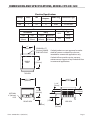
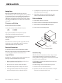
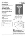
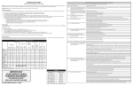
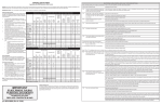
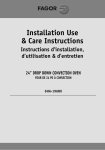
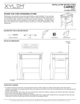
INSTALLATION AND
OPERATION MANUAL
GARLAND COUNTER-TOP
ELECTRIC OVENS
MODELS: CPO-ES-12H,
CPO-ED-12H, & CPO-ED-24H
FOR YOUR SAFETY:
DO NOT STORE OR USE GASOLINE
OR OTHER FLAMMABLE VAPORS OR
LIQUIDS IN THE VICINITY OF
THIS OR ANY OTHER
APPLIANCE
WARNING:
IMPROPER INSTALLATION, ADJUSTMENT,
ALTERATION, SERVICE OR MAINTENANCE
CAN CAUSE PROPERTY DAMAGE, INJURY,
OR DEATH. READ THE INSTALLATION,
OPERATING AND MAINTENANCE
INSTRUCTIONS THOROUGHLY
BEFORE INSTALLING OR
SERVICING THIS EQUIPMENT
PLEASE READ ALL SECTIONS OF THIS MANUAL
AND RETAIN FOR FUTURE REFERENCE.
THIS PRODUCT HAS BEEN CERTIFIED AS
COMMERCIAL COOKING EQUIPMENT AND
MUST BE INSTALLED BY PROFESSIONAL
PERSONNEL AS SPECIFIED.
INSTALLATION AND ELECTRICAL CONNECTION
MUST COMPLY WITH CURRENT CODES:
IN CANADA - THE CANADIAN ELECTRICAL
CODE PART 1 AND / OR LOCAL CODES.
IN USA – THE NATIONAL ELECTRICAL CODE
ANSI / NFPA – CURRENT EDITION.
ENSURE ELECTRICAL SUPPLY CONFORMS WITH
ELECTRICAL CHARACTERISTICS SHOWN ON
THE RATING PLATE.
Users are cautioned that maintenance and repairs must be performed by a Garland authorized service agent
using genuine Garland replacement parts. Garland will have no obligation with respect to any product that has been
improperly installed, adjusted, operated or not maintained in accordance with national and local codes or installation
instructions provided with the product, or any product that has its serial number defaced, obliterated or removed,
or which has been modified or repaired using unauthorized parts or by unauthorized service agents.
For a list of authorized service agents, please refer to the Garland web site at http://www.garland-group.com.
The information contained herein, (including design and parts specifications), may be superseded and is subject
to change without notice.
Part##1844061
1844061Rev.
Rev.11(08/09/10)
(08/09/10)
Part
© 2004 The Garland Group
Page 1
IMPORTANT INFORMATION
WARNING:
This product contains chemicals known to the state of california to cause cancer and/or birth defects
or other reproductive harm. Installation and servicing of this product could expose you to airborne
particles of glass wool/ceramic fibers. Inhalation of airborne particles of glass wool/ceramic fibers
is known to the state of California to cause cancer.
Page 2
Part # 1844061 Rev. 1 (08/09/10)
TABLE OF CONTENTS
IMPORTANT INFORMATION . . . . . . . . . . . . . . . . . . . . . . . . . . . . . . . . . . . . . . . . . 2
DIMENSIONS AND SPECIFICATIONS, MODEL CPO-ES-12H . . . . . . . . . . . . . 4
DIMENSIONS AND SPECIFICATIONS, MODEL CPO-ED-12H . . . . . . . . . . . . . 5
DIMENSIONS AND SPECIFICATIONS, MODEL CPO-ED-24H . . . . . . . . . . . . . 6
INSTALLATION . . . . . . . . . . . . . . . . . . . . . . . . . . . . . . . . . . . . . . . . . . . . . . . . . . . . . 7
Rating Plate. . . . . . . . . . . . . . . . . . . . . . . . . . . . . . . . . . . . . . . . . . . . . . . . . . . . . . . . . . . . . . . . . . . . . . 7
Clearances and Setting. . . . . . . . . . . . . . . . . . . . . . . . . . . . . . . . . . . . . . . . . . . . . . . . . . . . . . . . . . . 7
Electrical Connections. . . . . . . . . . . . . . . . . . . . . . . . . . . . . . . . . . . . . . . . . . . . . . . . . . . . . . . . . . . . 7
Leg Instillation. . . . . . . . . . . . . . . . . . . . . . . . . . . . . . . . . . . . . . . . . . . . . . . . . . . . . . . . . . . . . . . . . . . 7
Deck Installation. . . . . . . . . . . . . . . . . . . . . . . . . . . . . . . . . . . . . . . . . . . . . . . . . . . . . . . . . . . . . . . . . 7
Initial Start Up . . . . . . . . . . . . . . . . . . . . . . . . . . . . . . . . . . . . . . . . . . . . . . . . . . . . . . . . . . . . . . . . . . . 7
OPERATING INSTRUCTIONS . . . . . . . . . . . . . . . . . . . . . . . . . . . . . . . . . . . . . . . . . 8
General Baking . . . . . . . . . . . . . . . . . . . . . . . . . . . . . . . . . . . . . . . . . . . . . . . . . . . . . . . . . . . . . . . . . . 8
Baking Tips. . . . . . . . . . . . . . . . . . . . . . . . . . . . . . . . . . . . . . . . . . . . . . . . . . . . . . . . . . . . . . . . . . . . . . 8
Special Features . . . . . . . . . . . . . . . . . . . . . . . . . . . . . . . . . . . . . . . . . . . . . . . . . . . . . . . . . . . . . . . . . 8
CLEANING . . . . . . . . . . . . . . . . . . . . . . . . . . . . . . . . . . . . . . . . . . . . . . . . . . . . . . . . . 9
TROUBLE SHOOTING . . . . . . . . . . . . . . . . . . . . . . . . . . . . . . . . . . . . . . . . . . . . . . . 9
Part # 1844061 Rev. 1 (08/09/10)
Page 3
Electrical Specifications
Voltage
Phase
kW
Nominal
Amperes
NEMA Plug
Connection Type
120
1
1.8
15.0
5-20P
6’LineCord
208
1
2.85
13.7
6-20P
6’LineCord
240
1
2.85
11.9
6-15P
6’LineCord
Dimensions
Clearances
Interior
(hearth area)
Exterior
H
W
D
17-1/2”
(445mm)
22-1/2”
(572mm)
23-1/2”
(597mm)
18-1/4"
[464mm]
BAKING
AREA
W
D
Installation
Sides
18-1/4”
18-1/4”
1”
(464mm) (464mm) (25mm)
Entry
Rear
Crated
Uncrated
1”
(25mm)
32”
(813mm)
27-1/2”
(699mm)
Shipping
STANDARD 6 FT
[1829mm] POWER
CORD WITH PLUG
18-1/4"
[464mm]
Cu Ft
Weight Lb/Kg
8.2
127/58
Garlandproductsarenotapprovedorauthorizedforhomeorresidentialuse,butare
intendedforcommercialapplicationsonly.
Garlandwillnotprovideservice,warranty,
maintenanceorsupportofanykindother
thanincommercialapplications.
TOP VIEW
22-1/2"
[572mm]
6"
[152mm]
17-1/2"
[445mm]
OPTIONAL 4"
[102 mm] LEGS
FRONT VIEW
Page 4
Garland Commercial Ranges Ltd
4"
[102mm]
23-1/2"
[597mm]
7-3/4"
[197mm]
SIDE VIEW
9"
[229mm]
CPOES12H(08/09/10)
Part # 1844061 Rev. 1 (08/09/10)
Electric Counter Top Pizza Oven w/2 Hearths
DIMENSIONS AND SPECIFICATIONS, MODEL CPO-ES-12H
Electrical Specifications
Voltage
Phase
kW
Nominal
Amperes
NEMA Plug
Connection Type
208
1
3.6
17.3
6-30P
6’LineCord
240
1
3.6
15
6-20P
6’LineCord
Clearances
Installation
Shipping
Entry
Sides
Rear
Crated
Uncrated
1”
(25mm)
1”
(25mm)
32”
(813mm)
27-1/2”
(699mm)
21"
[533mm]
BAKING
AREA
STANDARD 6 FT
[1829mm] POWER
CORD WITH PLUG
21"
[533mm]
CuFt
10.3
Wt.
Lb/Kg
145/66
Garlandproductsarenotapprovedorauthorizedforhomeorresidentialuse,butare
intendedforcommercialapplicationsonly.
Garlandwillnotprovideservice,warranty,
maintenanceorsupportofanykindotherthan
incommercialapplications.
TOP VIEW
25-1/2"
[648mm]
26-3/4"
[679mm]
3-1/8"
[79mm]
6-7/8"
[175mm]
17-1/2"
[445mm]
OPTIONAL
4" [102mm]
LEGS
FRONT VIEW
Part # 1844061 Rev. 1 (08/09/10)
7"
[178mm]
4"
[102mm]
SIDE VIEW
9-1/4"
[235mm]
Form#CPOED12H(08/09/10)
Page 5
Electric Counter Top Pizza Oven w/2 Hearths
DIMENSIONS AND SPECIFICATIONS, MODEL CPO-ED-12H
Electrical Specifications
Voltage
Phase
kW
208
1
240
Nominal Amperes Per Line
NEMA Plug
Connection Type
—
6-50P
6’LineCord
30.0
—
6-50P
6’LineCord
30.0
17.3
17.3
—
TerminalBlock
26.0
16.3
16.3
—
TerminalBlock
L1
L2
L3
7.2
34.6
34.6
1
7.2
30.0
208
3
7.2
240
3
7.2
Clearances
Installation
Entry
Sides
Rear
Crated
Uncrated
1”
(25mm)
1”
(25mm)
32”
(813mm)
27-1/2”
(699mm)
21"
[533mm]
28-7/8"
[733mm]
Shipping
BAKING
AREA
STANDARD 6 FT
[1829mm] POWER
CORD WITH PLUG
(SGL-PHASE UNITS ONLY)
21"
[533mm}
6-50P
Cu Ft
Weight
Lb/Kg
18.8
293/233
Garlandproductsarenotapprovedor
authorizedforhomeorresidentialuse,
butareintendedforcommercialapplicationsonly.Garlandwillnotprovide
service,warranty,maintenanceorsupportofanykindotherthanincommercialapplications.
TOP VIEW
26-1/2"
[673mm]
9-1/4"
[235mm]
6-7/8"TYP
[175mm]
29"
[737mm]
OPTIONAL 4"
[102mm] LEGS
FRONT VIEW
Page 6
18-1/4"
[464mm]
4"
[102mm]
3-1/8"TYP
[79mm]
3-1/8"TYP
[79mm]
6-7/8"
[175mm]
SIDE VIEW
Form#CPOED24(08/09/10)
Part # 1844061 Rev. 1 (08/09/10)
Electric Counter Top Double Pizza Oven w/4 Hearths
DIMENSIONS AND SPECIFICATIONS, MODEL CPO-ED-24H
INSTALLATION
Rating Plate
When corresponding with the factory or your local
authorized factory service center regarding service problems
or replacement parts, be sure to refer to the particular unit
by the correct model number (including the prefix and
suffix letters and numbers) and the warranty serial number.
The rating plate affixed to the rear of the oven contains this
information.
Clearances and Setting
Minimum Clearance for Installation.
Combustible to Non-Combustible Wall Clearance:
Side:
1” (25 mm)
Rear:
1” (25 mm)
5. Carefully tilt oven up onto the legs and adjust the bottom
of the legs to make the unit level.
6. Slide baking deck into each shelf and secure with
stainless steel hearth trim. (See Deck Installation)
Deck Installation
A. Slide baking decks into each shelf.
B. Remove screw from mounting bracket left and right side.
C. Place stainless steel (deck hold down) in place.
D. Fasten screws to mounting bracket.
Proper placement of the oven will ensure operator
convenience and satisfactory performance.
NOTE: Adequate clearance must be provided for servicing
and proper operation.
Location
MOUNTING
SCREW
LOCATION
Due to the heat a counter-top oven may produce, it must
be placed on a non-combustible surface. Do not store
combustible materials on top of any oven.
DECK
Electrical Connections
DECK HOLD DOWN
An all pole disconnect must be provided by the installer.
Make sure electrical supply corresponds with that specified
on the rating plate located in the rear of the oven.
Leg Instillation
Initial Start Up
Optional legs – for shipping purposes the optional 4” (102
mm) legs are not mounted to any of the ovens.
After the electrical connections have been made, the oven
will need approximately 2 to 3 hours to burn off. Initial
heating of the oven may generate smoke or fumes and must
be done in a well-ventilated area.
1. After unpacking, remove legs, baking decks and any
other material from inside the oven.
CAUTION: Over-exposure to smoke or fumes may cause
nausea and dizziness.
2. Place the unit on a counter or other flat surface.
For initial heating of the oven, follow the steps below:
3. With sufficient help, tilt unit carefully onto its back.
A. Place the oven in a well-ventilated area.
4. Screw legs into the bottom of the unit using holes
provided and tighten with an adjustable wrench.
B. Open the door and remove any instructions or samples
that have been shipped with the unit.
Part # 1844061 Rev. 1 (08/09/10)
Page 7
INSTALLATION Continued
NOTE: Make sure the oven cavity is empty and the baking
decks are properly installed.
D. Close the oven door. Increase the temperature to 500°F
(260°C) for at least 1 1/2 hours.
C. With the oven door open, turn the temperature knob to
400°F (205°C) for 1 hour.
This procedure will dry out the insulation and deck material
and will help to insure the best baking results.
OPERATING INSTRUCTIONS
General Baking
Preheat the oven by setting the thermostat to the desired
temperature. When the thermostat light goes out and has
cycled three times, the oven is ready for use.
CPO-ED ovens have been designed to bake both fresh and
pre-baked products.
C. For fresh dough pizza, flour or corn meal on the peel will
prevent sticking and ease placement of the pizza on the
deck.
D. Increasing the bake temperature during heavy
production assists in maintaining temperature. After the
rush is over reduce the temperature to prevent burning.
CPO-ES ovens perform best with pre-baked product.
E. Heavily topped pizzas require longer bake times at lower
temperatures.
These ovens work well for toasting, melting cheese, baking
frozen entrees, roasting small meat items, etc.
F. Placing a screen under the pizza will allow the top to cook
without overcooking the bottom.
The temperature range on pizza baking is usually between
500°F (260°C) and 575ºF (300°C) depending on the individual
product.
G. Frequently scrape and brush off the decks to remove
burnt residue which can cause an off flavor to the
product. Residue build-up can slow bake times.
Fully defrost pizza crusts before baking. Allow the pizza to
bake until the cheese bubbles and the bottoms are brown.
H. Clean heavily soiled pizza decks by scraping down, brush
off, removing from oven, turning over and putting back.
This procedure will burn off the decks and should be
repeated every 6 months. Do not use water as this could
cause the decks to crack.
Do not keep the oven door open too long when loading
since heat will escape, resulting in slower baking.
When production requirements are low, keep the
temperature low to prevent the bottoms from burning.
As demand increases, temperature should be raised for faster
recovery.
Fresh dough generally requires slightly lower baking
temperature and longer bake time than defrosted pre-bake
crusts
Baking Tips
I. Using shiny pans or screens will produce products with
a light color to the bottom. We strongly suggest that all
pans and screens be seasoned before use.
Special Features
Timer – A mechanical timer is provided to give an audible
signal at the end of a pre-set time (up to 15 minutes).
NOTE: Timer does not control the oven.
A. Pizza crusts should be fully defrosted before baking.
B. Wet areas on the bottom of a pizza will cause them to
stick to the deck. Avoid spills.
Page 8
Part # 1844061 Rev. 1 (08/09/10)
CLEANING
Periodic cleaning is suggested to keep your oven in good
condition.
A. Turn the thermostat up to the highest setting and let the
oven run for 1/2 hour with the door closed.
NOTE: Always clean the oven only when it is cold. When
cleaning stainless steel, always wipe in the direction of the
grain.
B. Allow the oven to cool down.
From time to time the spillage should be scraped out. For
hard to clean spillage, the following is recommended:
NOTE: Do not use water to clean the decks, as this could
cause them to crack.
C. Brush the residue from the deck.
TROUBLE SHOOTING
The ovens are designed to be as trouble-free as possible.
Keeping the oven clean is all that is normally required. All
servicing should be performed only by a factory authorized
technician.
If the oven still does not operate, take the following steps:
However, if your oven stops operating, please check the
following:
B. Contact the factory, factory representative or an
authorized service agency.
A. Power supply cord is plugged into the supply receptacle.
A wiring diagram is provided on the back of the unit.
A. Disconnect the power supply to the unit by removing the
supply cord and/or turning of the main switch.
B. Power supply fuse/circuit has not tripped.
Part # 1844061 Rev. 1 (08/09/10)
Page 9
INSTRUCTIONS D’UTILISATION suite
I. L’utilisation de plats ou de grilles brillants permettra
d’obtenir des produits dont le fond sera clair. Nous
recommandons fortement d’apprêter les plats et grilles
avant de les utiliser.
Caractéristiques Spéciales
Minuterie – Une minuterie mécanique est prévue pour
donner un signal sonore à la fin d’un temps préréglé (jusqu’à
15 minutes).
NOTA : La minuterie ne commande pas le four.
NETTOYAGE
Il est suggéré d’effectuer un nettoyage périodique pour
maintenir le four en bon état.
NOTA : Toujours nettoyer le four quand il est froid
uniquement. Pour nettoyer l’acier inoxydable, toujours
frotter dans le sens du grain.
A. Régler le thermostat à la température la plus élevée et
laisser le four fonctionner pendant 1/2 heure avec la
porte fermée.
B. Laisser le four refroidir.
C. Brosser les résidus de la sole.
De temps en temps, il est nécessaire de gratter les
déversements. Dans le cas de produits difficiles à retirer, il est
recommandé de procéder comme suit :
NOTA : Ne pas utiliser d’eau pour nettoyer les sections du
four, car cela pourrait causer des fissures.
DÉPANNAGE
Les fours sont conçus pour causer le moins de problème
possible. Normalement, il suffit de maintenir le four propre.
Tout dépannage devra être effectué uniquement par un
technicien agréé par l’usine.
Cependant, si le four ne fonctionne plus, vérifier les points
suivants :
A. Le cordon d’alimentation électrique est branché dans la
prise d’alimentation.
Si le four ne fonctionne toujours pas, procéder comme suit :
A. Débrancher l’alimentation de l’appareil en retirant le
cordon d’alimentation ou en fermant l’interrupteur
principal.
B. Contacter l’usine, le représentant de l’usine ou une
entreprise de service agréée.
Un schéma de câblage du système est intégré au présent
manuel et se trouve également au dos de l’appareil.
B. Le fusible/disjoncteur d’alimentation n’est pas fondu/
déclenché.
Pièce nº 1844061 Rev. 1 (08/09/10)
Page 9
INSTALLATION Suite
Cette procédure permettra de sécher l’isolant et le matériau
des sections et assurera les meilleurs résultats de cuisson
possibles.
C. Avec la porte du four ouverte, tourner le bouton de
réglage de température à 400° F (205° C) pendant 1
heure.
D. Fermer la porte du four. Augmenter la température à 500°
F (260° C) pendant au moins 1 heure 1/2.
NOTA : S’assurer que l’intérieur du four est vide et que les
sections de cuissons sont correctement installées.
INSTRUCTIONS D’UTILISATION
A. Le croûtes à pizza devront être complètement
décongelées avant la cuisson.
Préchauffer le four en réglant le thermostat à la température
souhaitée. Quand le témoin du thermostat s’éteint après trois
cycles, le four est prêt à être utilisé.
Conseils De Cuisson Générale
Cuisson Générale
Les fours CPO-ED ont été conçus pour la cuisson des produits
frais et précuits.
Les fours CPO-ES fonctionnent mieux avec les produits
précuits.
Ces fours sont pratiques pour le brunissement, pour faire
fondre le fromage, pour cuire les plats congelés, pour faire
rôtir les petites pièces de viande, etc.
La gamme de température pour la cuisson des pizzas est
habituellement comprise entre 500° F (260° C) et 575° F (300°
C) en fonction des produits.
Décongeler complètement les pâtes à pizza avant la cuisson.
Laisser cuire la pizza jusqu’à ce que le fromage fasse des
bulles et que le fond soit brun.
Ne pas laisser trop longtemps la porte ouverte lors du
chargement du four, car la chaleur sortira, ce qui ralentira la
cuisson.
Quand les besoins en matière de production sont bas,
maintenir la température basse pour empêcher les fonds de
brûler.
Au fur et à mesure que la demande augmente, on devra
augmenter la température pour un réchauffement plus
rapide.
B. Les endroits humides sur le fond d’une pizza colleront sur
la sole. Éviter de renverser des produits liquides.
C. Pour les pizzas à pâte fraîche, mettre de la farine ou de la
semoule de maïs sur la pelle à enfourner pour l’empêcher
de coller et faciliter la mise en place de la pizza sur la sole.
D. Le fait d’augmenter la température de cuisson pendant
les périodes de production importante permet de
maintenir la température. Une fois la période de pointe
terminée, réduire la température pour empêcher les
produits de brûler.
E. Les pizzas très garnies ont besoin de temps de cuisson
plus longs à des températures plus basses.
F. En plaçant une grille sous la pizza, il est possible de cuire
le dessus sans trop cuire le dessous.
G. Gratter et brosser fréquemment les sections de cuisson
pour éliminer les résidus brûlés qui pourraient donner un
goût aux produits. L’accumulation de résidus peut ralentir
les temps de cuisson.
H. Pour nettoyer les sections à pizzas très sales, les gratter,
les brosser, les retirer du four, les retourner et les remettre
en place. Cette procédure calcinera les sections de
cuisson et devra être répétée tous les 6 mois. Ne pas
utiliser d’eau car cela causera des fissures dans les
sections.
La pâte fraîche a généralement besoin d’une température de
cuisson légèrement inférieure et d’un temps de cuisson plus
long que les croûtes précuites décongelées.
Page 8
Pièce nº 1844061 Rev. 1 (08/09/10)
INSTALLATION
Plaque Signalétique
Lors de toute correspondance avec l’usine ou le centre de
service d’usine local agréé concernant des problèmes de
service ou des pièces de rechange, bien faire référence à
cet équipement particulier en indiquant le bon numéro de
modèle (avec les lettres du préfixe et du suffixe ainsi que les
chiffres) et le numéro de série de la garantie. On peut trouver
ces informations sur la plaque signalétique fixée sur l’unité.
Dégagements Et Réglage
Dégagement minimal pour l’installation.
Dégagement des murs combustibles à incombustibles :
Côtés:
1 Po (25 mm)
Arrière:
1 Po (25 mm)
5. Remettre avec précaution l’appareil sur ses pieds et régler
le bas des pieds pour mettre l’appareil de niveau.
6. Glisser la section de cuisson dans chaque étagère et
fixer avec la garniture de sole en acier inoxydable. (voir
l’installation des sections)
Installation Des Sections
A. Glisser une section de cuisson sur chaque étagère.
B. Retirer les vis des supports de montage à gauche et à
droite.
C. Placer le blocage de section en acier inoxydable comme
illustré.
D. Remettre en place les vis des supports de montage
retirées à l’étape B.
Une installation correcte du four facilitera l’utilisation et
assurera des résultats satisfaisants.
NOTA : Un dégagement correct doit être prévu pour
l’utilisation et l’entretien.
Emplacement
En raison de la chaleur produite par ce four de plan de travail,
il doit être placé sur une surface incombustible. Ne jamais
conserver de matériaux inflammables au-dessus d’un four.
EMPLACEMENT
DES VIS
DE MONTAGE
Connexions Électriques
Un interrupteur à déconnexion de tous les pôles doit être
fourni par l’installateur.
Vérifier que l’alimentation électrique correspond à ce qui est
indiqué sur la plaque signalétique placée à l’arrière du four.
Installation Des Pieds.
Pieds en option - pour le transport, les pieds de 4 po
(100mm) en option ne sont pas montés sur les fours.
SECTION
BLOCAGE DE SECTION
Démarrage Initial
Pour le chauffage initial du four, suivre les étapesci-après :
3. En se faisant aider si nécessaire, basculer soigneusement
l’appareil sur le dos.
ATTENTION : Une surexposition aux fumées ou vapeurs
peut causer des nausées et des vertiges.
2. Placer l’appareil sur le plan de travail ou une autre
surface plane.
Une fois les connexions électriques effectuées, le four aura
besoin d’environ 2 à 3 heures de nettoyage. Le chauffage
initial du four peut créer des fumées ou des vapeurs et doit
être effectué dans un endroit bien ventilé.
1. Après le déballage, retirer les pieds, les sections de
cuisson et tout le reste du matériel de l’intérieur du four.
4. Visser les pieds dans le dessous de l’appareil en utilisant
les trous prévus à cet effet et serrer avec une clé à
molette.
A Placer le four dans un endroit bien ventilé.
B. Ouvrir la porte et retirer les instructions ou échantillons
expédiés avec l’appareil.
Pièce nº 1844061 Rev. 1 (08/09/10)
Page 7
DIMENSIONS ET SPÉCIFICATIONS, MODÈLE CPO-ED-24H
21"
[533mm]
28-7/8"
[733mm]
SECTEUR DE
TRAITEMENT
AU FOUR
STANDARD CORDON
DU SECTEUR
6 PI [1829mm]
AVEC LA PRISE
(UNITÉS MONOPHASÉ SEULEMENT)
21"
[533mm ]
6-50P
VUE DE DESSUS
26-1/2"
[673mm ]
9-1/4"
[235mm]
6-7/8" TYP
[175mm]
29"
[737mm ]
PIEDS DE
4 PO (102mm)
EN OPTION
18-1/4"
[464mm]
6-7/8"
[175mm]
VUE DE AVANT
4"
[102mm]
3-1/8" TYP
[79mm]
3-1/8" TYP
[79mm]
VUE DE CÔTÉ
Caractéristiques Électriques
3
240
3
208
1
240
1
208
Phase
Tension
kW
7.2
7.2
7.2
7.2
Ampérage Nominal Par Lignee
34.6
34.6
L2
L1
30.0
30.0
30.0
17.3
26.0
16.3
L3
----17.3
16.3
Prise NEMA
6-50P
6-50P
-----
Type De
Connexion
Cordon De 6 Pi
Cordon De 6 Pi
Bloc De Jonction
Bloc De Jonction
Dégagements
Installation
1 Po
(25mm)
1 Po
(25mm)
Arrière
Côtés
Entrée
En Caisse
32 Po
(813mm)
Déballé
27-1/2 Po
(699mm)
Page 6
Pièce nº 1844061 Rev. 1 (08/09/10)
DIMENSIONS ET SPÉCIFICATIONS, MODÈLE CPO-ED-12H
21"
[533mm]
SECTEUR DE
TRAITEMENT
AU FOUR
STANDARD CORDON
DU SECTEUR
6 PI [1829mm]
AVEC LA PRISE
21"
[533mm]
VUE DE DESSUS
25-1/2"
[648mm]
26-3/4"
[679mm]
3-1/8"
[79mm]
PIEDS DE
4 PO (102mm)
EN OPTION
6-7/8"
[175mm]
17-1/2"
[445mm ]
7"
[178mm]
VUE DE AVANT
4"
[102mm]
9-1/4"
[235mm]
VUE DE CÔTÉ
Caractéristiques Électriques
1
240
1
208
Phase
Tension
kW
6-30P
17.3
Prise NEMA
Intensité
Nominale
3.6
3.6
15
6-20P
Type De
Connexion
Cordon De 6 Pi
Cordon De 6 Pi
Dégagements
Installation
Entrée
1 Po
(25mm)
1 Po
(25mm)
Arrière
Côtés
En Caisse
32 Po
(813mm)
Déballé
27-1/2 Po
(699mm)
Pièce nº 1844061 Rev. 1 (08/09/10)
Page 5
DIMENSIONS ET SPÉCIFICATIONS, MODÈLE CPO-ES-12H
18-1/4"
[464mm]
SURFACE
DE CUISSON
STANDARD CORDON
DU SECTEUR
6 PI [1829mm]
AVEC LA PRISE
18-1/4"
[464mm]
VUE DE DESSUS
23-1/2"
[597mm]
22-1/2"
[572mm]
6"
[152mm]
17-1/2"
[445mm]
PIEDS DE
4 PO (102mm)
EN OPTION
7-3/4"
[197mm]
VUE DE AVANT
VUE DE CÔTÉ
4"
[102mm]
9"
[229mm]
Caractéristiques Électriques
1
240
1
208
1
120
Phase
Tension
kW
5-20P
15.0
Prise NEMA
Intensité
Nominale
1.8
2.85
13.7
2.85
11.9
Dimensions
L
P
6-20P
6-15P
Type De
Connexion
Cordon De 6 Pi
Cordon De 6 Pi
Cordon De 6 Pi
Dégagements
Intérieur
(Secteur De Foyer)
Extérieur
H
L
Installation
P
17-1/2 Po 22-1/2 Po 23-1/2 Po 18-1/4 Po
(445mm) (572mm) (597mm) (464mm)
Côtés
18-1/4 Po
(464mm)
1 Po
(25mm)
Pds
D’expédition
Entrée
Arrière
En Caisse
1 Po
(25mm)
32 Po
(813mm)
Page 4
Déballé
27-1/2 Po
(699mm)
127lbs
(58kg)
Pièce nº 1844061 Rev. 1 (08/09/10)
TABLE DES MATIÈRES
INFORMATIONS IMPORTANTES . . . . . . . . . . . . . . . . . . . . . . . . . . . . . . . . . . . . . . 2
DIMENSIONS ET SPÉCIFICATIONS, MODÈLE CPO-ES-12H . . . . . . . . . . . . . . . 4
DIMENSIONS ET SPÉCIFICATIONS, MODÈLE CPO-ED-12H. . . . . . . . . . . . . . . 5
DIMENSIONS ET SPÉCIFICATIONS, MODÈLE CPO-ED-24H . . . . . . . . . . . . . . 6
INSTALLATION . . . . . . . . . . . . . . . . . . . . . . . . . . . . . . . . . . . . . . . . . . . . . . . . . . . . . . 7
Plaque Signalétique . . . . . . . . . . . . . . . . . . . . . . . . . . . . . . . . . . . . . . . . . . . . . . . . . . . . . . . . . . . . . .7
Dégagements Et Réglage . . . . . . . . . . . . . . . . . . . . . . . . . . . . . . . . . . . . . . . . . . . . . . . . . . . . . . . .7
Connexions Électriques . . . . . . . . . . . . . . . . . . . . . . . . . . . . . . . . . . . . . . . . . . . . . . . . . . . . . . . . . .7
Installation Des Pieds. . . . . . . . . . . . . . . . . . . . . . . . . . . . . . . . . . . . . . . . . . . . . . . . . . . . . . . . . . . . .7
Installation Des Sections . . . . . . . . . . . . . . . . . . . . . . . . . . . . . . . . . . . . . . . . . . . . . . . . . . . . . . . . .7
Démarrage Initial . . . . . . . . . . . . . . . . . . . . . . . . . . . . . . . . . . . . . . . . . . . . . . . . . . . . . . . . . . . . . . . .7
INSTRUCTIONS D’UTILISATION. . . . . . . . . . . . . . . . . . . . . . . . . . . . . . . . . . . . . . . 8
Cuisson Générale . . . . . . . . . . . . . . . . . . . . . . . . . . . . . . . . . . . . . . . . . . . . . . . . . . . . . . . . . . . . . . . .8
Conseils De Cuisson Générale . . . . . . . . . . . . . . . . . . . . . . . . . . . . . . . . . . . . . . . . . . . . . . . . . . . .8
Caractéristiques Spéciales . . . . . . . . . . . . . . . . . . . . . . . . . . . . . . . . . . . . . . . . . . . . . . . . . . . . . . . .9
NETTOYAGE . . . . . . . . . . . . . . . . . . . . . . . . . . . . . . . . . . . . . . . . . . . . . . . . . . . . . . . . 9
DÉPANNAGE . . . . . . . . . . . . . . . . . . . . . . . . . . . . . . . . . . . . . . . . . . . . . . . . . . . . . . . 9
Pièce nº 1844061 Rev. 1 (08/09/10)
Page 3
INFORMATIONS IMPORTANTES
AVERTISSEMENT
Ce produit contient des produits chimiques reconnus par l’état de Californie comme causant
le cancer et/ou des malformations congénitales ou d’autres problèmes de reproduction.
L’installation et l’entretien de ce produit peut vous exposer aux poussières de laine de
verre/fibres céramiques. L’inhalation de ces particules de laine de verre ou de fibres céramiques
est reconnue par l’état de Californie comme causant le cancer.
Page 2
Pièce nº 1844061 Rev. 1 (08/09/10)
MANUEL D’UTILISATION ET
D’INSTALLATION
FOURS ÉLECTRIQUES
DE PLAN DE TRAVAIL
MODÈLES : CPO-ES-12H,
CPO-ED-12H, ET CPO-ED-24H
POUR VOTRE SÉCURIT:
NE PAS STOCKER NI UTILISER D’ESSENCE
OU D’AUTRES VAPEURS OU LIQUIDES
INFLAMMABLES À PROXIMITÉ DE CET
APPAREIL OU DE TOUT AUTRE APPAREIL
AVERTISSEMENT
UNE INSTALLATION, DES RÉGLAGES, DES
MODIFICATIONS, DES RÉPARATIONS OU UN
ENTRETIEN MAL FAITS PEUVENT CAUSER
DES DOMMAGES MATÉRIELS, DES BLESSURES OU LA MORT. LIRE SOIGNEUSEMENT LES INSTRUCTIONS D’INSTALLATION,
D’UTILISATION ET D’ENTRETIEN
AVANT D’INSTALLER OU DE RÉPARER
L’ÉQUIPEMENT.
LIRE TOUTES LES SECTIONS DU PRÉSENT
MANUEL ET LE CONSERVER POUR S’Y REPORTER
ULTÉRIEUREMENT.
CE PRODUIT A ÉTÉ HOMOLOGUÉ EN TANT
QU’ÉQUIPEMENT PROFESSIONNEL DE CUISSON
ET DOIT ÊTRE INSTALLÉ PAR DU PERSONNEL
PROFESSIONNEL TEL QUE SPÉCIFIÉ.
L’INSTALLATION ET LES CONNEXIONS
DEVRONT ÊTRE CONFORMES AUX CODES EN
VIGUEUR: AU CANADA – LE CODE CANADIEN
DE L’ÉLECTRICITÉ, PARTIE 1 ET/OU LES CODES
LOCAUX. AUX É.-U. – LE NATIONAL ELECTRICAL
CODE ANSI / NFPA – ÉDITION EN VIGUEUR.
VÉRIFIER QUE L’ALIMENTATION ÉLECTRIQUE
EST CONFORME AUX CARACTÉRISTIQUES
ÉLECTRIQUES FIGURANT SUR LA PLAQUE
SIGNALÉTIQUE.
L’attention des utilisateurs est attirée sur le fait que l’entretien et les réparations doivent être effectués par un agent
d’entretien autorisé par Garland utilisant des pièces de rechange d’origine Garland. Garland n’aura aucune obligation
en ce qui concerne n’importe quel produit mal installé, réglé, utilisé ou qui n’aurait pas été entretenu conformément aux
codes nationaux et locaux ou aux instructions d’installation fournies avec le produit ou n’importe quel produit dont le
numéro de série aurait été mutilé, oblitéré ou supprimé ou qui aurait été modifié ou réparé avec des pièces non autorisées
ou par des agents d’entretien non autorisés. Pour obtenir la liste des agents de service autorisés, consulter le site web
de Garland à : http://www.garland-group.com. Les renseignements contenus dans le présent document (y compris la
conception et les spécifications des pièces) peuvent être remplacés ou modifiés sans préavis.
Piècenºn°1844061
1844061Rev.
Rev.11(08/09/10)
(08/09/10)
Pièce
© 2004 The Garland Group
Page 1