1
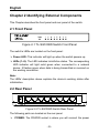
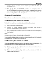
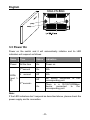
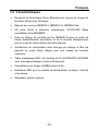
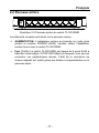
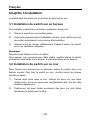
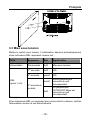
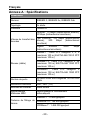
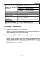
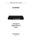
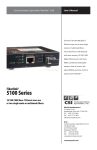
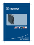
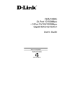
Content English……………………………………………………… 1 Français………………………………….…………………11 English COPYRIGHT & TRADEMARKS Specifications are subject to change without notice. is a registered trademark of TP-LINK TECHNOLOGIES CO., LTD. Other brands and product names are trademarks or registered trademarks of their respective holders. No part of the specifications may be reproduced in any form or by any means or used to make any derivative such as translation, transformation, or adaptation without permission from TP-LINK TECHNOLOGIES CO., LTD. Copyright © 2014 TP-LINK TECHNOLOGIES CO., LTD. All rights reserved. http://www.tp-link.com FCC STATEMENT This equipment has been tested and found to comply with the limits for a Class B digital device, pursuant to part 15 of the FCC Rules. These limits are designed to provide reasonable protection against harmful interference in a residential installation. This equipment generates, uses and can radiate radio frequency energy and, if not installed and used in accordance with the instructions, may cause harmful interference to radio communications. However, there is no guarantee that interference will not occur in a particular installation. If this equipment does cause harmful interference to radio or television reception, which can be determined by turning the equipment off and on, the user is encouraged to try to correct the interference by one or more of the following measures: Reorient or relocate the receiving antenna. Increase the separation between the equipment and receiver. -1- English Connect the equipment into an outlet on a circuit different from that to which the receiver is connected. Consult the dealer or an experienced radio/ TV technician for help. This device complies with part 15 of the FCC Rules. Operation is subject to the following two conditions: 1) This device may not cause harmful interference. 2) This device must accept any interference received, including interference that may cause undesired operation. Any changes or modifications not expressly approved by the party responsible for compliance could void the user’s authority to operate the equipment. CE Mark Warning This is a class B product. In a domestic environment, this product may cause radio interference, in which case the user may be required to take adequate measures. Safety Notices Cautions: Do not use this product near water, for example, in a wet basement or near a swimming pool. Avoid using this product during an electrical storm. There may be a remote risk of electric shock from lightning. -2- English Package Contents The following items should be found in your package: One TL-SG1005D/TL-SG1008D switch One Power Adapter This User Guide Note: The wall-mounting screws are not provided with our product. Please contact your distributor if any of the listed items are damaged or missing. Convention The switch or TL-SG1005D/TL-SG1008D mentioned in this User Guide stands for TL-SG1005D/TL-SG1008D 5/8-port Gigabit Desktop Switch without any explanation. Note: The two devices of TL-SG1005D and TL-SG1008D are sharing this User Guide. For simplicity, we will take TL-SG1008D for example throughout this Guide. The differences between them are: TL-SG1005D switch with 5 10/100/1000Mbps Auto-Negotiation RJ45 ports. TL-SG1008D switch with 8 10/100/1000Mbps Auto-Negotiation RJ45 ports. -3- English Chapter 1 Introduction of the Product Thank you for choosing the TL-SG1005D/TL-SG1008D 5/8-port Gigabit Desktop Switch. 1.1 Overview of the Product Powered by the Gigabit Ethernet Technology, TL-SG1005D/ TLSG1008D Gigabit Desktop Switch provides the seamless network connection, which can speed up your old network to 1000Mbps, ensuring the graphics, CGI, CAD, or multimedia files and other applications with bandwidth-intensive files transferred across the network almost instantly. The non-blocking switching architecture adopted in the TL-SG1005D/TLSG1008D switch greatly improves network response times as well as significantly speed up the traffic between subnets by forwarding and filtering packets at full wire-speed for maximum throughput. The TL-SG1005D/TL-SG1008D switch is plug-and-play. In addition, the Auto-MDI/MDIX cable detection on all ports eliminates the demand of crossover cable or Uplink port. Each port can be used as general ports or Uplink ports, and any port can be simply plugged into a server, a hub, a router, a switch or a PC, using the straight cable or crossover cable. Diagnostic LEDs which display link status and activity, allowing you to quickly detect and correct problems on the network. The TL-SG1005D/TL-SG1008D switch adopts Green Ethernet technology, supports power saving features. The switch automatically powers down the ports that have no link or are connected to the computers which have been shut down, budgets power output for different Ethernet cable lengths. 1.2 Features Supports Green Ethernet technology to implement power saving features Complies with IEEE802.3, IEEE802.3u, IEEE802.3ab standards -4- English 5/8 10/100/1000Mbps Auto-Sensing RJ45 ports supporting AutoMDI/MDIX Supports IEEE802.3x flow control for Full-duplex Mode and backpressure for Half-duplex Mode Non-blocking switching architecture that forwards and filters packets at full wire-speed for maximum throughput 4K entry MAC address table of TL-SG1005D/TL-SG1008D with auto-learning and auto-aging Supports for Jumbo frames of up to 9KB LED indicators for monitoring power, link, speed and activity External power adapter supply -5- English Chapter 2 Identifying External Components This Chapter describes the front panel and rear panel of the switch. 2.1 Front Panel Figure 2-1 TL-SG1008D Switch Front Panel The switch’s LEDs are located on the front panel: Power LED: This indicator will light up when the switch powers up. LEDs (1~8): The LED indicates Link/Active status. The corresponding LED indicator will light solid green when connected to a network device. It flashes green when data is being transmitted or received on the working connection. Note: The LEDs’ description above explains the device’s working status after initialization. 2.2 Rear Panel Figure 2-2 TL-SG1008D Switch Rear Panel The following parts are located on the rear panel. POWER: The POWER socket is where you will connect the power -6- English adapter. Please use the power adapter provided with this TLSG1008D switch. Port (1-8): The TL-SG1008D switch is equipped with 8 10/100/1000Mbps Auto-Sensing RJ45 ports where you will connect your network devices. The working status can be indicated by the corresponding LEDs on the front panel. Chapter 3 Installation The switch can be either located on a desktop or mounted on a wall. 3.1 Mounting the Switch on a Desk To locate the switch on a desktop, please follow these steps: 1) Place the switch on a flat desk. 2) Inspect the Power Adapter carefully and make sure that it is properly connected to a power source. 3) Ensure adequate ventilation space around the switch for dissipating heat and air. Note: Please avoid any heavy thing placed on the switch. To ensure the stable cable connection, please keep the switch horizontal on the desktop, with white cover facing up. 3.2 Mounting the Switch on a Wall There are two wall-mounting slots on the bottom panel of the switch. To mount the switch on a wall, please follow the steps below. 1) Drill two holes into the wall. Insert a screw into each hole and leave a part of its head exposed. 2) Place the two wall-mounting slots over the screws and slide the switch down to fasten it. -7- English 3.3 Power On Power on the switch and it will automatically initialize and its LED indicators will respond as follows: Name Time Status Indication Power All the time On Power on st On N/A nd Off N/A Off No device connected corresponding port. On There is a 10/100/1000Mbps device connected to the corresponding port. 1 second LEDs (port 18) 2 second rd 3 second~ to the Note: If the LED indicators don’t respond as described above, please check the power supply and its connection. -8- English Appendix A: Specifications General Standards IEEE802.3, IEEE802.3u, IEEE802.3ab Topology Star Protocol CSMA/CD Ethernet: 10Mbps (Half Duplex), 20Mbps (Full Duplex) Data Transfer Rate Fast Ethernet: 100Mbps (Half Duplex), 200Mbps (Full Duplex) Gigabit Ethernet: 2000Mbps (Full Duplex) 10Base-T: UTP category 3, 4, 5 cable (maximum 100m) EIA/TIA-568 100Ω STP (maximum 100m) Network Media(Cable) 100Base-TX: UTP category 5, 5e cable (maximum 100m) EIA/TIA-568 100Ω STP (maximum 100m) 1000Base-T: UTP category 5 cable (maximum 100m) EIA/TIA-568 100Ω STP (maximum 100m) Number of Ports 5/8 10/100/1000Mbps RJ45 ports LED indicators Power, LEDs (1-8) Transfer Method Store-and-Forward MAC Address Learning Auto-Negotiation Automatically learning, automatically aging 10Base-T: 14880pps/Port Frame Filter Rate 100Base-Tx: 148800pps/Port 1000Base-T: 1488000pps/Port -9- English 10Base-T: 14880pps/Port Frame Forward Rate 100Base-Tx: 148800pps/Port 1000Base-T: 1488000pps/Port Environmental and Physical Operating Temperature 0 ~40℃ (32 ~104℉) Storage Temperature -40 ~70℃ (-40 ~158℉) Operating Humidity 10%~90% non-condensing Storage Humidity 5%~90% non-condensing Appendix B: Troubleshooting 1. The Power LED is not lit Check to see if the AC power cord is connected to the switch properly, and make sure the power source is ON. 2. The Link/Act LED is not lit when a device is connected to the corresponding port Check to see if the cable connectors are firmly plugged into the switch and the device, and verify the connected device is turned on and working well. Make sure the cable is not longer than 100 meters (328 feet). - 10 - Français AVIS SUR LES DROITS D'AUTEUR Les caractéristiques et spécifications peuvent être modifiées sans est une marque commerciale déposée par préavis. TP-LINK TECHNOLOGIES CO., LTD. Toutes les marques commerciales et déposées sont la propriété de leurs détenteurs respectifs. Ce document ne peut être copié, photocopié, reproduit, traduit ou enregistré sur aucun support électronique ou informatique, dans son intégralité ou en partie, sans l'accord écrit préalable de TP-LINK TECHNOLOGIES CO., LTD. Copyright © 2014 TP-LINK TECHNOLOGIES CO., LTD. Tous droits réservés. http://www.tp-link.com DÉCLARATION DE LA FCC Cet appareil a été testé et déclaré conforme aux limites des appareils numériques de Classe B, selon la section 15 des règlements de la FCC (Federal Communication Commission). Ces limites sont conçues pour assurer une protection raisonnable contre un brouillage préjudiciable lorsque l'appareil est utilisé dans un milieu résidentiel. L'appareil génère, utilise et peut diffuser de l'énergie sur les fréquences radio et, s'il n'est pas installé et utilisé conformément au mode d'emploi, il peut brouiller les communications radio. Il n'y a aucune garantie qu'un brouillage ne se produira pas dans un milieu particulier. Si cet appareil brouille les communications radio ou télévision, comme cela peut être vérifié en éteignant puis en allumant l'appareil, l'utilisateur peut tenter de corriger toute interférence en essayant une ou plusieurs des méthodes suivantes : Réorienter l'antenne réceptrice ou la placer à un autre endroit ; Éloigner davantage l'appareil du récepteur ; - 11 - Français Brancher l'appareil sur une autre prise de courant ou un circuit électrique différent de celui auquel le récepteur est connecté ; Pour toute aide, consulter le distributeur ou un technicien expérimenté radio/TV. Cet appareil est conforme à la section 15 des règlements de la FCC. Son utilisation est soumise aux deux conditions suivantes : 3) Cet appareil ne doit pas provoquer de brouillage préjudiciable. 4) Cet appareil doit absorber toute interférence réceptionnée, même si cela provoque des effets indésirables sur son fonctionnement. Toute modification non autorisée par les autorités responsables de la conformité peut entraîner la révocation du droit d'utilisation de ce produit. Avertissement de la marque CE Ceci est un appareil de classe B. Dans un environnement domestique, cet appareil peut créer des interférences radio, auquel cas l'utilisateur devra prendre les dispositions nécessaires. Notices de sécurité Attention : N'utilisez pas ce produit à proximité de l'eau (cave humide ou près d'une piscine). N'utilisez pas ce produit pendant un orage. Il se peut que les éclairs causent un choc électrique. - 12 - Français Contenu de l'emballage L'emballage doit contenir les éléments suivants : Un switch TL-SG1005D/TL-SG1008D Un adaptateur secteur Ce manuel utilisateur Remarque : Les vis de fixation au mur ne sont pas fournies avec le produit. Veuillez contacter votre distributeur si un des éléments de cette liste était manquant ou endommagé. Convention Lorsqu'il est fait référence au switch ou TL-SG1005D/TL-SG1008D dans ce manuel d'utilisation, il est toujours question du switch de bureau 5/8 ports Gigabit TL-SG1005D/TL-SG1008D, sauf mention contraire. Remarque : Les deux périphériques TL-SG1005D et TL-SG1008D partagent le même manuel d'utilisation. Par souci de simplicité, nous utiliserons toujours le TL-SG1008D comme exemple. Différence entre les deux périphériques : le switch TL-SG1005D dispose de 5 ports RJ45 auto-négociés 10/100/1000 Mbps. le switch TL-SG1008D dispose de 8 ports RJ45 auto-négociés 10/100/1000 Mbps. - 13 - Français Chapitre 1 Présentation du produit Nous vous remercions d'avoir choisi le switch de bureau 5/8 ports Gigabit TL-SG1005D/TL-SG1008D. 1.1 Aperçu du produit Grâce à la technologie Ethernet Gigabit, le switch de bureau Gigabit TLSG1005D/ TL-SG1008D vous assure une continuité de connexion et peut transformer votre ancien réseau en un réseau 1 000 Mbps. Le transfert de fichiers graphiques, CGI, CAD ou multimédia et autres applications gourmandes en bande passante se fait instantanément ! L'architecture de commutation sans blocage du TL-SG1005D/TLSG1008D redirige et filtre les paquets en mode filaire intégral pour une vitesse de transfert maximale ; le temps de réponse du réseau et la vitesse de trafic entre les sous-réseaux sont ainsi significativement améliorés. Le switch TL-SG1005D/TL-SG1008D dispose de la conception plug-andplay. En outre, la fonction de détection de câble Auto-MDI/MDIX sur tous les ports permet de s'affranchir des câbles croisés et des ports Uplink. Chaque port peut être utilisé comme port général ou port Uplink et peut être branché à un serveur, un concentrateur, un routeur, un switch ou un ordinateur via un câble croisé ou direct. Les DEL de diagnostic indiquent l'état de liaison et d'activité afin de détecter rapidement les problèmes sur le réseau et de les corriger. Le switch TL-SG1005D/TL-SG1008D utilise la technologie Green Ethernet, compatible avec des fonctions d'économie d'énergie. Le switch éteint automatiquement les ports si aucune liaison n'est détectée ou si l'ordinateur connecté au port est lui-même éteint et gère les puissances de sortie en fonction de la longueur des câbles Ethernet. - 14 - Français 1.2 Caractéristiques Équipé de la technologie Green Ethernet pour la prise en charge de fonctions d'économie d'énergie. Répond aux normes IEEE802.3, IEEE802.3u, IEEE802.3ab 5/8 ports RJ45 à détection automatique 10/100/1000 Mbps compatibles Auto-MDI/MDIX Prise en charge du contrôle de flux IEEE802.3x pour le mode de liaison bidirectionnelle simultanée et de la fonction Backpressure pour le mode de liaison bidirectionnelle alternée Architecture de commutation sans blocage qui redirige et filtre les paquets en mode filaire intégral pour une vitesse de transfert maximale. Table d'adressage MAC 4 K d'entrée du TL-SG1005D/TL-SG1008D avec auto-apprentissage et auto-vieillissement Compatible avec trames JUMBO jusqu'à 9 Ko Indicateurs DEL pour le contrôle de l'alimentation, la liaison, l'activité et la vitesse Adaptateur secteur externe - 15 - Français Chapitre 2 Identification des composants externes Ce chapitre décrit les panneaux avant et arrière du switch. 2.1 Panneau avant Illustration 2-1 Panneau avant du switch TL-SG1008D Les DEL du switch se situent sur le panneau avant: DEL alimentation : Cet indicateur s'allume lorsque le switch est mis sous tension. DEL (1 à 8) : Les diodes indiquent l'état de liaison (connexion active/transfert de données en cours). Si l'indicateur lumineux correspondant présente une lumière verte fixe, le périphérique est connecté au réseau. Si l'indicateur lumineux correspondant présente une lumière verte clignotante, des données sont transmises ou reçues via la connexion. Remarque : Les DEL vous indiquent l'état de la connexion du périphérique après initialisation. - 16 - Français 2.2 Panneau arrière Illustration 2-2 Panneau arrière du switch TL-SG1008D Les éléments suivants sont situés sur le panneau arrière. ALIMENTATION : L'adaptateur secteur se branche sur cette prise portant la mention POWER (ALIM). Veuillez utiliser l'adaptateur secteur fourni avec le switch TL-SG1008D. Port (1 à 8) : Le switch TL-SG1008D est équipé de 8 ports RJ45 à détection automatique 10/100/1000 Mbps sur lesquels vous pouvez connecter vos périphériques réseau. L'état de la connexion de chaque appareil est visible grâce aux diodes correspondantes sur le panneau avant. - 17 - Français Chapitre 3 Installation Le switch peut être placé sur un bureau ou bien fixé au mur. 3.1 Installation du switch sur un bureau Pour installer le switch sur un bureau, procédez comme suit : 1) Placez le switch sur une surface plane. 2) Inspectez soigneusement l'adaptateur secteur, puis vérifiez qu'il est raccordé correctement à une source d'alimentation. 3) Assurez-vous de laisser suffisamment d'espace autour du switch pour une ventilation adéquate. Remarque : Ne placez pas d'objet lourd sur le switch. Pour assurer une connexion par câble stable, veuillez laisser le switch en position horizontale sur le bureau, le panneau blanc sur le dessus. 3.2 Installation du switch sur un mur Deux fentes sont prévues sur le panneau arrière du switch pour une fixation murale. Pour fixer le switch au mur, veuillez suivre les étapes décrites ci-après. 1) Percez deux trous dans le mur. Insérez les deux vis, une dans chaque trou, et ne les vissez pas complètement afin que leur tête dépasse légèrement. 2) Positionnez les deux fentes au-dessus des deux vis, puis faites descendre le switch pour le fixer. - 18 - Français 3.3 Mise sous tension Mettez le switch sous tension. L'initialisation démarre automatiquement et les indicateurs DEL répondent comme suit : Nom Séquence État Signification Alimentation Permanente Actif Mise sous tension re Actif N/A e Inactif N/A Inactif Aucun périphérique connecté au port correspondant. Actif Un périphérique 10/100/1000 Mbps est connecté au port correspondant. 1 seconde 2 seconde DEL (ports 1 à 8) 3e seconde et au-delà Remarque : Si les indicateurs DEL ne répondent pas comme décrit ci-dessus, vérifiez l'alimentation secteur et ses branchements. - 19 - Français Annexe A : Spécifications Généralités Normes IEEE802.3, IEEE802.3u, IEEE802.3ab Topologie En étoile Protocole CSMA/CD Ethernet : 10 Mbps (bidirectionnel alterné), 20 Mbps (bidirectionnel simultané) Vitesse de transfert des Fast Ethernet : 100 Mbps (bidirectionnel alterné), 200 Mbps (bidirectionnel données simultané) Gigabit Ethernet : (bidirectionnel simultané) 2000 Mbps 10Base-T : Câble UTP catégorie 3, 4, 5 (maximum 100 m) EIA/TIA-568 100 Ω STP (maximum 100 m) Réseau (câble) 100Base-TX : Câble UTP catégorie 5, 5e (maximum 100 m) EIA/TIA-568 100Ω STP (maximum 100 m) 1000Base-T : Câble UTP catégorie 5 (maximum 100 m) EIA/TIA-568 100Ω STP (maximum 100 m) Nombre de ports 5/8 ports RJ45 auto-négociés 10/100/1000 Mbps Indicateurs lumineux Alim., DEL (1-8) Méthode de transfert Mode différé Apprentissage d'adresse MAC Apprentissage et vieillissement automatiques 10BASE-T : 14 880 pps/port Cadence de filtrage de 100BASE-TX : 148 800 pps/port trames 1000Base-T : 1 488 000 pps/port - 20 - Français 10BASE-T : 14 880 pps/port Cadence de redirection 100BASE-TX : 148 800 pps/port de trames 1000Base-T : 1 488 000 pps/port Propriétés physiques et environnementales Température de fonctionnement Température de stockage Humidité de fonctionnement Humidité de stockage 0 ~40℃ (32 ~104℉) -40 ~70℃ (-40 ~158℉) 10 % ~90 %, sans condensation 5 % ~90 %, sans condensation Annexe B : Dépannage 1. La diode d'alimentation ne s'allume pas. Vérifiez que le cordon d'alimentation est correctement branché au switch et assurez-vous que le courant passe. 2. La diode d'état de liaison ne s'allume pas lorsqu'un périphérique est connecté sur le port correspondant. Vérifiez que les connecteurs du câble sont correctement branchés dans le périphérique et le switch, puis que le périphérique est bien branché et fonctionne convenablement. Assurez-vous que le câble ne dépasse pas les 100 mètres. - 21 -