1
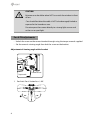
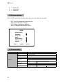
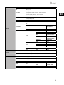
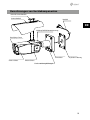
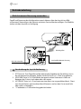
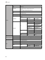
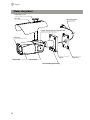
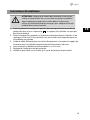
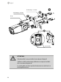
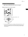
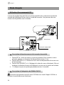
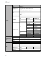
EN
DE
FR
Quick Installation Guide
1/3”
HD-TVI
Camera,
Day&Night,
1920x1080,
WDR, 10x AF Zoom, Infrared,
12/24V
TVB-2080Z10IR
Table of content
Parts supplied ................................................................................................................5
Part names ......................................................................................................................6
Installation instructions ................................................................................................7
Pan & Tilt adjustments......................................................................................................................................................8
Power supply connections..............................................................................................................................................9
Operating instructions ................................................................................................11
Using OSD controller..................................................................................................................................................... 11
Description of the joystick operation........................................................................................................ 11
Description of the ZOOM&FOCUS adjustment ..................................................................................... 11
OSD menu startup.......................................................................................................................................................... 12
OSD menu table.............................................................................................................................................................. 12
Further information .....................................................................................................14
2
Safety instructions
General safety instructions
• Before switching on and operating the system, first read this safety advice and the operating instructions.
• Keep the operating instructions in a safe place for later use.
• Installation, commissioning and maintenance of the system may only be carried out by authorised
individuals and in accordance with the installation instructions - ensuring that all applicable standards and
guidelines are followed.
• Protect the devices from water penetration and humidity, since these can cause lasting damage.
• Should moisture nevertheless enter the system, under no circumstance switch on the devices under these
conditions, instead send them for examination to an authorised specialist workshop.
• The system must never be used outside of the technical specifications, since this can destroy it.
• The device must be protected from excesses of heat, dust, humidity and vibration.
• When separating the system from the voltage supply, only ever use the plug to pull out the cable. Never
pull directly on the cable itself.
• Lay the connecting cables carefully and check that they are not mechanically stressed, kinked or damaged
and that no humidity can penetrate into them.
• In the event of a malfunction, please inform your supplier.
• Maintenance and repairs may only be carried out by authorised specialist personnel.
• The system must be isolated from the power supply before opening the housing.
• The device may only be opened by qualified service personnel. Unauthorised access invalidates any
warranty claim.
• Connection cables should always be exchanged through Videor E. Hartig GmbH.
• Use only original spare parts and accessories from Videor E. Hartig GmbH.
• The housing should only be cleaned using a mild domestic cleaning agent. Never use solvents or petrol as
these can permanently damage the surface.
• During installation, it is essential to ensure that the seals provided are correctly installed and that they are
not displaced during installation. Damaged seals must not be installed and will invalidate any warranty.
• The installer is responsible for the maintenance of the enclosure as per the technical data, e.g. by sealing
the cable outlets with silicone.
• Wire end ferrules should be used when shortening the flexible connection cables.
• The devices may only be operated in the temperature range indicated in the data sheet and within the
defined air humidity range.
Product - Specific Safety Instructions
• The camera may never be pointed directly at the Sun with the aperture open (this will destroy the sensor).
• It is unavoidable that during manufacture and to a certain extent during later use, humidity will be present
in the ambient air within the device’s housing. In the event of large temperature fluctuations, this humidity
may condense inside the housing.
• To avoid this condensation inside the very tightly sealed housing, the manufacturer has inserted silica gel
sachets in the housing of the various camera types.
• It is however a physical given, that these silica gel bags will reach saturation after a certain amount of time.
They should therefore be replaced with new silica gel sachets.
• During installation, it is essential to ensure that the seals provided are correctly installed and that they are
not displaced during installation. Damaged seals must not be installed and will invalidate any warranty.
• A multipolar, easily accessible isolation device should be installed in the proximity of the IR Spotlight, in
order to disconnect the device from the power supply for service work.
• The earth connection must be made according to the low impedance requirement of DIN VDE 0100.
• Subsequent painting of the equipment surface can impair the function.
• Any warranty claim is invalidated by subsequent painting.
• A safety margin of > 1m from the spotlight must be maintained when viewing directly into the IR Spotlight
in a darkened environment.
• Do not look directly at invisible LED radiation using optical instruments (e.g. a reading glass, magnifying
glass or microscope), since this can endanger the eyes, LED Class 1M.
• Operation of the IR spotlight with a defective cover or during repair is prohibited.
3
EN
Class A device note
This is a Class A device. This device can cause malfunctions in the living area; in such an event, the operator may
need to take appropriate measures to compensate for these.
WEEE (Waste Electronical & Electronic Equipment)
Correct Disposal of This Product (Applicable in the European Union and other European countries with separate
collection systems).
This marking shown on the product or its literature, indicates that it should not be disposed with
other household wastes at the end of its working life. To prevent possible harm to the environment
or human health from uncontrolled waste disposal, please separate this from other types of wastes
and recycle it responsibly to promote the sustainable reuse of material resources. Household users
should contact either the retailer where they purchased this product, or their local government
office, for details of where and how they can take this item for environmentally safe recycling.
Business users should contact their supplier and check the terms and conditions of the purchase
contract. This product should not be mixed with other commercial wastes for disposal.
Graphical symbols
Please pay attention to the safety instructions, and carefully read through this instruction guide before initial
operation.
Important points of warning are marked with a caution symbol.
i
4
Important points of advice are marked with a notice symbol.
Parts supplied
•
•
•
•
•
•
•
•
•
•
•
Camera
Plastic Anchor: 6 x 30mm (4pcs)
Mounting Screw: 4 x 30mm (4pcs)
Cable Signal Sticker
Operating Instruction
Mounting Template
Assembly Screw: 4 x 14mm (4pcs)
Torque Wrench: 3mm (1pc)
Wiring Connector: (1pc)
Video Sub-out Cable (1pc)
Easy Bracket
EN
5
Part names
Sunshield bolt
Sunshield
Power cable
OSD setup control cover
Dual window
Bracket
Front case
Rear case
Lock/unlock screw
6
Easy bracket
Installation instructions
CAUTION: The camera’s base should be attached to a structural
object, such as concrete, hard wood, wall stud or ceiling rafter
that supports the weight of the camera. If necessary use appropriate mounting material (e.g. anchors) instead of the material
enclosed with the camera.
EN
1. Locate the mounting template at the installation position and drill the ceiling or
wall if needed. i The easy bracket can not be installed on the ceiling.
2. Place the easy bracket on pre-drilled position and fix it through using mounting
screws(4x30mm). Skip this step when an easy bracket is not installed.
3. Route the power cable to the connecting place. Hook up the camera bracket with
the easy bracket as illustrated below.
4. Fix the camera bracket through using assembly screws (4x14mm).
5. Set the camera’s viewing angle.
6. Put the sunshield to the camera unit and tighten the sunshield-bolts.
Mounting Screw 1: 4x30mm
Assembly Screw: 4x14mm
Torque Wrench
1
2
4
3
Cable exit
7
CAUTION:
Extreme care should be taken NOT to scratch the window in front
of lens.
Care should be taken the cable is NOT to be damaged, kinked or
exposed in the hazardous area.
Do not expose the camera directly to a strong light source such
as the sun or spot light.
Pan & Tilt adjustments
• Unlock the screw on the camera bracket through using the torque wrench supplied
• Set the camera’s viewing angle then lock the screw on the bracket.
Adjustment of viewing angle with a bracket
Lock/Unlock Screw
Torque wrench
1. Pan limit: Pan is limited to +/- 90°.
90°
8
90°
2. Tilt limit: Tilt is limited to 0°(2°) min ~ 90° max. for wall(ceiling) installation respectively with reference to the wall(ceiling) when the inclination of camera module is
0°, that is, the image is aligned horizontally.
EN
90°
on the wall 88°
on the ceiling
3. Inclination limit (Horizontal image alignment): Inclination limited to +/-90° max.
±90°
Power supply connections
Make sure the power is removed before the installation. Camera can work with either
24AC or 12VDC, dual voltage power. Primary and secondary grounds are completely
isolated to avoid the possible ground-loop problems.
VIDEO (BNC)
AC24V/DC12V (Red wire)
AC24V/GND (Black wire)
RTX+/RS485 (White wire)
RTX-/RS485 (Gray wire)
9
Attach the Signal Assignment Sticker in a visible spot for wiring reference.
10
Operating instructions
Using OSD controller
Setup menu can be accessed and controlled by OSD control joy stick on the side of camera unit. Five commands are available with the joy stick.
Cover Open
SUB-OUT
Video Sub-out Connector
ZOOM
OSD Control Joy Stick
Description of the joystick operation
1. SET Key (●) : Access to the menu or enter the setting. To enter the main menu,
press the Set Key down for about 1.5sec
2. UP/DOWN Key (▲/▼) : Choose the desired sub-menu and to move the cursor up or
down.
3. LEFT/RIGHT Key (◄/►) : Set up the value of the selected menu. Used to adjust the
desired menu selection and to move the cursor left or right.
4. ‘☟’denotes the long press down straightly for about 2 seconds
Description of the ZOOM&FOCUS adjustment
i Works only when OSD Menu is inactive. Set to E-ZOOM ON for Digital zoom control.
1. ▲ : Zoom In
11
EN
2. ▼ : Zoom Out
3. ◄ : Focus Near
4. ► : Focus Far
OSD menu startup
Press ‘●’ (OSD menu Joy stick key) down to access the setup menu mode.
•
•
•
•
EXIT : Exits the setup menu without save.
SAVE : Saves the menu settings.
DFLT : Reset to the factory defaults.
BACK : Go back to the previous menu.
/'07
<11/(1%75
':21574'
9*+6'$#.
+/#)'
+06'..+)'0%'
52'%+#.(70%
&+52.#;
=':+6?
=5#8'?
=&(.6?
OSD menu table
MAIN MENU
ZOOM/FOCUS
SUB MENU
CONFIGURATION
FOCUS
AUTO, ONE PUSH, MANUAL
DISTANCE
0.1m, 1.0m, 3.0m, 5.0m, 10.0m
ZOOM SPEED
0~7
LENS REFRESH
E.ZOOM
ZOOM PRESET
HOME POSITION
12
ONE PUSH
1DAY~10DAYS
OFF/ON
max. x2~x19, x21, x23, x25, x28, x32
PRESET
1~5
MODE
OFF, ON
OFF/ON
DWELL TIME
3sec~60sec
MODE
AUTO/ IRIS.P/ SHUT.P/ MANUAL
AGC
OFF/ON (0~10)
SHUT SPEED
30/25fps]
x4, x2, 1/30(25), 1/60(50), 1/120(100), 1/250~1/30,000sec
60/50fps]
x8, x4, x2, 1/60(50), 1/120(100), 1/250~1/30,000sec
IRIS
0~20
DSS
30/25fps] OFF/ x2, x4
60/50fps] OFF/ x2, x4, x8
FLICKERLESS
OFF/ON
BRIGHTNESS
0~20
EN
OFF
BLC/WDR/HLC
EXPOSURE
WDR
LEVEL
MID-HIGH, HIGH, LOW,
MID-LOW,MIDDLE
BLC
POSITION, SIZE
0~20
HLC
LEVEL(0~20), COLOR (0~13)
AUTO
DAY&NIGHT
EXT-IN
DELAY
0~255sec
THRS
0~28
GAP
LOW, MID-LOW, MIDDLE,
MID-HIGH, HIGH
IR DETECTION
OFF, ON
IR DET LEVEL
LOW, MID-LOW, MIDDLE,
MID-HIGH, HIGH
BURST
OFF, ON
DELAY
0~255sec
BURST
OFF, ON
POLARITY
ACTIVE LOW, ACTIVE HIG
BURST
OFF, ON
DAY
NIGHT
WHITE BAL
IMAGE
MODE
AUTO, ONE PUSH, MANUAL, INDOOR, OUTDOOR
RED GAIN
0~20 (control only in MANUAL mode)
BLUE GAIN
0~20 (control only in MANUAL mode)
CHROMA
0~20
DNR
OFF, LOW, MIDDLE, HIGH, AUTO
MIRROR
OFF, H, V, H&V
SHARPNESS
0~10
ACE
OFF, LOW, MIDDLE, HIGH
DEFOG
OFF/ON
FREEZE
OFF, ON
GAMMA
0.45/ 0.55/ 0.65/ 0.75
MODE
AUTO, MANUAL
LEVEL
LOW, MIDDLE, HIGH
13
PRIVACY
OFF/ON
INTELLIGENCE
MOTION
DIS
OFF/ON
OFF/ON
MASK
1~24
MODE
OFF, ON
POSITION
SIZE
COLOR
0~13
TRANS
0~4
AREA#
1~3
MODE
OFF, ON
SENSITIVITY
0~20
POSITION
SIZE
INTERVAL
0~255
DWELL TIME
0~255
ZOOM PRESET
OFF, ON
RANGE
10%, 20%, 30%
FILTER
LOW, MIDDLE, HIGH
AUTO C
OFF, Half, Full
DEFECT
FULL
IMAGE RANGE
COMP
SYSTEM
NTSC(30/60fps) or PAL(25/50fps)
HD FORMAT
1080p /30(25)fps, 720p/30(25)fps
COMM
ID, BAUD RATE, PROTOCOL
DISP SEL
OFF/ON
ID, TITLE, ZOOM RATIO, SYSTEM MSG
OFF/ON
ID, BAUDRATE, PROTOCOL, VERSION, INIT MSG
SPECIAL FUNC
USER
LEVEL (0~32)
SET TITLE
DISPLAY
INIT SEL
SET INIT MSG
LANGUAGE
ENGLISH, Simplified CHINESE, Traditional CHINESE, JAPANESE
Further information
The manual is also available from the eneo web site at www.eneo-security.com.
14
Table of content
Lieferumfang ................................................................................................................18
Bezeichnungen von Gerätekomponenten ................................................................19
Installationsanweisungen ...........................................................................................20
Einstellung von Schwenkung und Neigung.......................................................................................................... 21
Stromversorgungsanschlüsse..................................................................................................................................... 23
Betriebsanleitung ........................................................................................................24
Bildschirmmenü-Steuerung verwenden................................................................................................................ 24
Beschreibung der Joystick-Bedienung...................................................................................................... 24
Beschreibung der Zoom- & Fokus-Einstellung ...................................................................................... 25
Bildschirmmenü starten............................................................................................................................................... 25
Bildschirmmenü-Übersicht.......................................................................................................................................... 25
Weitere Informationen ................................................................................................27
15
DE
Sicherheitsanweisungen
Sicherheitshinweise allgemein
• Bevor Sie das System anschließen und in Betrieb nehmen, lesen Sie zuerst diese Sicherheitshinweise und
die Betriebsanleitung.
• Bewahren Sie die Betriebsanleitung sorgfältig zur späteren Verwendung auf.
• Montage, Inbetriebnahme und Wartung des Systems darf nur durch dafür autorisierte Personen vorgenommen und entsprechend den Installationsanweisungen - unter Beachtung aller mitgeltenden Normen
und Richtlinien - durchgeführt werden.
• Die Geräte gegen Eindringen von Wasser und Feuchtigkeit schützen, dies kann zu dauerhaften Schäden
führen.
• Sollte dennoch Feuchtigkeit eingedrungen sein, die Geräte nie unter diesen Bedingungen einschalten,
sondern zur Überprüfung an eine autorisierte Fachwerkstatt geben.
• Das System darf nie außerhalb der technischen Daten benutzt werden, da es zerstört werden kann.
• Das Gerät ist vor großer Hitze, Staub, Feuchtigkeit und Vibrationseinwirkung zu schützen.
• Um das System von der Versorgungsspannung zu trennen, ziehen Sie das Kabel nur am Stecker heraus.
Ziehen Sie nie direkt am Kabel.
• Verlegen Sie die Verbindungskabel sorgfältig und stellen Sie sicher, dass die Kabel nicht mechanisch beansprucht, geknickt oder beschädigt werden und keine Feuchtigkeit eindringen kann.
• Falls Funktionsstörungen auftreten, benachrichtigen Sie bitte Ihren Lieferanten.
• Wartung und Reparaturen dürfen nur von autorisiertem Fachpersonal ausgeführt werden.
• Vor Öffnen des Gehäuses ist eine Netztrennung erforderlich.
• Das Gerät darf nur von qualifiziertem Servicepersonal geöffnet werden. Fremdeingriffe beenden jeden
Garantieanspruch.
• Anschlusskabel sollten immer nur durch Videor E. Hartig GmbH ausgetauscht werden.
• Verwenden Sie nur Originalersatzteile und Original-Zubehör von Videor E. Hartig GmbH.
• Zur Reinigung der Gehäuse immer nur ein mildes Haushaltsmittel verwenden. Niemals Verdünner oder
Benzin benutzen, dies kann die Oberfläche dauerhaft schädigen.
• Bei der Montage muss grundsätzlich darauf geachtet werden, dass vorhandene Dichtungen ordnungsgemäß eingesetzt und bei der Montage nicht verschoben werden. Beschädigte Dichtungen dürfen nicht
mehr verbaut werden und führen zum Erlöschen des Garantieanspruchs.
• Der Errichter ist für die Aufrechterhaltung der Schutzart lt. Techn. Daten verantwortlich, z.B. durch Abdichtung des Kabelaustritts mit Silikon.
• Bei Kürzung von flexiblen Anschlussleitung sind Adernendhülsen zu verwenden.
• Die Geräte dürfen nur in den im Datenblatt angegebenen Temperaturbereiche und der definierten Umgebungsluftfeuchte betrieben werden.
Sicherheitshinweise produktbezogen:
• Die Kamera darf nie mit geöffneter Blende direkt gegen die Sonne gerichtet werden (dies zerstört den
Sensor).
• Es lässt sich nicht vermeiden, dass im Rahmen der Fertigung und auch beim späteren Gebrauch in gewissem Umfang Feuchtigkeit der Umgebungsluft im Gehäuse vorhanden ist. Bei starken Temperaturschwankungen kann sich die Feuchtigkeit im Gehäuse niederschlagen.
• Um dies in dem sehr dicht abschließenden Gehäuse zu vermeiden, hat der Hersteller bei verschiedenen
Kameratypen Silicagel-Beutel in das Kameragehäuse eingelegt.
• Es ist eine physikalische Gegebenheit, dass diese Silicagel-Beutel nach einer gewissen Zeit eine Sättigung
erreichen. Sie sollten deshalb gegen neue Silicagel-Beutel ausgetauscht werden.
• Bei der Montage muss grundsätzlich darauf geachtet werden, dass vorhandene Dichtungen ordnungsgemäß eingesetzt und bei der Montage nicht verschoben werden. Beschädigte Dichtungen dürfen nicht
mehr verbaut werden und führen zum Erlöschen des Garantieanspruchs.
• In der Nähe des IR-Scheinwerfers ist eine vielpolige, leicht zugängliche Trennvorrichtung zu installieren, um
das Gerät bei Servicearbeiten frei schalten zu können.
• Die Schutzleiterverbindung muss nach DIN VDE 0100 entsprechend niederohmig ausgeführt werden.
• Nachträgliches Lackieren der Geräteoberfläche kann die Funktion beeinträchtigen.
• Durch das Nachlackieren erlischt jeglicher Gewährleistungsanspruch.
16
• Bei abgedunkelter Umgebung und direktem Blick in den IR-Scheinwerfer ist ein Sicherheitsabstand von > 1
m zum Scheinwerfer einzuhalten.
• Unsichtbare LED Strahlung nicht direkt mit optischen Instrumenten (z.B. Lupe, Vergrößerungsglas oder
Mikroskop) betrachten, da sie eine Augengefährdung verursachen kann, LED Klasse 1M.
• Der Betrieb des IR-Scheinwerfers bei defekter Abdeckung oder bei Reparatur ist untersagt.
Hinweis für Geräte der Klasse A
Dies ist ein Gerät der Klasse A. Dieses Gerät kann im Wohnbereich Funktionsstörungen verursachen; in diesem Fall
kann vom Betreiber verlangt werden, angemessene Maßnahmen durchzuführen und dafür aufzukommen.
WEEE-Richtlinie (Elektro- und Elektronik-Altgeräte)
Ordnungsgemäße Entsorgung dieses Produkts (Gilt für die Europäische Union und anderen Europäischen Länder
mit getrennten Sammelsystemen)
Dieses am Produkt oder in seiner Dokumentation gezeigte Symbol bedeutet, dass es am Ende
seiner Lebensdauer nicht mit dem Hausmüll entsorgt werden darf. Um eventuelle Umwelt- oder
Gesundheitsschäden durch unkontrollierte Abfallbeseitigung zu verhindern, dieses Gerät von
anderen Abfallarten trennen und ordnungsgemäß recyceln, um die nachhaltige Wiederverwendung materieller Ressourcen zu fördern. Haushaltsanwender sollten entweder den Händler, bei
dem sie dieses Produkt gekauft haben, oder ihr örtliches Regierungsbüro kontaktieren, um
Einzelheiten darüber zu erfahren, wo und wie sie dieses Gerät umweltgerecht recyceln können.
Geschäftliche Anwender sollten sich an ihren Lieferanten wenden und die Bedingungen des
Kaufvertrags überprüfen. Dieses Produkt darf zur Entsorgung nicht mit anderen Unternehmensabfällen vermischt
werden.
Grafische Symbole
Bitte beachten Sie die Sicherheitshinweise und lesen Sie diese Anleitung vor Inbetriebnahme sorgfältig durch.
Wichtige Warnhinweise sind mit einem Achtung-Symbol gekennzeichnet.
i
Wichtige Hinweise sind mit einem Hinweis-Symbol gekennzeichnet.
17
DE
Lieferumfang
• Kamera
• Kunststoffdübel: 6 x 30 mm (4 St.)
• Befestigungsschraube: 4 x 30 mm (4 St.)
•Kabelsignal-Aufkleber
•Betriebsanleitung
•Bohrschablone
• Montageschraube: 4 x 14 mm (4 St.)
• Inbusschlüssel: 3 mm (1 St.)
• Steckverbinder: (1 St.)
• Video Sub-out Kabel (1 St.)
• "Easy Bracket"-Halterung
18
Bezeichnungen von Gerätekomponenten
Bolzen für Sonnenschutzdach
Sonnenschutzdach
Netzkabel
DE
Abdeckung für Bildschirmmenüsteuerung
Doppelglasiges Fenster
Kamerahalter
Vorderes Gehäuse
"Easy Bracket"-Halterung
Hinteres Gehäuse
Schraube zum Verriegeln/Entriegeln
19
Installationsanweisungen
ACHTUNG: Die Kamerahalterung sollte an einem Bauelement
wie etwa Beton, Hartholz, einem Wandständer oder Deckenbalken befestigt werden, welches das Gewicht der Kamera trägt.
Verwenden Sie, falls erforderlich, geeignetes Befestigungsmaterial (z.B. Dübel) anstelle des mitgelieferten Materials.
1. Halten Sie die Bohrschablone an die Installationsstelle und bohren Sie die Löcher
in Decke oder Wand, falls erforderlich. i Die "Easy Bracket"-Halterung kann nicht
an der Decke angebracht werden.
2. Setzen Sie die "Easy Bracket"-Halterung an die Stelle mit den vorgebohrten
Löchern und befestigen Sie sie mit den Befestigungsschrauben (4 x 30 mm).
Überspringen Sie diesen Schritt, wenn keine "Easy Bracket"-Halterung angebracht
werden soll.
3. Verlegen Sie das Netzkabel an die Anschlussstelle. Befestigen Sie den Kamerahalter an der "Easy Bracket"-Halterung wie unten abgebildet.
4. Befestigen Sie den Kamerahalter mit den Montageschrauben (4 x 14mm).
5. Stellen Sie den Betrachtungswinkel der Kamera ein.
6. Setzen Sie das Sonnenschutzdach auf die Kameraeinheit auf und ziehen Sie die
Bolzen für das Sonnenschutzdach fest.
20
Befestigungsschraube 1: 4 x 30mm
Montageschraube: 4 x 14 mm
1
2
4
Inbusschlüssel
DE
3
Kabeldurchgang
ACHTUNG:
Achten Sie besonders darauf, das Fenster vor dem Objektiv
NICHT zu verkratzen.
Es muss sorgfältig darauf geachtet werden, das Kabel NICHT zu
beschädigen, zu knicken oder Gefahrenbereichen auszusetzen.
Setzen Sie die Kamera nie direkt einer starken Lichtquelle wie der
Sonne oder einem Scheinwerfer aus.
Einstellung von Schwenkung und Neigung
• Lösen Sie die Schraube am Kamerahalter mit dem mitgelieferten Inbusschlüssel.
21
• Stellen Sie den Betrachtungswinkel der Kamera ein und ziehen Sie die Schraube am
Halter fest.
Anpassung des Betrachtungswinkels mit einem Halter
Inbusschlüssel
Schraube zum
Verriegeln/Entriegeln
1. Schwenkwinkel: Der Schwenkwinkel ist auf +/- 90° begrenzt.
90°
90°
2. Neigungswinkel: Die Neigung ist bei Wand- (bzw. Decken)-Installation auf min.
0°(2°) bis max. 90° begrenzt, wobei vorausgesetzt wird, dass die Neigung des
Kameramoduls in Bezug auf die Wand (bzw. Decke) 0° ist, d.h., dass das Bild horizontal ausgerichtet ist.
90°
an der Wand 22
88°
an der Decke
3. Drehwinkel (horizontale Bildausrichtung): Der Drehwinkel ist begrenzt auf max.
+/-90°.
±90°
DE
Stromversorgungsanschlüsse
Stellen Sie vor der Installation sicher, dass die Spannungszufuhr unterbrochen ist. Die Kamera kann entweder mit 12 VDC oder 24 VAC betrieben werden (doppelte Stromversorgung). Primäre und sekundäre Masse sind vollständig voneinander isoliert, um mögliche
Probleme durch Erdungsschleifen zu vermeiden.
VIDEO (BNC)
AC24V/DC12V (rotes Kabel)
AC24V/GND (schwarzes Kabel)
RTX+/RS485 (weißes Kabel)
RTX-/RS485 (graues Kabel)
Bringen Sie den Signalbelegungs-Aufkleber an einer sichtbaren Stelle als Referenz für die
Anschlussverkabelung an.
23
Betriebsanleitung
Bildschirmmenü-Steuerung verwenden
Zugriff und Steuerung des Konfigurationsmenüs können über den Joystick zur Bildschirmmenü-Steuerung an der Kamera und einen Service Monitor erfolgen. Fünf Befehle
stehen mit dem Joystick zur Verfügung.
Abdeckung öffnen
SUB-OUT
Video Sub-out Anschluss
ZOOM
Joystick zur Bildschirmmenü-Steuerung
Beschreibung der Joystick-Bedienung
1. SET-Taste (●): Zum Zugreifen auf das Menü oder Eingeben der Einstellung. Um in
das Hauptmenü zu gelangen, halten Sie die Set-Taste ca. 1,5 Sek. lang gedrückt.
2. UP/DOWN-Taste (▲/▼): Zum Wählen des gewünschten Untermenüs und zum
Bewegen des Cursors nach oben oder nach unten.
3. LEFT/RIGHT-Taste (◄/►): Zum Anpassen eines Werts im ausgewählten Menü. Dient
zum Auswahl eines gewünschten Menü-Elements und um den Cursor nach links
oder rechts zu bewegen.
4. ‘☟’ bedeutet ca. 2 Sekunden lang gedrückt halten.
24
Beschreibung der Zoom- & Fokus-Einstellung
i Funktioniert nur, wenn das Bildschirmmenü inaktiv ist. Stellen Sie E-ZOOM auf ON für
die D-Zoom-Steuerung.
1.
2.
3.
4.
▲ : Heranzoomen
▼ : Herauszoomen
◄ : Fokus nah
► : Fokus fern
DE
Bildschirmmenü starten
Halten Sie die Taste '●' (Taste für Bildschirmmenü-Joystick) gedrückt, um in das SetupMenü zu gelangen.
•
•
•
•
EXIT : Verlassen des Setup-Menüs ohne zu speichern.
SAVE : Speichern der Menüeinstellungen.
DFLT : Zurücksetzen auf die Werkseinstellungen.
BACK : Zum vorherigen Menü gehen.
/'07
<11/(1%75
':21574'
9*+6'$#.
+/#)'
+06'..+)'0%'
52'%+#.(70%
&+52.#;
=':+6?
=5#8'?
=&(.6?
Bildschirmmenü-Übersicht
MAIN MENU (HAUPTMENÜ)
ZOOM/FOCUS
SUB MENU
CONFIGURATION
FOCUS
AUTO, ONE PUSH, MANUAL
DISTANCE
0,1 m, 1,0 m, 3,0 m, 5,0 m, 10,0 m
ZOOM SPEED
0-7
LENS REFRESH
E.ZOOM
ZOOM PRESET
HOME POSITION
ONE PUSH
1 DAY - 10 DAYS
OFF/ON
max. x2-x19, x21, x23, x25, x28, x32
PRESET (Voreinstellung)
1-5
MODUS
OFF, ON
OFF/ON
DWELL TIME
3 Sek. - 60 Sek.
25
MODUS
AUTO/ IRIS.P/ SHUT.P/ MANUAL
AGC
OFF/ON (0-10)
SHUT SPEED
30/25 fps]
x4, x2, 1/30(25), 1/60(50), 1/120(100), 1/250-1/30,000 Sek.
60/50 fps]
x8, x4, x2, 1/60(50), 1/120(100), 1/250-1/30,000 sek.
IRIS
0-20
DSS
30/25 fps] OFF/ x2, x4
60/50 fps] OFF/ x2, x4, x8
FLICKERLESS (FLIMMERFREI) OFF/ON
BRIGHTNESS (Helligkeit)
0-20
OFF (AUS)
BLC/WDR/HLC
EXPOSURE
WDR
LEVEL (Stufe)
MID-HIGH, HIGH, LOW,
MID-LOW, MIDDLE
BLC
POSITION, SIZE
0-20
HLC
LEVEL (0 - 20), COLOR (0 - 13)
AUTO
DAY&NIGHT
EXT-IN
DELAY (Verzögerung):
0- 255 Sek.
THRS
0-28
GAP
LOW, MID-LOW, MIDDLE,
MID-HIGH, HIGH
IR DETECTION
OFF, ON
IR DET LEVEL
(IR-Erkennungsstufe)
LOW, MID-LOW, MIDDLE,
MID-HIGH, HIGH
BURST
OFF, ON
DELAY (Verzögerung):
0- 255 Sek.
BURST
OFF, ON
POLARITY
ACTIVE LOW, ACTIVE HIGH
BURST
OFF, ON
DAY
NIGHT
WHITE BAL (Weißabgleich)
IMAGE
26
MODUS
AUTO, ONE PUSH, MANUAL, INDOOR, OUTDOOR
RED GAIN
0-20 (Einstellung nur im MANUAL-Modus möglich)
BLUE GAIN
0-20 (Einstellung nur im MANUAL-Modus möglich)
CHROMA
0-20
DNR
OFF, LOW, MIDDLE, HIGH, AUTO
MIRROR (Spiegeln)
OFF, H, V, H&V
SHARPNESS (Schärfe)
0-10
ACE
OFF, LOW, MIDDLE, HIGH
DEFOG
OFF/ON
FREEZE
OFF, ON
GAMMA
0,45 / 0,55 / 0,65 / 0,75
MODUS
AUTO, MANUAL
LEVEL (Stufe)
LOW, MIDDLE, HIGH
PRIVACY (Bereichsmaske)
OFF/ON
INTELLIGENCE
(Spezialfunktionen)
MOTION
DIS
OFF/ON
OFF/ON
MASK
1~24
MODUS
OFF, ON
POSITION
SIZE
COLOR (Farbe)
0-13
TRANS
0-4
AREA#
1-3
MODUS
OFF, ON
SENSITIVITY
0-20
DE
POSITION
SIZE
INTERVAL
0-255
DWELL TIME
0-255
ZOOM PRESET
OFF, ON
RANGE (Bereich)
10 %, 20 %, 30 %
FILTER
LOW, MIDDLE, HIGH
AUTO C
OFF, Half, Full
DEFECT
FULL
IMAGE RANGE
COMP
SYSTEM
NTSC (30/60 fps) oder PAL (25/50 fps)
HD FORMAT
1080 p / 30 (25) fps, 720 p / 30 (25) fps
COMM
ID, BAUD RATE, PROTOCOL
DISP SEL
OFF/ON
ID, TITLE, ZOOM RATIO, SYSTEM MSG
OFF/ON
ID, BAUDRATE, PROTOCOL, VERSION, INIT MSG
SPECIAL FUNC
BENUTZER
LEVEL (0-32)
SET TITLE
DISPLAY (Anzeige)
INIT SEL
SET INIT MSG
Sprache
ENGLISH, Simplified CHINESE, Traditional CHINESE, JAPANESE
Weitere Informationen
Dieses Handbuch ist auch auf der eneo-Webseite unter www.eneo-security.com
verfügbar.
27
Table of content
Matériel livré ................................................................................................................31
Noms des pièces ...........................................................................................................32
Instructions d'installation ...........................................................................................33
Réglages Panoramique/Inclinaisons........................................................................................................................ 35
Connexions d'alimentation......................................................................................................................................... 36
Mode d'emploi .............................................................................................................38
Utilisation d'une commande OS................................................................................................................................ 38
Description du fonctionnement de la manette de contrôle............................................................. 38
Description de l'adaptation de ZOOM & FOCUS .................................................................................. 38
Démarrage du menu OSD............................................................................................................................................ 39
Tableau du menu OSD................................................................................................................................................... 39
Complément d'information ........................................................................................41
28
Instructions de sécurité
Consignes de sécurité générales
• Avant de brancher et de mettre en service le système, veuillez lire d'abord ces consignes de sécurité ainsi
que la notice d'instructions.
• Conservez soigneusement la notice d'instructions en vue d'une utilisation ultérieure.
• Le montage, la mise en service et la maintenance du système doivent impérativement être réalisés par des
personnes autorisées, en conformité avec les instructions d'installation et en respectant toutes les normes
et directives applicables.
• Protéger les appareils contre l'intrusion d'eau et d'humidité, risque de dommages durables.
• Si de l'humidité pénètre malgré tout dans un appareil, il ne faut jamais mettre en marche l'appareil dans ces
conditions, mais le remettre pour vérification à un atelier de réparation agréé.
• Le système ne doit jamais être utilisé en dehors des conditions techniques qui ont été définies, risque de
destruction.
• L'appareil doit être protégé contre la chaleur excessive, la poussière, l'humidité et les vibrations.
• Pour couper l'alimentation électrique du système, retirer la fiche de la prise pour débrancher le câble. Il ne
faut jamais tirer directement sur le câble.
• Posez avec soin les câbles de raccordement et assurez-vous que les câbles ne subissent aucune contrainte
mécanique, ne sont pas pliés ou endommagés, et qu'il n'y a pas de pénétration d'humidité.
• Veuillez informer votre fournisseur en cas d'apparition de dysfonctionnements.
• Les travaux de maintenance et de réparation doivent être réalisés par des techniciens autorisés.
• L'alimentation électrique doit être coupée avant chaque ouverture du boîtier.
• L'appareil doit être ouvert par des techniciens qualifiés. Des interventions non autorisées entraînent une
expiration de la garantie.
• Les câbles de raccordement doivent toujours être remplacés par VIDEOR E. Hartig GmbH.
• Utiliser exclusivement des pièces de rechange d'origine et des accessoires d'origine de VIDEOR E. Hartig
GmbH.
• Pour nettoyer le boîtier, il faut utiliser un détergent domestique non agressif. Il ne faut jamais utiliser du
diluant ou de l'essence, la surface pourrait être endommagée durablement.
• Lors du montage, les joints doivent toujours être mis en place de manière réglementaire et ne doivent
pas être déplacés au cours du montage. Les joints endommagés ne doivent plus être utilisés sous peine
d'annuler toute garantie.
• L'installateur est responsable du respect du niveau de protection défini dans les caractéristiques techniques, par ex. en utilisant du silicone pour rendre étanche la sortie du câble.
• Des embouts doivent être utilisés quand il faut raccourcir des fils de raccordement flexibles.
• Les appareils doivent être exploités en respectant les plages de températures et l'humidité ambiante définies dans la fiche technique.
Consignes de sécurité spécifiques pour les différents produits
• La caméra ne doit jamais être dirigée vers le soleil avec le diaphragme ouvert (destruction du capteur).
• Il est inévitable qu'une certaine quantité d'humidité provenant de l'air ambiant pénètre dans le boîtier dans
le cadre de la fabrication et de l'utilisation ultérieure. L'humidité contenue dans le boîtier peut précipiter en
cas de fortes variations de température.
• Afin d'éviter ce phénomène dans le boîtier qui est très étanche, le fabricant a placé des sachets de gel de
silice dans le boîtier de différents types de caméras.
• Ces sachets de gel de silice sont saturés après un certain temps, ce qui est tout à fait normal. Ils devraient
donc être remplacés par des nouveaux sachets de gel de silice.
• Lors du montage, les joints doivent toujours être mis en place de manière réglementaire et ne doivent
pas être déplacés au cours du montage. Les joints endommagés ne doivent plus être utilisés sous peine
d'annuler toute garantie.
• Un dispositif de mise hors tension facile d'accès et multipolaire doit être installé à proximité du projecteur
IR, afin de pouvoir couper l'appareil pour les travaux d'entretien.
• Le conducteur de protection doit être réalisé conformément à la norme DIN VDE 0100 avec une faible
résistance adaptée.
• L'application ultérieure d'une couche de peinture sur l'appareil peut en perturber le fonctionnement.
• L'application ultérieure d'une couche de peinture entraîne l'expiration de toute demande de garantie.
29
FR
• Une distance de sécurité > 1 m doit être respectée par rapport au projecteur dans un environnement
sombre, quand on regarde directement dans le projecteur IR.
• Les rayons invisibles des LED ne doivent pas être observés directement avec des instruments optiques (par
ex. loupe, microscope etc.), risque pour les yeux, LED classe 1M.
• Il est interdit d'utiliser le projecteur IR avec un cache défectueux ou pendant des travaux de réparation.
Remarque concernant l'appareil de classe A
Ceci est un appareil de classe A. Cet appareil est susceptible de provoquer des dysfonctionnements dans les locaux
d'habitation. Dans ce cas, il peut être demandé à l'exploitant de réaliser les travaux nécessaires et d'en supporter
les frais.
WEEE (Waste Electronical & Electronic Equipment)
Élimination conforme du présent produit (Applicable dans l’Union européenne et dans d’autres pays européens
disposant de systèmes de collecte distincts).
Le marquage indiqué sur le produit ou dans le mode d’emploi indique qu’il ne devrait pas être
éliminé avec d’autres déchets ménagers à la fin de sa vie de service. Pour éviter tout effet néfaste
sur l’environnement ou sur la santé humaine résultant de l’élimination non contrôlée de déchets,
séparez ce produit des autres types de déchets et recyclez-le de manière responsable afin de
promouvoir l’utilisation durable des ressources matérielles. Les utilisateurs ménagers doivent
contacter soit le revendeur où ils ont acheté ce produit, soit leur organisme local pour obtenir plus
d’informations sur le recyclage correct de cet article afin de protéger l’environnement. Les
utilisateurs commerciaux doivent contacter leur fournisseur et vérifier les modalités du contrat de
vente. Ce produit ne doit pas être mélangé à d’autres déchets commerciaux lors de leur élimination.
Symboles graphiques
Respectez les consignes de sécurité ci-après et lisez attentivement cette notice avant toute utilisation.
Les mises en garde importantes sont précédées d´un symbole d´avertissement.
i
30
Les points importants sont précédés d´un symbole de notice.
Matériel livré
•
•
•
•
•
•
•
•
•
•
•
Caméra
Chevilles en plastique : 6 x 30mm (4x)
Vis de fixation : 4 x 30mm (4x)
Étiquette de signalisation du câble
Mode d'emploi
Gabarit de perçage
Vis de montage : 4 x 14 mm (4x)
Clé Torx : 3 mm (1x)
Connecteur de câblage : (1x)
Câble de sous-sortie vidéo (1x)
Support de fixation Easy Bracket
FR
31
Noms des pièces
Boulon du pare-soleil
Pare-soleil
Câble d'alimentation
Couvercle de commande de configuration OSD
Double vitre
Support
Panneau avant
Panneau arrière
Vis de verrouillage/déverrouillage
32
Easy bracket
Instructions d'installation
ATTENTION : La base de la caméra doit être fixée à une surface
solide, co mme du bois dur, un mur, pilier ou poutre au plafond
apte à supporter le poids de la caméra dôme. Si nécessaire,
utiliser un matériel de fixation (ancrages) plus adéquat au lieu du
matériel fourni avec la caméra.
1. Placer le gabarit de montage à la position de montage et faire un trou dans le
plafond ou dans le mur si nécessaire. i Le support „Easy Bracket“ ne peut pas
être fixé au plafond.
2. Placer le support Easy bracket sur la position pré-forée et fixer à l´aide des vis de
montage (4 x 30 mm). Si Easy bracket n'est pas installé, cette étape du processus
d'installation est ignorée.
3. Guider le câble d'alimentation vers le lieu de connexion. Connecter le support de
la caméra avec Easy Bracket comme le montre l'illustration ci-dessous.
4. Fixer la camera au plafond en utilisant deux vis (4 x 14 mm).
5. Réglage de l'angle de vision de la caméra.
6. Installer le pare-soleil sur la caméra, puis serrer les boulons du pare-soleil.
33
FR
1
Vis de montage 1 : 4 x 30 mm
2
Vis de montage : 4 x 14 mm
4
Clé Torx
3
Sorties de câbles
ATTENTION :
Il faudra veiller à ne pas érafler la vitre devant l'objectif.
Veillez à ne PAS endommager, déformer ou exposer le câble
dans une zone dangereuse.
La caméra doit pas être exposée directement au soleil ou à un
éclairage fluorescent.
34
Réglages Panoramique/Inclinaisons
• Dévisser la vis sur le support de la caméra à l'aide de la clé Torx fournie
• Régler l'angle de vision de la caméra, puis serrer la vis sur le support.
Réglage de l'angle de vision à l'aide d'un support
FR
Vis de verrouillage/
déverrouillage
Clé Torx
1. Limite de panoramique : le panoramique est limité à +/- 90°.
90°
90°
2. Limite d'inclinaison : l’inclinaison est limitée à une fourchette de 0° (2°) min ~ 90°
max. pour une installation murale (au plafond) par rapport au plafond lorsque
l’inclinaison du module caméra est à 0°, c’est-à-dire lorsque l’image est alignée
horizontalement.
35
90°
Montage mural 88°
Montage plafond
3. Limite d'inclinaison (alignement horizontal de l'image) Inclinaison limitée à +/-90°
max.
±90°
Connexions d'alimentation
Assurez-vous que l´alimentation secteur est déconnectée avant l'installation. La caméra peut fonctionner en 12 V CC ou 24 V CA, alimentation bitension. Les mises à la terre
primaire et secondaire sont complètement isolées pour éviter les éventuels problèmes de
boucle de masse.
VIDÉO (BNC)
CA24V/CC12V (câble rouge)
CA24V/GND (câble noir)
RTX+/RS485 (câble blanc)
RTX-/RS485 (câble gris)
36
FR
Apposer l'étiquette de l'affectation de signal en un lieu visible pour référence de câblage.
37
Mode d'emploi
Utilisation d'une commande OS
Le menu de configuration peut être consulté et contrôlé soit en utilisant la manette de
contrôle de l'affichage à l'écran situé sur le côté de la caméra. Cinq fonctions de commande sont disponibles avec la manette.
Couvercle ouvert
SUB-OUT
Connecteur sous-sortie vidéo
ZOOM
Manette de commande OSD
Description du fonctionnement de la manette de contrôle
1. Touche SET (●) : Accès au menu ou saisie du paramètre. Pour accéder au menu
principal, appuyer sur le bouton Set Key pendant environ 1,5 sec
2. Touche HAUT/BAS (▲/▼) : Sélection du sous-menu et déplacement du curseur vers
le haut ou le bas.
3. Touche GAUCHE/DROIT (◄/►) : Réglage de la valeur du menu sélectionné. Elle sert
à adapter la sélection du menu et à déplacer le curseur vers la gauche ou la droite.
4. ‘☟’ indique une pression prolongée pendant environ 2 secondes
Description de l'adaptation de ZOOM & FOCUS
i Fonctionne uniquement quand le menu OSD Menu est inactif. Régler E-ZOOM sur
ON pour le contrôle de zoom numérique.
38
1.
2.
3.
4.
▲ : Zoom In (agrandissement)
▼ : Zoom Out (rétrécissement)
◄ : Focus Near (focus proche)
► : Focus Far (focus éloigné)
Démarrage du menu OSD
FR
Appuyer sur '●’(touche de la manette du menu OSD) pour accéder au mode de menu
configuration.
•
•
•
•
EXIT : Quitter le menu de configuration sans sauvegarder.
SAVE : Pour quitter le menu des paramètres.
DFLT : initialisation aux réglages d’usine.
BACK : Retour au menu principal.
/'07
<11/(1%75
':21574'
9*+6'$#.
+/#)'
+06'..+)'0%'
52'%+#.(70%
&+52.#;
=':+6?
=5#8'?
=&(.6?
Tableau du menu OSD
MAIN MENU (menu
principal)
ZOOM/FOCUS (Zoom/mise
au point)
SUB MENU (sous-menu)
CONFIGURATION
FOCUS (mise au point)
AUTO, ONE PUSH, MANUAL
DISTANCE
0.1m, 1.0m, 3.0m, 5.0m, 10.0m
ZOOM SPEED (vitesse de la
mise au point)
0~7
LENS REFRESH (actualisation PULSATION
de l'objectif)
1DAY~10DAYS (1 jour - 10 jours)
E.ZOOM
OFF/ON
max. x2~x19, x21, x23, x25, x28, x32
ZOOM PRESET (préréglage
zoom)
PRESET (préréglage)
1~5
MODE
OFF, ON
OFF/ON
DWELL TIME (durée de
maintien)
HOME POSITION (position
initiale)
3 sec~60 sec
39
MODE
AUTO/ IRIS.P/ SHUT.P/ MANUAL
AGC
OFF/ON (0~10)
SHUT SPEED (vitesse de
l'obturateur)
30/25fps]
x4, x2, 1/30(25), 1/60(50), 1/120(100), 1/250~1/30,000sec
60/50fps]
x8, x4, x2, 1/60(50), 1/120(100), 1/250~1/30,000sec
IRIS
0~20
DSS
30/25fps] OFF/ x2, x4
60/50fps] OFF/ x2, x4, x8
FLICKERLESS
(anti-scintillement)
OFF/ON
BRIGHTNESS (luminosité)
0~20
OFF
WDR
LEVEL (niveau)
MID-HIGH, HIGH, LOW,
MID-LOW,MIDDLE
BLC
POSITION, SIZE (position,
taille)
0~20
HLC
LEVEL(0~20), COLOR (0~13)
BLC/WDR/HLC
EXPOSITION
AUTO
DAY&NIGHT (jour & nuit)
EXT-IN
DELAY (retard)
0~255 sec
THRS
0~28
GAP
LOW, MID-LOW, MIDDLE,
MID-HIGH, HIGH
IR DETECTION (détection IR)
OFF, ON
IR DET LEVEL
LOW, MID-LOW, MIDDLE,
MID-HIGH, HIGH
BURST (salve)
OFF, ON
DELAY (retard)
0~255 sec
BURST (salve)
OFF, ON
POLARITY (polarité)
ACTIVE LOW, ACTIVE HIG
BURST (salve)
OFF, ON
DAY (jour)
NIGHT (nuit)
WHITE BAL (balance des
blancs)
IMAGE
40
MODE
AUTO, ONE PUSH, MANUAL, INDOOR, OUTDOOR
RED GAIN (acquisition de
rouge)
0~20 (contrôle uniquement en mode MANUAL)
BLUE GAIN (acquisition
de bleu)
0~20 (contrôle uniquement en mode MANUAL)
CHROMA
0~20
DNR
OFF, LOW, MIDDLE, HIGH, AUTO
MIRROR (MIROIR)
OFF, H, V, H&V
SHARPNESS (netteté)
0~10
ACE
OFF, LOW, MIDDLE, HIGH
DEFOG (désembuage)
OFF/ON
FREEZE (figer)
OFF, ON
GA mmA
0.45/ 0.55/ 0.65/ 0.75
MODE
AUTO, MANUAL
LEVEL (niveau)
LOW, MIDDLE, HIGH
PRIVACY (Confidentialité)
OFF/ON
INTELLIGENCE
MASQUE
1~24
MODE
OFF, ON
POSITION
SIZE (taille)
COLOR (couleur)
0~13
TRANS
0~4
AREA# (zone #)
1~3
MODE
OFF, ON
SENSITIVITY (sensibilité)
0~20
FR
POSITION
MOTION (mouvement)
DIS
OFF/ON
OFF/ON
SIZE (taille)
INTERVAL (intervalle)
0~255
DWELL TIME (durée de
maintien)
0~255
ZOOM PRESET (préréglage
zoom)
OFF, ON
RANGE (plage)
10%, 20%, 30%
FILTER (filtre)
LOW, MIDDLE, HIGH
AUTO C
OFF, Half, Full
DEFECT (défaut)
SPECIAL FUNC (fonct. spéc.)
IMAGE RANGE (plage de
l'image)
FULL
COMP
USER (utilisateur)
LEVEL (niveau) (0~32)
SYSTEM (système)
NTSC(30/60fps) ou PAL(25/50fps)
HD FORMAT (format HD)
1080p /30(25)ips, 720p/30(25)ips
COMM
ID, BAUD RATE, PROTOCOL (ID, taux de baud, protocole)
DISP SEL (sél. aff.)
OFF/ON
ID, TITLE, ZOOM RATIO, SYSTEM MSG
OFF/ON
ID, BAUDRATE, PROTOCOL, VERSION, INIT MSG
SET TITLE (configurer titre)
INIT SEL (sél. init.)
DISPLAY (Affichage)
SET INIT MS (config. mess.
init.)G
LANGUE
ENGLISH, Simplified CHINESE, Traditional CHINESE, JAPANESE (anglais, chinois simplifié,
chinois traditionnel, japonais)
Complément d'information
Le manuel complet est également proposé sur le site Web d’eneo : www.eneo-security.
com.
41
42
FR
43
eneo® is a registered trademark of
VIDEOR E. Hartig GmbH
Exclusive distribution through specialised
trade channels only.
VIDEOR E. Hartig GmbH
Carl-Zeiss-Straße 8
63322 Rödermark/Germany
Tel. +49 (0) 6074 / 888-0
Fax +49 (0) 6074 / 888-100
www.videor.com
www.eneo-security.com
Technical changes reserved
© Copyright by VIDEOR E. Hartig GmbH
Version 10/2015


![[B40] RWS-TE2PAFZ39-IR(Videor)](http://vs1.manualzilla.com/store/data/005979657_1-986d79b0350f507a65bc366834e972e4-150x150.png)