1
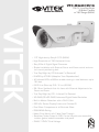
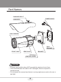
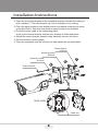
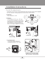
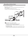
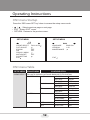
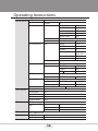
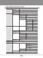
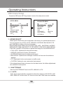
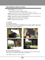
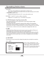
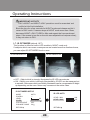
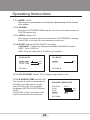
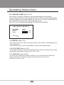
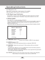
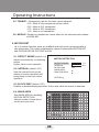
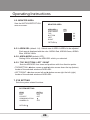
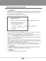
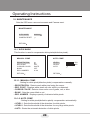
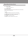
VTC-IRA40/3516
750 TV Line Day/Night
IR Bullet Camera
w/150’ Range (960H)
VITEK
• 1/3” High density Sony® CCD (960H)
• High Resolution of 750 Horizontal Lines
• Sony Effio-A Digital Signal Processor
• Simple Installation with External Focus and Zoom control and one
turn mount positioning lock
• True Day/Night by ICR (Infrared Cut Removal)
• E-WDR by ATR-EX (Adaptive Tone Reproduction)
• 40 Infrared LEDs at 850nm enable viewing in total darkness up to
150 feet
• 0.003 Lux (Sens-up Off) / 0 Lux (IR-ON)
• 3.5-16mm Varifocal Auto Iris Lens with External Adjustments for
Focus and Zoom
• True Day/Night by ICR - Infrared Cut Removal
• XD-DNR (2D+3D DNR) Advanced Digital Noise Reduction
• Built-in Motion Detection with a 24x16 Grid
• OSD (On Screen Display) menu and Camera ID
• Dual Glass Compartments to Eliminate Glare
• IP68 NEMA Rating
• Heavy Duty Mount with Cable Feed Through
• Secondary Video Output & OSD Control Joystick are accessible
inside a gasket sealed removable side panel
• 24VAC/12VDC Dual Voltage
ULTRA CLEAR RESOLUTION CAMERA
Safety Precaution
To prevent fire or shock hazard, do not expose the unit to rain or moisture.
To prevent electric shocks and risk of fire hazards, do NOT use other than
specific power source.
CAUTION: TO REDUCE THE RISK OF ELECTIC SHOCK,
DO NOT REMOVE COVER (OR BACK).
NO USER SERVICEABLE PARTS INSIDE.
REFER SERVICING TO QUALIFIED SERVICE PERSONNEL.
The symbol is intended to alert the user to the presence of uninsulated
"dangerous voltage" within the product's enclosure that may be of
sufficient magnitude to constitute a risk of electric shock to persons.
The symbol is intended to alert the user to the presence of important
operating and maintenance(servicing) instructions in the literature
accompanying the unit.
Warning :
This equipment has been tested and found to comply with the limits for a Class
A digital device, pursuant to part 15 of the FCC Rules. These limits are designed
to provide reasonable protection against harmful interference when the equipment
is operated in a commercial environment. This equipment generates, uses, and
can radiate radio frequency energy and, if not installed and used in accordance with
the instruction manual, may cause harmful interference to radio communications.
Operation of this equipment in a residential area is likely to cause harmful
interference in which case the user will be required to correct the interference at
his own expense.
Caution :
Any changes or modifications in construction of this device which are not expressly
approved by the party responsible for compliance could void the user's authority
to operate the equipment.
Mains power quality should be that of a typical commercial environment. If the user
of the model requires continued operation during power mains interruptions, it is
recommended that the model be powered from an uninterruptible power supply
(UPS) or a battery.
03
2
ULTRA CLEAR RESOLUTION CAMERA
Safety Precaution
NOTICE
The image used in this instruction manual are processed to help comprehension
and may differ from actual video of the camera.
Avoid installing areas where has shock or vibration which results in the problems.
Pay attention to safety when laying the connection cable and observe that the
cable is not subjected to heavy loads, kinks or damage and no moisture can get
in.
Never open the device such as boards or lens.
The warranty becomes void if repairs are undertaken by unauthorized persons.
Maintenance and repair have to be carried out only by authorized service centers.
Use only a mild detergent to clean the housing.
The camera should never be operated beyond the technical specifications.
This can lead to destruction.
The camera should never be operated in water.
04
3
ULTRA CLEAR RESOLUTION CAMERA
Contents
p.02~03
Safety Precaution
p.04
Contents
p.05
Features
p.05
Composition
p.06
Dimensions
p.07
Part Names
p.08~10
Installation Instructions
p.11~30
Operating Instructions
p.31
Specifications
05
4
ULTRA CLEAR RESOLUTION CAMERA
Features
Key Features
•
•
•
•
•
•
•
•
•
•
•
•
•
•
•
•
•
1/3” High density Sony CCD (960H)
750TVL High-Resolution
D-WDR by ATR-EX
TDN with Dual Filter Switcher
3.5~16mm F1.2 DC Auto Iris Vari-focal Lens
XD-DNR (2D+3D DNR) Advanced Digital Noise Reduction
Improved IR-Optimizer
DIS(Digital Image Stabilizer)
Scene Preset, LSC (Lens shading compensation), Motion detection,
E-Zoom, Polygon privacy mask(up to 15), Defog, Sens-up, BLC/HLC
External Zoom & Focus adjustment
IR-LED 40pcs
Up the Coaxial (UTC) communication
OSD Menu & Video Sub-out port for easy installation & maintenance
Circuit protection against faulty connection in power polarity
Isolated power supply against ground loop problem
Dual Window, One-touch 3-Axis locking bracket, Easy installation pad
IP68 Protection
General Description
This is an ultra-clear resolution camera which realizes over 750TVL resolution
and a crisp color reproduction with SONY 960H CCD and Effio-A Enhanced
image signal processor.
• With Effio-A series Enhanced digital imaging system,
- Delivers the crystal clear images providing 750TVL resolution in conjunction
with SONY 960H High density CCD.
- They are provided ‘D-WDR by ATR-EX’ function
- Color signal processing provides the optimum balance between the luminance
and chroma signals for high color reproducibility even for the detail scene which
contains very high spatial frequency.
- Incorporates 2D+3DNR signal processing.
• With ICR mechanism,
- Enhances its sensitivity about 10x at night time
- Can accepts the infrared light
06
5
ULTRA CLEAR RESOLUTION CAMERA
Composition
Plastic Anchor:
6 x 30mm (4pcs)
Mounting Screw:
4 x 30mm (4pcs)
Camera
Assembly Screw:
4 x 14mm (4pcs)
Mounting Template
Torque Wrench:
3mm (1pc)
Video Sub-out:
Cable (1pc)
Easy
Bracket
Operating
Instruction
Cable Signal
Sticker
Wiring Connector:
(1pc)
Dimensions
3.53” (89.6mm)
3.31” (84mm)
3.94” (100mm)
4.37” (111mm)
3.15” (80mm)
3.39” (86mm)
4.35” (110.5mm)
10.11” (256.70mm)
07
6
ULTRA CLEAR RESOLUTION CAMERA
Part Names
SUNSHIELD BOLT
POWER CABLE
SUNSHIELD
DUAL WINDOW
EASY
BRACKET
FRONT CASE
REAR CASE
BRACKET
OSD Setup
CONTROL COVER
CAUTION
• Extreme care should be taken NOT to scratch the window in front of lens.
• Care should be taken the cable is NOT damaged, kinked or exposed in
hazardous area.
• Do not expose the camera lens directly to a strong light source such as the sun or
spot light.
08
7
ULTRA CLEAR RESOLUTION CAMERA
Installation Instructions
1. Place the mounting template at the installation position and drill the ceiling or
wall if needed. ( *The easy bracket can not be installed on the ceiling)
2. Place the easy bracket on pre-drilled position and attach using the mounting
screws(4x30mm). Skip this step when an easy bracket is not installed.
3. Route the power cable to the connecting place.
Hook up the camera bracket with the easy bracket as illustrated below.
4. Attach the camera bracket through using assembly screws (4x14mm).
5. Set the camera’s viewing angle.
6. Place the sunshield onto the camera unit and tighten the sunshield-bolts.
Plastic Anchor
: 6x30mm
Mounting Screw
: 4x30mm
Assembly Screw
: 4x14mm
4
Torque Wrench
1
2
3
REAR VIEW
Cable exit
09
8
ULTRA CLEAR RESOLUTION CAMERA
Installation Instructions
Pan & Tilt adjustments
• Unlock the screw on the camera bracket through using the torque wrench supplied
• Set the camera’s viewing angle then lock the screw on the bracket.
1) Pan limit:
Pan is limited to +/- 90°.
2) Tilt limit:
Tilt is limited to 0°(2°) min ~ 90° max.
for wall(ceiling) installation respectively
with reference to the wall(ceiling) when
the inclination of camera module is 0°,
that is, the image is aligned horizontally.
90°
90°
80°
90°
• on the wall
• on the ceiling
3) Inclination limit
(Horizontal image alignment):
Inclination limited to +/-90° max.
±90°
Torque
wrench
Lock/Unlock
Screw
■ Adjustment of viewing angle
with one-touch 3-Axis bracket
10
9
ULTRA CLEAR RESOLUTION CAMERA
Installation Instructions
Zoom & Focus adjustments
Use the torque wrench supplied.
• Turn the Focus gear to “N”(Near) or “∞”(Far)
until the sharpest focus is made.
• To widen the viewing angle, turn the Zoom to
“W”(Wide) and to obtain a closer view, turn it
to “T”(Tele)
Installation and commissioning Instructions
• Make sure the power is removed before the installation.
• Follow the order for applying power.
First, connect the low voltage (AC24V or DC12V), then plug the AC adapter into
AC outlet to avoid an improper reset from power jitter and damage from the
surge voltage when no load.
Power Supply Connections
Camera can work with either 24VAC or 12VDC, dual voltage power.
Primary and secondary grounds are completely isolated to avoid possible
ground-loop problems
VIDEO (BNC)
AC24V/DC12V
AC24V/GND
N/A
N/A
※ Attach the Signal Assignment Sticker
in a visible spot for wiring reference.
11
10
ULTRA CLEAR RESOLUTION CAMERA
Operating Instructions
Using OSD controller
Setup menu can be accessed and controlled by OSD control joy stick on the
side of camera unit.
Five commands are available with the joy stick.
The design of OSD could be different according to the Model.
SUB-OUT
Cover Open
OSD Control
Joy Stick
Video Sub-out
Connector
Description of the joystick operation
1) SET Key (●) : Access to the menu or enter the setting.
To enter the main menu, press the Set Key down.
2) UP/DOWN Key (▲/▼) : Choose the desired sub-menu and to move
the cursor up or down.
3) LEFT/RIGHT Key (◄/►) : Set up the value of the selected menu. Used
to adjust the desired menu selection and to move the cursor left or right.
12
11
ULTRA CLEAR RESOLUTION CAMERA
Operating Instructions
OSD menu Startup
Press the ‘OSD menu SET key’ down to access the setup menu mode.
•
/
: Selects previous page or next page.
• EXIT : Enters ‘EXIT’ menu.
• RETURN : Returns to the previous menu.
SETUP MENU
SETUP MENU
1/2
SCENE SELECT
PICT ADJUST
EZOOM
DIS
PRIVACY MASK
MOTION DET
SYS SETTING
EXIT
2/2
FULL AUTO
LANGUAGE
VERSION
MAINTENANCE
OFF
OFF
ENGLISH
1.03
OFF
EXIT
OSD menu Table
SETUP MENU ADVANCED MENU
CONFIGURATION
SCENE SELECT FULL AUTO/ INDOOR/ OUTDOOR/ BACKLIGHT/ ITS/ CUSTOM
SHUTTER/AGC
AE LEVEL
095
AUTO
MANUAL
FIX
WHITE BAL
HLC / BLC
ATW
AGC MAX
36 DB
SENS UP
OFF
SHUTTER
1/50(1/60)
AGC MAX
44.8 DB
SHUTTER
1/50(1/60)
AGC MAX
6.0 DB
SPEED
230
DELAY CNT
020
ATW FRAME
200
ENVIRONMENT
INDOOR
CLIP LEVEL
010
OFF
HLC
13
12
ULTRA CLEAR RESOLUTION CAMERA
Operating Instructions
SCENE SELECT ATR-EX
DNR
DAY/NIGHT
LEVEL
3
AUTO
BURST
OFF
CNTL SIGNAL
EXT1
DELAY CNT
005
DAY->NIGHT
078
NIGHT->DAY
120
DAY
IR OPTIMIZER
NIGHT
BURST
OFF
ON
MODE
AUTO
IR AREA
---
LEVEL
02
IR LED
COLOR NIGHT
DAY/NIGHT
/ OFF/ FIX
OFF / ON
IR SHADE COMP
OFF / ON
PATTERN
SET1/2/3
POSH
480
POSV
290
LEVEL
MID
AUTO (default)
MODE
ON
MODE
SHUTTER FIX
SHUTTER FIX
OFF (default)
LENS SHD COMP OFF
ON
DEFOG
OFF
ON
FLK LESS
PICT ADJUST
EZOOM
OFF
ANTI CR
AUTO / OFF / ON
BRIGHTNESS
110
CONTRAST
30
SHARPNESS
08
HUE
064
COLOR GAIN
128
OFF (default)
ON
MAG
000
PAN
512
TILT
256
DIS
OFF (default) / ON
PRIVACY MASK AREA SEL
1/15
DISPLAY
OFF
14
13
ULTRA CLEAR RESOLUTION CAMERA
Operating Instructions
PRIVACY MASK POSITION
COLOR
TRANSP
MOSAIC
MOTION DET
OFF (default)
ON
DETECT SENSE
111
INTERVAL
001
BLOCK DISP
OFF
MASK AREA
MONITOR AREA
SYS SETTING
LENS
AUTO
AREA SEL
1/4
AREA MODE
OFF
TOP
03
BOTTOM
04
LEFT
04
RIGHT
TYPE
08
DC
MODE
AUTO
ADJUST
SPEED
FLIP
CRT
LCD / CRT
COMMUNICATION* PROTOCOL
(Option)
ADDRESS
CAMERA ID
030
OFF / V / H / HV
PELCO-D
001
BAUDRATE
9600
DATABIT
8
PARITY
OFF
STOPBIT
1
OFF / ON
LANGUAGE
English/ Spanish/ Russian/ Portuguese/ German/ French/ Chinese/ Japanese
VERSION
1.03
MAINTENANCE W.PIX MASK
MANUAL
REGISTRATION
REG. POINT
CURSOR COLOR
BLINK
AUTO
REG. NUMBER
LEVEL1 / LEVEL2 / AUTO
DATA CLEAR
YES / NO
CAMERA RESET
EXIT
SAVE / NOT SAVE / CANCEL / BACK
15
14
ULTRA CLEAR RESOLUTION CAMERA
Operating Instructions
OSD menu Setup
Press the OSD menu SET key down to access the setup menu mode.
SETUP MENU
ADVANCED MENU
1/2
SCENE SELECT
PICT ADJUST
EZOOM
DIS
PRIVACY MASK
MOTION DET
SYS SETTING
EXIT
1/2
FULL AUTO
SHUTTER/AGC
WHITE BAL
HLC/BLC
ATR-EX
DNR
DAY/NIGHT
IR OPTIMIZER
RETURN
OFF
OFF
OFF
AUTO
ATW
OFF
NIGHT
ON
1. SCENE SELECT
These options have been pre-configured at the factory for optimal performance.
You can choose one of FULL AUTO, INDOOR, OUTDOOR, BACKLIGHT, ITS
and CUSTOM according to the environments.
Each SCENE preset offers how to set SHUTTER +AGC, WHITE BAL, HLC/BLC,
WDR/ATR-EX, DNR, DAY/NIGHT, IR OPTIMIZER, LENS SHD COMP, DEFOG,
FLK LESS, and ANTI CR functions to get the best image for the SCENE SELECT.
> FULL AUTO: Optimized for the general scene.
> INDOOR: Optimized of indoor environment.
> OUTDOOR: Optimized of outdoor environment.
> BACKLIGHT: Optimized for backlight condition such as near the window in
daylight.
> ITS: Optimized for the environment on traffic roads.
> CUSTOM: Setting for user customized environment.
If the selected preset does not seem to be the best choice, the further adjustments
are available in each preset.
1-1. SHUTTER/AGC
Sets the SHUTTER/AGC level to AUTO, MANUAL or FIX.
1-1-1. AUTO:
Video level is automatically controlled to follow the settings of AE LEVEL, AGC
MAX, SENS UP. In this mode, ‘DC Auto Iris Lens’ and ‘Fixed Lens’ are available.
16
15
ULTRA CLEAR RESOLUTION CAMERA
Operating Instructions
1-1-2. MANUAL:
Video level is manually controlled by the settings of SHUTTER, AGC MAX.
In this mode, ‘DC Auto Iris Lens’ is only available.
1-1-3. FIX:
Video level is fixed in any conditions by the setting of SHUTTER, AGC MAX.
1-2. WHITE BAL
Can set the WHITE BALANCE mode.
1-2-1. ATW (Auto Trace White Balance):
Automatically tracks the changes of color temperature and continuously
adjusts the white balance. The white balance range is 1,800°K~10,500°K.
Note: If you set to ‘CUSTOM’ mode in ‘SCENE SELECT’ menu, the ‘WHITE BAL’
sub-menu will be appeared ‘ATW/ PUSH/ USER1/ USER2/ MANUAL/
PUSH LOCK’ functions that you can select one.
Other modes in ‘SCENE SELECT’ menu, the ‘WHITE BAL’ sub-menu is
only ‘ATW’ function.
ATW
SPEED
DELAY CNT
ATW FRAME
ENVIRONMENT
230
020
200
INDOOR
RETURN
• SPEED (default: 230):
Sets the AWB(Automatic White Balance) compensating speed. Lower value makes
AWB faster. * Too fast AWB may make the color oscillation.
• DELAY CNT (default: 020):
Adjusts the AWB compensation delay to next update of AWB.
The smaller value will update AWB more frequently (faster).
• ATW FRAME (default: 200):
Determines the ATW range with respect to the fundamental range. Higher value
extends the ATW range at lower and higher color temperature.
17
16
ULTRA CLEAR RESOLUTION CAMERA
Operating Instructions
• ENVIRONMENT (default: INDOOR):
Selects INDOOR, SUNNY, SHADE or AUTO
Their ATW is optimized for the limited application and can not cover
> INDOOR : Optimized for Indoor installation and more easily compensates ATW
for low color temperature such as incandescent lights.
> SUNNY : Optimized for outdoor sunlight applications and more easily compensates
ATW for high color temperature such as sunlight.
> SHADE : Optimized for shade area compensation.
> AUTO : Optimized for general scene.
1-3. HLC/BLC
HLC (Highlight Cut out) :
This function is used to black out highlighted areas, in order to enable a clear visual
image of objects, such as the license plates of an oncoming vehicle or other objects
that may be obstructed by headlamps.
HLC OFF
HLC ON
BLC OFF
BLC ON
BLC (Backlight Compensation) :
This function is used to brighten an image in the foreground with a highly light area
behind it such as sunlight, limiting the affect of silhouette.
1-3-1. OFF: Disables HLC and BLC functions.
18
17
ULTRA CLEAR RESOLUTION CAMERA
Operating Instructions
1-3-2. HLC:
HLC clips out the highlight area and masks it as black color.
Video will be clipped out and masked for the area which exceeds CLIP LEVEL.
• CLIP LEVEL (default: 010):
Defines the threshold level for HLC. Lower value masks more.
1-3-3. BLC: Sets BLC function enables or disables
Note: BLC is available only in ‘CUSTOM’ scene preset.
1-4. ATR-EX (Adaptive Tone Reproduction-EX)
Sets enabling/disabling ATR compensation for the better dynamic range
(D-WDR) of the image.
ATR feature improves the dynamic range and the visibility of the image by
providing the optimal gradation compensation of the image in one field. This is
achieved by two ways of image processing, luminance compression and contrast
enhancement, so that the tone can be enhanced at highlight and dark area.
1-5. DNR
DNR(Digital Noise Reduction) function improves picture quality by filtering out
signal noise which is generated under the low light conditions.
It is 3DNR(3-dimensional noise reduction) which reduces the noise by the multi
frames. Noise Reduction is effective at low light. Setting high level is strength of
noise reduction but the result may occur in loss of sharpness and the tail effect
of a comet.
1-6. DAY/NIGHT
This function is used to control the setting during day-time and night-time operation.
1-6-1. AUTO
AUTO mode in DAY/NIGHT is used
only for a camera which does not have
a light sensor. Camera switches DAY
from/to NIGHT automatically along with
the amount of light through the lens.
D/N AUTO SETUP
BURST
CNTL SIGNAL
DELAY CNT
DAY->NIGHT
NIGHT->DAY
OFF
EXT1
005
078
120
RETURN
19
18
ULTRA CLEAR RESOLUTION CAMERA
Operating Instructions
• BURST (default: OFF)
BURST determines whether a color burst signal keeps output or eliminated
when camera switches to B/W.
If set to ON, B/W video signal contains color burst signal and is compatible
with the color equipment but shows the same resolution as color video.
If set OFF, the color burst signal is removed from B/W video and shows better
resolution but rarely the compatibility problem may occur with the color equipment.
• CNTL SIGNAL (default: EXT1):
DAY/NIGHT is switched by amount of light through the lens.
Selects one of ‘INT/EXT1/EXT2’
• DELAY CNT (default: 005)
DELAY CNT is time in second while camera maintains its status before Day↔
Night switches. DELAY can avoid the unwanted/frivolous switching by a short
term lights such as light from the passing car.
• DAY -> NIGHT (default: 078)
DAY→NIGHT is a threshold level which determines to switch from DAY to
NIGHT. Lower(Higher) value makes the camera switch from Day to Night at
lower(higher) illumination. If it stays in Day(Color) mode at night time, increase
DAY→NIGHT threshold value until it just switches to Night.
* Examine and verify Day/Night operation according to IMPORTANT ACTIVITY
• NIGHT -> DAY (default: 120)
NIGHT→DAY is a threshold level which determines to switch from NIGHT to
DAY. Lower(Higher) value makes the camera switched from Night to Day at
lower(higher) illumination. If it stays in Night(B/W) mode at day time, decrease
NIGHT->DAY threshold value until it just switches to Day
* Examine and verify Day/Night operation according to IMPORTANT ACTIVITY
1-6-2. DAY : The camera is always in Color mode.
1-6-3. NIGHT : The camera is always in B/W mode.
• BURST (default: OFF) :
Sets the BURST option ON/OFF to output burst signal in B/W mode.
CAUTION
• Verify ‘DAY/NIGHT’ after completing all settings of lens for zoom and focus.
• If the gap between DAY->NIGHT and NIGHT->DAY is too small, camera may
repeat switching DAY from/to NIGHT. If NIGHT->DAY is decreased from the
Factory default, the same amount is recommended for DAY->NIGHT to avoid
repeating DAY<->NIGHT unintentionally.
20
19
ULTRA CLEAR RESOLUTION CAMERA
Operating Instructions
IMPORTANT ACTIVITY
DAY->NIGHT and NIGHT->DAY operations must be examined and
verified at the final installation.
Block the lens for a few seconds for NIGHT mode and release and let it
return to DAY mode. If camera stays at NIGHT mode more than 10sec,
decrease NIGHT->DAY THRES a little and repeat the fore-mentioned
steps. If the scene is too dim or lens iris was adjusted too low(near close),
it may not return to DAY.
1-7. IR OPTIMIZER (default: OFF)
This function is effective built-in LED models in NIGHT mode only.
If subjects which can cause overexposure are located near the monitored area,
you can adjust IR OPTIMIZER level or area.
IR OPTIMIZER ON
IR OPTIMIZER OFF
● OFF : Object which is strongly illuminated by IR LED can saturate.
● ON : Object even which is strongly illuminated by IR LED can be managed not
to saturate. Side areas which are weakly illuminated can be compensated to bright
up depending on the case. Noise may increase at the entire video.
IR OPTIMIZER SETUP
MODE
IR AREA
LEVEL
IR LED
COLOR NIGHT
IR SHADE COMP
IR LED AUTO
AUTO
---
LEVEL MIN
LEVEL MAX
02
DAY/NIGHT
OFF
ON
RETURN
RETURN
21
20
006
255
ULTRA CLEAR RESOLUTION CAMERA
Operating Instructions
1-7-1. MODE : AUTO
Reducing the over-saturation is automatically adjusted along with the location
of the subject.
1-7-2. IR AREA :
Sets the IR OPTIMIZER AREA and the function works selected area in
‘CUSTOM preset only.
1-7-3. LEVEL (default: 02):
This function is used to adjust the overall when IR OPTIMIZER is working.
If the LEVEL is too high, the over-saturation could occur.
1-7-4. IR LED: Sets the IR LED ON/OFF controlling
• DAY/NIGHT : Follows the setting automatically DAY/NIGHT function.
• OFF : Turns IR LED off.
• FIX : Fixes the brightness of IR LED in any condition.
IR LED AUTO
LEVEL MIN
LEVEL MAX
IR LED FIX
006
255
255
LEVEL
RETURN
RETURN
1-7-5. COLOR NIGHT (default: OFF): Displays night video in color.
1-7-6. IR SHADE COMP (default: ON):
This function is used to compensate for
IR shade of the side area on screen
when IR LED is ON. You can adjust
the shading PATTERN, POSITION and
LEVEL.
If the LEVEL is high, the screen noise
could be increased at the side area.
22
21
IR SHADE COMP SETUP
PATTERN
POSH
POSV
LEVEL
RETURN
SET2
MID
480
246
ULTRA CLEAR RESOLUTION CAMERA
Operating Instructions
1-8. LENS SHD COMP (default: OFF)
This function is used to caculate the compensation data for lens shading.
Convex shape of the lens causes the light to enter the camera unevenly and typically
makes the center of the screen brighter than the rest. It is used to compensate for
this undesirable effect and make the screen more even.
Set to ‘ON’, you can adjust the shading PATTERN and POSITION.
LENS SHADE COMP SETUP
PATTERN
POSH
POSV
SET1
480
246
RETURN
1-9. DEFOG (default: ON)
This function is used to carry out defog function. Sets LEVEL to eliminate amount
of fog on screen.
If the DEFOG is set to ON, the WDR/BLC function will be deactivated.
1-10. FLK LESS (default: AUTO)
This function is used to remove the flickering on screen due to differences in light
and electric frequencies. Selects AUTO, OFF or ON.
1-11. ANTI-CR (default: AUTO)
This mode can minimize the problems related to color rolling caused by differences
between the flicker of fluorescent lights and the frequency of the camera.
Selects AUTO, OFF or ON
23
22
ULTRA CLEAR RESOLUTION CAMERA
Operating Instructions
2. PICT ADJUST
PICT ADJUST
BRIGHTNESS
CONTRAST
SHARPNESS
HUE
COLOR GAIN
110
30
08
064
128
RETURN
2-1. BRIGHTNESS (default: 110):
Increases or decreases the brightness of the picture.
This is different from that of DC iris lens and simply increases or decreases the
digital gain of video. Do not increase this too much, the dynamic range for the
highlight area will decrease.
2-2. CONTRAST (default: 30):
Adjusts the strength of the image contrast. If set to too high, the dark area may loss
detail and the high luminance area may saturate.
2-3. SHARPNESS (default: 08):
Increases or decreases the sharpness of the picture.
Too much sharpness can make image harsh and show more noise as well as line
flicker at the edge of object in the picture.
2-4. HUE (default: 064): Adjusts hue for NTSC version only.
2-5. COLOR GAIN (default: 128): Increases or decreases the color saturation.
3. EZOOM (default: OFF):
Sets the maximum digital zoom magnification. E.ZOOM function enlarges the
pixel itself, which can cause deterioration of the picture quality.
3-1. MAG (default: 000):
MAG is the magnification ratio of the electronic zoom. Sets from x000 to x255.
3-2. PAN (default: 512):
When MAG is greater than 0, the electronic pan is available.
000 is the left most pan and 1023 is the right most pan.
24
23
ULTRA CLEAR RESOLUTION CAMERA
Operating Instructions
3-3. TILT (default: 256):
When MAG is greater than 0, the electronic tilt is available.
000 is the upper most tilt and 511 is the lower most tilt.
4. DIS (Digital Image Stabilization)
This function is used to reduce and stabilizes the shaky image from a camera
installed in the vibrated area. FOV(Field of view) will be reduced if set to ON.
5. PRIVACY MASK
Sets ON/OFF for enabling/disabling PRIVACY.
Up to 15 privacy areas are available and each area is programmable in size and
location. The number of privacy areas is limited to four when MOTION DET >
MONITOR AREA is ON.
The privacy areas are masked with the color selected by PRIVACY MASK>COLOR.
PRIVACY MASK SETUP
AREA SEL
DISPLAY
POSITION
COLOR
TRAMSP
MOSAIC
1/15
OFF
-----------------
RETURN
5-1. AREA SEL (default: 1/15): Selects one of AREA1~AREA15 to be adjusted.
5-2. DISPLAY (default: OFF)
Displays OFF/ON for the mask area which you selected ‘AREA SEL’
5-3. POSITION : Adjusts the mask area X,Y-Axis position which you selected
‘AREA SEL’
• TOP/BOTTOM: ◄button moves up and ►button moves down the top (bottom)
border of the selected window at AREA SEL.
• LEFT/RIGHT: ◄button moves left and ►button moves right the left (right) border
of the selected window at AREA SEL.
5-4. COLOR : Selects one of 8 colors (Red, Green, Blue, Yellow, Cyan, Magenta,
White, Black) for the selected mask window at AREA SEL.
25
24
ULTRA CLEAR RESOLUTION CAMERA
Operating Instructions
5-5. TRANSP : Transparency rate for the mask can be adjusted.
0.00 - Mask is fully transparent and not visible.
0.50 - Mask is 50% transparent.
0.75 - Mask is 25% transparent.
1.00 - Mask is not transparent.
5-6. MOSAIC : Enables or disables the mosaic effect for the selected mask window
at AREA SEL
6. MOTION DET
Up to 4 motion detection areas are available and each area is programmable in
size and location. The motion is displayed by means of blocks when MOTION DET
and MOTION DET>BLOCK DISP are ON.
6-1. DETECT SENSE (default:111)
MOTION DETECTION
Adjusts the sensitivity for detecting
motion.
Higher value is more sensitive.
DETECT SENSE
INTERVAL
BLOCK DISP
MASK AREA
MONITOR AREA
6-2. INTERVAL (default: 001)
Sets the interval time from the
starting of motion operation until
being ready for the next motion
operation.
111
001
OFF
RETURN
6-3. BLOCK DISP (default: OFF)
Enables or disables displaying blocks for the area which the motion is detected.
6-4. MASK AREA
Sets MASK AREA for disabling
MOTION DETECTION.
Selects number of area sels to
set the area you need.
1
2
3
4
5
6
7
8
9 10 11 12
13 14 15 16 17 18 19 20 21 22 23 24
25 26 27 28 29 30 31 32 33 34 35 36
37 38 39 40 41 42 43 44 45 46 47 48
49 50 51 52 53 54 55 56 57 58 59 60
61 62 63 64 65 66 67 68 69 70 71 72
73 74 75 76 77 78 79 80 81 82 83 84
85 86 87 88 89 90 91 92 93 94 95 96
RETURN
26
25
ULTRA CLEAR RESOLUTION CAMERA
Operating Instructions
6-5. MONITOR AREA
Sets the MOTION DETECTION
area on screen.
MONITOR AREA
AREA SEL
AREA MODE
TOP
BOTTOM
LEFT
RIGHT
1/4
OFF
03
04
04
08
RETURN
6-5-1. AREA SEL (default: 1/4) : Selects one of AREA1~AREA4 to be adjusted.
Each area is displayed with the color. AREA1-Red, AREA2-Green, AREA3Blue, AREA4-Yellow
6-5-2. AREA MODE (default: OFF):
Setting ON is activated the AREA SEL which you selected.
6-5-3. TOP/ BOOTTOM / LEFT / RIGHT
Sets the AREA SEL box sizes and positions with four direction points.
• TOP/BOTTOM: ◄button moves up and ►button moves down the top (bottom)
border of the selected window at AREA SEL.
• LEFT/RIGHT: ◄button moves left and ►button moves right the left (right)
border of the selected window at AREA SEL.
7. SYS SETTING
Sets the system related functions.
SYSTEM SETTING
LENS
FLIP
LCD/CRT
COMMUNICATION
CAMERA ID
AUTO
OFF
CRT
OFF
RETURN
27
26
ULTRA CLEAR RESOLUTION CAMERA
Operating Instructions
7-1. LENS
: Selects the lens type, AUTO or MANUAL. AUTO supports DC auto-iris lens only.
7-1-1. AUTO
• TYPE (default: DC):
This camera does NOT support video type auto iris lens.
MUST BE SET TO DC ONLY.
• MODE (default: AUTO):
Lens iris is automatically controlled according to the scene light level.
• ADJUST : Adjusts lens open control regardless of the light level.
• SPEED (default: 30):
Adjusts the iris control speed. The lower value is the faster speed.
If the speed is too slow or fast, the iris control may be unstable.
7-2. FLIP (default: OFF): It is used to inverse the pictures coming from the camera.
• V : Flips the video signals vertically.
• H : Flips the video signals horizontally.
• HV : Flips the video signals horizontally and vertically.
7-3. LCD/CRT (default: CRT):
Selects the correct type of viewing monitor will ensure the most optimal picture.
7-4. COMMUNICATION
Sets the communication related function.
PROTOCOL(PELCO-D), BAUDRATE(9600), DATABIT(8), PARITY(OFF),
STOPBIT(1) are fixed. Can sets only ADDRESS number.
COMMUNICATION
PROTOCOL
ADDRESS
BAUDRATE
DATABIT
PARITY
STOPBIT
PELCO-D
001
9600
8BIT
OFF
1BIT
RETURN
28
27
ULTRA CLEAR RESOLUTION CAMERA
Operating Instructions
7-5. CAMERA ID
Sets ON/OFF for enabling/disabling of ID display. Factory default ID is Software
version of camera. User programmed camera ID will be lost and restored with
factory default ID by CAMERA RESET.
Up to 40 characters can be input for camera ID.
CAMERA ID SETUP
CAMERA ID input line
VER-DN1.0
ABCDEFGHIJKLMNOPQRSTUV
WXYZ0123456789-!”#$%&’(
)_`,¥:;<=>?@\^*↑↓←→/
CHR1
CHR2
CLR
POS
COMMAND line
RETURN
● Use four direction buttons (▲/▼/◄/►) to move a block cursor in character
table and press a set button (◙) to input the selected character.
To move the character input position on CAMERA ID input line, move a cursor
to ← or → on COMMAND LINE and press a set button on ← or →.
● CLR : To clear CAMERA ID input line, move a cursor to CLR on COMMAND
LINE and press a set button (◙).
● POS : To set the location of CAM TITLE to be displayed on the monitor, move
a cursor to POS and press a set button (◙) and then the OSD menu disappears
and CAMERA ID will be displayed on the monitor.
Move CAMERA ID where desired position by using four direction buttons
(▲/▼/◄/ ►) then press a set button (◙) to fix. The OSD Menu will appear again.
8. LANGUAGE
8 languages, ENGLISH, SPANISH, RUSSIAN, PORTUGUESE, GERMAN,
FRENCH, CHINESE and JAPANESE are available.
9. VERSION
The camera firmware version is displayed.
29
28
ULTRA CLEAR RESOLUTION CAMERA
Operating Instructions
10. MAINTENANCE
Sets the OSD menu user environments and Camera reset.
MAINTENANCE
W.PIX MASK
CAMERA RESET
MANUAL
RETURN
10-1. W.PIX MASK
This function is used to compensate white pixels(defective pixels).
MANUAL COMP
REGISTRATION
REG.POINT
CURSOR COLOR
BLINK
REG. NUMBER
AUTO COMP
LEVEL1
LEVEL2
AUTO
OFF
WHITE
OFF
0 / 64
RETURN
003
255
RETURN
10-1-1. MANUAL COMP
: Setting for white pixel(defective pixels) compensation manually.
• REGISTRATION : Detects each white pixel using the cursor.
• REG. POINT : Displays white pixels on color which you detected.
• CURSOR COLOR : Selects cursor color one of green, red, or blue.
• BLINK : Sets the cursor blink or not.
• REG. NUMBER : Displays quantity of detected white pixels.
10-1-2. AUTO COMP
: Setting for white pixels(defective pixels) compensation automatically.
• LEVEL1 : Sets the threshold of the detection for white pixels.
• LEVEL2 : Sets the threshold of the detection for very large white pixels.
• AUTO : Starts the automatic detection of white pixels.
30
29
ULTRA CLEAR RESOLUTION CAMERA
Operating Instructions
10-1-3. DATA CLEAR
: Clear the W.PIX data or not.
10-2. CAMERA RESET
This function is used to reset to the factory defaults of the camera settings.
RESET and EXIT the OSD menu.
11. EXIT
Exits SETUP MENU and returns to the normal display.
11-1. SAVE : Save all the setting before exit the setup menu.
11-2. NOT SAVE : Exit the setup menu without save.
11-3. CANCEL : Cancel the exit mode.
11-4. BACK : Go back to the previous menu mode.
31
30
Detailed Specifications
Image Device
1/3” 960H High Density Sony® CCD
750TV Lines
Resolution
976(H) x 494(V)
Effective Pixels
Minimum Illumination
0.003 Lux (Sens-up Off) / 0 Lux (IR-ON)
40 850nm IR LEDs
Infrared LEDs
IR Distance
Over 150 Feet
Built-In Lens
3.5-16mm DC A/I, Switched IR Cut Filter D/N Lens
True Day/Night by ICR
Day/Night
E-WDR by ATR-EX
WDR
Noise Reduction
XD-DNR (2D+3D DNR)
Motion Detection
24x16 Grid
Privacy Mask
Up to 15 programmable mask areas
White Balance
ATW / PUSH / USER1 / USER2 / MANUAL / PUSH LOCK
HLC/BLC
Light Compensation
52dB with AGC OFF at 50 IRE
S/N Ratio
1/60~1/100,000sec
Electronic Iris
IP68
Water Resistance
Power Source
UL Certified: 12VDC/24VAC (Dual Voltage)
Power Consumption (12VDC)
110mA / 520mA (IR OFF/ON)
Power Consumption (24VAC)
120mA / 470mA (IR OFF/ON)
-4ºF~122ºF (-20ºC~50ºC)
Installation Temperature
Operation Temperature
-58ºF~122ºF (-50ºC~50ºC) @ 85%RH
Length
Ceiling Mounted: 9.5” (241mm) / Wall Mounted: 11.375” (289mm)
Width
Camera: 3” (76mm) / Camera w/Sun Shield: 4.375” (111mm)
Height
Ceiling Mounted: 6” (152mm)
Weight
2.65 lbs. (1202g)
31
LIMITED LIABILITY WARRANTY
VITEK products carry a three (3) year limited warranty. VITEK warrants
to the purchaser that products manufactured by VITEK are free of any
rightful claim of infringement or the like, and when used in the manner
intended, will be free of defects in materials and workmanship for a
period of three (3) years, or as otherwise stated above, from the date of
purchase by the end user. This warranty is nontransferable and extends
only to the original buyer or end user customer of a VITEK Authorized
Reseller.
The product must have been used only for its intended purpose, and
not been subjected to damage by misuse, willful or accidental damage,
caused by excessive voltage or lightning.
The product must not have been tampered with in any way or the guarantee will be considered null and void.
This guarantee does not affect your statutory rights.
Contact your local VITEK Reseller should servicing become necessary.
VITEK makes no warranty or guarantee whatsoever with respect to
products sold or purchased through unauthorized sales channels. Warranty support is available only if product is purchased through a VITEK
Authorized Reseller.
28492 Constellation Road Valencia, ca 91355
WWW.VITEKCCTV.COM
Version 3.0
December 2014


![[B40] RWS-TE2PAFZ39-IR(Videor)](http://vs1.manualzilla.com/store/data/005979657_1-986d79b0350f507a65bc366834e972e4-150x150.png)