1
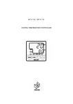
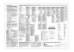
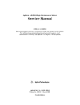
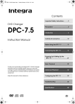
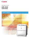
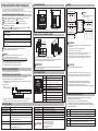
TTM-i4N SERIES USER'S MANUAL
WIRING
OUTER DIMENSION
48
Thank you for purchasing model TTM-i4N SERIES Digital Temperature Controller.
Please go through this Instruction Manual carefully and use the unit in proper manner.
If the unit is used in a manner not specified by the manufacturer,the protection provided the unit may be impaired.
4
( 2)
59
OUT2/EV2
NOTICE/WARNING BEFORE OPERATION USE
: Cautions,Danger of Electric Shock
: Reinforced/dual insulation
When having the purchased controller at hand,please be sure that its correct model.
See the following “Model Configuration” .
The following symbol marks provide to prevent incident or damage.Kindly refer to the details
of the WARNING/CAUTION when using for the first time.
WARNING
Due to mishandling,the serious damages may occur to the operator,such as death,
electrocution or skin burn.
OUT1
NO ②
③C
Relay Output AC250V 3A (Load resistance)
Watertight packing
※Clean the unit by well squeezed cloth with water.
WARNING
Make sure the correct wiring connection before turning on electricity.
Mis-wiring may cause malfunction of the unit and fire.
Never modify the unit to prevent damage or incident such as malfunction and fire etc.
・Please put this user's manual aside for your reference,when operating the unit.
・Copy or reprint of this manual,wholly or partially,is not allowed.
・The contents of this manual may change without notice in future.
INSTALLATION CONDITIONS
・Indoor use ・Altitude up to 2000m ・Pollution Degree 2
ACCESSORY & CONFIGURATION
TTM-i4N- -A
Code
R
P
+0.6
(48×n−3)
0
Installation Attachment
・Install the unit in either horizontal or vertical ( upward ) direction.
・When fitting the product,give more than 12 mm space between the upper / lower / left & right
& backface portion to the product and the peripheral device or plates.
CAUTION
NO ⑦
⑥C
Relay Output AC250V 1A (Load resistance)
Temp. INPUT
④
⑧b
⑨B
⑩A
⑧⑨+
⑩
⑤
RTD
TC
・Use specified size (M3.5 width 7.3 mm or less) crimped terminals for wiring and
machines & tools.
・A conformity wire : copper / AWG18-24 / Temp.rating 80℃
・Tightening torqe : 0.5 Nm ( 5 kgfm, 4.43 lb.fin)
・Make sure the wiring is done correctly for any wires with polarity ( + and - ).
・For relay contact output, “C : common” and “NO : normal open” .
・Temp.INPUT and OUT1 in case of SSR Output,only the secondary circuits
with reinforced/dual insulation from the primary side can be connected.
CAUTION
・This Controller is not equipped with overcurrent protection device ( Fuse ).
Please prepare semi-time lag fuse ( rated voltage : 250V, rated current : 1A )
when making power source wiring. A Fuse is connected to the live side.
M KEY
For change of display
F KEY
For action of function setting
▲▼KEY Up down key for change of setting value.
Holding the U/D keys changes value at a rapid rate.
PV
Measured value indication,Charactor indication
SV
Set value indication,Operation quantity indication
OUT
Output monitor(appears when OUT1 is ON)
AL1
Alarm1 monitor(appears when EV1 is ON)
AL2
Alarm2 monitor(appears when EV2 is ON)
It also lights when OUT2 is ON in Heating/Cooling Control mode.
RDY
RDY lamp(It appears in Ready condition)
℃
℉
It lights-up when the set value in the Temp. data is Celsius.
It lights-up when the set value in the Temp. data is Fahrenheit.
SPECIFICATIONS
Input Power Requirments
AC100 to 240V, 50/60Hz
Event1
Relay Contact Output AC250V 1A MAX
Operating Voltage Range
OUT2 / EV2 ( Option )
Relay Contact Output AC250V 1A MAX
Power Consumption
85% to 110% of the rated voltage
6VA MAX
Operation Environment
0 to 50℃, 20 to 90%RH ( Avoid making of dew )
Memory Element
EEPROM
Storage Environment
-25 to 75℃, 5 to 95%RH ( Avoid making of dew )
Input of Sensor
a) Thermocouple Input ( type:K,J,R,T,N,S,B )
b) 3-wire Resistance Temperature Detector Input ( type:Pt100,JPt100 )
(Changeable by input type selection)
Weight
Less than 100 gms.
a) Relay Contact Output AC250V 3A MAX
b) SSR Driving Voltage Output DC12V 600Ω( or more )
( Output type depends on the model. )
⑦
⑧
⑨
⑩
PARTS INDICATION
・This product is intended for use with industrial machineries,machine tools and measurement
instruments.(It is not to be used with medical equipment which involves human lives).
OUT1 (Control Output )
②
③
④
⑤
EV1
・Do not touch the terminal part while the power is on.
OUT1
Relay Contact Output
SSR Driving Voltage Output
3 kinds of PID,ON/OFF
⑥
・When you use compressed lead wire to install multiple units,please be careful sufficiently
not to touch the other lead wires.
Option
OUT2/EV2 Relay Contact Output
Control Method
①
WARNING
Multiple Unit Installation
Option
Code
B
100 to 240V AC 50/60HZ 6VA
(NO polarity)
Single Unit Istallation
1) Please be sure that the unit enclosed in packing carton is a right model before using.
2) Kindly check the following accessory being contained in that carton box.
・Installation Attachment ( For installation,please see “PANEL CUTOUT & INSTALLATION” on the right.)
・This user's manual : 1 copy
3) Model Configuration
OUT1
② + - ③
SSR Driving Voltage Output DC12V
Exactly same potential wires for EV1 and EV2
circuits can be connected.
POWER SUPPLY
45
60(or more)
CAUTION
※Terminal ⑥
+0.6
0
+0.
6
0
CAUTION
For prevention of its malfanction,do not push the front key with sharp points.
Spare terminal must not be used for other purposes.
※This packing is not attached
when Option-B is not specified.
PANEL CUTOUT & INSTALLATION
45
Owing to mishandling,the operator may be inflicted with slight injury,or may cause some
damage to the unit.
WARNING
⑥C
NO ①
Relay Output AC250V 1A (Load resistance)
48
The meaning of the symbols indicated on the label found at the side of the unit is as follows.
: Alternating current
: Cautions,Danger,Refer to a manual
※OUT2 / EV2 is not available when Option-B is not specified.
Installation Environment
CAUTION BEFORE CONTROL
・Setting program is stored after power OFF,as non-volatile memory is equipped with
TTM-i4N SERIES controllers for setting storage.
・Either thermocouple or R.T.D ( Pt100 / JPt100 ) is selectable input type.
For suitable apprication,please select most appropriate input type and adjust input setup.
・PID or ON/OFF control is selective for the optimal performance and each detail of features is
specified in the table as bellow.
Merit
・Gas of corrosion,dust and oily smoke.
・The electrical noise of the generator.
・The influence of electromagnetic field.
・Mechanical vibration and shock.
・The direct sunlight.
PID Control
Better control result is achieved as opposed to that of ON/OFF control.
Demerit Life span of relay is shorter,as output exists freduently with relay contact.
Overvoltage Category Ⅱ
Location of the Unit Setting Keep away from the following:
CAUTION
・The use of Noise Filter close to the Power Supply terminal is recommended.
Recommended Noise Filter:RSEL-2002W/A(available from TDK Lambda)
Noise filter's terminal 3 and 4 should be connected to the unit.
Noise filter's body may or may not to be connected to frame ground. Both are acceptable.
Merit
ON/OFF Control
Life span of relay is generally longer,as it is ON when temperature is below SV
and it is OFF when temperature is over SV ( For heating control ).
Demerit Control value is worse in comparison with that of PID control.
OPERATION FLOW AND SETTING MENU
●Setting mode
●POWER ON
“Input type setting screen” appears for 4seconds,
then it will oriceed to “Run mode” .
<SET0 : Priority screen setting mode>
<SET1 : Input setting mode>
1. Setting item selection screen
1. Setting item selection screen
▲KEY
SET0
PR1
Setting for priority screen
(Refer to Ex.1.)
SET1
INP
▼KEY
M key
M key
●RUN mode
Measured value
Set value
PRI1
M key
B. Priority screens (1 ~ 9) PRI2
OFF
PRI3
Select 3rd screen on
Run mode B
OFF
M key
(Press for 4 seconds)
M key
5. Priority screen 4 setting
M key
(Press for 2 seconds)
PRI4
Select 4th screen on
Run mode B
OFF
●Protect setting mode
M key
6. Priority screen 5 setting
Setting screen
Mode to set the protection level
PTLV
0
0 Non-Protect
1 ・Setting change for SV/Priority Screen is Possible
PRI5
Select 5th screen on
Run mode B
OFF
M key
7. Priority screen 6 setting
・The Setting Mode Parameter blinds
parameters except for the following:
PRI6
Select 6th screen on
Run mode B
OFF
PV compasation zero setting
Alarm reset
AT start/reset
Proportional band setting for OUT1/OUT2
Integral time setting
Deviative time setting
Control sensitivity setting for OUT1/OUT2
Upper limit setting for EV1/EV2
Lower limit setting for EV1/EV2
M key
8. Priority screen 7 setting
PRI7
Select 7th screen on
Run mode B
OFF
100
PVS‘
0
Select 8th display on
Run mode B
OFF
M key
10. Priority screen 9 setting
2 ・Setting change is possible with SV only.
・The priority screen is with indication/
Setting Change not possible.
・All setting mode parameters will be blinded.
PRI9
00
DP
0
*C
0
0
‘1
‘2
‘3
Setting range : 0.0 ~ 99.9
Setting unit : seconds
CNT
‘020++
①
②
③
0 0
Screen for Alarm reset of EV1/EV2
※Press F key for 1 second to reset the alarm.
(The indication momentarily disappears as
the Alarm reset is executed).
0
0
1
1
M key , return to 1
0
1
0
1
DIR‘
0
MV1‘
00
●EX1. Priority screens & its setting
eg:Basic screen → OUT1 manipulated value → Setting high limit for EV1
<When select PID control>
8. Tuning type setting
*Screen is shifted when pressing M key each time.
<When select ON/OFF control>
*1
1
●EX2. Function key works
This function is to enable F key to use as a specific key,for the following actions
selected in F key setting belonging to setting mode.
Function
1. Digit shift
Setting digit shift is enabled when setting value is changed.
Digit under selection will blink.
Effective
in all modes
2. RUN/READY
AT(Auto -Tuning) starts instantly after pressing F key.
Start and Reset are alternately switched by F key.
Effective only
in Operating mode
4. Timer Start / Reset Start and Reset are alternately switched by F key.
Press once for function.
6. Enter Effective
in all modes
Press once for function.
ATC
2
CP1
0
*1
Setting range : 0 ∼ 999 or 0.0 ∼ 999.9
Setting unit : ℃ or ℉
0
*1
Over shoot protection PID
*1
If control is unstable under self-tuning,
please change to type A ,B or FUZZY and also ON/OFF control.
0
D
●EX4. ARW (Anti-Reset-Windup)
0
・ARW controls integral action (PV accords with SV).
・If integral value goes down,it takes effects.
If integral value is set “0” ,it stops integral action.
0.0 Setting
-199.9 ~ 999.9
-199.9 ~ 850.0
-
-199.9 ~ 400.0
-199.9 ~ 999.9
-
-
-199.9 ~ 500.0
-199.9 ~ 500.0
T1
20
*1
Setting range : 0 ~ 3600
Setting unit : seconds
unit : ℃
ARW
1100
*1
MLH1
1000
MLL1
00
M key (Go to 21)
P2
100
*1
T2
20
*1
1000
<When select ON/OFF control>
*4 *5
Setting range : 0.10~10.00
Setting unit : Magnification to MV1
Setting range : 1 ∼ 120
Setting unit : seconds
Setting range : MLL2 ~ 100.0
Setting unit : %
00
Setting range : 0.0 ~ MLH2
Setting unit : %
M key (Go to 33)
FDT2
0
NDT2
0
Setting unit : ℃ or ℉
Setting range : 0 ~ 999 or 0.0 ~ 999.9
Setting unit : ℃ or ℉
00
00
*11
Setting range : 0 ∼ 9999
Setting unit : seconds
A2T
0
A2F2
②Add-on function
0 : None
1 : Hold
2 : Delay
3 : Hold+Delay
*4 *7
M key
8. EV2 alarm function 3 setting
A1F3
A2F3
EV1 alarm function 3 setting
*6 *4
②Add-on function
0 : None
1 : Hold
*12*14
0
0 Normal open
1 Normal close
M key , return to 1
0 Normal open
1 Normal close
M key , return to 1
M key
6. Time setting
TIM
*12*17
00:00
Setting range : -100 ~ 100
-100.0 ~ 100.0
Setting unit : ℃ or ℉
Setting range : 0.0 ∼ 999.9
Setting unit : ℃/min. or ℉/min.
※Ramp function OFF at 0.0
Setting range : 0.0 ~ 10.0
Setting unit : ℃ or ℉
※Control back up function OFF at 0.0
M key , return to 1
00 : 00 ~ 99 : 59 (Minute/second))
*18
Screen for remaining time monitor
※Timer start and stop are alternately
switched by F key.
M key , return to 1
*12
*1
*2
No indication when the type of control OUT1 is ON/OFF Control.
No indication when the type of control OUT1 is PID Control.
*3
*4
*5
*6
No indication when the OUT1 loop error determination time is “0” .
No indication when the type of control OUT2 is either “None” or “EV2” .
No indication when the type of control OUT2 is ON/OFF Control.
No indication when the type of control OUT2 is PID Control.
*7
No indication when the OUT2 loop error determination time is “0” .
*8
No indication when the EV1 Function is set at “No Function” .
*9
*10
*11
*12
No indication when the EV1 Function is not used in the Upper Limit Alarm.
No indication when the EV1 Function is not used in the Lower Limit Alarm.
No indication when the EV1 & 2 Functions to “No Function” .
No indication when Option-B is not specified.
*13 No indication when the type of Control OUT2 is set to anything other than “EV2” .
*14 No indication when EV2 Function is set at “No Function” .
*15 No indication when the EV2 Function is not used in the Upper Limit Alarm.
*16 No indication when the EV2 Function is not used in the Lower Limit Alarm.
*17 No indication when the EV 1 & 2 Functions to “No Function” .
*18 No indication when the Timer Output is set to “Timer Not Used” .
*19 No indication when the Timer Function is set to other than “SV Start” .
Other Display Indication
~~~~
Displays whenever input value exceeds the high limit of display range.
Also displays when the wire is snapped off thermocouple and that of R.T.D.
____
Displays whenever input value exceeds the low limit of display range.
*12
ERR0cvDisplays at memory error.
ERR1cvDisplays at input circuit error.
LOC
AT
●RUN mode
M key (Press for 10 seconds)
F key (Press for once)
Displays when the parameter change is attempted during key lock mode.
Displays during auto-tuning.
FUNC
Displays when the control mode change is attempted
during which function keys are allocated to RUN/READY.
TIME
Displays when the control mode change is attempted
during which the timer is in use..
Indication disappears momentarily
*4
*18
Setting range : 00 : 00 ~ 99 : 59 (Hour/Minute)
M key
7. Remaining time monitor
TIA
*12
Setting range : 0 ~ 999 or 0.0 ~ 999.9
Setting unit : ℃ or ℉
or when error occurs during the auto-tuning.
“Input type setting screen” appears for 4 seconds,
then it will procceed to “Run mode” .
Setting range : 0.0 ~ 100.0%
-100.0 ~ 100.0% (Heat / Cool)
*18
ERR2cvDisplays when auto-tuning does not end after 3 hrs.,
Shift to Blind setting mode
*1
M key , return to 1
( ON delay )
( ON delay )
( ON delay )
( OFF delay )
( OFF delay )
( OFF delay )
( OFF delay )
( ON delay )
( OFF delay )
Manual start
EV1 start
Auto start
Manual start
EV1 start
SV start
EV2 start
EV2 start
1 Hour / Minute
2 Minute / second
M key
5. Start SV permissible range setting *18*19
00:00
②Add-on function
0 : None
1 : Hold
A2P
A1P
Setting range : 0 ~ 100
Setting unit : %
H/M
0
EV2 alarm function 3 setting
M key
9. EV2 alarm polarity setting
M key
9. EV1 alarm polarity setting
Auto start
M key
4. Unit setting
TSV
①Function
0 : None
1 : Loop error
②
①
0
*6 *4
*12*14
*16
00++ for loop anormaly
①Function
0 : None
1 : Loop error
LRLV
1
③Control mode interlocking function
0 : All modes
1 : RUN/ MANUAL mode only
2 : RUN mode only
M key
8. EV1 alarm function 3 setting
②
①
*12*14
*15
②Add-on function
0 : None
1 : Hold
2 : Delay
3 : Hold+Delay
③Control mode interlocking function
0 : All modes
1 : RUN/ MANUAL mode only
2 : RUN mode only
M key
4. Dimming Brightness setting
※“8” and “9” are not selectable
when Option-B is not specified.
①Function
0 : None
1 : PV error
③
②
①
*18
Setting range : 0 ~ 9999
Setting unit : seconds
※No dimming function when set to “0” .
5
1
2
3
4
5
6
7
8
9
EV2 alarm function 2 setting
000++ for PV error
①Function
0 : None
1 : PV error
0
1
Setting range : 0 ~ 999 or 0.0 ~ 999.9
Setting unit : ℃ or ℉
Setting range : 0 ∼ 9999
Setting unit : seconds
LRFT
TMF
※In case of thermocouple R/S/B : -1999 ~ 3276
M key
6. EV2 alarm delay timer setting
M key
3. Dimming function setting
Non-use timer function
Control
EV1 output
EV2 output
M key
3. Function setting
●POWER ON
M key
42. Control back up function setting
PWZ
0
Setting range : 5 ~ 100
Setting unit : %
100
※“3” is not selectable when Option-B is not specified.
Setting unit : ℃ or ℉
M key
5. EV2 alarm sensitivity setting
A2C
00++ for loop anormaly
Setting range : 0 ~ 99
Setting unit : Minuites
M key
41. Ramp time setting
RMP
*8
EV1 alarm function 2 setting
000++ for PV error
*4
Setting range : 0 ~ 99
Setting unit : Minuites
M key
40. Dead band setting
0
0
Setting unit : ℃ or ℉
A1F2
*4 *6
※At “0” setting,there is no loop error
PV threshold determination.
0 No Balance less / Bump less function
1 With Balance less / Bump less function
M key
39. Manual reset setting
DB
A2L
※In case of thermocouple R/S/B : -1999 ~ 3276
M key
LLV
0
‘1
‘2
‘3
Setting unit : ℃ or ℉
Setting range : -1999 ~ 3276 or -199.9 ~ 999.9
Setting related to LCD
LCD
2. Brightness setting
0
※In case of thermocouple R/S/B : -1999 ~ 3276
M key
4. EV2 alarm lower limit setting
Setting range : -1999 ~ 3276 or -199.9 ~ 999.9
1
00
*8 *10
Setting range : -1999 ~ 3276 or -199.9 ~ 999.9
M key
7. EV2 alarm function 2 setting
③
②
①
*4 *7
0
M key
7. EV1 alarm function 2 setting
*4 *6
BMP
PBB
M key
30. Operating amout limiter lower limit for OUT2 *4 *5
MLL2
*4
: 0.0 ~ 100.0(%)
: MLL2 ~ MLH2(%)
M key
29. Operating amout limiter upper limit for OUT2 *4 *5
MLH2
0
A2H
※In case of thermocouple R/S/B : -1999 ~ 3276
M key
6. EV1 alarm delay timer setting
A1T
M key
3. EV2 alarm upper limit setting
Setting range : -1999 ~ 3276 or -199.9 ~ 999.9
0
M key
38. Balance less / Bump less
M key
28. Proportional cycle setting for OUT2 *4 *5
Setting range : MLL1 ~ 100.0
Setting unit : %
Setting range : 0.0 ~ MLH1
Setting unit : %
M key
Setting range : 0 ∼ 999 or 0.0 ∼ 999.9
Setting unit : ℃ or ℉
M key
36. Protection OFF timer time setting for OUT2
*2
Displays operating amount for OUT2
and set the amount on manual control.
27. Proportional band setting for OUT2
*1
0
Setting range : 0 ~ 99
Setting unit : Minuites
Display amount
Setting amount
TS2
0
※At “0” setting,there is no loop error
PV change determination.
M key
35. Loop anormaly PV threshold for OUT2
*3
A1L
※At “0” setting,there is no loop error determination.
Setting range : 0 ∼ 999 or 0.0 ∼ 999.9
Setting unit : ℃ or ℉
③Control mode interlocking function
0 : All modes
1 : RUN/ MANUAL mode only
2 : RUN mode onl
M key
4. EV1 alarm lower limit setting
Setting range : 0 ~ 9999
Setting unit : seconds
M key
37. Protection ON timer time setting for OUT2
<When select PID control>
Setting range : 0.0 ~ 110.0
Setting unit : %
M key
18. Operating amout limiter lower limit for OUT1
MV2‘
PS2
0
Setting range : 0 ~ 99
Setting unit : Minuites
M key
26. Operating amount for OUT2
00
Setting range : 1 ∼ 120
Setting unit : seconds
M key
17. Operating amout limiter upper limit for OUT1
NDT1
*3
0
Setting range : -199 ~ 999 or -199.9 ~ 999.9
Setting unit : ℃ or ℉
M key
34. Loop anormaly PV change threshold for OUT2
*2
M key
25. Protection ON timer time setting for OUT1
0
Setting range : 0 ~ 3600
Setting unit : seconds
M key
16. ARW setting (see Ex.4)
FDT1
0
※At “0” setting,there is no loop error
PV threshold determination.
M key
24. Protection OFF timer time setting for OUT1
0
M key
15. Proportional cycle setting for OUT1 *1
ARW take effect for overshooting by over-integral of PID action.
Table1. To select input sensors and setting range.
*1
LOP2
※At “0” setting,there is no loop error
PV change determination.
Setting range : 0 ∼ 999 or 0.0 ∼ 999.9
Setting unit : ℃ or ℉
CP2
M key
33.Loop anormaly time setting for OUT2
※At “0” setting,there is no loop error determination.
Setting range : 0 ∼ 999 or 0.0 ∼ 999.9
Setting unit : ℃ or ℉
Setting range : 0 ∼ 999 or 0.0 ∼ 999.9
Setting unit : ℃ or ℉
③Control mode interlocking function
0 : All modes
1 : RUN/ MANUAL mode only
2 : RUN mode only
*8 *9
SET7
▼KEY
TMO
①Function
0 : None
1 : Deviation upper and lower limits
2 : Deviation upper limit
3 : Deviation lower limit
4 : Deviation range
5 : Absolute value upper and lower limits
6 : Absolute value upper limit
7 : Absolute value lower limit
8 : Absolute value range
③
②
①
▲KEY
2. Timer output setting
EV2 alarm function 1 setting
②Add-on function
0 : None
1 : Hold
2 : Standby
3 : Delay
4 : Hold+Standby
5 : Hold+Delay
6 : Standby+delay
7 : Hold+standby+delay
A1C
Displays operating amount for OUT1
and set the amount on manual control.
Display amount : 0.0 ~ 100.0(%)
Setting amount : MLL1 ~ MLH1(%)
M key
32. OFF point position setting for OUT2
0
Setting range : 0 ~ 9999
Setting unit : seconds
M key
23. Loop anormaly PV threshold for OUT1
0
Setting range : 0.1 ~ 200.0
Setting unit : % per SLL ∼ SLH
M key
14. Deviative time setting
PS1
TS1
※AT start and ATstop are alternately switched
by F key.
I
*2
Setting range : -199 ~ 999 or -199.9 ~ 999.9
Setting unit : ℃ or ℉
M key
22. Loop anormaly PV change threshold for OUT1
0
OFF
OFF AT stop
ON AT start
M key
13. Integral time setting
LOP1
C2
A1H
TIME
Setting concerned with
timer parameters
<SET7 : LCD setting mode>
1. Setting item selection screen
M key
*12
②Add-on function
0 : None
1 : Hold
2 : Standby
3 : Delay
4 : Hold+Standby
5 : Hold+Delay
6 : Standby+delay
7 : Hold+standby+delay
M key
5. EV1 alarm sensitivity setting
0 : Reverse operation
1 : Forward operation
31. Sensitivity setting for OUT2
000++
M key
3. EV1 alarm upper limit setting
M key
1
M key
21. Loop anormaly time setting for OUT1
Setting range : 0.1 ~ 10.0
Setting unit : times
M key
11. AT start/stop
30
FUZZY Effectively control the over shoot in the beginning of PID control.
-200 ~ 1372
-200 ~ 850
0 ~ 1700
-200 ~ 400
-200 ~ 1300
0 ~ 1700
0 ~ 1800
-200 ~ 500
-200 ~ 500
10
P1
Features of type A,B,FUZZY
TypeA Basic PID
Low limit ~ High limit
ATG
M key
12. Proportional band setting for OUT1
●EX3. To select PID
Symbol
K Thermocouple
J
"
R "
T
"
N "
S "
B "
Pt100
JPt100
M key
9. AT coefficient setting
Setting range : 0 ∼ 999 or 0.0 ∼ 999.9
Setting unit : ℃ or ℉
M key
20. OFF point position setting for OUT1
: OUT1
: OUT1
: OUT2
: OUT2
: OUT1/OUT2
AT
5. Alarm Reset
TypeB
Auto-tuning
Self -tuning
Auto-tuning
Self -tuning
Auto-tuning
M key
10. AT sensitivity setting
Control stop(READY) and control performance(RUN) are
alternately switched by F key.
3. AT Start / Reset
1
1
2
3
4
5
*2
19. Sensitivity setting for OUT1
C1
TUN
①Function
0 : TypeA
1 : TypeB
2 : Fuzzy
M key
7. Operating amount for OUT1
M key , return to 1
This function enables the selection of the most necessary screen indication
from all the screen indication found in the setting mode,and assign it to
the RUN mode on priority basis.
Please select priority screen indication through the priority screen setting mode.
Setting for control mode
M key
6. Forward/reverse operation setting
No alarm occurrence
Only EV1 is occurring
Only EV2 is occurring
Both EV1/EV2 are occurring
EV1 alarm function 1 setting
①Function
0 : None
1 : Deviation upper and lower limits
2 : Deviation upper limit
3 : Deviation lower limit
4 : Deviation range
5 : Absolute value upper and lower limits
6 : Absolute value upper limit
7 : Absolute value lower limit
8 : Absolute value range
Setting range : Low to high limit
※Keep the difference of more than 5 degrees(℃ or ℉)
between Low and high limit of the SV limiter.
SET6
M key
A2F1
000++
▲KEY
<SET6 : Timer setting mode>
1.Setting item selection screen
▼KEY
A1F1
③
②
①
③Control type of OUT2
0 : None
1 : PID control
2 : ON/OFF control
3 : EV2 output
※When Option B is not specified,Control type of
OUT2 shall be fixed at “None” .
ALRS
M key , return to 1
: ℃ or ℉
②Coutrol type of OUT1
1 : PID control
2 : ON/OFF control
M key
4. Alarm reset
℃: Celsius
℉: Fahrenheit
Setting range : Low to high limit
※Keep the difference of more than 5 degrees(℃ or ℉)
between Low and high limit of the SV limiter.
RUM
RUN Control start
RDY Control stop
MAN Manual
M key
5. Control type setting
Lock OFF
Lock all
Lock run mode
Lock except run mode
AL2
▼KEY
EV2 output function setting
2. EV2 setting mode
4. Control mode setting
MD
SET5
2. EV1 setting mode
M key
※Protect Level Setting is not subjected to
Key-Lock Setting.
0:Not required
0.1:Required
(Except R/S/B Thermocouple)
AL1
Setting unit : ℃ or ℉
0
M key
7. Temperature unit setting
C/F
SLL‘
▲KEY
EV1 output function setting
<SET5 : EV2 setting mode>*12*13
1.Setting item selection screen
M key
M key
3. SV limiter lower limit
LOC
M key
6. Decimal point setting
Select 9th screen on
Run mode B
OFF
3 ・SV is with indication / setting change not possible.
・Priority Screen is with indication / setting change
not possible.
・All setting mode parameters will be blinded.
Setting range : -199 ~ 999
-199.9 ~ 999.9
Setting unit : ℃ or ℉
SET4
▼KEY
Setting unit
M key
3. Key-lock setting
M key
5. PV Filter setting
PDF
SLH‘
1200
② Pressing time setting
0 : None
1 : Pressing time 1 second
2 : Pressing time 2 seconds
3 : Pressing time 3 seconds
4 : Pressing time 4 seconds
5 : Pressing time 5 seconds
Setting range : 0.50 ~ 2.00
Setting unit : times
<SET4 : EV1 setting mode>
1.Setting item selection screen
M key
① Function setting
0 : None
1 : Digit shift
2 : RUN/READY
3 : AT start/stop
4 : Timer start/stop
5 : Alarm reset
6 : ENTER
②
①
M key
4. PV compensation zero setting
M key
9. Priority screen 8 setting
PRI8
K Thermocouple
J
"
R
"
T
"
N
"
S
"
B
"
Pt100
JPt100
▲KEY
2. SV limiter upper limit
FU
M key
3. PV compensation gain setting
PVG
CNT
▼KEY
00++
00
01
02
03
04
05
06
10
11
M key
4. Priority screen 3 setting
Priority displays by setting
and shows max.9 screens by setting.
key functions
M key
00
Select 2nd screen on
Run mode B
SET3
2. Function key function setting
Select input type
INP
M key
3. Priority screen 2 setting
Set the temperature
required
KEY
▼KEY
2. Input type setting
Select 1st screen on
Run mode B
OFF
SET2
M key
2. Priority screen 1 setting
Press for
2 seconds
A. Primary screen
Setting related to input
<SET2 : Key function setting mode>
<SET3 : Control setting mode>
1. Setting item selection screen
1.Setting item selection screen
▲KEY
▲KEY
Setting related to
Setting related to control
M key (Press for once)
Blind setting mode
****
Please select parameters to be blinded
through the Blind setting mode.
ON
**** : Selected parameter is indicated.
ON Value is indicated.
OFF No indication
※ ON/OFF is changed by F key.
●RUN mode
M key (Press for 2 seconds)
SET0 ▲ SET1 ▲ SET2 ▲ SET3 ▲ SET4 ▲ SET5 ▲ SET6 ▲ SET7 ▲ to SET0
ON ▼
ON ▼
ON ▼
ON ▼
ON ▼
ON ▼
ON ▼
ON\ ▼
M key
M key
M key
M key
M key
M key
M key
M key
PRI1
INP
FU
SLH
A1F1
A2F1
TMO
LLV
ON
ON
ON
ON\
ON
Reset the power for Blind setting mode OFF.
ON
ON
ON
TOHO ELECTRONICS INC.
Head office: 2-4-3 NISHIHASHIMOTO MIDORI-KU SAGAMIHARA KANAGAWA
252-0131 JAPAN
Phone: +81-50-3535-9960 Fax: +81-42-700-2118
E-Mail: [email protected]
URL: http://www.toho-inc.com