1
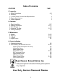
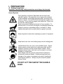
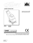
OWNERS MANUAL Small Concrete Saw MODEL: C1318P FORM <<7317A 3/2011 WARRANTY Norton warrants all products manufactured by it against defects in workmanship or materials for a period of one (1) year from the date of shipment to the customer. The responsibility of Norton under this warranty is limited to replacement or repair of defective parts at Norton's Gainesville, Georgia factory, or at a point designated by it, of such part as shall appear to us upon inspection at such point, to have been defective in material or workmanship, with expense for transportation borne by the customer. In no event shall Norton be liable for consequential or incidental damages arising out of the failure of any product to operate properly. Integral units such as gasoline engines, electric motors, batteries, tires, transmissions, etc., are excluded from this warranty and are subject to the prime manufacturer's warranty. This warranty is in lieu of all other warranties, expressed or implied, and all such other warranties are hereby disclaimed. Important: Before placing equipment in operation, record the following information. MODEL:_________ SERIAL NO.___________ PURCHASE FROM: _____________________ ADDRESS: ____________________________ CITY_______ STATE ______ ZIP ________ TELEPHONE NO. ______________________ Before using this equipment, make sure that any person using it reads and understands the instructions in this owner’s manual. 2 Table of Contents CONTENTS PAGE I. Preparation A. Safety Precautions B. Assembly C. C1318P Series Concrete Saw Specifications D. Engine Specifications E. Pointer Alignment 4-6 7 8 9 9 II. Operation A. Blade Installation B. Starting The Engine C. Water Supply D. Operating The Saw E. Cutting Technique 9-10 10-11 12 12-13 13 III. Maintenance A. Engine B. Bearings C. V-Belts D. Depth Control 14-15 15-16 16-20 21 IV. Parts List Section A. Ordering Information B. Parts Drawing and Service Parts List Depth Control And Depth Lock Group Handle Bar Group Blade Guard Group Blade Shaft Group Belt Tensioning Group Engine Mount Group Main Frame Group Water Control Group Front Pointer Group 22 23-33 23 24 25 26-27 28 29 30 31-32 33 Read Owners Manual Before Use Safety Alert Symbol: Information Following This Symbol Is Very Important. Use Only Norton Diamond Blades 3 I. PREPARATION A. Safety Precautions Important! The following safety precautions must always be observed. Hazard Symbols Fuel (gasoline) is extremely flammable and its vapors can explode if ignited. Store gasoline only in approved containers, in well-ventilated, unoccupied approved areas, and away from sparks or flames. Do not fill the fuel tank while the engine is hot or running. Do not start the engine near spilled fuel. Never use the fuel as a cleaning agent Engine components can get extremely hot from operation. To prevent burns, do not touch the engine or related parts while the engine is running or immediately after it is turned off. Never operate the engine with any heat shields or guards removed. Keep all guards in place when operating any piece of equipment Keep hands, feet, hair, and clothing away from all rotating parts Lethal Exhaust Gas: use only in well ventilated areas. Engine exhaust gases contain poisonous carbon monoxide, which is odorless, colorless, and can cause death if inhaled. Avoid inhaling exhaust fumes, and never run the engine in a closed building or confined area. Never tamper with the governor components of settings to increase the maximum speed. Severe personal injury and damage to the engine or equipment can result if operated at speed above maximum. Always obey the maximum speed rating of blade. DO NOT LIFT THE SAW BY THE HANDLE BARS 4 Dust and Silica Warning Grinding/cutting/drilling of masonry, concrete, metal and other materials can generate dust, mists and fumes containing chemicals known to cause serious or fatal injury or illness, such as respiratory disease, cancer, birth defects or other reproductive harm. If you are unfamiliar with the risks associated with the particular process and/or material being cut or the composition of the tool being used, review the material safety data sheet and/or consult your employer, the material manufacturer/supplier, governmental agencies such as OSHA and NIOSH and other sources on hazardous materials and make certain to comply with all product warnings and instructions for the safe and effective use of the material being cut. California and some other authorities, for instance, have published lists of substances known to cause cancer, reproductive toxicity, or other harmful effects. Control dust, mist and fumes at the source where possible. In this regard use good work practices and follow the recommendations of the manufacturer/supplier, OSHA/NIOSH, and occupational and trade associations. Water should be used for dust suppression when wet cutting is feasible. When the hazards from inhalation of dust, mists and fumes cannot be eliminated through engineering controls such as vacuum and/or water mist, the operator and any bystanders should always wear a respirator approved by NIOSH/MSHA for the material being cut. Use Approved: Eye Protection Hearing Protection Respiratory Protection 5 Head Protection 1. Before mounting any blade on the saw, the blade should be inspected for any damage which might have occurred during shipment, handling or previous use. 2. The blade collars and arbors should be cleaned and examined for damage before mounting the blade. 3. The blade must be properly fitted over the arbor with the drive pin on the outside collar projecting through the drive pin hole on the blade and inside collar. 4. The blade shaft nut, which is a left-hand thread nut, must be tightened securely against the outside blade shaft collar. 5. The blade must be operated within the specified maximum operating speed listed on the blade. 6. Turn water control valve to full to provide adequate coolant (4 to 6 gallons per minute) for diamond blades and wet cutting abrasive blades. Insufficient coolant could result in severe blade breakage or diamond segment separation. 7. The blade guard must be in place with the nose guard down and locked when the saw is running. 8. The operator should wear safety glasses and any other appropriate safety equipment. 9. When starting the saw, the operator should stand away and to the side of the blade. 10. If for any reason the saw should stall in the cut, raise the blade out of the cut. Check the outside blade shaft collar and nut for tightness. Inspect the blade for damage before restarting the saw. Use caution when resuming a cut. Be certain that the blade is in alignment with the previous cut. 11. During cutting operations do not exert excess side pressure on the handles as a method of steering. Do not force the blade into the cut by lowering the blade too fast or by pushing the saw too fast. You Are Responsible For Your Safety!!! 6 I. PREPARATION B. Assembly The compact concrete saws are shipped completely assembled and ready for use except for diamond blade, gasoline, oil, and handle bar. Inspect the saw for shipping damage. If any damage is found, contact the shipper immediately and file a freight claim. Norton Clipper is not responsible for any freight-related damages. Remove the saw from the pallet. Reverse the position of the handlebars so that the handle bar sticks out towards the operator. Adjust the handlebars to the desired height. Align the hole located in the operator’s right side of the Handle Bar Assembly with the M10 Weld Nut in the frame. Attach the handlebars to the saw with the supplied hardware. The Operator’s Right Side Screw part# 028098 will pass through a hole in the Handle Bar Assembly. Tighten 029098 to the Handle Bar Assembly and then tighten the M10 Jam Nut 027006. Tighten 027021 to the Handle Bar Assembly and then tighten the M10 Jam Nut 027006. Read and understand the remaining sections of this Owners Manual. NOTE: Do not install the blade until it is time to use the saw. ANSI regulations prohibit the transportation of any concrete saw with the blade installed. DO NOT LIFT THE SAW BY THE HANDLE BARS M10 Weld Nut 027006 027021 027006 028098 Part # 027021 028098 027006 Description Screw DIN931 M10 x 25 Hex Head Cap Screw DIN933 M10 x 65 Hex Head Cap M10 Jam Nut DIN934 7 QTY 1 1 2 C. C1318P Series Concrete Saw Specifications Dimensions/Weight Length (Working) Length (Transport) Width Height Weight Engine Engine Mfg. Spec No. Engine Type Horse Power - Gross Max Torque – Gross Model Model Cooling System Oil Capacity Fuel Capacity Fuel Type Low Oil Sensor Air Filtration Characteristics Max Blade Depth of Cut 18” (406 mm) 16” (406 mm) 14” (356 mm) 12” (305 mm) Arbor Bore Blade Shaft Locking Device Blade Shaft Speed Depth Control Depth Lock Depth Gauge Number Of Belts Blade Guard Type Right or Left Side Cutting Lifting Bale Handle Bars Water Tank Water Tank Capacity Water Hose Connector Recessed Rear Wheels Sound pressure1 Sound power1 Vibration emission value 45.66” (1160 mm) 33.50” (850 mm) 39.50” (1003 mm) 39” (990 mm) 220 lbs (100 kg) Honda GX390K1QXC9 Single Cylinder 4 Cycle 13 hp* (9.5kW) @ 3,600 rpm 19.5 ft-lbs (26.5 Nm, 2.7 kg-m) @ 2,500 rpm GX390K1QXC9 GX390 Air 1.16 US qt (1.1 liter) 1.79 US gal (6.5 liter) Unleaded Gasoline (86 pump octane) Yes Four Stage Cyclone 18” (450 mm) 6.75” (172 mm) 5.75” (146 mm) 4.75” (121 mm) 3.75” (95 mm) 1” (25.4 mm) Machined Into Flats Of Tight Collar 2,573 rpm Hand Wheel With Screw Feed Standard Customer Installed Accessory Single Ten (10) Groove K Section Belt Hinged, All Steel Construction Yes Built In Adjustable, Stays Level At All Times Standard 6.5 US Gallons (24.6 liter) Standard Garden Hose With Flow Control Valve Standard 88 db(A) 105 db(A) 9.18 ft/ s² (2.8 m/s²) (according to EN 12096) * = Horse power and Torque ratings are Gross Horse power and are supplied by the engine manufacturer. Actual output of the engine will vary due to many factors including operational speed of engine, environmental conditions, maintenance, fuel, and other variables. Saint-Gobain Abrasives, Inc. makes NO claim to actual or gross horse power and torque ratings. 1) The sound measures have been made following pr EN 12638, Annex A; 2)“Floor sawing, grooving and milling machines – Safety “ 8 D. Engine Prior to attempting to operate the engine, read the information contained in the engine owner's manual. An engine owner’s manual is supplied with every gasoline powered concrete saw. 1. Check Oil: Add oil if low. Refer to the engine owner's manual for the recommended SAE viscosity grades. Capacity of oil is 1.16 US quarts (1.1 liters) 2. Check Fuel: Fill if low. Use only unleaded gasoline with a pump sticker octane rating of 86 or higher is recommended. Never use an oil and gasoline mixture! 3. Air Cleaner: Never run the engine without the air cleaner! Rapid engine wear will result from contaminants being drawn through the carburetor and into the engine. 4. Engine Starting: Refer to the engine owner's manual additional proper engine starting procedure. E. Pointer Alignment 1. Use a straight edge, and carefully mark a line 12 feet long on a smooth level surface. 2. Place the saw blade on the marked line, move the saw to the center of the marked line and then lower the blade until it is about 1/16” above the marked line 3. Measure from each end of the saw frame to insure that the frame is parallel to the marked line. Adjust the saw as needed. 4. With the blade centered on the marked line and the saw frame parallel to the marked line, lower the front pointer. 5. Adjust the pointer by bending it until is aligned with the marked line. II. OPERATION A. Installing the Blade 1. Disconnect the spark plug. 2. Remove the blade shaft nut, (Turn clockwise), and remove the outside collar. 9 3. Clean off any foreign particles on the clamping surfaces of both collars and on the mounting surface of the blade. 4. Place the blade on the blade shaft, lining up the drive pin hole in the blade with the drive pinhole in the inside collar. For Best Performance Use Only Norton Diamond Blades Specified For the Material Being Cut. 5. Slide the outside blade shaft collar onto the blade shaft. The drive pin on the outside collar must project through the drive pin hole in the blade and into the inside collar. 6. Tighten the blade shaft nut (counter-clockwise) securely against the outside collar. 7. Reconnect the spark plug. B. Starting the Engine 1. Refer to the engine owner's manual for detail starting procedures. 2. Always cut with engine rpm in the full throttle setting. Before starting, insure that the blade is properly installed, all guards are in place and in safe operating condition, and that the Blade is not in contact with any surface or object. Also verify that the area where the work is to be preformed is clean, safe, and has proper ventilation and lighting. Always located and properly mark all water, gas, and electrical services before beginning any work. 10 Turn the Fuel Control To the ON Position Move the choke lever to the CLOSED position. NOTE: do not use the choke if the engine is warm or the air temperature is high. Pull The Throttle Control Slightly to the Rear to provide some engine throttle. Place the engine ON/OFF switch to the ON position Pull the starter grip lightly until you feel resistance, then pull briskly. CAUTION: Do not allow the starter grip to snap back against the engine. Return it gently to prevent damage to the starter. As the engine warms up, gradually move the choke lever to the OPEN position. Position the throttle control lever for the maximum engine speed (full Rear). To stop the engine, move the Throttle Control Lever fully to the Forward Position (Slow) right, then turn the engine switch to the OFF position. Turn the fuel valve to the OFF position. Never transport the machine with the Fuel Valve in the ON position. Never Store the machine with the Fuel Valve in the ON position. Never Transport a machine with the blade installed. 11 C. Water Supply Pressurized source: Turn the water control to full "ON" when using wet cutting blades. The required flow rate is 4-6 gallons per minute. Water Tank on saw: This supply is designed for use with dry blades to keep the dust levels down. The tank will not supply the proper water flow rates when used with wet cut only blades. Do not drink the water from this tank. Fill the tank with water only. Close the water tank valve. Attach the saws water supply hose to the tank outlet. Fill the tank with water. The capacity of the tank is 6.5 US Gallons (24.6 liter). When you are ready to cut, adjust the water supply rate until a fine mist or a slow trickle is made. The use of water greatly decreases the amount of dust produced during the cutting process, aids in the cooling of the blade, and provides additional stability. Use Only Water In The Water Tank Do Not Drink From The Tank D. Operating the Saw 1. For blade installation instructions see section II. Operation sub heading A. Installing the Blade. For the engine starting instructions, see the Engine manual and follow the instructions located in section II. Operation sub heading B. Starting the Engine. 2. Check the Engine Oil level. 3. Raise the saw to the full upright position. Do not let the blade come in contact with the ground. 4. Maneuver the saw to the desired starting point. 5. If wet cutting, connect the water supply to the saw. 6. Follow the instructions for starting the engine found in the Engine manual. 7. If wet cutting, turn on the water supply at the source and then open the water valves on the saw. Make sure that there is a minimum of 4-6 gallons per minute of water flow!! 8. Be sure the engine is running at full throttle!!! 9. Slowly lower the blade by rotating the hand wheel clockwise until the desired depth of cut is reached. Use a reasonable rate of feed. Do not force the blade into the cut!! 12 10. When the end of the cut is reached, slowly raise the blade out of the cut by rotating the Hand Wheel counter-clockwise until the blade is at least one (1) inch above the ground. 11. Only move the saw in reverse with the blade in the raised position. 13. When moving the saw to a new location, be sure the blade is not touching the ground. Always pay close attention to where you are moving and where the blade is at all times. E. Cutting Technique Lower the blade into the concrete to the required depth by turning the hand wheel clockwise. Reduce the forward pressure if the saw begins to stall. Note: For deeper cuts (4 inches or more), several cuts should be made in incremental steps of 1-1/2 to 2 inches until the desired depth of cut is reached. Push the saw steadily forward using the front pointer as a guide. Exert enough forward pressure so that the engine begins to labor, but does not slow down. If the saw begins to stall, reduce the forward movement until full rpm is restored to the blade. If the saw stalls, raise the blade out of the cut before restarting. Avoid excessive side pressure or twisting of the blade in the cut. Additional Guide Lines For Sawing: Understand and follow all of the instructions in this owner’s manual. If wet cutting, turn on the water supply so that there is a minimum of 4-6 gallons per minute of water flow!! In critically hard aggregate, more than a single pass may be needed to cut the desired depth. If the saw stalls in the cut, immediately stop the forward speed and raise the blade out of the cut. If this is not done the belts can fail or the blade may be damaged. Go slowly with a new blade until it opens up, that is, until the diamonds can be seen and felt. 13 III. MAINTENANCE A. Engine Follow the below schedule for engine maintenance. NOTE: Check the Honda Engine manual that came with the engine for any changes to the maintenance schedule. If the charts have any differences, follow the chart in the Honda Engine Manual. The Norton does not warranty the engine. If any warranty or service of the engine is required contact your nearest Honda service center, or from the Internet: http://www.honda-engines.com/home.htm Honda engine (refer to owner's manual for complete maintenance.) Check the engine oil level before each use when the engine is cool and the engine is level. Add oil if the level is low. The oil level should be within the operating range (see the engine owner’s manual for details). Only use a high-detergent, premium quality motor oil certified to meet or exceed U.S. automobile manufacturer’s requirements for Service Classification SG, SF/CC, CD. Motor oils will show the classification on the container. A SAE viscosity of 10W-30 is recommend by Honda for general, all temperature use. Please consult the below chart or contact your local Honda service center for the proper viscosity for your temperature range. 14 Always refer to the engine manual for more detailed information on checking the oil, changing oil, and oil capacity, air filter changes, and fuel type to use. Use only Honda air filters. Do not clean the air filter with gasoline or other flammable solvents. A fire or explosion could result. To clean, follow the instructions found in the Honda engine manual. Dry Cutting Engine Maintenance When operating the engine in dry cutting or dusty environments the following is required: Engine oil changed more often. Every 50 hours (or more often if conditions require) clean all of the engine cooling fins. Every 25 hours (or more often if conditions require) clean the engine precleaner. Every 100 hours (or more often if conditions require) replace the air filter. If the engine is equipped with a reusable air cleaner, clean and re-oil it. Check and clean the air filter after each use. Replace as needed. B. Bearings Re lubrication type bearings must be relubricated weekly to assure long life. The grease used should conform to the NLGI grade two and be free of any chemical impurities such as free acid or free alkali, dust, rust, metal particles or abrasives. 15 For best results, bearings should be relubricated while in operation. Note: Due caution for personal safety must be observed when servicing rotating equipment. The grease should be pumped in slowly until a slight bead forms around the seals. This bead, in addition to acting as an indicator of adequate relubrication, provides additional protection against the entry of foreign matter. If necessary to relubricate while the bearing is idle refer to relubrication table for maximum grease capacity for the various size bearings. Shaft Size Maximum Grease Capacity of Bearing Chamber in Ounces 1/8 3/8 5/8 1/2"' to 3/4" 7/8" to 1-3/16" 1-1/4" to 1-1/2" Improper Maintenance Of Bearings Is Not Covered By Any Warranty. Over Lubrication Will Damage A Bearing. Grease Protruding From The Sides Of The Bearing Is A Sign Of Over Lubrication. Not Lubricating Bearings Will Damage The Bearing Unit. Damage Caused By Over or Under Lubricating Bearings Is Not Covered By Any Warranty. C. V-Belts Warning: Never make adjustments to belts or pulleys while engine is running! The best tension for a belt drive is the lowest tension at which the belts will not slip under full load. To adjust the C1318P Belt Tension: The C1318P uses a simple single point tensioning system for the belt tensioning. The Belt Tensioning Assembly can be found behind the engine and is located in the center of the Frame. The Belt Tensioning Device is designed to pull or push the engine from the center which helps to reduce the Engine from twisting during the Belt Tensioning process. This new system is designed to be simple to install and to maintain with the tools equipped with the machine. Insure that the Engine ON/OFF Switch is in the OFF position and that the Spark Plug is disconnected before making any adjustment to the Belt tension. 16 Engine M10 Mounting Bolt, qty =4. Note one (1) per corner of engine. Belt Guard Belt Tensioning Assembly M10 Belt Guard Retaining Hardware, qty=3. NOTE: One (1) Bolt is on the front of the Belt Guard Figure: C1318P Belt Tensioning System 1. Review the locations of the C1318P Belt Tensioning system before proceeding. (See Figure: C1318P Belt Tensioning System on the previous page). 2. Remove the Belt Guard by loosening and removing the three M10 Belt Guard Retaining Bolts. 3. Check belt tension by pushing up or down at the center top span of the belt. The belt should move around 3/8” to ½” up and down. If adjustment is needed go to step 4. If no adjustment is required, replace belt guard and tighten all of the M10 Belt Guard Retaining Hardware. 4. Loosen the four (4) M10 Engine Mounting Bolts. 5. Loosen the two (2) M10 Jam Nuts on the C1318P Belt Tensioning Assembly (See Figure: C1318P Belt Tensioning Assembly below). 17 M10 Jam Nut M10 Jam Nut Figure: C1318P Belt Tensioning Assembly 6. To apply tension to the Belts tighten (turn clockwise) the rear M10 Jam Nut until the required Belt Tension is achieved. To loosen the Belts turn the front M10 Jam Nut counter clockwise until the required Belt Tension is achieved. (See Figure: C1318P Belt Tensioning Jam Nut Directions). NOTE: Do not over tighten the belts as too tight of belts can break Engine Output Shafts, Blade Shafts, Belts, and cause premature Bearing Failures. Failures due to too tight of Belts are not covered by any warranty. Too loose of Belts will cause the Belts to slip under load, and may cause burning of the Belts and is not covered under any warranty. Figure: C1318P Belt Tensioning Jam Nut Directions 18 7. Tighten the four (4) M10 Engine Mounting Bolts. 8. Replace the Belt Guard and replace and tighten the M10 Belt Guard Retaining Hardware. 9. Run the machine for around 15 minutes and recheck the belt tension. If the Belts slip under load increase the belt tension. Remember, too much tension shortens belt and bearing life! Check the belt tension frequently during the first day of operation. Check the belt tension periodically thereafter and make any necessary adjustments. To align the Pulleys: 1. Review the locations of the C1318P Belt Tensioning system before proceeding. (See Figure: C1318P Belt Tensioning System on page 15). 2. Remove the Belt Guard by loosening and removing the three M10 Belt Guard Retaining Bolts. 3. Line up a straight edge along the out side face of both pulleys. (See Figure: Pulley Alignment to the right.) 4. Misalignment will show up as a gap between the pulley face and the straight edge. 5. To correct the misalignment move one pulley in or out as required. Main Causes of Belt Failures: Figure: Pulley Alignment Premature Belt failure can be attributed to the following issues: Tension (too much or too little), Pulley Misalignment, Damaged Pulleys, Improper Handling or Storage, Incorrect Blade Specification for Material Being Cut, and Cutting Too Deep. Symptom Possible Cause Too Much Tension Corrective Action Re-tension Belts Belt Breakage Excessive Shock Load Pulley Out Of Round Reduce Load/ Check Blade Specification Replace Pulley Too Little Belt Tension Increase Belt Tension Excessive Load (Cutting Full Depth) Containments On Belts For Best Performance Only Cut only 1-/2” to 2” Per Pass Replace Belts and Find Source Of Containments Replace Blade With One Designed For Material Being Cut Burning of Belt Incorrect Blade Specification 19 Belt Failure Table Continued From Previous Page Symptom Belt Tearing/Ripping Belt Rolling Off Pulley Belt Cracking Possible Cause Pulley Misalignment Pulley Misalignment Extremely Low Temperature at Startup Corrective Action Align Pulleys Align Pulleys Warm Machine Before Use Exposure To Chemicals or Lubricates Locate Source of Containments and Replace Belts. Belts are a normal wear item and are not covered under warranty. 20 D. Depth Control The depth control (raising screw) consists of a threaded rod, which feeds into a steel nut. In order to keep the two parts working smoothly it is necessary to keep the rod free from dirt and sludge as much as possible. Cleaning the threaded rod with a rag after each use will prevent sludge from collecting in the tube assembly and protect the threads. It is a good practice to keep the raising screw threads lubricated, as the slurry generated during cutting will cause premature thread wear. The bearing used to support the raising screw should be checked after each use to make sure it is turning freely and lubricated. If the bearing requires re lubrication lithium base grease is recommended. F. Inspections and Cleaning X X X X X X X X X X X X X Inspect Inspect After Damage X End Of Day X After Failure Blade Collars Belt Tension Water Hose, Water Fittings, and Nozzles Depth Screw Engine Reachable Hardware Bearings (Blade Shaft and Depth Control) Wheels Handle Bar Vibration Reduction System Inspect For Damaged or Missing Components Clean Clean Check Clean Inspect Grease Clean Tighten Grease* Once A Week Whole Machine → During Blade Change At Every Indicated Period Beginning Of Day Regular Service Period Preformed After First Hour of Work For long life and better machine performance follow the inspection and cleaning schedule below. X X X X X X X X X X X X X X * = See Bearing Maintenance of This Manual Before Greasing Replace any damaged or missing components before using machine. 21 IV. PARTS LIST SECTION A. Ordering Information 1. List model number and serial number of machine from the Machine’s Serial Number Plate. 2. List part number, UPC number, and Description of part DO NOT use the item number. 3. Wherever alternate parts are shown due to product improvement, inspect the part you have and provide additional description as necessary. 4. Specify mode of shipping desired, such as, parcel post, truck, U.P.S., best way, etc. For the nearest Norton Clipper distributor call 254-918-2310 Common Replacement Parts Description BELT Poly-V 10 PK 698MM Blade Shaft Nut ¾-16 Left Hand Thread (Operators Right Side Of Saw) Blade Shaft Nut ¾-16 Right Hand Thread (Operators Left Side Of Saw) Collar Tight (Operators Right Side) Collar Tight (Operators Left Side) Collar Loose Assembly (With Pin) Drive Pin 3/8 x 1 Water Tank Complete C1318P/CS451 Bearing Blade Shaft W/Hardware (1) Front Wheel Complete W/Hardware (1) Rear Wheel (1) Wrench 1-1/2” Wrench 32mm Wrench 17mm Part Number 232344 UPC 70184643371 227156 70184673903 227191 70184674346 227159 227190 227247 227154 232356 72474 82786 80991 105377 82910 72279 70184673904 70184674352 70184674082 70184674556 00310351798 00310004295 00310006552 00310005495 70184649317 70184681049 70184655806 NOTE: All Parts Are Sold As Individual (each) Unless Noted Otherwise Blades Use Only Clipper Diamond Blades. Contact your local Norton Clipper Distributor or our Customer Service at 254-918-2310 for the best blade for the application. All parts are designated as either Service Parts (S) or Wear Parts (W) in the Type column in the parts listing. Wear parts are worn out through normal use of the machine. The wear period depends on the intensity of use of the machine, handling, and maintenance of the machine. Wear parts must be serviced and eventually changed following the indications of the manufacturer. Any wear due to normal use of the machine will not be considered as a case of warranty for items designated as Wear Parts (W). For best performance and life Genuine Norton Clipper replacement parts should always be used. Changes to part specifications, are subject to change with out notice. 22 Depth Control and Depth Lock Group 2 1 8 7 6 4 5 Front Of Machine Item 1 2 3 4 5 Part No 076465 076843 048620 232349 082787 UPC No 00310002163 00310004966 70184643370 00310327609 00310006553 6 082788 00310006554 7 082789 00310006555 8 Description HANDWHEEL AND HANDLE NUT HANDWHEEL SPACER 28x22x22 WHEEL HOOK + SPRING CS 501 TUBE DEPTH CTRL W/HARDWARE RAISE SCREW C13/C13P18/C1318P RING STOP DEPTH CONTROL QTY 1 1 1 1 1 Type S S S S S 1 S S NOTES Includes: Handle and Hardware Includes: Acorn Nut, and Washers Includes: Hook, Spring, and Nut Includes: Depth Tube and Hardware Includes: Raise Screw and Key Includes: Set Collar and Set Screw 1 BEARING FLG KIT DEPTH 1 W CONTROL Includes: Bearing and Hardware Type: S = Service Part, W = Wear Part, All Parts Are Sold As Individual (each) Unless Noted Otherwise 076670 00310004907 23 Handle Bar Group 4 Item Part No UPC No 1 232313 70184643284 2 072097 00310004190 3 4 5 6 027021 027006 232368 232350 70184600809 70184681615 70184643256 00310353381 Description QTY Type HANDLE BAR ASSEMBLY C1318P 1 S GRIP HANDLE 2 S NOTES Includes: Handle Bar Frame (Upper and Lower), Hand Grips (2), Vibration Absorber Kit (4), and Hardware Sold As Each. Appearance May Vary SCR M10 X 25 8.8 DIN933 1 S NUT M10 1.5 DIN934 2 S SCR M10 X 70 1.5 DIN933 1 S VIBRATION ABSORBER KIT (4) 1 W Includes: Set of Four (4) Silent C1318P Bock and Mounting Hardware Type: S = Service Part, W = Wear Part, All Parts Are Sold As Individual (each) Unless Noted Otherwise NOTE: In order for the Vibration Reduction System to function properly the Acorn Nuts towards the operator are torque to 0.27 lb-feet (4Nm). The Acorn Nuts on the bottom of the handle bars are fully tightened. Over tightening of the Operator Size Acorn Nuts will prevent the Vibration Reduction System from functioning. 24 Blade Guard Group 10 2 Front Of Machine Item 1 Part No 232317 UPC No 70184643285 2 3 4 5 6 238222 238223 238224 238225 082800 70184628500 70184628501 70184628499 70184628498 00310006566 7 8 9 10 11 083366 232351 083367 9600010 072286 00310007020 70184643255 00310007021 70184650463 00310004233 12 Description BLADE GUARD ASSEMBLY C1318P PIN GUARD LOCK RING GUARD LOCK SPRING GUARD LOCK GUARD LOCK GUARD SPLASH KIT QTY 1 Type S 2 2 2 2 1 S S W S W NOTES Includes: Items 2 (2x), 3 (2x), 4 (2x), 5 (2x), 6, 7. 8, and 9 Includes: Splash Guard and Hardware NUT HEX M15 X 38MM 1 S WASHER M16 FENDER DIN9021 1 S BOLT BLADE GUARD 1 S FIT BARB HOSE 1/4MPTX3/8 1 S FIT HOSE Y 1 S NOZZEL WATER (2) 082998 70184681299 C13/C1318P/C1318P/C13E/C9E 1 S Set of two (2) Nozzles Type: S = Service Part, W = Wear Part, All Parts Are Sold As Individual (each) Unless Noted Otherwise 25 Blade Shaft Group 7 Front Of Machine 26 Blade Shaft Group Item 1 Part No 232352 UPC No 70184643291 Description PULLEY ENGINE KIT C1318P QTY 1 Type S 2 232344 70184643371 BELT POLY-V 10 PK 698MM 1 W 3 232357 70184643372 1 S 70184673903 SHAFT BLADE ASSEMBLY C1318P NUT BLADE SHAFT 3/4-16 LH 4 227156 1 S 5 -NA6 227247 227154 227190 70184674082 70184674556 70184674352 ASSY OUTER FLANGE (LOOSE) PIN DRIVE (GROOVED) 3/8X1 COLLAR TIGHT LEFT SIDE RH 2 2 1 S W S 7 232353 70184643373 1 S 8 9 083421 072474 00310007070 00310004295 1 2 S W 10 227159 70184673904 PULLEY BLADE SHAFT KIT C1318P BLADE SHAFT C13P18/C1318P BEARING BLADE SHAFT (1) W/HARDWARE COLLAR TIGHT RIGHT SIDE LH 1 S 11 227156 70184673903 NUT BLADE SHAFT 3/4-16 LH 1 S 12 238057 70184628179 13 N/A NOTES Includes: Pulley, Bushing, Set Screws, and Key Includes: Items 4, 5 (2x), 6, 7, 8, 9 (2x), 10, and 11 NOTE: Does Not Include Belt Operator's Left Side - Right Hand Thread Includes: Collar and Drive Pin Operator's Left Side - Right Hand Thread Includes: Pulley, Bushing, Set Screws, and Key Blade Shaft Only Includes: One (1) Bearing, and Hardware Operator's Right Side - Left Hand Thread Operator's Right Side - Left Hand Thread OIL DRAIN HOSE ASSY 13HP 1 S HONDA 123327 70184671620 ENG 13HP HONDA 1 S Engine Only GX390K1QXC9 123328 70184676096 AIR FILTER HONDA 11-13HP 1 W Type: S = Service Part, W = Wear Part, All Parts Are Sold As Individual (each) Unless Noted Otherwise 27 Belt Tensioning Group Item 1 Part No 232330 UPC No 70184643374 Description QTY Type NOTES ENGINE MOUNTING KIT 1 S Includes: Front, Rear Motor W/HARDWARE C1318P Mounts, and Hardware Type: S = Service Part, W = Wear Part, All Parts Are Sold As Individual (each) Unless Noted Otherwise 28 Engine Mount Group 1 6 Front Of Machine Item 1 Part No 083371 UPC No 00310007025 Description GUARD BELT ASSY 2 232358 70184643375 3 083369 00310007023 4 5 082804 082802 00310006570 00310006568 BLADE SHAFT GUARD ASSMEBLY C1318 FRAME WELD MOTOR C13P18/C1318P BRAKE KIT REAR WHEEL C13P18/C1318P PIVOT MOTOR & FRAME KIT 6 7 8 9 10 11 227146 70184674553 PIN COTTER 1/8 X 1-1/2 2 W 080999 00310005502 BUSH OUTR MOT PIVOT (1) 2 W 080297 00310005129 BUSH INNR MOT PIVOT (2) 2 W Sold In Set Of Two (2) 082803 00310006569 PIVOT MOTOR & FRAME 1 S Engine Mount Pivot Shaft Only 27030A 70184681620 SCR M10 X 35 1.5 DIN933 1 S 27006 70184681615 NUT M10 1.5 DIN934 1 S Type: S = Service Part, W = Wear Part, All Parts Are Sold As Individual (each) Unless Noted Otherwise 29 QTY 1 Type S NOTES Includes: Belt Guard and Hardware Includes: Blade Shaft Guard and Hardware 1 S 1 S Includes: Engine Mount Only 1 1 S W Includes: Break and Hardware Includes Items: 6 (2x), 7 (2x), 8 (2x). 9 (2x) Main Frame Group 13 3 Front Of Machine Item 1 Part No 232323 UPC No 70184643376 2 3 4 5 6 082784 080297 080999 27504B 080991 00310006550 00310005129 00310005502 70184681623 00310005495 7 8 9 10 11 12 13 14 15 Description MAIN FRAME WELDMENT C318P QTY 1 Type S NOTES Frame Only Includes Items: 3 (2x), 4 (2x), 5 (6x), 6 (2x), 7 (2x), and 11 Sold In Set Of Two (2) AXLE REAR COMPLT W/WHEELS 1 S BUSH INNR MOT PIVOT (2) 2 W BUSH OUTR MOT PIVOT (1) C 4 W WASHER M20 DIN125 FLAT 6 S WHEEL 200X50X100 (20mm Bore) 2 W REAR 227146 70184674553 PIN COTTER 1/8 X 1-1/2 1 W 27030A 70184681620 SCR M10 X 35 1.5 DIN933 2 S 27006 70184681615 NUT M10 1.5 DIN934 2 S 082786 00310006552 WHEEL FRONT KIT 125/50/20 2 W Includes: Wheel and Hardware 082785 00310006551 AXLE REAR ONLY 1 S C13/C13P18/C1318P 227115 70184674394 SWITCH ENGINE ON/OFF HONDA 1 W Sold as Each For GX390K1QXC 232124 00310024052 THROTTLE ASSEMBLY 1 W Includes: Throttle Control, Control C13P18/C1318P Cable, and Hardware 224237 70184665412 SCR M6 X 20 1.0 DIN933 1 S 300833 70184625661 NUT M6 1.0 DIN934 HEX 1 S Type: S = Service Part, W = Wear Part, All Parts Are Sold As Individual (each) Unless Noted Otherwise 30 Water Control Group 13 Front Of Machine 31 Water Control Group Item Part No UPC No 1 232356 00310351798 2 082794 00310006560 Description WATER TANK COMPLETE C1318P/CS451 STOPPER WATER TANK C13/C13P18/C1318P QTY Type 1 S 1 S NOTES Includes: Water Tank and Stopper (Cap) Includes: Valve Assembly w/Hose Adapter (1), Male Quick Detach x 3/4" Garden Hose (1), Female Quick Detach (1) x ¾” Garden Hose, Hex Bushing 3/4" Garden Hose x 1/2 FPT (1), and Reducing Bushing 1/2 MPT x 1/4MPT (1) 3 4 5 6 7 8 9 10 11 12 13 232121 9600010 072286 NOTE: Valve Assembly w/ Hose Adapter, Male Quick Detach x ¾” Garden Hose, and Female Quick Detach x ¾” Garden Hose are not sold separately 00310024053 70184650463 00310004233 VALVE & CONNECTOR ASSY 1 S FIT BARB HOSE 1/4MPTX3/8 1 S FIT HOSE Y 1 S NOZZEL WATER (2) 082998 70184681299 C13P18/C1318P 1 S Set of two (2) Nozzles CLAMP HOSE WORM 7/32"TO 5/8 227126 70184674516 x 5/16"W 1 S 200195 70184627867 HOSE 3/8"ID X 1/2"OD X 48"LG 1 S 238067 70184628020 REDUCER FIT 3/4MGH x 1/2FMPT 1 S 232354 70184643377 BUSHING HEX 1/2MPT x 3/8 FPT 1 S 232355 70184643378 NUT PIPE LOCK 3/8 BRASS 2 S 101868 70184650620 WASHER HOSE 1.00OD X .625 1 W 121273 70184650637 SWIVEL HOSE 3/8MPTX3/4GHT 1 S Does Not Include Hose Washer Type: S = Service Part, W = Wear Part, All Parts Are Sold As Individual (each) Unless Noted Otherwise 32 Front Pointer Group Front Of Machine Item Part No UPC No 1 232127 00310024051 2 232126 00310004622 3 4 5 6 7 8 Description POINTER ASSY C13PC18/C13P18/C1318P QTY Type 1 S NOTES Includes: Front Pointer Rod, Pointer Frame, Wheel, and Hardware WHEEL POINTER W/HARDWARE 1 S C13P18/C1318P Front Wheel and Hardware POINTER ROD 232125 00310004244 C13P18/C1318P/C13SP18 1 W Front Pointer Rod Only 237242 70184627482 SCR M10 X 50 1.5 DIN933 1 S Sold as Each 27006 70184681615 NUT M10 1.5 DIN934 1 S Sold as Each 27030 70184681605 SCR M10 X 30 1.5 DIN933 2 S Sold as Each 27504 70184681610 WASHER M10 DIN125 6 S Sold as Each 239007 70184628215 NUT M10 1.5 DIN985 LOCK 2 S Sold as Each Type: S = Service Part, W = Wear Part, All Parts Are Sold As Individual (each) Unless Noted Otherwise 33 Saint-Gobain Abrasives 2770 West Washington Stephenville, TX 76401 Phone: 254-918-2310 Fax: 254-918-2312 34