1
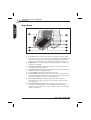
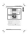
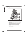
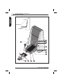
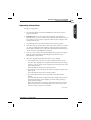
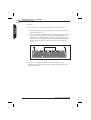
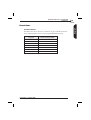
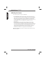
English
User's Guide
Imacon Flextight 848
English
2
© 2002 Imacon A/S. All rights reserved.
Imacon Flextight 848 User's Guide, Part No 70030013, revision C.
The information in this manual is furnished for informational use only, is subject to change
without notice, and should not be construed as a commitment by Imacon A/S.
Imacon A/S assumes no responsibility or liability for any errors or inaccuracies that may
appear in this manual.
Imacon A/S assumes no responsibility or liability for loss or damage incurred during or as a
result of using Imacon software or products.
Imacon, FlexColor and Flextight are trademarks of Imacon A/S. Adobe and Adobe Photoshop
are trademarks of Adobe Systems, Inc. Macintosh, Mac OS, FireWire and ColorSync are
registered trademarks of Apple Computer, Inc.
Printed in Denmark.
User's Guide - Flextight 848
Table of Contents
Hardware Reference - Flextight 848
Warnings and Restrictions
System Requirements
Front Panel
Back Panel & Connectors
Cut-Away View
Setting up the Scanner
Environmental Requirements
Electrical Requirements
Installation Procedure, FireWire Interface
Installation Procedure, SCSI Interface
Operating Instructions
Resolutions
True Resolutions
Calibrating the Scanner
Focus Calibration
White Calibration for Reflectives
The Light Tubes
General
Replacing the Light Tubes
Cleaning the External Surface of the Scanner
Disposal
Technical Specifications
FCC Notice
CE - Declaration of conformity
User's Guide - Flextight 848
5
6
7
8
9
10
11
11
11
12
12
15
19
19
20
21
22
25
25
25
27
27
28
29
30
3
English
Table of Contents
Table of Contents
English
4
User's Guide - Flextight 848
Hardware Reference - Flextight
848
This manual provides important information about using your Flextight
848 scanner.
Topics include:
• Important warnings and restrictions
• System requirements
• Diagrams of the front panel, rear panel, and internal structure of the
Flextight 848 scanner
•
•
•
•
•
•
•
•
•
•
Installation instructions
Environmental requirements
Electrical requirements
Operating instructions
Special considerations for scanning 35mm originals
Calibration instructions
Maintenance advice
Disposal instructions
Technical specifications
Declarations of FCC and CE regulation conformity
User's Guide - Flextight 848
5
English
Hardware Reference - Flextight 848
6
Hardware Reference - Flextight 848
Warnings and Restrictions
English
Warnings and Restrictions
• Read all of the included documentation before attempting to install
and use the scanner.
• Do not touch the originals and/or the original holder while scanning.
• Do not start scanning or previewing until an original holder with an
original has been mounted.
• The original holder is only to be mounted or removed when the drum
is in the load position.
• When you turn on the scanner, the drum will roll to the load position,
if it is not there already. Do not touch the scanner while the drum is
rotating.
• Do not place your fingers or any other object into the scanner while it
is connected to power.
• Before servicing or opening the scanner, the power supply must be
disconnected from the mains (unplugged). It is not sufficient simply to
press the on/off button.
• Install the scanner in a location where children can not get to it. It
contains small openings and moving parts that can cause injury.
User's Guide - Flextight 848
Hardware Reference - Flextight 848
System Requirements
7
Below are the basic hardware requirements for the PC or Macintosh
system to which the scanner is to be connected.
For information about the processor, operating system, RAM and
harddisk requirements please refer to the “Software Reference” manual,
that comes with the FlexColor software.
• Screen resolution of 800 x 600 pixels with true colors (24-bits).
• Mouse or other pointing device.
• FireWire interface
or
SCSI Interface
(with Adaptec EZ-SCSI version 4 or later for IBM PC-compatibles
only).
User's Guide - Flextight 848
English
System Requirements
8
Hardware Reference - Flextight 848
Front Panel
English
Front Panel
A
D
E
F
B
G
C
H
Figure 1: Front panel features of Flextight 848
A
B
C
D
E
F
G
H
Feed Table: must be in lower position for normal scanning. When
scanner is not in use you can turn it to upright position flushing with
the scanner front to protect it from dust etc. Adjust to horizontal
position when using the 35 mm slide mount holder (see page 15).
Light Table: for viewing originals. The grid helps you to align your
transparent originals.
Transparency Holder Guide: all transparency holders fit between
two rails to keep them straight.
Original Holder Clasp: all original holders slide into a slot here and
are held in place by a magnetic clasp.
Power Switch: press here to turn the unit on/off.
Power Indicator (Green): Remains lit when ready to scan. Flashes
when first installed to indicate that firmware must be loaded (it will
be loaded automatically when you run FlexColor).
Motor Drive Indicator (Yellow): lights when the scanner is
repositioning the optics to scan in a new format or when drum is
repositioning.
Scan Indicator (Red): lights when scanning. Do not touch the
scanner while this indicator is lit. If the light is flashing when not
scanning, then an error has occurred - please contact your Flextight
dealer for assistance.
User's Guide - Flextight 848
Hardware Reference - Flextight 848
Back Panel & Connectors
9
English
Back Panel & Connectors
5
C
B
D
A
Figure 2: Back panel features of Flextight 848
A
B
C
D
Power Cable Socket: plug the power cable into this socket.
SCSI Port: plug a SCSI cable here and connect it to the previous
SCSI-device in your SCSI-chain or to your computer if no other
devices are connected.
NOTE! The scanner must always be connected as the last device in a
SCSI-chain as the scanner's SCSI interface has an internal active
terminator (see page ).
SCSI Address Selector: assign an address number using the + and buttons. Use only 1, 2, 3, 4, 5, or 6. Do not use 0, 7, 8, or 9.
FireWire Interface Sockets: plug a FireWire cable (max. 6 m) here
and connect it to your computer. You can use the second plug to
connect another device (hard disk, printer etc.) to the FireWire chain.
User's Guide - Flextight 848
10
Hardware Reference - Flextight 848
Cut-Away View
English
Cut-Away View
A
B
C
FLE
XTI
GH
T OR
IGI
NA
D
L HO
LD
ER
PAT
EN
T PE
ND
ING
E
F
G
Figure 3: Cut-away view of Flextight 848
A
B
C
D
E
F
G
CCD Housing: this movable platform contains the light sensor and
holds the optics.
Positioning Lead Screws: for positioning of the CCD housing and
optics housing for the appropriate resolution and original size.
Optics Housing: focuses the image of the original on the CCD.
Upper Light Source: illuminates reflective originals.
Lower Light Source: illuminates transparent originals.
Drum: rotates the original into the scanner and steps it past the CCD
line of focus.
Original Holder: a transparency holder is shown mounted and with
the top layer held open.
User's Guide - Flextight 848
Hardware Reference - Flextight 848
Setting up the Scanner
11
Environmental Requirements
Set up the scanner in a location that fulfils the following requirements:
• Keep the scanner away from sources of heat, such as direct sunlight or
a radiator. Warm temperatures will degrade the quality of your scans for best results, work in a cool environment.
• The scanner must be operated away from sources of strong
electromagnetic interference. Although the scanner complies with all
regulations governing electromagnetic immunity and Imacon has
taken every reasonable step to make the unit immune to
electromagnetic interference, it is still a precision electronic device so
strong radio waves can interfere with your scans.
• The surface on which the scanner is placed must be stable and free
from vibrations. If the scanner is shaken or moved while scanning,
your results may be affected.
• If the scanner has been in a colder environment (e.g. outside or in
storage) just before you set it up in a warmer room, then wait about
two hours before using it - otherwise, condensation may form, which
will prevent the scanner from operating correctly.
• Avoid using the scanner in areas where there is a high level of dust.
Electrical Requirements
The Flextight 848 power supply requires a mains voltage of between 100
and 240 V AC at a frequency of 50 to 60 Hz. This is within the normal
wall-socket power standards of most countries. Do not attempt to use
Flextight 848 with any power source outside the specified range.
The scanner and all devices attached to the scanner (computer, monitor,
FireWire or SCSI devices, etc.) must be grounded (i.e. use a three-point
electrical connection).
Note that the power supply may emit a low hissing sound when plugged
in but not connected to the scanner. This is normal and will not damage
the power supply or scanner.
User's Guide - Flextight 848
English
Setting up the Scanner
12
Hardware Reference - Flextight 848
Setting up the Scanner
English
Installation Procedure, FireWire Interface
1.
Place the scanner on a table near your computer with the front facing
away from you. Make sure that the location you choose meets all
environmental - and electrical requirements as described on page 11.
2.
When using a FireWire interface connection, it is not necessary to
switch of your computer and other connected units. Connect a
FireWire cable from one of the FireWire connectors on your scanner
(see Back Panel & Connectors on page 9) to either the computer's
FireWire connector or to a free FireWire connector on any other
FireWire device already connected to your computer.
3.
Connect the round connector from your power supply to the round
power supply socket on the back of the scanner.
4.
IMPORTANT: Make sure that the wall socket you are planning to
use meets the electrical requirements outlined earlier.
Plug the Flextight 848 power supply into a wall socket. Note that the
power supply may emit a low buzzing sound when plugged in. This
is normal and will not damage the power supply or scanner.
5.
Turn the scanner around so that the front is facing you.
6.
Your system is assembled. Turn on your computer and install the
FlexColor image scanning software.
Installation Procedure, SCSI Interface
1.
Place the scanner on a table near your computer with the front facing
away from you. Make sure that the location you choose meets all
environmental - and electrical requirements as described on page 11.
2.
IMPORTANT: Make sure that your scanner, your computer and all
devices connected to the SCSI chain are switched off. You can
damage your equipment if you make or break SCSI connections to or
from units that are turned on.
3.
Connect a SCSI cable from the scanner's SCSI connector (see "Back
Panel & Connectors" on page 9) to the free SCSI-connector on the
previous device in your SCSI-chain (you may have to remove a
terminator) or to the SCSI connector on your computer if no other
devices are connected.
User's Guide - Flextight 848
IMPORTANT: The scanner must always be connected as the last
device in a SCSI-chain as the scanner's SCSI interface has an internal
active terminator.
Computer
Other SCSI-device
Scanner
Figure 4: SCSI chain
4.
IMPORTANT: On the back of the scanner is a small switch, which is
used for setting the SCSI address for the scanner (see Figure 5).
Make sure that each device in your SCSI chain has been assigned a
different SCSI address. If necessary, use the + and - buttons to select
a new address for the scanner. Use only 1, 2, 3, 4, 5, or 6. Do not use
0, 7, 8, or 9.
5
Figure 5: SCSI address selector switch
5.
Connect the round connector from your power supply to the round
power supply socket on the back of the scanner.
6.
IMPORTANT: Make sure that the wall socket you are planning to
use meets the electrical requirements outlined above.
Plug the Flextight 848 power supply into a wall socket. Note that the
power supply may emit a low buzzing sound when plugged in. This
is normal and will not damage the power supply or scanner.
7.
Turn the scanner around so that the front is facing you.
8.
Your system is assembled. Turn on your computer and install the
FlexColor image scanning software.
User's Guide - Flextight 848
13
English
Hardware Reference - Flextight 848
Setting up the Scanner
Hardware Reference - Flextight 848
Operating Instructions
English
14
CLOSED
HORIZONTAL
NORMAL
D
A
E
F
G
H
à
FLEX
TIG
HT
OR
IGINA
J
L HO
LD
ER
PATE
NT
PE
ND
à
ING
L
K
B
C
Figure 6: Operating the Flextight 848 scanner
User's Guide - Flextight 848
Hardware Reference - Flextight 848
Operating Instructions
15
(See Figure 6 opposite).
1.
It is assumed that the scanner and FlexColor software have been
properly installed.
2.
IMPORTANT: If you are using a SCSI interface connection it is
important that you turn on the scanner (and all other SCSI devices if
any) before you turn on the computer. Otherwise the computer will
not detect the unit(s).
3.
If not already done, turn the feed table (A) to normal position.
4.
Press the red power button (F) on the front of the scanner to switch it
on. The green light (G) starts flashing. This means that no firmware
has been downloaded yet. It will be downloaded automatically later
when you first run the FlexColor program.
5.
Turn on your computer and start the FlexColor program. The green
light (G) will stop flashing indicating that firmware has been
downloaded to the scanner.
6.
Select the original holder (K) that matches your original:
• For transparencies, choose one of the holders that has a square
hole in it. The original must completely fill the hole with no edges
showing. Also, no edges of the original must extend past the outer
edges of the holder.
The feed table (A) must be in normal position.
• For reflectives, select the large A4/letter-size holder with the clear
plastic layer.
The feed table (A) must be in normal position.
• For 35 mm slide frames use the optional 35 mm slide mount
holder.
The feed table (A) must be adjusted to horizontal position. This is
obtained by lifting the table slightly upwards while pushing it
gently into the scanner.
Please note that when scanning 35 mm slide frames in the 35 mm
slide mount holder it is recommended to use autofocus. See the
FlexColor Software Reference for details.
continues...
User's Guide - Flextight 848
English
Operating Instructions
Hardware Reference - Flextight 848
Operating Instructions
English
16
CLOSED
HORIZONTAL
NORMAL
D
A
E
F
G
H
à
FLEX
TIG
HT
OR
IGINA
J
L HO
LD
ER
PATE
NT
PE
ND
à
ING
L
K
B
C
Figure 6: Operating the Flextight 848 scanner
User's Guide - Flextight 848
Hardware Reference - Flextight 848
Operating Instructions
17
NOTE! Each original holder has it's own unique identification code
(a combination of small rectangular holes at the holder's leading
edge). These codes, combined with the scanner's ability to detect the
feed table position, ensure that the scanner will not operate unless
the feed table position matches the selected original holder.
7.
Place the original holder (K) with the slotted tab facing into the
scanner. For transparencies, the flexible magnetic layer must face
upwards. For reflectives, the clear plastic sheet must face upwards.
Make sure that the original holder fits between the appropriate
guides (C) or (D) on both sides of the light table.
8.
Slide the holder gently into the slot (E) at the top of the feed table. It
will slip about ½ cm (1/4 inch) into it. Do not press too hard. It slips
in very easily and is held in place by a magnetic clasp. To remove the
holder, simply pull it gently backwards.
9.
Lift the top layer of the original holder and place your original (L) as
follows:
• For transparencies, place your original with the emulsion side
down. The original must completely fill the hole with no edges
showing and with a minimum overlap of 2mm along each edge.
Also, no edges of the original must extend past the outer edges of
the holder. Use the grid on the light table (B) to help line up the
image.
• For reflectives, make sure that no part of the original extends past
the edge of the holder. Use the dotted lines printed on the holder
to line up the image. Handle the clear plastic layer only by the
edges to avoid fingerprints. Curl the plastic layer back and slip the
front edge into Flextight's foil holder.
continues...
User's Guide - Flextight 848
English
...continued
18
Hardware Reference - Flextight 848
Operating Instructions
English
...continued
10. Lay the top layer of the holder down flat over the original.
• For transparency holders, the top layer is magnetic, which will
hold the original fast.
• For the reflective holder, note the four metal pegs (the top two are
shown as A and C in Figure 7 below); make sure that the clear
plastic sheet is pressed all the way down over all four pegs. Note
also the two curved tabs at the top of the holder (B in the figure
below); the clear sheet must slip under each of these tabs, as
shown.
A
B
C
Figure 7: Reflective holder, top
11. Go to your computer and follow the directions given in the
FlexColor software manual to take a preview, make settings, and
take the final scan.
User's Guide - Flextight 848
Hardware Reference - Flextight 848
Resolutions
19
True Resolutions
The table below shows the max. resolutions (in ppi) available with each
of the original holders when scanning in True Resolutions mode.
Original
Max. resolution (ppi)
at full scanning width.
35 mm Portrait
8000
5000
35 mm Landscape
45 x 60 mm Portrait
4000
60 x 60 - 60 x 70 mm
3200
4" x 5" Portrait
2040
13 x 18 Portrait
1600
A4 Portrait
960
Table 1:
True Resolutions
User's Guide - Flextight 848
English
Resolutions
20
Hardware Reference - Flextight 848
Calibrating the Scanner
English
Calibrating the Scanner
The scanner requires two types of calibration:
• Focus calibration adjusts the positioning of the scanners optics for
each zoom level. If your scans are coming out unfocused or at slightly
the wrong size, then you may need to make a new focus calibration to
adjust the zoom mechanism. The focus calibration is stored in the
scanners flash PROM, so it is preserved when you move the scanner to
a new computer. See "Focus Calibration" on page 21 for more
information.
• White calibration is only required for reflective scans (it is done
automatically for transparencies). During calibration, the scanner
scans a white target to establish the white point along the full length of
the scanners CCD. The results of the white calibration scan are saved
on your computers hard disk, so you must make a new white
calibration if you move the scanner to a new computer. See "White
Calibration for Reflectives" on page 22 for more information.
Both of the calibration procedures are simple and are initiated from the
FlexColor program.
User's Guide - Flextight 848
Hardware Reference - Flextight 848
Calibrating the Scanner
21
The Flextight 848 scanner uses an adjustable zoom and focus mechanism
to optimize its scanning resolution for each of the original formats it can
handle. If you suspect your scans are not as sharp as they should be, then
you may need to calibrate your scanner. Note that you must not calibrate
the scanner every day. It is intended that the scanner is calibrated not
more than once every three months. In most cases, this procedure will
never be necessary.
Use procedure below to make Focus Calibration:
1.
Locate the "Focus sheet" that came with your scanner. It is a 8 x 9 cm
(3" x 3.5") square of transparent film with a black image on it.
Focus sheet
PN:40900026, rev. 1.10
2.
Load the sheet into the 6 x 6 original holder with the lines pointing
towards the scanner (vertically). Place the sheet as straight as
possible. Use the scanners light table grid and the corners marked on
the sheet to help align it.
3.
Select Focus Calibration from the Maintenance menu.
4.
Click on the Calibrate button, and the focus calibration starts.
5.
When the focus calibration is finalized, the focus calibration window
closes again.
Your scanner is now calibrated for all resolutions and for both
transparent and reflective originals.
User's Guide - Flextight 848
English
Focus Calibration
22
Hardware Reference - Flextight 848
Calibrating the Scanner
English
White Calibration for Reflectives
The Flextight scanner uses a white reference to make sure that all
elements in the scanner's CCD react consistently to light brightnesses.
The scanner has been calibrated from the factory, and the calibration
data is stored in the scanner’s flash PROM.
As the scanner ages, the properties of the light tubes may change
slightly. Therefore, you must redo the white calibration every six months
or so and immediately after changing the light tubes.
Use procedure below to make White Calibration:
1.
Find the white calibration sheet that came with your scanner. It is a
square white piece of paper (219 x 219 mm (8.6" x 8.6")).
If you have lost the white calibration sheet, then you can use a flat
(non-textured), perfectly white piece of paper of the same
dimensions.
2.
Your scanner came with several clear plastic layers for the reflective
original holder. If you have used the reflective holder before, make
sure that there are no finger prints or other marks on the plastic
layer. Replace the layer with a new one if necessary.
3.
Align the top edge of the sheet with the dotted line near the top of
the original holder (see Figure 8 opposite). Align each side of the
target with the edges of the original holder.
4.
Select White Calibration from the Maintenance window. The
External White Calibration window appears.
User's Guide - Flextight 848
Align the top edge of
the calibration sheet
with the dotted line
near the top of the
original holder
Align the side edges of
the calibration sheet
with the side edges of
the original holder
Figure 8: Positioning the white calibration sheet on the reflective holder
5.
Click on Calibrate. The scanner will take several scans of the white
target. The process will take about eight minutes.
User's Guide - Flextight 848
23
English
Hardware Reference - Flextight 848
Calibrating the Scanner
Hardware Reference - Flextight 848
The Light Tubes
English
24
C
1
B
D
2
G
A
F
E
PULL OUT
PRESS
à
PRESS
PULL OUT
Figure 9: Replacing the Light Tubes
User's Guide - Flextight 848
Hardware Reference - Flextight 848
The Light Tubes
25
General
The Flextight 848 contains two light tubes: one for illuminating reflective
originals from above, the other for shining light through transparencies
from below.
Replacing the Light Tubes
If your scans are suddenly coming out black (or all white if you are
scanning negatives), then one of your light tubes may be defective.
Make a preview using both types of scans (transparent and reflective) to
find out which tube is affected.
• If transparencies are not working, then the bottom tube may be
burned out.
• If reflectives are not working, then the top tube may be burned out.
Follow procedure below to replace a tube:
(See Figure 9 opposite).
1.
Get the appropriate replacement lamp (ask your Flextight dealer).
2.
Turn off and unplug the scanner from the primary power supply.
3.
IMPORTANT: Let the light tubes cool down for app. 10 minutes
before proceeding.
3.
Remove the front panel (A) by pulling it outwards at the bottom and
lift it off.
4.
Remove the two black allen screws (B) (one in each side) using a 3
mm allen key. Do not remove any other screws.
5.
Remove the two side panels (C) and (D) by lifting them slightly
upwards and then outwards.
NOTE! It may require a firm push upwards to release the panels.
6.
Turn the feed table (E) to upright position.
7.
Locate the tube to be replaced and dismount the plug (F).
continues...
User's Guide - Flextight 848
English
The Light Tubes
Hardware Reference - Flextight 848
The Light Tubes
English
26
C
1
B
D
2
G
A
F
E
PULL OUT
PRESS
à
PRESS
PULL OUT
Figure 9: Replacing the Light Tubes
User's Guide - Flextight 848
Hardware Reference - Flextight 848
Cleaning the External Surface of the Scanner
27
8.
Remove the defective tube:
• Press the flaps backwards to release the tube.
• Pull the tube gently out of the holders and then sideways out of
the scanner.
9.
Insert the replacement tube and mount it into the holders making
sure that it is properly held in place by the flaps.
10. Connect the plug (F).
11. IMPORTANT: The "T" on the lamp board cover (G) indicates the
socket for the transparencies tube.
12. Lower the feed table (E).
13. Mount the side panels (C) and (D), the screws (B) and the front
panel (A) following the reverse of the procedure used when
removing them.
NOTE! When mounting the front panel (A) make sure to give it a
firm push at the bottom to click it properly into position.
14. Turn on the scanner and check function of the new tube.
Cleaning the External Surface of the Scanner
If the external surface of the scanner becomes dirty, then clean it with a
damp cloth. Be careful not to get any moisture inside the scanner or on
any of the connectors. Do not use alcohol or other solvents.
Disposal
If you need to dispose of the scanner, it must be delivered to an
authorized waste plant for electronics equipment.
User's Guide - Flextight 848
English
...continued
28
Hardware Reference - Flextight 848
Technical Specifications
English
Technical Specifications
Power Connector:
24 VDC
60W
Power Consumption
Max. 60 W during operation
Power Requirements
100-240V AC, 1.3A, 50-60Hz
Interface to Computer
FireWire (IEEE 1394)
SCSI-2 (ANSI X3.131)
Front Panel
One multifunction switch (on/off switch)
Status indicator LED’s
Drum Force
1kg (2.2lbs)
Operating Environment
Operating Temperature: 10 - 35°C (50 - 95°F)
Recommended Working Temperature: 10 - 25°C (50 - 77°F)
Humidity: 20 - 80% RH (no condensation)
Storage Environment
Temperature: 0 - 50°C (32 - 122°F)
Relative humidity: 20 - 80% RH (no condensation)
Originals
Transparencies: from 35mm to 4x5 inches, <1mm thick
Reflectives: up to 220 x 310mm (A4 oversize), <1mm thick
Standard 35 mm dias in frames (optional)
Lamp type
Color optimized fluorescent lamp
Dimensions
Height: 645 mm (25.4")
Width:
385 mm (15.2")
Depth:
220 mm (8.7")
(feed table closed)
440 mm (17.3") (feed table open)
Weight
17 kg (38 lbs)
User's Guide - Flextight 848
Hardware Reference - Flextight 848
FCC Notice
29
This equipment has been tested and found to comply with the limits for
a Class A digital device, pursuant to Part 15 of the FCC Rules. These
limits are designed to provide reasonable protection against harmful
interference when the equipment is operated in a commercial
environment. This equipment generates, uses, and can radiate radio
frequency energy and, if not installed and used in accordance with the
instruction manual, may cause harmful interference to radio
communications. Operation of this equipment in a residential area is
likely to cause harmful interference in which case the user will be
required to correct the interference at his own expense.
User's Guide - Flextight 848
English
FCC Notice
30
Hardware Reference - Flextight 848
CE - Declaration of conformity
English
CE - Declaration of conformity
User's Guide - Flextight 848