1
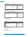
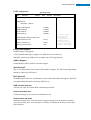
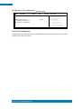
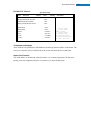
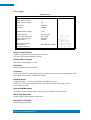
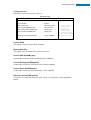
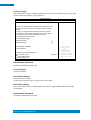
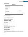
SI-22 Series User Manual 2013 Dec V1 SI-22 User Manual Copyright © 2013 All Rights Reserved. No part of this manual, including the products and software described in it, may be reproduced, transmitted, transcribed, stored in a retrieval system, or translated into any language in any form or by any means, except documentation kept by the purchaser for backup purposes, without the express written permission of the authors. Products and corporate names mentioned in this manual may or may not be registered trademarks or copyrights of their respective companies, and are used for identification purposes only. All trademarks are the property of their respective owners. Every effort has been made to ensure that the contents of this manual are correct and up to date. However, the manufacturer makes no guarantee regarding the accuracy of its contents, and reserves the right to make changes without prior notice. 1 SI-22 User Manual 2 Table of Contents Setting up your system ........................................................................................................ 3 Care during use .................................................................................................................... 4 Acknowledgments ............................................................................................................... 5 CHAPTER 1 INTRODUCTION .................................................................................... 6 1.1 General Description ....................................................................................................... 6 1.2 System Specifications..................................................................................................... 7 1.2.2 Dimensions ................................................................................................................. 8 1.2.3 I/O View ...................................................................................................................... 9 1.3 Exploded View of the SI-22 Assembly ......................................................................... 10 1.3.1 Parts Description ....................................................................................................... 10 1.4 Packing List ................................................................................................................... 10 1.4.1 Optional Items .......................................................................................................... 11 1.5 HARDWARE INSTALLATION .......................................................................................... 12 1.5.1 Installing the Wireless Module ................................................................................. 12 1.5.2 Installing the mSATA Module .................................................................................... 14 CHAPTER 2 MOTHERBOARD INTRODUCTION .........................................................16 2.1 Installing the Memory ................................................................................................. 16 2.2 Setting the Jumpers ..................................................................................................... 17 2.3 Connectors on IB922 .................................................................................................... 18 CHAPTER 3 BIOS SETUP .........................................................................................20 CHAPTER 4 DRIVERS INSTALLATION .......................................................................37 4.1 VGA Drivers Installation ............................................................................................... 37 4.2 Realtek HD Audio Driver Installation ........................................................................... 41 4.3 LAN Drivers Installation ............................................................................................... 42 Appendix ...............................................................................................................43 Mounting SI-22 to the Wall................................................................................................ 43 Wall Mounting Requirements............................................................................................ 44 Selecting the Location........................................................................................................ 44 SI-22 User Manual Safety Information Your SI-22 is designed and tested to meet the latest standards of safety for information technology equipment. However, to ensure your safety, it is important that you read the following safety instructions Setting up your system Read and follow all instructions in the documentation before you operate your system. Do not use this product near water. Set up the system on a stable surface. Do not secure the system on any unstable plane. Do not place this product on an unstable cart, stand, or table. The product may fall, causing serious damage to the product. Slots and openings on the chassis are for ventilation. Do not block or cover these openings. Make sure you leave plenty of space around the system for ventilation. Never insert objects of any kind into the ventilation openings. This system should be operated from the type of power indicated on the marking label. If you are not sure of the type of power available, consult your dealer or local power company. Use this product in environments with ambient temperatures between 0˚C and 45˚C. If you use an extension cord, make sure that the total ampere rating of the devices plugged into the extension cord does not exceed its ampere rating. DO NOT LEAVE THIS EQUIPMENT IN AN ENVIRONMENT WHERE THE STORAGE TEMPERATURE MAY GO BELOW -20° C (-4° F) OR ABOVE 80° C (176° F). THIS COULD DAMAGE THE EQUIPMENT. THE EQUIPMENT SHOULD BE IN A CONTROLLED ENVIRONMENT. 3 SI-22 User Manual Care during use Do not walk on the power cord or allow anything to rest on it. Do not spill water or any other liquids on your system. When the system is turned off, a small amount of electrical current still flows. Always unplug all power, and network cables from the power outlets before cleaning the system. If you encounter the following technical problems with the product, unplug the power cord and contact a qualified service technician or your retailer. The power cord or plug is damaged. Liquid has been spilled into the system. The system does not function properly even if you follow the operating instructions. The system was dropped or the cabinet is damaged. Lithium-Ion Battery Warning CAUTION: Danger of explosion if battery is incorrectly replaced. Replace only with the same or equivalent type recommended by the manufacturer. Dispose of used batteries according to the manufacturer’s instructions. NO DISASSEMBLY The warranty does not apply to the products that have been disassembled by users WARNING HAZARDOUS MOVING PARTS KEEP FINGERS AND OTHER BODY PARTS AWAY 4 5 Acknowledgments AMI is a registered trademark of AMI Software International, Inc. AMD and ATI are registered trademarks of AMD Corporation. Microsoft Windows is a registered trademark of Microsoft Corporation. FINTEK is a registered trademark of FINTEK Electronics Corporation. REALTEK is a registered trademark of REALTEK Electronics Corporation. All other product names or trademarks are properties of their respective owners. Copyright © 2013 All Rights Reserved. SI-22 User Manual 6 CHAPTER 1 INTRODUCTION 1.1 General Description The “Signature Book™” SI -22 is a professional fanless digital signage system powered by the new AMD Embedded new generation G-Series quad-core APU with DASH compliance for remote control, and compact & slim design. It supports 2x HDMI, 1x RJ45 for LAN, 1x RJ45 for RS232, 1x USB2.0 and 2x USB3.0 ports to give a wide selection for data communication in display applications. 7 1.2 System Specifications 1.2.1 Hardware Specifications Model Name SI-22 System Mainboard IB922 CPU AMD Embedded G-Series SoC; 4 Cores @ 1.5GHz APU FT3 BGA package Chipset SoC Integrated Memory 1x DDR3 1600 MHz SO-DIMM, Max. 8GB (Non-ECC) I/O Interface 2x HDMI 1.4a 2x USB 3.0 ports, 1x USB 2.0 port 1x RJ45 for LAN, 1x RJ45 for RS232 2x Microjack audio connectors for Line-in / Line-out Power LED, 1x power on/off button 1x DC jack Storage 1 x mSATA Expansion Slots 1x mPCIe(x1) for WiFi + Bluetooth, 3G, and TV tuner options 1x UIM/SIM card slot (for 3G/LTE adapter in mPCIe slot) Power Supply +12V DC-in with 60W power adaptor Construction Aluminum + SGCC Chassis Color Black & White Mounting STD system bracket Dimensions 190mm(W) x 130mm(D) x 19.5mm(H) 7.5”(W) x 5.1”(D) x 0.77”(H) Operating Temperature 0°C~ 45°C (32°F~113°F) Storage Temperature -20° ~ 80°C (-4°F~176°F) Relative Humidity 5~90% @45°C (non-condensing) Vibration mSATA: 5 Grms/5~500Hz random operation RoHS Available Certification CE, FCC, UL, CCC ‧This specification is subject to change without prior notice. Copyright © 2013 All Rights Reserved. SI-22 User Manual 1.2.2 Dimensions 8 9 1.2.3 I/O View Item Connector Item Connector 1 Line-in 6 2x USB 3.0 2 Line-out 7 1x USB 2.0 3 2x HDMI 1.4a 8 DC jack 4 1x RJ45 for RS232 9 Power LED 5 1x RJ45 for LAN 10 Power on/off button Copyright © 2013 All Rights Reserved. SI-22 User Manual 1.3 Exploded View of the SI-22 Assembly 1.3.1 Parts Description Part No. Description Part No. Description 1 IB922 motherboard 2 SI-22 Base 3 SI-22 Cover 4 SI-22 heatsink 1.4 Packing List Item No. Description Qty 1 Driver CD 1 2 Power adaptor 1 3 Power Cord 1 10 11 1.4.1 Optional Items WiFi Solution Description QCOM WiFi module Wireless LAN Card; 802.11 B/G/N+BT HALF Card [Q802XKN3B] RoHS (A008WIRELESS00700P) External Antenna WiFi Antenna (A055RFA02C2M20800P) Internal cable-1/2 From WiFi module to Rear/Front panel (A055RFA0000021000P/A055RFA0000032000P) Bracket MPCIE-EXT V-B1 Bracket, RoHS; Extend Half to Full size. (SC2MPCIEEXT0B1100P) 3G Solution Description ZU 202 Wireless; 3.75G UMTS/HSPA [ZU202] RoHS (A008WIRELESS00520P) ZU 200 Wireless; 3.75G UMTS/HSPA & GPS Module [ZU200] RoHS (A008WIRELESS00510P) Cable Cable; Antenna-2 30CM P 2pcs (C501ANT0200300000P) Antenna Antenna; 3G, P, 2pcs (A055ANT0921Q2P000P) COM Port Cable Description EXT-222 Cable; EXT-222 2-HD 7C 150CM; JACK-8=>DSU-9F RoHS (C501EXT2227A12000P) EXT-424 Cable; EXT-424 2-HD 8C 90CM; RJ45 JACK-8M=>DSU-9F RoHS (C501EXT4240902000P) EDID Dongle Description H8246JT021-001 EDID Emulator Dongle (HDMI), ADAPTER; HDMI 19P A/M TO A/F (A025HDMI001010000P) Copyright © 2013 All Rights Reserved. SI-22 User Manual 1.5 HARDWARE INSTALLATION 1.5.1 Installing the Wireless Module 1. Remove the six screws on the sides that are used to secure the white cover to the chassis. Once all the screws are removed, from the side, push the cover forward to remove it. 12 13 2. Push the WIFI module into the slot. Screw two screws to secure the module in the slot. Copyright © 2013 All Rights Reserved. SI-22 User Manual 1.5.2 Installing the mSATA Module 1. Remove the six screws on the sides that are used to secure the white cover to the chassis. Once all the screws are removed, from the side, push the cover forward to remove it. 14 15 2. Push the mSATA module into the slot. Screw two screws to secure the module in the slot. Copyright © 2013 All Rights Reserved. SI-22 User Manual 16 CHAPTER 2 MOTHERBOARD INTRODUCTION 2.1 Installing the Memory The IB922 board supports one DDR3 memory socket for a maximum total memory of 8GB. Installing and Removing Memory Modules To install the DDR3 modules, locate the memory slot on the board and perform the following steps: 1. Hold the DDR3 module so that the key of the DDR3 module aligned with that on the memory slot. 2. Gently push the DDR3 module in an upright position until the clips of the slot close to hold the DDR3 module in place when the DDR3 module touches the bottom of the slot. 3. To remove the DDR3 module, press the clips with both hands. 17 2.2 Setting the Jumpers Jumpers are used on IB922 to select various settings and features according to your needs and applications. Contact your supplier if you have doubts about the best configuration for your needs. The following lists the jumper and connectors on IB922 and their respective functions. Jumper Locations on IB922 JBAT1: Clear CMOS Contents JBAT1 Setting Pin 1-2 Short/Closed Pin 2-3 Short/Closed Copyright © 2013 All Rights Reserved. Function Normal Clear CMOS SI-22 User Manual 2.3 Connectors on IB922 SW1: Power On Button CN1: Gigabit LAN (RTL8111DP) CN2: COM1/RS232 Serial Port (RJ45 TYPE) Signal Name Pin # Pin # Signal Name RTS, Request to send 1 2 Data terminal ready TXD, Transmit data 3 4 GND, ground GND, ground 5 6 RXD, Receive data DSR, Data set ready 7 8 CTS, Clear to send CN3, CN4: USB 3.0 Connector CN5: USB 2.0 Connector CN6: Board Input Power Connector CN7, CN8: HDMI Connector 18 19 J1: SPI Flash Connector (factory use only) J2: Mini PCIE Connector (with USB SIM support) J3: Battery Connector J6: DDR3 SO-DIMM Socket J7: Mini PCIE Connector (w/ M-SATA support) J11: Audio LINE_IN Connector J12: Audio LINE_OUT Connector LED6: Power On LED Copyright © 2013 All Rights Reserved. SI-22 User Manual 20 CHAPTER 3 BIOS SETUP This chapter describes the different settings available in the BIOS that comes with the board. The topics covered in this chapter are as follows: 3.1 BIOS Introduction The BIOS (Basic Input/Output System) installed in your computer system’s ROM provides critical low-level support for a standard device such as disk drives, serial ports and parallel ports. It also adds virus and password protection as well as special support for detailed fine-tuning of the chipset controlling the entire system. 3.2 BIOS Setup The BIOS provides a Setup utility program for specifying the system configurations and settings. The BIOS ROM of the system stores the Setup utility. When you turn on the computer, the BIOS is immediately activated. Pressing the <Del> key immediately allows you to enter the Setup utility. If you are a little bit late pressing the <Del> key, POST (Power On Self Test) will continue with its test routines, thus preventing you from invoking the Setup. If you still wish to enter Setup, restart the system by pressing the ”Reset” button or simultaneously pressing the <Ctrl>, <Alt> and <Delete> keys. You can also restart by turning the system Off and back On again. The following message will appear on the screen: Press <DEL> or <ESC> to Enter Setup In general, you press the arrow keys to highlight items, <Enter> to select, the <PgUp> and <PgDn> keys to change entries, <F1> for help and <Esc> to quit. When you enter the Setup utility, the Main Menu screen will appear on the screen. The Main Menu allows you to select from various setup functions and exit choices. 21 Main Settings Aptio Setup Utility – Copyright © 2011 American Megatrends, Inc. Main Advanced Chipset Boot Security Save & Exit Choose the system default language BIOS Information Memory Information Total memory 8176 MB (DDR3) System Date System Time [Tue 01/20/2009] [15:27:20] Access Level Administrator → ← Select Screen ↑↓ Select Item Enter: Select +- Change Field F1: General Help F2: Previous Values F3: Optimized Default F4: Save ESC: Exit System Date Set the Date. Use Tab to switch between Data elements. System Time Set the Time. Use Tab to switch between Data elements. Advanced Settings This section allows you to configure and improve your system and allows you to set up some system features according to your preference. Aptio Setup Utility Main Advanced Chipset ► PCI Subsystem Settings ► ACPI Settings ► CPU Configuration ► IDE Configuration ► Shutdown Temperature Configuration ► iSmart Controller ► USB Configuration ► F81866 Super IO Configuration ► F81866 H/W Monitor Copyright © 2013 All Rights Reserved. Boot Security Save & Exit → ← Select Screen ↑↓ Select Item Enter: Select +- Change Field F1: General Help F2: Previous Values F3: Optimized Default F4: Save ESC: Exit SI-22 User Manual PCI Subsystem Settings Aptio Setup Utility Main Advanced PCI Bus Driver Version PCI Common Settings PCI Latency Timer VGA Palette Snoop PERR# Generation SERR# Generation ► PCI Express Settings Chipset Boot Security V 2.0502 Save & Exit → ← Select Screen ↑↓ Select Item Enter: Select 32 PCI Bus Clocks +- Change Field F1: General Help Disabled F2: Previous Values Disabled F3: Optimized Default Disabled F4: Save ESC: Exit PCI Latency Timer Value to be programmed into PCI Latency Timer Register. VGA Palette Snoop Enables or disables VGA Palette Registers Snooping. PERR# Generation Enables or disables PCI device to generate PERR#. SERR# Generation Enables or disables PCI device to generate SERR#. 22 23 PCI Express Settings Aptio Setup Utility Main Advanced Chipset Boot PCI Express Device Register Settings Relaxed Ordering Extended Tag No Snoop Maximum Payload Maximum Read Request PCI Express Link Register Settings ASPM Support WARNING: Enabling ASPM may cause PCI-E devices to fail Extended Synch Link Training Retry Link Training Timeout (uS) Unpopulated Links Security Save & Exit Disabled Disabled Enabled Auto Auto Disabled Disabled Disabled 5 100 Keep Link ON → ← Select Screen ↑↓ Select Item Enter: Select +- Change Field F1: General Help F2: Previous Values F3: Optimized Default F4: Save ESC: Exit ACPI Settings Aptio Setup Utility Main Advanced Chipset Boot Security Save & Exit ACPI Settings → ←Select Screen Enable ACPI Auto Configuration Disabled Enable Hibernation Enabled ACPI Sleep State S3 (Suspend to R…) Lock Legacy Resources Disabled ↑↓Select Item Enter: Select +- Change Field F1: General Help F2: Previous Values F3: Optimized Default F4: Save ESC: Exit Enable Hibernation Enables or Disables System ability to Hibernate (OS/S4 Sleep State). This option may be not effective with some OS. ACPI Sleep State Select ACPI sleep state the system will enter, when the SUSPEND button is pressed. Lock Legacy Resources Enabled or Disabled Lock of Legacy Resources. Copyright © 2013 All Rights Reserved. SI-22 User Manual CPU Configuration This section shows the CPU configuration parameters. Aptio Setup Utility Main Advanced CPU Configuration Chipset Boot Security Save & Exit Module Version: 4.6.5.1 TrinityPI 012 AGESA Version: 1.0.0.3 PSS Support PSTATE Adjustment NX Mode SVM Mode CPB Mode C6 Mode ► Node 0 Information Enable Pstate 0 Enable Enable Auto Enable → ← Select Screen ↑↓ Select Item Enter: Select +- Change Field F1: General Help F2: Previous Values F3: Optimized Default F4: Save ESC: Exit PSS Support Enable/disable the generation of ACPI _PPC, _PPC, _PSS, and _PCT objects. PSTATE Adjustment Provide to adjust startup P-state level. PPC Adjustment Provide to adjust _PPC object. NX Mode Enable/disable No-execute page protection function. SVM Mode Enable/disable CPU Virtualization. CPB Mode Enable/disable CPB. C6 Mode Auto/disable CPB. Node 0 Information View memory information related to Node 0. 24 25 IDE Configuration Aptio Setup Utility Main Advanced Chipset Boot Security IDE Configuration SATA Port0 InnoLite CFast (16.0GB) SATA Port2 Not Present Save & Exit → ← Select Screen ↑↓ Select Item Enter: Select +- Change Field F1: General Help F2: Previous Values F3: Optimized Default F4: Save ESC: Exit Shutdown Temperature Configuration Aptio Setup Utility Main Advanced Chipset Boot APCI Shutdown Temperature Security Save & Exit → ← Select Screen ↑↓ Select Item Enter: Select +- Change Field F1: General Help F2: Previous Values F3: Optimized Default F4: Save ESC: Exit Disabled ACPI Shutdown Temperature The default setting is Disabled. iSmart Controller Aptio Setup Utility Main Advanced Chipset Boot iSmart Controller Power-On after Power failure Disable Schedule Slot 1 None Schedule Slot 2 None Power-On after Power failure Enable or Disable. Schedule Slot 1 / 2 Setup the hour/minute for system power on. Copyright © 2013 All Rights Reserved. Security Save & Exit → ← Select Screen ↑↓ Select Item Enter: Select +- Change Field F1: General Help F2: Previous Values F3: Optimized Default F4: Save ESC: Exit SI-22 User Manual USB Configuration Aptio Setup Utility Main Advanced Chipset Boot Security Save & Exit USB Configuration USB Devices: 1 Keyboard, 1 Mouse Legacy USB Support Enabled USB3.0 Support Enabled XHCI Hand-off Enabled EHCI Hand-off Enabled USB hardware delays and time-outs: USB Transfer time-out 20 sec Device reset tine-out 20 sec Device power-up delay Auto → ← Select Screen ↑↓ Select Item Enter: Select +- Change Field F1: General Help F2: Previous Values F3: Optimized Default F4: Save ESC: Exit Legacy USB Support Enables Legacy USB support. AUTO option disables legacy support if no USB devices are connected. DISABLE option keeps USB devices available only for EFI applications. USB3.0 Support Enable/Disable USB3.0 (XHCI) Controller support. XHCI Hand-off This is a workaround for OSes without XHCI hand-off support. The XHCI ownership change should be claimed by XHCI driver. EHCI Hand-off Enabled/Disabled. This is a workaround for OSes without EHCI hand-off support. The EHCI ownership change should be claimed by EHCI driver. USB Transfer time-out The time-out value for Control, Bulk, and Interrupt transfers. Device reset time-out USB mass Storage device start Unit command time-out. Device power-up delay Maximum time the device will take before it properly reports itself to the Host Controller. ‘Auto’ uses default value: for a Root port it is 100ms, for a Hub port the delay is taken from Hub descriptor. 26 27 F81866 Super IO Configuration Aptio Setup Utility Main Advanced Chipset Boot Security Save & Exit F81866 Super IO Configuration F81866 Super IO Chip ► Serial Port 0 Configuration ► Serial Port 1 Configuration F81866 → ← Select Screen ↑↓ Select Item Enter: Select +- Change Field F1: General Help F2: Previous Values F3: Optimized Default F4: Save ESC: Exit Serial Port Configuration Set Parameters of serial ports. User can Enable/Disable the serial port and select an optimal settings for the Super IO device. Copyright © 2013 All Rights Reserved. SI-22 User Manual F81866 H/W Monitor Aptio Setup Utility Main Advanced Chipset Boot Security Save & Exit PC Health Status System Smart Fan Function 50 C CPU Smart Fan Function SYS_Fan2 smart fan control 50 C 50 C SYS Temp +35 C CPU Temp +52 C Vcore +1.000 V +5V +4.413 V +12V +11.408 V +1.5V +1.544 V → ← Select Screen ↑↓ Select Item Enter: Select +- Change Field F1: General Help F2: Previous Values F3: Optimized Default F4: Save ESC: Exit Temperatures/Voltages These fields are the parameters of the hardware monitoring function feature of the board. The values are read-only values as monitored by the system and show the PC health status. Smart Fan Function This field enables or disables the smart fan feature. At a certain temperature, the fan starts turning. Once the temperature drops to a certain level, it stops turning again. 28 29 Chipset Settings This section allows you to configure and improve your system and allows you to set up some system features according to your preference. Aptio Setup Utility Main Advanced Chipset Boot Security Save & Exit → ← Select Screen ↑↓ Select Item Enter: Select +- Change Field F1: General Help F2: Previous Values F3: Optimized Default F4: Save ESC: Exit ► South Bridge ► North Bridge Aptio Setup Utility Main Advanced Chipset AMD Reference code Version: ► SB SATA Configuration ► SB USB Configuration Copyright © 2013 All Rights Reserved. Boot Security Trinity PI 1.0.0.3 Save & Exit → ← Select Screen ↑↓ Select Item Enter: Select +- Change Field F1: General Help F2: Previous Values F3: Optimized Default F4: Save ESC: Exit SI-22 User Manual Aptio Setup Utility Main Advanced Chipset Boot Security OnChip SATA Channel Enabled OnChip SATA Type Native iDE OnChip iDE mode Legacy mode SATA IDE Combined Mode Enabled Save & Exit → ←Select Screen ↑↓ Select Item Enter: Select +- Change Field F1: General Help F2: Previous Values F3: Optimized Default F4: Save ESC: Exit OnChip SATA Channel Enabled or Disabled. OnChip SATA Type Native IDE /n RAID /n AHCI /n AHCI /n Legacy IDE /n IDE->AHCI /n HyperFlash OnChip IDE mode Legacy mode or Native mode SATA IDE Combined Mode Enabled or Disabled. 30 31 SB USB Configuration Options: Main Advanced Chipset Boot Security XHCI Controller 0 Enabled XHCI Controller 1 Enabled DHCI HC(Bus 0 Dev 18 Fn 0) Enabled EHCI HC(Bus 0 Dev 18 Fn 2) Enabled DHCI HC(Bus 0 Dev 19 Fn 0) Enabled EDHCI HC(Bus 0 Dev 19 Fn 0) Enabled DHCI HC(Bus 0 Dev 20 Fn 5) USB Port 0 USB Port USB Port USB Port USB Port Save & Exit Enabled Enabled Enabled Enabled Enabled Enabled Enabled USB Port USB Port USB Port USB Port USB Port Enabled Enabled Enabled Enabled Enabled XHCI0 Port 0 XHCI0 Port 1 XHCI1 Port 0 Enabled Enabled Enabled XHCI1 Port 1 Enabled Copyright © 2013 All Rights Reserved. → ← Select Screen Select Item ↑↓ Enter: Select +- Change Field F1: General Help F2: Previous Values F3: Optimized Default F4: Save ESC: Exit SI-22 User Manual Aptio Setup Utility Main Advanced Chipset Boot Security Save & Exit North Bridge Configuration → ← Select Screen ↑↓ Select Item Enter: Select +- Change Field F1: General Help F2: Previous Values F3: Optimized Default F4: Save ESC: Exit ► GFX Configuration Memory Information Total memory: 8176 MB (DDR3) ► Socket 0 Information Aptio Setup Utility Main Advanced Chipset Boot Security Save & Exit GFX Configuration Integrated Graphics Auto Integrated Graphics Options are Auto Disabled and Force Aptio Setup Utility Main Advanced Chipset Boot Security Save & Exit Socket 0 Information Starting Address: 0KB Ending Address: 8388607 KB Dimm0: Not Present Dimm1: size=8192 MB, speed=667 MHz → ← Select Screen ↑↓ Select Item Enter: Select +- Change Field F1: General Help F2: Previous Values F3: Optimized Default F4: Save ESC: Exit 32 33 Boot Settings Aptio Setup Utility Main Advanced Chipset Boot Security Boot Configuration Setup Prompt Timeout Bootup NumLock State 1 On Quiet Boot Fast Boot Disabled Disabled CSM16 Module Version 07.69 GateA20 Active Option ROM Messages INT19 Trap Response CSM Support Upon Request Force BIOS Immediate Enabled Boot Option Priorities Boot Option #1 ► CSM parameters SATA PM: WDC WD80 Save & Exit → ← Select Screen ↑↓ Select Item Enter: Select +- Change Field F1: General Help F2: Previous Values F3: Optimized Default F4: Save ESC: Exit Setup Prompt Timeout Number of seconds to wait for setup activation key. 65535(0xFFFF) means indefinite waiting. Bootup NumLock State Select the keyboard NumLock state. Quiet Boot Enables/Disables Quiet Boot option. Fast Boot Enables/Disables boot with initialization of a minimal set of devices required to launch active boot option. Has no effect for BBS boot options. GateA20 Active UPON REQUEST – GA20 can be disabled using BIOS services. ALWAYS – do not allow disabling GA20; this option is useful when any RT code is executed above 1MB. Option ROM Messages Set display mode for Option ROM. Options are Force BIOS and Keep Current. INT19 Trap Response Enable: Allows Option ROMs to trap Int 19. Boot Option Priorities Sets the system boot order. Copyright © 2013 All Rights Reserved. SI-22 User Manual CSM parameters OpROM execution, boot options, filter, etc. Aptio Setup Utility Main Advanced Chipset Boot Security Save & Exit Launch CSM Always Boot option filter UEFI and Legacy → ← Select Screen Launch PXE OpROM policy Do not launch Launch Storage OpROM policy Legacy only Launch Video OpROM policy Legacy only Other PCI device ROM priority Legacy OpROM ↑↓ Select Item Enter: Select +- Change Field F1: General Help F2: Previous Values F3: Optimized Default F4: Save ESC: Exit Launch CSM This option controls if CSM will be launched. Boot option filter This option controls what devices system can boot to. Launch PXE OpROM policy Controls the execution of UEFI and Legacy PXE OpROM. Launch Storatge OpROM policy Controls the execution of UEFI and Legacy Storage OpROM. Launch Video OpROM policy Controls the execution of UEFI and Legacy Video OpROM. Other PCI device ROM priority For PCI devices other than Network, Mass storage or Video defines which OpROM to launch. 34 35 Security Settings This section allows you to configure and improve your system and allows you to set up some system features according to your preference. Aptio Setup Utility Main Advanced Chipset Boot Security Save & Exit Password Description If ONLY the Administrator’s password is set, then this only limit access to Setup and is only asked for when entering Setup. If ONLY the User’s password is set, then this is a power on password and must be entered to boot or enter Setup. In Setup the User will have Administrator rights The password length must be in the following range: Minimum length 3 Maximum length 20 Administrator Password User Password UEFI Secure Boot Management Secure Boot control ► Secure Boot Policy ►Key Management Enabled → ← Select Screen ↑↓ Select Item Enter: Select +- Change Field F1: General Help F2: Previous Values F3: Optimized Default F4: Save ESC: Exit Administrator Password Set Setup Administrator Password. User Password Set User Password. Secure Boot control Secure Boot flow control. Secure Boot is possible only if System runs in User Mode. Secure Boot Policy Select Secure Boot mode extended options: Internal FV, Option ROM, Removable Media, Fixed Media. Administrator Password Set Setup Administrator Password. Copyright © 2013 All Rights Reserved. SI-22 User Manual Save & Exit Settings Aptio Setup Utility Main Advanced Chipset Boot Security Save & Exit Save Changes and Exit Discard Changes and Exit Save Changes and Reset Discard Changes and Reset Save Options Save Changes Discard Changes Restore Defaults Save as User Defaults Restore User Defaults Boot Override → ← Select Screen ↑↓ Select Item Enter: Select +- Change Field F1: General Help F2: Previous Values F3: Optimized Default F4: Save ESC: Exit Launch EFI Shell from filesystem device Save Changes and Exit Exit system setup after saving the changes. Discard Changes and Exit Exit system setup without saving any changes. Save Changes and Reset Reset the system after saving the changes. Discard Changes and Reset Reset system setup without saving any changes. Save Changes Save Changes done so far to any of the setup options. Discard Changes Discard Changes done so far to any of the setup options. Restore Defaults Restore/Load Defaults values for all the setup options. Save as User Defaults Save the changes done so far as User Defaults. Restore User Defaults Restore the User Defaults to all the setup options. Launch EFI Shell from filesystem device Attempts to launch EFI Shell application (Shellx64.efi) from one of the available filesystem devices. 36 37 CHAPTER 4 DRIVERS INSTALLATION This section describes the installation procedures for software and drivers. The software and drivers are included with your package. If you find the items missing, please contact the vendor where you made the purchase. IMPORTANT NOTE: After installing your Windows operating system, you must install first the Intel Chipset Software Installation Utility before proceeding with the drivers installation. 4.1 VGA Drivers Installation 1. Insert the drivers DVD that comes with the board. Click AMD, then AMD eKabini Chipset Drivers. 2. Click AMD eKabini Graphics Drivers. Copyright © 2013 All Rights Reserved. SI-22 User Manual 3. When the welcome screen appears, click Next. 4. Select the language you would like to be displayed and click Next. 5. Click Install to continue the installation process. 38 39 6. Select Express and the installation location and click Next. Copyright © 2013 All Rights Reserved. SI-22 User Manual 7. Click Accept to accept the End User License Agreement. 8. To reboot the system, click Yes. 40 41 4.2 Realtek HD Audio Driver Installation 1. Click Realtek High Definition Audio Driver. 2. On the Welcome to the InstallShield Wizard screen, click Next to proceed with and complete the installation process. 3. Restart the computer when prompted. Copyright © 2013 All Rights Reserved. SI-22 User Manual 42 4.3 LAN Drivers Installation 1. Insert the CD that comes with the board. 2. Click LAN Card and then Realtek RTL8111G LAN Controller Drivers. 3. In the Welcome screen, click Next. 4. In the License Agreement screen, click I accept the terms in license agreement and Next to accept the software license agreement and proceed with the installation process. 5. Click the checkbox for Drivers in the Setup Options screen to select it and click Next to continue. 6. When the Ready to Install the Program screen appears, click Install to continue. 7. When InstallShield Wizard is complete, click Finish. 43 Appendix Mounting SI-22 to the Wall You can install SI-22 on plastic (LCD monitor), wood, drywall surface over studs, or a solid concrete or metal plane directly. Ensure the installer uses at least two M3 length 6mm screws to secure the system on the wall. Four M3 length 6mm screws are recommended to secure the system onto the wall. Fasteners are not included with the unit, and must be supplied by the installer. The types of fasteners required are dependent on the type of wall construction. Choose fasteners that are rated either ”Medium Duty“ or ”Heavy Duty.“ To assure proper fastener selection and installation, follow the fastener manufacturer’s recommendations. Copyright © 2013 All Rights Reserved. SI-22 User Manual 44 Wall Mounting Requirements Note: Before mounting the system onto the wall, ensure that you are following all applicable building and electric codes. When mounting, ensure that you have enough room for power and signal cable routing and have good ventilation for power adapter. The method of mounting must be able to support the weight of SI-22 plus the suspend weight of all the cables to be attached to the system. Use the following methods for mounting your system: Mounting to hollow walls Method 1: Wood surface – A minimum wood thickness– 38mm (1.5in.) by 25.4 cm (10in.) – of high, construction – grade wood is recommended. Note: This method provides the most reliable attachment of the unit with little risk that the unit will come loose or require ongoing maintenance. Method 2: Drywall walls - Drywall over wood studs is acceptable. Mounting to a solid concrete or brick wall - Mounts on a flat smooth surface. Selecting the Location Plan the mounting location thoroughly. Locations such as walkway areas, hallways, and crowded areas are not recommended. Mount the unit to a flat, sturdy, structurally sound column or wall surface. The best mounting surface is a standard countertop, cabinet, table, or other structure that is minimally the width and length of the unit. This recommendation reduces the risk that someone may accidentally walk into and damage the device. Local laws governing the safety of individuals might require this type of consideration.