1
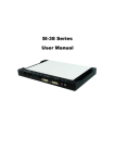
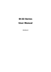
SI-38
User Manual
2012 Jul V1
Copyright © 2012, All Rights Reserved.
No part of this manual, including the products and software described in it, may be
reproduced, transmitted, transcribed, stored in a retrieval system, or translated into
any language in any form or by any means, except documentation kept by the purchaser for backup purposes, without the express written permission of the author.
Products and corporate names mentioned in this manual may or may not be registered trademarks or copyrights of their respective companies, and are used for
identification purposes only. All trademarks are the property of their respective
owners.
Every effort has been made to ensure that the contents of this manual are correct
and up to date. However, the manufacturer makes no guarantee regarding the
accuracy of its contents, and reserves the right to make changes without prior notice.
Some information may change without notice, Engineering specs may differ slightly.
All pictures are for reference only.
2
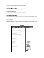
Table of Contents
Safety Information .................................................................................................. 4 Setting up your system ................................................................................................... 4 Care during use .............................................................................................................. 4 Acknowledgments .......................................................................................................... 5 Accessories .............................................................................................................. 7 Components ............................................................................................................ 7 I/O View ........................................................................................................................ 7 Specification ........................................................................................................... 9 Mounting SI‐38 to the Wall ..................................................................................... 9 Wall mounting requirements ........................................................................................ 10 Selecting the location ................................................................................................... 11 Exploded view of the SI‐38 assembly ..................................................................... 11 Parts description .......................................................................................................... 12 Installation ........................................................................................................... 12 Installing CPU ............................................................................................................... 12 Installing the memory .................................................................................................. 13 Setting Jumper ...................................................................................................... 14 Jumper Locations on IB938 ........................................................................................... 15 Connectors on IB938 ............................................................................................. 17 Drivers Installation ................................................................................................ 42 Appendix .............................................................................................................. 48 3
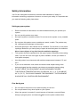
Safety Information
Your SI-38 is designed and tested to meet the latest standards of safety for
information technology equipment. However, to ensure your safety, it is important that
you read the following safety instructions.
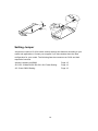
Setting up your system
Read and follow all instructions in the documentation before you operate your
system.
Do not use this product near water.
Set up the system on a stable surface. Do not secure the system on any unstable
plane.
Do not place this product on an unstable cart, stand, or table. The product may
fall, causing serious damage to the product.
Slots and openings on the chassis are for ventilation. Do not block or cover these
openings. Make sure you leave plenty of space around the system for ventilation.
Never insert objects of any kind into the ventilation openings.
This system should be operated from the type of power indicated on the marking
label. If you are not sure of the type of power available, consult your dealer or
local power company.
Use this product in environments with ambient temperatures between 0˚C and
45˚C.
If you use an extension cord, make sure that the total ampere rating of the
devices plugged into the extension cord does not exceed its ampere rating.
DO NOT LEAVE THIS EQUIPMENT IN AN ENVIRONMENT WHERE
THESTORAGE TEMPERATURE MAY GO BELOW -20° C (-4° F) OR ABOVE
80° C (176° F). THIS COULD DAMAGE THE EQUIPMENT. THE EQUIPMENT
SHOULD BE IN A CONTROLLED ENVIRONMENT.
Care during use
Do not walk on the power cord or allow anything to rest on it.
Do not spill water or any other liquids on your system.
When the system is turned off, a small amount of electrical current still flows.
Always unplug all power, and network cables from the power outlets before
4
cleaning the system.
If you encounter the following technical problems with the product, unplug the
power cord and contact a qualified service technician or your retailer.
The power cord or plug is damaged.
Liquid has been spilled into the system.
The system does not function properly even if you follow the operating
instructions.
The system was dropped or the cabinet is damaged.
Lithium-Ion Battery Warning
CAUTION: Danger of explosion if battery is incorrectly replaced. Replace only with
the same or equivalent type recommended by the manufacturer. Dispose of used
batteries according to the manufacturer’s instructions.
NO DISASSEMBLY
The warranty does not apply to the products that have been disassembled by users
WARNING
HAZARDOUS MOVING PARTS
KEEP FINGERS AND OTHER BODY PARTS AWAY
5
Acknowledgments
AMI is a registered trademark of AMI Software International, Inc.
AMD and ATI are registered trademarks of AMD Corporation.
Microsoft Windows is a registered trademark of Microsoft Corporation.
FINTEK is a registered trademark of FINTEK Electronics Corporation.
REALTEK is a registered trademark of REALTEK Electronics Corporation.
All other product names or trademarks are properties of their respective owners.
6
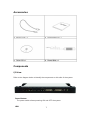
Accessories
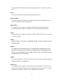
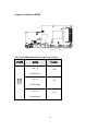
Components
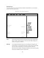
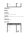
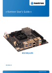
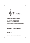
I/O View Refer to the diagram below to identify the components on this side of the system.
Power Bottom
The power switch allows powering ON and OFF the system.
HDD
7
The hard disk LED blinks when data is being written into or read from the hard
disk
Power
The power LED illuminated when system been power on.
Dual Link DVI-I
The Dual Link DVI-I interface to transmitting uncompressed digital data come
from A70 (Accelerated Processing Unit).
Hybrid DVI-I
The Hybrid DVI-I interface can support HDMI (with audio)to transmitting
uncompressed digital data come from A70 (Accelerated Processing Unit).
LAN 1
The eight-pin RJ-45 LAN port supports a standard Ethernet cable for connection
to a local network.
COM 1
Communication or serial port is compatible with RJ 45 interface without RI (ring
indicator) signal.
USB1/2
The USB (Universal Serial Bus) port is compatible with USB devices such as
keyboards, mouse devices, cameras, and hard disk drives. USB allows many
devices to run simultaneously on a single computer, with some peripheral acting
as additional plug-in sites or hubs.
AUDIO
The stereo audio jack (3.5mm) is used to connect the system’s audio out signal to
amplified speakers or headphones.
DC-IN 12 V
The supplied power adapter converts AC power to DC power for use with this
jack. Power supplied through this jack supplies power to the system. To prevent
damage to the system, always use the supplied power adapter.
8
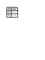
Specification
System Mainboard IB938 Chassis Color Black / White Storage 2.5” 250GB SATA HDD x 1 Mounting Wall mount Power Supply 80W DC adapter Operating Temperature 0°C ~ 45°C (32°F ~ 113°F) Storage Temperature ‐20°C ~ 80°C Relative Humidity 5~90% @45°C (non‐condensing) Vibration HDD: 0.25 Grms/5~500Hz random operation Shock HDD: 15 Grms peak acceleration (11 msec duration) RoHS Available ‧This specification is subject to change without prior notice. Mounting SI-38 to the Wall
9
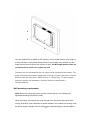
You can install SI-38 on plastic (LCD monitor), wood, drywall surface over studs, or
a solid concrete or metal plane directly. Ensure the installer uses at least four M3
length 6mm screws to secure the system on wall. Six M3 length 6mm screws are
recommended to secure the system on wall.
Fasteners are not included with the unit, and must be supplied by the installer. The
types of fasteners required are dependent on the type of wall construction. Choose
fasteners that are rated either ”Medium Duty“ or ”Heavy Duty.“ To assure proper
fastener selection and installation, follow the fastener manufacturer’s
recommendations.
Wall mounting requirements Note: Before mounting the system on wall, ensure that you are following all
applicable building and electric codes.
When mounting, ensure that you have enough room for power and signal cable
routing. And have good ventilation for power adapter. The method of mounting must
be able to support weight of the SI-38 plus the suspend weight of all the cables to
10
be attached to the system. Use the following methods for mounting your system:
Mounting to hollow walls
Method 1: Wood surface – A minimum wood thickness – 38mm (1.5in.) by
25.4 cm (10in.) – of high, construction – grade wood is recommended.
Note: This method provides the most reliable attachment of the unit with
little risk that the unit will come loose or require ongoing maintenance.
Method 2: Drywall walls - Drywall over wood studs is acceptable.
Mounting to a solid concrete or brick wall - Mounts on a flat smooth surface.
Selecting the location Plan the mounting location thoroughly. Locations such as walkway areas, hallways,
and crowded areas are not recommended. Mount the unit to a flat, sturdy,
structurally sound column or wall surface.
The best mounting surface is a standard countertop, cabinet, table, or other
structure that is minimally the width and length of the unit. This recommendation
reduces the risk that someone may accidentally walk into and damage the device.
Local laws governing the safety of individuals might require this type of
consideration.
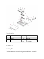
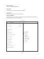
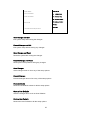
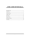
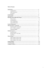
Exploded view of the SI-38 assembly
11
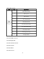
Parts description Part NO. Description
Part NO.
Description
1
Heat Pipe
2
Main die casting chassis
3
Fan set
4
IB938 MB
5
Top Cover
6
Bottom Cover
7
2.5” HDD
Installation
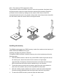
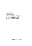
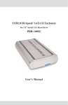
Installing CPU The SI-38 (IB938 board) supports PGA-722 socket for AMD R-Series 32nm QC/DC
12
APU. (The maximum TDP supported is 35W)
The processor socket comes with a screw to secure the processor. As shown in the
left picture below, loosen the screw first before inserting the processor. Place the
processor into the socket by making sure the notch on the corner of the CPU
corresponds with the notch on the inside of the socket. Once the processor has slide
into the socket, fasten the screw. Refer to the figures below.
Installing the memory The IB938 board supports two DDR3 memory socket for a maximum total memory of
8GB in DDR3 SO-DIMM memory type.
Installing and Removing Memory Modules
To install the DDR3 modules, locate the memory slot on the board and perform the
following steps:
1.
Hold the DDR3 module so that the key of the DDR3 module aligns with that on
the memory slot. Insert the module into the socket at a slight angle
(approximately 30 degrees). Note that the socket and module are both keyed,
which means that the module can be installed only in one direction.
2.
To seat the memory module into the socket, apply firm and even pressure to
each end of the module until you feel it slip down into the socket.
3.
With the module properly seated in the socket, rotate the module downward.
Continue pressing downward until the clips at each end lock into position.
4.
To remove the DDR3 module, press the clips with both hands.
13
Setting Jumper
Jumpers are used on SI-38 to select various settings and features according to your
needs and applications. Contact your supplier if you have doubts about the best
configuration for your needs. The following lists the connectors on SI-38 and their
respective functions.
Jumper Locations on IB938
Page 15
JP4, JP5: COM4 RS232 RI/+5V/+12V Power Setting
Page 15
J15: Clear CMOS Setting
Page 16
14
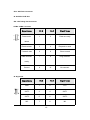
Jumper Locations on IB938 JP4, JP5: COM4 RS232 RI/+5V/+12V Power Setting
JP4/JP5
Setting
Function
Pin 1-2
+12V
Short/Closed
Pin 3-4
RI
Short/Closed
Pin 5-6
+5V
Short/Closed
15
J15: Clear CMOS Setting
JP15
Function
Normal
Clear CMOS
16
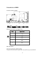
Connectors on IB938
Connector Locations on IB938
CN19: DC_IN Connector (+12V Adaptor 4 Pin)
Pin #
1
2
3
4
5
Signal Name
+12V
+12V
GND
GND
GND
SW1: Power Button
LED3: Power LED (Green), HDD LED (RED)
The green LED at the bottom is power LED. The red LED on top is the HDD LED.
17
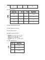
COM1: COM1 Connector
COM1
Pin #
1
Signal Name
DSR, Data set ready
2
GND, ground
3
4
5
6
7
8
9
GND, ground
TXD, Transmit data
RXD, Receive data
DCD, Data carrier detect
DTR, Data terminal ready
CTS, Clear to send
RTS, Request to send
10
RI, Ring indicator
CN15, CN16: USB3.0 Connector
CN14: RJ45 Gigabit LAN
CN13: Dual Link DVI-I Connector
CN3: DVI-I Connector
CN18: Audio MIC-in
CN17: Audio Line out
18
JP13: SPI Flash Connector
J8: Half Mini PCIE Slot
JP9: LPC Debug Port Connector
COM2: COM2 Connector
Signal Name
Signal Name
Pin #
Pin #
Data carrier
1
2
Data set ready
Receive data
3
4
Request to send
Transmit data
5
6
Clear to send
Data terminal
7
8
Ring indicator
9
10
No connect.
detect
ready
Ground
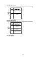
J9: Digital I/O
Signal Name
Pin #
Pin #
Signal Name
GND
1
2
VCC
OUT3
3
4
OUT1
OUT2
5
6
OUT0
IN3
7
8
IN1
19
IN2
9
10
IN0
JP10: US2.0 Connector
Signal Name
Signal Name
Pin #
Pin #
Vcc
1
2
Ground
D-
3
4
D+
D+
5
6
D-
Ground
7
8
Vcc
J12: Mini PCIE Slot (Support mSATA)
J17: MCU JTAG (factory use only)
J19: Power LED Connector
J20: System Function Connector
J19: Power LED Connector
Pin #
Signal Name
1
+5V
2
NC
3
Ground
20
J24: CPU_FAN Connector
This is a 3-pin header for the CPU fan. The fan must be a 12V (500mA).
Pin #
Signal Name
1
Ground
2
+12V
3
Rotation detection
J25: SYS_FAN Connector
This is a 3-pin header for system fans. The fan must be a 12V (500mA).
Pin #
Signal Name
1
Ground
2
+12V
3
Rotation detection
J23: Audio Amplifier
21
BIOS Setup
BIOS Introduction
The BIOS (Basic Input/Output System) installed in your computer system’s ROM provides
critical low-level support for a standard device such as disk drives, serial ports and parallel
ports. It also adds virus and password protection as well as special support for detailed
fine-tuning of the chipset controlling the entire system.
BIOS Setup
The BIOS provides a Setup utility program for specifying the system configurations and
settings. The BIOS ROM of the system stores the Setup utility. When you turn on the
computer, the BIOS is immediately activated. Pressing the <Del> key immediately allows you
to enter the Setup utility. If you are a little bit late pressing the <Del> key, POST (Power On
Self Test) will continue with its test routines, thus preventing you from invoking the Setup. If
you still wish to enter Setup, restart the system by pressing the ”Reset” button or
simultaneously pressing the <Ctrl>, <Alt> and <Delete> keys. You can also restart by turning
the system Off and back On again. The following message will appear on the screen:
Press
<DEL> or <F2> to
Enter
Setup
In general, you press the arrow keys to highlight items, <Enter> to select, the <PgUp>
and <PgDn> keys to change entries, <F1> for help and <Esc> to quit.
When you enter the Setup utility, the Main Menu screen will appear on the screen.
The Main Menu allows you to select from various setup functions and exit choices.
22
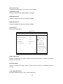
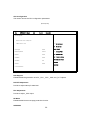
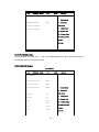
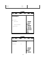
Main BIOS Setup
This setup allows you to record some basic hardware configurations in your computer
system and set the system clock.
Aptio Setup Utility – Copright © 2010 American Megatrends, Inc.
Main
Advanced
Chipset
Boot
Security
Save & Exit
BIOS Information
Choose the system default language
→ ← Select Screen
↑↓
Select Item
Enter: Select
Memory Information
Total memory
8176 MB (DDR3)
+-
Change Field
F1:
General Help
F2:
Previous Values
F3: Optimized Default
F4: Save
System Date
[Tue 01/20/2009]
System Time
[15:27:20]
Access Level
Administrator
Note:
ESC: Exit
If the system cannot boot after making and saving system changes with
Setup, the AMI
BIOS supports an override to the CMOS settings that
resets your system to its default.
Warning:
It is strongly recommended that you avoid making any changes to the
chipset defaults. These defaults have been carefully chosen by both AMI
and your system manufacturer to provide the absolute maximum
performance and reliability. Changing the defaults could cause the system
to become unstable and crash in some cases.
23
System Language
Choose the system default language.
System Date
Set the Date. Use Tab to switch between Data elements.
System Time
Set the Time. Use Tab to switch between Data elements.
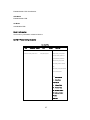
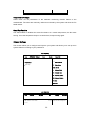
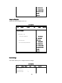
Advanced Settings
This section allows you to configure and improve your system and allows you to set up some
system features according to your preference.
Aptio Setup Utility
Main
Advanced
Chipset
Boot
Security
Save & Exit
Legacy OpROM Support
Launch PXE OpROM
[Disabled]
Launch Storage OpROM
[Enabled]
► PCI Subsystem Settings
► ACPI Settings
► Wake up event setting
→ ← Select
Screen
↑↓ Select Item
► CPU Configuration
Enter: Select
► Shutdown Temperature Configuration
+-
Change Field
► Auto Power On Schedule
F1: General Help
► SATA Configuration
F2: Previous Values
► PCH-FW Configuration
► AMT Configuration
► USB Configuration
F3: Optimized Default
F4: Save & EXIT
ESC: Exit
► Super IO Configuration
► H/W Monitor
► Serial Port Console Redirection
►Sandybridge PPM Configuration
24
PCI Latency Timer
Value to be programmed into PCI Latency Timer Register.
VGA Palette Snoop
Enables or disables VGA Palette Registers Snooping.
PERR# Generation
Enables or disables PCI device to generate PERR#.
SERR# Generation
Enables or disables PCI device to generate SERR#.
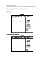
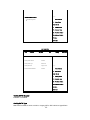
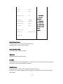
ACPI Settings
System ACPI Parameters.
Aptio Setup Utility
Main
Advanced
Chipset
Boot
Security
Save & Exit
Enable ACPI Auto Configuration
Disabled
→ ← Select
Enable Hibernation
Enabled
↑↓ Select Item
ACPI Sleep State
S3 (Suspend to R…)
Lock Legacy Resources
Disabled
Screen
Enter: Select
+-
Change Field
F1: General Help
F2: Previous Values
F3: Optimized Default
F4: Save & Exit
ESC: Exit
Enable Hibernation
Enables or Disables System ability to Hibernate (OS/S4 Sleep State). This option may be not
effective with some OS.
ACPI Sleep State
Select the highest ACPI sleep state the system will enter, when the SUSPEND button is
pressed.
Lock Legacy Resources
Enables or Disables System Lock of Legacy Resources.
25
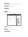
CPU Configuration
This section shows the CPU configuration parameters.
Aptio Setup Utility
Main
Advanced
Chipset
Boot
Security
Save & Exit
CPU Configuration
Module Version: 4.6.5.1 TrinityPI 012
→ ← Select Screen
AGESA Version: 1.0.0.3
↑↓
Select Item
Enter: Select
PSS Support
Enable
PSTATE Adjustment
Pstate 0
NX Mode
Enable
SVM Mode
Enable
CPB Mode
Auto
C6 Mode
Enable
+-
Change Field
F1:
General Help
F2:
Previous Values
F3: Optimized Default
F4: Save
ESC: Exit
► Node 0 Information
PSS Support
Enable/disable the generation of ACPI _PPC, _PPC, _PSS, and _PCT objects.
PSTATE Adjustment
Provide to adjust startup P-state level.
PPC Adjustment
Provide to adjust _PPC object.
NX Mode
Enable/disable No-execute page protection function.
SVM Mode
26
Enable/disable CPU Virtualization.
CPB Mode
Enable/disable CPB.
C6 Mode
Auto/disable CPB.
Node 0 Information
View memory information related to Node 0.
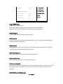
EuP/ErP Power Saving Controller
Aptio Setup Utility
Main
Advanced
Chipset
Boot
Security
Save & Exit
EuP/ErP control on S5
EuP/ErP standby power control
Keep standby power
[Keep standby power] Enable
All of the standby power and
ignore EuP/ErP specification.
[Ethernet Only] Only provide
the standby power for Ethernet
chip.
[No standby power] Shutdown all
of the standby power.
→ ← Select Screen
↑↓
Select Item
Enter: Select
+-
Change Field
F1:
General Help
F2:
Previous Values
F3: Optimized Default
F4: Save
ESC: Exit
27
EuP/ErP control on S5 options:
[Keep standby power] Enable All of the standby power and ignore EuP/ErP specification.
[Ethernet Only] Only provide the standby power for Ethernet chip.
[No standby power] Shut down all of the standby power.
IDE Configuration
Aptio Setup Utility
Main
Advanced
Chipset
Boot
Security
Save & Exit
IDE Configuration
SATA Port0
WDC WD800AAJS-(80.0G
→ ← Select Screen
SATA Port2
Not Present
↑↓
Select Item
Enter: Select
+-
Change Field
F1:
General Help
F2:
Previous Values
F3: Optimized Default
F4: Save
ESC: Exit
Shutdown Temperature Configuration
Aptio Setup Utility
Main
Advanced
Chipset
APCI Shutdown Temperature
Boot
Security
Save & Exit
→ ← Select Screen
Disabled
↑↓
Select Item
Enter: Select
+-
Change Field
F1:
General Help
F2:
Previous Values
F3: Optimized Default
F4: Save
ESC: Exit
28
ACPI Shutdown Temperature
The default setting is Disabled.
Auto Power On Schedule
Aptio Setup Utility
Main
Advanced
Chipset
Boot
Security
Save & Exit
Auto Power On Schedule
→ ← Select Screen
Power-On after Power failure
Disable
Schedule Slot 1
None
Schedule Slot 2
None
↑↓
Select Item
Enter: Select
+-
Change Field
F1:
General Help
F2:
Previous Values
F3: Optimized Default
F4: Save
ESC: Exit
Power-On after Power failure
Enable or Disable.
Schedule Slot 1 / 2
Setup the hour/minute for system power on.
USB Configuration
Aptio Setup Utility
Main
Advanced
Chipset
Boot
Security
Save & Exit
USB Configuration
USB Devices:
1 Keyboard, 1 Mouse
Legacy USB Support
Enabled
USB3.0 Support
Enabled
XHCI Hand-off
Enabled
→ ← Select Screen
↑↓
Select Item
Enter: Select
29
EHCI Hand-off
Enabled
USB hardware delays and time-outs:
USB Transfer time-out
20 sec
Device reset tine-out
20 sec
Device power-up delay
Auto
+-
Change Field
F1:
General Help
F2:
Previous Values
F3: Optimized Default
F4: Save
ESC: Exit
Legacy USB Support
Enables Legacy USB support.
AUTO option disables legacy support if no USB devices are connected.
DISABLE option keeps USB devices available only for EFI applications.
USB3.0 Support
Enable/Disable USB3.0 (XHCI) Controller support.
XHCI Hand-off
This is a workaround for OSes without XHCI hand-off support. The XHCI ownership change
should be claimed by XHCI driver.
EHCI Hand-off
Enabled/Disabled. This is a workaround for OSes without EHCI hand-off support. The EHCI
ownership change should be claimed by EHCI driver.
USB Transfer time-out
The time-out value for Control, Bulk, and Interrupt transfers.
Device reset time-out
USB mass Storage device start Unit command time-out.
Device power-up delay
Maximum time the device will take before it properly reports itself to the Host Controller. ‘Auto’
uses default value: for a Root port it is 100ms, for a Hub port the delay is taken from Hub
descriptor.
NCT6106D Super IO Configuration
Aptio Setup Utility
30
Main
Advanced
Chipset
Boot
Security
Save & Exit
NCT6106D Super IO Configuration
→ ← Select Screen
NCT6106D Super IO Chip
↑↓
F81866
Select Item
Enter: Select
► Serial Port 0 Configuration
► Serial Port 1 Configuration
+-
Change Field
F1:
General Help
F2:
Previous Values
F3: Optimized Default
F4: Save
ESC: Exit
Serial Port Configuration
Set Parameters of Serial Ports.
User can Enable/Disable the serial port and Select an
optimal settings for the Super IO Device.
NCT6106D H/W Monitor
Aptio Setup Utility
Main
Advanced
Chipset
Boot
Security
Save & Exit
PC Health Status
System Smart Fan Function
Disabled
CPU Smart Fan Function
Disabled
SYS_Fan2 smart fan control
Disabled
→ ← Select Screen
↑↓
Select Item
Enter: Select
SYS Temp
+35 C
CPU Temp
+52 C
Vcore
+1.000 V
+5V
+4.413 V
+12V
+11.408 V
1.5V
+1.544 V
+-
Change Field
F1:
General Help
F2:
Previous Values
F3: Optimized Default
F4: Save
ESC: Exit
31
Temperatures/Voltages
These fields are the parameters of the hardware monitoring function feature of the
motherboard. The values are read-only values as monitored by the system and show the PC
health status.
Smart Fan Function
This field enables or disables the smart fan feature. At a certain temperature, the fan starts
turning. Once the temperature drops to a certain level, it stops turning again.
Chipset Settings
This section allows you to configure and improve your system and allows you to set up some
system features according to your preference.
Aptio Setup Utility
Advanced
Main
► South
► North
Chipset
Boot
Security
Save & Exit
→ ← Select Screen
Bridge
↑↓
Bridge
Select Item
Enter: Select
+-
Change Field
F1:
General Help
F2:
Previous Values
F3: Optimized Default
F4: Save
ESC: Exit
Aptio Setup Utility
Main
Advanced
Chipset
Boot
AMD Reference code Version:
Security
Save & Exit
Trinity PI Options for SATA Configuration
1.0.0.3
32
► SB
→←
SATA Configuration
► SB
Select Screen
USB Configuration
↑↓
Select Item
Enter: Select
+-
Change Field
F1:
General Help
F2:
Previous Values
F3: Optimized Default
F4: Save
ESC: Exit
Aptio Setup Utility
Main
Advanced
Chipset
Boot
OnChip SATA Channel
Enabled
OnChip SATA Type
Native iDE
OnChip iDE mode
Legacy mode
SATA IDE Combined Mode
Enabled
Security
Save & Exit
→←
Select Screen
↑↓
Select Item
Enter: Select
+-
Change Field
F1:
General Help
F2:
Previous Values
F3: Optimized Default
F4: Save
ESC: Exit
OnChip SATA Channel
Enabled or Disabled.
OnChip SATA Type
Native IDE /n RAID /n AHCI /n AHCI /n Legacy IDE /n IDE->AHCI /n HyperFlash
33
OnChip IDE mode
Legacy mode or Native mode
SATA IDE Combined Mode
Enabled or Disabled.
SB USB Configuration Options:
Main
Advanced
Chipset
Boot
Security
XHCI Controller 0
Enabled
XHCI Controller 1
Enabled
DHCI HC(Bus 0 Dev 18 Fn 0)
Enabled
EHCI HC(Bus 0 Dev 18 Fn 2)
Enabled
DHCI HC(Bus 0 Dev 19 Fn 0)
Enabled
EDHCI HC(Bus 0 Dev 19 Fn 0)
Enabled
DHCI HC(Bus 0 Dev 20 Fn 5)
Enabled
USB Port 0
Enabled
USB Port
Enabled
USB Port
Enabled
USB Port
Enabled
USB Port
Enabled
Save & Exit
→←
Enabled
Select Screen
USB Port
Enabled
↑↓
USB Port
Enabled
Enter: Select
USB Port
Enabled
+-
Change Field
USB Port
Enabled
F1:
General Help
USB Port
Enabled
F2:
Previous Values
Select Item
F3: Optimized Default
XHCI0 Port 0
Enabled
XHCI0 Port 1
Enabled
F4: Save
ESC: Exit
34
XHCI1 Port 0
Enabled
XHCI1 Port 1
Enabled
Aptio Setup Utility
Main
Advanced
Chipset
Boot
Security
Save & Exit
North Bridge Configuration
► GFX
→←
Configuration
Select Screen
Memory Iniformation
↑↓
Enter: Select
Total memory: 8176 MB (DDR3)
► Socket
Select Item
0 Information
+-
Change Field
F1:
General Help
F2:
Previous Values
F3: Optimized Default
F4: Save
ESC: Exit
Aptio Setup Utility
Main
Advanced
Chipset
Boot
GFX Configuration
Security
Save & Exit
Enable Integrated Graphics
Controller
Integrated Graphics
Auto
→←
Select Screen
↑↓
Select Item
Enter: Select
+-
35
Change Field
F1:
General Help
F2:
Previous Values
F3: Optimized Default
F4: Save
ESC: Exit
Integrated Graphics
Options are Auto Disabled and Force
Aptio Setup Utility
Main
Advanced
Chipset
Boot
Security
Save & Exit
Socket 0 Information
→←
Starting Address: 0KB
Select Screen
Ending Address: 8388607 KB
↑↓
Select Item
Enter: Select
Dimm0: Not Present
+-
Change Field
F1:
General Help
F2:
Previous Values
Dimm1: size=8192 MB, speed=667 MHz
F3: Optimized Default
F4: Save
ESC: Exit
Boot Settings
This section allows you to configure the boot settings.
Aptio Setup Utility
Main
Advanced
Boot
Chipset
Security
Boot Configuration
Setup Prompt Timeout
1
Bootup NumLock State
On
36
Save & Exit
Quiet Boot
Disabled
Fast Boot
Disabled
CSM16 Module Version
07.69
→ ← Select Screen
↑↓
GateA20 Active
Upon Request
Option ROM Messages
Force BIOS
INT19 Trap Response
Immediate
CSM Support
Enabled
Select Item
Enter: Select
+-
Change Field
F1:
General Help
F2:
Previous Values
F3: Optimized Default
F4: Save
Boot Option Priorities
Boot Option #1
ESC: Exit
SATA PM: WDC WD80…
► CSM parameters
Setup Prompt Timeout
Number of seconds to wait for setup activation key.
65535(0xFFFF) means indefinite waiting.
Bootup NumLock State
Select the keyboard NumLock state.
Quiet Boot
Enables/Disables Quiet Boot option.
Fast Boot
Enables/Disables boot with initialization of a minimal set of devices required to launch active
boot option. Has no effect for BBS boot options.
GateA20 Active
UPON REQUEST – GA20 can be disabled using BIOS services.
ALWAYS – do not allow disabling GA20; this option is useful when any RT code is executed
above 1MB.
37
Option ROM Messages
Set display mode for Option ROM. Options are Force BIOS and Keep Current.
INT19 Trap Response
Enable: Allows Option ROMs to trap Int 19.
Boot Option Priorities
Sets the system boot order.
CSM parameters
OpROM execution, boot options, filter, etc.
Aptio Setup Utility
Main
Advanced
Chipset
Boot
Security
Launch CSM
Always
Boot option filter
UEFI and Legacy
Launch PXE OpROM policy
Do not launch
Launch Storage OpROM policy
Legacy only
Launch Video OpROM policy
Legacy only
Other PCI device ROM priority
Save & Exit
→ ← Select Screen
↑↓
Select Item
Enter: Select
+-
Change Field
F1:
General Help
F2:
Previous Values
Legacy OpROM
F3: Optimized Default
F4: Save
ESC: Exit
Launch CSM
This option controls if CSM will be launched.
Boot option filter
This option controls what devices system can boot to.
Launch PXE OpROM policy
38
Controls the execution of UEFI and Legacy PXE OpROM.
Launch Storatge OpROM policy
Controls the execution of UEFI and Legacy Storage OpROM.
Launch Video OpROM policy
Controls the execution of UEFI and Legacy Video OpROM.
Other PCI device ROM priority
For PCI devices other than Network, Mass storage or Video defines which OpROM to launch.
Security Settings
This section allows you to configure and improve your system and allows you to set up some
system features according to your preference.
Aptio Setup Utility
Main
Advanced
Chipset
Security
Boot
Save & Exit
Password Description
If ONLY the Administrator’s password is set, then
this only limit access to Setup and is only asked
for when entering Setup.
If ONLY the User’s password is set, then this is a
power on password and must be entered to boot
or enter Setup. In Setup the User will have
Administrator rights
The password length must be
→ ← Select Screen
in the following range:
Minimum length
3
↑↓
Maximum length
20
Enter: Select
Administrator Password
User Password
Select Item
+-
Change Field
F1:
General Help
F2:
Previous Values
F3: Optimized Default
F4: Save
UEFI Secure Boot Management
39
Secure Boot control
ESC: Exit
Enabled
► Secure Boot Policy
►Key Management
Administrator Password
Set Setup Administrator Password.
User Password
Set User Password.
Secure Boot control
Secure Boot flow control.
Secure Boot is possible only if System runs in User Mode.
Secure Boot Policy
Select Secure Boot mode extended options: Internal FV, Option ROM, Removable Media,
Fixed Media.
Administrator Password
Set Setup Administrator Password.
Save & Exit Settings
Main
Advanced
Chipset
Boot
Security
Save & Exit
Save Changes and Exit
Discard Changes and Exit
Save Changes and Reset
Discard Changes and Reset
Save Options
Save Changes
→ ← Select Screen
Discard Changes
↑↓
40
Select Item
Restore Defaults
Enter: Select
Save as User Defaults
+-
Change Field
F1:
General Help
F2:
Previous Values
Restore User Defaults
F3: Optimized Default
Boot Override
F4: Save
ESC: Exit
Launch EFI Shell from filesystem device
Save Changes and Exit
Exit system setup after saving the changes.
Discard Changes and Exit
Exit system setup without saving any changes.
Save Changes and Reset
Reset the system after saving the changes.
Discard Changes and Reset
Reset system setup without saving any changes.
Save Changes
Save Changes done so far to any of the setup options.
Discard Changes
Discard Changes done so far to any of the setup options.
Restore Defaults
Restore/Load Defaults values for all the setup options.
Save as User Defaults
Save the changes done so far as User Defaults.
Restore User Defaults
Restore the User Defaults to all the setup options.
41
Launch EFI Shell from filesystem device
Attempts to Launch EFI Shell application (Shellx64.efi) from one of the available filesystem
devices.
Drivers Installation
This section describes the installation procedures for software and drivers. The software and drivers
are included with the motherboard. If you find the items missing, please contact the vendor where
you made the purchase. The contents of this section include the following:
IMPORTANT NOTE:
After installing your Windows operating system, you must install first the Intel Chipset Software
Installation Utility before proceeding with the drivers installation.
42
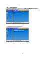
VGA Drivers Installation 1. Insert the drivers DVD that comes with the board. Click AMD, then AMD A70M Chipset Drivers.
2. Click AMD A70M Series Graphics Drivers.
3. When the welcome screen appears, click Next.
43
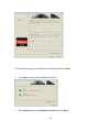
4. Select the language you would like to be displayed and click Next.
5.
Click Next to continue the installation process.
6.
Select Express and the installation location and click Next.
44
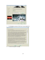
7.
Click Accept to accept the End User License Agreement.
8.
To reboot the system, click Yes.
45
Audio Drivers Installation 1. Insert the drivers DVD that comes with the board. Click AMD, then Realtek High Definition
Audio Driver.
2. When the Welcome screen to the InstallShield Wizard appears, click Next.
3.
InstallShield Wizard is now complete, click Finish to restart the system and for
changes to take effect.
4.
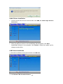
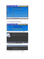
LAN Drivers Installation
1. Insert the drivers DVD that comes with the board. Click LAN Card.
2. Click Realtek LAN Controller Drivers
46
3. Click Realtek RTL8111E LANDrivers.
4. When the Welcome screen appears, click Next.
5. Now click Install to begin the installation.
6. InstallShield Wizard is complete. Click Finish.
47
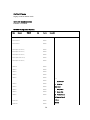
Appendix
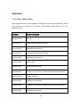
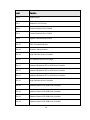
A. I/O Port Address Map
Each peripheral device in the system is assigned a set of I/O port addresses, which
also becomes the identity of the device. The following table lists the I/O port
addresses used.
Address
Device Description
0000h-0CF7h
PCI bus
0000h-0CF7h
Direct memory access controller
0010h-001Fh
Motherboard resources
0020h-0021h
Programmable interrupt controller
0022h-003Fh
Motherboard resources
0040h-0043h
System timer
0044h-005Fh
Motherboard resources
0060h-0060h
Standard 101/102-Key or Microsoft Natural PS/2 Keyboard
0061h-0061h
System speaker
0062h-0063h
Motherboard resources
0064h-0064h
Standard 101/102-Key or Microsoft Natural PS/2 Keyboard
0065h-006Fh
Motherboard resources
48
0070h-0073h
System CMOS/real time clock
0074h-007Fh
Motherboard resources
0080h-0090h
Direct memory access controller
0091h-0093h
Motherboard resources
0094h-009Fh
Direct memory access controller
00A0h-00A1h
Programmable interrupt controller
00A2h-00BFh
Motherboard resources
00C0h-00DFh
Direct memory access controller
00E0h-00EFh
Motherboard resources
00F0h-00FFh
Numeric data processor
0170h-0177h
Secondary IDE Channel
01F0h-01F7h
Primary IDE Channel
0274h-0277h
ISAPNP Read Data Port
0279h-0279h
ISAPNP Read Data Port
03F8H-03FFFh
Communications Port (COM1)
B. Interrupt Request Lines (IRQ)
Peripheral devices use interrupt request lines to notify CPU for the service required.
The following table shows the IRQ used by the devices on board.
49
Level
Function
IRQ 0
System timer
IRQ 1
Standard 101/102-Key
IRQ 3
Communications Port (COM2)
IRQ 4
Communications Port (COM1)
IRQ 8
System CMOS/real time clock
IRQ 12
PS/2 Compatible Mouse
IRQ 13
Numeric data processor
IRQ 16
High Definition Audio Controller
IRQ 16
PCI standard PCI-to-PCI bridge
IRQ 17
Standard Enhanced PCI to USB Host Controller
IRQ 17
Standard Enhanced PCI to USB Host Controller
IRQ 17
Standard Enhanced PCI to USB Host Controller
IRQ 18
High Definition Audio Controller
IRQ 18
Standard Open HCD USB Host Controller
IRQ 18
Standard Open HCD USB Host Controller
IRQ 18
Standard Open HCD USB Host Controller
IRQ 18
Standard Open HCD USB Host Controller
50
IRQ 19
PCI standard PCI-to-PCI bridge
IRQ 19
AMD AHCI Compatible RAID Controller
C. Watchdog Timer Configuration
The WDT is used to generate a variety of output signals after a user programmable
count. The WDT is suitable for use in the prevention of system lock-up, such as when
software becomes trapped in a deadlock. Under these sorts of circumstances, the
timer will count to zero and the selected outputs will be driven. Under normal
circumstance, the user will restart the WDT at regular intervals before the timer counts
to zero.
SAMPLE CODE:
//--------------------------------------------------------------------------//
// THIS CODE AND INFORMATION IS PROVIDED "AS IS" WITHOUT WARRANTY OF ANY
// KIND, EITHER EXPRESSED OR IMPLIED, INCLUDING BUT NOT LIMITED TO THE
// IMPLIED WARRANTIES OF MERCHANTABILITY AND/OR FITNESS FOR A PARTICULAR
// PURPOSE.
//
//--------------------------------------------------------------------------#include <dos.h>
#include <conio.h>
#include <stdio.h>
#include <stdlib.h>
#include "6106"
//--------------------------------------------------------------------------int main (int argc, char *argv[]);
void EnableWDT(int);
void DisableWDT(void);
//--------------------------------------------------------------------------int main (int argc, char *argv[])
{
51
unsigned char bBuf;
unsigned char bTime;
char **endptr;
//
char SIO;
printf("6106 watch dog program\n");
bTime = strtol (argv[1], endptr, 10);
printf("System will reset after %d seconds\n", bTime);
if (bTime)
{
EnableWDT(bTime);
else
{
DisableWDT();
if (bTime > 0 && bTime < 256)
{
int A;
A=2;
do{
unsigned char result;
Set_6106_LD(0x08);
result=Get_6106_Reg(0xF1);
gotoxy(1,12);
printf("Timer is %i \n",result);
}while(A!=1);
}
return 0;
}
//--------------------------------------------------------------------------void EnableWDT(int interval)
{
unsigned char bBuf;
Set_6106_LD(0x08);
52
//switch to logic device 8
Set_6106_Reg(0x30, 0x01);
Set_6106_Reg(0xF1, interval);
}
//--------------------------------------------------------------------------void DisableWDT(void)
{
unsigned char bBuf;
Set_6106_LD(0x08);
//switch to logic device 7
Set_6106_Reg(0x30, 0x00);
}
//--------------------------------------------------------------------------//
// THIS CODE AND INFORMATION IS PROVIDED "AS IS" WITHOUT WARRANTY OF ANY
// KIND, EITHER EXPRESSED OR IMPLIED, INCLUDING BUT NOT LIMITED TO THE
// IMPLIED WARRANTIES OF MERCHANTABILITY AND/OR FITNESS FOR A PARTICULAR
// PURPOSE.
//
//--------------------------------------------------------------------------#include "6106.H"
#include <dos.h>
//--------------------------------------------------------------------------unsigned int 6106_BASE;
void Unlock_6106 (void);
void Lock_6106 (void);
//--------------------------------------------------------------------------unsigned int Init_6106(void)
{
unsigned int result;
unsigned char ucDid;
F81865_BASE = 0x4E;
result = 6106_BASE;
53
ucDid = Get_6106_Reg(0x20);
if (ucDid == 0x07)
//Fintek 81865
{
goto Init_Finish;
}
F81865_BASE = 0x2E;
result = 6106_BASE;
ucDid = Get_6106_Reg(0x20);
if (ucDid == 0x07)
//Fintek 81865
{
goto Init_Finish;
}
F81865_BASE = 0x00;
result = 6106_BASE;
Init_Finish:
return (result);
}
//--------------------------------------------------------------------------void Unlock_6106 (void)
{
outportb(6106_INDEX_PORT, 6106_UNLOCK);
54
outportb(6106_INDEX_PORT, 6106_UNLOCK);
}
//--------------------------------------------------------------------------void Lock_6106 (void)
{
outportb(6106_INDEX_PORT, 6106_LOCK);
}
//--------------------------------------------------------------------------void Set_6106_LD( unsigned char LD)
{
Unlock_6106();
outportb(6106_INDEX_PORT, 6106_REG_LD);
outportb(6106_DATA_PORT, LD);
Lock_6106();
}
//--------------------------------------------------------------------------void Set_6106_Reg( unsigned char REG, unsigned char DATA)
{
Unlock_6106();
outportb(6106_INDEX_PORT, REG);
outportb(6106_DATA_PORT, DATA);
Lock_6106();
}
//--------------------------------------------------------------------------unsigned char Get_6106_Reg(unsigned char REG)
{
unsigned char Result;
Unlock_6106();
outportb(6106_INDEX_PORT, REG);
Result = inportb(6106_DATA_PORT);
Lock_6106();
return Result;
}
//---------------------------------------------------------------------------
55