1
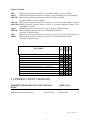
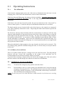
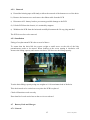
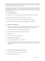
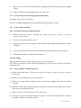
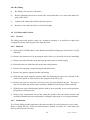
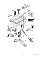
WISPA 200 & 300 SERIES Mk2
CEILING MOUNTED ELECTRIC HOIST
SERVICE MANUAL
Issue 2 July 2004
CONTENTS:
1. Introduction.
2. Operating Instructions
3. Routine Maintenance.
4. Servicing and Repair.
5. Troubleshooting
6. Electrical Circuit Diagram
7. Load testing
8. Spare Parts
9. Appendix
2
Issue 2 July 2004
This manual is a controlled document loaned by Chiltern Invadex Ltd for the sole use of
approved personnel who have attended the Chiltern Invadex training course on this
product.
It must not be copied in whole or part and it remains the property of Chiltern Invadex
Ltd.
Preface
Read and understand this manual before attempting to service or repair the hoist.
Warnings, Cautions and Notes
WARNINGS given in this manual identify possible hazards in procedures or conditions
which, if not correctly followed, could result in loss of life or severe personal injury.
Cautions given in this manual identify procedures or conditions which, if not correctly
followed, could result in equipment damage.
Notes given in this manual are used to explain or amplify a procedure or condition.
General Warnings
WARNINGS
Heavy equipment hazard. Many components and sub-assemblies of the equipment are heavy
and appropriate precautions must be taken.
Lethal voltage. Some of the given procedures, if not correctly followed, could expose live,
unprotected metal parts or conductors at potentially lethal voltage. Exercise extreme caution.
Lead-acid batteries are a potential environmental and health hazard.
Store batteries in accordance with manufacturer’s instructions.
Dispose of unserviceable batteries safely in accordance with Local Authority regulations.
The installation must be carried out by a competent person and be in accordance with the
relevant requirements of local Building Regulations and Health and Safety at Work etc. Act
1974 and associated regulations
All electrical work must be carried out by a competent electrical engineer in accordance with
the current edition of IEE Wiring Regulations or local regulations that are in force.
3
Issue 2 July 2004
1.1 Introduction.
The new Wispa range of hoists is designed to improve the independence of the disabled
person, especially in the home, and some models may be operated without assistance.
Using an appropriate sling, the overhead hoist will raise the user from a bed or wheelchair
and transport them to the bath or toilet where the hoist will lower them under their own
control.
One of the unique features of the new Wispa ceiling mounted hoists is the introduction of the
solid state electronics, which provide soft start and stop as well as speed control.
The 200 series hoists have a Maximum Load of 200Kgs (31 stone) (440lb)
The 300P series hoists have a Maximum Load of 272Kgs (42 stone) (598lb)
Technical Data
DIMENSIONS 200 & 300 Series
Height of unit
Width of unit
Length of unit
Distance from ceiling rail to underside of carry bar – fully raised
Carry bar width
Distance from ceiling rail to underside of carry bar – fully lowered
215mm (8 ½ ins)
270mm (10 ½ ins)
420mm (16 ½ ins)
490mm (19 ¼ ins)
460mm (18 ins)
2020mm (87 ½ ins)
Lifting Range - Approximately 2020mm (87 ½ ins)
No. Lifts per Charge - 200 series - 20 (up and down cycle with max 200kg (440lb) load)
300P
12 (up and down cycle with max 272kg (598lb) load)
Overload cut out - The hoist can not lift more than 1.5 time’s maximum load
Battery voltage - 24 vdc (2 x 12 v 7Ah sealed and maintenance free)
Emergency Battery - 12vdc (1 x 12 v 1.2Ah sealed battery)
Low battery indication - Audible warning device on hoist + visual
Charging time - Maximum 6 hours
Hand control - Electronic hand control - with soft button operation and reset function
Conforms to:
CE mark complies with EC Directives
Medical Device Directive (93/42/EEC)
EMC Directive (89/336/EEC)
Low voltage Directive (73/23/EEC)
4
Issue 2 July 2004
Models Available
300P
200LTX
FEATURES
200LT
Battery powered, powered lift only - max load 200kg (31 stone) (440lb)
Battery powered, powered traverse and lift - max load 200kg (31 stone) (440lb)
Battery powered, powered traverse and lift Infra-Red controls –
max load 200kg (31 stone) (440lb)
200LTX Battery powered, powered traverse, lift & x-y system - max load 200kg (31 stone)
200LTXR Battery powered, powered traverse, lift & x-y system Infra-Red controls- max
load 200kg (31 stone)
300PT
Battery powered, powered traverse, lift - max load 272kg (42 stone)
300PTR Battery powered, powered traverse, lift Infra-Red controls –
max load 272kg (42 stone)
300P
Battery powered, powered traverse, lift & x-y system - max load 272kg (42 stone)
300PR
Battery powered, powered traverse, lift & x-y system Infra-Red controlsmax load 272kg (42 stone)
200L
200L
200LT
200LTR
POWERED TRAVERSING
CORDLESS BATTERY OPERATION
EMERGENCY LOWERING
200kgs MAXIMUM LOAD
300kgs MAXIMUM LOAD
LOW BATTERY WARNING INDICATOR
COMPATABLE WITH MANUAL X – Y SYSTEM
COMPATABLE WITH POWER X – Y SYSTEM
COMPATABLE WITH TURNTABLE
EMERGENCY STOP
1.2 PRODUCTION CHANGES
MODIFICATION/ REASON FOR CHANGE
DATE
SERIAL No.
Introduction of new Mk2 hoists
H04-02-0001
February 2004
5
Issue 2 July 2004
2.1
2.1.1
Operating Instructions
For all models.
Check that the charging light on the side of the hoist is illuminated when the hoist is in the
charging point, if not refer to the maintenance section of these instructions.
Check the sling and lifting tape for fraying or broken stitching. Select the appropriate sling
and position it around the individual (refer to the sling instructions if this procedure is
unfamiliar)
If the hoist is not used for at least 20 seconds, the processor shuts down into “sleep mode” to
conserve battery power. To wake the hoist press and handset button then use as normal
The hand controls uses an electrical cable to the hoist, however, the controls are waterproof,
even when completely immersed in water. Depressing the hand control buttons operates the
hoist functions.
The lift motor will stop almost instantly when the control button is released, it will also stop
when the multi thickness of tape passes between the feed in rollers whist lifting, or when the
total length of tape has played out when lowering. The tape will normally be long enough to
lift someone from the floor. As you start to lift the individual, ensure that the sling is secure
and the individual is comfortable. If not, lower the individual and re-position the sling. It is
important to lift the client with the lifting tape in a vertical position and not at an angle which
may operate the limit switches.
When the individual is high enough to clear any obstacles, the hoist can be traversed. The
user should gently guide the individual along the track, it will run easily on its nylon wheels
in the track.
2.1.2 All Battery Powered Hoists
These are cordless models and have a charger unit at one end of the track. The fully charged
batteries will give several lifts, depending on the weight of the individual, but it's
recommended to leave the hoist on charge whenever possible.
To put the hoist on charge, simply traverse the hoist to the charging end of the track, and as
the hoist connects with the charger, the indicator on the hoist will illuminate.
2.2
2.2.1)
EMERGENCY STOP & LOWERING
To activate the emergency stop, pull the cord and release.
2.2.2)
In the unlikely event of a power failure, the individual can be lowered using the
emergency lowering pull cord. The individual may be lowered, whilst suspended
in the sling, pull the cord gently, a click will be heard, followed by a second click.
This will activate the emergency lowering.
NOTE: The descent speed is less than half that it would normally be if the hoist were working
correctly.
6
Issue 2 July 2004
2.2.3)
If the emergency lowering has been operated, pull the red cord toggle attached to
the cord firmly to reset the emergency stop switch. This is located on the top
cover of the hoist,. Press the red reset button, located on the handset of the hoist,
and three bleeps should be heard when the hoist is reset and ready to use.
3.1
Routine Maintenance.
3.1.1 The Hoist Service Sheet
A typical hoist service sheet is shown in the appendix, this shows an example of the
information required forming a service record or database. The purpose of this sheet is to
retrieve as much information about the hoist installation with a quick reference checklist.
When servicing hoists in large numbers you may be asked to service all types and make of
hoist, this is why the hoist service sheet covers all aspects of hoist servicing. There are 39
checks listed, however this report is used for overhead and mobile hoists, so some of these
checks do not apply to all hoists, which have to be carried out during a biannual or annual
hoist service. Each check has been abbreviated to keywords to jog the mind of the
experienced service engineer, if further instructions are required refer to "The Check List
Explained". This provides an in depth technical support relating to all servicing, repairs and
maintenance.
When carrying out any type of servicing to a hoist, the first action is a visual inspection of all
mechanical fixings to ensure they tight and secure. The outer casing must always be removed
for a closer inspection, and to bear in mind that any component part must last until the next
service.
A load test should be carried out using at least 100% of the safe working load. An example
of a hoist and lift test certificate is shown in the appendix.
3.1.2 An operator’s guide for checking the safety of the equipment.
a) Heavy Duty Areas: - Institutional / Hospital Utilisation
Above average activity.
Abnormal environment
(E.g. Corrosive atmospheres such as hydrotherapy pools etc.)
Heavy weight patients.
In the above case the routine maintenance should be carried out at 6 monthly intervals.
b) Light to Standard Duty areas:- Domicilary Utilisation Light to standard activity
environment and the patient's weight. In the above case the routine maintenance should be
carried out at 12 monthly intervals
Note: Lifting Operations & Lifting Equipment Regulations 1998. These regulations came into
force in December 1998. They apply to all types of lifting equipment used at work,
including patient hoists, irrespective of whether they are new, second-hand or existing items
of equipment.
Further details can be obtained from the Health and Safety Executive in a booklet called
‘Simple Guide to the Lifting Operations and Lifting Equipment Regulations 1998’.
7
Issue 2 July 2004
3.2 The Service Check List Explained
1. Carry Bar condition/cover must be tested under load with the rated capacity. Check
welds are secure, no distortion or signs of corrosion. The covers are complete and
without any splits, tears or other damage that could cause fraying to stapping etc. The
grommet fitted on the underside of the carry bar must be removed to check for nut & bolt
security. If there is not a grommet, a hole will have to be drilled in the cover and a
grommet fitted.
2. Boom Condition – Mobile Hoists only
3. Mast Condition – Mobile Hoist only
4. Leg adjustment – Mobile Hoist only
5. Castor Security - Mobile Hoist only
6. Ram/Actuator condition - Mobile Hoist only
7. Spline disengagement – Mobile Hoist only
8. On/Off switch operation – Mobile and Portable hoists only
9. Condition of Batteries – these should last for approximately 5 years if correctly
maintained, however, this is often not the case due to deep discharging and infrequent recharging.
There is no danger of over charging the batteries due to the electronic regulator circuit. It
is the job of the Installer or Service Engineer to educate the user or carer to always put the
hoist on charge when not in use. If you suspect a faulty battery, check the terminal
voltage of each battery independently and if one of the batteries is one volt or more lower
than the other battery, then it is faulty and both must be replaced. The standby/emergency
battery is also a rechargeable type on these models.
10. Transformer, Charger leads and plugs - involves inspecting to ensure that the plugs
are not damaged. Check the coiled cable from the hoist to flex outlet, ensure the correct
size of conductor has been used to prevent volt drop over long cable runs.
11. Clean & lubricate the hoist taking care not to trap any wires when replacing the cover.
Before replacing the cover, enter the details on the service card with the date and sign.
Always remove any greasy finger marks from hoist and track.
12. Carry bar fixing must be checked that welds are secure and bolts/pins are tight and
secure.
13. Brakes – Mobile Hoist only
14. Creep test pass – Mobile Hoist only
15. Correct range of travel – ensure that the hoist tape operates over its full range. All
traversing should also be checked to ensure smoothness of travel.
8
Issue 2 July 2004
16. Visual battery indicator – check operation if fitted. Wispa portable only.
17. All other indicators - ensure that the LED’s are working correctly. Green – Power on
18. Hand controls condition - Up Down and Traverse Control should be operated on and off
load.
19. Boom alignment – Mobile Hoist only
20. Mast alignment – Mobile Hoist only
21. Bumpers – Mobile Hoist only
22. Oil seals may weep one drop of oil through their lifetime, but if oil can be seen on the
inside cover, the motor gearbox should be changed.
23. Correct descent rate must be checked to see that the governor arm is free to move and
that the small extension spring has enough tension to hold the arm against the spool shaft.
Also inspect welds for penetration on pivot pin and stop.
24. Audible alarm indicator - ensure that it is working correctly when the battery voltage is
low plus other function failures
25. Max. Load labelled – this should be entered onto the service label that is attached to the
cover of the hoist to indicate the rating of the hoist and when it was last serviced and next
due. Also check that the serial number is correct with the label inside the hoist.
26. Charging rate (v) check the output voltage from the charger, which should be
approximately 36 volts off load. The charge rate can not be adjusted in any way.
27. Overall hoist condition will vary depending on the environment; if installed over
hydro/swimming pools etc. the electrical components may require additional protection
against corrosion. Hostile enviroments may dictate more frequent inspections.
28. Track & Track fixing check alignment of track, condition of moving parts (trolleys and
turntables), check all parts for corrosion especially if fitted in hydrotherapy pools and
other corrosive atmospheres. Track fixings should be inspected to see that they are tight
and secure, they may become loose if the timber strengthening beams have shrunk due to
seasoning. If studding is used, check that locking nuts are present. Coach screws may
need a quarter turn to close up any gaps between brackets and plasterboard. Always
check the installation has sufficient number of bracket fixings and the spacing is no more
than 1500mm (59 inches) or a minimum of three fixings over 2500mm (8ft). Where
tracks are fixed between walls or on a gantry frame, always check the deflection is not
greater than the specified figure given on the chart in the appendix. Finally, check all the
Allen cap screws that secure the fixing bracket to the track are tight. Use a torque wrench
to a setting of 10Nm.
9
Issue 2 July 2004
29. End stops are one of the most important safety aspects of any installation. If you need to
remove the hoist from the track for repairs, and then refit, Never forget to replace the stop
end as someone's life could depend on it. Check the bolts are tight with a 13mm socket
torque wrench to a figure of 26Nm and traverse the hoist into both end stops. The plastic
hook-up block should never be relied on as an end stop, do not to over tighten these bolts
securing the hook-up block. Some installers fit a safety pin through the track as an added
precaution.
30. Trolley bearings/nuts. Trolley Bearings rarely require lubrication as they are greased
when assembled from new. However, if a bearing becomes dry and starts to squeak then
a few drops of light oil applied in between the drive wheel and bearing housing will cure
the problem. Both the driven and non- driven trolleys are sealed units and are
maintenance free. Trolley securing nuts must be inspected to ensure that they are tight
and that half nuts and lock nuts have been fitted. Check the tension of the nut and bolt
securing the traverse unit to the chassis and that the trolley sets are both in line with each
other, as this will affect the traversing operation through the bends.
31. Traverse motor/drive - The traverse motor and gearbox is a sealed unit, which requires
no attention.
Traverse Drive mechanism consists of an endless 6mm chain being driven by a 10-tooth
sprocket on the motor and a 12-tooth sprocket on the drive shaft. Check the traverse drive
on load through the bends. Check condition of wheels and replace if required also all
nuts and bolts, roll pins etc. are tight and in the correct position.
32. Gear/chain lubrication - Chain Lubrication is most important, especially in warm humid
installations. Use multi-purpose grease applied to chain and sprockets in liberal
quantities. Also, check chain tension is tight, 1-2mm maximum play allowed.
33. Motor fixings should be checked for tightness, also pay attention to the motor and
gearbox shaft support bearing bracket is secure to chassis.
34. Wiring internal/mains should be inspected to see that a minimum of 2.5mm2 twin flat
and earth cable has been installed together with a fused spur rated at 5 amps. For free
standing gantries ensure that a 5-amp fuse is installed in the plug. NOTE: - Consult the
current local wiring regulations for the correct protection.
35. Lifting tape wear can vary depending on application, but it is recommended that it
should be changed every other service or approximately every 2 years. A worn tape
should be renewed regardless of age.
36. Condition of slings must be checked for pulled stitching where loops attached to the net
and polyester fabric. Always check slings are compatible with the carry bar. Check the
straps for damage or wear.
37. Emergency lowering must be tested with the load attached, raise the load pressing the up
button and lower by pulling the cord to it’s fullest extent. The emergency battery is
constantly being charged and should not require replacement for a number of years. To
reset pull the red toggle upwards, located on the side of the top cover, to its fullest extent
then press the reset button on the handset and release, three beeps should be heard when
its ready for use again.
10
Issue 2 July 2004
38. Limit switches Up Limit Switch should be checked on and off load. Ensure that the up
limit switch operates as the triple thickness area of tape enters the feed in rollers. Also
check the rollers are not worn on the internal clearance hole, as this will affect the
operation of the up limit switch settings. Replace main roller and bolt if in any doubt.
Down Limit Switch should be checked off load. Operate the down function and run all of
the tape off the spool until the down limit switch operates.
39. Emergency stop should be checked for correct operation. To re-set the switch, pull the
cord with a red toggle upwards, located on the top cover of the hoist, firmly to re-set the
switch. Press the reset button and release, located on the handset, and three beeps should
be heard when its ready for use again.
40. Proof tested to maximum load by lifting at least 100% of the maximum load. Raise the
weight to the up limit and lower to within 50mm (2”) of the floor, traverse the hoist along
the track to either end. If the hoist completes this test successfully a Hoist test certificate
form must be completed.
AFTER THE SERVICE HAS BEEN CARRIED OUT, THE CUSTOMER OR
AUTHORITY MAY REQUIRE A SIGNATURE OF ACCEPTANCE FROM THE
END USER.
3.3
SERVICE AND REPAIR RECORD CARD
The Service and Repair record card is stored within a PVC wallet, which is located on the
control, panel, under the hoist cover.
All details are to be completed by the hoist Installer/Service engineer
After carrying out proof testing, the installer or tester must then sign and date the card.
All service and repairs made to the hoist, must be entered, giving brief description of the fault
and any spare parts that may have been fitted.
The purpose of keeping a service record is to enable whether regular servicing is being carried
out, and also to indicate to the service engineer what work has been carried out in the past and
by whom.
4. Servicing and Repair
4.1
General
a)
This section gives information and procedures for the removal and installation of
replacement parts and sub-assemblies. Setting up procedures, which may be necessary
following component replacement, are included.
b)
Minor procedures, which may be deemed self-evident, have not been included.
c)
Do not dismantle more than necessary to replace a defective item
11
Issue 2 July 2004
d)
Before removing any electric wire, make a note of its position and identification to
assist re-assembly.
e)
Always remove all of the main battery leads before working on the hoist.
f)
When re-assembling check the condition and security of other parts ad ensure the hoist
is always left clean and safe to use.
4.2
Spreader Arm (Carry Bar)
4.2.1 Removal
a)
Pull off the swivel cover from the spreader arm hitch pin. If this is tight, use a small
screwdriver or other suitable tool to lever it off.
b)
Remove one of the key rings from the hitch pin. Support the spreader bar, push out the
hitch pin and remove the spreader bar and the cover from the lifting tape.
4.2.2 Installation
a)
Fit key ring to one end of the hitch pin. Pass the moulded cover onto the lifting tape.
Align the loop in the end of the tape between the holes of the bracket on the spreader
bar and insert the hitch pin. Fit the second key ring to the hitch pin to secure.
b)
Pull down the moulded cover until it covers the entire bracket on the spreader bar.
4.3
Lifting Tape
4.3.1 Removal
a)
Remove the spreader bar as described in paragraph 4.2.1
b)
Operate the LOWER push button and pull out the lifting tape until it is fully unwound.
c)
Disconnect the handset cord plug from the bottom case
d)
Remove the leads from the main battery to isolate the supply
e)
Slacken the tape spool grub screw and slide the spool along the shaft to gain access to
the clevis split pin
f)
Remove the split pin from the end of the clevis pin, which is located through the tape
spool and with draw the pin. The tape is now free from the spool and is carefully
withdrawn from the hoist.
12
Issue 2 July 2004
4.3.2
Installation
a)
Identify the spool end of the lifting tape, the weight limit label is nearest the spreader
bar end.
b)
Install the tape on the spool by passing the end of the tape through the limit switch
roller and aligning the loop with the hole in the side of the spool. The additional fabric
on the tape should be next to the spool for added protection.
c)
Install the tape pin through the hole in the spool and tape loop and out through the other
side of the spool drum.
d)
Fit a new split pin through the hole in the tape pin and test that the tape is secure.
e)
Slide the spool along the shaft and ensure that it aligns with the tape rollers, and tighten
the spool grub screw.
f)
Re-fit wires to the battery terminals
g)
Temporarily fit hand controls
h)
Press the up button on the handset and wind the tape onto the spool keeping tension on
the tape as it winds onto the spool to prevent it bunching up
i)
Pass the lifting tape through the slot in the cover and re-fit the spreader bar as described
in paragraph 4.2.2
4.4
Limit Switches
4.4.1 General
a)
All the limit switches are mounted on the tape roller bracket and are adjusted by
screwing sprung bolts so that they activate the micro-switch levers at the required point
as the tape passes through the roller.
b)
As the thicker part of the lifting tape passes through the rollers of the limit switch
assembly, the tape roller bracket moves and trips the upper and then the final microswitch disabling the lifting motor. The upper limit switch disables all the controls
completely. To lower the tape out of the final limit position, the emergency cord has to
be pulled to lower the tape to reset this limit switch which then allows the controls to
operate correctly.
4.4.2 Up Limit Switch Adjustment
1
In view shown below, the cut out roller is sensing only one tape thickness; the up micro
switch is normally closed and will enable the hoist to be operated up and down.
2
The up limit switch will open due to the double layer of tape between the feed rollers.
The hoist will then only operate in the down function.
13
Issue 2 July 2004
3
If the up limit switch malfunctions and therefore has opened the final limit switch, in
this situation both up and down functions are disabled. To retrieve the tape, pull the
emergency lowering cord until the single thickness of tape is visible, then press the
down button of the hand control. To rectify this fault check the up limit switch lever
adjustment, set the switch to open on the double thickness section tape. Also check the
tape rotation on the spool, if reversed the hoist operate in an opposite manner to the
hand control.
4.4.3 Down Limit Switch Adjustment
The down limit switch is also mounted on the tape roller bracket and is activated by a double
thickness of tape at the end which shuts down the lowering function of the lifting motor.
4.5
4.5.1
Main PCB
General
The PCB is basically a standard printed circuit board for all models using additional relays
and software to achieve the desired functions. The microprocessor supplied with the PCB is
programmed for the specific hoist required.
Both the lift and transverse motor and XY wiring, if fitted, are connected to the PCB by 20
pin plug.
The PCB carries out all the major control functions and no adjustments can be made.
The limit switches control the lifting motor via the PCB
The (L.E.D.) indicator light is connected to the PCB and displays a Red light when on fast
charge and a Green flashing light when on trickle charge.
14
Issue 2 July 2004
4.5.2
Removal
a) Extend the hoisting tape sufficiently to allow the removal of the bottom cover of the hoist
b) Remove the bottom cover and remove the ribbon cable from the PCB
c) Disconnect ALL battery leads to prevent any possible damage to the PCB
d) Lift the PCB from the chassis, it is retained by magnets.
e) Withdraw the PCB from the hoist and carefully disconnect the 20 way plug attached
The PCB is now free to be removed
4.5.3 Installation
Fitting of a replacement PCB is the reversal of above.
To ensure that the hoist lifts the correct weight a small screw on the side of the blue
potentiometer needs to be turned. When looking at the screw turning it clockwise will
increase the lifting capacity and counter clockwise will decrease the lifting capacity.
Test the hoist lifting capacity using test weights to 110% maximum load of the hoist.
This check needs to be carried out every time the PCB is replaced
Check all functions work correctly
Enter details of work carried out on the service record card
4.7
Battery Pack and Charger
4.7.1 General
15
Issue 2 July 2004
The 200/300 series hosts have two 12-volt 7Ah lead acid batteries to supply the power for the
lifting motor and in some models the traversing motor as well. These batteries are re-charged
by a transformer mounted at one end of the track.
The charger is mounted at one end of the track and is connected to the hoist via a beak to
allow charging of the batteries. Note: If testing the output from the charger off load, it may
read between 32v to 39v DC but when under normal charging load the voltage will stabilise
to approximately 26v DC
4.7.2
Main Battery Removal
a) Unclip the bottom cover by pressing in the side of the case and remove from the hoist.
b) Disconnect all the leads from the batteries to isolate power supply
c) Slacken the two screws on the chassis plate that hold the battery strap in place.
d) Carefully slide one of the batteries out of the strap and then the second battery.
4.7.3
Main Battery Replacement
a)
Position one of the batteries on the battery strap and then add another, ensure that the
terminals are inward facing and at the furthest point away from the reset switch
b)
Secure the batteries with the battery clamp and the two screws
c)
Re-connect the wiring to the correct terminals on the batteries
d)
Refit the base plate
e)
Refit cover, handset control cable and test
4.7.4
Back up battery replacement
a)
This is a single rechargeable 12v 1.2Ahr battery
b)
To replace the back up battery carry out the same instructions as for the main battery
pack except slacken the clamp plate for the back up battery, remove and replace with a
new battery.
4.7.5
Track Charger Unit/Charging Socket Removal
a)
Switch off and isolate the mains supply to the charger
b)
Disconnect wiring from spur socket
16
Issue 2 July 2004
c)
Remove track end cover and slacken the retaining bolts on the end stop and charging
socket
d)
Slide the end stop and charging socket out of the track
4.7.5
Track Charger Unit/Charging Socket Re-Fitting
Re-fitting is the reverse of the above.
Do not over-tighten charging socket but tighten the end stop bolts to 26Nm
4.8
Trolley Wheel Assembly
4.8.1 Non Driven Wheel Assembly Removal
a)
Remove hoist from track.
necessary precautions
Warning the weight of the hoist is heavy so take the
b)
Remove the top and bottom covers
c)
Remove the leads from the battery pack and undo the charging beak from the trolley
assembly
d)
Using a spanner undo the nylock nut and lock nut from the underside of the chassis
f)
Withdraw the trolley assembly from the chassis
4.8.2 Re-Fitting
Refitting the non-driven trolley assembly is the reverse of the above.
Care needs to be taken to ensure that the charging beak is the correct polarity to fit into the
charging socket.
4.8.3
Driven Wheel Assembly Removal
a) Remove hoist from track. Warning the weight of the hoist is heavy so take the necessary
precautions
b) Remove the top and bottom covers and remove
c) Remove the leads from the battery pack and undo the charging beak from the trolley
assembly
d) Slacken two bolts that retain the traverse motor to the chassis bracket and move the motor
to the top of the adjustment slots
e) Remove the drive chain from the traverse motor gear
f) Undo the two nylock nuts that retain the trolley to the chassis and withdraw the block
assembly complete with the drive chain
17
Issue 2 July 2004
4.8.4 Re-Fitting
a)
Re-fitting is the reverse of the above
b)
Before tightening the traverse motor bolts, ensure that there is no more than 6mm free
play on the chain
c)
Lubricate the chain with a liberal amount of grease
d)
Replace covers and test hoist over full track length
4.9 Lift Motor and Gearbox
4.9.1
General
The lifting motor and gearbox comes as a complete assembly, it is possible to replace this
component with out removing the hoist from the track.
4.9.2
Removal
a) Operate the LOWER button on the handset and pull the lifting tape down until it is fully
unwound.
b) Remove the bottom cover by pressing the ends of the cover to unclip it from the moulding
c) Remove the leads from the main and back up battery pack to isolate supply
d) Disconnect the two leads from the motor and wiring harness
e) Remove the emergency stop/lowering switch and bracket
f) Remove the gearbox support bracket and bearing
g) Slide the tape spool along the gearbox shaft, by slackening the grub screw located in the
centre of the spool, to allow access to the split pin on the clevis pin.
h) Remove the split pin from the end of the clevis pin and withdraw the pin. The tape is
now free from the spool and can be carefully withdrawn from the tape rollers and hoist.
i) With the tape spool slid along the gearbox shaft as far as possible, access can be gained to
the gearbox securing screws.
j) Remove four countersunk screws that retain the gearbox onto the chassis bracket and
carefully withdraw the motor and gearbox, sliding the tape spool as it is being withdrawn.
4.9.3 Installation
To re-fit the lifting gearbox and motor, the same procedure is carried out but in reverse order.
When re-fitting the tape, follow the instructions as detailed in section 4.3.2 and ensure the
limit switches operate correctly.
18
Issue 2 July 2004
5 Troubleshooting
Symptom
Hoist lacking power
Suggested cause
Battery power is low
Charger giving insufficient
output voltage
Red/Green light on hoist not Hoist not in charging point
working
No power
Hoist cuts out whilst lifting Twisted tape or maximum
load exceeded.
Final limit switch set too
fine
Hoist lifts when down
Lifting tape may be
button is pressed
reversed on spool
Hoist makes beeping sound
See table below
Solution
Batteries need charging
Check for increase in voltage
across main battery terminals when
hoist in put on charge.
Output voltage off load minimum
33 volts. If less change charger unit
Push hoist into charging port.
Ensure power is switched on
Ensure tape is not twisted. Check
weight on hoist.
If hoist is bleeping see table below
Adjust final limit switch
Unwind tape fully whilst pulling
gently on tape. When cut-out
operates, press the up button to
wind tape correctly
See table below
Possible fault
Hoist: Audible Beeps
1
Power up and self-test, hoist OK
3 Beeps, no repeat
2
Weight overload
1 Beep + LED flashes RED
3
Low backup battery (less than 11v)
2 Beeps + LED flashes RED
4
Low main 12v battery (less than 11v)
3 Beeps + LED flashes RED
5
Low main 24v battery (less than 23v more than 9v)
4 Beeps + LED flashes RED
All bleeping sequences are initiated by the pressing of a button on the hand control. Each
sequence of beeps will be followed by a pause and repeated for a 20 second period.
If the hoist is not used for at least 20 seconds, the processor shuts down into “sleep mode” to
conserve battery power. To wake the hoist press and handset button then use as normal
-------------It has come to our attention recently that with the new PCB in the 200/300 hoist it is possible
to flatten the batteries quite quickly under certain circumstances.
Namely when the hoist is left docked in the charger and the off switch is pulled.
The hoist sees the charge voltage and continues to cause the LED to flash, this uses some
power from the top battery. Unfortunately because the hoist is switched off the batteries are
not re-charged. Consequently this top battery can be completely flattened by the LED.
The following advice applies mainly to new installations, especially where the hoists are
installed some period before the premises are occupied.
19
Issue 2 July 2004
•
Any hoists installed on site should be left switched on, especially if they are docked
in the charge position.
•
If there is no power provided to the charger the hoist will simply go to sleep and can
remain that way for a very long time. When power is re-established to the charger the
hoist will simply receive a charge and indicate its charge status.
•
If the hoist is left away from the charge position, again it will simply go to sleep.
While the hoist is asleep minimal charge is lost.
•
For extremely extended periods before use, it may be advisable to disconnect all
batteries and carry out a commissioning visit.
Modifications to the software are under evaluation so that the hoist will alarm in these
circumstances.
Alterations to the wiring loom are also being tested that will mean when the emergency cord
is pulled the negative feed is interrupted instead of the positive which will remove the
possibility of battery draining.
6.
Electrical Circuit Diagram
SEE ATTACHED DIAGRAME
7 Load Testing
All installations should be proof load tested to at least 110% of its maximum load along the
entire track length to ensure that the installation is safe.
Normal servicing tests should only require tests to 100% maximum load.
To carry out this test, a weight of at least 200kg (440lb) for the 200 series hoist or 272kg
(598lb) for the 300 series hoist is attached to the tape. Raise the weight to the up limit and
lower to within 50mm (2”) of the floor, traverse the hoist along the track to either end. If the
hoist completes this test successfully a Hoist Test certificate must be completed.
SEE TECHNICAL BULLETIN 99
20
Issue 2 July 2004
8.0 200 & 300 series Parts List Mk2 only
ITEM No.
DESCRIPTION
QTY
1
2
3
3A
4
6
6a
8
9
10
10A
11
12
13
13A
13B
14
14A
15
15A
16
16A
17
18
19
20
Not Shown
Not Shown
Not Shown
Not Shown
Not Shown
Not Shown
Not Shown
Not Shown
Not Shown
Not Shown
Not Shown
Not Shown
Not Shown
Not Shown
Not Shown
Not Shown
Hoist main cover - 2 part
Charging Neon
Mk111 Driven Trolley Assembly
Non Driven Trolley Assembly
Hook-up beak assembly
300 series charger & block assembly
300 series charger only
Red Emergency lowering pull cord
Sealed battery 12 volt 7Ah
Wiring loom - 200 + 300 series
Retro Wiring loom - 200 + 300 series
Emergency lowering battery 12v 1.2Ah
Main PCB with ribbon cable – All Hoists
3 Button hand control – Lift only models
5 Button hand control – Lift and Traverse models
7 Button hand control - X-Y models
Carry bar – All models
Carry bar cotter pin and rings
Carry bar swivel cover - Green 200 series hoist
Carry bar swivel cover - Red 300 series hoist
Lifting tape (200kg) x 2600mm
Lifting tape (300kg) x 2600mm
Micro switch Bracket c/w micro switches
Micro switch screw block
Hoist motor/gearbox
Traverse Motor assembly
Fuse carrier
Fuse 15 amp quick-blow
Clevis pin M6 x 35
Split Pin
Infra-Red Receiver PCB
Infra-Red Handset
Chassis - 200L
Chassis - 200LT & LTX
Direction Labels
Switch - Emergency Stop/Lower
Straight Carry Bar
Retro Kit – Monosis to Amrac PCB’s – 3 Buttons
Retro Kit – Monosis to Amrac PCB’s – 5 Buttons
Retro Kit – Monosis to Amrac PCB’s – 7 Buttons
Retro Kit – Infra Red controls
User Guide 200/300 series Hoist
1
1
1
1
1
1
1
1
2
1
1
1
1
1
1
1
1
1
1
1
1
1
1
1
1
1
1
1
1
1
1
1
1
1
1
1
1
1
1
1
1
1
21
PART No.
300-90030
COM1529
300-90011
300-90010
OH131/360
300-90020
OH0635
OH0466
MHWMES30
300-00206
300-00221
COM1514
300-00220
300-00042-CI
300-00043-CI
300-00044-CI
OHCBAR1
OHHS022
OH0630-2
OH0630-1
300-00035
300-00072
300-00027
300-00032
OHO636
OH0637
COM1521
COM1520
300-00011
COM1228
300-00223
300-00123
300-90002
300-90001
300-00070
COM1528
OHCBARST
300-80001
300-80002
300-80003
300-80004
OH0652
Issue 2 July 2004
22
Issue 2 July 2004
9. Appendix
a. Battery Voltages
23
Issue 2 July 2004
BATTERY VOLTAGES and ALARMS
Mk2 200/300 Series Overhead Hoist
Here are the MINIMUM voltages when the alarms start:
22volts = Low main battery alarm – Hoist continues to operate (4 bleeps)
18volts = Hoist stops completely (4 bleeps)
11volts = Back up battery Low voltage alarm (2 bleeps)
ALL VOLTAGE CHECKS MUST BE TAKEN OFF CHARGE
As you can see that if the batteries are 12.3 volts each x 2 = 24.6 volts which is
getting near the magic 22 volt limit
The low batteries may be caused by the length of time they are in transit and/or
storage without getting a charge.
You should check the voltages when the hoist is stationary and when the hoist is
working as there may be a faulty cell in one of the batteries.
If this is the case, you should see the voltage drop below 22 volts when you try to
operate the hoist.
24
Issue 2 July 2004