1
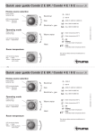
USER MANUAL
Phoenix Combi 12/1000/50
Phoenix Combi 12/1600/75
Phoenix Combi 24/1200/30
Phoenix Combi 24/2000/50
Manual
3
INTRODUCTION
Victron Energie has acquired international fame in the field of developing and
producing electrical power supply systems. Thanks to the constant efforts of the
development department in particular, Victron Energie obtain this world fame.
This department is involved in research into and execution of facilities for
implementing new technologies that can make significant technical and
economic contributions to Victron Energie products.
This proven philosophy has resulted in the development of a complete series of
power supply equipment incorporating the latest technical developments.
Victron Energie equipment meets the most stringent standards and regulations.
The range of high quality, dependable Inverters and Battery Chargers produced
by Victron Energie can be used to generate 230Vac power in places where no
permanent connection to mains electricity is available.
By using Victron Energie’s products, an automatic 'stand-alone' power system
can be created. Chosing the ‘Phoenix Combi’ in addition to powerful batteries
for this type of system is often an ideal solution. The Phoenix Combi consists of
a fully automatic battery charger, a sine-wave inverter and an automatic
switchover device.
Victron Energie equipment is suitable for all types of electrical equipment for
domestic, industrial and specialist use, including instruments susceptible to
interference. Victron Energie systems are high quality energy sources that
guarantee fault-free operation.
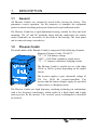
Phoenix Combi
This manual describes the installation, operation and the practical use of the
Phoenix Combi. This manual also provides information about protection devices
and the technical specifications of the Phoenix Combi.
Manual
5
CONTENTS
1.
DESCRIPTION ............................................................ 8
1.1
1.2
1.3
1.3.1
1.3.2
1.4
1.5
1.6
2.
PROTECTION DEVICES........................................... 13
2.1
2.2
2.3
2.4
2.6
2.7
2.8
2.9
3.
Start up power........................................................................ 13
Temperature protection.......................................................... 13
Low battery voltage protection ............................................... 13
High battery voltage protection............................................... 13
Ripple voltage protection ....................................................... 14
Current protection .................................................................. 14
Start-up battery protection...................................................... 15
Voltage sense protection........................................................ 15
INSTALLATION AND CONNECTION........................ 16
3.1
3.2
3.2.1
3.2.2
3.3
3.4
3.5
3.6
3.7
3.8
3.8.1
3.8.2
3.8.3
3.9
4.
4.1
6
General.................................................................................... 8
Phoenix Combi ........................................................................ 8
The battery charger section...................................................... 9
Temperature sensor ........................................................ 11
Voltage sense ................................................................. 11
The inverter section ............................................................... 11
Automatic switchover ............................................................. 12
Serial interface....................................................................... 12
Location ................................................................................. 16
Requirements for installation.................................................. 16
Requisites ....................................................................... 16
Battery cables ................................................................. 17
Connection of wiring .............................................................. 17
Connection of battery cables.................................................. 18
Connection of the start-up battery .......................................... 19
Connection of 230 Vac cables................................................ 19
Connection of remote switch .................................................. 20
Connection of remote sensing................................................ 20
Connection of voltage sense ........................................... 20
Connection of temperature sensor................................... 20
Connection of serial interface.......................................... 21
Connection in parallel ............................................................ 22
Operation................................................................... 23
The battery charger section.................................................... 24
Manual
4.1.1
4.1.2
4.1.3
4.1.4
4.1.5
4.1.6
4.1.7
4.2
4.2.1
4.2.2
4.2.3
4.2.4
4.2.5
4.2.6
4.2.7
4.3
4.3.1
4.4
4.5
5.
5.1
6.
6.1
6.2
6.3
6.4
6.5
6.6
6.7
7.
7.1
7.2
7.3
The battery...................................................................... 24
Adjustment of output voltage battery charger .................. 24
Adjustment of the equalize time ...................................... 25
Permanent boost charging .............................................. 26
Intelligent start-up ........................................................... 26
Turn off the charger. ....................................................... 26
Determining the input current. ......................................... 27
The inverter section ............................................................... 28
Overload indicator........................................................... 28
Low battery voltage indicator........................................... 28
High temperature indicator .............................................. 28
Adjustment...................................................................... 29
60 Hz setting................................................................... 29
Efficiency management................................................... 29
Calculation of battery capacity ........................................ 29
The automatic switchover ...................................................... 31
Limiting input current....................................................... 31
List of settings........................................................................ 32
Maintenance .......................................................................... 32
Trouble-shooting table............................................... 33
Problem solving ..................................................................... 33
Technical specifications ............................................ 36
Inverter input.......................................................................... 36
Inverter output ....................................................................... 37
Charger input ......................................................................... 39
Charger output ....................................................................... 39
Automatic switchover ............................................................. 41
General.................................................................................. 41
Mechanical ............................................................................ 42
DRAWINGS............................................................... 43
Dimensions ............................................................................ 44
Connection diagram............................................................... 45
Parallel connection diagram................................................... 46
Manual
7
1.
DESCRIPTION
1.1
General
All Phoenix Combi’s are extensively tested before leaving the factory. This
guarantees correct operation. For the purposes of transport the equipment
packed in shock-absorbing polystyrene foam and a rigid cardboard carton.
The Phoenix Combi has a rigid aluminium housing, suitable for floor and wall
mounting. The AC and DC terminals along with the connections for remote
control (optional) are accessible via the front of the housing. The front panel
can be removed using a screwdriver.
1.2
Phoenix Combi
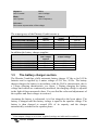
The model name of the Phoenix Combi is composed of the following elements:
Example: Phoenix Combi 12/1600/75
"12" = 12 Volt battery voltage.
"1600" = 1600 Watt continuous output power.
“75” = 75 Ampere continuous charging current.
The Phoenix Combi is suitable for use with either
12Vdc or 24Vdc systems depending on the model
chosen.
The inverter supplies a pure sinusoidal voltage of
230 Vac, 50/60 Hz (crystal-controlled). The
inverter and the battery charger supply the specified
output power or charging current.
The Phoenix Combi uses high frequency switching technology in combination
with a low frequency transformer, which results in a high output and a high
start-up power for the inverter. The ‘no-load’ power consumption is described
in section 6.
8
Manual
Ampere =
unit of current
Volt =
unit of voltage
Watt =
unit of power
Hertz =
unit of frequency
Volt rms =
Root mean square value of the voltage
The output power of the Phoenix Combi inverter is:
Model
Phoenix-Combi 12/1000/50
Phoenix-Combi 12/1600/75
Phoenix-Combi 24/1200/30
Phoenix-Combi 24/2000/50
Continuous
power
1000 W
1600 W
1200 W
2000 W
Start up
power
2300 W
4500 W
3000 W
6000 W
P30 power
1400 W
2500 W
1600 W
3000 W
In addition the battery charger supplies:
Model
Phoenix-Combi 12/1000/50
Phoenix-Combi 12/1600/75
Phoenix-Combi 24/1200/30
Phoenix-Combi 24/2000/50
1.3
Continuous
max. output
current
50 A
75 A
30 A
50 A
Continuous max.
1
output voltage
15 V
15 V
30 V
30 V
The battery charger section
The Phoenix Combi has a fully automatic battery charger 12 Vdc or for 24 Vdc
batteries and is supplied by a mains voltage of 230 Vac, 50 Hz. The battery
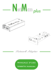
charger charges the battery in accordance with the IUoUo characteristic, this is
a 3-stage charging characteristic, see figure 1. During charging the battery
voltage and current are continuously measured, the charging voltage is adjusted
in the light of these measured values. You can find the value and adjustments of
the equalize and float voltages in section 6.
Assuming the battery is exhausted, it is first charged in the boost phase. The
battery is charged until the battery voltage is equal to the equalize voltage. The
battery is then charged to around 80% of its capacity and the charger
automatically switches to the equalize phase.
1
If the output voltage is set to this, standard settings are indicated in section 6.
Manual
9
If the voltage of the connected battery is lower than 8 Vdc respectively 16 Vdc,
the mains voltage must be at least 200 Vac to be able to start up the charger.
In the equalize phase the charging voltage remains constant, but the charging
current gradually falls. The duration of this phase can be set to 0, 2, 4 or 8
hours. The standard setting of the equalize phase is 4 hours. As soon as this
time has elapsed the charger automatically switches over to the float phase.
In the float phase the charging voltage is equal to the float voltage and the
charging current is minimal. This phase lasts 20 hours.
After the float phase the charger switches back to the equalize phase for 30
minutes. During this time the battery is briefly charged to compensate for the
internal losses of the battery.
The charger can be left connected to the battery for a long time, without gas
formation occurring in the battery due to overcharging. So the battery does not
have to be disconnected from the charger during for example the winter storage
period of a ship. The charger keeps the battery in an optimum, which results in
a longer life of the battery.
boost
equalize
float
float
U
equalize
Battery voltage
Equalize voltage
Float voltage
time
Battery current I
Figure 1
time
The Phoenix Combi charger automatically switches to the boost phase as soon
as the battery voltage falls below the minimum value. Too low a battery voltage
may be caused by a load connected to the battery.
The Phoenix Combi charger has a separate connection to charge an extra
battery, for example a start-up battery (trickle charge).
10
Manual
Charging voltage V
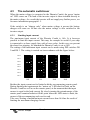
1.3.1
Temperature sensor
With the Phoenix Combi a temperature sensor is standardly supplied. This
sensor is provided with a 3 metre long cable and is intended for measuring the
temperature of the battery. If connected the charging voltage is compensated for
the battery temperature.
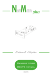
The adjustment of the battery voltage to the battery temperature is necessary to
charge the battery in the best possible way and to ensure a long lifetime. If the
battery temperature is above room
temperature the charging voltage
will fall. So with a low battery
temperature the charging voltage
will increase, after all a battery with
a low temperature may be charged
with a higher voltage. See figure 2.
Temperature °C
12 V / 24 V
14,55 / 29,10
14,25 / 28,50
13,15 / 26,30
10
20
30
40
50
60
Figure 2
1.3.2
Voltage sense
When a high current runs through the cables between the charger and the
battery there is voltage loss across the cables. The voltage, measured at the
battery poles, will then be lower than the charging voltage of the charger. As a
result it takes longer to charge the battery. For this reason the Phoenix Combi
battery charger has a Voltage sense option. The Voltage sense accurately
measures the battery voltage and increases the output voltage as soon as there is
a voltage loss over the battery cables.
The charger cannot compensate for more than 2V (for 12V) and 4V (for 24V)
of voltage loss. As soon as the voltage loss is more than 2V (for 12V), 4V (for
24V) the charging voltage will be adjusted back so that the voltage loss is a
maximum of 2V (for 12V), 4V (for 24V). When this happens the charger must
be switched off and the battery cables checked or replaced because they are too
thin or because they are incorrectly connected.
1.4
The inverter section
The inverter section has been specially developed for mains powered equipment
that depends on pure sinusoidal input voltage for effective and efficient
operation.
Manual
11
1.5
Automatic switchover
The automatic switchover operates fully automatically. When an external
230Vac mains supply is available at the input of the Phoenix Combi, this power
is used for the mains output and for operating the battery charger - see section
6 for technical specifications.
As soon as the 230 Vac input voltage is too low the inverter is immediately
switched on to continue to supply the users connected.
This switchover takes place so quickly that the users do not notice it.
The Phoenix Combi continuously checks whether there is mains voltage. If for
at least 3 seconds:
• the voltage is sufficiently high.
• the frequency is correct.
• the frequency variation is not too high (tracking rate).
the mains voltage is switched on and the inverter shuts down. Before switching
over the inverter will first synchronise itself with the mains voltage, then the
mains voltage is switched in parallel with the inverter. After this the inverter is
switched off, therefore there is no noticeable interruption of the output.
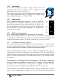
1.6
Serial interface
The Phoenix Combi can be connected to a serial databus. In combination with
an RS485 interface and the Victron Information Protocol, V.I.P.,
communication can be carried out with one or more remote panels. It is also
possible to connect several items of Victron Energie equipment to this databus.
The total of the number of units and panels that can be connected to this
databus is a maximum of 32 items. Each unit is given a unique identification
code during production so that the remote panel can read out or adjust each unit
separately.
By means of this databus and a remote panel it is then possible to change the
settings of the Phoenix Combi remotely. It is also possible to obtain information
remotely on the output voltage, current and frequency of both the battery
charger and the inverter.
12
Manual
2.
PROTECTION DEVICES
A number of protection devices are incorporated in the Phoenix Combi that
protect the unit and the equipment connected from internal electronic damage.
2.1
Start up power
The Phoenix Combi inverter can deliver a high power for short periods (see
Table in paragraph 1.2). This power is electronically limited. If the inverter is
overloaded the ‘overload’ LED will flash. If the overload is too high the
equipment will switch off and the ‘overload’ LED will stay on continuously.
After approx. 30 seconds the inverter starts up again automatically.
2.2
Temperature protection
The temperature of the electronics is continuously measured. Thanks to this
temperature monitoring the equipment is switched off if the temperature
threatens to rise too high due to shorting, overload or an extremely high
ambient temperature. The ‘temperautre’ LED will flash to indicate that the
critical temperature has almost been reached. If the internal temperature is too
high, the ‘temperautre’ LED will remain on continuously and the equipment
switches off. As soon as the temperature has fallen sufficiently, the equipment
starts up again automatically.
2.3
Low battery voltage protection
During inverter operation, as soon as the battery voltage reaches a value that is
too low the inverter is switched off. When the input voltage has risen again the
inverter comes back into operation after approx. 30 seconds.
2.4
High battery voltage protection
During inverter operation as soon as the battery voltage has reached a value that
is too high the inverter is switched off. When the input voltage has fallen again
the inverter comes back into operation after approx. 30 seconds.
Manual
13
2.5
Reverse polarity indicator
The Phoenix Combi has a reverse polarity indicator. By only fitting the fuse in a
later stage in the unit one can see whether the battery voltage offered is of the
right polarity. If the polarity is correct the fuse can be fitted and the unit is ready
for operation.
2.6
Ripple voltage protection
The Phoenix Combi is protected against a ripple voltage. Too high a ripple
voltage can be prevented both in charger and in inverter operation. Too high a
ripple voltage can be caused by a low capacity battery or by the battery cables
being too long and / or too thin. Either dynamos kan be the perpetrator of a too
high ripple voltage.
If the value of the ripple voltage on the input is high the inverter will give an
alarm; the ‘low battery’ LED and the ‘overload’ LED will flash, see section 6
for the maximum value of the ripple voltage. If the input voltage ripple is too
high or the preceding alarm situation remains for a period of 21 minutes, the
inverter will switch off and the following alarm indication can be seen; the ‘low
battery’ LED and the ‘overload’ LED will remain on continuously.
The Phoenix Combi inverter must be reset by switching it off and on again.
2.7
Current protection
The battery charger part is protected against short circuiting by means of a fuse
on the input side. If the output of the battery charger has been shorted fuse F2
might be blown. In that case first check your installation before replacing the
fuse.
The output of the inverter is also protected against shorting. The maximum
output current is electronically limited to a maximum current, see Table at
section 6.2.
14
Manual
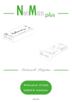
The mains voltage (when output is fed by incoming supply) is also limited by an
automatic fuse of 16 A. If this value is exceeded the fuse will break the contact.
After the fault has been removed from the installation the automatic fuse can be
switched on again by pressing the fuse button again, see figure 3.
Fuse button
Figure 3
2.8
Start-up battery protection
The output current of the start-up battery is electronically limited to 4 A.
2.9
Voltage sense protection
If the voltage drop over the battery cables is more than 2V (for 12V models) or
4V (for 24V models) the battery charger will automatically reduce the charging
voltage. In that case the “low battery” LED will flash.
If the voltage sense wires are not properly connected the charging section will
continue to work normally as if the voltage sense wires were not connected. In
this case the “low battery” LED will also flash.
Manual
15
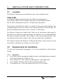
3.
INSTALLATION AND CONNECTION
3.1
Location
The Phoenix Combi must be installed in a dry, well-ventilated room.
TAKE CARE!
Too high an ambient temperature has the following consequences:
lower output, shorter life or complete shut-down of the Phoenix Combi.
See for more information section 6 (“Technical specifications”).
The housing of the Phoenix Combi is suitable for floor and wall mounting. For
mounting purposes there are holes on the bottom and back of the housing. For
the relevant dimensions please refer to section 7 (“Drawings”).
The Phoenix Combi has a built-in fan. There are no restrictions with regard to
the position in which the combi is mounted. Nonetheless it is recommended that
the unit be mounted vertically. The cooling is in fact best in this position. Take
care that the inside of the combi is also easily accessible after installation.
The distance between the Phoenix Combi and the battery must be kept as short
as possible to minimise the voltage loss in the cables.
3.2
Requirements for installation
Use the tools mentioned in paragraph 3.2.1 for the installation of the Phoenix
Combi.
3.2.1
Requisites
• Two battery cables (maximum length 6 metres) including battery terminals,
see for the diameter the Table in 3.2.2.
• A box spanner (13 mm or M8) for tightening the connecting bolts.
• A box spanner (8 mm or M5) for the connection of the fuse.
• A screwdriver (no. 2) for the connection of the 230 Vac cables.
16
Manual
3.2.2
Battery cables
The Table below shows recommended battery cables. The cross-section of the
battery cables is such that these are suitable for continuous load and peak load.
Model
Phoenix-Combi 12/1000/50
Phoenix-Combi 12/1600/75
Length 0 – 1.5 metres
Length 1.5 – 6 metres
2
35 mm
2
70 mm
2
25 mm
2
50 mm
25 mm
50 mm
Phoenix-Combi 24/1200/30
16 mm
Phoenix-Combi 24/2000/50
35 mm
2
2
2
2
Tighten the nuts firmly to prevent contact resistances.
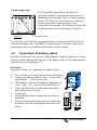
3.3
Connection of wiring
The connection of the wiring is an important step in the installation.
The connection points are located on the printed circuit board in the inverter
(see figure 4). The cable terminals are given a code ("+" or "-"). Also take good
care with the input of the charger and the output of the inverter.
Figure 4
Manual
17
Ground connection
For the ground connection the ground wire
(ground conductor) of the mains current must be
connected to the ground of the AC output terminal
block “PE” (figure 4). The circuit thus created is
however only active if the housing is also
connected to the ground. The housing is fitted with
an M4 ground screw for this purpose (figure 5).
Figure 5
Ground screw
To close the circuit, this housing ground must be connected to the ground. On
ships the housing can be "grounded" by connecting it to the ship’s hull or the
ground plate. In cars grounding can be made with the chassis.
3.4
Connection of battery cables
In order to fully utilise the capacity of the Phoenix Combi (in particular for peak
loads and when charging the batteries), only battery cables of the right thickness
must be used. See paragraph 3.2.2.
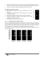
Procedure
Proceed as follows for connecting the battery cables:
•
•
•
•
•
•
•
18
Unscrew the four screws on the front of the housing.
Connect the battery cables to: the ‘+’ (red) on the
right and the ‘-‘ (black) on the left.
If the battery cables of the combi are changed over
(+ on – and – on +), the red LED will come on.
If the red LED comes on, disconnect the cables
and connect them correctly.
Fit the fuse.
Check whether all the connections are properly
tightened.
If you disconnect the battery again you must first
disconnect the other equipment connected to the
battery.
Manual
3.5
Connection of the start-up battery
The start-up battery must be connected with a cable with a core of at least 1.5
mm2.
• Connect the positive (+) battery pole to the left side of the start-up battery
connection (trickle charge), see figures 4 and 7a.
• Connect the negative (-) battery pole to the right side of the start-up battery
connection (trickle charge), see figures 4 and 7a.
3.6
Connection of 230 Vac cables
The terminal block is located on the printed circuit board (see figure 4). The
230 Vac from the harbour or mains must be connected to the Combi using a
three-core cable. Use a three-core cable with a flexible core and a cross-section
of 2.5 to 4 mm2.
Procedure
Proceed as follows for connecting the 230 Vac cables:
•
•
The 230 Vac user equipment can be connected directly to the terminal
block with the text “230 Vac –out” on the printed circuit board using a
three-core cable.
The 230 Vac mains voltage can be connected to the
terminal block with the text “230 Vac – in”. The
connection points are clearly coded. From left to
right: "PE" (ground), "N" (neutral conductor) and
“L” (phase).
Manual
19
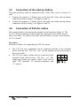
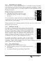
3.7
Connection of remote switch
The Phoenix Combi can be switched on and off using the remote control. If with
the remote control contact is made between “ground” and “on” then the Phoenix
Combi is in the “on” position, if contact is made between “ground” and
“charger only” then the Phoenix Combi is in the “charger only” position. (see
figure 6a and 6b).
3.8
Connection of remote sensing
Two remote sensors can be connected to the Phoenix Combi. These are the
voltage sense and the temperature sensor.
Figure 6a
Figure 6b
3.8.1
Connection of voltage sense
• Switch off the mains voltage.
• Connect a red 0.75mm2 wire between the positive battery pole and the
“+ V-sense” connector, see figure 4 and 7a.
• Connect a black 0.75mm2 wire between the negative battery pole and the
“- V-sense” connector, see figure 4 and 7a.
• Connect the mains voltage.
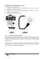
3.8.2
Connection of temperature sensor
The temperature sensor supplied can be connected to the charger with a 3 metre
long cable with stripped and tin-plated cable ends, see figure 7b. The sensor
must be mounted on the battery. The sensor regulates the charging voltage
depending on the battery temperature. This cable may have a maximum length
of 12 m.
20
Manual
Connection of the temperature sensor:
• Switch off the mains voltage.
• Connect the (-) black wire of the temperature sensor to the “- T-sense”
connector, see figure 4 and 7.
• Connect the (+) red wire of the temperature sensor to the “+ T-sense”
connector, see figure 4 and 7.
• Switch the mains voltage back on.
Figure 7b
Figure 7a
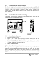
3.8.3
Connection of serial interface
The serial databus can be connected using a standard 8-pole datacable. For this
a standard 8-pole dataconnector can be used which can be connected to the
connector of the Phoenix Combi, see figure 4. This cable may have a maximum
length of 100 m.
If several units are connected to the databus connected this can be done using a
simple splitter box. Equipment connected to the databus and not switched on
has no effect on the operation of the databus.
Manual
21
Pinning of the 8-pole data cable:
Pin no.
Description
1 NC
Not connected
2 +Vdc_out
Positive supply voltage for a remote panel
3 Ground
Ground
4 Data_ser_A
Serial dataline A
5 Data_ser_B
Serial dataline B
6 R_Standby
Remote standby
7 NC
Not connected
8 NC
Not connected
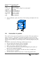
•
3.9
After installation replace the front of the housing and tighten the four
screws.
Connection in parallel
This combi can be connected in parallel to several units of the same model, see
figure at section 7.3. This makes it possible and simple to increase the load
capacity. To accomplish this, a connection is made between the devices using a
special cable provided by Victron Energie with a connecting diagram (ask your
dealer).
For parallel connections the following conditions must be met:
• Do not connect more than five devices in parallel.
• Connect only devices of the same type in parallel.
• Make sure you have sufficient battery capacity.
• The prescribed cable thicknesses should be multiplied by the number of
devices to be connected in parallel.
• Place the devices close together, but make sure there is enough space
between them for ventilation.
• Provision must be made to connect the 1,5 metre-long parallel cable.
22
Manual
4.
Operation
The switch and the LEDs are located on the front of the Phoenix Combi (see
figure 8).
Figure 8
LEDs:
mains on
boost
equalize
float
inverter on
overload
low battery
temperature
: lights up when the mains voltage is present and the switch is
set to “on”. Flashing if wall current is limited.
: lights up when the battery charger is charging in Boost
mode.
: lights up when the battery charger is charging in Equalize
mode.
: lights up when the battery charger is charging in Float
mode.
: lights up when no mains voltage is present and the switch is
set to “on”.
: lights up if too high a load is connected to the inverter.
: lights up if the battery voltage is too low.
: lights up if the inverter or charger is switched off because of
too high an ambient temperature.
on/off/charger only switch
Using the “on/off/charger only” switch the Phoenix Combi can be switched to
on, off or charger only respectively, (see figure 8).
When the switch is switched to “on” and mains voltage is present, the “mains
on” LED will remain on continuously. In that case the mains voltage is
switched to the inverter output and the battery charger comes on. Depending on
the charging mode applicable at that time the “boost”, “equalize” or “float”
LED will be on.
If no mains voltage is present then the inverter will be switched on, in that case
the “inverter on” LED will come on. If the switch is set to “charger only” the
battery charger of the Phoenix Combi will only switch on if mains voltage is
present. In that case the mains voltage is switched to the inverter output.
Manual
23
4.1
The battery charger section
The Phoenix Combi battery charger is a fully automatic charger for 12V or
24V batteries, (depending on the model) and is supplied by a mains voltage of
230 Vac, 50 Hz. The battery charger charges the battery in accordance with the
IUoUo characteristic; this is a 3-stage, fully automatic charging method. During
charging the battery voltage and current are measured continuously, the
charging voltage is adjusted in the light of these measured values.
4.1.1
The battery
Below is a Table showing the recommended battery capacity:
Model
Phoenix-Combi 12/1000/50
Phoenix-Combi 12/1600/75
Phoenix-Combi 24/1200/30
Phoenix-Combi 24/2000/50
Recommended capacity
120 - 300 Ah
300 – 600 Ah
120 – 200 Ah
200 - 400 Ah
The charging voltages of the Phoenix Combi charger are set in the factory. Most
battery manufacturers recommend these charging voltages for the optimum
charging of 12 V or 24 V lead-acid batteries.
It is possible to charge different types of batteries such as traction batteries. To
be able to charge these batteries the charging voltage of the charger must be
changed. Contact your Victron Energie dealer or your battery supplier for the
recommended charging voltages.
4.1.2
Adjustment of output voltage battery charger
24
Manual
DS 5
DS 4
7
6
DS 2
2
DS 3
5
DS 6
4
DS 7
3
DS 8
DS 1
1
Changing the float voltage:
• Remove all other loads that are connected to the output
of the charger.
• Connect the mains voltage and set the switch of the
Phoenix Combi to “Charger only”.
• Slide the DIP- switches DS6 and DS7 to the right. This
has the effect of shortening the equalize time to 0 hours,
and the charger then switches immediately to float
switches.
• Measure the float voltage with a precision voltmeter.
8
To be able to adjust the output voltage of the inverter, the housing of the
Phoenix Combi must be opened. For this unfasten the four screws on the front.
DS 5
DS 4
DS 3
DS 2
DS 1
8
7
6
DS 6
5
DS 7
4
DS 8
3
Changing the equalize voltage:
• The equalize voltage can only be adjusted with a full
battery.
• Push DIP switch DS8 to the left. The charger now switches
to permanent boost.
• Measure the equalize voltage with a precision voltmeter.
• Adjust the equalize voltage to the required value with
potentiometer R54, see figure 9.
• Push DIP switch DS8 back to the right.
2
•
Adjust the float voltage to the required value with potentiometers R53, see
figure 9. The float voltage can only be adjusted with a fully charged battery.
Correct the equalize time by pushing back DIP switch DS7.
1
•
4.1.3
Adjustment of the equalize time
The time of the equalize phase can be changed to meet the battery specifications
as far as possible. The time can be set at 0, 2, 4 or 8 hours. If 0 hours is selected
this means that the charger jumps the equalize phase and so switches directly to
the float phase. The standard setting of the equalize time is 4 hours.
The equalize time can be set by moving DIP switches DS6 and DS7 as shown in
the example below.
0 hours
2 hours
Manual
4 hours
8 hours
25
4.1.4
Permanent boost charging
When the battery is almost fully discharged, it is advisable to charge the battery
for 10 hours on boost. Do not do this with gas-tight lead-acid batteries. Contact
your Victron Energie dealer or your battery supplier for more information on the
charging of batteries.
Setting the charger to permanent boost:
• Push DIP switch DS8 to the left. In this
position the battery can only be charged
on boost.
It is not advisable to charge the battery for longer than 10 hours
on permanent boost; this can cause gas formation in the battery
which can cause serious damage.
During permanent boost charging regularly check the water level in the battery
and top this up if necessary.
7
8
DS 8
6
DS 7
5
DS 6
4
DS 5
DS 4
3
4.1.5
Intelligent start-up
If a battery is connected, the battery charger will automatically
sense the voltage of the battery and select which charging mode
to start in. If the battery voltage is below the minimum value
the battery charger will start in boost or equalize mode. If the
battery voltage is above the minimum value Vmin then the
charger will start in float mode. In this way a full battery is not
overcharged. The value of Vmin is indicated in section 6.
DS 3
1
2
DS 2
DS 1
If required, the charger can always start in boost mode,
followed by equalize mode and float mode. For this the “battery
recondition” option, DS4 is pushed to the left. Always starting in the boost
mode will limit the life of the battery.
7
8
DS 8
6
DS 7
5
DS 6
4
DS 5
DS 4
3
4.1.6
Turn off the charger.
The charger part can be turned off in two ways:
• Put DS2 and DS3 to the left. (The transfer switch will still
be working).
• Or connect a Phoenix Inverter Remote Panel (PIV).
DS 3
1
2
DS 2
DS 1
0A
26
Manual
4.1.7
Determining the input current.
If a Phoenix Combi Remote Panel (PCV) is connected, normally this will
determine the input current , regardless of the dipswitch setting. This is not the
case when the Phoenix Combi is at “ON” position and dipswitch setting at 0 A.
Figure 9
Manual
27
4.2
The inverter section
The inverter section has been specially developed for mains voltage equipment
that depends on a pure sinusoidal input voltage for effective and efficient
operation. Certain equipment does in fact only function without problems on a
sinusoidal voltage. This applies to, amongst other things, computers, equipment
for communications and precision measuring instruments.
4.2.1
Overload indicator
If the inverter becomes overloaded, the "overload" LED will flash. If the
overload is too high the inverter will automatically switch off, then the
‘overload’ LED will remain on continuously. After approx. 30 seconds the
inverter starts up again automatically.
4.2.2
Low battery voltage indicator
The “low battery” LED will flash if the battery voltage is lower than 10,9 Vdc
( at 12V ) and 21,8 Vdc ( at 24V ) and the LED lights up continuously when the
input voltage of the inverter is too low. The inverter is immediately switched off
automatically in such a case.
Too low an input voltage is caused by:
• An exhausted battery.
• A relatively low battery capacity compared with the high battery load as a
result of which the terminal voltage falls considerably.
• Battery cables too thin and/or too long.
• Poor condition of the batteries.
• Bad connections at battery or inverter.
As soon as the input voltage has risen sufficiently the Phoenix Combi starts up
again after approx. 30 seconds.
4.2.3
High temperature indicator
The Phoenix Combi has forced cooling using a fan. This fan runs at half speed
from a load of approximately 0.4x the nominal load. The speed then increases
linearly, as the load becomes greater.
In case of a high ambient temperature the "temperature" LED comes on and the
fan runs at full speed. When such a situation occurs, the Phoenix Combi is
automatically switched off. The Phoenix Combi starts up again as soon as the
temperature has fallen sufficiently.
28
Manual
DS 5
DS 4
DS 3
DS 2
7
6
5
DS 6
4
DS 7
3
DS 8
2
4.2.5
60 Hz setting
Some equipment only works correctly at 50 Hz or at 60 Hz.
The inverter of the Phoenix Combi can generate a 230 Vac
sinusoidal alternating voltage with a frequency of 50 Hz or 60
Hz. The frequency can be set at 60 Hz by moving DIP switch
DS5 to the left, see the figure alongside. As standard the
inverter is set at 50 Hz.
8
4.2.4
Adjustment
To be able to adjust the output voltage of the inverter, the
housing of the Phoenix Combi must be opened. For this
unfasten the four screws on the front.
The output voltage of the inverter is adjusted as standard to 230
Vac. Using potentiometers R52 (see figure 9) the output voltage
can be changed by approx. +5% and –20%.
1
DS 1
4.2.6
Efficiency management
In the design special attention has been paid to an extremely
low own consumption with low or absent load. As a result an economy-position
is superfluous and all small consumers such as clocks, electronic displays and
connected equipment continue to operate normally in a stand-by position.
4.2.7
Calculation of battery capacity
The required minimum battery capacity can be calculated. As a starting point
for the calculation the duration and the absorbed power of the equipment which
must be supplied using a Phoenix Combi inverter must be known.
For the calculation first make a list in which the equipment that must be
supplied using a Phoenix Combi inverter is summed up. Note for each separate
unit the absorbed power and multiply that by the time (in hours) during which
power is absorbed (Watt-hours). Count the internal loss of the Phoenix Combi
inverter here.
The internal loss is calculated from two components. If the inverter is supplying
power, the Phoenix Combi has an output of 85%. A further 15% must therefore
be added to the calculated power. If no power is supplied one must take into
account the no-load consumption of the Phoenix Combi (see section 6).
Then determine the number of ampere-hours (Ah) by dividing the absorbed
power by the nominal battery voltage (12 Volt or 24 Volt). The result of this
Manual
29
calculation gives the current consumption in ampere-hours and hence the total
consumption capacity of the battery in ampere-hours (Ah).
Multiply this value by a safety factor of 1.7. The result thus obtained indicates
the required battery capacity.
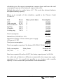
Below is an example of this calculation, applied to the Phoenix Combi
12/1600/75.
Unit
CTV
Video recorder
Hi-fi installation
Lighting
Computer
Cooking ring
Power
200 W
50 W
100 W
300 W
100 W
750 W
Duty cycle in hours
4
4
6
3
3
1
Total consumption
Consumption
800 Wh
200 Wh
600 Wh
900 Wh
300 Wh
750 Wh
3550 Wh
Internal loss (3550/85%) x 15%
Internal loss during 12 hours without power supply
(12 hours x 6.5 W)
Total power consumption
626 Wh
78 Wh
4254 Wh
Total consumption capacity of the battery (4254 Wh/ 12 Volt):354,5 Ah
Daily consumption
354,5 Ah
x
Safety factor
1.7
Required Ah
= 602,7 Ah
Based on a required Ah value of 602,7, the battery capacity must be 600 Ah.
For sealed and gel batteries a different recommended safety margin may apply,
sometimes to 1.3. As a result it is possible to use a battery with a smaller
capacity. For this consult the specifications of the manufacturer.
30
Manual
4.3
The automatic switchover
When the mains voltage is connected to the Phoenix Combi, the green “mains
on” LED comes on. The load of the inverter output is then switched directly to
the mains voltage. As a result the inverter will not supply any further power, see
for more information paragraph 1.5.
If the switch is on “charger only” when mains voltage is present the battery
charger will come on. In that case the mains voltage is also switched to the
inverter output.
0A
8
2
3
4
5
6
7
8
7
6
5
4
3
2
7
4A
10A
1
DS 1
1
1
2
DS 2
1
DS 3
2
3
DS 4
3
4
DS 5
4
5
DS 6
5
6
DS 7
6
7
8
DS 8
8
4.3.1
Limiting input current
The maximum input current of the Phoenix Combi is 16A. It is however
possible to limit the input current. This may for example be useful if your ship
is connected to a shore supply fuse with a lower value. In this way you prevent
the shore fuse tripping. As standard the Phoenix Combi is set at 16A.
The setting of the maximum input current can be made using DIP switches DS
2 and DS 3. The setting is carried out in accordance with the figure below:
16A
Besides the input current can be limited with the accompanying remote panel.
During limiting the inputcurrent the “mains on” LED starts to flash, on the
Phoenix Combi as well as on the remote panel, at the moment that the input
current is equal to the load current. By slowly turning the potentiometer of the
remote panel counterclockwise till the point where the LED starts to flash, the
current of the accompanying scale can be read.
Take care! Setting a maximum input current lower than 16A has the result of
limiting the maximum charging current.
Manual
31
List of settings
0A
4A
10 A
16 A
DS 7
DS 6
DS 5
DS 4
DS3 left
DS3 right
DS3 left
DS3 right
DS 3
DS 2
DS 1
7
DS 8
6
DS7 right
DS7 right
DS7 left
DS7 left
5
DS8 left
DS6 right
DS6 left
DS6 right
DS6 left
DS5 left
DS4 left
DS2 left
DS2 left
DS2 right
DS2 right
4
60 Hz
Battery recondition
Limiting input current
0 hours
2 hours
4 hours
8 hours
3
Permanent boost
Equalize time
8
DIP switch
2
Function
1
4.4
Standard
setting
DIP switch DS1 is not used and may be positioned either on the left or right. All
functions can be switched by moving the DIP switch to the “on”-position (to the
left). Default adjusting is all DIP switches to the right, except DS7.
4.5
Maintenance
The Phoenix Combi requires no specific maintenance. It is sufficient for all the
connections to be checked once per year. Prevent the Phoenix Combi getting
damp and keep the unit as clean as possible.
32
Manual
5.
Trouble-shooting table
Using the step-by-step plan below the commonest faults can quickly be traced.
Before tests are carried out with the inverter and/or battery charger the other 12
Vdc or 24 Vdc and 230 Vac equipment must be disconnected from the batteries
and the inverter.
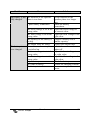
5.1
Problem solving
If the fault cannot be solved, consult your Victron Energie dealer.
Problem
Cause
Solution
The inverter
does not work
when it is
switched on.
The “low
battery” LED
flashes.
The “low
battery” LED is
on.
The “low
battery” LED
flashes.
The battery voltage is too
high or too low.
Make sure the battery
voltage is within the right
value, see paragraph 7.
The battery voltage is low.
Charge the battery or check
the battery connections.
The inverter switches off
because the battery voltage
is too low.
There is a voltage loss in
the battery cables of more
than 2 Volts.
Or the voltage sense wires
are connected back to front.
Charge the battery or check
the battery connections.
The “overload”
LED flashes.
The “overload”
LED is on.
The
“temperature”
LED flashes.
The load on the inverter is
above the nominal load.
The inverter is switched off
because the load is too high.
The ambient temperature is
high, or the temperature of
the internal components is
high or the load is too high.
Manual
Switch the charger off.
Replace the battery cables
or connect them properly.
Turn the charger off and
connect the voltage sense
wires correctly.
Disconnect part of the load.
Disconnect part of the load.
Place the inverter in a cool
and well-ventilated
environment or disconnect
part of the load.
33
Problem
The
“temperature”
LED is on.
The “low
battery” and
“overload”
LED’s flash.
The “low
battery” and
“overload”
LED’s are on.
Cause
Solution
The inverter is switched off
as a result of too high an
ambient or component
temperature or the load is
too high.
Low battery voltage and too
high a load or the ripple
voltage on the input reaches
10% of the DC value of the
input voltage.
Place the inverter in a cool
and well-ventilated
environment or disconnect
part of the load.
The inverter is switched off
as a result of too high a
ripple voltage on the input.
One alarm LED
is on and the
second flashes.
Charge the batteries,
disconnect part of the load
or fit batteries with a
higher capacity. Fit shorter
and/or thicker battery
cables. Check dynamo.
Fit a ripple-voltage
suppresser and/or batteries
with a higher capacity. Fit
shorter and/or thicker
battery cables and reset the
inverter (switch off and
back on again).
Check this table to take
action depending on the
alarm.
The inverter is switched off
as a result of the alarm of
the LED that is on. The
flashing LED indicates that
the inverter is about to be
switched off by the alarm in
question.
The charger does The value of the mains
Measure the mains voltage
not work.
voltage must be between 185 and make sure that this ends
Vac and 265 Vac.
up at between the 185 Vac
and 265 Vac.
The input fuse is faulty.
Return the unit to your
dealer.
34
Manual
Problem
Cause
The battery is not The duration of the equalize
fully charged.
phase is too short.
A poor battery connection.
The battery is
over charged.
The boost voltage is set at the
wrong value.
The float voltage is set at the
wrong value.
The capacity of the battery is
too big.
The output fuses are faulty.
The continuous boost option
is switched on.
The boost voltage is set at the
wrong value.
The float voltage is set at the
wrong value.
A poor battery.
Too small a battery.
The battery is too hot.
Manual
Solution
Set the duration of the
equalize phase to a longer
time.
Check the battery
connections.
Adjust the boost voltage to
the correct value.
Adjust the float voltage to the
right value.
Connect a battery with a
smaller capacity.
Replace the output fuses.
Switch the continuous boost
option off.
Adjust the boost voltage to
the right value.
Adjust the float voltage to the
right value.
Check the battery.
Reduce the charging current.
Connect a temperature
sensor.
35
6.
Technical specifications
6.1
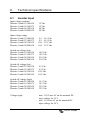
Inverter input
Input voltage nominal
Phoenix Combi 12/1000/50
Phoenix Combi 12/1600/75
Phoenix Combi 24/1200/30
Phoenix Combi 24/2000/50
Input voltage range
Phoenix Combi 12/1000/50
Phoenix Combi 12/1600/75
Phoenix Combi 24/1200/30
Phoenix Combi 24/2000/50
Switch-on voltage (low)
Phoenix Combi 12/1000/50
Phoenix Combi 12/1600/75
Phoenix Combi 24/1200/30
Phoenix Combi 24/2000/50
Switch-off voltage (low)
Phoenix Combi 12/1000/50
Phoenix Combi 12/1600/75
Phoenix Combi 24/1200/30
Phoenix Combi 24/2000/50
Switch-off voltage (high)
Phoenix Combi 12/1000/50
Phoenix Combi 12/1600/75
Phoenix Combi 24/1200/30
Phoenix Combi 24/2000/50
Voltage ripple
36
12 Vdc
12 Vdc
24 Vdc
24 Vdc
9,5 – 16,1 Vdc
9,5 – 16,1 Vdc
19,0 – 32,2 Vdc
19,0 – 32,2 Vdc
10,9 Vdc
10,9 Vdc
21,8 Vdc
21,8 Vdc
9,5 Vdc
9,5 Vdc
19,0 Vdc
19,0 Vdc
16,1 Vdc
16,1 Vdc
32,2 Vdc
32,2 Vdc
max. 1,50 Vrms AC on the nominal DC
input voltage for 12 V.
max. 3,0 Vrms AC on the nominal DC
input voltage for 24 V.
Manual
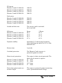
Input current nominal
Phoenix Combi 12/1000/50
Phoenix Combi 12/1600/75
Phoenix Combi 24/1200/30
Phoenix Combi 24/2000/50
100 A at 12 V/1000 W
160 A at 12 V/1600 W
60 A at 24 V/1200 W
100 A at 24 V/2000 W
Input current maximum:
Phoenix Combi 12/1000/50
Phoenix Combi 12/1600/75
Phoenix Combi 24/1200/30
Phoenix Combi 24/2000/50
200 A
400 A
150 A
300 A
Power consumption no-load:
Phoenix Combi 12/1000/50
Phoenix Combi 12/1600/75
Phoenix Combi 24/1200/30
Phoenix Combi 24/2000/50
6W
6W
8W
6W
6.2
Inverter output
Output voltage
230 Vac +/- 1 %
Output voltage range
185 Vac – 245 Vac
Frequency
50 / 60 Hz +/- 0.2 % (crystal-controlled)
Waveform output voltage
pure sinusoidal
Total harmonic distortion
maximum 5 %
Power factor (cos phi)
0.2 capacitive to 0.4 inductive
Nominal power
Phoenix Combi 12/1000/50
Phoenix Combi 12/1600/75
Phoenix Combi 24/1200/30
Phoenix Combi 24/2000/50
1000 W
1600 W
1200 W
2000 W
Manual
(cos phi = 1.0; 0ºC - +40ºC)
(cos phi = 1.0; 0ºC - +40ºC)
(cos phi = 1.0; 0ºC - +40ºC)
(cos phi = 1.0; 0ºC - +40ºC)
37
P30 power
Phoenix Combi 12/1000/50
Phoenix Combi 12/1600/75
Phoenix Combi 24/1200/30
Phoenix Combi 24/2000/50
1500 W
2500 W
1700 W
3000 W
Peak power
Phoenix Combi 12/1000/50
Phoenix Combi 12/1600/75
Phoenix Combi 24/1200/30
Phoenix Combi 24/2000/50
2250 W
4500 W
3000 W
6000 W
Switch-on behaviour
The inverter can be switched
on at any load.
Efficiency
Phoenix Combi 12/1000/50
Phoenix Combi 12/1600/75
Phoenix Combi 24/1200/30
Phoenix Combi 24/2000/50
Pnom
84 %
85 %
86 %
87 %
Dynamic stability
maximum 10 % short-term deviations
when switching on and off at 50 % of the
nominal load
Restore time
3 periods
Overload protection
The Phoenix Combi inverter is
protected against overload.
Short-circuit protection
Phoenix Combi 12/1000/50
Phoenix Combi 12/1600/75
Phoenix Combi 24/1200/30
Phoenix Combi 24/2000/50
The output is short-circuit protected. The
short-circuit current is approx.:
10 Arms
20 Arms
13,5 Arms
27 Arms
Protection against mains on
inverter output
The output is protected against connecting
a not- synchronized main voltage.
38
Manual
½Pnom
86 %
89 %
87 %
89 %
6.3
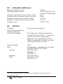
Charger input
Input voltage range
Frequency range
Maximum input current
Phoenix Combi 12/1000/50
Phoenix Combi 12/1600/75
Phoenix Combi 24/1200/30
Phoenix Combi 24/2000/50
Input fuse F2
Phoenix Combi 12/1000/50
Phoenix Combi 12/1600/75
Phoenix Combi 24/1200/30
Phoenix Combi 24/2000/50
Efficiency
Phoenix Combi 12/1000/50
Phoenix Combi 12/1600/75
Phoenix Combi 24/1200/30
Phoenix Combi 24/2000/50
Cos phi / power factor
6.4
187 – 265 Vac, full output power available
45 – 55 or 55 – 65 Hz, full output power
available
At 230Vac input voltage:
4,0 A at 15 V / 50 A
6,0 A at 15 V / 75 A
4,7 A at 30 V / 30 A
8,1 A at 30 V / 50 A
250 Vac / 10 A fast 6.3x32 mm
250 Vac / 15A fast 6.3x32 mm
250 Vac / 10 A fast 6.3x32 mm
250 Vac / 20 A fast 6.3x32 mm
81 % at 230 Vac and 15 Vdc 50 A
82 % at 230 Vac and 15 Vdc 75 A
83 % at 230 Vac and 30 Vdc 30 A
84 % at 230 Vac and 30 Vdc 50 A
1.0
Charger output
Equalize charging voltage
Phoenix Combi 12/1000/50
Phoenix Combi 12/1600/75
Phoenix Combi 24/1200/30
Phoenix Combi 24/2000/50
Float charging voltage
Phoenix Combi 12/1000/50
Phoenix Combi 12/1600/75
Phoenix Combi 24/1200/30
Phoenix Combi 24/2000/50
14.25
14.25
28.50
28.50
Vdc
Vdc
Vdc
Vdc
13.25
13.25
26.50
26.50
Vdc
Vdc
Vdc
Vdc
Manual
39
Output voltage range
Phoenix Combi 12/1000/50
Phoenix Combi 12/1600/75
Phoenix Combi 24/1200/30
Phoenix Combi 24/2000/50
Minimum voltage Vmin for
start-up in float mode
Phoenix Combi 12/1000/50
Phoenix Combi 12/1600/75
Phoenix Combi 24/1200/30
Phoenix Combi 24/2000/50
Charging characteristic
Current/voltage stability
Output current range
Phoenix Combi 12/1000/50
Phoenix Combi 12/1600/75
Phoenix Combi 24/1200/30
Phoenix Combi 24/2000/50
Maximum start-up batterycurrent
Battery leakage current,
when the battery charger is
switched off.
40
12-15
12-15
24-30
24-30
Vdc
Vdc
Vdc
Vdc
V_float - 0,75
V_float - 0,75
V_float - 1,5
V_float - 1,5
IUoUo
±1%
0-50
0-75
0-30
0-50
4
A
A
A
A
A
≤1
mA
Manual
Vdc
Vdc
Vdc
Vdc
6.5
Automatic switchover
Maximum switchover power
Maximum change up power
Switchover time from inverter to mains voltage
Switchover time from mains voltage to inverter
Switchover voltage mains voltage to inverter
Switchover voltage inverter to mains voltage
Frequency range
6.6
: 3680 W
: 3680 W (limited by 16A
Thermal Circuit Breaker)
: none2
: 20 ms
: 170 Vac
: 187 Vac
: 45 Hz – 65 Hz
General
Ventilation
Protection against too high
ambient temperatures,
overload and shorting
Forced convection (internal)
Relative humidity
EMC:
0-95%
Electromagnetic compatibility in accordance
with EMC directive 89/336 EEC:
EN 55014 (1993)
EN61000-3-2
EN61000-3-3
EN 55104 (1995)
EN 60950-4 (1991)
EN60335-2-29
Emission
Immunity
Safety
2
The temperature of critical components is
measured with sensors (PTC ’s). The combi
switches off as soon as the maximum
temperature of a component is exceeded.
When the temperature has fallen, the combi
automatically switches on again.
Because inverter and mains voltage operate in parallel for a short time there is
no switchover time.
Manual
41
6.7
Mechanical
Housing
Colour
Dimensions (h x b x d)
Weight
Phoenix Combi 12/1000/50
Phoenix Combi 12/1600/75
Phoenix Combi 24/1200/30
Phoenix Combi 24/2000/50
Connection 230 Vac
Connection 12 and 24 Vdc
External connections:
Sensing, remote switch and
Start-battery
Serial interface
42
Aluminium, protection class IP21
Blue (RAL 5012)
348 x 250 x 205
12 kg
18 kg
12 kg
18 kg
Connections to printed circuit board
(2 x connector suitable for 4 mm2 wires).
Connections to printed circuit board (M8
bolts).
Connections to printed circuit board
(connector suitable for 1.5 mm2 wires).
8-pole UTP connector
Manual
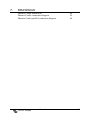
7.
DRAWINGS
Phoenix Combi dimensions
Phoenix Combi connection diagram
Phoenix Combi parallel connection diagram
Manual
44
45
46
43
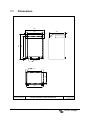
7.1
Dimensions
250
205
25
7
294
348
25
200
15
6.2 mm
25
150
8.0 mm
220
© victron energie b.v.
44
Victron Phoenix Combi dimensions
Manual
Drawing no.: PHC0000A
Date: 180399
Revision no.: 000
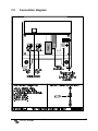
7.2
Connection diagram
Manual
45
7.3
46
Parallel connection diagram
Manual