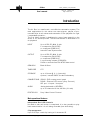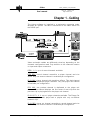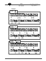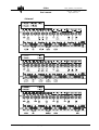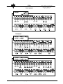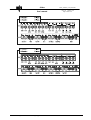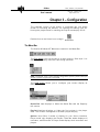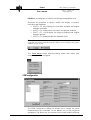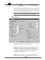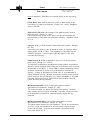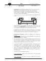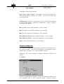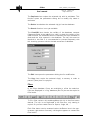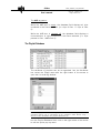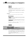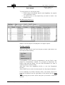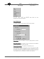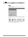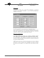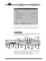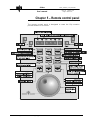
1
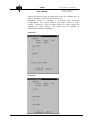
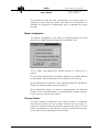
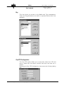
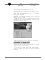
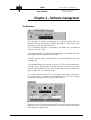
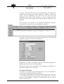
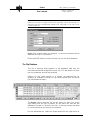
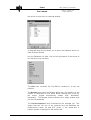
USER’S MANUAL
VERSION : 1.12a
ISSUE: 2.0 DATE : May 2001
Airbox
Airbox_Userman_1.12a_010507.doc
Issue: 1.0 Version: 1.08
Page 1 Date:21/05/01
User's manual
Introduction
The Air Box is a small-scale, cost-effective automation system. The
main applications for this server are news playout, playout of prerecorded clips in talk shows and automation of the playback for night
/ unattended operation...
The first video channel is dedicated to record new material on the
drives or for search/preview. The second channel is dedicated to on
air playback.
INPUT
Up to 4 SDI 270 MHz 10 bits
2 x composite (PAL/NTSC)
or component (RGB/YUV)
Internal Frame Synchronizer
OUTPUT
Up to 4 SDI 270 MHz 10 bits
3 x composite (PAL/NTSC)
or component (RGB/YUV)
2 x monitoring outputs (CVBS/SDI)
SVGA or monochrome PAL/NTSC data control
GENLOCK
Black & Burst
TIMECODE
LTC
STORAGE
up to 12 hours @ 6 : 1 (internally)
optional, internal RAID5 for data redundancy
CONNECTIONS RS422 - EVS remote control panel
RS422 - External VTR control (Sony Protocol)
GPI port - 4 inputs / 4 outputs
AUDIO
Analog balanced or AES/EBU,
up to 16 channels 16 bits, 48 KHz (1U rack)
PROTOCOLS
Sony Video Control Protocol
Main operational features
Independent Rec & PB channels
No need to wait until action is completed. It is also possible to play
back material while it is still being recorded (time shift delay).
Clip management
Up to 512 clips - each clip having a 16-character ID.
EVS Broadcast Equipment
Email : [email protected]
Tel: +32-4/361 70 00 FAX: +32-4/361 70 99
Airbox
User's manual
Airbox_Userman_1.12a_010507.doc
Issue: 1.0 Version: 1.08
Page 2 Date:21/05/01
Playlist management
Non-linear editing facilities such as Insert, Remove, Loop into a clip,
etc allow the operator to build the playlist. The playlist can be
modified while it is on air. The second access is always
simultaneously available for selecting some clips or recording new
ones. It can also be used to preview automatically the next clip due
to be on air in the playlist.
External VTR control (Sony protocol)
It is possible to chain material from the disks (short or medium
duration) with other material recorded on tape (longer duration) with
frame accuracy.
User-friendly interface
Customized remote panel, mouse & SVGA monitor allow a full control
of the Air Box.
EVS Broadcast Equipment
Email : [email protected]
Tel: +32-4/361 70 00 FAX: +32-4/361 70 99
Airbox
User's manual
Airbox_Userman_1.12a_010507.doc
Issue: 1.0 Version: 1.08
Page 3 Date:21/05/01
Chapter 1 - Cabling
The Airbox software is installed in a workstation operating under
Windows NT system. The data is transferred to the Video Server via
the RS232 port.
Video and audio cables are differently wired up depending on the
channels configuration used. Pay attention to the channels location
on input and output connectors.
REC 1, 2, 3: up to 4 record channels available
REC REV: record channel reversible to player channel and vice
versa. Only one reverse channel is available per configuration.
PLAY MIX: player channel with transition effects. This dual-channel
requires 2 inseparable player channels. Only one player mix channel
is available per configuration.
PRV MIX: one preview channel is dedicated to the player mix
channel. This channel displays the first frame of next clip while the
previous clip is playing back on the player mix channel.
PLAY CUT 1, 2, 3: up to 4 player channels available. The Player Cut
channel, aptly named, plays back a playlist with only cut effects
between clips.
PLAY REV: player cut channel reversible to record channel and vice
versa. Only one reverse channel is available per configuration.
EVS Broadcast Equipment
Email : [email protected]
Tel: +32-4/361 70 00 FAX: +32-4/361 70 99
Airbox
User's manual
Airbox_Userman_1.12a_010507.doc
Issue: 1.0 Version: 1.08
Page 4 Date:21/05/01
2-channel
EVS Broadcast Equipment
Email : [email protected]
Tel: +32-4/361 70 00 FAX: +32-4/361 70 99
Airbox
User's manual
Airbox_Userman_1.12a_010507.doc
Issue: 1.0 Version: 1.08
Page 5 Date:21/05/01
4-channel
EVS Broadcast Equipment
Email : [email protected]
Tel: +32-4/361 70 00 FAX: +32-4/361 70 99
Airbox
User's manual
Airbox_Userman_1.12a_010507.doc
Issue: 1.0 Version: 1.08
Page 6 Date:21/05/01
6-channel
EVS Broadcast Equipment
Email : [email protected]
Tel: +32-4/361 70 00 FAX: +32-4/361 70 99
Airbox
User's manual
EVS Broadcast Equipment
Email : [email protected]
Airbox_Userman_1.12a_010507.doc
Issue: 1.0 Version: 1.08
Page 7 Date:21/05/01
Tel: +32-4/361 70 00 FAX: +32-4/361 70 99
Airbox
Airbox_Userman_1.12a_010507.doc
Issue: 1.0 Version: 1.08
Page 8 Date:21/05/01
User's manual
Chapter 3 – Configuration
The complete control of the Airbox is organized into one single
screen for recording the material, for creating and editing clips, for
forming the playlists and for sending the Playlist screenplay On Air .
Double-click on the Airbox Icon to begin:
The Menu Bar
The familiar Windows-NT Menus are located in the Menu Bar:
The File menu gives you access to a main function: Save clips. It is
advises to frequently save the clips during operation.
Rem: Load EDL item is only used for integration of EVS systems. EDL file
format currently supported is EVS EDL.
The View menu allows you to configure your screen display as
desired.
Status Bar item displays or hides the Status Bar and the Capacity
left counter.
Playlist List item displays or hides the first column in the player
area. This column is assigned to the Multi-playlist display.
Splitter item offers 3 modes of display for your Airbox interface:
Player mode only displays the Players, Recorder mode displays all
recorders, and Recorder & Player mode displays both recorders and
players.
EVS Broadcast Equipment
Email : [email protected]
Tel: +32-4/361 70 00 FAX: +32-4/361 70 99
Airbox
User's manual
Airbox_Userman_1.12a_010507.doc
Issue: 1.0 Version: 1.08
Page 9 Date:21/05/01
Database item displays or hides the Clip/Playlists database field.
Shortcuts are available to quickly modify the display of players,
recorders and Database:
•= SHIFT + F5: only displays the recorders windows and toggles
between recorders.
•= SHIFT + F6: displays both recorders and players windows.
•= SHIFT + F7: only displays the players windows and toggles
between players.
•= SHIFT + F8: displays/hides the Database field.
Comment:
A QUAD tab is now available from the Player area to display four player
windows on one screen.
The Tools menu opens different dialog boxes with which your
complete system is configured:
COM configuration
The COM configuration dialog box allows you to assign the serial
communication port available on the Master unit to the peripheral
equipment: The Slave unit, the remote control panel and the different
EVS Broadcast Equipment
Email : [email protected]
Tel: +32-4/361 70 00 FAX: +32-4/361 70 99
Airbox
User's manual
Airbox_Userman_1.12a_010507.doc
Issue: 1.0 Version: 1.08
Page 10 Date:21/05/01
VTR machines. The Baud rate selection box allows you to define the
transfer rate between the Master and the slave unit. Default is
115200. Small remote boxes select the remote control panel to be
used. See Chapter 5 for Remote panel description.
Comment: Serial port configuration has been tested to efficiently carry
out its functions. Please do not modify the standard configuration.
Slave configuration
The Slave configuration dialog box allows you to set up the
configuration of the Slave unit from the master unit.
Accept Teletext: enables or disables the record/playback of teletext
information. The JPEG disk recorder can record/playback VBI
information in lines 15 to 22 (even field) and the corresponding lines
in the odd field. If ADA converters are used with the system, make
sure the Teletext mode is also enabled on these (refer to the
associated ADA user's manual)
Audio: enables or disables the audio. If the external EVS 16-ch
Audio Disk Recorder (ADR) is not connected, the audio parameter
EVS Broadcast Equipment
Email : [email protected]
Tel: +32-4/361 70 00 FAX: +32-4/361 70 99
Airbox
User's manual
Airbox_Userman_1.12a_010507.doc
Issue: 1.0 Version: 1.08
Page 11 Date:21/05/01
must be disabled. Otherwise, the system might not work properly.
(Disk) Block size: defines the size (in KB) of data blocks to be
recorded to or read from the disks. Range: [64…1024]. Standard
value is 256 KB.
Operational disk size: percentage of the disks actually used to
store the data. Range: [0…100].
Restricting access to the center part of the drives increases the
performance of the system but decreases capacity. Standard value
is 70 %.
Lipsync: delay (in field) between video and audio signals. Range: [50…50].
A positive value means video is ahead of audio. A negative value
means audio ahead of video. This adjustment is done during the
RECORD process. A new Lipsync value will apply for the next
recorded pictures only.
Compression: M-JPEG compression ratio (x 10) that the system
must reach. Range: [17…32767].
The dynamic compression management system modify compression
tables for each recorded field to keep the compression ratio as close
as possible to the target. A value of 60 for these parameters means
an actual compression ration of 6 (comparable to ßetacam SP
quality). A value of 30 means an actual ratio of 3 (comparable to
Digital ßetacam quality). A lower compression means better picture
quality and less storage capacity but a higher bandwidth is required.
Improper values can lead to exceed disks performance, causing
frozen pictures during playback.
Minimum luma table: value of the lowest table to use for
quantization of luminance. Range: [2…255].
The lower the table, the better the final picture quality. However,
lower tables require a higher bandwidth. Improper values can lead
to exceed disks performance, causing frozen pictures during
playback.
Minimum chroma table: value of the lowest table to use for
quantization of chrominance. Range: [2…255].
The same remark applies for this parameter. Since the chrominance
is not as critical as luminance for picture quality, slightly higher
values can be used. A typical ratio between chrominance and
luminance tables is 1.2.
EVS Broadcast Equipment
Email : [email protected]
Tel: +32-4/361 70 00 FAX: +32-4/361 70 99
Airbox
Airbox_Userman_1.12a_010507.doc
Issue: 1.0 Version: 1.08
Page 12 Date:21/05/01
User's manual
Guardband: The SHORT IN and SHORT OUT points define the clip.
When SHORT IN and SHORT OUT points are set, the system
automatically write protects a user definable length of material
before and after the SHORT IN/OUT points respectively, these are
referred to as the GUARD-BANDS.
It is possible to trim a clip by redefining SHORT IN and SHORT OUT
points.
Fields between IN and SHORT IN and fields between OUT and
SHORT OUT (GUARD BANDS) can be reached with the ruler knob.
So the SHORT IN and SHORT OUT points can be redefined.
If SHORT IN and SHORT OUT points are defined, only the fields
between those two points will be played if the sequence is recalled
(the same applies when the sequence is included in a play-list).
Interpolation validation: enables or disables the interpolation
process.
No interpolation: maximizes the vertical bandwidth of the picture but
a vertical jitter appears in “SloMo”.
The interpolation process is aimed at reducing the vertical jitter of
the pictures that is present during slow-motion replays. This vertical
jitter is actually caused by a violation of the frame parity when
playing back the pictures at less than 100 % speed.
The process consists in re-building new frames to produce a more
transparent result.
These frames have to be interpolated i.e. calculated by making suitably weighted averages of adjacent
lines. There are 2 interpolation modes: the 2-line interpolator and
the 4-line interpolator. Disadvantage of this method is that it
reduces the vertical resolution. This is particularly true with the 4line interpolator.
The user can choose between 2 modes:
2-line interpolator: reduces the vertical jitter but the vertical
bandwidth is reduced.
4-line interpolator: the picture is perfectly steady but the vertical
EVS Broadcast Equipment
Email : [email protected]
Tel: +32-4/361 70 00 FAX: +32-4/361 70 99
Airbox
User's manual
Airbox_Userman_1.12a_010507.doc
Issue: 1.0 Version: 1.08
Page 13 Date:21/05/01
bandwidth is even more reduced.
Rec 1, Rec 2, Rec 3, Rec 4: percentage of disk space allocated to
each record channel. Range : [0…100%]. Total of all values must
not exceed 100%.
SCSI tracking: enable or disable the tracking of the disk bandwidth
to adjust automatically compression parameters in order to achieve
the best picture quality.
Min. tfr pnd: internal EVS parameter. Do not modify.
Max. tfr. Pnd: internal EVS parameter.Do not modify.
Max. tfr. rec: internal EVS parameter. Do not modify.
Min. Adjusting Factor: internal EVS parameter. Do not modify.
Max. Adjusting Factor: internal EVS parameter. Do not modify.
Vigor: internal EVS parameter. Do not modify.
Channels configuration
The channel configuration button gives you access to the selection of
the active channels. The current configuration is displayed nearby.
Please refer to Chapter 2 for video and audio cabling.
Depending the video hardware installed, different windows can
appear:
2- channel
Channel configurations including a Player Mix (player with effect) are
only available with 4- and 6-channel system. Transition effects
EVS Broadcast Equipment
Email : [email protected]
Tel: +32-4/361 70 00 FAX: +32-4/361 70 99
Airbox
User's manual
Airbox_Userman_1.12a_010507.doc
Issue: 1.0 Version: 1.08
Page 14 Date:21/05/01
require Mix buffer board provided with those two systems and, at
least, 2 channels linked to form one player mix.
MultiAudio option is available in 2-channel and 4-channel
configurations. This option adds 1 pair audio stereo to video
channel. Therefore 2 pairs of audio stereo or 4 mono stereo are
available per video channel. This allows you, for example, to
assign/select different languages.
4-channel
6-channel
EVS Broadcast Equipment
Email : [email protected]
Tel: +32-4/361 70 00 FAX: +32-4/361 70 99
Airbox
User's manual
Airbox_Userman_1.12a_010507.doc
Issue: 1.0 Version: 1.08
Page 15 Date:21/05/01
The system will take the new configuration into account after restarting the slave and the master unit. When the configuration is
modified, the system will automatically boot. A message will notice
the user.
Master configuration
The Master configuration item opens the following dialog box and
allows you to define default settings for your Master unit:
The In effect field defines the default duration of effects into a
playlist.
The Transition field defines the default duration of an effect defined
in Start Mode. Those parameters can be modified for each clip.
Show “Parameters Clip Edition” option displays/hides the parameters
dialog box appearing after each clip creation.
Show Reversible player at start-up displays/hides the Reverse
channel. If the reverse channel is not displayed as a player channel,
it only remains active for clip edition.
Reverse Channel
For each channel configuration one reverse channel is available.
One Record channel can be a Player channel and vice versa. To
reverse a channel select the Reverse channel item from the Tools
menu. The operation is done directly except if all channels are busy,
in this case an error message notices the user.
EVS Broadcast Equipment
Email : [email protected]
Tel: +32-4/361 70 00 FAX: +32-4/361 70 99
Airbox
User's manual
Airbox_Userman_1.12a_010507.doc
Issue: 1.0 Version: 1.08
Page 16 Date:21/05/01
Key
This item gives you access to the Media and Type management.
These two key parameters are useful to separate defined clips from
database.
Clip VTR Configuration
The Clip VTR option allows you to play back video from VTR and
then to blend clips from disks recorder and clips from tape into a
playlist.
Selecting the Clip VTR Configuration item opens the following dialog
box:
EVS Broadcast Equipment
Email : [email protected]
Tel: +32-4/361 70 00 FAX: +32-4/361 70 99
Airbox
User's manual
Airbox_Userman_1.12a_010507.doc
Issue: 1.0 Version: 1.08
Page 17 Date:21/05/01
This parameters are default parameters for Clip VTR.
Time to cue VTR: minimal duration to cue VTR. Default 25 seconds
Preroll Time: The Preroll command is sent to VTR machine via
RS422. Default: 10 seconds
Delay Time: The VTR playback needs to be delayed to accurate the
E2E mode. Default: 3 seconds
The Help menu opens the software information window. If software
installed to the slave unit is not compatible with the master unit, this
information box will notice the user.
The On Air Time is always displayed with the date in the Menu bar:
The Slave unit gives this time. If you want to modify the time select
the Set Slave Time from the Tools menu.
The Time and Date format are defined by the Windows settings. If
you want to modify the display, modify the Time format in Windows
parameters.
EVS Broadcast Equipment
Email : [email protected]
Tel: +32-4/361 70 00 FAX: +32-4/361 70 99
Airbox
User's manual
Airbox_Userman_1.12a_010507.doc
Issue: 1.0 Version: 1.08
Page 18 Date:21/05/01
Chapter 4 – Software management
The Recorders
The recorder is simply represented by a Record button and the
Record time and the duration already recorded. To start and to stop
the record, press the Record button.
If no TimeCode reference is entered to the Slave unit, the Record
Time is the On Air Time.
The display selection of the different recorders is available from the
tabs. Selecting ‘All’ displays all recorders.
The VTR control panel and Recorder List are accessible from each
recorder tab.
The standard functions needed to control a VTR are available here:
the Play, Stop, Still (pause), Rewind and Fast Forward, the Preroll
and the preroll duration. The scrolling knob allows you to search the
tape in Jog mode or in Shuttle mode.
The current status of the VTR is continually sent back to the Airbox
for better control. The status field indicates what the VTR is doing
with a tape sequence (Idle, Playing, Rewinding,…)
When IN and OUT points are defined, the Auto Edit button starts the
playback of the VTR (from the IN point to the OUT point) and the disk
recording at the same time.
EVS Broadcast Equipment
Email : [email protected]
Tel: +32-4/361 70 00 FAX: +32-4/361 70 99
Airbox
User's manual
Airbox_Userman_1.12a_010507.doc
Issue: 1.0 Version: 1.08
Page 19 Date:21/05/01
The Clip VTR option allows you to blend sequences from disks and
sequences from tapes into a same playlist. It creates a virtual clip
(entry) into the database. This new Clip VTR has the same
parameters (ID, Name, Type, Duration,…) as clip coming from the
disk and can be easily found in the DB and can be inserted in any
playlists.
The Recorder List module is an automatic hands-free recorder.
Sequences of recordings can be scheduled in advance.
To create a new event (clip), press the New button. The following
dialog box appears to enter the parameters:
Parameters as Name, ID, Media, Type are classical parameters to
identify the new clip into the clip database.
Start Date, Start Time and duration are mandatory parameters to
schedule a sequence of recording.
Periodicity/AutoDelete
The idea is to record a live show every day and to re-broadcast it
using the periodicity/autodelete parameters.
For example: The Weather Forecast recorded every day at fixed-hour
is re-broadcasted several times during the following hours. The day
after, the new Weather Forecast is recorded and the old one is
deleted, and so forth.
EVS Broadcast Equipment
Email : [email protected]
Tel: +32-4/361 70 00 FAX: +32-4/361 70 99
Airbox
User's manual
Airbox_Userman_1.12a_010507.doc
Issue: 1.0 Version: 1.08
Page 20 Date:21/05/01
The Periodicity parameter defines the time (days, hours, minutes,
seconds, frames) of the next recording.
The AutoDelete parameter defines the time to automatically delete an
old clip. The difference between AutoDelete and Periodicity
parameters must not exceed 3 seconds, otherwise an error message
will notice the user.
The Clip Edition
The clip edition module is used to spot the recorded material and to
create clips from this material.
The Current TimeCode field allows you to enter a defined TimeCode
Reference and go to this TimeCode reference: Enter a new
TimeCode position in the TimeCode field and press Enter to validate.
The IN, OUT and Duration fields are also editable and allows to enter
a defined IN, OUT point or a defined duration.
Creating a clip
Press the LIVE button to visualize the record channel, select the
record channel desired via the 1, 2, 3 or 4 buttons.
At the desired IN/OUT points, press the IN/OUT button; this can be
done “on the fly” or by accurately positioning the material with the
ruler knob (or with the jog knob of remote).
To clear an IN/OUT point, press the CLEAR IN/CLEAR OUT button.
After the spotting of a clip, press the Save Clip button to the
parameters Clip Edition dialog box.
EVS Broadcast Equipment
Email : [email protected]
Tel: +32-4/361 70 00 FAX: +32-4/361 70 99
Airbox
User's manual
Airbox_Userman_1.12a_010507.doc
Issue: 1.0 Version: 1.08
Page 21 Date:21/05/01
Important Note: The number of characters for the clip name must not exceed 24
characters. In order to comply with the slave operating system, ID name(up to 8
characters) has been automatically linked to the Clip Name at the time of the
creation of this one.
Media type, creation date, clip category, or various comments can be
added to the clip for information.
Press the SAVE button to enter the new clip into the Clip Database.
The Clip Database
The list of existing Clips appears in the database field with the
information/attributes assigned to each clip. The attributes and clips
are not permanent and can be modified.
Clicking on the upper square of a column re-organizes the list
display (for example: Clicking on Clip Name square puts the whole
list in alphabetical order)
The Status column displays the current status for each clip: green
sign means that the clip is present on the slave unit and into the
database clip and its "protects" are OK. A red sign means that data
or relevant protects are missing for playback.
Into the Attributes bar, select the Popup menu with the right button of
EVS Broadcast Equipment
Email : [email protected]
Tel: +32-4/361 70 00 FAX: +32-4/361 70 99
Airbox
Airbox_Userman_1.12a_010507.doc
Issue: 1.0 Version: 1.08
Page 22 Date:21/05/01
User's manual
the mouse to open the List ordering window:
A drag and drop facility allows you to move the elements and to reorder them as desired.
Into the Database clip field, click on the right button of the mouse to
call the option pop-up menu.
The New item initializes the Clip Edition module for a new clip
creation.
The Rename item opens the Rename dialog box. Pay attention to the
number of characters for Clip name. When creating clips on the fly,
the Airbox system automatically names clips: Noname01,
Noname02,… The Rename function allows you to simply rename clips
into the Clip database.
The Protect/Unprotect item locks/unlocks the selected clip. This
means that this clip can no be removed from the Database but
modifications (name, IN and OUT points,…) are authorized. A
padlock symbol is displayed in the status field.
EVS Broadcast Equipment
Email : [email protected]
Tel: +32-4/361 70 00 FAX: +32-4/361 70 99
Airbox
Airbox_Userman_1.12a_010507.doc
Issue: 1.0 Version: 1.08
Page 23 Date:21/05/01
User's manual
The Duplicate item copies the selected clip with its attributes. This
function opens the parameters dialog box to modify clip name or
attributes.
The Delete item deletes the selected clip(s) from the database.
The Search function is not yet available.
The CheckDB item checks the validity of the database contents
(Sequence-fields in the.mdb file) In order to check the validity of the
video sources, the CheckDB function compares the clips recorded on
disks and the clips spotted in the database. The two lists must be
identical to be valid. It is recommended to proceed frequently with
this checking process to drain the bad resources of database.
The Edit item opens the parameters dialog box for modification.
The Copy item copies the selected clip(s) to memory in order to
paste it (them) later in a playlist.
Filters
In the Clips database, filters are available to refine the selection.
Clips are displayed in a “big” database (Rst Flt) but can be copied to
filter banks.
To fill a filter, select a clip and drag&drop this clip to the filter button
desired. The clip is not duplicated to the filter box, only naming is
copied. So you can create filters for Sports, Jingle, Ad, …
Each filter button can be renamed: select the Button item in the popup menu (right button of mouse); a dialog box appears to rename the
filter button.
EVS Broadcast Equipment
Email : [email protected]
Tel: +32-4/361 70 00 FAX: +32-4/361 70 99
Airbox
User's manual
Airbox_Userman_1.12a_010507.doc
Issue: 1.0 Version: 1.08
Page 24 Date:21/05/01
The AND argument:
While the AND box is empty, the database field displays all clips
contained in the filters selected. (i.e. clips of filter 1 + clips of filter
2)
While the AND box is checked off, the database field displays a
cross-selection of clips contained in the filters selected. (i.e. clips
present in filter 1 AND filter 2)
The Playlist Database
The attributes of playlists can be re-organized. Into the Attributes
bar, select the Popup menu with the right button of the mouse to
open the List ordering window:
Note: The playlist duration is displayed when its duration (clips duration +
transition effects) can be calculated. If one parameter (GPI, Break, Loop,…)
disconcerts the calculation, the playlist duration is nil.
Into the Playlist Database field, click on the right button of the mouse
to call the option pop-up menu.
EVS Broadcast Equipment
Email : [email protected]
Tel: +32-4/361 70 00 FAX: +32-4/361 70 99
Airbox
User's manual
Airbox_Userman_1.12a_010507.doc
Issue: 1.0 Version: 1.08
Page 25 Date:21/05/01
The New item opens a new playlist 01 in a player module. If no
channel is available, the system will notice the user.
The Duplicate item copies the selected playlist with the automatic
naming: playlist_name-copy. A dialog box opens to change the
playlist name.
The Delete item removes the selected playlist(s) from the database.
The Players
In 4- and 6- channel system, two types of player are available:
PLAY MIX: player channel with transition effects. This dual-channel
requires 2 inseparable player channels. Only one player mix channel
is available per configuration.
PLAY CUT 1, 2, 3: up to 4 player channels available. The Player Cut
channel, aptly named, plays back a playlist with only cut effects
between clips.
Each player is divided into 3 modules: the Playout area, the
Broadcast List area, and the Edition module.
Playout Area
This area displayed the clip On Air and the next clip loaded. The
PLAY, GOTOIN, GOTOOUT, LOCK, STOP, PAUSE, NEXT, SKIP
buttons affect the loaded playlist. The playback of a playlist can be
locked to ensure the broadcasting in time.
The GOTOIN button goes to the IN point of the current clip in
playback.
EVS Broadcast Equipment
Email : [email protected]
Tel: +32-4/361 70 00 FAX: +32-4/361 70 99
Airbox
User's manual
Airbox_Userman_1.12a_010507.doc
Issue: 1.0 Version: 1.08
Page 26 Date:21/05/01
To load a playlist to the playout area,
•= Either select the desired playlist and drag&drop the playlist
into the diffusion field
•= Or double-click on the playlist/clip you want to load in the
diffusion area.
The Broadcast list area
Name of current playlist is displayed in the upper square.
Creating a playlist
Select the New Playlist item from the pop-up menu (right button into
the Playlist Name square)
Or drag&drop a clip from the clip database to the clip field: a new
playlist is automatically created. (To proceed as described, the
playlist field must be empty, use the Clear Broadcast List item to
remove playlist from this area.)
Add other clips with drag&drop facility or use the Copy/paste
function.
Select SAVE item to enter the new playlist into the playlist database.
In the broadcast list, Effect, Duration effect, start mode, and On air
time can be defined. Use the right button of the mouse into the Clips
field.
The following pop-up menu opens and gives you access to different
options:
EVS Broadcast Equipment
Email : [email protected]
Tel: +32-4/361 70 00 FAX: +32-4/361 70 99
Airbox
User's manual
Airbox_Userman_1.12a_010507.doc
Issue: 1.0 Version: 1.08
Page 27 Date:21/05/01
The CUT, COPY, PASTE and DELETE items affect the clips
sequence into the current playlist.
Insert / Modify Loop
The INSERT/MODIFY item inserts a LOOP into the playlist.
With counter: Enter the number of loop for playing back the current
playlist
With Time condition: the number of loop is unknown but the deadline
is known. Enter the Time and/or the date.
Without Time condition: The playlist will indefinitely loop.
Press ENTER to validate the selection. Into the clips field two LOOP
lines (Start, End) appear. Drag&drop the Start Loop/End loop lines to
the desired positions. A playlist can include more than one loop but a
Loop sequence can be included into another loop sequence.
EVS Broadcast Equipment
Email : [email protected]
Tel: +32-4/361 70 00 FAX: +32-4/361 70 99
Airbox
User's manual
Airbox_Userman_1.12a_010507.doc
Issue: 1.0 Version: 1.08
Page 28 Date:21/05/01
IN Effect
The IN EFFECT item opens a dialog box in order to define a start
effect to the current clip.
Note: The effect option is only available with 4-channel and 6-channel systems
Three different effects are available: CUT, MIX, WIPE. The Wipe
effects available with your system are represented in the following
schematic:
The system automatically defaults a duration for Mix and Wipe effect.
This default duration is defined in the Master configuration box
(Tools Menu) but can be modified for each clip.
EVS Broadcast Equipment
Email : [email protected]
Tel: +32-4/361 70 00 FAX: +32-4/361 70 99
Airbox
User's manual
Airbox_Userman_1.12a_010507.doc
Issue: 1.0 Version: 1.08
Page 29 Date:21/05/01
GPI controls
The GPI out allows you to send GPI commands to peripheral
equipment (Logo inserter, Switcher,…). Up to 5 GPI commands are
available for each clip.
The TC IN and OUT for the selected clip is displayed nearby.
Select the GPI associated to your peripheral equipment and the GPI
level (high, high pulse, low, low pulse) and then select the TimeCode
reference, in which the GPI command must be sent.
Still mode and Start Type
The START MODE item allows you to define 3 different playlist
starts: Manual, OnTime (with date and time defined), and GPI mode.
Into this dialog box, STILL MODE are available: Still first frame of the
current clip, Still last frame of the previous clip, and Still from last to
first (with a defined duration).
JUMP option allows you to force the play back of a clip at a defined
time even if a loop or another clip is scheduled. This option is useful
for exiting a loop program or for playing back clock jingles at fixedhour.
EVS Broadcast Equipment
Email : [email protected]
Tel: +32-4/361 70 00 FAX: +32-4/361 70 99
Airbox
User's manual
Airbox_Userman_1.12a_010507.doc
Issue: 1.0 Version: 1.08
Page 30 Date:21/05/01
The DEFAULT button saves the new parameters as default.
After the playlist creation, save the current playlist (right button of
the mouse) to enter the new playlist in the Playlist database.
The edition module
The Edition field allows you to modify the In and OUT points of a clip
while a playlist is playing back. Use the Drag&Drop facility to enter
the selected clip into the edition module.
As soon as you press the Save button, the clip into the playlist is
modified. The Airbox system will not take the modification into
account if the clip is already loaded for playback.
The modification only affects the clip selected in the playlist. The
original clip remains the same in the clip database.
EVS Broadcast Equipment
Email : [email protected]
Tel: +32-4/361 70 00 FAX: +32-4/361 70 99
Airbox
User's manual
Airbox_Userman_1.12a_010507.doc
Issue: 1.0 Version: 1.08
Page 31 Date:21/05/01
Chapter 5 – Remote control panel
The remote control panel is designed to ease the Clip creation
process and the VTR control.
EVS Broadcast Equipment
Email : [email protected]
Tel: +32-4/361 70 00 FAX: +32-4/361 70 99
Airbox
Airbox_Userman_1.12a_010507.doc
Issue: 1.0 Version: 1.08
Page 32 Date:21/05/01
User's manual
Table of contents
INTRODUCTION
1
CHAPTER 1 - CABLING
3
2-channel
4
4-channel
5
6-channel
6
CHAPTER 3 – CONFIGURATION
8
The Menu Bar
8
COM configuration
9
Slave configuration
10
Master configuration
15
Reverse Channel
15
Key
16
Clip VTR Configuration
16
CHAPTER 4 – SOFTWARE MANAGEMENT
The Recorders
18
The Clip Edition
20
The Clip Database
21
The Playlist Database
24
The Players
Playout Area
The Broadcast list area
The edition module
25
25
26
30
CHAPTER 5 – REMOTE CONTROL PANEL
EVS Broadcast Equipment
18
Email : [email protected]
Tel: +32-4/361 70 00 FAX: +32-4/361 70 99
31
Europe, Africa & Middle East :
EVS Broadcast Equipment s.a.
Parc Scientifique du Sart Tilman - Rue Bois Saint-Jean 16 - 4102 Liege - BELGIUM
Tel : +32-4-361 7000 - Fax : +32-4-361 7099 -e-mail : [email protected]
France : EVS France s.a.
Quai Carnot 47 - 92210 Saint-Cloud - FRANCE
Tel : +33-1-5557 3625 - Fax : +33-1-4112 9783 - email : [email protected]
Italy : EVS Italia s.r.l.
Via Cipro 96 - 25124 Brescia - ITALY
Tel: +39-030 242 71 34 Fax: +39-030 2478182 - e-mail : [email protected]
North America : EVS Broadcast Equipment Inc.
9 Law Drive, Suite 200 – FAIRFIELD - NJ 07004 - USA
Tel : +1 (973) 575 7811 – Hotline: +1 (973) 575 7813 - Fax : +1 (973) 575 7812
e-mail : evsusa @ evs.tv
South America : EVS Argentina s.r.l.
Nicasio Oroño 1216 - 1416 Capital Federal - Buenos Aires Argentina
Tel: (0054) 11 4581-8465 - Fax: (0054) 11 4583-1143 - e-mail: [email protected]
Asia - Pacific : EVS Broadcast Equipment s.a.
430 DB Plaza - Discovery Bay - HONG KONG
Tel : +852-2914 2501 - Fax : +852-2914 2505 - e-mail : [email protected]