Transcript
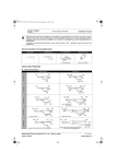
SEPARATION TUBE
3
INSTALLATION MANUAL
For authorized service personnel only.
(PART NO. 9371636139-02)
INSTALLATION PROCEDURE
1. The following table shows the sizes of the inlet and outlet pipes of the separation tubes.
KIT NAME : UTP-BX567A
Description
Liquid pipe
Discharge gas pipe
I.D ø15.88 (5/8)
• This manual describes the “Installation Specifications for Separation Tube Kits”. For the “outdoor unit”, refer to the Installation Instruction Sheet supplied with the
outdoor unit, and for the “indoor unit”, refer to the Installation Instruction Sheet supplied with the indoor unit.
• Please read this Installation Instruction Sheet thoroughly prior to installation, and perform the installation work in accordance with the instructions.
• Before performing the installation work, thoroughly read the “Safety Precautions” in the Installation Instruction Sheet supplied with the outdoor unit, and work ac-
Suction gas pipe
Reducer
I.D ø28.58 (1-1/8)
I.D ø22.22 (7/8)
I.D ø19.05 (3/4)
I.D ø12.7 (1/2)
I.D ø15.88 (5/8)
I.D ø19.05 (3/4)
Unit: mm (in.)
I.D ø12.7 (1/2)
I.D ø34.92 (1-3/8)
I.D ø28.58 (1-1/8)
I.D ø28.58 (1-1/8)
I.D ø34.92 (1-3/8)
I.D ø15.88 (5/8)
I.D ø41.27 (1-5/8)
I.D ø34.92 (1-3/8)
I.D ø41.27 (1-5/8)
cordingly.
• After installing the unit, perform a test run to make sure the unit operates normally. Then, explain to the customer how to operate and maintain the unit in accordance
with the Operating Manual (supplied with the indoor unit).
I.D ø22.22 (7/8)
I.D ø19.05 (3/4)
I.D ø15.88 (5/8)
I.D ø12.7 (1/2)
I.D ø9.52 (3/8)
• Hand this Installation Instruction Sheet, together with the Operating Manual, to the customer. Request the customer to keep them on hand.
1
PARTS LIST
I.D ø19.05 (3/4)
I.D ø12.7 (1/2)
I.D ø9.52 (3/8)
I.D ø6.35 (1/4)
I.D ø28.58 (1-1/8)
I.D ø28.58 (1-1/8)
I.D ø34.92 (1-3/8)
I.D ø28.58 (1-1/8)
I.D ø22.22 (7/8)
I.D ø19.05 (3/4)
I.D ø15.88 (5/8)
KIT NAME : UTP-BX567A
KIT NAME : UTP-BX180A
Description
Liquid pipe
Discharge gas pipe
Suction gas pipe
Reducer
Insulation
Tape
Description
Liquid pipe
1 pc.
Discharge gas pipe
1 pc.
1 pc.
1 pc.
1 pc.
Large 1 pc.
Medium: 1 pc.
Small 1 pc.
1 pc.
I.D ø12.7 (1/2)
I.D ø15.88 (5/8)
8 pcs.
KIT NAME : UTP-BX180A
I.D ø6.35 (1/4)
I.D ø9.52 (3/8)
I.D ø12.7 (1/2)
I.D ø15.88 (5/8)
Suction gas pipe
I.D ø9.52 (1/4)
I.D ø12.7 (1/2)
I.D ø15.88 (5/8)
I.D ø19.05 (3/4)
I.D ø22.22 (7/8)
I.D ø6.35 (1/4)
I.D ø9.52 (3/8)
1 pc.
Unit: mm (in.)
I.D ø22.22 (7/8)
I.D ø28.58 (1-1/8)
I.D ø28.58 (1-1/8)
I.D ø12.7 (1/2)
I.D ø15.88 (5/8)
I.D ø19.05 (3/4)
I.D ø22.22 (7/8)
I.D ø22.22 (7/8)
I.D ø22.22 (7/8)
Description
Liquid pipe
Discharge gas pipe
Suction gas pipe
I.D ø19.05 (3/4)
Reducer
Insulation
Tape
I.D ø12.7 (1/2)
I.D ø9.52 (3/8)
I.D ø6.35 (1/4)
1 pc.
1 pc.
1 pc.
Reducer
1 pc.
Large 1 pc.
Medium: 1 pc.
Small 1 pc.
8 pcs.
I.D ø15.88 (5/8)
I.D ø12.7 (1/2)
I.D ø19.05 (3/4)
I.D ø15.88 (5/8)
I.D ø12.7 (1/2)
I.D ø9.52 (3/8)
I.D ø9.52 (3/8)
KIT NAME : UTP-BX090A
Description
KIT NAME : UTP-BX090A
Liquid pipe
Unit: mm (in.)
Discharge gas pipe
Suction gas pipe
I.D ø9.52 (3/8)
I.D ø12.7 (1/2)
Description
Liquid pipe
Discharge gas pipe
Suction gas pipe
Reducer
Insulation
Tape
I.D ø6.35 (1/4)
I.D ø9.52 (3/8)
I.D ø12.7 (1/2)
I.D ø15.88 (5/8)
I.D ø6.35 (1/4)
1 pc.
1 pc.
1 pc.
2
1 pc.
Large 1 pc.
Medium: 1 pc.
Small 1 pc.
I.D ø9.52 (3/8)
8 pcs.
SELECTION PROCEDURE
I.D ø15.88 (5/8)
I.D ø15.88 (5/8)
I.D ø19.05 (3/4)
I.D ø19.05 (3/4)
I.D ø12.7 (1/2)
I.D ø22.22 (7/8)
I.D ø15.88 (5/8)
I.D ø19.05 (3/4)
I.D ø12.7 (1/2)
I.D ø15.88 (5/8)
I.D ø12.7 (1/2)
I.D ø19.05 (3/4)
I.D ø12.7 (1/2)
I.D ø22.22 (7/8)
I.D ø15.88 (5/8)
I.D ø12.7 (1/2)
I.D ø9.52 (3/8)
I.D ø6.35 (1/4)
Reducer
I.D ø19.05 (3/4)
I.D ø15.88 (5/8)
I.D ø12.7 (1/2)
I.D ø9.52 (3/8)
I.D ø6.35 (1/4)
I.D ø19.05 (3/4)
I.D ø15.88 (5/8)
I.D ø12.7 (1/2)
I.D ø9.52 (3/8)
For details on the selection of the separation tube kits, refer to the Installation Manual supplied with the outdoor unit or the DESIGN & TECHNICAL DATA.
2. Select the connections with the pipe diameters that match the selected pipe sizes from the separation
tubes, and cut them with a pipe cutter.
Joint pipe
CAUTION
If the field pipe is connected with angle
Outdoor unit1
(Master)
larger than specified, the balance of
Outdoor unit2
(Slave1)
Outdoor unit3
(Slave2)
split refrigerant flow will be lost, and the
refrigerant may concentrate upon specific
Compressor
malfunction
outdoor unit as shown in the following
Field pipe
figure. Such unbalanced refrigerant flow
may cause a compressor malfunction.
Co
Too much
refrigerant
Standard cutting position:
1/2L +3-0 mm ( +1/8-0 in. )
nne
Little
refrigerant
Little
refrigerant
ctio
ns
NOTE: Insert the field pipe firmly until it touches the joint pipe (Branch kit).
4. After brazing the pipes, use the supplied insulation to insulate them.
CAUTION
1) Remove the protective sheet from the double-stick tape that is affixed to the heat insulation.
Use a pipe cutter to cut a pipe. Point the pipe downward while deburring so that cutting chips will not enter inside the pipe.
3. Place the separation tubes horizontally or vertically so that the refrigerant separates evenly.
GOOD
GOOD
PROHIBITED
Double-stick tapes
Horizontal
2) Be sure to install the tape (accessory) in each heat insulation to the 2 positions as shown in the following figure.
Vertical
CAUTION
If it is placed horizontally, keep it within
± 15°. Otherwise, it will not separate the
refrigerant evenly, causing a reduction
in performance.
• During piping work, apply nitrogen
gas while brazing the pipes. If pipes
are brazed without applying nitrogen
gas, it will create a large amount of
oxidation film, which will cause a
critical malfunction.
• To prevent moisture or foreign matter
from entering during work, do not
leave the piping open.
• Refer to the Installation Manual
supplied with the outdoor unit for
airtightness test and evacuation
procedures.
PROHIBITED
Tapes (accessory)
PROHIBITED
GOOD: ±15°
GOOD: ±15°
3) Use tape (Field supply) to seal the seam so that there will be no gap at the junction between the aforementioned heat insulation and the heat insulation on the
local piping.
Tapes (Field supply)
Contact each other
PROHIBITED
PROHIBITED
Insulations (Field supply)
CAUTION
About the connecting curvature of field
The field pipe should be connected to the
branch kit so that the curved angle on
*0 to 26 mm
(0 to 1 in.)
each side is 3 degree or less.
CAUTION
*0 to 26 mm
(0 to 1 in.)
pipe and branch kit:
• Insulate the liquid and gas pipe completely. If not, it may cause the water condensation or performance reduction.
• Wrap the heat insulation with tape or pipe cover in order to extend the life time of heat insulation.
• Take proper measurement to strengthen by using another heat insulation at the following installing environment.
(a) Environment temperature ≥ 35°C (95°F) and humidity 85%.
(b) Environment temperature ≥ 25°C (77°F) and humidity 90%.
0.5 m (19-11/16 in.)
*: Allowed value based on “A” (center of field pipe) at 0.5 m (19-11/16 in.) from “B”
(junction of the branch kit).
9371636139-02_IM_EN.indd 1
Installation example
Heat insulation
(Field supply)
7/23/2013 3:53:11 PM