1
524X07801B
Issued 6/11/98
Warning: This service information is designed for experienced repair technicians only and is not designed for use by the general public. It does not contain
warnings or cautions to advise non-technical individuals of potential dangers in
attempting to service a product. Products powered by electricity should be serviced or repaired only by experienced professional technicians. Any attempt to
service or repair the product or products dealt with in this service information
by anyone else could result in serious injury or death.
FCC Warning
This equipment generates, uses, and can radiate radio frequency energy, and, if not installed
and used in accordance with the instruction manual, may cause interference to radio communications. This equipment has been tested and found to comply with the limits for a Class A
digital device pursuant to Part 15 of FCC Rules, which are designed to provide reasonable
protection against such interference when operated in a commercial environment. Operation
of this equipment in a residential area is likely to cause interference, in which case the user
at his own expense will be required to take necessary measures to correct the interference.
Battery Recycling Statement
The following statement applies if you purchased backup batteries with your system.
The product you have purchased contains rechargeable batteries. The batteries are recyclable. At the end of their useful life, under various state and local laws, it may be illegal to dispose of these batteries into the municipal waste stream. Check with your local solid waste
officials for details on recycling options or proper disposal.
The contents of this document are subject to change without notice and do not constitute a
commitment on the part of Panasonic Telecommunication Systems Company (PTSC). Every
effort has been made to ensure the accuracy of this document. However, due to ongoing product
improvements and revisions, Panasonic cannot guarantee the accuracy of printed material after
the date of publication nor can it accept responsibility for errors or omissions. Panasonic will
update and revise this document as needed.
The software and hardware described in this document may be used or copied only in accordance
with the terms of the license pertaining to said software or hardware.
Copyright 1998 by Panasonic Telecommunication Systems Company (PTSC)
All rights reserved.
Contents
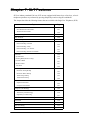
Chapter 1. About This Manual . . . . . . . . . . . . . . . . . . . . . . . . . . . . . 11
Chapter 2. List of Features . . . . . . . . . . . . . . . . . . . . . . . . . . . . . . . . 13
Chapter 3. System Features . . . . . . . . . . . . . . . . . . . . . . . . . . . . . . . 19
AEC Disconnect . . . . . . . . . . . . . . . . . . . . . . . . . . . . . . . . . . . . . . . . . . . . . . . . . . . . 22
Attendant Groups . . . . . . . . . . . . . . . . . . . . . . . . . . . . . . . . . . . . . . . . . . . . . . . . . . 22
Automatic Call Distributor . . . . . . . . . . . . . . . . . . . . . . . . . . . . . . . . . . . . . . . . . . . 23
Automatic Route Selection . . . . . . . . . . . . . . . . . . . . . . . . . . . . . . . . . . . . . . . . . . . 24
Automatic Trunk to Trunk Transfer . . . . . . . . . . . . . . . . . . . . . . . . . . . . . . . . . . . . 25
Background Music/MOH Separation . . . . . . . . . . . . . . . . . . . . . . . . . . . . . . . . . . . 25
Battery Backup. . . . . . . . . . . . . . . . . . . . . . . . . . . . . . . . . . . . . . . . . . . . . . . . . . . . . 25
Building Block Expansion Capability . . . . . . . . . . . . . . . . . . . . . . . . . . . . . . . . . . 26
Built-In Voice Processing Unit . . . . . . . . . . . . . . . . . . . . . . . . . . . . . . . . . . . . . . . . 26
Call Progress Tones . . . . . . . . . . . . . . . . . . . . . . . . . . . . . . . . . . . . . . . . . . . . . . . . 27
Caller ID . . . . . . . . . . . . . . . . . . . . . . . . . . . . . . . . . . . . . . . . . . . . . . . . . . . . . . . . . . 28
Centrex/PBX Compatibility . . . . . . . . . . . . . . . . . . . . . . . . . . . . . . . . . . . . . . . . . . . 28
Class of Service . . . . . . . . . . . . . . . . . . . . . . . . . . . . . . . . . . . . . . . . . . . . . . . . . . . . 29
Class
Class
Class
Class
of Service - Trunk/Tie. . . . . . . . . . . . . . . . . . . . . . . . . . . . . . . . . . . . . . . . . . . . . . .
of Service - Ext/Ext Restriction . . . . . . . . . . . . . . . . . . . . . . . . . . . . . . . . . . . . . . .
of Service - Extension Feature. . . . . . . . . . . . . . . . . . . . . . . . . . . . . . . . . . . . . . . .
of Service - Trunk to Trunk Restriction . . . . . . . . . . . . . . . . . . . . . . . . . . . . . . . . .
29
30
30
32
CO Ringing Types . . . . . . . . . . . . . . . . . . . . . . . . . . . . . . . . . . . . . . . . . . . . . . . . . . 32
Direct Inward Dial Ringing . . . . . . . . . . . . . . . . . . . . . . . . . . . . . . . . . . . . . . . . . . . . . . . .
Direct In Line Ringing. . . . . . . . . . . . . . . . . . . . . . . . . . . . . . . . . . . . . . . . . . . . . . . . . . . .
Direct Inward System Access Ringing . . . . . . . . . . . . . . . . . . . . . . . . . . . . . . . . . . . . . . .
Multiple Ringing . . . . . . . . . . . . . . . . . . . . . . . . . . . . . . . . . . . . . . . . . . . . . . . . . . . . . . . .
32
33
33
34
CO Trunk Interface. . . . . . . . . . . . . . . . . . . . . . . . . . . . . . . . . . . . . . . . . . . . . . . . . . 34
CO Trunk Interface - DID . . . . . . . . . . . . . . . . . . . . . . . . . . . . . . . . . . . . . . . . . . . . . . . . .
CO Trunk Interface - Ground Start. . . . . . . . . . . . . . . . . . . . . . . . . . . . . . . . . . . . . . . . . .
CO Trunk Interface - ISDN BRI . . . . . . . . . . . . . . . . . . . . . . . . . . . . . . . . . . . . . . . . . . . .
CO Trunk Interface - ISDN-PRI . . . . . . . . . . . . . . . . . . . . . . . . . . . . . . . . . . . . . . . . . . . .
CO Trunk Interface - Loop Start. . . . . . . . . . . . . . . . . . . . . . . . . . . . . . . . . . . . . . . . . . . .
34
35
35
35
36
Computer Telephony Integration Capability . . . . . . . . . . . . . . . . . . . . . . . . . . . . . 36
Data Security . . . . . . . . . . . . . . . . . . . . . . . . . . . . . . . . . . . . . . . . . . . . . . . . . . . . . . 37
Day/Night System Mode . . . . . . . . . . . . . . . . . . . . . . . . . . . . . . . . . . . . . . . . . . . . . 37
Manual Day/Night Mode . . . . . . . . . . . . . . . . . . . . . . . . . . . . . . . . . . . . . . . . . . . . . . . . . 38
Automatic Day/Night Mode . . . . . . . . . . . . . . . . . . . . . . . . . . . . . . . . . . . . . . . . . . . . . . . 39
Digital Pad . . . . . . . . . . . . . . . . . . . . . . . . . . . . . . . . . . . . . . . . . . . . . . . . . . . . . . . . 40
Direct Inward System Access. . . . . . . . . . . . . . . . . . . . . . . . . . . . . . . . . . . . . . . . . 40
576-13-700
DBS 576 (USA), Revised 6/11/98
3
Contents
Section 700 - Operation
Distinctive Ringing . . . . . . . . . . . . . . . . . . . . . . . . . . . . . . . . . . . . . . . . . . . . . . . . . 41
Door Box. . . . . . . . . . . . . . . . . . . . . . . . . . . . . . . . . . . . . . . . . . . . . . . . . . . . . . . . . . 42
Door Box Sensor . . . . . . . . . . . . . . . . . . . . . . . . . . . . . . . . . . . . . . . . . . . . . . . . . . . . . . . 43
Extension Interface . . . . . . . . . . . . . . . . . . . . . . . . . . . . . . . . . . . . . . . . . . . . . . . . . 43
Digital Key Telephones . . . . . . . . . . . . . . . . . . . . . . . . . . . . . . . . . . . . . . . . . . . . . . . . . .
Analog Device Capability . . . . . . . . . . . . . . . . . . . . . . . . . . . . . . . . . . . . . . . . . . . . . . . . .
DP/DTMF Single Line Telephones (SLTs). . . . . . . . . . . . . . . . . . . . . . . . . . . . . . . . . . . .
ISDN/BRI S-Point Interface . . . . . . . . . . . . . . . . . . . . . . . . . . . . . . . . . . . . . . . . . . . . . . .
ISDN/PRI S-Point Interface . . . . . . . . . . . . . . . . . . . . . . . . . . . . . . . . . . . . . . . . . . . . . . .
43
44
44
44
45
Flexible Numbering Plan . . . . . . . . . . . . . . . . . . . . . . . . . . . . . . . . . . . . . . . . . . . . . 45
Free Slot . . . . . . . . . . . . . . . . . . . . . . . . . . . . . . . . . . . . . . . . . . . . . . . . . . . . . . . . . . 46
Hunting Groups . . . . . . . . . . . . . . . . . . . . . . . . . . . . . . . . . . . . . . . . . . . . . . . . . . . . 46
Pilot Terminal Hunt Group . . . . . . . . . . . . . . . . . . . . . . . . . . . . . . . . . . . . . . . . . . . . . . . .
Pilot Distributed Hunt Group . . . . . . . . . . . . . . . . . . . . . . . . . . . . . . . . . . . . . . . . . . . . . .
Switch Back Hunt Group . . . . . . . . . . . . . . . . . . . . . . . . . . . . . . . . . . . . . . . . . . . . . . . . .
Circular Hunt Group . . . . . . . . . . . . . . . . . . . . . . . . . . . . . . . . . . . . . . . . . . . . . . . . . . . . .
Next Extension/Hunt Group . . . . . . . . . . . . . . . . . . . . . . . . . . . . . . . . . . . . . . . . . . . . . . .
46
47
47
47
47
Internal Hold Tone . . . . . . . . . . . . . . . . . . . . . . . . . . . . . . . . . . . . . . . . . . . . . . . . . .
MCO Tenant Group . . . . . . . . . . . . . . . . . . . . . . . . . . . . . . . . . . . . . . . . . . . . . . . . .
Memory Backup . . . . . . . . . . . . . . . . . . . . . . . . . . . . . . . . . . . . . . . . . . . . . . . . . . . .
Music-on-Hold . . . . . . . . . . . . . . . . . . . . . . . . . . . . . . . . . . . . . . . . . . . . . . . . . . . . .
Name Assignments . . . . . . . . . . . . . . . . . . . . . . . . . . . . . . . . . . . . . . . . . . . . . . . . .
48
48
49
50
50
Extension Name Assignments . . . . . . . . . . . . . . . . . . . . . . . . . . . . . . . . . . . . . . . . . . . . . 51
Speed Dial Name Assignments . . . . . . . . . . . . . . . . . . . . . . . . . . . . . . . . . . . . . . . . . . . . 54
Network Facilities . . . . . . . . . . . . . . . . . . . . . . . . . . . . . . . . . . . . . . . . . . . . . . . . . . 56
Network Call Transfer . . . . . . . . . . . . . . . . . . . . . . . . . . . . . . . . . . . . . . . . . . . . . . . . . . .
Network Extension Calling . . . . . . . . . . . . . . . . . . . . . . . . . . . . . . . . . . . . . . . . . . . . . . . .
Network Paging . . . . . . . . . . . . . . . . . . . . . . . . . . . . . . . . . . . . . . . . . . . . . . . . . . . . . . . .
Network Call Routing . . . . . . . . . . . . . . . . . . . . . . . . . . . . . . . . . . . . . . . . . . . . . . . . . . . .
Tandem Connection. . . . . . . . . . . . . . . . . . . . . . . . . . . . . . . . . . . . . . . . . . . . . . . . . . . . .
57
57
57
57
57
Non-Blocking Architecture . . . . . . . . . . . . . . . . . . . . . . . . . . . . . . . . . . . . . . . . . . .
Power Failure Transfer . . . . . . . . . . . . . . . . . . . . . . . . . . . . . . . . . . . . . . . . . . . . . .
Power On Maintenance . . . . . . . . . . . . . . . . . . . . . . . . . . . . . . . . . . . . . . . . . . . . . .
Programming Devices . . . . . . . . . . . . . . . . . . . . . . . . . . . . . . . . . . . . . . . . . . . . . . .
57
58
58
59
Telephone Programming . . . . . . . . . . . . . . . . . . . . . . . . . . . . . . . . . . . . . . . . . . . . . . . . . 59
PC-Based Customizing Tool . . . . . . . . . . . . . . . . . . . . . . . . . . . . . . . . . . . . . . . . . . . . . . 59
Ringing Modes . . . . . . . . . . . . . . . . . . . . . . . . . . . . . . . . . . . . . . . . . . . . . . . . . . . . . 59
Day 1/ Day 2/Night Ringing . . . . . . . . . . . . . . . . . . . . . . . . . . . . . . . . . . . . . . . . . . . . . . .
Day 1/ Day 2/Night Delayed Ringing . . . . . . . . . . . . . . . . . . . . . . . . . . . . . . . . . . . . . . . .
DID Day/Night Ringing . . . . . . . . . . . . . . . . . . . . . . . . . . . . . . . . . . . . . . . . . . . . . . . . . . .
DID Day/Night Busy/Delayed Ringing . . . . . . . . . . . . . . . . . . . . . . . . . . . . . . . . . . . . . . .
Busy Lamp Field Ringing . . . . . . . . . . . . . . . . . . . . . . . . . . . . . . . . . . . . . . . . . . . . . . . . .
Busy Lamp Field Delayed Ringing . . . . . . . . . . . . . . . . . . . . . . . . . . . . . . . . . . . . . . . . . .
Slide Ringing . . . . . . . . . . . . . . . . . . . . . . . . . . . . . . . . . . . . . . . . . . . . . . . . . . . . . . . . . .
Alarm Ringing . . . . . . . . . . . . . . . . . . . . . . . . . . . . . . . . . . . . . . . . . . . . . . . . . . . . . . . . .
60
60
61
61
61
62
62
62
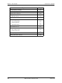
SSD TRS Override . . . . . . . . . . . . . . . . . . . . . . . . . . . . . . . . . . . . . . . . . . . . . . . . . . 63
Station Message Detail Recording . . . . . . . . . . . . . . . . . . . . . . . . . . . . . . . . . . . . . 63
Toll Restriction Service . . . . . . . . . . . . . . . . . . . . . . . . . . . . . . . . . . . . . . . . . . . . . . 65
4
DBS 576 (USA), Revised 6/11/98
576-13-700
Section 700 - Operation
Contents
Trunk Access Groups . . . . . . . . . . . . . . . . . . . . . . . . . . . . . . . . . . . . . . . . . . . . . . . 66
Virtual Port . . . . . . . . . . . . . . . . . . . . . . . . . . . . . . . . . . . . . . . . . . . . . . . . . . . . . . . . 67
Virtual Port used for Virtual Extension . . . . . . . . . . . . . . . . . . . . . . . . . . . . . . . . . . . . . . . 67
Virtual Port used for Floating Hold . . . . . . . . . . . . . . . . . . . . . . . . . . . . . . . . . . . . . . . . . . 67
Voice Mail Integration (Third Party) . . . . . . . . . . . . . . . . . . . . . . . . . . . . . . . . . . . . 68
Answer Supervision for Voice Mail . . . . . . . . . . . . . . . . . . . . . . . . . . . . . . . . . . . . . . . . .
Call Forward ID Code for Voice Mail . . . . . . . . . . . . . . . . . . . . . . . . . . . . . . . . . . . . . . . .
DID/DNIS/DDI Voice Mail ID Code . . . . . . . . . . . . . . . . . . . . . . . . . . . . . . . . . . . . . . . . .
High Priority Message Waiting . . . . . . . . . . . . . . . . . . . . . . . . . . . . . . . . . . . . . . . . . . . . .
Message Key ID Code . . . . . . . . . . . . . . . . . . . . . . . . . . . . . . . . . . . . . . . . . . . . . . . . . . .
Voice Mail Transfer Key. . . . . . . . . . . . . . . . . . . . . . . . . . . . . . . . . . . . . . . . . . . . . . . . . .
68
68
69
70
70
71
Chapter 4. User Maintenance . . . . . . . . . . . . . . . . . . . . . . . . . . . . . . 73
Introduction . . . . . . . . . . . . . . . . . . . . . . . . . . . . . . . . . . . . . . . . . . . . . . . . . . . . . . . 74
About User Programming . . . . . . . . . . . . . . . . . . . . . . . . . . . . . . . . . . . . . . . . . . . . 74
Set System Date/Time/Day . . . . . . . . . . . . . . . . . . . . . . . . . . . . . . . . . . . . . . . . . . . 75
Set Personal Speed Dial Numbers . . . . . . . . . . . . . . . . . . . . . . . . . . . . . . . . . . . . . 76
Set Personal Speed Dial Names . . . . . . . . . . . . . . . . . . . . . . . . . . . . . . . . . . . . . . . 77
Set System Speed Dial Numbers . . . . . . . . . . . . . . . . . . . . . . . . . . . . . . . . . . . . . . 82
Set System Speed Dial Names . . . . . . . . . . . . . . . . . . . . . . . . . . . . . . . . . . . . . . . . 83
Set System Speed Dial Index . . . . . . . . . . . . . . . . . . . . . . . . . . . . . . . . . . . . . . . . . 84
Set Extension Names . . . . . . . . . . . . . . . . . . . . . . . . . . . . . . . . . . . . . . . . . . . . . . . 86
Set Verified Account Codes . . . . . . . . . . . . . . . . . . . . . . . . . . . . . . . . . . . . . . . . . . 87
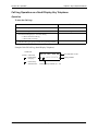
Set Call-Forward ID Codes for Voice Mail . . . . . . . . . . . . . . . . . . . . . . . . . . . . . . . 89
Set Message Key ID Code . . . . . . . . . . . . . . . . . . . . . . . . . . . . . . . . . . . . . . . . . . . . 90
Set Mode Schedule . . . . . . . . . . . . . . . . . . . . . . . . . . . . . . . . . . . . . . . . . . . . . . . . . 91
Set Special Day Mode . . . . . . . . . . . . . . . . . . . . . . . . . . . . . . . . . . . . . . . . . . . . . . . 93
Set Exception Day Mode . . . . . . . . . . . . . . . . . . . . . . . . . . . . . . . . . . . . . . . . . . . . . 99
Set Day of Week Mode. . . . . . . . . . . . . . . . . . . . . . . . . . . . . . . . . . . . . . . . . . . . . . 101
Set Walking TRS Codes . . . . . . . . . . . . . . . . . . . . . . . . . . . . . . . . . . . . . . . . . . . . 103
Set Call Forward Busy Destination Extension . . . . . . . . . . . . . . . . . . . . . . . . . . 104
Set Call Forward No Answer Destination Extension . . . . . . . . . . . . . . . . . . . . . 105
Set Caller ID Logging Extensions . . . . . . . . . . . . . . . . . . . . . . . . . . . . . . . . . . . . 106
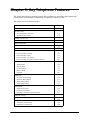
Chapter 5. Key Telephone Features. . . . . . . . . . . . . . . . . . . . . . . . 109
Key Telephone . . . . . . . . . . . . . . . . . . . . . . . . . . . . . . . . . . . . . . . . . . . . . . . . . . . . 112
Account Codes. . . . . . . . . . . . . . . . . . . . . . . . . . . . . . . . . . . . . . . . . . . . . . . . . . . . 112
Non-Verified Account Codes . . . . . . . . . . . . . . . . . . . . . . . . . . . . . . . . . . . . . . . . . . . . . 113
Verified Account Codes . . . . . . . . . . . . . . . . . . . . . . . . . . . . . . . . . . . . . . . . . . . . . . . . . 114
Attendant Group Calls. . . . . . . . . . . . . . . . . . . . . . . . . . . . . . . . . . . . . . . . . . . . . .
Auto Repeat Dial . . . . . . . . . . . . . . . . . . . . . . . . . . . . . . . . . . . . . . . . . . . . . . . . . .
Background Music. . . . . . . . . . . . . . . . . . . . . . . . . . . . . . . . . . . . . . . . . . . . . . . . .
Busy Override . . . . . . . . . . . . . . . . . . . . . . . . . . . . . . . . . . . . . . . . . . . . . . . . . . . .
Callback Request . . . . . . . . . . . . . . . . . . . . . . . . . . . . . . . . . . . . . . . . . . . . . . . . . .
576-13-700
DBS 576 (USA), Revised 6/11/98
115
116
116
117
119
5
Contents
Section 700 - Operation
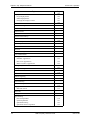
Call Forwarding . . . . . . . . . . . . . . . . . . . . . . . . . . . . . . . . . . . . . . . . . . . . . . . . . . . 120
Call Forwarding-All Calls . . . . . . . . . . . . . . . . . . . . . . . . . . . . . . . . . . . . . . . . . . . . . . . .
Call Forwarding - Busy. . . . . . . . . . . . . . . . . . . . . . . . . . . . . . . . . . . . . . . . . . . . . . . . . .
Call Forwarding - No Answer . . . . . . . . . . . . . . . . . . . . . . . . . . . . . . . . . . . . . . . . . . . . .
Call Forwarding and Do-Not-Disturb . . . . . . . . . . . . . . . . . . . . . . . . . . . . . . . . . . . . . . .
120
121
122
123
Call Hold . . . . . . . . . . . . . . . . . . . . . . . . . . . . . . . . . . . . . . . . . . . . . . . . . . . . . . . . . 124
System Hold. . . . . . . . . . . . . . . . . . . . . . . . . . . . . . . . . . . . . . . . . . . . . . . . . . . . . . . . . .
Floating Hold . . . . . . . . . . . . . . . . . . . . . . . . . . . . . . . . . . . . . . . . . . . . . . . . . . . . . . . . .
Exclusive Hold . . . . . . . . . . . . . . . . . . . . . . . . . . . . . . . . . . . . . . . . . . . . . . . . . . . . . . . .
Broker’s Hold . . . . . . . . . . . . . . . . . . . . . . . . . . . . . . . . . . . . . . . . . . . . . . . . . . . . . . . . .
Call Park . . . . . . . . . . . . . . . . . . . . . . . . . . . . . . . . . . . . . . . . . . . . . . . . . . . . . . . . . . . .
124
125
126
127
127
Call Pickup . . . . . . . . . . . . . . . . . . . . . . . . . . . . . . . . . . . . . . . . . . . . . . . . . . . . . . . 129
Extension Group Pickup . . . . . . . . . . . . . . . . . . . . . . . . . . . . . . . . . . . . . . . . . . . . . . . .
Extension Direct Pickup . . . . . . . . . . . . . . . . . . . . . . . . . . . . . . . . . . . . . . . . . . . . . . . . .
Trunk Group Pickup . . . . . . . . . . . . . . . . . . . . . . . . . . . . . . . . . . . . . . . . . . . . . . . . . . . .
Trunk Direct Pickup . . . . . . . . . . . . . . . . . . . . . . . . . . . . . . . . . . . . . . . . . . . . . . . . . . . .
129
131
131
132
Call Transfer . . . . . . . . . . . . . . . . . . . . . . . . . . . . . . . . . . . . . . . . . . . . . . . . . . . . . . 132
Supervised Transfer. . . . . . . . . . . . . . . . . . . . . . . . . . . . . . . . . . . . . . . . . . . . . . . . . . . . 132
Unsupervised Transfer. . . . . . . . . . . . . . . . . . . . . . . . . . . . . . . . . . . . . . . . . . . . . . . . . . 134
Camping a Call Onto a Busy Extension . . . . . . . . . . . . . . . . . . . . . . . . . . . . . . . . . . . . . 135
Caller ID Call Log . . . . . . . . . . . . . . . . . . . . . . . . . . . . . . . . . . . . . . . . . . . . . . . . . . 136
Call Log Operation on a Small Display Key Telephone . . . . . . . . . . . . . . . . . . . . . . . . . 137
Call Log Operation on a Large Display Key Telephone . . . . . . . . . . . . . . . . . . . . . . . . . 139
Camp-on (Call Waiting) . . . . . . . . . . . . . . . . . . . . . . . . . . . . . . . . . . . . . . . . . . . . . 141
Conference Calls . . . . . . . . . . . . . . . . . . . . . . . . . . . . . . . . . . . . . . . . . . . . . . . . . . 143
Three-Party Conferencing . . . . . . . . . . . . . . . . . . . . . . . . . . . . . . . . . . . . . . . . . . . . . . . 143
Eight-Party Conferencing . . . . . . . . . . . . . . . . . . . . . . . . . . . . . . . . . . . . . . . . . . . . . . . . 144
Display Information . . . . . . . . . . . . . . . . . . . . . . . . . . . . . . . . . . . . . . . . . . . . . . . . 145
Large Display Phone . . . . . . . . . . . . . . . . . . . . . . . . . . . . . . . . . . . . . . . . . . . . . . . . . . . 146
Small Display Phone . . . . . . . . . . . . . . . . . . . . . . . . . . . . . . . . . . . . . . . . . . . . . . . . . . . 147
Changing the Display Contrast . . . . . . . . . . . . . . . . . . . . . . . . . . . . . . . . . . . . . . . . . . . 147
Do-Not-Disturb . . . . . . . . . . . . . . . . . . . . . . . . . . . . . . . . . . . . . . . . . . . . . . . . . . . .
DP to DTMF Signal Conversion . . . . . . . . . . . . . . . . . . . . . . . . . . . . . . . . . . . . . .
DSS/72 Console . . . . . . . . . . . . . . . . . . . . . . . . . . . . . . . . . . . . . . . . . . . . . . . . . . .
EM/24 Console . . . . . . . . . . . . . . . . . . . . . . . . . . . . . . . . . . . . . . . . . . . . . . . . . . . .
Flash . . . . . . . . . . . . . . . . . . . . . . . . . . . . . . . . . . . . . . . . . . . . . . . . . . . . . . . . . . . .
Flexible Function Keys . . . . . . . . . . . . . . . . . . . . . . . . . . . . . . . . . . . . . . . . . . . . .
Handsfree Answerback . . . . . . . . . . . . . . . . . . . . . . . . . . . . . . . . . . . . . . . . . . . . .
Handsfree Operation . . . . . . . . . . . . . . . . . . . . . . . . . . . . . . . . . . . . . . . . . . . . . . .
Headset Operation . . . . . . . . . . . . . . . . . . . . . . . . . . . . . . . . . . . . . . . . . . . . . . . . .
Hot Dial Pad . . . . . . . . . . . . . . . . . . . . . . . . . . . . . . . . . . . . . . . . . . . . . . . . . . . . . .
148
150
150
151
151
152
158
158
159
160
Considerations . . . . . . . . . . . . . . . . . . . . . . . . . . . . . . . . . . . . . . . . . . . . . . . . . . . . . . . . 160
Hot Line. . . . . . . . . . . . . . . . . . . . . . . . . . . . . . . . . . . . . . . . . . . . . . . . . . . . . . . . . .
Intercom Calling. . . . . . . . . . . . . . . . . . . . . . . . . . . . . . . . . . . . . . . . . . . . . . . . . . .
Last Number Redial . . . . . . . . . . . . . . . . . . . . . . . . . . . . . . . . . . . . . . . . . . . . . . . .
Line Appearances . . . . . . . . . . . . . . . . . . . . . . . . . . . . . . . . . . . . . . . . . . . . . . . . .
160
161
162
163
DSS/BLF Appearances . . . . . . . . . . . . . . . . . . . . . . . . . . . . . . . . . . . . . . . . . . . . . . . . . 163
Direct Line Appearances . . . . . . . . . . . . . . . . . . . . . . . . . . . . . . . . . . . . . . . . . . . . . . . . 165
6
DBS 576 (USA), Revised 6/11/98
576-13-700
Section 700 - Operation
Contents
Multi-CO (MCO) Appearances . . . . . . . . . . . . . . . . . . . . . . . . . . . . . . . . . . . . . . . . . . . . 165
Message Key . . . . . . . . . . . . . . . . . . . . . . . . . . . . . . . . . . . . . . . . . . . . . . . . . . . . .
Message Waiting / Callback . . . . . . . . . . . . . . . . . . . . . . . . . . . . . . . . . . . . . . . . .
Mute Function . . . . . . . . . . . . . . . . . . . . . . . . . . . . . . . . . . . . . . . . . . . . . . . . . . . .
Offhook Monitor . . . . . . . . . . . . . . . . . . . . . . . . . . . . . . . . . . . . . . . . . . . . . . . . . . .
Offhook Signaling . . . . . . . . . . . . . . . . . . . . . . . . . . . . . . . . . . . . . . . . . . . . . . . . .
Offhook Voice Announce . . . . . . . . . . . . . . . . . . . . . . . . . . . . . . . . . . . . . . . . . . .
One-Touch Keys . . . . . . . . . . . . . . . . . . . . . . . . . . . . . . . . . . . . . . . . . . . . . . . . . .
Onhook Dialing . . . . . . . . . . . . . . . . . . . . . . . . . . . . . . . . . . . . . . . . . . . . . . . . . . .
Paging . . . . . . . . . . . . . . . . . . . . . . . . . . . . . . . . . . . . . . . . . . . . . . . . . . . . . . . . . . .
166
167
169
170
170
171
173
175
176
Meet-Me Answer . . . . . . . . . . . . . . . . . . . . . . . . . . . . . . . . . . . . . . . . . . . . . . . . . . . . . . 177
Reset Call . . . . . . . . . . . . . . . . . . . . . . . . . . . . . . . . . . . . . . . . . . . . . . . . . . . . . . . . 177
Ringing Line Preference . . . . . . . . . . . . . . . . . . . . . . . . . . . . . . . . . . . . . . . . . . . . 178
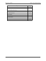
Speed Dialing . . . . . . . . . . . . . . . . . . . . . . . . . . . . . . . . . . . . . . . . . . . . . . . . . . . . . 179
Personal Speed Dial . . . . . . . . . . . . . . . . . . . . . . . . . . . . . . . . . . . . . . . . . . . . . . . . . . .
System Speed Dial . . . . . . . . . . . . . . . . . . . . . . . . . . . . . . . . . . . . . . . . . . . . . . . . . . . .
Speed Dial Linking . . . . . . . . . . . . . . . . . . . . . . . . . . . . . . . . . . . . . . . . . . . . . . . . . . . . .
Speed Dial Name Assignments . . . . . . . . . . . . . . . . . . . . . . . . . . . . . . . . . . . . . . . . . . .
179
181
183
185
Timed Reminder Call . . . . . . . . . . . . . . . . . . . . . . . . . . . . . . . . . . . . . . . . . . . . . . . 189
Trunk Access . . . . . . . . . . . . . . . . . . . . . . . . . . . . . . . . . . . . . . . . . . . . . . . . . . . . . 190
CO Line Key Trunk Access . . . . . . . . . . . . . . . . . . . . . . . . . . . . . . . . . . . . . . . . . . . . . .
Direct Trunk Access . . . . . . . . . . . . . . . . . . . . . . . . . . . . . . . . . . . . . . . . . . . . . . . . . . . .
MCO Line Preference . . . . . . . . . . . . . . . . . . . . . . . . . . . . . . . . . . . . . . . . . . . . . . . . . .
MCO Trunk Access . . . . . . . . . . . . . . . . . . . . . . . . . . . . . . . . . . . . . . . . . . . . . . . . . . . .
191
191
192
192
Trunk Queuing . . . . . . . . . . . . . . . . . . . . . . . . . . . . . . . . . . . . . . . . . . . . . . . . . . . .
Variable Mode. . . . . . . . . . . . . . . . . . . . . . . . . . . . . . . . . . . . . . . . . . . . . . . . . . . . .
Voice Recognition . . . . . . . . . . . . . . . . . . . . . . . . . . . . . . . . . . . . . . . . . . . . . . . . .
Volume Control . . . . . . . . . . . . . . . . . . . . . . . . . . . . . . . . . . . . . . . . . . . . . . . . . . .
Walking TRS Class of Service . . . . . . . . . . . . . . . . . . . . . . . . . . . . . . . . . . . . . . .
194
195
197
197
198
Chapter 6. DSLT Features . . . . . . . . . . . . . . . . . . . . . . . . . . . . . . . . 201
Digital Single Line Telephone. . . . . . . . . . . . . . . . . . . . . . . . . . . . . . . . . . . . . . . . 203
Account Codes. . . . . . . . . . . . . . . . . . . . . . . . . . . . . . . . . . . . . . . . . . . . . . . . . . . . 203
Non-Verified Account Codes . . . . . . . . . . . . . . . . . . . . . . . . . . . . . . . . . . . . . . . . . . . . . 204
Verified Account Codes . . . . . . . . . . . . . . . . . . . . . . . . . . . . . . . . . . . . . . . . . . . . . . . . . 205
Attendant Group Calls. . . . . . . . . . . . . . . . . . . . . . . . . . . . . . . . . . . . . . . . . . . . . .
Auto Repeat Dial . . . . . . . . . . . . . . . . . . . . . . . . . . . . . . . . . . . . . . . . . . . . . . . . . .
Background Music. . . . . . . . . . . . . . . . . . . . . . . . . . . . . . . . . . . . . . . . . . . . . . . . .
Busy Override . . . . . . . . . . . . . . . . . . . . . . . . . . . . . . . . . . . . . . . . . . . . . . . . . . . .
Callback Request . . . . . . . . . . . . . . . . . . . . . . . . . . . . . . . . . . . . . . . . . . . . . . . . . .
Call Forwarding . . . . . . . . . . . . . . . . . . . . . . . . . . . . . . . . . . . . . . . . . . . . . . . . . . .
206
207
207
208
209
210
Call Forwarding-All Calls . . . . . . . . . . . . . . . . . . . . . . . . . . . . . . . . . . . . . . . . . . . . . . . .
Call Forwarding - Busy. . . . . . . . . . . . . . . . . . . . . . . . . . . . . . . . . . . . . . . . . . . . . . . . . .
Call Forwarding - No Answer . . . . . . . . . . . . . . . . . . . . . . . . . . . . . . . . . . . . . . . . . . . . .
Call Forwarding and Do-Not-Disturb . . . . . . . . . . . . . . . . . . . . . . . . . . . . . . . . . . . . . . .
210
211
212
213
Call Hold . . . . . . . . . . . . . . . . . . . . . . . . . . . . . . . . . . . . . . . . . . . . . . . . . . . . . . . . . 214
576-13-700
DBS 576 (USA), Revised 6/11/98
7
Contents
Section 700 - Operation
System Hold. . . . . . . . . . . . . . . . . . . . . . . . . . . . . . . . . . . . . . . . . . . . . . . . . . . . . . . . . .
Floating Hold . . . . . . . . . . . . . . . . . . . . . . . . . . . . . . . . . . . . . . . . . . . . . . . . . . . . . . . . .
Exclusive Hold . . . . . . . . . . . . . . . . . . . . . . . . . . . . . . . . . . . . . . . . . . . . . . . . . . . . . . . .
Broker’s Hold . . . . . . . . . . . . . . . . . . . . . . . . . . . . . . . . . . . . . . . . . . . . . . . . . . . . . . . . .
Call Park . . . . . . . . . . . . . . . . . . . . . . . . . . . . . . . . . . . . . . . . . . . . . . . . . . . . . . . . . . . .
214
215
216
217
217
Call Pickup . . . . . . . . . . . . . . . . . . . . . . . . . . . . . . . . . . . . . . . . . . . . . . . . . . . . . . . 219
Extension Group Pickup . . . . . . . . . . . . . . . . . . . . . . . . . . . . . . . . . . . . . . . . . . . . . . . .
Extension Direct Pickup . . . . . . . . . . . . . . . . . . . . . . . . . . . . . . . . . . . . . . . . . . . . . . . . .
Trunk Group Pickup . . . . . . . . . . . . . . . . . . . . . . . . . . . . . . . . . . . . . . . . . . . . . . . . . . . .
Trunk Direct Pickup . . . . . . . . . . . . . . . . . . . . . . . . . . . . . . . . . . . . . . . . . . . . . . . . . . . .
219
220
221
221
Call Transfer . . . . . . . . . . . . . . . . . . . . . . . . . . . . . . . . . . . . . . . . . . . . . . . . . . . . . . 222
Supervised Transfer. . . . . . . . . . . . . . . . . . . . . . . . . . . . . . . . . . . . . . . . . . . . . . . . . . . . 222
Unsupervised Transfer. . . . . . . . . . . . . . . . . . . . . . . . . . . . . . . . . . . . . . . . . . . . . . . . . . 223
Camping a Call Onto a Busy Extension . . . . . . . . . . . . . . . . . . . . . . . . . . . . . . . . . . . . . 223
Camp-On (Call Waiting). . . . . . . . . . . . . . . . . . . . . . . . . . . . . . . . . . . . . . . . . . . . . 224
Conference Calls . . . . . . . . . . . . . . . . . . . . . . . . . . . . . . . . . . . . . . . . . . . . . . . . . . 226
Three-Party Conferencing . . . . . . . . . . . . . . . . . . . . . . . . . . . . . . . . . . . . . . . . . . . . . . . 226
Eight-Party Conferencing . . . . . . . . . . . . . . . . . . . . . . . . . . . . . . . . . . . . . . . . . . . . . . . . 226
Do-Not-Disturb . . . . . . . . . . . . . . . . . . . . . . . . . . . . . . . . . . . . . . . . . . . . . . . . . . . .
DP to DTMF Signal Conversion . . . . . . . . . . . . . . . . . . . . . . . . . . . . . . . . . . . . . .
Flash . . . . . . . . . . . . . . . . . . . . . . . . . . . . . . . . . . . . . . . . . . . . . . . . . . . . . . . . . . . .
Hot Line. . . . . . . . . . . . . . . . . . . . . . . . . . . . . . . . . . . . . . . . . . . . . . . . . . . . . . . . . .
Intercom Calling. . . . . . . . . . . . . . . . . . . . . . . . . . . . . . . . . . . . . . . . . . . . . . . . . . .
Last Number Redial . . . . . . . . . . . . . . . . . . . . . . . . . . . . . . . . . . . . . . . . . . . . . . . .
Message Waiting / Callback . . . . . . . . . . . . . . . . . . . . . . . . . . . . . . . . . . . . . . . . .
Onhook Dialing . . . . . . . . . . . . . . . . . . . . . . . . . . . . . . . . . . . . . . . . . . . . . . . . . . .
Offhook Signaling . . . . . . . . . . . . . . . . . . . . . . . . . . . . . . . . . . . . . . . . . . . . . . . . .
Offhook Voice Announce . . . . . . . . . . . . . . . . . . . . . . . . . . . . . . . . . . . . . . . . . . .
Paging . . . . . . . . . . . . . . . . . . . . . . . . . . . . . . . . . . . . . . . . . . . . . . . . . . . . . . . . . . .
228
229
230
230
231
232
232
234
234
235
236
Meet-Me Answer . . . . . . . . . . . . . . . . . . . . . . . . . . . . . . . . . . . . . . . . . . . . . . . . . . . . . . 237
Reset Call . . . . . . . . . . . . . . . . . . . . . . . . . . . . . . . . . . . . . . . . . . . . . . . . . . . . . . . . 237
Speed Dialing . . . . . . . . . . . . . . . . . . . . . . . . . . . . . . . . . . . . . . . . . . . . . . . . . . . . . 238
Personal Speed Dial . . . . . . . . . . . . . . . . . . . . . . . . . . . . . . . . . . . . . . . . . . . . . . . . . . . 238
System Speed Dial . . . . . . . . . . . . . . . . . . . . . . . . . . . . . . . . . . . . . . . . . . . . . . . . . . . . 240
Speed Dial Linking . . . . . . . . . . . . . . . . . . . . . . . . . . . . . . . . . . . . . . . . . . . . . . . . . . . . . 241
Timed Reminder Call . . . . . . . . . . . . . . . . . . . . . . . . . . . . . . . . . . . . . . . . . . . . . . . 242
Trunk Access . . . . . . . . . . . . . . . . . . . . . . . . . . . . . . . . . . . . . . . . . . . . . . . . . . . . . 243
Direct Trunk Access . . . . . . . . . . . . . . . . . . . . . . . . . . . . . . . . . . . . . . . . . . . . . . . . . . . . 244
MCO Trunk Access . . . . . . . . . . . . . . . . . . . . . . . . . . . . . . . . . . . . . . . . . . . . . . . . . . . . 244
Trunk Queuing . . . . . . . . . . . . . . . . . . . . . . . . . . . . . . . . . . . . . . . . . . . . . . . . . . . . 245
Walking TRS Class of Service . . . . . . . . . . . . . . . . . . . . . . . . . . . . . . . . . . . . . . . 246
Chapter 7. SLT Features . . . . . . . . . . . . . . . . . . . . . . . . . . . . . . . . . 249
Account Codes. . . . . . . . . . . . . . . . . . . . . . . . . . . . . . . . . . . . . . . . . . . . . . . . . . . . 251
Non-Verified Account Codes . . . . . . . . . . . . . . . . . . . . . . . . . . . . . . . . . . . . . . . . . . . . . 251
Verified Account Codes . . . . . . . . . . . . . . . . . . . . . . . . . . . . . . . . . . . . . . . . . . . . . . . . . 252
8
DBS 576 (USA), Revised 6/11/98
576-13-700
Section 700 - Operation
Contents
Attendant Group Calls. . . . . . . . . . . . . . . . . . . . . . . . . . . . . . . . . . . . . . . . . . . . . .
Busy Override . . . . . . . . . . . . . . . . . . . . . . . . . . . . . . . . . . . . . . . . . . . . . . . . . . . .
Callback Request . . . . . . . . . . . . . . . . . . . . . . . . . . . . . . . . . . . . . . . . . . . . . . . . . .
Call Forwarding . . . . . . . . . . . . . . . . . . . . . . . . . . . . . . . . . . . . . . . . . . . . . . . . . . .
253
254
255
255
Call Forwarding-All Calls . . . . . . . . . . . . . . . . . . . . . . . . . . . . . . . . . . . . . . . . . . . . . . . .
Call Forwarding - Busy. . . . . . . . . . . . . . . . . . . . . . . . . . . . . . . . . . . . . . . . . . . . . . . . . .
Call Forwarding - No Answer . . . . . . . . . . . . . . . . . . . . . . . . . . . . . . . . . . . . . . . . . . . . .
Call Forwarding and Do-Not-Disturb . . . . . . . . . . . . . . . . . . . . . . . . . . . . . . . . . . . . . . .
256
256
257
258
Call Hold . . . . . . . . . . . . . . . . . . . . . . . . . . . . . . . . . . . . . . . . . . . . . . . . . . . . . . . . . 259
System Hold. . . . . . . . . . . . . . . . . . . . . . . . . . . . . . . . . . . . . . . . . . . . . . . . . . . . . . . . . .
Floating Hold (Retrieve Only). . . . . . . . . . . . . . . . . . . . . . . . . . . . . . . . . . . . . . . . . . . . .
Exclusive Hold . . . . . . . . . . . . . . . . . . . . . . . . . . . . . . . . . . . . . . . . . . . . . . . . . . . . . . . .
Broker’s Hold . . . . . . . . . . . . . . . . . . . . . . . . . . . . . . . . . . . . . . . . . . . . . . . . . . . . . . . . .
Call Park . . . . . . . . . . . . . . . . . . . . . . . . . . . . . . . . . . . . . . . . . . . . . . . . . . . . . . . . . . . .
259
260
261
261
262
Call Pickup . . . . . . . . . . . . . . . . . . . . . . . . . . . . . . . . . . . . . . . . . . . . . . . . . . . . . . . 263
Extension Group Pickup . . . . . . . . . . . . . . . . . . . . . . . . . . . . . . . . . . . . . . . . . . . . . . . .
Extension Direct Pickup . . . . . . . . . . . . . . . . . . . . . . . . . . . . . . . . . . . . . . . . . . . . . . . . .
Trunk Group Pickup . . . . . . . . . . . . . . . . . . . . . . . . . . . . . . . . . . . . . . . . . . . . . . . . . . . .
Trunk Direct Pickup . . . . . . . . . . . . . . . . . . . . . . . . . . . . . . . . . . . . . . . . . . . . . . . . . . . .
263
264
265
266
Call Transfer . . . . . . . . . . . . . . . . . . . . . . . . . . . . . . . . . . . . . . . . . . . . . . . . . . . . . . 266
Supervised Transfer. . . . . . . . . . . . . . . . . . . . . . . . . . . . . . . . . . . . . . . . . . . . . . . . . . . . 266
Unsupervised Transfer. . . . . . . . . . . . . . . . . . . . . . . . . . . . . . . . . . . . . . . . . . . . . . . . . . 267
Camping a Call Onto a Busy Extension . . . . . . . . . . . . . . . . . . . . . . . . . . . . . . . . . . . . . 268
Camp-On (Call Waiting). . . . . . . . . . . . . . . . . . . . . . . . . . . . . . . . . . . . . . . . . . . . . 268
Conference Calls . . . . . . . . . . . . . . . . . . . . . . . . . . . . . . . . . . . . . . . . . . . . . . . . . . 270
Three-Party Conferencing . . . . . . . . . . . . . . . . . . . . . . . . . . . . . . . . . . . . . . . . . . . . . . . 270
Eight-Party Conferencing . . . . . . . . . . . . . . . . . . . . . . . . . . . . . . . . . . . . . . . . . . . . . . . . 271
Do-Not-Disturb (DND) . . . . . . . . . . . . . . . . . . . . . . . . . . . . . . . . . . . . . . . . . . . . . .
Flash Send . . . . . . . . . . . . . . . . . . . . . . . . . . . . . . . . . . . . . . . . . . . . . . . . . . . . . . .
Hot Line. . . . . . . . . . . . . . . . . . . . . . . . . . . . . . . . . . . . . . . . . . . . . . . . . . . . . . . . . .
Intercom Calling. . . . . . . . . . . . . . . . . . . . . . . . . . . . . . . . . . . . . . . . . . . . . . . . . . .
Last Number Redial . . . . . . . . . . . . . . . . . . . . . . . . . . . . . . . . . . . . . . . . . . . . . . . .
Offhook Signaling . . . . . . . . . . . . . . . . . . . . . . . . . . . . . . . . . . . . . . . . . . . . . . . . .
Offhook Voice Announce . . . . . . . . . . . . . . . . . . . . . . . . . . . . . . . . . . . . . . . . . . .
Message Waiting / Callback . . . . . . . . . . . . . . . . . . . . . . . . . . . . . . . . . . . . . . . . .
Paging . . . . . . . . . . . . . . . . . . . . . . . . . . . . . . . . . . . . . . . . . . . . . . . . . . . . . . . . . . .
272
274
274
275
276
276
278
278
280
Meet-Me Answer . . . . . . . . . . . . . . . . . . . . . . . . . . . . . . . . . . . . . . . . . . . . . . . . . . . . . . 280
Reset Call . . . . . . . . . . . . . . . . . . . . . . . . . . . . . . . . . . . . . . . . . . . . . . . . . . . . . . . . 281
Speed Dialing . . . . . . . . . . . . . . . . . . . . . . . . . . . . . . . . . . . . . . . . . . . . . . . . . . . . . 281
Personal Speed Dial . . . . . . . . . . . . . . . . . . . . . . . . . . . . . . . . . . . . . . . . . . . . . . . . . . . 282
System Speed Dial . . . . . . . . . . . . . . . . . . . . . . . . . . . . . . . . . . . . . . . . . . . . . . . . . . . . 283
Speed Dial Linking . . . . . . . . . . . . . . . . . . . . . . . . . . . . . . . . . . . . . . . . . . . . . . . . . . . . . 284
Timed Reminder Call . . . . . . . . . . . . . . . . . . . . . . . . . . . . . . . . . . . . . . . . . . . . . . . 285
Trunk Access . . . . . . . . . . . . . . . . . . . . . . . . . . . . . . . . . . . . . . . . . . . . . . . . . . . . . 286
Direct Trunk Access . . . . . . . . . . . . . . . . . . . . . . . . . . . . . . . . . . . . . . . . . . . . . . . . . . . . 286
MCO Trunk Access . . . . . . . . . . . . . . . . . . . . . . . . . . . . . . . . . . . . . . . . . . . . . . . . . . . . 286
Trunk Queuing . . . . . . . . . . . . . . . . . . . . . . . . . . . . . . . . . . . . . . . . . . . . . . . . . . . . 288
Walking TRS Class of Service . . . . . . . . . . . . . . . . . . . . . . . . . . . . . . . . . . . . . . . 289
576-13-700
DBS 576 (USA), Revised 6/11/98
9
Contents
Section 700 - Operation
Chapter 8. ARS and TRS Operation . . . . . . . . . . . . . . . . . . . . . . . . 291
Introduction . . . . . . . . . . . . . . . . . . . . . . . . . . . . . . . . . . . . . . . . . . . . . . . . . . . . . . 291
Detailed Description . . . . . . . . . . . . . . . . . . . . . . . . . . . . . . . . . . . . . . . . . . . . . . . 292
TRS Features. . . . . . . . . . . . . . . . . . . . . . . . . . . . . . . . . . . . . . . . . . . . . . . . . . . . . . . . . 292
ARS/TRS Features . . . . . . . . . . . . . . . . . . . . . . . . . . . . . . . . . . . . . . . . . . . . . . . . . . . . 293
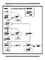
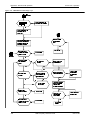
TRS Configuration and Operation . . . . . . . . . . . . . . . . . . . . . . . . . . . . . . . . . . . . 295
TRS Programming/Operation Overview . . . . . . . . . . . . . . . . . . . . . . . . . . . . . . . . . . . . 296
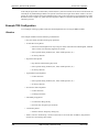
Example TRS Configuration . . . . . . . . . . . . . . . . . . . . . . . . . . . . . . . . . . . . . . . . . . . . . 298
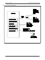
ARS Configuration and Operation . . . . . . . . . . . . . . . . . . . . . . . . . . . . . . . . . . . . 306
ARS/TRS Programming/Operation Overview . . . . . . . . . . . . . . . . . . . . . . . . . . . . . . . . 306
Example ARS Configuration . . . . . . . . . . . . . . . . . . . . . . . . . . . . . . . . . . . . . . . . . . . . . 309
10
DBS 576 (USA), Revised 6/11/98
576-13-700
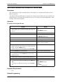
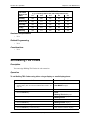
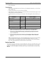
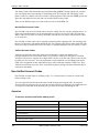
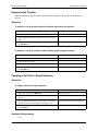
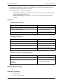
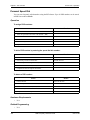
Chapter 1. About This Manual
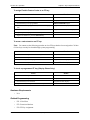
If you are using this manual for a single System, make note of its software version in the following
table. This information may be referenced by technicians or owners of the System.
Software version information for systems shipped with this document
CPC Model:
Software Version:
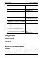
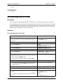
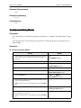
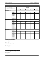
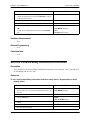
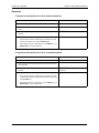
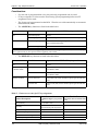
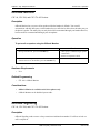
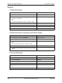
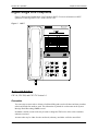
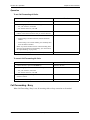
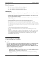
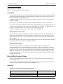
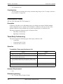
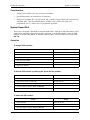
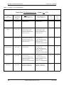
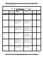
Organization
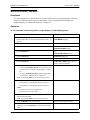
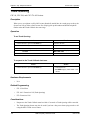
This manual contains detailed descriptions of features. The feature descriptions are organized
according to the following categories:
Feature Categories
Description
System Features
System Features are either available on a systemwide basis or aid in the overall administration of the
System.
User Maintenance Features are used by the end user
to maintain the System. These items include setting
time and date, Personal Speed Dial (PSD) numbers
and names, System Speed Dial (SSD) numbers and
names, extension names, Verified ID codes, Call
Forward ID codes for Voice Mail, Message Key ID
codes, Mode schedule, Special Day mode, Exception Day mode, and Day of Week mode.
Key Telephone Features are available to System Key
phones. System Key phones are proprietary digital
sets that provide feature access through a combination of feature keys and access codes.
DSLT Features are available to Digital Single-Line
Telephones. DSLTs provide digital audio quality and
limited feature key access in a single-line set.
SLT Features are available to industry-standard 2500
sets. Since SLTs are not equipped with feature keys,
most features are accessed by using the dialpad and/
or the switchhook.
User Maintenance
Key Telephone Features
Digital Single-Line Telephone (DSLT) Features
Single Line Telephone
(SLT) Features
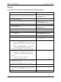
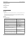
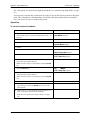
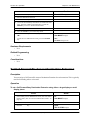
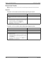
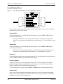
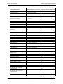
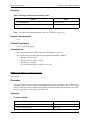
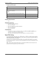
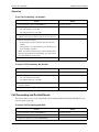
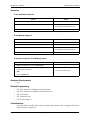
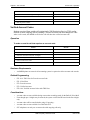
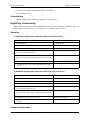
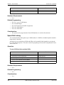
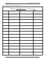
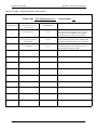
Purpose
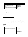
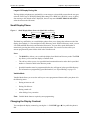
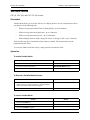
The purpose of this manual is to provide an overview of feature operations and requirements. Where
applicable, the following types of information are provided for each feature:
Types of information
Purpose
Description
Provides an overview of how the feature works and,
in some cases, what it is typically used for
Includes step-by-step instructions on how to use the
feature
Lists any special hardware that is required to use the
feature
Operation
Hardware Requirements
576-13-700
DBS 576 (USA), Revised 6/11/98
11
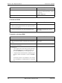
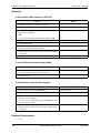
Chapter 1. About This Manual
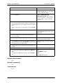
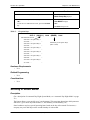
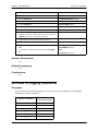
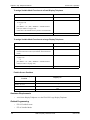
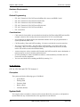
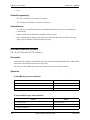
Related Programming
Considerations
Section 700 - Operation
Lists the programming subsystems associated with
the feature
Provides details on feature interactions and limitations
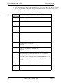
Abbreviation List
ACD
ARS
BGM
BLF
BRI
CFWD
COS
DDI
DIL
DISA
DL
DND
DP
DSLT
DSS
DSU
DTMF
FF
MCO
MOH
PRI
PSD
SLT
SSD
TRS
LCR
12
Automatic Call Distributor
Automatic Route Selection
Background Music
Busy Lamp Field
Basic Rate Interface
Call Forward
Class of Service
Direct Inward Dial
Direct In Line
direct Inward System Access
Direct Line
Do-Not-Disturb
Dial Pulse
Digital Single Line Telephone
Direct Station Selector
Digital Service Unit
Dual Tone Multifrequency
Flexible Function
Multiple CO (Pooled Trunk Access)
Music On Hold
Primary Rate Interface
Personal Speed Dial
Single Line Telephone
System Speed Dial
Toll Restriction Service
Least Cost Routing
DBS 576 (USA), Revised 6/11/98
576-13-700
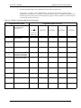
Chapter 2. List of Features
This chapter contains the following tables which list the features available with the System:
Table
Page
System Features
14
Maintenance Features
15
Extension Features
16
576-13-700
DBS 576 (USA), Revised 6/11/98
13
Chapter 2. List of Features
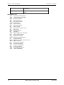
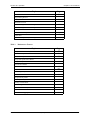
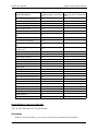
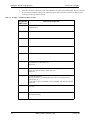
Table 1.
Section 700 - Operation
System Features
Topic
14
Page
AEC Disconnect
22
Attendant Groups
22
Attendant Groups
22
Automatic Call Distributor
23
Automatic Route Selection
24
Automatic Trunk to Trunk Transfer
25
Background Music/MOH Separation
25
Battery Backup
25
Building Block Expansion Capability
26
Built-In Voice Processing Unit
26
Call Progress Tones
27
Caller ID
28
Centrex/PBX Compatibility
28
Class of Service
29
CO Ringing Types
32
CO Trunk Interface
34
Computer Telephony Integration Capability
36
Data Security
37
Day/Night System Mode
37
Digital Pad
40
Direct Inward System Access
40
Distinctive Ringing
41
Door Box
42
Extension Interface
43
Flexible Numbering Plan
45
Free Slot
46
Hunting Groups
46
Internal Hold Tone
48
MCO Tenant Group
48
Memory Backup
49
Music-on-Hold
50
Name Assignments
50
Network Facilities
56
Non-Blocking Architecture
57
Power Failure Transfer
58
DBS 576 (USA), Revised 6/11/98
576-13-700
Section 700 - Operation
Chapter 2. List of Features
Topic
Page
Power On Maintenance
58
Programming Devices
59
Ringing Modes
59
SSD TRS Override
63
Station Message Detail Recording
63
Station Message Detail Recording
63
Ringing Modes
59
Trunk Access Groups
66
Virtual Port
67
Voice Mail Integration (Third Party)
68
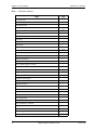
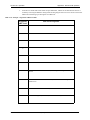
Table 2.
Maintenance Features
Topic
Page
Set System Date/Time/Day
75
Set Personal Speed Dial Numbers
76
Set Personal Speed Dial Names
77
Set System Speed Dial Numbers
82
Set System Speed Dial Names
83
Set Extension Names
86
Set Verified Account Codes
87
Set Call-Forward ID Codes for Voice Mail
89
Set Message Key ID Code
90
Set Mode Schedule
91
Set Special Day Mode
93
Set Exception Day Mode
99
Set Day of Week Mode
101
Set Walking TRS Codes
103
Set Call Forward Busy Destination Extension
104
Set Call Forward No Answer Destination Extension
105
Set Caller ID Logging Extensions
106
576-13-700
DBS 576 (USA), Revised 6/11/98
15
Chapter 2. List of Features
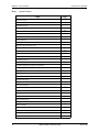
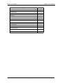
Table 3.
Section 700 - Operation
Extension Features
Topic
16
Page
Account Codes
112
Attendant Group Calls
115
Auto Repeat Dial
116
Background Music
116
Busy Override
117
Callback Request
119
Call Forwarding
120
Call Hold
124
Call Hold
127
Call Pickup
129
Call Transfer
132
Caller ID Call Log
136
Camp-on (Call Waiting)
141
Conference Calls
143
Display Information
145
Do-Not-Disturb
148
DP to DTMF Signal Conversion
150
DSS/72 Console
150
EM/24 Console
151
Flash
151
Flexible Function Keys
152
Handsfree Answerback
157
Handsfree Operation
158
Headset Operation
159
Hot Dial Pad
160
Hot Line
160
Intercom Calling
161
Last Number Redial
162
Line Appearances
163
Message Key
166
Message Waiting / Callback
167
Mute Function
169
Offhook Monitor
170
Offhook Signaling
170
Offhook Voice Announce
171
DBS 576 (USA), Revised 6/11/98
576-13-700
Section 700 - Operation
Chapter 2. List of Features
Topic
Page
One-Touch Keys
173
Onhook Dialing
175
Paging
176
Reset Call
177
Ringing Line Preference
178
Speed Dialing
179
Timed Reminder Call
189
Trunk Access
190
Trunk Queuing
194
Variable Mode
195
Voice Recognition
197
Volume Control
197
Walking TRS Class of Service
198
576-13-700
DBS 576 (USA), Revised 6/11/98
17
Chapter 2. List of Features
18
Section 700 - Operation
DBS 576 (USA), Revised 6/11/98
576-13-700
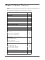
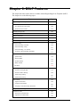
Chapter 3. System Features
System Features are either available on a system-wide basis or aid in the overall administration of the
System.
This chapter contains detailed descriptions of the following System Features:
Topic
Page
AEC Disconnect
22
Attendant Groups
22
Attendant Groups
22
Automatic Call Distributor
23
Automatic Route Selection
24
Automatic Trunk to Trunk Transfer
25
Background Music/MOH Separation
25
Battery Backup
25
Building Block Expansion Capability
26
Built-In Voice Processing Unit
26
Call Progress Tones
27
Caller ID
28
Centrex/PBX Compatibility
28
Class of Service
29
Class of Service - Trunk/Tie
29
Class of Service - Ext/Ext Restriction
30
Class of Service - Extension Feature
30
Class of Service - Trunk to Trunk Restriction
32
CO Ringing Types
32
Direct Inward Dial Ringing
32
Direct In Line Ringing
33
Direct Inward System Access Ringing
33
Multiple Ringing
34
CO Trunk Interface
34
CO Trunk Interface - DID
34
CO Trunk Interface - Ground Start
35
CO Trunk Interface - ISDN BRI
35
CO Trunk Interface - ISDN-PRI
35
CO Trunk Interface - Loop Start
36
Computer Telephony Integration Capability
36
Data Security
37
576-13-700
DBS 576 (USA), Revised 6/11/98
19
Chapter 3. System Features
Section 700 - Operation
Topic
Day/Night System Mode
37
Manual Day/Night Mode
38
Automatic Day/Night Mode
39
Digital Pad
40
Direct Inward System Access
40
Distinctive Ringing
41
Door Box
42
Door Box Sensor
43
Extension Interface
43
Digital Key Telephones
43
Analog Device Capability
44
DP/DTMF Single Line Telephones (SLTs)
44
ISDN/BRI S-Point Interface
44
ISDN/PRI S-Point Interface
45
Flexible Numbering Plan
45
Free Slot
46
Hunting Groups
46
Internal Hold Tone
48
MCO Tenant Group
48
Memory Backup
49
Music-on-Hold
50
Name Assignments
50
Extension Name Assignments
51
Speed Dial Name Assignments
54
Network Facilities
56
Network Call Transfer
57
Network Extension Calling
57
Network Paging
57
Network Call Routing
57
Tandem Connection
57
Non-Blocking Architecture
57
Power Failure Transfer
58
Power On Maintenance
58
Programming Devices
59
PC-Based Customizing Tool
20
Page
59
DBS 576 (USA), Revised 6/11/98
576-13-700
Section 700 - Operation
Chapter 3. System Features
Topic
Ringing Modes
Page
59
Day 1/ Day 2/Night Ringing
60
Day 1/ Day 2/Night Delayed Ringing
60
DID Day/Night Ringing
61
DID Day/Night Busy/Delayed Ringing
61
Busy Lamp Field Ringing
61
Busy Lamp Field Delayed Ringing
62
Slide Ringing
62
Alarm Ringing
62
SSD TRS Override
63
Station Message Detail Recording
63
Trunk Access Groups
66
Virtual Port
67
Virtual Port used for Floating Hold
67
Virtual Port used for Virtual Extension
67
Voice Mail Integration (Third Party)
68
Answer Supervision for Voice Mail
68
Call Forward ID Code for Voice Mail
68
DID/DNIS/DDI Voice Mail ID Code
69
High Priority Message Waiting
70
Message Key ID Code
70
Voice Mail Transfer Key
71
576-13-700
DBS 576 (USA), Revised 6/11/98
21
Chapter 3. System Features
Section 700 - Operation
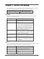
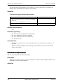
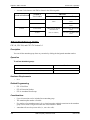
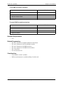
AEC Disconnect
Description
This feature allows the System to send a disconnect signal of 1 second to an analog device indicating
that the calling party has hung up (terminated the call). This feature is useful with a Third-party Voice
Mail or an Answering Machine. By default this feature is disabled.
Hardware Requirements
•
AEC port
Related Programming
•
FF3-0: Loop Disconnect Signal
Considerations
•
The 1 second time duration of the disconnect signal is fixed. (It cannot be changed.)
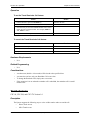
Attendant Groups
CPC-96, CPC-288, and CPC-576 Version 1.0
Description
An attendant phone is often used as a central answering point for other extensions. In addition,
attendant phones frequently have special capabilities for monitoring and programming extensions.
You can reach the assigned attendant group by dialing the feature access code for Attendant Calls
(usually 0). If an attendant phone is available but does not answer within a set time, the call will move
to the next available attendant phone. If all members of the attendant group are busy for a specified
time, the call can be forwarded to other extensions or another hunt group. The system allows up to 20
extensions to be included in an attendant group.
Hardware Requirements
•
N/A
Related Programming
•
•
•
•
•
FF5-0-01: Attendant Hunt Pilot Number
FF5-0-02: Day 1 Attendant Hunting
FF5-0-03: Day 2 Attendant Hunting
FF5-0-03: Night Attendant Hunt
FF2: Ring Type
Considerations
•
•
•
22
The System allows one attendant group for each system mode (Day 1, Day 2, and Night).
An attendant group can contain both real extensions and virtual extensions. If virtual, several
phones can be made to ring at the same time.
Attendant groups can use only Pilot Terminal Hunt Group or Pilot Distributed Hunt Group. For
more information, see “Hunting Groups” on page 46.
DBS 576 (USA), Revised 6/11/98
576-13-700
Section 700 - Operation
•
Chapter 3. System Features
The pilot number for an attendant group is flexible (i.e., any extension number can be designated
as the pilot [not a real extension]).
If a member of the attendant group has Do-Not-Disturb (DND) or Call Forwarding - All set, that
phone is temporarily removed from the attendant group.
If a member of the attendant group has Call Forwarding - Busy set and the extension is busy, the
call goes to the next phone in the attendant group.
If all members are busy for the duration of the busy queuing timer, the call can be forwarded to
another hunt group or another extension.
Attendant groups support the following call types:
• Direct Inward Dialing (DID) / Dialed Number Identification Service (DNIS) / Direct
Dial Inward (DDI)
• Direct Inward System Access (DISA)
• Extension calls
• Private network attendant calls
• Call reversion
• Call forwarded to Attendant Hunt Group
•
•
•
•
Automatic Call Distributor
Description
The System provides an optional Automatic Call Distributor (ACD) for efficient presentation,
handling, and management of incoming calls to one or more groups of specialized users.
This optional Built-in ACD is contained on a single circuit card that is installed in the System. This
“built-in” capability eliminates the need for custom wiring and other installation.
Each specialized user is known as an ACD agent. Each agent position is equipped with a large display
telephone (VB-44225) that provides Liquid Crystal Display (LCD) messages to assist the agent in
handling calls.
The Built-in ACD provides:
•
•
•
•
•
•
•
•
•
•
•
•
•
576-13-700
Up to 2 agent groups
Up to 32 agent IDs per group
Up to 64 agent IDs per system
Up to 32 agents
1 supervisor ID per group
Up to 2 supervisor IDs per system
Up to 4 voice ports per group
Up to 4 voice ports per system
1 Music On Hold (MOH) source (Main System MOH source)
1 Management Information System (MIS) Monitor Port (RS-232C)
2-week memory for MIS reports
Up to 6 recorded messages (max. 14 sec. per message)
1 fixed message up to 5 minutes
DBS 576 (USA), Revised 6/11/98
23
Chapter 3. System Features
Section 700 - Operation
Hardware Requirements
•
See Section 520 - Built-In ACD Reference Manual.
Related Programming
•
See Section 520 - Built-In ACD Reference Manual.
Considerations
•
For more information, see Section 520 - Built-In ACD Reference Manual.
Automatic Route Selection
Description
When Automatic Route Selection (ARS) is enabled, the system follows a preselected route for calls.
Usually the selected routing is the least cost route.
ARS works in conjunction with Toll Restriction Service (TRS). Calls can be denied based on the
programmed TRS level for the originating party. (For more information, see “Ringing Modes” on
page 59.)
•
Three levels of ARS checking are available based on the dialed number following the ARS
access code:
•
Direct Route Selection: The simplest form of ARS routing that upon ARS entry
(enter 9) directly selects the trunk group and any dialed number modification.
•
Route List Selection: A more complex routing that includes up to 5 alternative
levels of route selection and includes TRS level checking.
Time List Selection: The most complex routing that determines the appropriate
route list based upon the day and time.
•
•
•
Forced ARS is available on an Extension Class of Service (COS) basis.
A special day list provides tailored ARS routing for up to 20 holidays, vacation days, etc.
•
•
Automatic modification of dialed numbers is available. This includes deleting up to 24 prefix
digits and adding up to a 10-digit prefix and a 10-digit suffix. The modification of dialed
numbers can include pauses, Dual Tone Multifrequency (DTMF) conversion, itemized code
(extension number) and an authorization code. (Itemized code and authorization are not used
in some areas.)
Up to 8 authorization codes are available.
•
For more information on ARS/TRS, see Appendix A “ARS and TRS Operation” on page 291.
Hardware Requirements
•
N/A
Related Programming
•
N/A
Considerations
•
24
N/A
DBS 576 (USA), Revised 6/11/98
576-13-700
Section 700 - Operation
Chapter 3. System Features
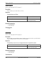
Automatic Trunk to Trunk Transfer
Description
The System can be set to automatically transfer trunk calls out to another trunk without requiring the
call to be answered internally. This transfer may be either trunk based or extension based (i.e., call
forward outside).
Hardware Requirements
•
N/A
Related Programming
•
N/A
Considerations
•
N/A
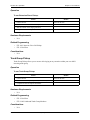
Background Music/MOH Separation
Description
Separate inputs are provided for Background Music and Music-on-Hold (MOH). This allows one
music or sound source to be used for background music and another music or sound source to be used
for music on hold.
A typical advantage of this is playing a pre-recorded promotional tape to held parties (since many
may be customers) while providing a selected background music for use in the office.
Hardware Requirements
•
Background music requires an SCC card (VB-44181). Both Background Music and Music on
Hold (if using external MOH) require a sound source.
Related Programming
•
N/A
Considerations
•
N/A
Battery Backup
Description
When backup batteries are installed, the System will continue to operate in the event of a power
failure. If using Battery Backup, backup batteries must be installed in each cabinet.
A fully loaded system will operate at least 30 minutes on backup batteries.
576-13-700
DBS 576 (USA), Revised 6/11/98
25
Chapter 3. System Features
Section 700 - Operation
Hardware Requirements
•
Back-up battery unit (VB-44025)
Related Programming
•
N/A
Considerations
•
Any device connected to the System but that does not derive its power from the System must
have a backup power source to operate. These devices include any System Message Detail
Recording (SMDR) printer (or recorder), fax machine, answering machine, modem, cordless
telephone, etc.
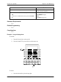
Building Block Expansion Capability
Description
The System is designed to support easy expansion. Each cabinet in the System supports 96 ports (12
flexible slots) as well as 2 option slots. Up to 6 cabinets may be installed in the System for a total of
576 ports.
Up to 2 expansion cabinets may be connected to a base cabinet. When a fourth cabinet is required,
another base cabinet is installed. Up to 2 expansion cabinets may be connected to the second base
cabinet.
This building block approach allows you to easily add equipment when needed without a major
interruption in service or a major delay.
Hardware Requirements
•
N/A
Related Programming
•
N/A
Considerations
•
In addition to the additional cabinets and related cabinet hardware/cabling required for
expansion, when the System is expanded the CPC card and/or TSW cards may need to be
upgraded as well. The CPC96 supports up to 96 ports. The CPC288 supports up to 288 ports and
should be combined with time switch card TSW288. The CPC-576 supports up to 576 ports and
should be combined with time switch card TSW576.
Built-In Voice Processing Unit
Description
The System supports the Built-in Voice Processing Unit. This unit assists in providing reliable,
effective communications. This is a simple device that includes an automated attendant function and
can be used to record conversations (where permitted).
26
DBS 576 (USA), Revised 6/11/98
576-13-700
Section 700 - Operation
Chapter 3. System Features
The Built-in Voice Processing Unit is easy to install. It is installed in a cabinet card slot and no cabling
is required.
Some of the major features include:
•
•
•
•
•
•
•
Automated attendant
Automatic recording for incoming and outgoing calls
One-touch mail box transfer
Mail box status display (Key LED on digital telephone)
Mail box grouping
2-way recording
Outside notification
•
•
•
•
•
•
Date/time stamp
Integrated Liquid Crystal Display (LCD) control (with large LCD telephone)
Message light control
Up to 254 mail boxes
Up to 40 hours of message storage time
Up to 8 voice ports
For more information, see the System Built-In Voice Processing Unit Reference Manual.
Hardware Requirements
•
N/A
Related Programming
•
N/A
Considerations
•
N/A
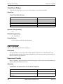
Call Progress Tones
Description
The System supplies a full array of call progress tones. These tones provide audible indications of the
status of calls and include dial tone, busy tone, ringback tone, error tone, confirmation tone, and
splash tone. The complete specification for these tones may be found in Section 300 - Installation.
In addition to call progress tones, Direct Station Select (DSS) LEDs and the display provide
additional indication of the status of calls.
Hardware Requirements
•
N/A
Related Programming
•
N/A
576-13-700
DBS 576 (USA), Revised 6/11/98
27
Chapter 3. System Features
Section 700 - Operation
Considerations
•
N/A
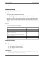
Caller ID
Description
A properly equipped DBS 576 supports Caller ID, a service offered by the network telephone
service provider. The CO sends calling number information to the DBS 576 after the first
ring. Users who have display telephones can see Caller ID information as incoming calls ring
at their extension and can have access to previous calls via the Caller ID Call Log feature.
The Caller ID number is recorded in SMDR.
Hardware Requirements
•
•
Loop-start trunk card (VB-44510)
Caller ID circuit card (VB-44513)
Related Programming
•
•
•
FF2-0: Caller ID
FF2-0: Caller ID Ring Control
FF3-0: Call Duration Display
Considerations
•
•
•
•
•
ISDN (PRI - T Point) can get calling party information.
Caller ID service must be ordered from the local telephone operating company or the
interexchange carrier.
Caller ID data is usually sent between the first and the second rings of the incoming trunk call.
The trunk may be programmed to immediately ring at the station or wait until after the Caller ID
digits are received before ringing at the station. If the trunk is programmed to ring immediately,
the Caller ID digits will not display until after they are received and processed.
Caller ID numbers may be denied from being sent for some callers (private). Some long distance
carriers may not provide Caller ID data (out of area).
Caller ID only support the single format (number only). Multiple format (number and name) is
not supported.
Centrex/PBX Compatibility
Description
Centrex/PBX Compatibility allows the System to be connected behind centrex or PBX lines.
The System supports up to 6 access codes for dialing centrex or a PBX. These access codes allow the
System, System Message Detail Recording (SMDR) output to exclude the number dialed to reach a
centrex or PBX line.
28
DBS 576 (USA), Revised 6/11/98
576-13-700
Section 700 - Operation
Chapter 3. System Features
When connected behind a PBX or Centrex, Toll Restriction Service (TRS) can be used to restrict
calls.
The System also supports transmission of a flash signal over the centrex or PBX link.
Hardware Requirements
•
N/A
Related Programming
•
N/A
Considerations
•
N/A
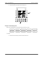
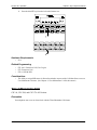
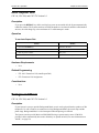
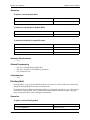
Class of Service
Description
A Class of Service (COS) allows or restricts access to a group of features or functions. For instance,
an Extension COS may allow Call Forwarding features. In the System, both extensions and trunks use
classes of service.
The System supports the following COSs for trunks and extensions:
•
•
•
•
COS - Trunk/Tie
COS - Ext/Ext Restriction
COS - Extension Feature
COS - Trunk to Trunk Restriction
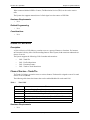
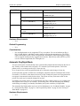
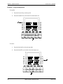
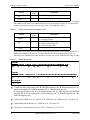
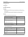
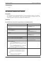
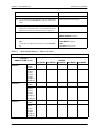
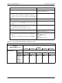
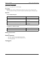
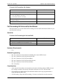
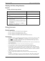
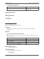
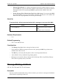
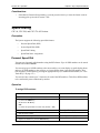
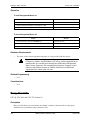
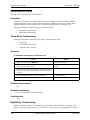
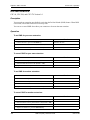
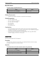
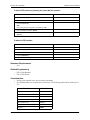
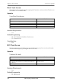
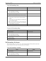
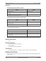
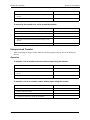
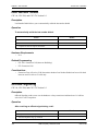
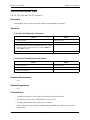
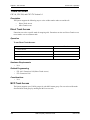
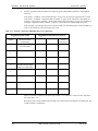
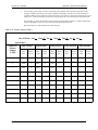
Class of Service - Trunk/Tie
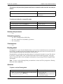
Tie/Trunk COS allows or restricts access to various features. Each trunk is assigned to one of 16 trunk
classes of service (00-15).
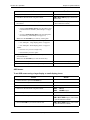
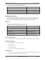
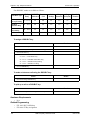
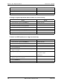
The following table shows the features that can be enabled/disabled for each trunk COS.
Table 4.
Trunk COS
Number
Feature
1
2
3
4
5
6
Intercom Ringing Tone (CO or intercom ring tone)
Dial Tone to Tie Lines (Enable/Disable)
Forced Recover on Fast-Busy Tone (Send fast busy or disconnect line)
DID/DDI Dialed Number Conversion Table (DID/DNIS Table A or B)
Paging on DISA/Tie-Line Call (Allow/Restrict)
DISA ID Verification
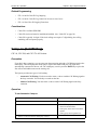
Hardware Requirements
•
N/A
576-13-700
DBS 576 (USA), Revised 6/11/98
29
Chapter 3. System Features
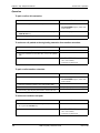
Section 700 - Operation
Related Programming
•
N/A
Considerations
•
N/A
Class of Service - Ext/Ext Restriction
Ext/Ext Restriction COS allows or restricts calls placed to other extensions based upon the Extension
COS. Each Extension COS is programmed to either originate or not originate calls to another
Extension COS.
Hardware Requirements
•
N/A
Related Programming
•
•
•
FF1-0-03: Class of Service - Extension
FF1-0-10: Ext - Ext Restriction
FF2: Extension COS Assignment
Considerations
•
N/A
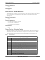
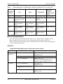
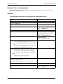
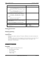
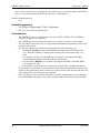
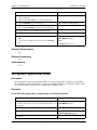
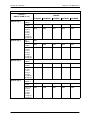
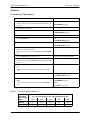
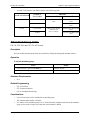
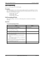
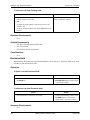
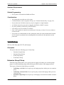
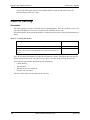
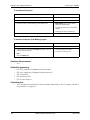
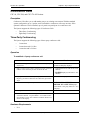
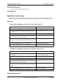
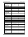
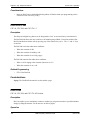
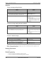
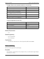
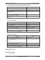
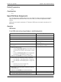
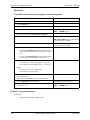
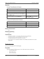
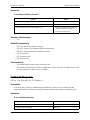
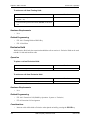
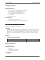
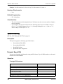
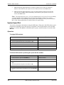
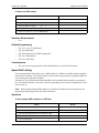
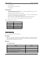
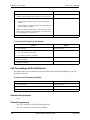
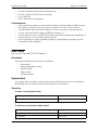
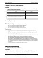
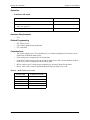
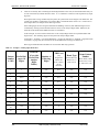
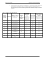
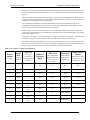
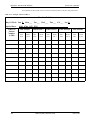
Class of Service - Extension Feature
Extension COS allows or restricts access to certain extension features. (The extension features are
described later in this manual.) Each extension is assigned to one of 16 classes of service (00-15).
The following table shows the features that can be enabled/disabled for each Extension COS.
Table 5.
Extension COS
Class of Service Features
Number
1
2
3
4
5
6
7
8
9
10
11
12
13
30
Feature
Intercom Call Type (Tone/Voice)
Onhook Transfer at Ringback (Allow/Restrict)
Onhook Transfer at Talk (Allow/Restrict)
On-Hook Transfer at Camp-On (Allow/Restrict)
Exclusive Hold for Non-Appearing CO (System/Exclusive)
Exclusive Hold on SLTs (System/Exclusive)
Brokers Hold on SLTs (3-Party Conference/Brokers)
Hookflash During Talk on SLTs (Allow/Restrict)
SSD Assignment (Allow/Restrict)
SSD Assignment to MCO Tenant Groups (Allow/Restrict)
SSD Dialing (Allow/Restrict)
Intercom Redialing (Allow/Restrict)
Direct Trunk Access (Allow/Restrict)
DBS 576 (USA), Revised 6/11/98
576-13-700
Section 700 - Operation
Chapter 3. System Features
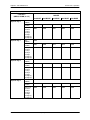
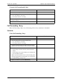
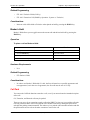
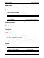
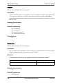
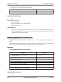
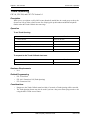
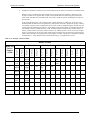
Class of Service Features
576-13-700
14
MCO Incoming Call Answer (Allow/Restrict)
15
Paging (Allow/Restrict)
16
Auto Repeat Dial (Allow/Restrict)
17
DND Set/Clear (Allow/Restrict)
18
DND Set/Clear (Other) (Allow/Restrict)
19
Call Forward/All Calls (Allow/Restrict)
20
Call Forward/No Answer (Allow/Restrict)
21
Call Forward-Busy (Allow/Restrict)
22
Call Forward (Other) (Allow/Restrict)
23
User Maintenance Log-in (Allow/Restrict)
24
Priority Message Waiting Send (VM) (Allow/Restrict)
25
Message Waiting Send (Allow/Restrict)
26
System Mode Switch (Allow/Restrict)
27
Busy Override Send (Allow/Restrict)
28
Manual Camp-On Send (Allow/Restrict)
29
Manual Camp-On Receive (Allow/Restrict)
30
Callback Request Send (Allow/Restrict)
31
Callback Request Receive (Allow/Restrict)
32
Trunk Queuing (Allow/Restrict)
33
Manual DND Override Send (Allow/Restrict)
34
Forced DND Override (Allow/Restrict)
35
8-Party Conference (Allow/Restrict)
36
Voice Call Send (Allow/Restrict)
37
Voice Call Receive (Allow/Restrict)
38
Dial Tone Stop (Allow/Restrict)
39
Dial Tone Pre-Pause Check (Check/No check)
40
Long Talk Alarm for Outgoing CO Calls (Enable/Disable)
41
Recall Timer Apply (Recall to Extension/Recall to Attendant)
42
Forced ARS (Not Forced/Forced)
43
API Event Reporting (No/Yes)
44
Call Forward/Outside (Allow/Deny)
45
Onhook Trunk-to-Trunk Transfer (Allow/Deny)
46
Station Call Park Answer (Allow/Deny)
47
Station Call Park Transfer (Allow/Deny)
48
OHVA (Allow/Deny)
DBS 576 (USA), Revised 6/11/98
31
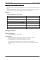
Chapter 3. System Features
Section 700 - Operation
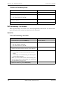
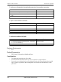
Class of Service Features
49
OHVA Answer (Allow/Deny)
50
Call-Waiting Answer at HOLD
Hardware Requirements
•
N/A
Related Programming
•
•
FF2: Trunk COS
FF3: Extension COS Assignments
Considerations
•
N/A
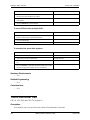
Class of Service - Trunk to Trunk Restriction
Trunk to Trunk COS allows or restricts call transfers from one trunk to another trunk based on the
originating and receiving trunk COS.
Hardware Requirements
•
N/A
Related Programming
•
•
FF1-0-04: Class of Service Trunk/Tie
FF1-0-11: Trunk-Trunk Restriction
Considerations
•
N/A
CO Ringing Types
Description
Several types of CO ringing are available for the System including the following:
•
•
•
•
Direct Inward Dialing (DID) Ringing
Direct In Line (DIL) Ringing
Direct Inward System Access (DISA) Ringing
Multiple Ringing
These ringing types may be used in any combination in the System.
Direct Inward Dial Ringing
DID Ringing allows calls on a common CO to be directed to ring to a specific extension or group of
extensions, etc. based upon the final digits dialed. These final digits are received from the DID trunk
and compared to a DID Table that determines where the calls should ring. Depending on the
32
DBS 576 (USA), Revised 6/11/98
576-13-700
Section 700 - Operation
Chapter 3. System Features
assignments in the DID Table, names or trunk numbers are displayed. (Names can be up to 10 digits
long.)
DID Ringing can be very useful by sending calls directly to a specific extension, hunt group, etc.
based upon the number dialed. Since a relatively small number of trunks handle the DID calls, this
can be more cost efficient than DIL trunks or attendant group answering and transfer. (DID may send
a call to a group using the Virtual Extension feature.) DID Busy/Delayed Ringing is also available
with DID Ringing. (See “DID Day/Night Busy/Delayed Ringing” on page 61.)
For more information on DID CO Trunk Interface, see “CO Trunk Interface - DID” on page 34.
Hardware Requirements
•
N/A
Related Programming
•
N/A
Considerations
•
Caller ID takes priority over the DID name assignment.
•
Only one of the two DID tables may have name assignments.
Direct In Line Ringing
DIL Ringing allows calls on a specific CO line to be directed to ring a specific extension, System
Speed Dial (SSD) number (for redirecting calls out), and hunting group.
This can be very useful when a trunk is dedicated to a specific person or purpose. However, this can
be a more expensive use of the line since it has a more limited use.
Hardware Requirements
•
N/A
Related Programming
•
N/A
Considerations
•
N/A
Direct Inward System Access Ringing
DISA Ringing (which is related to the DISA feature) allows a CO trunk specified as a DISA CO trunk
to ring and give off-site users dial-in access to the System. Once the DISA trunk is accessed, the user
receives dial tone and may dial an extension.
For more information on DISA, see “Direct Inward System Access” on page 40.
Hardware Requirements
•
N/A
Related Programming
•
N/A
576-13-700
DBS 576 (USA), Revised 6/11/98
33
Chapter 3. System Features
Section 700 - Operation
Considerations
•
N/A
Multiple Ringing
CPC-96, CPC-288, and CPC-576 Version 1.0
Description
Multiple Ringing allows CO calls into the System to be directed to ring multiple extensions in the
System. This can be very useful when anyone in a group may answer a call. This can also be very
useful at night when only a selected number of people are available to handle calls.
Hardware Requirements
•
N/A
Related Programming
•
N/A
Considerations
•
N/A
CO Trunk Interface
Description
The System supports several types of CO Trunk Interfaces including the following:
•
•
•
•
Direct Inward Dialing (DID)
Integrated Services Digital Network (ISDN) - Basic Rate Interface (BRI)
ISDN - Primary Rate Interface (PRI)
Loop Start and Ground Start
Each trunk type supports various features such as Delayed Ringing, Night Ringing, etc.
CO Trunk Interface - DID
The DID feature allows an extension to have a dedicated direct number. The dedicated number allows
calls to be made directly to the extension, without the caller going through the attendant.
The DID number may have from 1 to 4 digits (typically 4).
Each DID Trunk Interface card (VB-44520) supports up to 8 DID trunks.
Hardware Requirements
•
The -48V power supply is required.
Related Programming
•
34
N/A
DBS 576 (USA), Revised 6/11/98
576-13-700
Section 700 - Operation
Chapter 3. System Features
Considerations
•
•
The DID Trunk card supports 1 to 4-digit dial-pulse (10 pps) or Dual Tone Multifrequency
(DTMF) signaling.
DID numbers must be between 0 and 9999.
CO Trunk Interface - Ground Start
Ground start trunks are supported in the System with the VB-44511 Loop Start/Ground Start trunk
interface. Each card supplies 8 circuits that can be individually configured for either loop start or
ground start operation.
Ground start trunks are useful in preventing call collision.
Hardware Requirements
•
When ground start trunks are used, the -48V power supply is required.
Related Programming
•
N/A
Considerations
•
N/A
CO Trunk Interface - ISDN BRI
The System supports ISDN BRI with the VB-44530 ISDN BRI interface unit. The VB-44530 is a TPoint ISDN-BRI that supports 2 B (bearer) channels and 1 D (data) channel (2B + D; 192kbps). This
unit connects to an ISDN Data Service Unit (DSU). Point-to-point and point-to-multi operations are
selectable.
The ISDN-BRI supports enblock setting and enblock setting at the sub-address.
Hardware Requirements
•
N/A
Related Programming
•
N/A
Considerations
•
A DSU is required (not available from Panasonic).
CO Trunk Interface - ISDN-PRI
The System supports ISDN-PRI with the VB-44540 ISDN PRI Interface unit. The VB-44540 is a T/SPoint ISDN-PRI that supports 23 B (bearer) channels and 1 D (data) channel (23B + D; 1544kbps).
This unit connects to an ISDN DSU.
Up to 3 units may be installed in a cabinet if you use full channel (23B + D or 24 B). A maximum of
18 units may be utilized in a fully equipped system. When all 24 channels on a unit are utilized, 3 slot
positions are required.
Hardware Requirements
•
N/A
576-13-700
DBS 576 (USA), Revised 6/11/98
35
Chapter 3. System Features
Section 700 - Operation
Related Programming
•
N/A
Considerations
•
N/A
CO Trunk Interface - Loop Start
The VB-44510 Loop Start interface unit supplies 8 loop start analog trunks circuits. In addition, the
VB-44511 Loop Start/Ground Start interface unit may alternatively be used to connect to loop start
trunks.
Hardware Requirements
•
N/A
Related Programming
•
N/A
Considerations
•
N/A
Computer Telephony Integration Capability
Description
Computer Telephony Integration (CTI) provides communication and coordination of operation
between computers and the telephone system. A System Telephony Application Programming
Interface (TAPI) module is available to connect extensions to Microsoft windows-based applications.
The TAPI desktop module enables the capabilities of first party call control. With this module there is
a physical connection between your telephone line and PC. Service Provider Interface (SPI) software
must be installed on the PC to enable the capabilities of TAPI on the System for each specially
enabled telephone. Typical desktop applications include Contact Managers, Personal Organizers, and
Personal Answering Machines.
Hardware Requirements
•
N/A
Related Programming
•
N/A
Considerations
•
36
N/A
DBS 576 (USA), Revised 6/11/98
576-13-700
Section 700 - Operation
Chapter 3. System Features
Data Security
Description
If you are using a line for data (modem connections, etc.), Data Security makes it possible to prevent
interruptions. Data Security can be implemented for either all phone use or outside line use.
Hardware Requirements
•
N/A
Related Programming
•
N/A
Considerations
•
N/A
Day/Night System Mode
Description
Day/Night System Mode enables you to switch the System between two Day modes and a Night
mode. These modes determine incoming call handling, Toll Restriction Service (TRS) call handling,
and attendant group support.
While in a Night mode (generally used at night or any time when your office is closed), incoming
calls can ring at selected extensions (e.g., a night watchman’s extension or an extension connected to
an answering machine). Outbound calls can be restricted to certain phones. Calls can be directed to a
nighttime attendant group instead of the normal daytime attendant group.
The System provides one Night mode for night call handling. However, there are three night feature
access codes (Night, Night 1, and Night 2). These three codes may be used to provide different twoway Voice Processing Unit messages (i.e., Night may select one message, Night 1 may select a
different message, and Night 2 may select a third message.)
Typically, the Day mode is used for normal call processing of outside calls, TRS calls, and attendant
calls. The second day mode (Day 2) may be used for alternative call handling such as during a lunch
break, etc.
There are two ways to change day/night service modes:
•
Manually
•
Automatically
The following table lists the impact on TRS, Ringing, Attendant, and Built-in Voice Processing Unit
in the various system modes:
576-13-700
DBS 576 (USA), Revised 6/11/98
37
Chapter 3. System Features
Table 6.
Section 700 - Operation
System Mode Impact on TRS, Ringing, Attendant, and Built-in Voice Processing Unit
SYSTEM
MODE
TRS
RING
ATTENDANT
BUILT-IN
VOICE
PROCESSING
UNIT
Day 1
Day TRS Mode
Day 1 Ring Pattern
Day 1 Attend. Group
Day 1 Message
Day 2
Day TRS Mode
(Same for Day 1 and
Day 2)
Day 2 Ring Pattern
Day 2 Attend. Group
Handling
Day 2 Message
Night
Night TRS Mode
(Same for Night 1,
and 2)
Night Ring Pattern
(Same for Night 1,
and 2)
Night Attend. Group
(Same for Night 1,
and 2)
Night Message
Night 1
Night TRS Mode
(Same for Night 1,
and 2)
Night Ring Pattern
(Same for Night 1,
and 2)
Night Attend. Group
(Same for Night 1,
and 2)
Night 1 Message
Night 2
Night TRS Mode
(Same for Night 1,
and 2)
Night Ring Pattern
(Same for Night 1,
and 2)
Night Attend. Group
(Same for Night 1,
and 2)
Night 2 Message
Manual Day/Night Mode
You can manually change the System mode to Day 1, Day 2, Night, Night 2, or Night 3 mode by
either entering the correct dial code or by pressing the appropriately programmed FF key.
When using manual mode, the System may be configured to either use MCO tenant Day/Night modes
or system-wide Day/Night mode.
Operation
To switch Day/Day 2/Night modes using Feature Access Codes:
Switch Mode
Toggle Day and
Night Modes
Procedure
1. Press the ON/OFF key.
Indication
Intercom dial tone
ON/OFF LED lights
2. Enter 760.
3. Press the ON/OFF key
ON/OFF LED goes off
If changing to Night mode, Red LED lights
If changing to Day mode, Red LED goes off
Day 2 Mode
1. Press the ON/OFF key.
Intercom dial tone
ON/OFF LED lights
2. Enter 761 for the Day 2 Feature
code.
3. Press the ON/OFF key
ON/OFF LED goes off
Red LED goes off
38
DBS 576 (USA), Revised 6/11/98
576-13-700
Section 700 - Operation
Switch Mode
Night 1 Mode
Chapter 3. System Features
Procedure
1. Press the ON/OFF key.
Indication
Intercom dial tone
ON/OFF LED lights
2. Enter 762 for the Night 1 Feature
code.
3. Press the ON/OFF key
ON/OFF LED goes off
Red Night LED goes off
Night 2 Mode
1. Press the ON/OFF key.
Intercom dial tone
ON/OFF LED lights
2. Enter 763 for the Night 2 Feature
code.
3. Press the ON/OFF key
ON/OFF LED goes off
Red Night LED goes off
Hardware Requirements
•
N/A
Related Programming
•
N/A
Considerations
•
Day and Night modes can be assigned to FF keys on a phone. You can switch between Day 1,
Day 2, Night, Night 1, and Night 2 modes simply by pressing the appropriate key. The FF key
lights red when the System is in the assigned mode. Alternatively a Day/Night toggle mode key
can be assigned. Pressing the key toggles between modes. When in Day mode, the FF key LED
is not lit. When in Night mode, the LED lights red.
Automatic Day/Night Mode
You can set the System to automatically enter a particular Day/Night mode determined by the time of
day. Each day of the month can be assigned 1 of 3 automatic system mode patterns. Each of the
patterns can be set to change modes up to 5 times per day.
Up to 20 special days can be programmed with up to 5 automatic mode changes for the day.
An Exception Day period is available for overriding the automatic mode for extended periods of time.
For instance, if an office is shut down for the week of July Fourth, the System can be programmed to
not operate in the automatic mode for those days. The System will stay in the same mode for the
period. The mode may be manually changed at any time.
For instance, the System can be set to automatically enter Day 1 mode at 8:00 a.m. on weekdays and
enter Night mode at 5:00 p.m. on weekdays. All incoming calls, TRS and attendant group handling
would change accordingly. On Saturday and Sunday, the System would stay in Night mode.
The Automatic Day/Night modes may be set in User Maintenance. See “Set Mode Schedule” on page
91, “Set Special Day Mode” on page 93, “Set Exception Day Mode” on page 99, and “Set Day of
Week Mode” on page 101.
Hardware Requirements
•
N/A
576-13-700
DBS 576 (USA), Revised 6/11/98
39
Chapter 3. System Features
Section 700 - Operation
Related Programming
•
N/A
Considerations
•
You can only set Automatic Day/Night modes on a system-wide basis. If tenant groups require
separate Day/Night modes, you must set these modes manually.
•
You can manually override Automatic Day/Night modes. (See “Manual Day/Night Mode” on
page 38.)
Digital Pad
Description
Digital pad settings allow adjustment of call levels for different call types. There are 29 pad classes in
the System. For pad class, a volume adjustment is assigned for a connection to any pad class
assignment. The volume adjustment is between -30dB and +30 dB.
There are 8 extension pad classes and 16 trunk pad classes. In addition, there are pad classes for
conference calls, page port, MFR, RAI Modem, and Conference Call Unit. One pad class is currently
not used.
For instance, a call from an extension assigned to extension pad class 1 to a trunk assigned to trunk
pad class 3 would received the volume adjustment assigned to this connection combination.
Hardware Requirements
•
N/A
Related Programming
•
N/A
Considerations
•
N/A
Direct Inward System Access
(All Versions)
Description
Direct Inward System Access (DISA) gives off-site users dial-in access to the System. You access
DISA from an outside location by entering a digit number assigned to a DISA trunk.
For security reasons, sixteen incoming DISA ID codes/TRS class can be assigned. If a code is
assigned, it must be entered as soon as the DISA trunk answers.
40
DBS 576 (USA), Revised 6/11/98
576-13-700
Section 700 - Operation
Chapter 3. System Features
Operation
To make a DISA call to an extension:
Action
1. From an outside location, enter the DISA trunk number.
Result
DISA dial tone
2. If an incoming DISA code is assigned enter the DISA code
(up to 10 digits). Otherwise, proceed to step 3.
3. Dial the extension number.
To make a DISA call to an outside number:
Action
1. From an outside location, enter the DISA trunk number.
Result
DISA dial tone
2. If an incoming DISA code is assigned enter the DISA code
(up to 10 digits). Otherwise, proceed to step 3.
3. Enter the Trunk group number (9 or 81-84)
4. Dial the phone number.
Hardware Requirements
• N/A
Related Programming
• FF1-0-26: DISA Incoming Code
•
•
•
FF1-0-26: DISA Outgoing Codes and TRS Assignments
FF1-0-04: Class of Service (DISA ID Check)
FF2: Ring Type
Considerations
•
•
•
•
Busy override cannot be used for a DISA line.
DISA can be used to access extensions as well as outside numbers.
Paging cannot be accessed from a DISA line.
While dialing an extension number, the * key may be entered to cancel dialing and return to dial
tone. The # key may be entered to disconnect.
Distinctive Ringing
Description
Distinctive Ringing sets CO calls to ring with a distinctive ring based on the trunk. This “ring” also
identifies the call as an outside call instead of an inside call.
576-13-700
DBS 576 (USA), Revised 6/11/98
41
Chapter 3. System Features
Section 700 - Operation
Hardware Requirements
•
N/A
Related Programming
•
N/A
Considerations
•
N/A
Door Box
Description
The door box (also called door phone) allows visitors to announce their presence from the office door,
etc. When the button on the door box is pressed, one or more phones ring in the System. When
answered, a two way conversation is made between the door box and the answering phone.
The answering party can operate a connected door opener (if equipped).
Operation
To answer a door box:
Action
Result
1. Answer the door box. (Door box calls ring in on a dedicated
FF key.)
Two way conversation possible
2. Enter 3 while connected to the door box extension.
Door unlocks
Hardware Requirements
•
The door box requires a Door Box Adaptor (VB-43701), Door Box (VA-43705), and Door
Opener. Door openers are not sold by Panasonic; however, they can be purchased from an
electronics dealer.
•
Up to 2 Door Boxes can be connected to a Door Box Adaptor and utilize the same trunk.
•
The Door Opener can be set to open for 15 seconds, 30 seconds, or one minute.
•
While the Door Opener is functioning, a call from another Door Box on the same Door Box
adaptor cannot be answered.
Related Programming
•
N/A
Considerations
•
42
The trunk connected to the Door Box Adaptor must be set to dial pulse (DP).
DBS 576 (USA), Revised 6/11/98
576-13-700
Section 700 - Operation
Chapter 3. System Features
Door Box Sensor
The sensor is a device that detects when a circuit is opened or closed. Sensors can be used to detect
events such as the opening of windows or doors. When the sensor is tripped, a tone sounds at a
designated extension. Sensors are not sold by Panasonic; however, they can be purchased separately
from an electronics dealer.
Hardware Requirements
•
•
The sensor is attached to the Door Box Adaptor (VB-43701).
Trunk lines connected to the Door Box Adaptor signal the designated extension when the sensor
is tripped.
Related Programming
•
N/A
Considerations
•
The trunk connected to the sensor must be a dial-pulse (DP) trunk.
Extension Interface
The System supports a full array of extension devices including the following:
•
•
•
•
•
Panasonic’s proprietary key telephones
Standard analog devices
Dial Pulse (DP) / Dual Tone Multifrequency (DTMF) Single Line Telephone (SLT)
Integrated Services Digital Network (ISDN) - Basic Rate Interface (BRI) S-point devices
ISDN-Primary Rate Interface (PRI) S-point devices
Digital Key Telephones
The System supports the complete line of Panasonic proprietary 44-Series Digital Key Telephones as
well as the Digital Single Line Telephone (DSLT). These models include:
•
•
•
•
•
•
•
•
•
•
16 Button Standard Telephone in Gray (VB-44210G) and Black (VB-44210B)
22 Button Standard Telephone in Gray (VB-44220G) and Black (VB-44220B)
22 Button Display Speakerphone in Gray (VB-44223G) and Black (VB-44223B)
22 Button Voice Response Compatible Display Speakerphone in Gray (VB-44224G) and
Black (VB-44224B)
22 Button Large-display Speakerphone in Gray (VB-44225G) and Black (VB-44225B)
34 Button Standard Telephone in Gray (VB-44230G) and Black (VB-44230B)
34 Button Display Speakerphone in Gray (VB-44233G) and Black (VB-44233B)
EM24 - 24 Button Expansion Module in Gray (VB-44310G) and Black (VB-44310B)
DSS 72 - 72 Button DSS/BLF in Gray (VB-44320G) and Black (VB-44320B)
DSLT (VB-41200)
In addition to the above Digital Key Telephone models, the System supports the complete line of the
older Panasonic proprietary 43-series telephones.
For information on Key Telephone features and operation, see Chapter 5 of this manual. For
information on the DSLT features and operation, see Chapter 6 of this manual.
576-13-700
DBS 576 (USA), Revised 6/11/98
43
Chapter 3. System Features
Section 700 - Operation
Hardware Requirements
•
N/A
Related Programming
•
N/A
Considerations
•
N/A
Analog Device Capability
The System supports analog telephone devices. These devices include fax machines, answering
machines, cordless telephones, computer modems as well as standard rotary and push button
telephones. This provides full flexibility in configuring the System.
Hardware Requirements
•
Analog devices must be connected to an analog port.
Related Programming
•
N/A
Considerations
•
N/A
DP/DTMF Single Line Telephones (SLTs)
The System supports both DP (rotary dial) and DTMF (push button) analog extension types.
Hardware Requirements
•
N/A
Related Programming
•
N/A
Considerations
•
The CPC card provides 4 DTMF receivers. Traffic levels may require that one or more MFR
(DTMF) circuit cards be installed. Each MFR card provides 8 DTMF decoders.
ISDN/BRI S-Point Interface
The System supports ISDN-BRI terminal devices for connection as extensions. The BRI provides 2 B
(bearer) plus 1 D (data) channel support (2B +D; 192 kbps).
Hardware Requirements
•
N/A
Related Programming
•
44
N/A
DBS 576 (USA), Revised 6/11/98
576-13-700
Section 700 - Operation
Chapter 3. System Features
Considerations
•
N/A
ISDN/PRI S-Point Interface
The System supports ISDN-PRI terminal devices with the ISDN/PRI S Point Interface (VB-44540).
The PRI provides 23 B (bearer) plus 1 D (data) channel support (23B +D; 1544 kbps).
Either 8, or 16 or 24 circuits may be enabled on the interface. Each enabled group of 8 circuits
requires a slot position in the System. A fully used card uses 3 slot positions.
Hardware Requirements
•
N/A
Related Programming
•
N/A
Considerations
•
N/A
Flexible Numbering Plan
Description
The System provides flexible numbering for feature access special numbers and extension numbers.
The dialing plan allows settings for digits dialed at dial tone, digits dialed at ringback tone, digits
dialed at busy tone, two patterns of feature codes dialed at dial tone, two patterns of feature codes
dialed at ringback tone, and two patterns of feature codes dialed at busy tone.
Feature access codes can be used when replacing another PBX system with a DBS 576 system. Rather
than learning the new access codes, the System feature access codes can be changed to match the old
system. As a result, telephone users are less confused by the change and the requirement for retraining
is reduced. Two sets of feature access codes are available (one of the two must be assigned to the
terminal).
Hardware Requirements
•
N/A
Related Programming
•
N/A
Considerations
•
N/A
576-13-700
DBS 576 (USA), Revised 6/11/98
45
Chapter 3. System Features
Section 700 - Operation
Free Slot
Description
Each cabinet in the System contains 12 free (universal) slots. These slots can be used for trunk cards,
extension cards, or certain option cards.
Some circuit cards such as the Integrated Services Digital Network (ISDN) - Primary Rate Interface
(PRI) card occupy more that one slot.
Hardware Requirements
•
N/A
Related Programming
•
N/A
Considerations
•
N/A
Hunting Groups
Description
Hunting allows calls to be automatically transferred among a preselected group of phones. If a phone
is busy or there is no answer in a set amount of time, the call will hunt to the next phone in the hunt
group.
A phone assigned to a hunt group is called a member. Up to 20 members can be assigned to a hunt
group. Up to 12 hunt groups are available per cabinet.
Several methods of station hunting are available. Some methods require use of a pilot number (a
fictitious extension number) while others start by a direct call to a hunt group member.
The System supports the following hunting groups:
•
•
•
•
•
Pilot Terminal Hunt Group
Pilot Distributed Hunt Group
Switch Back Hunt Group
Circular Hunt Group
Next Extension/Hunt Group
Pilot Terminal Hunt Group
Pilot Terminal Hunt Group directs calls to a pilot number. The System begins with the first member
and hunts through the group for the first available member to receive the call. If no member is
available (extension is busy or there is no answer for a specified amount of time), the call is queued
for the first member to become available. You can also set the Queuing Timer to specify how long the
System will search the initial hunt group before beginning to search the next hunt group or extension.
The main advantage of this type of hunting is that the same hunting order is taken for all calls. This is
useful in presenting calls to selected members first.
46
DBS 576 (USA), Revised 6/11/98
576-13-700
Section 700 - Operation
Chapter 3. System Features
Pilot Distributed Hunt Group
Pilot Distributed Hunt Group directs calls to a pilot number. The System reviews who received the
last call and begins hunting with the next member. If the last member in the group is reached and no
member is available, the hunt continues with the first member and proceeds forward. After a complete
search and no available member is found (extension is busy or there is no answer for a specified
amount of time), the call is queued for the first member to become available. You can also set the
Queuing Timer and specify how the long the System will search the initial hunt group before
beginning to search the next hunt group or extension.
The main advantage of this type of hunting is that calls are evenly distributed throughout the group.
Switch Back Hunt Group
Switch Back Hunt Group initiates hunting in a specified group for calls made to a member extension
in the group. If the called member of the hunt group is busy, the System begins hunting forward to the
end of the group. If no member is available, the system hunts backward from the called member. If no
member is available (extension is busy or there is no answer for a specified amount of time), the call
is queued for the first member to become available. You can also set the Queuing Timer and specify
how the long the System will search the initial hunt group before beginning to search the next hunt
group or extension.
The main advantage of this type of hunting is that calls can be directed to start with a selected portion
of the hunting group based on the directed number. However, all members are eventually searched.
Circular Hunt Group
Circular Hunt Group initiates hunting in a specified group for calls made to a member extension in the
group. If the called member of the hunt group is busy, the System begins hunting forward to the end of
the group and then moves forward from the first member of the group. If no member is available
(extension is busy or there is no answer for a specified amount of time), the call is queued for the first
member to become available. You can also set the Queuing Timer and specify how the long the
System will search the initial hunt group before beginning to search the next hunt group or extension.
The main advantage of this type of hunting is that calls can be directed to start with a selected portion
of the hunting group based on the directed number. However, all members are eventually searched.
Next Extension/Hunt Group
Next Extension/Hunt Group lets you specify which extension or hunt group to search after the
Queuing Timer expires. This hunt group can be set as any type of hunt group, an attendant group, or
an extension (including virtual extensions).
Hardware Requirements
•
N/A
Related Programming
•
•
•
•
•
•
FF5-1: Hunt Groups Mode
FF5-1: Pilot Number
FF5-1: Member
FF5-1: Delayed Hunt Timer
FF5-1: Queuing Timer
FF5-1: Next Hunting
576-13-700
DBS 576 (USA), Revised 6/11/98
47
Chapter 3. System Features
Section 700 - Operation
Considerations
•
If a member of the hunt group has Do-Not-Disturb (DND) or Call Forwarding - All set, that
phone is temporarily removed from the hunt group.
•
If a member of the hunt group has Call Forwarding - Busy set and the extension is busy, the call
goes to the next phone in the hunt group.
•
If all members are busy for the duration of the busy queuing timer, the call can be forwarded to
another hunt group or another extension.
•
A hunt group can contain both real extensions and virtual extensions. If virtual, several phones
can be made to ring at the same time.
•
The pilot number for a hunt group is flexible (i.e., any extension number can be designated as the
pilot [not a real extension]).
•
Hunt groups support the following call types:
• Direct Inward Dialing (DID) / Dialed Number Identification Service (DNIS) / Direct
Dial Inward (DDI)
• Direct Inward System Access (DISA)
• Extension calls
• Private network attendant calls
• Call forward incoming
• Call forwarded to Attendant Hunt Group
Internal Hold Tone
Description
If a Music-on-Hold (MOH) sound source is unavailable, a periodic hold tone generated internally in
the System can be provided to a caller. For more information, see “Music-on-Hold” on page 50.
Hardware Requirements
•
N/A
Related Programming
•
FF1: MOH Assignment
Considerations
•
N/A
MCO Tenant Group
Description
When the System is configured for tenant operation, MCO Tenant Group determines which trunks
groups are used for incoming and outgoing calls.
48
DBS 576 (USA), Revised 6/11/98
576-13-700
Section 700 - Operation
Chapter 3. System Features
Each MCO trunk group is assigned to an MCO tenant group for incoming calls and for outgoing calls.
By default, Trunk Group 1 is assigned to MCO Tenant Group 1, Trunk Group 2 is assigned to MCO
Tenant Group 2, etc. for both incoming and outgoing calls.
For outgoing calls, each tenant group has 5 auto-trunk selections available. By default the first autotrunk selection is seized by entering 9, the second by entering 81, etc.
The number of MCO tenant groups available depends on the number of ports in the system as follows:
•
•
•
•
•
•
96-port system: ....1 to 12 MCO tenant groups
192-port system: ...1 to 24 MCO tenant groups
288-port system: ...1 to 36 MCO tenant groups
384-port system: ...1 to 48 MCO tenant groups
480-port system: ...1 to 60 MCO tenant groups
576-port system: ...1 to 72 MCO tenant groups
Hardware Requirements
•
N/A
Related Programming
•
•
•
•
•
FF1-3: MCO Incoming/Outgoing
FF5-2: MCO Outgoing Trunk Assignments
FF5-3: MCO Incoming Trunk Assignments
FF2: Trunk Tenant Group Assignments
FF3: Extension Tenant Group Assignments
Considerations
•
When you first assign a trunk to a Trunk Tenant Group from the initial setting of (0), the system
automatically assigns the trunks as a member of the same number MCO Trunk Group (FF5-2 and
FF5-3). For instance, if Trunk 10 is assigned as a member of Trunk Tenant Group 1, then Trunk
10 is automatically assigned as a member of MCO Outbound Trunk Group 1 and MCO Inbound
Trunk Group 1. These assignments can be manually changed if desired.
Memory Backup
Description
Data stored in the CPC card can be copied to another CPC card in the OP2 card slot for the first
cabinet. This is particularly useful when performed after completion of initial system setup (as a
recovery measure) or before major changes are made to system configuration. This backup CPC can
then be used to immediately restore system operation.
This feature is a maintenance feature to be performed by the System certified dealer only.
Hardware Requirements
•
A second CPC card that matches the type installed must be used to copy the memory.
Related Programming
•
N/A
576-13-700
DBS 576 (USA), Revised 6/11/98
49
Chapter 3. System Features
Section 700 - Operation
Considerations
•
N/A
Music-on-Hold
Description
The System can provide Music-on-Hold (MOH) to parties on hold (either CO line, extension, or
network party). The MOH feature can also be used to play announcements or advertisements if
desired.
Hardware Requirements
•
The music source must be purchased separately. It is not provided with the System.
Related Programming
•
N/A
Considerations
•
Important: A license may be required from the American Society of
Composers, Authors, and Publishers (ASCAP) or similar organizations to
transmit radio or recorded music through the MOH feature. Panasonic
Telecommunication Systems Company, its distributors, and affiliates
assume no liability should users of Panasonic equipment fail to obtain
such a license.
Name Assignments
CPC-96, CPC-288, and CPC-576 Version 1.0
Description
Names may be assigned to the following:
•
Extensions
•
Trunks
•
DIDs
•
Personal Speed Dials
•
Systems Speed Dials
Trunks names and DID names must be assigned in dealer programming mode. Extension names and
Speed Dial names may be assigned from a display telephone.
This feature does not require the use of a DSS/72 console or entering the programming mode.
50
DBS 576 (USA), Revised 6/11/98
576-13-700
Section 700 - Operation
Chapter 3. System Features
Extension Name Assignments
Extension names can be up to 10 characters in length. (Assignment of extension names must be
allowed in the Extension COS.)
Operation
To set extension names using a large-display or small-display phone:
Action
1. Lift the handset or press the ON/OFF key.
Result
Intercom dial tone
2. Press the PROG key.
3. Press the * key.
4. Enter 2 for the Extension Name Assignment mode.
EXT
NO.=>
EXT
NAME displays
5. Enter the extension number.
6. Press the HOLD key.
XXX
A B C D E F XXX displays (where
XXX = extension number)
7. Press the FLASH key to clear the existing data.
A B C D E F XXX displays (where
XXX = extension number)
8. Enter the extension name:
• If using a large-display phone, press the soft key next
to the desired row of letters. (See Example 1 on page
52.)
• If using a small-display phone press the appropriate
one-touch key. (See Example 2 on page 53.)
9. Use the bottom row of FF keys to select a single letter.
• See “Example 1. Large-display phone” on page 52.
• See “Example 2. Small-display phone” on page 53.
Notes:
• Press the * key to erase a single entry.
• Press the # key to enter a space.
10. Repeat steps 7-8 as many times as necessary to enter the
desired extension name.
Note: Press the FLASH key to clear the entire entry.
11. Press the HOLD key when finished.
Next extension number displays
12. To enter another extension name, press the CONF key and
repeat steps 5-11.
EXT
NO.=>
EXT
NAME displays
576-13-700
DBS 576 (USA), Revised 6/11/98
51
Chapter 3. System Features
Section 700 - Operation
Example 1. Large-display phone
To enter D:
a. Press the first soft key on the top left.
b. Press the fourth FF key from the left on the bottom row.
To enter o:
a. Press the third soft key from the top right.
b. Press the third FF key from the left on the bottom row.
52
DBS 576 (USA), Revised 6/11/98
576-13-700
Section 700 - Operation
Chapter 3. System Features
Example 2. Small-display phone
Refer to the following diagram to determine which one-touch key to press. (See step 7-8 above.)
abcdef
ghijkl
mnopqr
stuvwx
y z : & / sp
ABCDEF
GHIJKL
MNOPQR
STUVWX
YZ.,’-
To enter D:
a. Press the first one-touch key from the left on the bottom row.
b. Press the fourth FF key from the left on the bottom row.
-
To enter o:
a. Press the third one-touch key from the left on the top row.
576-13-700
DBS 576 (USA), Revised 6/11/98
53
Chapter 3. System Features
Section 700 - Operation
b. Press the third FF key from the left on the bottom row.
Hardware Requirements
•
N/A
Related Programming
•
N/A
Considerations
•
•
Extension names can be up to 10 characters in length.
The ability to make extension name assignments is allowed/restricted to anyone with a Class of
Service (COS) that allows access to User Maintenance features. (See Chapter 4 “User
Maintenance” of this document.)
Speed Dial Name Assignments
You can assign names to Personal Speed Dial (PSD) numbers from a display telephone without
entering the programming mode. If allowed in the Extension COS, you can also assign names to
System Speed Dial (SSD) numbers.
Operation
PSD Names:
To set PSD names using a large-display or small-display phone:
Action
Result
1. Lift the handset or press the ON/OFF key.
2. Press the PROG key.
54
DBS 576 (USA), Revised 6/11/98
576-13-700
Section 700 - Operation
Chapter 3. System Features
Action
Result
3. Press the * key.
4. Enter 0 for the PSD Name Assignment mode.
A B C D E F P80 displays (where P80 =
PSD bin 80)
5. Press the up or down arrow key to display the desired PSD
bin number.
A B C D E F PXX displays (where PXX
= desired PSD bin number)
6. Enter the extension name:
• If using a large-display phone, press the soft key next
to the desired row of letters. (See Example 1 on page
52.)
• If using a small-display phone press the appropriate
one-touch key. (See Example 2 on page 53.)
Note: Press the FLASH key to clear any existing data
7. Use the bottom row of FF keys to select a single letter.
• See “Example 1. Large-display phone” on page 52.
• See “Example 2. Small-display phone” on page 53.
Notes:
• Press the * key to erase a single entry.
• Press the # key to enter a space.
8. Repeat steps 6-7 as many times as necessary to enter the
desired PSD name.
Note: Press the FLASH key to clear the entire entry.
9. Press the HOLD key when finished.
Next PSD bin number displays
10. To enter another speed dial name repeat steps 5-9.
SSD Names:
To set SSD names using a large-display or small-display phone:
Action
Result
1. Lift the handset or press the ON/OFF key.
2. Press the PROG key.
3. Press the * key.
4. Enter 1 for the SSD Name Assignment mode.
SSD
NO.=>
SSD
NAME displays
5. Enter the speed dial bin number (00-79 or 000-799).
-SSDXXX
6. Press the HOLD key.
A B C D E F XXX displays (where XXX
= specified SSD bin number)
7. Press the FLASH key to clear the current data.
576-13-700
A B C D E F XXX displays (where XXX
= specified SSD bin number)
DBS 576 (USA), Revised 6/11/98
55
Chapter 3. System Features
Section 700 - Operation
Action
Result
8. Enter the speed dial name:
• If using a large-display phone, press the soft key next
to the desired row of letters. (See Example 1 on page
52.)
• If using a small-display phone press the appropriate
one-touch key. (See Example 2 on page 53.)
9. Use the bottom row of FF keys to select a single letter.
• See “Example 1. Large-display phone” on page 52.
• See “Example 2. Small-display phone” on page 53.
Notes:
• Press the * key to erase a single entry.
• Press the # key to enter a space.
10. Repeat steps 8-9 as many times as necessary to enter the
desired SSD name.
Note: Press the FLASH key to clear the entire entry.
11. Press the HOLD key when finished.
Next SSD bin number displays
12. To enter another speed dial name, press the CONF key and
repeat steps 5-11.
SSD
NO.=>
SSD
NAME displays
Hardware Requirements
•
N/A
Related Programming
•
N/A
Considerations
•
PSD names can contain a maximum of 7 characters. SSD names can contain a maximum of 16
characters.
The ability to make extension name assignments is allowed/restricted to anyone with a Class of
Service (COS) that allows access to User Maintenance features. (See Chapter 4 “User
Maintenance” of this document.)
•
Network Facilities
Description
The System supports networking facilities such as:
•
•
•
•
56
Networking extension calling
Network paging
Network call transfer
Tandem calling
DBS 576 (USA), Revised 6/11/98
576-13-700
Section 700 - Operation
Chapter 3. System Features
For more information on System Networking, see the System Networking Reference Manual.
Network Call Transfer
Network Call Transfer allows a call at an extension to be transferred to another extension in the
network.
Network Extension Calling
Network Extension Calling allows you to reach an extension on another PBX. Based on the number
you dial, the System network routes the call automatically.
Network Paging
Network Paging allows users on one System to page on another System when the appropriate Class of
Service (COS) allows.
Network Call Routing
Network Call Routing allows multiple systems that are interconnected in a network, to direct calls to a
specific tie line based on the number dialed. The call does not leave the network.
Tandem Connection
Tandem Connection allows calls that are received over the network tie lines to be automatically routed
on to another PBX or out to the public network.
Hardware Requirements
•
T1 or E&M Card
Related Programming
•
FF6: ARS/TRS
Considerations
•
N/A
Non-Blocking Architecture
Description
The System is totally non-blocking. All extension and outside lines are available for use at the same
time.
Hardware Requirements
•
The CPC96 supports up to 96 ports. The CPC288 supports up to 288 ports and should be
combined with time switch card TSW288. The CPC-576 supports up to 576 ports and should be
combined with time switch card TSW576.
Related Programming
•
N/A
576-13-700
DBS 576 (USA), Revised 6/11/98
57
Chapter 3. System Features
Section 700 - Operation
Considerations
•
N/A
Power Failure Transfer
Description
Power Failure Transfer provides telephone service to a limited number of Single Line Telephones
(SLTs) during a power failure. The SLTs are connected to the CO via a Power Failure Unit (PFU). In
the event of a power failure, the power failure extensions have dial tone directly from the CO.
(System features and restrictions do not apply.)
Hardware Requirements
•
•
PFU (VA-43703)
An SLT that will be connected to the PFU.
Related Programming
•
N/A
Considerations
•
•
Up to four SLTs can be connected to one PFU.
For added protection against power outages, backup batteries can be installed in the System.
Backup batteries provide full telephone service and system features to all System extensions for
a limited amount of time. With maximum traffic, the backup batteries last up to 30 minutes.
Power On Maintenance
Description
The System allows you to change most circuit cards, programming, and many other maintenance
features while the System is powered on and operating. Very few operations require the System to be
powered down or out of service. The System therefore continues to operate without interruption for
most maintenance functions.
A limited number of items such as the replacement of some common control circuit cards requires the
system to be powered down.
Hardware Requirements
•
N/A
Related Programming
•
N/A
Considerations
•
58
N/A
DBS 576 (USA), Revised 6/11/98
576-13-700
Section 700 - Operation
Chapter 3. System Features
Programming Devices
Description
The dealer may program the System either by using:
•
•
A digital key telephone equipped with display
A PC-Based Customizing Tool
Telephone Programming
The System can be fully programmed from an extension telephone equipped with 12 FF keys and a
display. While major system configuration changes may be more easily performed using a PC
programmer, all programming is available via a telephone. This is especially useful for minor changes
to the system configuration.
Hardware Requirements
•
N/A
Related Programming
•
N/A
Considerations
•
N/A
PC-Based Customizing Tool
The System can be completely configured using the PC-Based Customizing Tool. This may be done
either by directly connecting to the System or by remote connection using a modem.
The System database can be uploaded and downloaded for easy storage and retrieval.
The PC-Based Customizing Tool connects to the System through the RS232C maintenance port.
Hardware Requirements
•
N/A
Related Programming
•
N/A
Considerations
•
N/A
Ringing Modes
Description
The System supports multiple types of CO ringing including the following:
•
•
576-13-700
Day 1/Day 2/Night Ringing
Day 1/Day 2/Night Delayed Ringing
DBS 576 (USA), Revised 6/11/98
59
Chapter 3. System Features
•
•
•
•
•
•
Section 700 - Operation
DID Day/Night Ringing
DID Day/Night Busy/Delayed Ringing
Busy Lamp Field Ringing
Busy Lamp Field Delayed Ringing
Slide Ringing
Alarm Ringing
Day 1/ Day 2/Night Ringing
When the System is in Day 1 mode, calls can be directed to ring at one or more extensions or at a hunt
group per the Day 1 ringing assignments.
When the System is in Day 2 mode, calls can be directed to ring at one or more extensions or at a hunt
group per the Day 2 ringing assignments.
When the system is in Night mode, call can be directed to ring at one or more extensions or at a hunt
group per the Night ringing assignments.
Inbound calls can be directed to desired normal daytime locations by setting the system into a Day
mode. By having a second day mode (Day 2) alternative call handling is available during day
operation. For instance, during lunch, calls can be directed to an alternative position.
Calls can be directed specific night locations when the system is set to Night mode.
For more information on Day Ringing, see “Day/Night System Mode” on page 37.
Hardware Requirements
•
N/A
Related Programming
•
Considerations
•
N/A
Day 1/ Day 2/Night Delayed Ringing
CPC-96, CPC-288, and CPC-576 Version 1.0
Delayed Ringing causes an incoming outside call that is unanswered at a primary extension within a
certain period of time, to ring at a designated extension or extensions. Delayed ringing destinations
can be set for Day1, Day 2 and Night modes. CO Delayed Ringing is also available for hunt group
pilot numbers.
Hardware Requirements
•
N/A
Related Programming
•
•
FF2: Trunk Setting (Ringing Assignments)
FF11-02: Delayed Timer (Day 1/Day2/Night)
Considerations
•
60
N/A
DBS 576 (USA), Revised 6/11/98
576-13-700
Section 700 - Operation
Chapter 3. System Features
DID Day/Night Ringing
Incoming DID calls can be set to ring at day destinations when the system is in day mode and ring at
night destinations when the system is in night mode.
Hardware Requirements
•
N/A
Related Programming
•
•
FF1-4: DID Day Destination
FF1-4: DID Night Destination
Considerations
•
N/A
DID Day/Night Busy/Delayed Ringing
DID Day/Night Busy/Delayed Ringing causes an incoming DID call to a busy primary extension to
ring at a designated extension or extensions. DID Busy/Delayed Ringing also causes an incoming
DID call that is unanswered at a primary extension within a certain period of time, to ring at a
designated extension or extensions. Separate ring destinations are available for day and night modes.
DID Busy/Delayed Ringing is also available for hunt group pilot numbers. However, when the
Queuing Timer expires, the call leaves the hunt group and is forwarded to the DID Busy/Delayed
Ringing destination.
Hardware Requirements
•
N/A
Related Programming
•
•
•
FF1-4: DID Day Busy/Delayed Destination
FF1-4: DID Night Busy/Delayed Destination
FF5-0-02: Queuing Timer
Considerations
•
•
Call Forwarding takes priority over DID Busy/Delayed Ringing
If the call is part of a hunt group and the Queuing Timer expires, the call is forwarded to the DID
Busy/Delay Ringing destination. (See “DID Day/Night Busy/Delayed Ringing” on page 61.)
Busy Lamp Field Ringing
Extensions that have Direct Station Select (DSS)/BLF FF keys assigned may be set to ring on those
keys.
Hardware Requirements
•
N/A
Related Programming
•
FF4: FF Key Assignment
576-13-700
DBS 576 (USA), Revised 6/11/98
61
Chapter 3. System Features
Section 700 - Operation
Considerations
•
ISDN phones may not set BLF ringing.
•
For more information on BLF ringing, see “Line Appearances” on page 163.
Busy Lamp Field Delayed Ringing
Extensions that have Direct Station Select (DSS)/BLF FF keys assigned may be set to delay ring on
those keys.
Hardware Requirements
•
N/A
Related Programming
•
FF4: FF Key Assignments
Considerations
•
ISDN phones may not set BLF ringing.
•
For more information on BLF ringing, see “Line Appearances” on page 163.
Slide Ringing
CPC-96, CPC-288, and CPC-576 Version 1.0
Similar to Delayed Ringing, Slide Ringing allows an alternate position to answer calls. If a call is not
answered within a slide ringing time period, the call can be set to ring at another phone with that trunk
key.
One possible use for Slide Ringing is in an office with a common secretary. A non-ringing FF key can
be assigned for each CO trunk used by the group. If a call is not answered within the slide ringing
timer, the call will ring the common secretary.
Hardware Requirements
•
N/A
Related Programming
•
FF11-02: Slide/Alarm Ringing Timer
•
FF2: Trunk setting (Slide Ringing)
•
FF4: FF Key Assignment (Direct Line Key)
Considerations
•
N/A
Alarm Ringing
Alarm Ringing allows the incoming ringing tone to be changed if the call is not answered in a
predetermined time. This can be very useful in alerting others to pick up unanswered calls.
Hardware Requirements
•
62
N/A
DBS 576 (USA), Revised 6/11/98
576-13-700
Section 700 - Operation
Chapter 3. System Features
Related Programming
•
•
FF2: Trunk Programming (Alarm Ringing)
FF11-02: Slide/Alarm Ringing Timer
Considerations
•
If slide ringing is enabled, it will override alarm ringing.
SSD TRS Override
Description
System Speed Dial (SSD) numbers may be used to outdial calls from extensions that otherwise have
outgoing call restrictions (i.e., Toll Restriction Service [TRS]).
Hardware Requirements
•
N/A
Related Programming
•
N/A
Considerations
•
N/A
Station Message Detail Recording
Description
Station Message Detail Recording (SMDR) provides detailed call records of outgoing calls. SMDR
records can be output to a printer or an external call accounting system.
Various types of information are reported on the SMDR record and each type of information occupies
a set position in the SMDR format (See Figure 1 on page 64.) One type of information is the
“condition code” which occupies the first position in the output format. This code specifies what type
of call was made or received (e.g., DISA Incoming call [S] or Outgoing Network call [W]). However,
condition codes are prioritized, and the type of call determines what code is displayed.
The following tables shows the priority of condition codes for outgoing calls and incoming calls.
Table 7.
Priority of outgoing call condition codes
Priority
576-13-700
Condition
Code
Description
Highest
T or H
2nd
F
T = Outgoing Transfer Call
H = Outgoing Hold Call
F = Call Forward Outside Call
3rd
W
W = Network Outgoing Call
DBS 576 (USA), Revised 6/11/98
63
Chapter 3. System Features
Section 700 - Operation
Condition
Code
Priority
Description
4th
L
L = LCR Outgoing Call
Lowest
O
O = Outgoing Call
For example, an outgoing call is an ARS Outgoing call (G) but it is also a transferred call. The SMDR
data condition code will be T to indicate that the call was an Outgoing Transfer. (A transferred call’s
condition code takes precedence over the type of call - ARS Outgoing call [G].)
Table 8.
Priority of incoming call condition codes
Condition
Code
Priority
Highest
h or t
2nd
D, N, or S
Lowest
I
Description
h = Incoming Hold
t = Incoming Transfer
D = DID.DDI Incoming Call
N = Network Incoming Call
S = DISA Incoming Call
I = Incoming Call
For example, an incoming call is a DID.DDI Incoming call (D), but it is also a transferred call. The
SMDR data condition code will be t to indicate that the call was an Incoming Transfer call. (A
transferred call’s condition code takes precedence over the type of call - DID.DDI Incoming call [D].)
Figure 1.
Output data format
H
H
1
Condition Code: (I: Incoming call / D: DID.DDI incoming call / h: Hold incoming call / N:
Network incoming call / S:DISA incoming call / t: Transfer incoming call /
O: Outgoing call [Non LCR] / F: Call forward outside call / G: ARS outgoing call / H: Hold
outgoing call / L: LCR outgoing call / s: DISA outgoing call / T: Transfer outgoing call / W:
Network outgoing call)
2
Call start time (MM=01 to 12 / DD=01 to 31 / HH=00 to 23 / MM=00 to 59 / SS=00 to 59)
3
Call duration time (HH=00 to 23 / MM=00 to 59 / SS=00 to 59)
4
CO user No. (extension line No.: 0 to 9999 / CO line No.: C1 to C576)
64
DBS 576 (USA), Revised 6/11/98
576-13-700
Section 700 - Operation
Chapter 3. System Features
5
CO line No. (CO line No.: 1 to 576 / When CO line is disconnected while the call is on hold:
*1 to *576)
6
Dialed No. (24 digits max. including 0-9, *, # Cannot display Flash or Pause. If a number is
hidden, * will appear instead of digits. * will stay with the call even if the call is transferred.
For Format 2, an I Proceeds the digits if it is an incoming call.)
7
Accounting code (10 digits max.)
8
Verified Account code (Verified Account code table number V001 to V500)
9
Caller data (Format #2 only)
10
ISDN charge data (Format #2 only - originator number applies to ISDN only)
H
Carriage return line feed
Related Programming
•
•
•
•
FF2: SMDR for Outbound Calls (for Analog, E&M Tie Line, and ISDN)
FF2: SMDR for Inbound Calls (for Analog, E&M Tie Line, and ISDN)
FF1-006: Serial Port Receive Data
FF1-009: SMDR Output Format
Hardware Requirements
•
A printer or external call accounting system is required to receive SMDR data.
Considerations
•
•
A call must be answered to generate SMDR data (e.g., answered by Voicemail, call pickup, etc.)
You can specify which type of SMDR data format is sent (i.e., either Format 1 or 2).
Toll Restriction Service
Description
Toll Restriction Service (TRS) allows access levels, including the prohibition of long distance calls or
after-hours calls, to be assigned to specific extensions or CO lines. This minimizes non-business
related calls and reduces phone bills by only allowing long distance calls over designated lines.
TRS can be used in conjunction with Automatic Route Selection (ARS).
•
•
•
•
•
576-13-700
TRS classes are set on an extension and trunk basis. Up to 50 TRS classes can be assigned.
Each TRS class is then assigned to a TRS level. This level is used as the basis for allowing or
restricting calls.
There are 10 TRS levels available: 0 denies all calls, 1-8 may be partially restrictive per
assignments, and 9 allows all calls.
TRS can restrict the number of digits dialed (1 to 20 digits limit or no limit).
TRS can restrict the use of System Speed Dials (SSDs) for out dialing on a TRS class basis;
either no system speed dials or limit the range of SSDs.
DBS 576 (USA), Revised 6/11/98
65
Chapter 3. System Features
•
Section 700 - Operation
TRS can restrict the use of the star (*) or pound (#) digits on a TRS class basis.
The following calling restrictions are also available:
•
Forced ARS Restriction (The ARS feature controls outside calls.)
Hardware Requirements
•
N/A
Related Programming
•
N/A
Considerations
•
The dialing restrictions included in this feature help prevent unauthorized outgoing calls. It is
possible; however, to program your System to allow SSD to override TRS.
•
For more information on ARS/TRS, see the ARS/TRS Reference Manual.
Trunk Access Groups
Description
Trunks can be placed in trunk groups. When a trunk group is accessed, the System automatically
selects an open trunk from the group.
Operation
To access a trunk group:
Action
Result
1. Enter a trunk access code (default trunk group access codes
are 9 or 81-84).
2. Dial the phone number.
Hardware Requirements
•
N/A
Related Programming
•
FF1-3: MCO Access
Considerations
66
•
Trunks can only appear in one trunk group.
•
If Automatic Call Routing is enabled, the MCO access code (9 by default) automatically
accesses the Automatic Route Selection (ARS) features.
DBS 576 (USA), Revised 6/11/98
576-13-700
Section 700 - Operation
Chapter 3. System Features
Virtual Port
Description
Virtual ports are not physical ports in the System. They are phantom or simulated ports used in the
System to support:
•
Virtual extension ringing
•
Virtual floating hold
Up to 96 virtual ports may be assigned per cabinet.
Virtual Port used for Virtual Extension
You can assign an actual extension number to a virtual port. You can then assign the extension number
as any actual extension (incoming call settings and types, Station Class of Service (COS), tenant
group, pickup group, etc.). You can also assign the virtual port to an FF key on one or more telephones
and set to ring. Any call directed to the virtual port extension number will ring the assigned
telephone(s).
Virtual extensions provide a mechanism for ringing multiple phones simultaneously. For instance, a
Direct Inward Dialing (DID) entry can only be set to ring to one extension number. However, if the
DID is set to ring a virtual extension and the virtual extension is assigned to ring keys on multiple
extensions, the DID will ring the multiple extensions.
Hardware Requirements
•
N/A
Related Programming
•
N/A
Considerations
•
N/A
Virtual Port used for Floating Hold
You can assign a virtual port that is not assigned an extension number to be used for floating
hold. The virtual port is assigned to an FF key. Calls can then be placed on hold on the virtual
port FF key. Any extension that is assigned the same virtual port FF key can then pick up the
held call.
This can be used like a system park feature.
Hardware Requirements
•
N/A
Related Programming
•
N/A
Considerations
•
N/A
576-13-700
DBS 576 (USA), Revised 6/11/98
67
Chapter 3. System Features
Section 700 - Operation
Voice Mail Integration (Third Party)
Description
The System supports third party Voice Mail systems with features such as:
•
•
Answer Supervision for Voice Mail
Call Forward ID Code for Voice Mail
•
•
DID/DNIS/DDI ID Code for Voice Mail
High Priority Message Waiting
•
Message Key ID Code
Answer Supervision for Voice Mail
Description
This feature allows the DBS 576 to send an answer signal to third-party Voice Mail systems.
Without this feature a third-party Voice Mail cannot receive a signal indicating that a DBS
DBS 576 extension has answered. In other words, to determine that the extension has
answered, the Voice Mail system would have to wait until the extension stops receiving
ringback tone. As a result, waiting for the ringback to stop often delays connection times for
calls from Voice Mail to extensions. By sending an answer signal, this feature provides
quicker response time between the DBS 576 and the Voice Mail system.
Hardware Requirements
•
AEC Port
Related Programming
•
•
FF1-0 23: Voice Mail Answer Supervision ID Code
FF3-0: SLT Voice Mail Connection
•
FF1-101: DTMF ON/OFF Pattern 2
Considerations
•
The digits used for the answer signal code are determined by the requirements of the Voice Mail
system.
•
•
The answer code may be up to 4 characters and consist of the characters 0 - 9, *, #, and pause.
If the called extension does not answer and is forwarded to Voice Mail, the DBS 576 sends a Call
Forward ID code back to the Voice Mail system.
•
•
During transmission of the answer signal code, other DTMF digits and functions from the DBS
576 extension are ignored.
The Voice Mail port must be assigned as a Voice Mail port connection.
•
The DTMF pattern is set as pattern 2.
Call Forward ID Code for Voice Mail
Call Forward ID Code for Voice Mail allows you to call forward to a third-party Voice Mail system.
The ID Code sends the digits that are required by the Voice Mail to identify the System extension.
68
DBS 576 (USA), Revised 6/11/98
576-13-700
Section 700 - Operation
Chapter 3. System Features
Operation
To set a Call Forward ID Code for Voice Mail:
Action
Result
1. Go offhook or press ON/OFF key.
2. Dial the Call Forward ID Code (default = 715).
Enter V.M. ID displays
3. Enter the ID code required by voice mail (see your voice
mail manual). Usually this is the extension number.
4. Press the HOLD key.
Stored V.M. ID displays
5. Go onhook or press ON/OFF key.
To clear the ID Code:
Action
Result
1. Go offhook or press ON/OFF key.
2. Dial the Call Forward ID Code (default = 715)
Enter V.M. ID displays
3. Press the HOLD key.
Cleared V.M. ID displays
4. Go onhook or press ON/OFF key.
Hardware Requirements
•
N/A
Related Programming
•
N/A
Considerations
•
N/A
DID/DNIS/DDI Voice Mail ID Code
DID/DNIS/DDI calls may be sent directly to voice mail through the used of the DID Voice Mail ID
Code. A prefix and suffix may be specified to be sent to the voice mail as well as a chosen number of
DID digits.
Either no digits (default), the last two digits of the DID, the last three digits of the DID or the entire
DID number may be sent.
The prefix may be up to eight digits including 0-9, *, # and pause (REDIAL).
The suffix may be up to eight digits including 0-9, *, # and pause (REDIAL).
Hardware Requirements
•
N/A
576-13-700
DBS 576 (USA), Revised 6/11/98
69
Chapter 3. System Features
Section 700 - Operation
Related Programming
•
•
•
FF1-4-06: DID Number Automatic Send to VM
FF1-4-06: VM ID Code Prefix
FF1-4-06: VM ID Code: Suffix
Considerations
•
•
•
Each pause is a fixed 1 second delay.
If you do not assign a Voice Mail ID Code, the DID digits will be sent to voice mail.
Only one Voice Mail ID Code is available for the system.
High Priority Message Waiting
Message waiting displays and LEDs may be utilized by the Voice Mail system to indicate that a Voice
Mail message has been left in your mail box. When you retrieve the message, the message waiting
indications are cleared.
Hardware Requirements
•
N/A
Related Programming
•
N/A
Considerations
•
For more information on setting and retrieving message waiting, see the telephone operation
sections that follow in this document.
Message Key ID Code
On a large-display phone you can use a Message key (labeled MSG) to either retrieve Voice Mail
messages or respond to telephone messages. When responding to Voice Mail messages from a 3rd
party Voice Mail system, the Message key needs to have an ID code set to identify the caller to the
Voice Mail system. You can also use the Message key to program a Voice Mail password.
You must program the Message key using the User Maintenance feature “Set Message Key ID Code”
on page 90.
Operation
To retrieve a message at Voice Mail:
Action
1. Press the MSG key.
Result
Voice mail instructions
2. Follow the Voice Mail instructions for retrieving messages.
3. When finished retrieving messages, replace the handset or
press the ON/OFF key.
Hardware Requirements
•
70
N/A
DBS 576 (USA), Revised 6/11/98
576-13-700
Section 700 - Operation
Chapter 3. System Features
Related Programming
•
N/A
Considerations
•
N/A
Voice Mail Transfer Key
Description
The Voice Mail Transfer (VM/TRF) key allows you to transfer calls to voice mailboxes without
waiting for voice mail to answer. You can assign a Voice Mail Transfer key from a phone or through
system programing.
Two Voice Mail Transfer keys are available. VM Transfer Key 1 will transfer to a voice mail
extension number. Voice Mail Transfer Key 2 will transfer to the voice mail pilot number.
Operation
To assign a Voice Mail Transfer key from a phone:
Action
1. Lift the handset or press the ON/OFF key.
Result
Intercom dial tone
2. Press the PROG key.
3. Press the FF key to be assigned as the Voice Mail Transfer
key.
4. Press REDIAL and 74nnnn (VM Transfer Key 1) where
nnnn is the voice mail extension number
or
Press REDIAL and 75nnnn (VM Transfer Key 2) where
nnnn is the voice mail extension number
8. Press the HOLD key.
9. Replace the handset or press the ON/OFF key.
To use a Voice Mail Transfer key:
Action
Result
1. Lift the handset or press the ON/OFF key to answer the
incoming call.
Connected to caller
2. Press the VM/TRF (1 or 2) key .
System places caller on hold
3. Press the DSS/BLF key, dial an extension number or select
the extension from the extension directory on the large display telephone.
4. Replace the handset or press the RELEASE, ON/OFF, or
PROG key.
576-13-700
DBS 576 (USA), Revised 6/11/98
71
Chapter 3. System Features
Section 700 - Operation
Once a call is sent to the voice mail, after the voice mail answers, the system sends the VM Transfer
ID 1 or 2 + the extension number (BLF/DSS, Directory or dialed number).
Hardware RequirementsN/A
• N/A
Related Programming
• FF4 (FF Key Programming): FF Key Assignments
•
FF1-0-24: Voice Mail Transfer ID Code
Considerations
•
•
•
•
•
•
72
The VM/TRF key can be assigned to any key phone, DSS/72 or EM/24. The VM/TRF key
cannot be assigned to a one-touch key.
The VM/TRF key can be used to transfer intercom as well as CO calls to a voice mailbox.
The Voice Mail Transfer ID codes are assigned in the Maintenance Programming section. Up to
ten digits can be stored.
The system responds to key operations during the transfer in the following ways:
• Pressing the FLASH key cancels the VM/TRF and returns intercom dial tone to the
user. When the VM/TRF is cancelled, the incoming call is still connected but is on
hold.
• If a valid key (CO key or second DSS key, for example) is pressed, the VM/TRF is
cancelled and the operation invoked by the key is performed.
• If an invalid key (REDIAL, for example) is pressed, the VM/TRF is cancelled, and the
user receives busy tone.
• Once VM/TRF is pressed, the user can dial up to 10 digits before completing the transfer.
If a user begins to perform the voice mail transfer and the extension cannot hold a call (one call is
already on non-appearance hold, for example), the system will keep the call in the talk state and
will not allow the voice mail transfer to be initiated.
If the VM/TRF key stores a number other than a voice mail extension number, the system does
not send DSS/BLF information or the extension number that is dialed after pressing VM/TRF.
DBS 576 (USA), Revised 6/11/98
576-13-700
Chapter 4. User Maintenance
This chapter contains detailed descriptions of the following System maintenance topics and features:
Topic
Page
Introduction
74
About User Programming
74
Set System Date/Time/Day
75
Set Personal Speed Dial Numbers
76
Set Personal Speed Dial Names
77
Set System Speed Dial Numbers
82
Set System Speed Dial Names
83
Set System Speed Dial Index
84
Set Extension Names
86
Set Verified Account Codes
87
Set Call-Forward ID Codes for Voice Mail
89
Set Message Key ID Code
90
Set Mode Schedule
91
Set Special Day Mode
93
Set Exception Day Mode
99
Set Day of Week Mode
101
Set Walking TRS Codes
103
Set Call Forward Busy Destination Extension
104
Set Call Forward No Answer Destination Extension
105
Set Caller ID Logging Extensions
106
576-13-700
DBS 576 (USA), Revised 6/11/98
73
Chapter 4. User Maintenance
Section 700 - Operation
Introduction
User Maintenance provides several items that can be adjusted by the end user of the telephone system.
The telephone system dealer is not required to make these changes. These items include settings for:
•
•
•
•
•
•
•
•
•
•
•
Date and Time - including date, time, and day of week
Personal Speed Dial (PSD) Assignment - including PSD number and name
System Speed Dial (SSD) Assignment - including SSD number and name
Extension name
Verified Account code
Call Forward ID code
Message Key ID code
Walking TRS Code
TRF of CFID
CID Logging Ext
System mode. You can set the System to handle incoming calls, outbound call routing, and
built-in voice mail call messages differently depending upon whether the system is in Day
mode, Day 2 mode, or Night mode. With User Maintenance, you can program the System for
mode schedule, mode schedule for special day, mode schedule for exception days, and day of
the month patterns.
About User Programming
User Maintenance requires a Digital Display Key Telephone assigned to a Class of Service (COS)
that allows User Maintenance.
The procedures in the following sections describe the basic steps used for modifying parameters.
However, there are many alternative ways to view and modify the parameters using special keys and
procedures. Some of the more advanced keys include:
REDIAL
FLASH
ON/OFF
HOLD
PROG
CONF
AUTO
Menu
PREV
NEXT
VOLUME (
VOLUME (
FF1
FF2
FF3
FF4
FF5
FF6
FF7
74
)
)
(At menu level) clears an entry
(At data entry) retrieves the last entry setting
(At menu level) ignored
(At data entry) clears setting
Begins programming log-in or exits programming
(At menu level) moves toward data entry level within the same address
(At data entry) saves the displayed setting and moves to the next setting
Moves to the main menu
Moves to the first data setting
Backs out of the address menu levels
Ignored
(At menu level) moves to the previous screen
(At data entry) ignored
(At menu level) moves to the next screen
(At data entry) ignored
Scrolls through the same address level (ascending)
Scrolls through the same address level (descending)
Moves to Personal Speed Dial (PSD) Assignment menu
Moves to System Speed Dial (SSD) Assignment menu
Moves to Extension Name menu
Moves to Verified ID Code menu
Moves to Call Forward ID Code menu
Moves to Message Key ID Code menu
Moves to System Mode menu
DBS 576 (USA), Revised 6/11/98
576-13-700
Section 700 - Operation
Chapter 4. User Maintenance
Note: Once in a data entry level, you must either enter an acceptable value or restore the previous
value before proceeding. For instance, if you change an entry to an unacceptable value and then press
FF1 to move to the PSD Assignment menu, you will not be able to proceed. You must first enter an
acceptable value.
Operation
To enter User Maintenance mode:
Action
Result
1. At a telephone with a COS that allows user login, press the
ON/OFF key.
2. Press the PROG key.
3. Press the * key twice (* *).
81-
4. Press the CONF key.
User MAINT displays
Note: Your extension’s Class of Service must be properly set to allow User Maintenance access.
Also, only one user may enter User Maintenance or System Programming at a time.
Set System Date/Time/Day
Description
The System allows you to change the date, time, and day of week. When setting the time, you can
specify 12 or 24 hour format.
Operation
To change the system date, time, and day of week:
Action
1. If not already in User Maintenance mode, enter User Maintenance mode. (See “To enter User Maintenance mode:” on
page 75.)
Result
81User MAINT displays
2. At the 81 level, enter 000.
0
3. Press the HOLD key.
:YYMMDD
Date displays
4. Enter the year (two characters), month (two characters), and
day (two characters).
Note: To clear an entry or existing data, press the FLASH
key.
5. Press the HOLD key.
1
:HHMM
Time displays
576-13-700
DBS 576 (USA), Revised 6/11/98
75
Chapter 4. User Maintenance
Section 700 - Operation
Action
Result
6. Enter the hour (two characters) and minute (two characters).
Note: To clear an entry or existing data, press the FLASH
key.
2
7. Press the HOLD key.
:
Day of the Week displays
8. Enter the day of week where:
1 = Mon, 2 = Tues., 3 = Wed., 4 = Thurs., 5 = Fri., 6 = Sat.,
0 = Sun.
Note: To clear an entry or existing data, press the FLASH
key.
9. Press the HOLD key to store the entry.
10. To return to the top menu level (81), press the PROG key.
OR...
To exit the User Maintenance mode, press the ON/OFF
key.
81User MAINT displays
OR...
ON/OFF LED goes off
Hardware Requirements
•
N/A
Related Programming
•
N/A
Considerations
•
N/A
Set Personal Speed Dial Numbers
Description
For a description of Personal Speed Dial (PSD), see “Personal Speed Dial” on page 179 for a Digital
Key Telephone, “Personal Speed Dial” on page 238 for a Digital Single Line Telephone (DSLT), and
“Personal Speed Dial” on page 282 for a Single Line Telephone (SLT).
Operation
To set PSD numbers:
Action
1. If not already in User Maintenance mode, enter User Maintenance mode. (See “To enter User Maintenance mode:” on
page 75.)
Result
81User MAINT displays
2. At the 81 level, enter 01.
76
DBS 576 (USA), Revised 6/11/98
576-13-700
Section 700 - Operation
Chapter 4. User Maintenance
Action
Result
8101-
3. Press the HOLD key.
PSD Assignment displays
0
4. Press the HOLD key.
:
PSD Number displays
EXT Number displays
5. Press the HOLD key.
6. Dial the extension number.
Enter PSD # XXX displays (where
XXX = dialed extension number)
7. Press the HOLD key.
8. Enter the PSD bin number (80-99).
YYY
ZZ displays (where XXX
= extension number, YYY = assigned
name, and ZZ = PSD bin number)
9. Press the HOLD key.
10. Enter the PSD digits to be dialed.
Note: To clear an entry or existing data, press the FLASH
key.
11. Press the HOLD key to store the entry.
Next PSD bin number displays
12. To set additional PSD numbers, press the volume up and
down key or press the HOLD key to move to the desired
PSD bin number.
Desired PSD bin number displays
13. Repeat steps 10-12 until all PSD numbers are entered.
14. To return to the top menu level (81), press the PROG key.
81-
OR...
User MAINT displays
To exit the User Maintenance mode, press the ON/OFF
key.
OR...
ON/OFF LED goes off
Hardware Requirements
•
N/A
Related Programming
•
N/A
Considerations
•
N/A
Set Personal Speed Dial Names
Description
For a description of Personal Speed Dial (PSD), see “Personal Speed Dial” on page 179 for a Digital
Key Telephone, “Personal Speed Dial” on page 238 for a Digital Single Line Telephone (DSLT), and
“Personal Speed Dial” on page 282 for a Single Line Telephone (SLT).
576-13-700
DBS 576 (USA), Revised 6/11/98
77
Chapter 4. User Maintenance
Section 700 - Operation
Operation
To set PSD names using either a large-display or small-display phone:
Action
1. If not already in User Maintenance mode, enter User Maintenance mode. (See “To enter User Maintenance mode:” on
page 75.)
Result
81User MAINT displays
2. At the 81 level, enter 01.
8101-
3. Press the HOLD key.
PSD Assignment displays
4. Enter 1.
1
5. Press the HOLD key.
:
PSD Name displays
EXT Number displays
6. Press the HOLD key.
7. Dial the extension number.
Enter PSD # XXX displays (where
XXX = dialed extension number)
8. Press the HOLD key.
9. Enter the PSD bin number (80-99).
A B C D E F PXX displays (where
PXX = PSD number)
10. Press the HOLD key.
11. Enter the PSD name:
• If using a large-display phone, press the soft key next
to the desired row of letters. (See Example 1 on page
79.)
• If using a small-display phone press the appropriate
one-touch key. (See Example 2 on page 80.)
Note: Press the FLASH key to clear any existing data.
12. Use the bottom row of FF keys to select a single letter.
• See Example 1. Large-display phone on page 79.
• See Example 2. Small-display phone on page 80.
Notes:
• Press the * key to erase a single entry.
• Press the # key to enter a space.
13. Repeat steps 11-12 as many times as necessary to enter the
desired speed dial name.
Note: Press the FLASH key to clear the entire entry.
14. Press the HOLD key to store the entry.
Next PSD bin number displays
15. To set additional PSD names, press the volume up and
down key or press the HOLD key to move to the desired
PSD.
Desired PSD bin number displays
16. Repeat steps 11-15 until all PSD names are entered.
78
DBS 576 (USA), Revised 6/11/98
576-13-700
Section 700 - Operation
Chapter 4. User Maintenance
Action
Result
17. Press the AUTO key to exit the PSD name entry mode.
Enter PSD # XXX displays (where
XXX = extension number)
18. To return to the top menu level (81), press the PROG key.
81-
OR...
User MAINT displays
To exit the User Maintenance mode, press the ON/OFF
key.
OR...
ON/OFF LED goes off
Hardware Requirements
•
N/A
Related Programming
•
N/A
Considerations
•
N/A
Example 1. Large-display phone
To enter D:
a. Press the first soft key on the top left.
b. Press the fourth FF key from the left on the bottom row.
To enter o:
a. Press the third soft key from the top right.
576-13-700
DBS 576 (USA), Revised 6/11/98
79
Chapter 4. User Maintenance
Section 700 - Operation
b. Press the third FF key from the left on the bottom row.
Example 2. Small-display phone
Refer to the following diagram to determine which one-touch key to press.
abcdef
ghijkl
mnopqr
stuvwx
y z : & / sp
ABCDEF
GHIJKL
MNOPQR
STUVWX
YZ.,’-
To enter D:
a. Press the first one-touch key from the left on the bottom row.
80
DBS 576 (USA), Revised 6/11/98
576-13-700
Section 700 - Operation
Chapter 4. User Maintenance
b. Press the fourth FF key from the left on the bottom row.
To enter o:
a. Press the third one-touch key from the left on the top row.
b. Press the third FF key from the left on the bottom row.
576-13-700
DBS 576 (USA), Revised 6/11/98
81
Chapter 4. User Maintenance
Section 700 - Operation
Set System Speed Dial Numbers
Description
For a description of System Speed Dial (SSD), see “System Speed Dial” on page 181 for a Digital
Key Telephone, “System Speed Dial” on page 240 for a Digital Single Line Telephone (DSLT), and
“System Speed Dial” on page 283 for a Single Line Telephone (SLT).
Operation
To set SSD numbers:
Action
1. If not already in User Maintenance mode, enter User Maintenance mode. (See “To enter User Maintenance mode:” on
page 75.)
Result
81User MAINT displays
2. At the 81 level, enter 02.
3. Press the HOLD key.
8102SSD Assignment displays
4. Press the HOLD key.
0
:
SSD Number displays
5. Press the HOLD key.
Enter SSD # displays
6. Enter the SSD bin number (00-79 or 000-799).
7. Press the HOLD key.
-SSDXXX
XXX displays (where
XXX = SSD bin number)
8. Enter the SSD digits to be dialed.
Note: Press the FLASH key to clear an entry or any existing data.
9. Press the HOLD key to store the entry.
Next SSD bin number displays
10. To set additional SSD numbers, press the volume up or
down key or press the HOLD key to move to the desired
SSD.
Desired SSD bin number displays
11. Repeat steps 8-10 until all SSDs are entered.
12. To return to the top menu level (81), press the PROG key.
OR...
To exit the User Maintenance mode, press the ON/OFF
key.
81User MAINT displays
OR...
ON/OFF LED goes off
Hardware Requirements
•
N/A
Related Programming
•
82
N/A
DBS 576 (USA), Revised 6/11/98
576-13-700
Section 700 - Operation
Chapter 4. User Maintenance
Considerations
•
N/A
Set System Speed Dial Names
Description
For a description of System Speed Dial (SSD), see “System Speed Dial” on page 181 for a Digital
Key Telephone, “System Speed Dial” on page 240 for a Digital Single Line Telephone (DSLT), and
“System Speed Dial” on page 283 for a Single Line Telephone (SLT).
Operation
To set SSD names using either a large-display or small-display phone:
Action
1. If not already in User Maintenance mode, enter User Maintenance mode. (See “To enter User Maintenance mode:” on
page 75.)
Result
81User MAINT displays
2. At the 81 level, enter 02.
3. Press the HOLD key.
8102SSD Assignment displays
4. Enter 1.
5. Press the HOLD key.
:
SSD Name displays
6. Press the HOLD key.
Enter SSD # displays
1
7. Enter the SSD bin number (00-79 or 000-799).
8. Press the HOLD key.
A B C D E F XXX displays (where
XXX = SSD bin number)
9. Enter the SSD name:
• If using a large-display phone, press the soft key next
to the desired row of letters. (See Example 1 on page
79.)
• If using a small-display phone press the appropriate
one-touch key. (See Example 2 on page 80.)
Note: Press the FLASH key to clear any existing data.
10. Use the bottom row of FF keys to select a single letter.
• See Example 1. Large-display phone on page 79.
• See Example 2. Small-display phone on page 80.
Notes:
• Press the * key to erase a single entry.
• Press the # key to enter a space.
576-13-700
DBS 576 (USA), Revised 6/11/98
83
Chapter 4. User Maintenance
Section 700 - Operation
Action
Result
11. Repeat steps 9-10 as many times as necessary to enter the
desired SSD name.
Note: Press the FLASH key to clear the entire entry.
12. Press the HOLD key to store the entry.
Next SSD bin number displays
13. To set additional SSD names, press the volume up or down
key or press the HOLD key to move to the desired SSD.
Desired SSD bin number displays
14. Repeat steps 9-13 until all SSD names are entered.
15. Press the AUTO key to exit the entry mode.
Enter SSD # displays
16. To return to the top menu level (81), press the PROG key.
81-
OR...
To exit the User Maintenance mode, press the ON/OFF
key.
User MAINT displays
OR...
ON/OFF LED goes off
Hardware Requirements
•
N/A
Related Programming
•
N/A
Considerations
•
N/A
Set System Speed Dial Index
Description
For a description of System Speed Dial (SSD), see “System Speed Dial” on page 181 for a Digital
Key Telephone, “System Speed Dial” on page 240 for a Digital Single Line Telephone (DSLT), and
“System Speed Dial” on page 283 for a Single Line Telephone (SLT).
Operation
To set SSD index using either a large-display or small-display phone:
Action
1. If not already in User Maintenance mode, enter User Maintenance mode. (See “To enter User Maintenance mode:” on
page 75.)
Result
81User MAINT displays
2. At the 81 level, enter 02.
3. Press the HOLD key.
8102SSD Assignment displays
4. Enter 2.
84
DBS 576 (USA), Revised 6/11/98
576-13-700
Section 700 - Operation
Chapter 4. User Maintenance
Action
Result
2
5. Press the HOLD key.
:
SSD Index displays
Enter Index # displays
6. Press the HOLD key.
7. Enter the SSD Index number (1 - 2).
A B C D E F XXX displays (where
XXX = SSD bin number)
8. Press the HOLD key.
9. Enter the SSD Index name:
• If using a large-display phone, press the soft key next
to the desired row of letters. (See Example 1 on page
79.)
• If using a small-display phone press the appropriate
one-touch key. (See Example 2 on page 80.)
Note: Press the FLASH key to clear any existing data.
10. Use the bottom row of FF keys to select a single letter.
• See Example 1. Large-display phone on page 79.
• See Example 2. Small-display phone on page 80.
Notes:
• Press the * key to erase a single entry.
• Press the # key to enter a space.
11. Repeat steps 9-10 as many times as necessary to enter the
desired SSD name.
Note: Press the FLASH key to clear the entire entry.
12. Press the HOLD key to store the entry.
Next SSD index number displays
13. To set additional SSD index names, press the volume up or
down key or press the HOLD key to move to the desired
SSD.
Desired SSD index number displays
14. Repeat steps 9-13 until all SSD indexes are entered.
15. Press the AUTO key to exit the entry mode.
Enter SSD # displays
16. To return to the top menu level (81), press the PROG key.
81-
OR...
User MAINT displays
To exit the User Maintenance mode, press the ON/OFF
key.
OR...
ON/OFF LED goes off
Hardware Requirements
•
N/A
Related Programming
•
N/A
Considerations
•
N/A
576-13-700
DBS 576 (USA), Revised 6/11/98
85
Chapter 4. User Maintenance
Section 700 - Operation
Set Extension Names
Description
You can assign names to each extension, even if the extension is not a display telephone. When the
extension is called, the name appears on the display. For more information on the digital key
telephone display, see “Display Information” on page 145.
Operation
To set extension names using either a large-display or small-display phone:
Action
1. If not already in User Maintenance mode, enter User Maintenance mode. (See “To enter User Maintenance mode:” on
page 75.)
Result
81User MAINT displays
2. At the 81 level, enter 03.
3. Press the HOLD key.
8103Extension Name displays
4. Press the HOLD key.
0
:
EXT Number/Name displays
5. Press the HOLD key.
Enter EXT # displays
6. Dial the extension number.
7. Press the HOLD key.
A B C D E F XXX displays (where
XXX = extension number)
8. Enter the extension name:
• If using a large-display phone, press the soft key next
to the desired row of letters. (See Example 1 on page
79.)
• If using a small-display phone press the appropriate
one-touch key. (See Example 2 on page 80.)
Note: Press the FLASH key to clear any existing data.
9. Use the bottom row of FF keys to select a single letter.
• See Example 1. Large-display phone on page 79.
• See Example 2. Small-display phone on page 80.
Notes:
• Press the * key to erase a single entry.
• Press the # key to enter a space.
10. Repeat steps 8-9 as many times as necessary to enter the
desired speed dial name.
Note: Press the FLASH key to clear the entire entry.
11. Press the HOLD key to store the entry.
Next extension number displays
12. To set additional extension names, press the volume up and
down key or press the HOLD key to move to the desired
SSD.
86
DBS 576 (USA), Revised 6/11/98
576-13-700
Section 700 - Operation
Chapter 4. User Maintenance
Action
Result
13. Repeat steps 8-12 until all extension names are entered.
14. Press the AUTO key to exit the entry mode.
15. To return to the top menu level (81), press the PROG key.
OR...
To exit the User Maintenance mode, press the ON/OFF
key.
Enter EXT # displays
81User MAINT displays
OR...
ON/OFF LED goes off
Hardware Requirements
•
N/A
Related Programming
•
N/A
Considerations
•
N/A
Set Verified Account Codes
Description
(For a description of Verified Account Codes, see “Verified Account Codes” on page 114.)
You can enter up to 500 Verified Account codes. The System will store them in memory as valid
codes. Once the codes are entered here, a Toll Restriction Service (TRS) Class of Service (COS) can
be used with each code. You can then enter your code on someone else’s phone to bypass the TRS
restrictions on that phone. (The TRS assigned to the Verified Account code will override the phone’s
TRS.)
Operation
To set the Verified Account code:
Action
1. If not already in User Maintenance mode, enter User Maintenance mode. (See “To enter User Maintenance mode:” on
page 75.)
Result
81User MAINT displays
2. At the 81 level, enter 04.
8104-
3. Press the HOLD key.
Verified ACCD displays
Table Number displays
4. Press the HOLD key.
5. Enter the Verified Account table number (001-500).
576-13-700
DBS 576 (USA), Revised 6/11/98
87
Chapter 4. User Maintenance
Section 700 - Operation
Action
Result
XXX-
6. Press the HOLD key.
Verified ACCD displays (where XXX =
account code table number)
0001 : AAAAAAAAAAA
7. Press the HOLD key.
XXX:Account Cod displays (where
AAAAAAAAAAA = current account
code and XXX = account code table
number)
8. Enter up to ten-digit Verified Account Code. (All Verified
Account Codes must be unique. If there is a matching entry
entered, the System will not accept the entry and will double
beep.)
Note: To clear an entry or existing data, press the FLASH
key.
0002 :X
9. Press the HOLD key.
XXX:TRS Class displays (where X =
TRS Class)
10. Enter the TRS Class to be associated with the Verified
Account Code entry.
11. Press the HOLD key to store the entry.
0001 :YYY displays (where YYY = the
next account code table number)
12. To add additional Verified Account numbers, press the volume up or down key or press the HOLD key to move to the
desired Verified Account table number.
Desired Verified Account table number
displays
13. Repeat steps 8-12 until all Verified Account numbers are
entered.
14. Press the AUTO key to exit the entry mode
Table Number
15. To return to the top menu level (81), press the PROG key.
81-
OR...
User MAINT displays
To exit the User Maintenance mode, press the ON/OFF
key.
OR...
ON/OFF LED goes off
Hardware Requirements
•
N/A
Related Programming
•
N/A
Considerations
•
88
N/A
DBS 576 (USA), Revised 6/11/98
576-13-700
Section 700 - Operation
Chapter 4. User Maintenance
Set Call-Forward ID Codes for Voice Mail
Description
(For a description of Call Forward ID codes for Voice Mail, see “Call Forward ID Code for Voice
Mail” on page 68.)
Voice Mail Call-Forward ID codes are used by voice mail systems to identify the correct mail box for
storing messages. The actual entry needed will vary by voice mail systems and configuration. Often
the entry is the extension number.
Operation
To set the Call Forward ID code:
Action
1. If not already in User Maintenance mode, enter User Maintenance mode. (See “To enter User Maintenance mode:” on
page 75.)
Result
81User MAINT displays
2. At the 81 level, enter 05.
3. Press the HOLD key.
8105C.FWD ID Code displays
4. Press the HOLD key.
CF ID-EXT Numbe displays
5. Dial the extension number.
6. Press the HOLD key.
CF-ID EXT XXX displays (where
XXX = extension number)
7. Enter the Call Forward ID code.
Notes: The ID code may contain up to 16 digits and contain
0, 1-9, *, #, pause (REDIAL key).
To clear an entry or any existing data, press the FLASH key.
8. Press the HOLD key to store the entry.
Next extension number displays
9. To set additional Call Forward ID codes, press the volume
up or down key or press the HOLD key to move to the
desired extension.
Desired extension displays
10. Repeat steps 7-9 until all Call Forward ID codes are set.
11. Press the AUTO key to exit the entry mode.
12. To return to the top menu level (81), press the PROG key.
OR...
To exit the User Maintenance mode, press the ON/OFF
key.
CF ID-EXT Numbe displays
81User MAINT displays
OR...
ON/OFF LED goes off
Hardware Requirements
•
N/A
Related Programming
576-13-700
DBS 576 (USA), Revised 6/11/98
89
Chapter 4. User Maintenance
•
Section 700 - Operation
N/A
Considerations
•
N/A
Set Message Key ID Code
Description
(For a description of the Message Key ID Code Feature, see “Message Key ID Code” on page 70.)
On a large display phone you can use a Message key to either retrieve voice mail messages or respond
to telephone messages. To respond to voice mail messages from a 3rd party voice mail system, you
need to set the Message Key ID code to identify the caller to the voice mail system. You can also use
the Message key to program a voice mail password.
Operation
To set the Message Key ID code:
Action
1. If not already in User Maintenance mode, enter User Maintenance mode. (See “To enter User Maintenance mode:” on
page 75.)
Result
81User MAINT displays
2. At the 81 level, enter 06.
3. Press the HOLD key.
8106MSG Key ID Code displays
4. Press the HOLD key.
MSGID-EXT Numbe displays
5. Dial the extension number of the phone being programmed.
6. Press the HOLD key.
MSG-ID EXT XXX displays (where
XXX = extension number)
7. Enter the Message Key ID code.
Notes: The ID code may contain up to 16 digits and contain
0, 1-9, *, #, pause (REDIAL key).
To clear an entry or existing data, press the FLASH key.
8. Press the HOLD key to store the entry.
Next extension number displays
9. To set additional Message Key ID codes, press the volume
up or down key or press the HOLD key to move to the
desired extension.
Desired extension number displays
10. Repeat steps 7-9 until all Message Key ID codes are set.
11. Press the AUTO key to exit the entry mode.
MSGID - EXT Numbe displays
12. To return to the top menu level (81), press the PROG key.
81-
OR...
To exit the User Maintenance mode, press the ON/OFF
key.
90
User MAINT displays
OR...
ON/OFF LED goes off
DBS 576 (USA), Revised 6/11/98
576-13-700
Section 700 - Operation
Chapter 4. User Maintenance
Hardware Requirements
•
N/A
Related Programming
•
N/A
Considerations
•
N/A
Set Mode Schedule
Description
(For a description of Automatic Day/Night System Mode, see “Automatic Day/Night Mode” on page
39.)
You can set the System to automatically enter None, Day 1, Day2, Night, Night (1), or Night (2)
modes based upon mode patterns. You can define up to 3 patterns with up to 5 modes for each day.
(This menu allows the setting of the patterns.)
Operation
To set the Mode Schedule:
Action
1. If not already in User Maintenance mode, enter User Maintenance mode. (See “To enter User Maintenance mode:” on
page 75.)
Result
81User MAINT displays
2. At the 81 level, enter 07.
3. Press the HOLD key.
8107System Mode displays
4. Press the HOLD key.
0Mode Schedule displays
5. Press the HOLD key.
000
:HHMM
PTN 1-1 Start T displays
6. Enter the start time in hours (two characters) and minutes
(two characters) for the Pattern 1 - first mode.
Note: To clear an entry or existing data, press the FLASH
key.
7. Press the HOLD key.
001
:
PTN 1-1 Mode displays
8. Enter the desired mode for Pattern 1 - first (0 - None, 1 Day 1, 2 - Day 2, 3 - Night, 4 - Night (1), 5 - Night (2)).
Note: To clear an entry or existing data, press the FLASH
key.
576-13-700
DBS 576 (USA), Revised 6/11/98
91
Chapter 4. User Maintenance
Section 700 - Operation
Action
Result
9. Press the HOLD key to store the entry.
Next pattern mode displays
10. To set additional mode schedules, press the volume up or
down key or press the HOLD key to move to the desired
mode.
Desired pattern mode displays
11. Repeat steps 6-10 until all patterns and modes are set.
(There are 3 total patterns with 5 start time/modes each.)
Note: Entry Positions are listed in Table 9 on page 92.
0-
12. Press the AUTO key to exit the entry mode.
Mode Schedule displays
81-
13. To return to the top menu level (81), press the PROG key.
OR...
User MAINT displays
To exit the User Maintenance mode, press the ON/OFF
key.
OR...
Table 9.
Mode Schedule Patterns - addresses & values
8107-0 (00-29) Hold
(MMDD or HHMM or 0-5) Hold
-- ADDRESS NOs. (00-29) --
-- VALUES --
MODES
(MMDD, HHMM, or 0-5)
Pattern 1
Pattern 2
Pattern 3
92
ON/OFF LED goes off
1st MODE
2nd MODE
3rd MODE
4th MODE
5th MODE
Start Time
(HHMM)
00
02
04
06
08
Mode (0-5):
0=None
1=Day 1
2=Day 2
3=Night
4=Night (1)
5=Night (2)
01
03
05
07
09
Start Time
(HHMM)
10
12
14
16
18
Mode (0-5):
0=None
1=Day 1
2=Day 2
3=Night
4=Night (1)
5=Night (2)
11
13
15
17
19
Start Time
(HHMM)
20
22
24
26
28
Mode (0-5):
0=None
1=Day 1
2=Day 2
3=Night
4=Night (1)
5=Night (2)
21
23
25
27
29
DBS 576 (USA), Revised 6/11/98
576-13-700
Section 700 - Operation
Chapter 4. User Maintenance
Hardware Requirements
•
N/A
Related Programming
•
N/A
Considerations
•
N/A
Set Special Day Mode
Description
(For a description of Automatic Day/Night System Mode, see “Automatic Day/Night Mode” on page
39.)
You can specify up to 20 special days for the System. For each special day, you can specify up to 5
modes settings.
Operation
To set the Special Day Modes:
Action
1. If not already in User Maintenance mode, enter User Maintenance mode. (See “To enter User Maintenance mode:” on
page 75.)
Result
81User MAINT displays
2. At the 81 level, enter 07.
3. Press the HOLD key.
8107System Mode displays
4. Enter 1.
5. Press the HOLD key.
1Mode Special Day displays
6. Press the HOLD key.
1000
:MMDD
Special Day 01 displays
7. Enter the date by month (two characters) and day (two characters) for the Special Day 1.
Note: To clear an entry or existing data, press the FLASH
key.
8. Press the HOLD key.
1001
:HHMM
S Day 01-1 Start displays
9. Enter the start time in hours (two characters) and minutes
(two characters) for mode 1.
Note: To clear an entry or existing data, press the FLASH
key.
576-13-700
DBS 576 (USA), Revised 6/11/98
93
Chapter 4. User Maintenance
Section 700 - Operation
Action
Result
1002
10. Press the HOLD key.
:
S Day 01-1 Mode displays
11. Enter the desired mode for Special Day ( (0 - None, 1 Day 1, 2 - Day 2, 3 - Night, 4 - Night(1), 5 - Night (2)).
Note: To clear an entry or existing data, press the FLASH
key.
12. Press the HOLD key.
Next Special Day mode displays
13. To set additional Special Day modes, press the volume up
or down key or press the HOLD key to move to the desired
mode.
14. Repeat steps 7-13 until all Special Day modes are set. (Up
to 20 special days may be entered.)
Note: The entry positions are listed in Table 10.
1-
15. Press the AUTO key to exit the entry mode.
Mode Special Day displays
16. To return to the top menu level (81), press the PROG key.
Table 10.
User MAINT displays
To exit the User Maintenance mode, press the ON/OFF
key.
OR...
ON/OFF LED goes off
Special Day Start Time/Mode - addresses & values
8107-1 (1000-1219) Hold
(MMDD or HHMM or 0-5) Hold
-- ADDRESS NOs. (1000-1219) --
-- VALUES --
MODES
(MMDD, HHMM, or 0-5)
1st MODE
Special Day 1
94
81-
OR...
2nd MODE
3rd MODE
4th MODE
5th MODE
Date
(MMDD)
1000
Start Time
(HHMM)
1001
1003
1005
1007
1009
Mode (0-5):
0=None
1=Day 1
2=Day 2
3=Night
4=Night (1)
5=Night (2)
1002
1004
1006
1008
1010
DBS 576 (USA), Revised 6/11/98
576-13-700
Section 700 - Operation
8107-1 (1000-1219) Hold
Chapter 4. User Maintenance
(MMDD or HHMM or 0-5) Hold
-- ADDRESS NOs. (1000-1219) --
-- VALUES --
MODES
(MMDD, HHMM, or 0-5)
1st MODE
Special Day 2
Special Day 3
Special Day 4
Special Day 5
576-13-700
2nd MODE
3rd MODE
4th MODE
5th MODE
Date
(MMDD)
1011
Start Time
(HHMM)
1012
1014
1016
1018
1020
Mode (0-5):
0=None
1=Day 1
2=Day 2
3=Night
4=Night (1)
5=Night (2)
1013
1015
1017
1019
1021
Date
(MMDD)
1022
Start Time
(HHMM)
1023
1025
1027
1029
1031
Mode (0-5):
0=None
1=Day 1
2=Day 2
3=Night
4=Night (1)
5=Night (2)
1024
1026
1028
1030
1032
Date
(MMDD)
1033
Start Time
(HHMM)
1034
1036
1038
1040
1042
Mode (0-5):
0=None
1=Day 1
2=Day 2
3=Night
4=Night (1)
5=Night (2)
1035
1037
1039
1041
1043
Date
(MMDD)
1044
Start Time
(HHMM)
1045
1047
1049
1051
1053
Mode (0-5):
0=None
1=Day 1
2=Day 2
3=Night
4=Night (1)
5=Night (2)
1046
1048
1050
1052
1054
DBS 576 (USA), Revised 6/11/98
95
Chapter 4. User Maintenance
8107-1 (1000-1219) Hold
Section 700 - Operation
(MMDD or HHMM or 0-5) Hold
-- ADDRESS NOs. (1000-1219) --
-- VALUES --
MODES
(MMDD, HHMM, or 0-5)
1st MODE
Special Day 6
Special Day 7
Special Day 8
Special Day 9
96
2nd MODE
3rd MODE
4th MODE
5th MODE
Date
(MMDD)
1055
Start Time
(HHMM)
1056
1058
1060
1062
1064
Mode (0-5):
0=None
1=Day 1
2=Day 2
3=Night
4=Night (1)
5=Night (2)
1057
1059
1061
1063
1065
Date
(MMDD)
1066
Start Time
(HHMM)
1067
1069
1071
1073
1075
Mode (0-5):
0=None
1=Day 1
2=Day 2
3=Night
4=Night (1)
5=Night (2)
1068
1070
1072
1074
1076
Date
(MMDD)
1077
Start Time
(HHMM)
1078
1080
1082
1084
1086
Mode (0-5):
0=None
1=Day 1
2=Day 2
3=Night
4=Night (1)
5=Night (2)
1079
1081
1083
1085
1087
Date
(MMDD)
1088
Start Time
(HHMM)
1089
1091
1093
1095
1097
Mode (0-5):
0=None
1=Day 1
2=Day 2
3=Night
4=Night (1)
5=Night (2)
1090
1092
1094
1096
1098
DBS 576 (USA), Revised 6/11/98
576-13-700
Section 700 - Operation
8107-1 (1000-1219) Hold
Chapter 4. User Maintenance
(MMDD or HHMM or 0-5) Hold
-- ADDRESS NOs. (1000-1219) --
-- VALUES --
MODES
(MMDD, HHMM, or 0-5)
1st MODE
Special Day 10
Special Day 11
Special Day 12
Special Day 13
576-13-700
2nd MODE
3rd MODE
4th MODE
5th MODE
Date
(MMDD)
1099
Start Time
(HHMM)
1100
1102
1104
1106
1108
Mode (0-5):
0=None
1=Day 1
2=Day 2
3=Night
4=Night (1)
5=Night (2)
1101
1103
1105
1107
1109
Date
(MMDD)
1110
Start Time
(HHMM)
1111
1113
1115
1117
1119
Mode (0-5):
0=None
1=Day 1
2=Day 2
3=Night
4=Night (1)
5=Night (2)
1112
1114
1116
1118
1120
Date
(MMDD)
1121
Start Time
(HHMM)
1122
1124
1126
1128
1130
Mode (0-5):
0=None
1=Day 1
2=Day 2
3=Night
4=Night (1)
5=Night (2)
1123
1125
1127
1129
1131
Date
(MMDD)
1132
Start Time
(HHMM)
1133
1135
1137
1139
1141
Mode (0-5):
0=None
1=Day 1
2=Day 2
3=Night
4=Night (1)
5=Night (2)
1134
1136
1138
1140
1142
DBS 576 (USA), Revised 6/11/98
97
Chapter 4. User Maintenance
8107-1 (1000-1219) Hold
Section 700 - Operation
(MMDD or HHMM or 0-5) Hold
-- ADDRESS NOs. (1000-1219) --
-- VALUES --
MODES
(MMDD, HHMM, or 0-5)
1st MODE
Special Day 14
Special Day 15
Special Day 16
Special Day 17
98
2nd MODE
3rd MODE
4th MODE
5th MODE
Date
(MMDD)
1143
Start Time
(HHMM)
1144
1146
1148
1150
1152
Mode (0-5):
0=None
1=Day 1
2=Day 2
3=Night
4=Night (1)
5=Night (2)
1145
1147
1149
1151
1153
Date
(MMDD)
1154
Start Time
(HHMM)
1155
1157
1159
1161
1163
Mode (0-5):
0=None
1=Day 1
2=Day 2
3=Night
4=Night (1)
5=Night (2)
1156
1158
1162
1162
1164
Date
(MMDD)
1165
Start Time
(HHMM)
1166
1168
1170
1172
1174
Mode (0-5):
0=None
1=Day 1
2=Day 2
3=Night
4=Night (1)
5=Night (2)
1167
1169
1171
1173
1175
Date
(MMDD)
1176
Start Time
(HHMM)
1177
1179
1181
1183
1185
Mode (0-5):
0=None
1=Day 1
2=Day 2
3=Night
4=Night (1)
5=Night (2)
1178
1180
1182
1184
1186
DBS 576 (USA), Revised 6/11/98
576-13-700
Section 700 - Operation
8107-1 (1000-1219) Hold
Chapter 4. User Maintenance
(MMDD or HHMM or 0-5) Hold
-- ADDRESS NOs. (1000-1219) --
-- VALUES --
MODES
(MMDD, HHMM, or 0-5)
1st MODE
Special Day 18
Special Day 19
Special Day 20
2nd MODE
3rd MODE
4th MODE
5th MODE
Date
(MMDD)
1187
Start Time
(HHMM)
1188
1190
1192
1194
1196
Mode (0-5):
0=None
1=Day 1
2=Day 2
3=Night
4=Night (1)
5=Night (2)
1189
1191
1193
1195
1197
Date
(MMDD)
1198
Start Time
(HHMM)
1199
1201
1203
1205
1207
Mode (0-5):
0=None
1=Day 1
2=Day 2
3=Night
4=Night (1)
5=Night (2)
1200
1202
1204
1206
1208
Date
(MMDD)
1209
Start Time
(HHMM)
1210
1212
1214
1216
1218
Mode (0-5):
0=None
1=Day 1
2=Day 2
3=Night
4=Night (1)
5=Night (2)
1211
1213
1215
1217
1219
Hardware Requirements
•
N/A
Related Programming
•
N/A
Considerations
•
N/A
Set Exception Day Mode
Description
576-13-700
DBS 576 (USA), Revised 6/11/98
99
Chapter 4. User Maintenance
Section 700 - Operation
(For a description of Automatic Day/Night System Mode, see “Automatic Day/Night Mode” on page
39.)
You can specify exception days which allow for a range of days for the System to operate in the Night
mode. This is intended for extended holidays for business shut down periods that last for multiple
days. You can specify up to 6 exception day periods.
Operation
To set the Exception Day Modes:
Action
1. If not already in User Maintenance mode, enter User Maintenance mode. (See “To enter User Maintenance mode:” on
page 75.)
Result
81User MAINT displays
2. At the 81 level, enter 07.
8107-
3. Press the HOLD key.
System Mode displays
4. Enter 2.
2-
5. Press the HOLD key.
Mode Except Day displays
200
6. Press the HOLD key.
:MMDD
PTN 1 Start Day displays
7. Enter the start date by month (two characters) and day (two
characters) for Exception Period 1.
Note: To clear an entry or existing data, press the FLASH
key.
201
8. Press the HOLD key.
:MMDD
PTN 1 Stop Day displays
9. Enter the stop date by month (two characters) and day (two
characters) for Exception Period 1.
Note: To clear an entry or existing data, press the FLASH
key.
10. Press the HOLD key.
Next Exception Day mode displays
11. To set additional Exception Day modes, press the volume
up or down key or press the HOLD key to move to the
desired mode.
Desired Exception Day mode displays
12. Repeat steps 7-11 until all Exception Day modes are set.
(Up to 6 exception periods may be specified.)
Note: The entry positions are listed in Table 11 on page
101.
100
DBS 576 (USA), Revised 6/11/98
576-13-700
Section 700 - Operation
Chapter 4. User Maintenance
Action
Result
2-
13. Press the AUTO key to exit the entry mode.
Mode Except Day displays
14. To return to the top menu level (81), press the PROG key.
OR...
To exit the User Maintenance mode, press the ON/OFF
key.
Table 11.
81User MAINT displays
OR...
ON/OFF LED goes off
Exception Days
8107-2
(200-211)
EXCEPTION DAYS:
200=Start - Exception Day 1
201=End - “
202=Start - Exception Day 2
203=End - “
204=Start - Exception Day 3
205=End - “
206=Start - Exception Day 4
207=End - “
208=Start - Exception Day 5
209=End - “
210=Start - Exception Day 6
211=End - “
“
Hold
(MMDD)
Hold
Month/Day of Exception Days
(Start or End)
“
“
“
“
“
Hardware Requirements
•
N/A
Related Programming
•
N/A
Considerations
•
N/A
Set Day of Week Mode
Description
(For a description of Automatic Day/Night System Mode, see “Automatic Day/Night Mode” on page
39.)
The System allows you to specify up to 3 mode patterns. This menu item determines which pattern to
follow for a given week day in the month (i.e., first Monday, second Monday, etc.).
Some bushiness may have special operating hours based on the day of the month. For instance, a
company may work half-days on the second Saturday of each month.
576-13-700
DBS 576 (USA), Revised 6/11/98
101
Chapter 4. User Maintenance
Section 700 - Operation
Operation
To set the Day of Week Modes:
Action
Result
1. If not already in User Maintenance mode, enter User Maintenance mode. (See “To enter User Maintenance mode:” on
page 75.)
81User MAINT displays
2. At the 81 level, enter 07.
8107-
3. Press the HOLD key.
System Mode displays
4. Enter 3.
3-
5. Press the HOLD key.
D of Week PTN displays
300
6. Press the HOLD key.
:
1st SUN Pattern displays
7. Enter pattern (0 - no pattern, 1 - pattern 1, 2 - pattern 2, 3 pattern 3) for the first Sunday.
Note: To clear an entry or existing data, press the FLASH
key.
8. Press the HOLD key to store the entry.
Next Day of Week mode displays
9. To set additional Day of Week modes, press the volume up
or down key or press the HOLD key to move to the desired
mode.
Desired Day of Week mode displays
10. Repeat steps 7-9 until the remaining days in the month are
set.
Note: The entry positions are listed in Table 12 on page
102.
3-
11. Press the AUTO key to exit the entry mode.
D of Week PTN displays
12. To return to the top menu level (81), press the PROG key.
OR...
To exit the User Maintenance mode, press the ON/OFF
key.
Table 12.
102
81User MAINT displays
OR...
ON/OFF LED goes off
Day of the Month - addresses
ADDRESSES
FOR THESE
DAYS OF THE
WEEK:
1st
2nd
3rd
4th
5th
Sunday
300
307
314
321
328
Monday
301
308
315
322
329
-- DAY OCCURRENCE -(e.g., 1st Sunday=address 300; 2nd Sunday=address 307)
DBS 576 (USA), Revised 6/11/98
576-13-700
Section 700 - Operation
Chapter 4. User Maintenance
-- DAY OCCURRENCE --
ADDRESSES
FOR THESE
DAYS OF THE
WEEK:
1st
2nd
3rd
4th
5th
Tuesday
302
309
316
323
330
Wednesday
303
310
317
324
331
Thursday
304
311
318
325
332
Friday
305
312
319
326
333
Saturday
306
313
320
327
334
(e.g., 1st Sunday=address 300; 2nd Sunday=address 307)
Hardware Requirements
•
N/A
Related Programming
•
N/A
Considerations
•
N/A
Set Walking TRS Codes
Description
You can assign Walking TRS Codes for each extension.
Operation
To set Walking TRS Codes using either a large-display or small-display phone:
Action
1. If not already in User Maintenance mode, enter User Maintenance mode. (See “To enter User Maintenance mode:” on
page 75.)
Result
81User MAINT displays
2. At the 81 level, enter 08.
3. Press the HOLD key.
8108Walking TRS Cod displays
4. Press the HOLD key.
Walking ID-Ext displays
5. Dial the extension number.
6. Press the HOLD key.
Walking ID XXX displays
7. Enter the 4-digit Walking TRS Code.
8. Press the HOLD key to store the entry.
576-13-700
Next extension number displays
DBS 576 (USA), Revised 6/11/98
103
Chapter 4. User Maintenance
Section 700 - Operation
Action
Result
9. To set additional extension WalkingTRS Codes, press the
volume up and down key or press the HOLD key to move
to the desired Extension.
10. Repeat steps 8-10 until all extension are entered.
11. Press the AUTO key to exit the entry mode.
12. To return to the top menu level (81), press the PROG key.
OR...
To exit the User Maintenance mode, press the ON/OFF
key.
81User MAINT displays
OR...
ON/OFF LED goes off
Hardware Requirements
•
N/A
Related Programming
•
N/A
Considerations
•
N/A
Set Call Forward Busy Destination Extension
Description
You can assign a Call Forward Busy Destination Extension for each extension. This is typically used
for forwarding calls to voice mail.
Operation
To set a Call Forward Busy Destination Extension using either a large-display or smalldisplay phone:
Action
1. If not already in User Maintenance mode, enter User Maintenance mode. (See “To enter User Maintenance mode:” on
page 75.)
Result
81User MAINT displays
2. At the 81 level, enter 09.
3. Press the HOLD key.
8109TRF of CFWD displays
4. Enter 0.
5. Press the HOLD key.
CFWD-Busy EXT # displays
6. Dial the extension number.
104
DBS 576 (USA), Revised 6/11/98
576-13-700
Section 700 - Operation
Chapter 4. User Maintenance
Action
Result
Enter CODE displays
7. Press the HOLD key.
8. Enter the destination extension.
9. Press the HOLD key to store the entry.
Next extension number displays
10. To set Call Forward Busy destinations for additional extensions, press the volume up and down key or press the
HOLD key to move to the desired Extension.
11. Repeat steps 9-11 until all extension are entered.
12. Press the AUTO key to exit the entry mode.
13. To return to the top menu level (81), press the PROG key.
81-
OR...
User MAINT displays
To exit the User Maintenance mode, press the ON/OFF
key.
OR...
ON/OFF LED goes off
Hardware Requirements
•
N/A
Related Programming
•
N/A
Considerations
•
N/A
Set Call Forward No Answer Destination Extension
Description
You can assign a Call Forward No Answer Destination Extension for each extension. This is typically
used for forwarding calls to voice mail.
Operation
To set a Call Forward Busy Destination Extension using either a large-display or smalldisplay phone:
Action
1. If not already in User Maintenance mode, enter User Maintenance mode. (See “To enter User Maintenance mode:” on
page 75.)
Result
81User MAINT displays
2. At the 81 level, enter 09.
3. Press the HOLD key.
8109TRF of CFWD displays
576-13-700
DBS 576 (USA), Revised 6/11/98
105
Chapter 4. User Maintenance
Section 700 - Operation
Action
Result
4. Enter 1.
CFWD-NoANS Ext displays
5. Press the HOLD key.
6. Dial the extension number.
Enter CODE displays
7. Press the HOLD key.
8. Enter the destination extension.
9. Press the HOLD key to store the entry.
Next extension number displays
10. To set Call Forward No Answer destinations for additional
extensions, press the volume up and down key or press the
HOLD key to move to the desired Extension.
11. Repeat steps 9-11 until all extension are entered.
12. Press the AUTO key to exit the entry mode.
13. To return to the top menu level (81), press the PROG key.
OR...
To exit the User Maintenance mode, press the ON/OFF
key.
81User MAINT displays
OR...
ON/OFF LED goes off
Hardware Requirements
•
N/A
Related Programming
•
N/A
Considerations
•
N/A
Set Caller ID Logging Extensions
Description
You can assign Caller ID Call Logging to extensions. The system is liminted to 20 call logging
extensions per cabinet as follows:1
106
Number of Cabinets
Total Number of
Call Log Extensions
1
20
2
40
3
60
4
80
5
100
6
120
DBS 576 (USA), Revised 6/11/98
576-13-700
Section 700 - Operation
Chapter 4. User Maintenance
.
Operation
To set a Caller ID Logging Extensions using either a large-display or small-display phone:
Action
1. If not already in User Maintenance mode, enter User Maintenance mode. (See “To enter User Maintenance mode:” on
page 75.)
Result
81User MAINT displays
2. At the 81 level, enter 10.
8110-
3. Press the HOLD key.
CID Logging EXT displays
CID Logging # displays
4. Press the HOLD key.
5. Enter log control number.
6. Press the HOLD key.
7. Dial the extension number.
8. Press the HOLD key to store the entry.
Next log control # displays
9. To set CID Log for additional extensions, press the volume
up and down key or press the HOLD key to move to the
desired Extension.
10. Repeat steps 6-8 until all extension are entered.
11. Press the AUTO key to exit the entry mode.
12. To return to the top menu level (81), press the PROG key.
OR...
To exit the User Maintenance mode, press the ON/OFF
key.
81User MAINT displays
OR...
ON/OFF LED goes off
Hardware Requirements
•
N/A
Related Programming
•
N/A
Considerations
•
N/A
576-13-700
DBS 576 (USA), Revised 6/11/98
107
Chapter 4. User Maintenance
108
Section 700 - Operation
DBS 576 (USA), Revised 6/11/98
576-13-700
Chapter 5. Key Telephone Features
This chapter describes Key telephone features. Key telephones are proprietary digital phones that
provide feature access through a combination of feature keys and access codes.
This chapter covers the following topics:
Topic
Page
Key Telephone
112
Account Codes
Non-Verified Account Codes
Verified Account Codes
112
Attendant Group Calls
113
114
115
Auto Repeat Dial
116
Background Music
116
Busy Override
117
Callback Request
119
Call Forwarding
Call Forwarding-All Calls
Call Forwarding - Busy
Call Forwarding - No Answer
Call Forwarding-All Calls and Do-Not-Disturb
120
Call Hold
System Hold
Floating Hold
Exclusive Hold
Broker’s Hold
Call Park
120
121
122
123
124
124
125
126
127
127
129
Call Pickup
Extension Group Pickup
Extension Direct Pickup
Trunk Group Pickup
Trunk Direct Pickup
Call Transfer
Supervised Transfer
Unsupervised Transfer
Camping a Call Onto a Busy Extension
129
131
131
132
132
Caller ID Call Log
132
134
135
136
Camp-on (Call Waiting)
141
Conference Calls
Three-Party Conferencing
Eight-Party Conferencing
143
576-13-700
143
144
DBS 576 (USA), Revised 6/11/98
109
Chapter 5. Key Telephone Features
Section 700 - Operation
Topic
145
Display Information
Large Display Phone
Small Display Phone
Changing the Display Contrast
110
Page
Do-Not-Disturb
146
147
147
148
DP to DTMF Signal Conversion
150
DSS/72 Console
150
EM/24 Console
151
Flash
151
Flexible Function Keys
152
Handsfree Answerback
157
Handsfree Operation
158
Headset Operation
159
Hot Dial Pad
160
Hot Line
160
Intercom Calling
161
Last Number Redial
162
Line Appearances
DSS/BLF Appearances
Direct Line Appearances
Multi-CO (MCO) Appearances
163
Message Key
163
165
165
166
Message Waiting / Callback
167
Mute Function
169
Offhook Monitor
170
Offhook Signaling
170
Offhook Voice Announce
171
One-Touch Keys
173
Onhook Dialing
175
Paging
Meet-Me Answer
176
Reset Call
177
177
Ringing Line Preference
178
Speed Dialing
Personal Speed Dial
System Speed Dial
Speed Dial Linking
Speed Dial Name Assignments
179
179
181
183
185
DBS 576 (USA), Revised 6/11/98
576-13-700
Section 700 - Operation
Chapter 5. Key Telephone Features
Topic
Page
Timed Reminder Call
189
Trunk Access
CO Line Key Trunk Access
Direct Trunk Access
MCO Line Preference
MCO Trunk Access
190
Trunk Queuing
191
192
192
192
194
Variable Mode
195
Voice Recognition
197
Volume Control
197
Walking TRS Class of Service
198
576-13-700
DBS 576 (USA), Revised 6/11/98
111
Chapter 5. Key Telephone Features
Section 700 - Operation
Key Telephone
As an example of a key telephone, Figure 2 illustrates the Panasonic model VB-44225. This model
provides a large display that includes one-touch access to speed dial numbers, telephone features, and
Help screens.
Figure 2.
VB-44225 key phone
Account Codes
CPC-96, CPC-288, and CPC-576 All Versions
Description
You can assign account codes to clients to facilitate billing and to track call dates and times, numbers
called, and outside line numbers used. This information is printed for each account on the System
Message Detail Recording (SMDR) record.
In addition verified account codes may be used to change the TRS level to allow calls to numbers
otherwise restricted.
Account codes may be either forced or unforced (voluntary) and either verified or unverified.
112
DBS 576 (USA), Revised 6/11/98
576-13-700
Section 700 - Operation
Chapter 5. Key Telephone Features
This feature works with Station Message Detail Recording (SMDR). During a phone call, a station
user can silently enter an accounting or client billing code. The entered Code will display on the
phone’s LCD as it’s dialed, so the user can tell it’s being registered. Then later, the SMDR reports will
show the Code dialed for each call, and even sort the report by these Codes.
There are two different types of account codes you can use in the DBS 576:
Non-Verified Account Codes
Non-Verified Codes aren’t checked by the system for validity; the user can enter anything from 1-10
digits long. Individual phones can be programmed to accept forced Account Codes (the user must
enter a code for every call) or voluntary Account Codes (the user can enter a code, but doesn’t have
to, for each call).
Non-Verified Account Codes can be assigned to incoming and/or outgoing calls. For incoming calls,
the user can enter the Code anytime during the call. For outgoing calls, the user either enters the Code
before accessing an outside line (for forced Codes), or anytime during the call (for voluntary Codes).
Verified Account Codes
Verified Account Codes entered by phone users must match a code that has been preprogrammed into
an Account Code Table. These codes can also be either forced or voluntary. You can program these
codes with their own Toll Restriction Service (TRS) Class assignment so that, when entered, they will
override the extension’s TRS Class. Thus, Verified Account Code users can “float” from phone to
phone, placing calls that would normally be restricted on that phone.
Non-Verified Account Codes
Non-verified Account codes are voluntary codes. (i.e., You do not have to enter an account code
before making a call.)
You can assign Non-verified Account codes to both incoming and outgoing calls. To assign an
account code to an outgoing call, you enter the account code before making the call or during the call.
To assign an account code to an incoming call, you enter the account code during the call.
Operation
To enter an account code before making a call:
Action
Result
1. Lift the handset or press the ON/OFF key.
Intercom dial tone
2. Enter the Account Code feature code (default = 8#).
Enter Account # displays
3. Enter the Account Code (up to 10 digits).
Specified account code displays
4. Press the # key.
Entered Account # displays
5. Press a vacant CO key or enter a trunk access code.
CO Key LED lights
6. Dial the phone number.
Dialed phone number displays
576-13-700
DBS 576 (USA), Revised 6/11/98
113
Chapter 5. Key Telephone Features
Section 700 - Operation
To enter an account code during an outside call:
Action
Result
1. During a call, press the AUTO key.
2. Press the # key.
Enter Account # displays
3. Enter the Account Code (up to 10 digits).
Specified account code displays
4. Press the # key.
Display returns to call state.
Verified Account Codes
Stations restricted from outside call origination by Toll Restriction Service (TRS) can be
allowed to make outgoing calls by entering a Verified Account code that changes the TRS.
After a call is made, the SMDR record for the call will show the verified account code.
Operation
To make an outside call that requires an account code:
Action
Result
1. Lift the handset or press the ON/OFF key.
Intercom dial tone
2. Enter the Verified Account ID code (default = 8#).
Enter Account# displays
3. Enter the Account Code (10 digits max.).
Account Code entry displays
4. Press the # key.
Entered Account# displays
5. Press a vacant CO key or enter a trunk access code.
CO Key LED lights
6. Dial the phone number.
Dialed phone number displays
Hardware Requirements
•
An SMDR printer or external call accounting system is required to collect account code records.
Related Programming
•
FF1-0-19: TRS Class for Forced Account Code
•
FF1-2: Dial Plan
•
FF3: Forced Account
•
FF3: Verified Account
•
FF8-1-04: Verified Account Codes with TRS Class
Considerations
114
•
Account codes are not available during conversation recording mode for the Built-In Voice Mail.
•
Account codes will be cancelled after using CO queuing.
DBS 576 (USA), Revised 6/11/98
576-13-700
Section 700 - Operation
•
Chapter 5. Key Telephone Features
Account Codes interact with TRS as shown in the following table:
Forced or Not Forced
Verified or
Non-Verified
Not Forced
Non-Verified
TRS Class
No Account Entry
Account Entry
Extension Port Based TRS
Class
Extension Port Based TRS
Class
Verified
Forced
Non-Verified
Verified
Account Code Based TRS
Class
TRS Class for Forced
Account Code
(FF1 0 19 0001)
Extension Port Based TRS
Class
Account Code Based TRS
Class
Attendant Group Calls
CPC-96, CPC-288, and CPC-576 All Versions
Description
You can call the attendant group from any extension by dialing the designated attendant number.
Operation
To call an attendant group:
Action
Result
1. Lift the handset or press the ON/OFF key.
Intercom dial tone
2. Enter the attendant pilot number (default = 0).
Call Attendant displays
Hardware Requirements
•
N/A
Related Programming
•
FF1-2: Dial Plan
•
FF3: Extension Number
•
FF5-0: Attendant Hunt Groups
Considerations
•
Up to 20 extensions can be included in an attendant group.
•
The attendant pilot number is flexible.
•
If a member of an attendant group is for a virtual extension, multiple extensions in the attendant
group can be made to ring at once when the virtual number is dialed.
576-13-700
DBS 576 (USA), Revised 6/11/98
115
Chapter 5. Key Telephone Features
Section 700 - Operation
Auto Repeat Dial
CPC-96, CPC-288, and CPC-576 All Versions
Description
If you press the REDIAL key while receiving busy tone on an outside call, the System automatically
redials the number. The System continues to redial the number at set intervals until the called number
answers, the caller hangs up, or the maximum of 15 redial attempts is made.
Operation
To use Auto Repeat Dial:
Action
Result
1. Press the ON/OFF key.
Intercom dial tone
2. Press a vacant CO key or enter a trunk access code
CO Key LED lights
3. Dial the phone number.
• Dialed phone number displays
• Busy tone
4. Press the REDIAL key.
System automatically redials number
Hardware Requirements
•
N/A
Related Programming
•
FF1-0-03: Extension COS (Auto Repeat Dial)
•
FF3: Extension COS Assignment
Considerations
•
N/A
Background Music
CPC-96, CPC-288, and CPC-576 All Versions
Description
If your System is set up to provide Background Music, music can be played from the speakers of idle
telephones. If a call is made to an extension receiving Background Music, the music stops and the
phone rings. Background Music is also interrupted when the phone goes offhook.
The System can also provide Music-on-Hold (MOH) using a separate music source. If MOH is
provided, callers automatically hear music when they are placed on hold. (For more information on
MOH, see page 50.)
116
DBS 576 (USA), Revised 6/11/98
576-13-700
Section 700 - Operation
Chapter 5. Key Telephone Features
Operation
To turn Background Music on:
Action
Result
1. Lift the handset or press the ON/OFF key.
Intercom dial tone
2. Enter the Background Music code (default = *30).
BGM ON displays
3. Replace the handset or press the ON/OFF key.
To turn Background Music off:
Action
Result
1. Lift the handset or press the ON/OFF key.
Intercom dial tone
2. Enter the Background Music code (default = *30).
BGM OFF displays
3. Replace the handset or press the ON/OFF key.
Hardware Requirements
•
The music source must be purchased separately. It is not provided with the System.
Important: A license may be required from the American Society of Composers, Authors, and Publishers (ASCAP) or similar organizations to transmit radio
or recorded music through the MOH and/or Background Music feature. Panasonic Telecommunication Systems Company, its distributors, and affiliates
assume no liability should users of Panasonic equipment fail to obtain such a
license.
Related Programming
•
N/A
Considerations
•
N/A
Busy Override
CPC-96, CPC-288, and CPC-576 All Versions
Description
Busy Override allows you to break into another user’s outside or intercom calls to relay urgent
information or to create three-party conference calls.
576-13-700
DBS 576 (USA), Revised 6/11/98
117
Chapter 5. Key Telephone Features
Section 700 - Operation
Operation
To break into a call with a line appearance on your phone (CO Key Busy Override):
Action
1. Press the lit direct CO key.
Result
• Alert tone sounds to both phones (System programming required)
• Connected to both parties
To use Extension Busy Override:
Action
Result
1. Lift the handset or press the ON/OFF key.
Intercom dial tone
2. Dial the extension number.
• Dialed extension number displays
• Busy tone
3. Enter the Busy Override code (default = 9).
• Alert tone sounds to both extensions
(System programming required)
• Connection to both parties
• OVR1: (name of overriding extension) and OVR2: (extension name for
current talk path) displays on both
extensions
Hardware Requirements
•
N/A
Related Programming
•
•
•
•
•
•
FF1-0-01: Splash Tone (Busy Override)
FF1-0-03: Extension COS (Manual DND Override Send)
FF1-0-03: Extension COS (Forced DND Override)
FF1-2: Dial Plan
FF3: Extension COS
FF3: Data Security
Considerations
•
•
118
You cannot break in on three-party conference calls.
The default for the Override Alert Tone is off. If the Override Alert Tone is enabled, the tone will
be sent to both parties when a call is overridden.
DBS 576 (USA), Revised 6/11/98
576-13-700
Section 700 - Operation
Chapter 5. Key Telephone Features
Callback Request
CPC-96, CPC-288, and CPC-576 All Versions
Description
If you dial a busy extension, Callback Request enables the System to call you back when that
extension becomes free. When you answer, the System automatically rings the called party again.
Operation
To set a Callback Request:
Action
Result
1. Lift the handset or press the ON/OFF key.
Intercom dial tone
2. Dial the extension number.
• Dialed extension number displays
• Busy tone
3. Enter the Callback Request code (default = 3).
Ringback tone
4. Replace the handset after you hear the ringback tone.
System calls back when called extension
becomes free
To respond to a callback request:
Action
1. Lift the handset.
Result
System automatically redials extension
Hardware Requirements
•
N/A
Related Programming
•
•
•
FF1-0-03: Extension COS (Callback Request Send)
FF1-0-03: Extension COS (Callback Request Receive)
FF3: Extension COS
Considerations
•
N/A
576-13-700
DBS 576 (USA), Revised 6/11/98
119
Chapter 5. Key Telephone Features
Section 700 - Operation
Call Forwarding
CPC-96, CPC-288, and CPC-576 All Versions
Description
Call Forwarding allows you to send your calls to another extension, to an outside line, or to Voice
Mail. Call Forwarding can be set or canceled under the following conditions from either your own
extension or from an alternate extension:
•
•
•
Call Forwarding - All Calls
Call Forwarding - Busy
Call Forwarding - No Answer
Call Forwarding-All Calls
When Call Forwarding - All Calls is set, all incoming calls to an extension are immediately
forwarded.
Operation
To set Call Forwarding-All Calls:
Action
1. Lift the handset or press the ON/OFF key.
Result
Intercom dial tone
2. Enter the appropriate Set Call Forwarding code:
• For your extension, enter 721.
• For another extension, enter 741.
3. If setting Call Forwarding for another extension, dial the
number of the extension whose calls you wish to forward.
4. Enter the destination number:
• If forwarding to another extension, dial the extension
number.
• If forwarding to an outside number, press the # key then
enter the SSD bin number.
Note: Any outside number used for Call Forwarding must
already be programed into speed dialing. (For information,
see “Speed Dialing” on page 179.)
5. Replace the handset or press the ON/OFF key.
120
DBS 576 (USA), Revised 6/11/98
576-13-700
Section 700 - Operation
Chapter 5. Key Telephone Features
To cancel Call Forwarding-All Calls:
Action
1. Lift the handset or press the ON/OFF key.
Result
Intercom dial tone
2. Enter the appropriate Cancel Call Forwarding code:
• For your extension, enter 731.
• For another extension, enter 751.
3. If canceling Call Forwarding for another extension, dial the
extension number.
4. Replace the handset or press the ON/OFF key.
Call Forwarding - Busy
When Call Forwarding - Busy is set, all incoming calls to a busy extension are forwarded.
Operation
To set Call Forwarding - Busy:
Action
1. Lift the handset or press the ON/OFF key.
Result
Intercom dial tone
2. Enter the appropriate Set Call Forwarding code:
• For your extension, enter 722.
• For another extension, enter 742.
3. If setting Call Forwarding for another extension, dial the
number of the extension whose calls you want to forward.
4. Enter the destination number:
• If forwarding to another extension, dial the extension
number.
• If forwarding to an outside number, press the # key then
enter the SSD bin number.
Note: Any outside number used for Call Forwarding must
already be programed into speed dialing. (For information,
see “Speed Dialing” on page 179.)
5. Replace the handset or press the ON/OFF key.
576-13-700
DBS 576 (USA), Revised 6/11/98
121
Chapter 5. Key Telephone Features
Section 700 - Operation
To cancel Call Forwarding - Busy:
Action
1. Lift the handset or press the ON/OFF key.
Result
Intercom dial tone
2. Enter the appropriate Cancel Call Forwarding code:
• For your extension, enter 732.
• For another extension, enter 752.
3. If canceling Call Forwarding for another extension, dial the
extension number.
4. Replace the handset or press the ON/OFF key.
Call Forwarding - No Answer
When Call Forwarding - No Answer is set, a call will ring until the Call Forward - No Answer timer
expires. When the timer expires, the unanswered call is forwarded.
Operation
To set Call Forwarding - No Answer:
Action
1. Lift the handset or press the ON/OFF key.
Result
Intercom dial tone
2. Enter the appropriate Set Call Forwarding code:
• For your extension, enter 723.
• For another extension, enter 743.
3. If setting Call Forwarding for another extension, dial the
number of the extension whose calls you wish to forward.
4. Dial the destination number:
• If forwarding to another extension, dial the extension
number.
• If forwarding to an outside number, press the # key then
enter the SSD bin number.
Note: Any outside number used for Call Forwarding must
already be programed into speed dialing. (For information,
see “Speed Dialing” on page 179.)
5. Replace the handset or press the ON/OFF key.
122
DBS 576 (USA), Revised 6/11/98
576-13-700
Section 700 - Operation
Chapter 5. Key Telephone Features
To cancel Call Forwarding - No Answer:
Action
1. Lift the handset or press the ON/OFF key.
Result
Intercom dial tone
2. Enter the appropriate Cancel Call Forwarding code:
• For your extension, enter 733.
• For another extension, enter 753.
3. If canceling Call Forwarding for another extension, dial the
extension number.
4. Replace the handset or press the ON/OFF key.
Call Forwarding-All Calls and Do-Not-Disturb
The System allows you to cancel both Call Forwarding-All Calls and Do-Not-Disturb (DND) for your
own extension in one step.
Operation
To cancel Call Forwarding-All Calls and DND:.
Action
1. Lift the handset or press the ON/OFF key.
Result
Intercom dial tone
2. Enter the CF-All/DND Clear code (default = 7**).
3. Replace the handset or press the ON/OFF key.
Hardware Requirements
•
N/A
Related Programming
•
FF1-0-03: Extension COS (Call Forward All/Busy/No-Answer/DND Cancel)
•
FF1-0-03: Extension COS (Call Forward/All Calls)
•
FF1-0-03: Extension COS (Call Forward/Busy)
•
FF1-0-03: Extension COS (Call Forward/No Answer)
•
FF1-0-03: Extension COS (Call Forward/Other)
•
FF1-2: Dial Plan
Considerations
•
Calls cannot be forwarded to an extension that already has Call Forwarding or DND activated.
(For example, extension 220 can only forward to extension 225 if 225 is not forwarded.
•
If forwarding to an outside number, the destination number must be pre-programmed into a
System Speed Dial (SSD) code.
•
Call Forwarding - Busy and Call Forwarding - No Answer can both be set at the same time.
576-13-700
DBS 576 (USA), Revised 6/11/98
123
Chapter 5. Key Telephone Features
Section 700 - Operation
•
You can set Call Forwarding - All Calls while Call Forwarding - No Answer and/or Call
Forwarding - Busy are set. Canceling one mode only affects that mode; however, the other
modes will remain set until canceled individually.
•
An auto camp-on to a busy extension will forward to the Call Forward No Answer destination. A
manual camp-on to a busy extension will not forward.
•
If Call Forwarding No Answer and DND are both set, calls immediately forward to the Call
Forward No Answer destination.
•
You can cancel both Call Forwarding and DND by entering 7 * *.
Call Hold
CPC-96, CPC-288, and CPC-576 All Versions
Description
The System provides the following types of Call Hold or Call Park:
•
System Hold
•
Floating Hold
•
Exclusive Hold
•
Broker’s Hold
•
Station Call Park
System Hold
You can place either an outside or intercom call on System Hold. You can retrieve a call placed on
System Hold from any extension that has a line appearance for the held call.
Operation
To place a call on System Hold:
Action
1. While on a call, press the HOLD key.
Result
• Intercom dial tone
• Hold CO XXX displays (where XXX
= outside line number)
To retrieve a call placed on System Hold from the extension that placed it there:
124
Action
Result
1. Press the line key that is flashing green or press the HOLD
key if a non-appearing CO call.
CO XXX displays (where XXX = outside
line number)
DBS 576 (USA), Revised 6/11/98
576-13-700
Section 700 - Operation
Chapter 5. Key Telephone Features
To retrieve a call placed on System Hold from an extension other than the one that put
it there:
Action
1. Press the line key that is flashing red.
Result
CO XXX displays (where XXX = outside
line number)
To retrieve a held call on a specific trunk:
Action
Result
1. Lift the handset or press the ON/OFF key.
Intercom dial tone
2. Enter the Specified Trunk Answer code (default = *0).
Enter TRK # displays
3. Enter the trunk number.
Hardware Requirements
•
N/A
Related Programming
•
•
•
FF1-0-01: Floating Hold on HOLD Key
FF1-0-03: Extension COS (Hold Key Operation)
FF1-2: Dial Plan
Considerations
•
N/A
Floating Hold
Floating Hold is a type of System Hold that allows you to retrieve a held call from any extension that
has an FF key assigned to the same Floating Hold orbit where the call is held. You can also retrieve a
call by dialing the Floating Hold orbit number for the held call.
Floating Hold is useful when the intended recipient of a call must be located via a page. The call can
be placed in a Floating Hold “orbit” and that orbit number announced during the page. The paged
party can then pick up the call by dialing the orbit number or by pressing an FF key assigned to that
orbit number.
Note: To place a call on Floating Hold, you should have at least one FF key assigned to a Floating
Hold orbit number (001-576).
Operation
To place a call on Floating Hold:
Action
1. While on a call, press the Floating FF key (system programming required) or press the HOLD key.
576-13-700
Result
• Intercom dial tone
• Hold CO XXX displays (where XXX
= outside line number)
DBS 576 (USA), Revised 6/11/98
125
Chapter 5. Key Telephone Features
Section 700 - Operation
To retrieve a call from Floating Hold:
Action
1. (A) Press the FF key assigned to the Floating Hold orbit
number where the call is held.
Result
CO XXX displays if line released (where
XXX = outside line number)
OR...
(A) Enter the Floating Hold Answer feature access code
(default = *9).
(B) Enter the Floating Hold orbit number (001-576) for the
held call.
Hardware Requirements
•
N/A
Related Programming
•
•
•
FF1-0-01: Floating Hold on HOLD Key
FF1-2: Dial Plan
FF4: FF-Key Feature Assignment
Considerations
•
N/A
Exclusive Hold
With Exclusive Hold, only the extension that held the call can retrieve it. Exclusive Hold can be used
to hold CO calls and extension calls.
Operation
To place a call on Exclusive Hold:
Action
1. While on a call, press the CO key used for the call or press
the HOLD key.
Result
• Intercom dial tone
• Hold CO XXX displays (where XXX
= outside line number)
To retrieve a call from Exclusive Hold:
Action
1. Press the CO key on which the call is held.
Result
• CO LED stops flashing, remains green
• CO XXX displays if call released
(where XXX = outside line number)
Hardware Requirements
•
126
N/A
DBS 576 (USA), Revised 6/11/98
576-13-700
Section 700 - Operation
Chapter 5. Key Telephone Features
Related Programming
•
FF1-0-01: Exclusive Hold (CO Key)
•
FF1-0-03: Extension COS (Hold Key Operation - System vs. Exclusive)
Considerations
•
Intercom calls will be held as Exclusive when placed on hold by pressing the HOLD key.
Broker’s Hold
Broker’s Hold allows you to toggle between the current call and the last held call by pressing the
HOLD key.
Operation
To place a call on Broker’s Hold:
Action
Result
1. Pick up the first call.
2. Press the HOLD key.
First call on hold
3. Pick up the second call.
4. Press the HOLD key.
Second call on hold, first call retrieved
Hardware Requirements
•
N/A
Related Programming
•
FF3: Broker’s Hold
Considerations
•
In order to use Broker’s Hold with CO calls, the first call must have a possible appearance and
non-appearance, but in the case of appearance, the first call must be one of CO key.
Call Park
You can use the Call Park function to transfer a call, even if you cannot locate the intended recipient
of the call.
CO, Extension, and Network calls may be parked.
There are two ways for an extension to park a call on the DBS 576. One way is to park the call at the
receiving extension and to retrieve the parked call at another extension by dialing the park answer
code plus the parking extension number. The other way is to park the call at another extension and dial
the park transfer answer code at the other extension to retrieve the call.
576-13-700
DBS 576 (USA), Revised 6/11/98
127
Chapter 5. Key Telephone Features
Section 700 - Operation
Operation
To park a call on this extension:
Action
1. While on a call, press the HOLD key.
Result
• Current call on hold
• CO HOLD #XX displays (where XX =
trunk number)
2. Enter the Call Park Hold access code (default 771) or press
PARK HOLD key.
Park Hold displays
3. If necessary, page the party that needs to retrieve the call.
To retrieve a call parked at the originating extension from another extension:
Action
1. Lift the handset or press the ON/OFF key.
Result
Intercom dial tone
2. Enter the Call Park Answer/Other Ext. access code (default
773).
3. Dial the number of the extension that parked the call.
• CO TALK TRK #XX displays (where
XX = line number)
• Connected to parked call
To park a call at another extension:
Action
1. Press the HOLD key.
Result
• Current call on hold
• CO HOLD #XX displays (where XX =
trunk number)
2. Enter the Call Park Transfer access code (default 774)
3. Dial the extension number to receive the parked call.
Park (ext#) displays on lower display
4. If necessary, page the party that needs to retrieve the call.
To retrieve a transfered call park:
Action
Result
1. At the extension with the transfered park call, lift the handset or press the ON/OFF key.
Intercom dial tone
2. Enter Call Park Answer/Self access code (default 772).
• CO TALK TRK #XX displays (where
XX = line number)
• Connected to parked call
128
DBS 576 (USA), Revised 6/11/98
576-13-700
Section 700 - Operation
Chapter 5. Key Telephone Features
Hardware Requirements
•
N/A
Related Programming
•
FF1 (System): Extension Park Hold Recall Timer
Considerations
•
You cannot park more than one call at a time.
•
Call Park fucntions can be assigned to FF keys (see “Flexible Function Keys” on page 152).
•
No more than one Call Park Answer key may be assigned to a single telephone.
•
A Call Park Answer key may not be assigned to the EM/24 or DSS/72 console.
•
If a call is parked by Call Park key, the LED flashes.
•
LCD softkeys are also available for Call Park.
•
Once a call is parked, it cannot be accessed by the CO line key or direct CO access (similar to
exclusive hold).
•
If two calls are on hold and the last call is parked, the other call is then considered the last held
call. If a transfer is performed, the remaining held call would be the call transferred, not the
parked call.
Call Pickup
CPC-96, CPC-288, and CPC-576 All Versions
Description
The System allows the following types of call pickup:
•
Extension Group Pickup
•
Extension Direct Pickup
•
Trunk Group Pickup
•
Trunk Direct Pickup
Extension Group Pickup
Extension Group Pickup allows you to pick up a direct ringing call (within your extension pickup
group or in a different pickup group) without having to dial the number of the ringing extension.
Three types of Extension Group Pickup are available:
•
Call Pickup - All Calls: You can pick up a call ringing anywhere within your own extension
group.
•
Call Pickup - External Calls: You can pick up only external calls ringing within your own
extension group.
•
Specified Group Pickup: You can pick up a call ringing to an extension in another extension
group.
576-13-700
DBS 576 (USA), Revised 6/11/98
129
Chapter 5. Key Telephone Features
Section 700 - Operation
Operation
To use Extension Group Pickup - All Calls:
Action
Result
1. Lift the handset or press the ON/OFF key.
Intercom dial tone
2. Enter the Extension Group Pickup - All Calls code (default
= 701).
Extension number or outside phone number displays
3. Complete the call and replace the handset or press the ON/
OFF key.
To use Extension Group Pickup - External Calls:
Action
Result
1. Lift the handset or press the ON/OFF key.
Intercom dial tone
2. Enter the Extension Group Pickup - External Calls code
(default = 702).
Extension number or outside phone number displays
3. Complete the call and replace the handset or press the ON/
OFF key.
To use Specified Group Pickup:
Action
1. Lift the handset or press the ON/OFF key.
Result
Intercom dial tone
2. Enter the Specified Group Pickup code (default = 703).
3. Enter the number of the call pickup group (01-72) where the
call is ringing.
Extension number or outside phone number displays
4. Complete the call and replace the handset or press the ON/
OFF key.
Hardware Requirements
•
N/A
Related Programming
•
FF1-0-02: Intercom Voice Call Pickup
•
FF1-2: Dial Plan
•
FF5-6: Call Pickup Group Assignment
Considerations
130
•
Extension Group Pickup - 12 / cabinet - maximum 72 group / 6 cabinet configuration
•
The Call Pickup Group assignments determine the order calls are picked up (i.e. if two calls are
ringing in the call pickup group, the call ringing the first member will be picked up first).
DBS 576 (USA), Revised 6/11/98
576-13-700
Section 700 - Operation
Chapter 5. Key Telephone Features
Extension Direct Pickup
Extension Direct Pickup allows you to answer a call to another extension by dialing the number of the
ringing extension.
Operation
To use Extension Direct Pickup:
Action
1. Lift the handset or press the ON/OFF key.
Result
Intercom dial tone
2. Enter the Extension Direct Call Pickup code (default = 704).
3. Dial the number of the ringing extension.
Extension number or outside phone number displays
4. Complete the call and replace the handset or press the ON/
OFF key.
Hardware Requirements
•
N/A
Related Programming
•
•
FF1-0-02: Intercom Voice Call Pickup
FF1-2: Dial Plan
Considerations
•
N/A
Trunk Group Pickup
Trunk Group Pickup allows you to answer calls ringing to any extension within your own MCO
incoming trunk group.
Operation
To use Trunk Group Pickup:
Action
Result
1. Lift the handset or press the ON/OFF key.
Intercom dial tone
2. Enter the Trunk Group Pickup code (default = 709).
Extension number or outside phone number displays
3. Complete the call and replace the handset or press the ON/
OFF key.
Hardware Requirements
•
N/A
576-13-700
DBS 576 (USA), Revised 6/11/98
131
Chapter 5. Key Telephone Features
Section 700 - Operation
Related Programming
•
FF1-2: Dial Plan
•
FF5-3: MCO-Inbound Trunk Group
Considerations
•
N/A
Trunk Direct Pickup
Trunk Direct Pickup allows you to answer calls ringing on a specific trunk number.
Operation
To use Trunk Direct Pickup:
Action
1. Lift the handset or press the ON/OFF key.
Result
Intercom dial tone
2. Enter the Trunk Direct Pickup code (default = *0).
3. Dial the number of the ringing or holding (system) trunk.
Outside number displays
4. Complete the call and replace the handset or press the ON/
OFF key.
Hardware Requirements
•
N/A
Related Programming
•
FF1-2: Dial Plan
Considerations
•
Calls in Exclusive Hold cannot be picked up.
Call Transfer
CPC-96, CPC-288, and CPC-576 All Versions
Description
The System allows you to transfer calls to either another extension or to an outside number. The
transferred calls can be either supervised or unsupervised. (You can also use the Camp-on feature to
transfer a call to a busy extension.)
Supervised Transfer
When completing a supervised transfer, the transferring party remains on the line until the third party
answers, then he/she announces the call.
132
DBS 576 (USA), Revised 6/11/98
576-13-700
Section 700 - Operation
Chapter 5. Key Telephone Features
Operation
To supervise the transfer of a call to another extension:
Action
1. While on a call, press the HOLD key.
Result
Intercom dial tone
2. Dial the extension number to which the call is to be transferred.
3. When the call is answered, inform the third party of the
transfer.
Talk-EXT Name or Number displays
4. Complete the transfer:
• If On-Hook Transfer is enabled for your Extension COS,
replace the handset or press the ON/OFF key.
• If On-Hook Transfer is disabled, press the PROG key (or
RELEASE key if using DSS/72).
To supervise the transfer of a call to an outside number:
Action
1. While on a call, press the HOLD key.
Result
Intercom dial tone
2. Seize a trunk line and dial the number to which the call is to
be transferred.
3. When the call is answered, inform the third party of the
transfer.
Talk-EXT XXX displays (where XXX =
extension)
4. Complete the transfer:
Original call LED light turns red
• If On-Hook Transfer is enabled for your Extension COS,
complete the transfer by replacing the handset or pressing
the ON/OFF key.
• If On-Hook Transfer is disabled, press the PROG key (or
RELEASE key is using DSS/72).
576-13-700
DBS 576 (USA), Revised 6/11/98
133
Chapter 5. Key Telephone Features
Section 700 - Operation
Unsupervised Transfer
When completing an unsupervised transfer, the transferring party hangs up before the third party
answers.
Operation
To transfer a call to another extension without supervising the transfer:
Action
1. While on a call, press the HOLD key.
Result
Intercom dial tone
2. Dial the extension number to which the call is to be transferred.
3. Complete the transfer:
• If On-Hook transfer is enabled for your Extension COS,
replace the handset or press the ON/OFF key.
• If On-Hook is disabled, press the PROG key (or
RELEASE key if using DSS/72).
To transfer a call to an outside number without supervising the transfer:
Action
1. While on a call, press the HOLD key.
Result
Intercom dial tone
2. Press a vacant CO key or enter a trunk access code.
3. Dial the number to which the call is to be transferred.
4. Complete the transfer:
• If On-Hook Transfer is enabled for your Extension COS,
complete the transfer by replacing the handset or pressing
the ON/OFF key.
• If On-Hook Transfer is disabled, press the PROG key (or
RELEASE key is using DSS/72).
134
DBS 576 (USA), Revised 6/11/98
576-13-700
Section 700 - Operation
Chapter 5. Key Telephone Features
Camping a Call Onto a Busy Extension
Operation
To camp a call onto a busy extension:
Action
1. While on a call, press the HOLD key.
Result
Intercom dial tone
2. Dial the extension number to which the call is to be transferred.
3. If your extension does not have Auto Camp-on activated,
enter the Camp-on (Call Waiting) code (default = 2).
Camp-on tone heard at the called extension
4. Complete the transfer:
• If On-Hook Transfer is enabled for your Extension COS,
complete the transfer by replacing the handset or pressing
the ON/OFF key
• If On-Hook Transfer is disabled, press the PROG key (or
RELEASE key is using DSS/72).
Hardware Requirements
•
N/A
Related Programming
•
•
•
•
FF1-0-03: Extension COS (Onhook Transfer at Ringback)
FF1-0-03: Extension COS (Onhook Transfer at Talk)
FF1-0-03: Extension COS (Onhook Transfer at Camp-on)
FF1-0-03: Extension COS (Trunk-to-trunk On-hook Transfer Restriction)
Considerations
•
•
•
•
•
•
•
•
•
If On-Hook Transfer is not enabled for the transferring party’s Extension Class of Service (COS),
he/she must press the PROG or RELEASE key before hanging up to complete the transfer.
If the call is not answered by the third party before the Transfer Recall Timer expires, the call
will recall to the transferring extension.
If a Transfer Recall is not answered before the Recall Duration Timer expires, the call will revert
to the Attendant group.
If the called party does not exist, the call recalls to the transferring extension.
You cannot transfer a call to an extension that has Do-Not-Disturb (DND) activated.
You can transfer a call to an extension that has Call Forwarding activated. The transferred call
will follow the call forwarding path of the extension it is transferred to. For example, if extension
221 is forwarded to extension 225, calls that are transferred to extension 221 will be forwarded to
extension 225.
Calls can be transferred from paging using supervised transfer.
If a call is unsupervised transferred to a busy extension, the call will camp on to the busy
extension.
To transfer to a outside party, it is best to use supervised transfer. If the trunk-to-trunk on-hook
transfer restriction is enabled, a blind transfer will result in the loss of the second call but the
576-13-700
DBS 576 (USA), Revised 6/11/98
135
Chapter 5. Key Telephone Features
Section 700 - Operation
second call will be kept on hold. If not enabled and the second outside party is busy, the
transferred party will receive busy.
Caller ID Call Log
Description
The Call Log keeps a record of Caller ID calls to individual phones. The Call Log allows you to view
Caller ID calls that have been sent to your phone and, if desired, return a call.
The following table shows maximum number of extensions that may have call logs and the number of
entries.
Table 12-1. Call log maximums
Call Log Maximums
Maximum
Maximum number of extensions with Call Log
20 per cabinet
Number of log entries that can be stored for an extension. (After the call
log fills with 10 entries, each additional entry overwrites the oldest log
entry.)
10
The Call Log stores information for Caller ID calls that ring a phone. If the phone does not ring (for
instance when Call Forward - All Calls is active), there is no entry in the Call Log for that call.
Each Call Log entry includes the following call information:
•
•
•
•
Calling number
Time and date
Whether the call was answered
How the call was routed.
The most recent entries are stored first in the Call Log.
136
DBS 576 (USA), Revised 6/11/98
576-13-700
Section 700 - Operation
Chapter 5. Key Telephone Features
Call Log Operation on a Small Display Key Telephone
Operation
To view the Call Log:
Action
Result
1. Go off-hook or press On/Off.
Intercom dial tone
2. Dial the Call Log feature code (default = CONF 96).
Phone enters call log mode.
3. Press the following keys to view the call log:
# - Move forward in call log
* - Move back in call log
4. Exit the Call Log by going on hook or by pressing On/Off.
Example Caller ID Call Log (Small Display Telephone):
Call Result
(blank) - Answered
- Calling Party
Hung Up
- Answered by
Someone Else
576-13-700
08:30 Fri Oct 24
01:2015553678
Time and Date of Call
Calling Number
Call Log Entry Number (01 - 10)
DBS 576 (USA), Revised 6/11/98
137
Chapter 5. Key Telephone Features
Section 700 - Operation
To outdial from the Call Log:
Action
Result
1. Go off-hook or press On/Off.
Intercom dial tone
2. Dial the Call Log feature code (default = CONF 96).
Phone enters call log mode.
3. Press the following keys to view the call log:
# - Move forward in call log
* - Move back in call log
4. To return a call, (and exit the Call Log)
Press the left EXEC key to access Access MCO 1 (dial
“9”), dial add digits (usually “1”), and dial the displayed caller ID number
or
Press the right EXEC key to access Access MCO 1
(dial “9”), and dial the caller ID number
To store the Call Log number in a personal speed dial:
Action
Result
1. Go off-hook or press On/Off.
Intercom dial tone
2. Dial the Call Log feature code (default = CONF 96).
Phone enters call log mode.
3. Press the following keys to view the call log:
# - Move forward in call log
* - Move back in call log
4. To store the call log number in a personal speed dial:
Press PROG, the speed dial bin number (80 - 99) and
press the left EXEC key (to dial the add digits,usually
an area code) and press HOLD
or
Press PROG, the speed dial bin number (80 - 99) and
press the right EXEC key and press HOLD
138
DBS 576 (USA), Revised 6/11/98
576-13-700
Section 700 - Operation
Chapter 5. Key Telephone Features
Call Log Operation on a Large Display Key Telephone
Operation
To view the Call Log:
Action
Result
1. Go off-hook or press On/Off.
Intercom dial tone
2. Dial the Call Log feature code (default = CONF 96).
Phone enters call log mode.
3. Press the following keys to view the call log:
# - Move forward in call log
* - Move back in call log
NEXT - View the next 5 calls
PREV - View the previous 5 calls
4. Exit the Call Log by going on hook or by pressing On/Off.
Example Caller ID Call Log (Large Display Telephone):
Call Log Entry Number (01 - 10)
Call Result
(blank) - Answered
- Calling Party
Hung Up
- Answered by
Someone Else
576-13-700
08:30 Fri Oct 24
01:2015553678
Time and Date
of Call
Calling Number
01:2015553678
02:2015554444
03:2015553456
04:4045554321
05:4045557654
DBS 576 (USA), Revised 6/11/98
139
Chapter 5. Key Telephone Features
Section 700 - Operation
To outdial from the Call Log:
Action
Result
1. Go off-hook or press On/Off.
Intercom dial tone
2. Dial the Call Log feature code (default = CONF 96).
Phone enters call log mode.
3. Press the following keys to view the call log:
# - Move forward in call log
* - Move back in call log
NEXT - View the next 5 calls
PREV - View the previous 5 calls
4. To return a call, (and exit the Call Log)
Press the Soft key to the left of the desired number to
access Access MCO 1 (dial “9”), dial add digits (usually “1”), and dial the displayed caller ID #
or
Press the Soft key to the right of the desired number to
access MCO 1 (dial “9”), and dial the caller ID #
To store the Call Log number in a personal speed dial:
Action
Result
1. Go off-hook or press On/Off.
Intercom dial tone
2. Dial the Call Log feature code (default = CONF 96).
Phone enters call log mode.
3. Press the following keys to view the call log:
# - Move forward in call log
* - Move back in call log
NEXT - View the next 5 calls
PREV - View the previous 5 calls
4. To store the call log number in a personal speed dial:
Press PROG, the speed dial bin number (80 - 99) and
press the left Soft key (to dial the add digits,usually an
area code) and HOLD
or
Press PROG, the speed dial bin number (80 - 99) and
press the right Soft key and press HOLD
Hardware Requirements
140
•
Caller ID daughter circuit card on the Loop Start Trunk Card if a Loop Start Trunk receives the
call.
•
ISDN (PRI-T Point) if ISDN card receives the call.
•
Large Display Telephone or 44-Series Small Display Telephone.
DBS 576 (USA), Revised 6/11/98
576-13-700
Section 700 - Operation
Chapter 5. Key Telephone Features
Related Programming
•
FF1 0 01 0020 Caller ID Log Outgoing
•
FF1 0 01 0021 Caller ID Log Control for Private or Out of Area
•
FF8 1 10 Set Caller ID Logging Extensions
Considerations
•
Caller ID is available ISDN PRI.
•
Caller ID circuit card must be installed and enabled. (See “Caller ID” on page 28).
•
Caller ID is typically 10 digits. If the local calling area requires 7-digit dialing, the call log
outdialing will not operate properly.
Camp-on (Call Waiting)
CPC-96, CPC-288, and CPC-576 All Versions
Description
If you dial a busy extension, you can camp onto that extension and send a Call Waiting signal to the
called party. The called party then needs only to replace the handset and pick it up again to be
automatically connected to the new call. The called party can also press the HOLD key to place the
first call on hold and then answer the waiting call.
The System provides two types of call waiting:
•
Automatic Call Waiting: You do not need to enter a code to send the Call Waiting signal to
the busy extension. You need only to remain on the line.
•
Manual Call Waiting: You must enter a code to send a Call Waiting signal to the busy
extension.
Operation
To use Automatic Camp-on:
Action
Result
1. Lift the handset or press the ON/OFF key.
Intercom dial tone
2. Dial the extension number.
• Wait XXX displays (where XXX =
extension number/name)
• Called party hears alert tone from the
speaker.
• Calling party hears ringback tone
3. Remain on the line until the called party answers.
576-13-700
DBS 576 (USA), Revised 6/11/98
141
Chapter 5. Key Telephone Features
Section 700 - Operation
To use Manual Camp-on:
Action
Result
1. Lift the handset or press the ON/OFF key.
Intercom dial tone
2. Dial the extension number.
Busy tone
3. Enter the Camp-on (Call Waiting) code (default = 2).
• Wait XXX displays (where XXX =
extension number/name)
• Called party hears alert tone from the
speaker
• Calling party hears ringback tone
4. Remain on the line until the called party answers.
To answer a Camp-on (Call Waiting) signal:
Action
Result
1. Replace the handset or press the ON/OFF key.
2. Lift the handset or press the ON/OFF key again to be connected to the waiting call.
• Current call placed on hold
• Connected to waiting call
OR....
Press the HOLD key.
Hardware Requirements
•
N/A
Related Programming
•
•
•
•
•
FF1-0-03: Extension COS (Manual Camp-on Send)
FF1-0-03: Extension COS (Manual Camp-on Receive)
FF1-2: Dial Plan
FF3: Extension COS
FF3-0: Auto Camp-on
Considerations
•
142
You can transfer an outside call to a busy extension using Camp-on. See “To camp a call onto a
busy extension:” on page 135.
DBS 576 (USA), Revised 6/11/98
576-13-700
Section 700 - Operation
Chapter 5. Key Telephone Features
Conference Calls
CPC-96, CPC-288, and CPC-576 All Versions
Description
Conference Calls allow you to add another party to an existing conversation. With the standard
system configuration, up to 3 parties can be included in a conference call at any one time. If the
optional Conference Card is installed, up to 8 parties can participate in a conference call.
The System supports the following types of Conference Calls:
•
Three-Party Conferencing
•
Eight-Party Conferencing
Three-Party Conferencing
The System supports the following types of three-party conference calls:
•
3 extensions
•
2 extensions and 1 CO line
•
1 extension and 2 CO lines
Operation
To establish a 3-party conference call:
Action
Result
1. While on a call, press the HOLD key or the line key of your
current call.
Extension number, outside line number,
or name of held party displays
2. Press a vacant CO key, enter a trunk access code, or dial the
number of the extension you wish to add to the call.
• Outside dial tone (if trunk access code
entered)
• CO #XXX displays (where XXX = line
number)
3. If you pressed an unlit line key in step 2, dial the number of
the party you wish to add to the call. Otherwise, proceed to
step 4.
Dialed number displays
4. Press the CONF key when your call is answered.
CNF1:CO XXX or EXT XXX and
CNF2:CO YYY or EXT YYY displays
(where XXX = first party and YYY = second party)
5. To drop out of the conference call, hang up.
6. To release a conference member, press PROG + 1 to release
conference member 1 or press PROG + 2 to release conference member 2. Note: The conference member numbers are
shown on the display.
Hardware Requirements
•
N/A
576-13-700
DBS 576 (USA), Revised 6/11/98
143
Chapter 5. Key Telephone Features
Section 700 - Operation
Related Programming
•
FF1-1: System Timers (Trunk to Trunk)
Considerations
•
N/A
Eight-Party Conferencing
With the optional Conference Card installed, up to 8 parties can be included in a conference call.
However, only one of the parties can be a CO line (i.e., 8 extensions or 7 extensions and 1 CO line).
Operation
To establish an eight-party conference call from the idle status:
Action
1. Lift the handset or press the ON/OFF key.
Result
Intercom dial tone
2. Enter the Eight-Party Conference code (default = 788). Go
to step 4.
3. Press the HOLD key.
4. Dial the number of the extension you wish to add to the call.
Note: One outside party can be included.
5. If you accessed an outside line in step 4, dial the number of
the party you wish to add to the call. Otherwise, proceed to
step 6.
Dialed number displays
6. Press the CONF key when your call is answered.
Connected to the called party.
7. To add additional parties to the call, repeat steps 3-6.
To establish an eight-party conference call from your current call:
Action
1. While on a call, press the HOLD key or the line key of your
current call.
Result
Extension number, outside line number,
or name of held party displays
2. Enter the Eight-Party Conference code (default = 788).
3. Press the HOLD key.
4. Dial the number of the extension you wish to add to the call.
Note: One outside party can be included.
5. If you accessed an outside line in step 4, dial the number of
the party you wish to add to the call. Otherwise, proceed to
step 6.
Dialed number displays
6. Press the CONF key when your call is answered.
Connected to called party
7. To add additional parties to the call, repeat steps 3-6.
Hardware Requirements
144
DBS 576 (USA), Revised 6/11/98
576-13-700
Section 700 - Operation
•
Chapter 5. Key Telephone Features
N/A
Related Programming
•
•
FF1-0-03: Extension COS (8-Party Conference)
FF3: Extension COS
Considerations
•
A Conference Card (VB-44120) must be installed in the System in order to use Eight-Party
Conferencing.
If the originating party hangs up, the conference call will be disconnected. If any other party
hangs up, the conference call will remain in progress.
•
Display Information
CPC-96, CPC-288, and CPC-576 All Versions
Description
Key telephones with a Liquid Crystal Display (LCD) reflect the following information:
•
•
•
•
•
•
•
•
Day and time (in 12 or 24 hour format)
Callback requests from other extensions
Extension number
Extension calling party name
Extension called party status
Trunk call duration
Trunk number
Trunk name
Display telephones can also display Personal Speed Dial (PSD) Directories, System Speed Dial (SSD)
Directories, and Extension Directories, along with various other information such as the Set/Cancel
status of different features and callback messages from other extensions.
Examples of 44-Series large and small-display phones are shown in the following illustrations.
576-13-700
DBS 576 (USA), Revised 6/11/98
145
Chapter 5. Key Telephone Features
Section 700 - Operation
Large Display Phone
Figure 3.
Large Display Main Menu (shown in default idle condition)
You can easily access and use many telephone features by pressing the soft key next to the desired
Main Menu item. These items include:
Personal Dial
Contains PSD numbers. To scroll through the PSD Directory, press the NEXT or PREV buttons
located beneath the display.
•
PSD speed dial numbers must be programmed before they will appear in the speed dial
directory. For information on programming speed dial numbers, see “Speed Dialing” on page
179.
System Dial
Contains SSD numbers. To scroll through the SSD Directory, press the NEXT or PREV button
located beneath the display.
•
SSD numbers must be programmed before they will appear in the speed dial directory. For
information on programming speed dial numbers, see “Speed Dialing” on page 179.
Extension
Contains the Extension Directory (grouped alphabetically). To scroll through the Extension Directory,
press the NEXT or PREV button located beneath the display.
Function System
Provides easy access to most key telephone features, such as Call Forwarding, Do-Not-Disturb
(DND), Microphone Mute, Background Music, Call Pickup, Account Codes, Message Waiting /
Callback, Headset On/Off, Extension Port confirmation, etc.
To scroll through the list of items, press the NEXT or PREV button located beneath the display.
Function Ext
Allows you to assign frequently used telephone features for easy access. Most items found under
Function System can be assigned to the Function Ext area, in any order you desire. (For additional
information, see Section 400 - Programming.)
146
DBS 576 (USA), Revised 6/11/98
576-13-700
Section 700 - Operation
Chapter 5. Key Telephone Features
Large-LCD Display During Idle
The large display telephone may optionally be set to return to a selected idle screen after the user goes
on-hook. If the Large-LCD Display During Idle setting (FF3 0 BSSC 04 11 HOLD) is set to 1 (allow),
after moving to the desired menu is displayed, the user may enter ON/OFF PROG ## ON/OFF to
select the menu as the idle menu.
Small Display Phone
Figure 4.
Small Display Menu (shown in default idle condition)
The Mode key and End key on a small-display phone allow you to change the software mode of the
display from Default (i.e., time and date) mode to Directory mode. While in Directory mode, you can
view SSD and PSD Directories and Extension Directories. You can dial a speed dial number or
extension by pressing the soft key next to the desired number. You can also use the soft keys to
execute programmed system featues while in the Variable mode.
Notes:
•
The MODE key allows you to switch the display from Default to Directory mode. The END
key allows you to return the display to Default mode.
•
The soft keys allow you to view speed dial and extension directories and to dial a speed dial
number or extension while in the Directory mode.
•
Speed dial numbers must be programmed before they will appear in the speed dial directory.
For information on programming speed dial numbers, see “Speed Dialing” on page 179.
Variable Mode
Variable Mode allows you to use the soft keys to access programmed features while your phone is in
the following states:
•
During an intercom call
•
During CO dial tone
•
During a trunk call
•
After dialing a busy extension
Note: Variable Mode features required system programming.
Changing the Display Contrast
You can adjust the display contrast by pressing the # + VOLUME (▲ or ▼) key while the phone is
idle.
576-13-700
DBS 576 (USA), Revised 6/11/98
147
Chapter 5. Key Telephone Features
Section 700 - Operation
Do-Not-Disturb
CPC-96, CPC-288, and CPC-576 All Versions
Description
You can make an extension unavailable by activating the Do-Not-Disturb (DND) feature. When DND
is activated, calls to that extension receive busy tone.
You can set or cancel DND from either your extension or from an alternate extension.
Operation
To set DND for your own extension:
Action
1. Lift the handset or press the ON/OFF key.
Result
Intercom dial tone
2. Enter the DND Set/Cancel code (default = 720).
3. Replace the handset or press the ON/OFF key.
148
DBS 576 (USA), Revised 6/11/98
576-13-700
Section 700 - Operation
Chapter 5. Key Telephone Features
To cancel DND for your own extension:
Action
Result
1. Lift the handset or press the ON/OFF key.
Intercom dial tone
2. Enter the DND Set/Cancel code (default = 720).
• DND/CD LED light goes off
• DND Cleared displays
3. Replace the handset or press the ON/OFF key.
To set DND for another extension:
Action
Result
1. Lift the handset or press the ON/OFF key.
Intercom dial tone
2. Enter the DND Set by Other Phone code (default = 740).
Enter DND EXT # displays
3. Dial the extension number.
DND Set displays on affected extension
4. Replace the handset or press the ON/OFF key.
To cancel DND for another extension:
Action
Result
1. Lift the handset or press the ON/OFF key.
Intercom dial tone
2. Enter the DND Cancel by Other Phone code (default = 750).
Enter DND EXT # displays
3. Dial the extension number.
DND Cleared displays
4. Replace the handset or press the ON/OFF key.
Hardware Requirements
•
N/A
Related Programming
•
FF1-0-03: Extension COS (Manual DND Override Send)
•
FF1-0-03: Extension COS (Forced DND Override)
•
FF1-0-03: Extension COS (DND Set/Clear)
•
FF1-0-03: Extension COS (DND Set/Clear Other)
•
FF1-2: Dial Plan
•
FF3: Extension COS
Considerations
•
Forced DND override is available.
•
DND override function is available by Busy Override code.
576-13-700
DBS 576 (USA), Revised 6/11/98
149
Chapter 5. Key Telephone Features
Section 700 - Operation
DP to DTMF Signal Conversion
CPC-96, CPC-288, and CPC-576 All Versions
Description
Dial Pulse (DP) to Dual Tone Multifrequency (DTMF) Signal Conversion allows you to switch from
DP to DTMF signaling when using a DP trunk. For instance, if you dial into a Voice Mail system
using a DP trunk, you can switch to DTMF signaling to communicate with the Voice Mail system.
The System can automatically change DP to DTMF tones based on the incoming and outgoing timers.
Operation
To switch from DP to DTMF dialing:
Action
Result
1. Press the * key or the # key.
Hardware Requirements
•
N/A
Related Programming
•
•
•
FF1: DTMF
FF2: DP to DTMF (Outgoing)
FF2: DP to DTMF (Incoming)
Considerations
•
N/A
DSS/72 Console
CPC-96, CPC-288, and CPC-576 All Versions
Description
The DSS/72 console is a 72-key console that can be attached to a key telephone. The 72 keys on the
DSS/72 can be programmed as Direct Station Select (DSS) keys for internal lines.
In addition to providing direct station selection, the DSS keys also provide Busy Lamp Fields (BLFs)
that allow you to monitor the status of other extensions. The LED lights red when the assigned
extension is busy, and lights green when Call Forwarding or Do-Not-Disturb (DND) are activated.
For additional information, see “Flexible Function Keys” on page 152.
Hardware Requirements
•
VB-44320
Related Programming
150
DBS 576 (USA), Revised 6/11/98
576-13-700
Section 700 - Operation
•
Chapter 5. Key Telephone Features
FF4: FF Key Assignment
Considerations
•
•
Pressing a DSS key while connected to an outside line places the line on hold.
A maximum of 12 DSS/72 consoles can be connected to a 96-port system.
EM/24 Console
CPC-96, CPC-288, and CPC-576 All Versions
Description
The EM/24 is a 24-key console that can be attached to a key telephone. The 24 keys on the EM/24 can
be programmed as Direct Station Select (DSS) keys for internal lines.
In addition to providing direct station selection, the DSS keys also provide Busy Lamp Fields (BLFs)
that allow you to monitor the status of other extensions. The LED lights red when the assigned
extension is busy and lights green when Call Forwarding or Do-Not-Disturb (DND) are activated.
For additional information, see “Flexible Function Keys” on page 152.
Hardware Requirements
•
VB-44310
Related Programming
•
FF4: FF Key Assignment
Considerations
•
N/A
Flash
CPC-96, CPC-288, and CPC-576 All Versions
Description
You can send a flash signal on your telephone to release an outside line and then either automatically
reseize the same outside line or switch to extension dial tone status by pressing the FLASH or PROG
key.
Trunk programming determines whether your phone reseizes the outside line or switches to extension
dial tone status.
Hardware Requirements
•
N/A
Related Programming
•
•
FF1-1: Flash Timer
FF2: Flash Pattern
576-13-700
DBS 576 (USA), Revised 6/11/98
151
Chapter 5. Key Telephone Features
Section 700 - Operation
•
FF2: Flash Key Operation
•
FF3: Flash on PROG (Recall)
Considerations
•
You can send a longer or shorter flash signal, depending on whether you use the FLASH or
PROG key (flash tone lengths are set for the FLASH and PROG keys through system
programming).
Flexible Function Keys
CPC-96, CPC-288, and CPC-576 All Versions
Description
You can assign frequently used functions to programmable keys on key phones, DSS/72 consoles, and
EM/24 consoles. All keys not already assigned as line or speed dialing keys are available for
programming.
You can store either Fixed Feature codes or Flexible Feature codes in an FF key. (The LED of the
Flexible Function [FF] key will not light when digits are stored in the key.) Fixed Feature codes are
hard-coded and cannot be changed. Most features; however, can also be assigned flexible codes
according to the System Dial Plan. This allows the flexible codes to be changed in the dial plan
without having to re-program extensions.
When a flexible code is programmed into an FF key or soft key, the System translates the flexible
code into the fixed code. You can use either the Fixed Feature code or your System’s Flexible Feature
code when programming FF keys. Table 13 on page 154 reflects both Fixed Feature codes and the
System defaults for Flexible Feature codes.
Operation
To assign Fixed Feature codes to an FF key:
Action
Result
1. Lift the handset or press the ON/OFF key.
Intercom dial tone
2. Press the PROG key.
F displays
3. Press the FF key to be programmed.
Enter Function# displays
4. Press the REDIAL key.
5. Enter the code to be programmed. (See Table 13 on page
154.)
Programmed code displays
6. Press the HOLD key.
Programmed function name displays
7. Repeat steps 2-6 to program additional keys.
8. Replace the handset or press the ON/OFF key.
152
DBS 576 (USA), Revised 6/11/98
576-13-700
Section 700 - Operation
Chapter 5. Key Telephone Features
To assign Flexible Feature Codes to an FF key:
Action
Result
1. Lift the handset or press the ON/OFF key.
Intercom dial tone
2. Press the PROG key.
F displays
3. Press the FF key to be programmed.
Enter Function# displays
4. Enter the code to be programmed. (See Table 13 on page
154.)
Programmed code displays
5. Press the HOLD key.
Programmed function name displays
6. Repeat steps 2-5 to program additional keys.
7. Replace the handset or press the ON/OFF key.
To erase a code stored on an FF key:
Note: You cannot use the following procedure to clear FF keys that have been assigned as CO lines.
CO line keys can only be cleared through system programming.
Action
1. Lift the handset or press the ON/OFF key.
Result
Intercom dial tone
2. Press the PROG key.
3. Press the FF key that was programmed.
Programmed code displays
4. Press the HOLD key.
Cleared Function displays
To check a programmed FF key (Display Phone Only):
Action
Result
1. Lift the handset or press the ON/OFF key.
Intercom dial tone
2. Press the CONF key.
C displays
3. Press the FF key to be checked.
Programmed data displays
4. Replace the handset or press the ON/OFF key.
Hardware Requirements
•
N/A
Related Programming
•
FF1-2: Dial Plan
•
FF3: Extension Numbers
•
FF4: FF Key Assignment
576-13-700
DBS 576 (USA), Revised 6/11/98
153
Chapter 5. Key Telephone Features
Section 700 - Operation
Considerations
•
•
•
•
If a new code is programmed into a key, the previously programmed code is erased.
FF keys assigned as CO lines must be cleared using system programming before new FF
assignments can be made.
The System can be programmed so that MCO 1 Trunk Access calls automatically use Automatic
Route Selection (ARS).
The ANSWER key functions as listed in the table below.
Status
Condition
Operation when ANSWER key is pressed
Idle
No incoming ring
Ignore.
Incoming ring
Monitor ON (speaker) - Auto Answer for incoming ring.
Off-hook signaling
Answer for off-hook signaling. Current conversation will be
put on hold automatically.
No off-hook signaling
Ignore.
Off-Hook
NOTE: When the extension has 1 non-appearing CO on hold and 1 non-appearing CO at talk, ANSWER key operation is ignored and you can’t put the 2nd non-appearing CO on hold.
•
The RELEASE key functions as listed in the table below.
Status
Condition
Operation when RELEASE key is pressed
Idle
--
Ignore.
Monitor ON (speaker)
or Headset Mode
Several held calls
Latest held call will be transferred; phone returns to idle status (Monitor OFF).
No held calls
Current call (talk) will be released; phone returns to idle status (Monitor OFF).
Several held calls
Latest held call will be transferred; phone gets internal dial
tone.
No held calls
Current call (talk) will be released; phone gets internal dial
tone.
Handset Off-Hook
•
Table 13. Feature access codes for FF key assignments
Fixed Feature Code
154
Default Flexible Feature Code
Feature Description
+ (additional digits to program into (if not listed, must use Fixed Feature
key)
Code)
CO Trunk Key
# + (Trunk 1-576)
MCO Key
1 + (Auto-Select Pattern 1-5;
MCO-Incoming Trk Grp 00-99)
Virtual Port Key
∗9 + (Virtual Port 001-576)
BLF/DSS Outgoing
9 + (Extension 0-9999)
BLF/DSS Immediate Ring
81 + (Extension 0-9999)
BLF Delayed Ring
82 + (Extension 0-9999)
DBS 576 (USA), Revised 6/11/98
576-13-700
Section 700 - Operation
Chapter 5. Key Telephone Features
Fixed Feature Code
Default Flexible Feature Code
Feature Description
+ (additional digits to program into (if not listed, must use Fixed Feature
key)
Code)
BLF/DSS-No Ring
83+ (Extension 0-9999)
2-Way Box for Cabinet 1
61 + (box no.)
2-Way Box for Cabinet 2
62 + (box no.)
2-Way Box for Cabinet 3
63 + (box no.)
2-Way Box for Cabinet 4
64 + (box no.)
2-Way Box for Cabinet 5
65 + (box no.)
2-Way Box for Cabinet 6
66 + (box no.)
2-Way Retrieve Messages
5 + (box no.)
2-Way Access
∗#50
2-Way End
∗#51
2-Way Re-Record
∗#52
2-Way Pause
∗#53
2-Way Store
∗#54
2-Way Add
∗#55
2-Way Cancel
∗#56
2-Way Notify
∗#57
2-Way Copy
∗#58
2-Way MF Send
∗#59
ACD-1 Log-In/Out Button
∗#80
ACD-1 Work Unit
∗#81 + (Work Unit 00-99)
ACD-1 Unavailable Button
∗#82
ACD-2 Log-In/Out Button
∗#85
ACD-2 Work Unit
∗#86 + (Work Unit 00-99)
ACD-2 Unavailable Button
∗#87
Speed-Dial Send Button
∗01 + (SSD or PSD)
80
Designated CO Access Button (for
outgoing calls)
∗02
88
Verified ID Code Send
∗03
89
Floating Hold Answer
∗04
∗9
Priority Message-Waiting: Send
∗05
∗41
Priority Message-Waiting: Cancel
∗06
∗49
Message-Waiting: Cancel
∗07
∗5
Message-Waiting: Callback
∗08
∗6
Call Forward (All): Set
70 + (Extension 0-9999)
721 + (Extension 0-9999)
Call Forward (All): Clear
∗09
731 + (Extension 0-9999)
Call Forward (All): Set from
another extension
∗10
741
Call Forward (All): Clear from
another extension
∗11
751
Call Forward (No Answer): Set
71 + (Extension 0-9999)
723 + (Extension 0-9999)
Call Forward (No Answer): Clear
∗12
733 + (Extension 0-9999)
576-13-700
DBS 576 (USA), Revised 6/11/98
155
Chapter 5. Key Telephone Features
Section 700 - Operation
Fixed Feature Code
+ (additional digits to program into (if not listed, must use Fixed Feature
key)
Code)
Call Forward (No Answer): Set
from another extension
∗13
743
Call Forward (No Answer): Clear
from another extension
∗14
753
Call Forward (Busy): Set
72 + (Extension 0-9999)
722 + (Extension 0-9999)
Call Forward (Busy): Clear
∗15
732 + (Extension 0-9999)
Call Forward (Busy): Set from
another extension
∗16
742
Call Forward (Busy): Clear from
another extension
∗17
752
DND Set/Clear
∗18
720
DND Set from Attendant
∗19
740
DND Clear from Attendant
∗20
750
Call Forward (All/Busy/No-Answer/
DND): Clear
∗21
7∗∗
Alarm Set
∗22
∗31
Alarm Clear
∗23
∗39
BGM On/Off
∗24
∗30
Day 1/Night Toggle
∗25
760
Day 2
∗26
761
Night 1
∗27
762
Night 2 (for 2-Way VM)
∗28
763
Paging
∗29 + (Page Group No.)
# + (Zone No.)
Meet-Me Answer
∗30
##
Call Pickup Group-All Calls
∗31
701
Call Pickup Group-CO Calls Only
∗32
702
Call Pickup Group-designated
(pick up a call in another Pickup
Group)
∗33 + (Call Pickup Grp 1-99)
703
Direct Call Pickup
73 + (Extension 0-9999)
704
Ext. Directory Name Assignment
∗34
∗35
∗36
∗37
∗38
∗39
∗40
∗41
Speed-Dial Directory Name
Assignment
∗42
CO Trunk Call Pickup
Headset Mode On/Off
Conference Key
Transfer Key
Program Key
Recall - Flash Key
PSD Name Assignment
MCO-1 Access (initial setting: 9)
MCO-2 Access (initial setting: 81)
156
Default Flexible Feature Code
Feature Description
∗43
∗44
DBS 576 (USA), Revised 6/11/98
*0
9
81
576-13-700
Section 700 - Operation
Chapter 5. Key Telephone Features
Fixed Feature Code
Feature Description
Default Flexible Feature Code
+ (additional digits to program into (if not listed, must use Fixed Feature
key)
Code)
∗45
∗46
∗47
∗49
∗50
∗51
MCO-3 Access (initial setting: 82)
MCO-4 Access (initial setting: 83)
MCO-5 Access (initial setting: 84)
Callback at Busy Tone
Camp-on at Busy Tone
Message-Waiting Set at Busy Tone
Message-Waiting Priority Set at Busy
Tone
Busy Override Set
Voice Call/Tone Call Toggle
Message-Waiting Set at Ringback
Tone
Trunk Port Confirm
VM Transfer Key 1
74 + (Ext.No. 0-9999)
VM Transfer Key 2
75 + (Ext.No. 0-9999)
Variable Mode
✱61
Account Code Entry
8-Party Conference
Extension Port Confirm
83
84
∗52
∗53
∗54
∗55
∗56
∗57
∗58
∗59
∗60
Message-Waiting Priority Set at
Ringback Tone
82
8#
788
Call Logging Confirmation Mode Start ✱62
Station Call Park Hold/Answer
✱63
Station Call Park Hold
✱64
771
Station Call Park Answer (Own Ext.)
✱65
772
Station Call Park Answer (Other Ext.)
✱66
773
Station Call Park Transfer
✱67
774
Release Key
✱68
Answer Key
✱69
OHVA Key
✱70
Split Key
✱71
Walking TRS Key
✱72
ANY Key
*8 + (Up to 4 digits 0 - 9, #, or *)
Handsfree Answerback
CPC-96, CPC-288, and CPC-576 All Versions
Description
Handsfree Answerback allows you to answer an intercom call without lifting the handset.
576-13-700
DBS 576 (USA), Revised 6/11/98
157
Chapter 5. Key Telephone Features
Section 700 - Operation
The System must be programmed for Voice Calling for you to use this feature. You must press 1
during a call to switch from Tone Calling to Voice Calling.
Operation
To answer calls using Handsfree Answerback:
Action
Result
1. When the intercom call arrives, confirm that the MUTE
LED is off.
(If it is lit, press the MUTE key to turn it off.)
2. Speak into the microphone to answer.
Hardware Requirements
•
N/A
Related Programming
•
•
•
•
FF1-0-03: Extension COS (Intercom Calling Type)
FF1-0-03: Extension COS (Voice Call Send)
FF1-0-03: Extension COS (Voice Call Receive)
FF3: Extension COS
Considerations
•
•
Handsfree Answerback can be used to respond to only voice calls from other extensions - not
tone calls.
Both the called and calling parties must belong to an Extension Class of Service (COS) that
allows Voice Calling.
Handsfree Operation
CPC-96, CPC-288, and CPC-576 All Versions
Description
Handsfree Operation allows you to use all available System features without lifting the handset. Any
speakerphone can be operated handsfree.
Operation
158
DBS 576 (USA), Revised 6/11/98
576-13-700
Section 700 - Operation
Chapter 5. Key Telephone Features
To initiate Handsfree Operation:
Action
1. Press the ON/OFF key.
Result
Phone is offhook with access to full range
of calling features
Hardware Requirements
•
N/A
Related Programming
•
N/A
Considerations
•
N/A
Headset Operation
CPC-96, CPC-288, and CPC-576 All Versions
Description
Headset Operation allows you to handle calls with a headset instead of with the handset or
speakerphone.
Operation
To answer calls using the Headset Operation:
Note: If Headset mode is already on, the following procedure turns it off. If Headset mode is off,
this procedure turns it on.
Action
1. Pick up the handset or press the ON/OFF key.
Result
Intercom dial tone
2. Press the PROG key.
3. Enter 90 for Headset mode.
4. Replace the handset or press the ON/OFF key.
Hardware Requirements
•
A headset must be installed.
Related Programming
•
•
•
FF1-0-3: Extension COS (Dial Tone Stop)
FF1-2: Dial Plan
FF3: Extension COS
576-13-700
DBS 576 (USA), Revised 6/11/98
159
Chapter 5. Key Telephone Features
Section 700 - Operation
Considerations
•
Intercom Dial Tone is enabled/disabled regardless of Headset mode (per programming for the
Extension Class of Service [COS])
Hot Dial Pad
CPC-96, CPC-288, and CPC-576 1.3
Description
The dial pad on digital key phones can be designated as “hot” on an extension-by-extension basis.
The Hot Dial Pad allows the user to initiate a call without going offhook. Extensions with the Hot
Dial Pad enabled can initiate calls by pressing any of the numeric keys (0-9). The “*” and “#” keys
are not hot.
The Dial Pad can be hot under these conditions:
•
When the extension is idle
•
When the extension is holding a call
•
When the extension is receiving a page.
The Dial Pad cannot be hot under these conditions:
•
When a call is ringing at the extension (intercom or CO)
•
When the extension is on a call.
Related Programming
•
FF3 0: Hot Dial Pad
Considerations
Paging: The Hot Dial Pad cannot be used to initiate a page.
Hot Line
CPC-96, CPC-288, and CPC-576 All Versions
Description
Hot Line enables you to immediately connect to another pre-assigned extension or speed dial number
simply by lifting the handset. You do not have to dial any digits.
Operation
160
DBS 576 (USA), Revised 6/11/98
576-13-700
Section 700 - Operation
Chapter 5. Key Telephone Features
To immediately connect to a pre-assigned extension or speed dial number:
Action
1. Lift the handset or press the ON/OFF key.
Result
Automatically connected to pre-assigned
extension or speed dial number
Hardware Requirements
•
N/A
Related Programming
•
FF5-5: Hot Line
Considerations
•
N/A
Intercom Calling
CPC-96, CPC-288, and CPC-576 All Versions
Description
The System provides two methods of intercom calling:
•
•
Voice Calling: Extension calls are connected immediately, without a ringing tone.
Tone Calling: A ringing tone is sent to the called extension.
Extension Class of Service (COS) programming determines whether the default for the originating
extension is voice or tone calling. Regardless of the default, you can toggle between voice or tone
calling by entering the Tone-Voice Call feature code. For example, if the extension default is tone
calling, you can make a voice call to another extension by entering the Tone-Voice Call feature access
code.
Operation
576-13-700
DBS 576 (USA), Revised 6/11/98
161
Chapter 5. Key Telephone Features
Section 700 - Operation
To make a call using Intercom Calling:
Action
1. Lift the handset or press the ON/OFF key.
Result
Intercom dial tone
2. Dial the extension number.
3. If your extension is set for tone calling and you want to
make a voice call, enter 1.
• Dialed number displays
• EXT LED lights
Or, if your extension is set for voice call and you want to
make a tone call, enter 1.
4. Speak when your call is answered.
5. Replace the handset or press the ON/OFF key.
EXT LED goes off
Hardware Requirements
•
N/A
Related Programming
•
•
•
•
FF1-0-03: Extension COS (Intercom Calling Type)
FF1-0-03: Extension COS (Voice Call Send)
FF1-0-03: Extension COS (Voice Call Receive)
FF3: Extension COS
Considerations
•
•
The Handsfree Answerback feature can be used to respond to only voice calls from other
extensions - not tone calls.
Both the called and calling parties must belong to an Extension COS that allows Voice Calling.
Last Number Redial
CPC-96, CPC-288, and CPC-576 All Versions
Description
Last Number Redial allows you to automatically redial the last number dialed by pressing the
REDIAL key.
Operation
162
DBS 576 (USA), Revised 6/11/98
576-13-700
Section 700 - Operation
Chapter 5. Key Telephone Features
To automatically redial the last number dialed:
Action
1. Lift the handset or press the ON/OFF key.
OR...
Press a vacant CO key or enter a trunk access code.
Result
• Outside dial tone
• CO XXX displays (where XXX = trunk
number)
2. Press the REDIAL key.
Last number dialed displays
3. Complete the call and replace the handset or press the ON/
OFF key.
Line key LED turns red, then goes off.
Hardware Requirements
•
N/A
Related Programming
•
FF1-0-03: Extension COS (Intercom Redialing)
•
FF3: Extension COS
Considerations
•
Extension Class of Service (COS) determines whether Last Number Redial can be used for both
intercom and CO calls or CO calls only.
Line Appearances
CPC-96, CPC-288, and CPC-576 All Versions
Description
The System provides three types of line appearances
•
Direct Station Select (DSS) / Busy Lamp Field (BLF) Appearances
•
Direct Line (DL) Appearances
•
MCO Line Appearance
DSS/BLF Appearances
When a DSS/BLF key is programmed, it automatically provides one-touch dialing and DSS and BLF
for the assigned extension numbers. If desired, the DSS/BLF key can also provide ring or delayed ring
monitor. For example, you can set extension A as a DSS/BLF ringing key on extension B. When
extension A rings, the LED of the DSS/BLF key on extension B flashes and the phone rings.
Ringing or delayed ringing can be set on extensions which have a BLF key. The LED of the DSS/BLF
key flashes green during ringing and the display shows the BLF extension number.
When extension A is in use, the LED of the DSS/BLF key on extension B lights red. If one extension
has the Call Forwarding or Do-Not-Disturb (DND) feature activated, the DSS/BLF key lights green.
576-13-700
DBS 576 (USA), Revised 6/11/98
163
Chapter 5. Key Telephone Features
Section 700 - Operation
Four DSS/BLF modes are available as follows:
DSS/BLF Type
FF Key
Entry
BLF LED Extension
Indication
Call
Call
Pickup
Ring
Ring
Voice Mail
(Immed.) (Delayed) Transfer
DSS Only (No
Pick Up/No Ring)
(9 + Ext #)
Yes
Yes
No
No
No
Yes
DSS/BLF
Immediate Ring
(81 + Ext #)
Yes
Yes
Yes
Yes
No
Yes
DSS/BLF
Delayed Ring
(82 + Ext #)
Yes
Yes
Yes
No
Yes
Yes
DSS/BLF No Ring (83 + Ext #)
Yes
Yes
Yes
No
No
Yes
Operation
To assign a DSS/BLF key:
Action
Result
1. Press the PROG key.
2. Press the FF key to be assigned the DSS/BLF appearance.
3. Press the Redial key.
4. Enter the code for the desired DSS/BLF mode as follows:
9+ Ext # ---- DSS Mode Only
81+ Ext # --- DSS/BLF Immediate Ring
82 + Ext # -- DSS/BLF Delayed Ring
83 + Ext # -- DSS/BLF No Ring
5. Press the HOLD key.
To make an intercom call using the DSS/BLF key:
Action
Result
1. Press the flashing DSS/BLF key.
To pick up a call on a DSS/BLF key:
Action
Result
1. Go off-hook or press the flashing DSS/BLF key.
Hardware Requirements
•
N/A
Related Programming
•
•
164
FF1-0-02: BLF Call Pickup
FF4-0-04: FF Key Assignment
DBS 576 (USA), Revised 6/11/98
576-13-700
Section 700 - Operation
Chapter 5. Key Telephone Features
Considerations
•
If several calls arrive at a DSS/BLF key, the calls are queued and ring on a first-in, first-out basis.
•
If a BLF key has a second call while busy and off- hook signaling is enabled, the BLF key starts
blinking. The call can be answered by pressing the BLF key or going on hook and then off hook.
Direct Line Appearances
CPC-96, CPC-288, and CPC-576 All Versions
Direct Line (DL) keys are used to originate and receive calls over specific trunk numbers (DL keys
can be assigned to any trunk number).
The LED for a DL key will flash red on an incoming call even if the CO line is set to ring. If another
extension answers the call, the LED on the telephone will light solid red.
Operation
Operation
Action
1. Press an idle DL key.
To originate a trunk call...
2. The key blinks green as the call is made.
To place a call on Exclusive Trunk Hold (page 133)...
1. Press the DL key.
To place a call on System Trunk Hold (page 133)...
1. Press the HOLD key.
To transfer a call...
1. Press the HOLD key.
2. Dial the destination extension.
3. Press the PROG key.
Hardware Requirements
•
N/A
Related Programming
•
FF4: Key Assignment
Considerations
•
N/A
Multi-CO (MCO) Appearances
CPC-96, CPC-288, and CPC-576 All Versions
Description
You can make and receive CO line calls using a Multi-CO (MCO) key. Each extension can have up to
5 MCO keys.
An MCO key can be assigned to any of the pooled trunk groups. Pressing the MCO key is the same as
dialing the MCO Access Code (usually 9, 81-84).
576-13-700
DBS 576 (USA), Revised 6/11/98
165
Chapter 5. Key Telephone Features
Section 700 - Operation
Operation
Operation
Action
To originate a trunk call
Press an idle MCO key.
The key blinks (green) as the call is made.
To receive a call on an MCO key.
If ringing line preference is enabled, go off-hook.
If ringing line preference is not enabled, go offhook and press the MCO key with the green
flashing LED.
The LED lights solid green.
To place a call on Exclusive Trunk Hold
Press the MCO key.
The key flashes green while the call is held.
Press the HOLD key.
To place a call on System Trunk Hold
The key flashes green while the call is held.
Press HOLD, dial the destination extension, then
press PROG (if on-hook transfer is off) or go onhook.
To transfer a call
Related Programming
•
•
FF1-0-02: ARS for MCO Access Code 1/Route Advance for MCO Access Code
FF1-3: MCO Group
•
•
•
FF5-2: MCO Outgoing Trunk Assignments
FF5-3: MCO Incoming Trunk Assignments
FF4: FF Key Assignments
Considerations
•
•
•
•
•
•
Press the MCO key that flashes red to answer an outside call.
If you are already on a call appearing on an MCO key and you press another MCO key, a line on
the other MCO key is selected and the first call is dropped.
If a CO key is assigned, the CO Key LED will light when that specific trunk is used instead of
the MCO key LED.
There are five groups of outside lines: 9 and 81-84 (default).
MCO keys cannot be assigned on the DSS/72 or the EM/24.
An MCO key must be assigned in programming mode. The MCO key cannot be assigned by the
end user with FF key assignments.
Message Key
CPC-96, CPC-288, and CPC-576 All Versions
Description
The System supports the MSG key on the VB-44225 large-display phone. This key provides the
following functionality:
166
DBS 576 (USA), Revised 6/11/98
576-13-700
Section 700 - Operation
Chapter 5. Key Telephone Features
•
Message Wait Callback: If a callback message has been left by another extension, you can
press the MSG key to place an automatic callback to that extension. If more than one callback
message has been received, pressing the MSG key performs auto-callback in the order
received.
•
Priority Message Wait Callback (One-Touch Voice Mail Access): You can press the MSG
key to automatically access your voice mailbox. The phone will dial your voice mailbox and
send access codes (if programmed) for retrieving new messages.
Operation
To automatically call back an extension that left a message or to access Voice Mail:
Action
1. Press the MSG key.
Result
Automatically call back to extension
OR...
Automatic access to Voice Mail
Hardware Requirements
•
N/A
Related Programming
•
FF8-1: Voice Mail ID Code
Considerations
•
The Message lamp lights when a message has been received.
•
If more than one callback message has been received, pressing the MSG key performs autocallback in the order received.
•
The MSG key works only when the phone is idle or receiving internal dial tone.
•
Auto-callback is always enabled for large display phones.
•
Messages are accessed in a first-in, first-out order for Message Wait, except Priority Message
Wait, which is typically sent by Voice Mail.
Message Waiting / Callback
CPC-96, CPC-288, and CPC-576 All Versions
Description
If you try to call an extension that is busy or does not answer, you can leave a message wait indication
at that extension, requesting a return call.
576-13-700
DBS 576 (USA), Revised 6/11/98
167
Chapter 5. Key Telephone Features
Section 700 - Operation
Operation
To leave a message waiting indication:
Action
1. Lift the handset or press the ON/OFF key.
Result
Intercom dial tone
2. Dial the extension number.
3. While the phone is still ringing, or when you hear the busy
tone, enter the Message Wait Set code (default = 4).
MSG Accepted displays
4. Replace the handset or press the ON/OFF key.
• Message lamp flashes at called extension
• MSG EXT XXX displays (where XXX
= calling extension number) or name
of calling extension displays at called
extension
To answer a message waiting indication (callback):
Action
Result
1. Lift the handset or press the ON/OFF key.
Intercom dial tone
2. Enter the Message Wait Callback code (default = *6) or
press the MSG key if using a large-display phone.
• Telephone automatically dials extension that sent the message waiting indication
• Message lamp goes off when your call
is answered
To cancel a callback message:
Action
Result
1. Lift the handset or press the ON/OFF key.
Intercom dial tone
2. Enter the Callback Request Cancel code (default = *5) or
press the MSG key if using a large-display phone.
MSG Cleared displays
3. Replace the handset or press the ON/OFF key.
Message lamp goes off
Note: Message waiting/callback messages may also be cancelled by either the originator or the
receiver by calling the other party.
Hardware Requirements
•
N/A
Related Programming
168
•
FF1-0-03: Extension COS (Message Wait set/cancel)
•
FF1-0-03: Extension COS (Priority Message Wait set/cancel)
DBS 576 (USA), Revised 6/11/98
576-13-700
Section 700 - Operation
•
FF1-2: Dial Plan
•
FF3: Extension COS
Chapter 5. Key Telephone Features
Considerations
•
The System has priority message waiting for 3rd-party Voice Mail. See “Voice Mail Integration
(Third Party)” on page 68.
Mute Function
CPC-96, CPC-288, and CPC-576 All Versions
Description
Mute Function allows you to block outgoing audio to the other party while on a call.
With 44-Series phones, audio can be blocked through both the microphone and the handset. (For
handset mute, an FF key must first be assigned as a MUTE key.)
Operation
To block outgoing audio using the Handset Mute (44-Series phones only):
Action
1. During a handset call, press the MUTE key.
Result
Outgoing audio is blocked through
phone’s handset
2. To turn Mute off, press the MUTE key again.
To block outgoing audio using the Microphone Mute:
Action
1. During a handset call, press the MUTE FF key
Result
Outgoing audio is blocked through
phone’s microphone
2. To turn Mute off, press the MUTE FF key again.
Hardware Requirements
•
N/A
Related Programming
•
FF4: Key Assignment
Considerations
The fixed MUTE key works both for handset mute and microphone mute. But only 44-Series phones
have the fixed MUTE key, so others must assign an FF key as a MUTE key.
576-13-700
DBS 576 (USA), Revised 6/11/98
169
Chapter 5. Key Telephone Features
Section 700 - Operation
Offhook Monitor
CPC-96, CPC-288, and CPC-576 All Versions
Description
Offhook Monitor lets you put a call on speaker while the handset is offhook. You can still
communicate with the other party via the handset, but you will also be able to hear the other party on
the phone’s speaker. The other party can only hear what is transmitted through your handset however,
because audio is not transmitted through your microphone.
Operation
To put a call on speaker using the Offhook Monitor:
Action
1. During a handset call, press the ON/OFF key.
Result
• Other party is audible through speaker
and handset
• Phone’s microphone is mute
2. To take a caller off speaker (disable Offhook Monitor) but
continue the call via the handset, press the ON/OFF key.
Hardware Requirements
•
N/A
Related Programming
•
FF1-0-01: Offhook Monitor
Considerations
•
Offhook Monitor is available on 44-Series phones only.
•
Offhook Monitor can be disabled system-wide.
Offhook Signaling
CPC-96, CPC-288, and CPC-576 All Versions
Description
Offhook Signaling sends a tone to a busy extension to indicate that another CO call has arrived or a
call is camped-on.
170
DBS 576 (USA), Revised 6/11/98
576-13-700
Section 700 - Operation
Chapter 5. Key Telephone Features
Operation
After receiving an offhook signal during a call:
Action
1. Press the HOLD key.
Result
First call on hold
2. Press the flashing FF key for the CO line of the incoming
call.
Note: For details about handling multiple calls, see “Call Hold” on page 124.
Hardware Requirements
•
N/A
Related Programming
•
FF3: CO Off-Hook Signal.
Considerations
•
The CO call type may be multiple ring, direct, BLF Ring, or camp-on.
•
The System does not send the offhook signal under the following conditions:
•
•
•
•
During a conference call
During an OHVA or Busy override
Data Privacy is enabled
the receiving telephone is a 3rd party voice mail.
Offhook Voice Announce
All Versions
Description
You can interrupt a busy extension when making an Intercom Call, and then use the Off-Hook Voice
Announce (OHVA) feature to make an announcement that only the called party can hear. You can also
transfer a held call to a busy extension after making the announcement using this feature. The called
party may optionally reply to (answer) an OHVA call.
Operation
To make an OHVA :
Action
Result
1. Lift the handset or press the ON/OFF key.
2. Dial the extension number.
576-13-700
Busy signal
DBS 576 (USA), Revised 6/11/98
171
Chapter 5. Key Telephone Features
Section 700 - Operation
Action
3. Enter the OHVA feature access code (default = 8).
Result
• OHVA EXT XXX displays if busy
extension called (where XXX = calling
extension.
• EXT LED flashes
4. Make your announcement
To answer an OHVA:
Action
1. Press the OHVA Split key.
Result
Split key flashes red
Note: You must program an FF key as a split key (default =
*71) to use this feature.
2. To return to the previous call, press the Split key again.
The OHVA originating party receives
Busy signal.
To transfer a call using OHVA:
Action
Result
1. Press the HOLD key to put the current call on hold.
Current call on hold
2. Dial the extension number to which the call is being transferred.
Busy signal
3. Enter OHVA feature access code (default = 8) and announce
the call to be transferred.
4. If transfer is:
• Not accepted, retrieve the call by pressing the associated flashing MCO key (if an appearing call) or by
pressing the HOLD key (if a non appearing call).
• Accepted, and On-hook Transfer is enabled for your
extension, replace the handset or press the ON/OFF
key.
If On-hook Transfer is not enabled for your extension,
press the PROG key (or RELEASE key if using DSS/
72).
172
DBS 576 (USA), Revised 6/11/98
576-13-700
Section 700 - Operation
Chapter 5. Key Telephone Features
To answer a call after it has been announced using the OHVA:
Action
1. Replace the handset.
Result
Your extension rings
2. Lift the handset or press the ON/OFF key.
Hardware Requirements
•
N/A
Related Programming
•
•
•
•
FF1 0 03: Extension COS OHVA Originate
FF1 0 03: Extension COS OHVA Receive
FF3: Extension COS Assignments
FF4: FF Key Assignments
Considerations
•
•
•
•
•
The held call is transferred as soon as the extension sending the OHVA hangs up.
If the transferred call is not answered immediately, it will queue for a set time limit, then return to
the extension sending the OHVA by transfer recall timer.
You cannot receive a Call Waiting message during an OHVA.
If a Split key is assigned to the extension that receives an OHVA call, when an OHVA is being
received, the Split key blinks green. If the split key is pressed during an OHVA call to answer,
the Split key lights red. If the split key is pressed again to terminate the OHVA conversation, the
Split key extinguishes.
If you make an OHVA to an SLT, the SLT user and the other party will hear the announcement.
One-Touch Keys
CPC-96, CPC-288, and CPC-576 All Versions
Description
You can use one-touch keys to store telephone numbers, speed dial numbers, or feature access codes.
To dial the stored number, you go offhook and press the desired key.
Operation
To program a one-touch key for outside telephone numbers:
Action
1. Lift the handset or press the ON/OFF key.
Result
Intercom dial tone
2. Press the PROG key.
3. Press the one-touch key to be programmed.
576-13-700
DBS 576 (USA), Revised 6/11/98
173
Chapter 5. Key Telephone Features
Section 700 - Operation
Action
Result
4. Dial the phone number to be stored.
5. Press the HOLD key.
6. Replace the handset or press the ON/OFF key.
To assign an System Speed Dial (SSD) numbers to a one-touch key:
Action
1. Lift the handset or press the ON/OFF key.
Result
Intercom dial tone
2. Press the PROG key.
3. Press the one-touch key to be programmed.
4. Press the AUTO key.
5. Enter the SSD bin number to be programmed.
6. Press the HOLD key.
7. Replace the handset or press the ON/OFF key.
To chain 2 to 6 SSD numbers to a single one-touch key:
Action
1. Lift the handset or press the ON/OFF key.
Result
Intercom dial tone
2. Press the PROG key.
3. Press the one-touch key to be programmed.
4. Press the AUTO key.
5. Enter the SSD bin number that contains the first part of the
number to be dialed.
6. If a pause is required, press the REDIAL key
• Pause occurs between access code and
telephone number
• R displays
7. Repeat steps 4-5 (up to 5 more times) for each additional
speed dial number to be chained.
8. Press the HOLD key.
9. Replace the handset or press the ON/OFF key.
174
DBS 576 (USA), Revised 6/11/98
576-13-700
Section 700 - Operation
Chapter 5. Key Telephone Features
To assign a feature code or extension number to a one-touch key:
Action
1. Lift the handset or press the ON/OFF key.
Result
Intercom dial tone
2. Press the PROG key.
3. Press the one-touch key to be programmed.
4. If the System is set for MCO Code level, press the following
keys AUTO * #. Otherwise, proceed to step 5.
5. Enter the desired feature code or extension number.
6. Press the HOLD key.
7. Replace the handset or press the ON/OFF key.
To check a programmed one-touch key:
Action
Result
1. Lift the handset or press the ON/OFF key.
Intercom dial tone
2. Press the CONF key.
C displays
3. Press the one-touch key to be checked.
Programmed data displays
4. Replace the handset or press the ON/OFF key.
Hardware Requirements
•
N/A
Related Programming
•
FF8-1: PSD Numbers
•
FF8-1: PSD Names
Considerations
•
One-touch keys 1-10 are the same as Personal Speed Dial (PSDs) numbers 80-89.
Onhook Dialing
CPC-96, CPC-288, and CPC-576 All Versions
Description
Onhook Dialing is a standard feature for key telephones where you can dial onhook using the dialpad,
one-touch keys, or FF keys.
576-13-700
DBS 576 (USA), Revised 6/11/98
175
Chapter 5. Key Telephone Features
Section 700 - Operation
Operation
To dial onhook:
Action
1. Press the ON/OFF key.
Result
Intercom dial tone
2. Dial the phone number.
Hardware Requirements
•
N/A
Related Programming
•
N/A
Considerations
•
N/A
Paging
CPC-96, CPC-288, and CPC-576 All Versions
Description
The System allows you to make both internal and external pages and announcements. Internal pages
are made via the System’s key telephone speakers. External pages are made through the speakers of
an external paging system connected to the System.
Paging calls can be answered from any extension using the Meet-Me Answer feature.
Operation
To make a page:
Action
1. Lift the handset or press the ON/OFF key.
Result
Intercom dial tone
2. Enter the Group Paging code (default = #).
3. Enter the number of the desired paging group (0-9).
4. Make your announcement.
5. Replace the handset or press the ON/OFF key.
176
DBS 576 (USA), Revised 6/11/98
576-13-700
Section 700 - Operation
Chapter 5. Key Telephone Features
Meet-Me Answer
To answer a page using Meet-Me Answer:
Action
Result
1. Lift the handset or press the ON/OFF key.
Intercom dial tone
2. Enter the Meet Me Answer code (default = ##).
Connected to specified party
Hardware Requirements
•
External relays, amplifier, and speakers are required for external paging.
Related Programming
•
•
•
•
•
•
FF1-0-02: Paging Override
FF1-0-03: Extension COS (Paging)
FF1-0-04: Trunk COS (Paging)
FF1-2: Dial Plan
FF2: Trunk COS
FF3: Extension COS
Considerations
•
•
•
•
You can assign the paging access code to a one-touch or FF key.
If an external paging system has been connected, pages can be made to paging groups 0-9
through the external speakers. Voice paging can also be heard over the extensions in groups 0-9.
An extension can belong to more than one paging group.
Only one page may be performed at a time. If you attempt to make a page while another
extension is paging, you will receive a busy signal unless your system allows Paging Override.
Reset Call
CPC-96, CPC-288, and CPC-576 All Versions
Description
If you dial a busy extension, the System allows you to quickly dial another extension by simply
pressing the last digit of the new extension number.
576-13-700
DBS 576 (USA), Revised 6/11/98
177
Chapter 5. Key Telephone Features
Section 700 - Operation
Operation
To use Reset Call to dial another extension (after a busy extension):
Action
Result
1. Lift the handset or press the ON/OFF key.
Intercom dial tone
2. Dial an extension number.
Busy tone
3. Dial the last digit of the next extension number.
Example: You dial extension 213, but it is busy. To dial extension 214, enter 4.
Hardware Requirements
•
N/A
Related Programming
•
FF1-2: Dial Plan
Considerations
•
The second extension called using the Reset Call feature must have the same number of digits as
the first extension.
Ringing Line Preference
CPC-96, CPC-288, and CPC-576 All Versions
Description
Ringing Line Preference enables an extension to answer a ringing call by simply picking up the
handset or pressing the ON/OFF key.
Operation
To answer a call using Ringing Line Preference:
Action
Result
1. Lift the handset or press the ON/OFF key.
Hardware Requirements
•
N/A
Related Programming
178
•
FF3 (Extensions): Ringing Line Preference by Handset.
•
FF3: Ringing Line Preference (ON/OFF)
DBS 576 (USA), Revised 6/11/98
576-13-700
Section 700 - Operation
Chapter 5. Key Telephone Features
Considerations
•
If disabled in Extension Programming, you must press the line key or enter the feature code for
incoming pick-up in order to answer a call.
Speed Dialing
CPC-96, CPC-288, and CPC-576 All Versions
Description
The System supports the following speed dial features:
•
Personal Speed Dial (PSD)
•
System Speed Dial (SSD)
•
Speed Dial Linking
•
Speed Dial Name Assignment
Personal Speed Dial
You can store frequently called numbers using the PSD feature. Up to 20 PSD numbers can be stored
in PSD bins numbered 80-99.
You can assign up to 10 PSD numbers to the one-touch keys on a non-display or small-display phone,
and up to 20 PSD numbers to the soft keys on a large-display phone. Once the PSD numbers have
been assigned, you dial them by pressing the appropriate key. (For additional information, see “OneTouch Keys” on page 173.)
You can also enter a name up to 7 characters for each of the PSD numbers. This allows PSD numbers
to be confirmed by name rather than by number.
Operation
To assign PSD numbers:
Action
1. Lift the handset or press the ON/OFF key.
Result
Intercom dial tone
2. (A) Press the PROG key.
(B) Press the AUTO key.
OR...
(A) Enter the Speed Dial Set/Clear code (default = 710).
3. Enter the PSD bin number (80-99).
Enter Spd Dial displays
4. Dial the phone number.
Stored Spd Dial displays
5. Press the HOLD key.
6. Replace the handset or press the ON/OFF key.
576-13-700
DBS 576 (USA), Revised 6/11/98
179
Chapter 5. Key Telephone Features
Section 700 - Operation
To dial a PSD number by entering the speed dial bin number:
Action
Result
1. Lift the handset or press the ON/OFF key.
Intercom dial tone
2. If necessary, access an outside line.
Outside dial tone
3. Press the AUTO key.
OR...
Enter the Speed Dial Originate code (default = 80).
4. Enter the PSD bin number (80-99).
5. Complete the call and replace the handset or press the ON/
OFF key.
To check a PSD number:
Action
Result
1. Lift the handset or press the ON/OFF key.
Intercom dial tone
2. Press the CONF key.
C displays
3. Press the AUTO key.
4. Enter the PSD bin number (80-99).
Programmed data displays
5. If you want to check the next PSD number, press the HOLD
key.
6. Replace the handset or press the ON/OFF key.
To delete a PSD number:
Action
1. Lift the handset or press the ON/OFF key.
Result
Intercom dial tone
2. (A) Press the PROG key.
(B) Press the AUTO key.
OR...
(A) Enter the Speed Dial Set/Clear code (default = 710).
3. Enter the PSD bin number (80-99).
Cleared Spd Dial displays
4. Press the HOLD key.
5. Replace the handset or press the ON/OFF key.
Hardware Requirements
•
N/A
Related Programming
•
180
FF8-1: PSD Numbers
DBS 576 (USA), Revised 6/11/98
576-13-700
Section 700 - Operation
•
Chapter 5. Key Telephone Features
FF8-1: PSD Names
Considerations
•
•
•
•
PSD number can be dialed from One-Touch keys. (For additional information, see “One-Touch
Keys” on page 173.)
Storing a new number erases any previously stored data.
If the called party’s number and name are stored in the PSD code, that information appears on the
display when you use the speed dial code.
Speed dial numbers can contain up to 24 characters. The following table reflects which keys to
use.
To indicate. . .
Enter/Press
Shown on Display?
Digit or character
0, 1 - 9, *, #
yes (unless preceded by AUTO * 2 - see below)
Intercom Level *
AUTO * #
no
MCO Code **
AUTO * 0
no
Pause
REDIAL
no
DP - DTMF Code
AUTO * *
no
SSD Code
AUTO NN(N)
no
Hyphen (-)
PROG
-
Display Number (Start / Stop) ***
AUTO * 2
*
Indicates that the digits that follow are either a feature access code or an extension
number. (Not needed if your System is set for Intercom Level.) See Note below.
** Indicates that the digits that follow are for an outside number and the System should
seize the next available trunk when dialing. (Not needed if your System is set for CO
Level.) See Note below.
*** Indicates that the enclosed digits should not be displayed during dialing. Must precede
and follow the digits that you do not want displayed. Example: AUTO *2 555-4143
AUTO *2.
Note: The System has two levels - CO Level and Intercom Level. If set at CO Level (default),
you must enter the code for Intercom Level when programming a feature access code or
extension number for speed dialing. If the System is set at Intercom Level, you must enter the
MCO Code when programming an outside number for speed dialing.
System Speed Dial
You can store frequently called numbers using the SSD feature. Either 80 or 800 SSD numbers can be
programmed, depending on how the System is configured. In an 80 SSD-number system, the SSD
numbers are stored in bins 00-79. In 800 SSD-number systems, the SSD numbers are stored in bins
000-799.
576-13-700
DBS 576 (USA), Revised 6/11/98
181
Chapter 5. Key Telephone Features
Section 700 - Operation
Operation
To assign SSD numbers:
Action
1. Lift the handset or press the ON/OFF key.
Result
Intercom dial tone
2. (A) Press the PROG key.
(B) Press the AUTO key.
OR...
(A) Enter the Speed Dial Set/Clear code (default = 710).
3. Enter the SSD bin number (00-79 or 000-799).
Enter Spd Dial displays
4. Dial the phone number.
Stored Spd Dial displays
5. Press the HOLD key.
6. Replace the handset or press the ON/OFF key.
To dial an SSD number by entering the speed dial bin number:
Action
Result
1. Lift the handset or press the ON/OFF key.
Intercom dial tone
2. If necessary, access an outside line.
Outside dial tone
3. Press the AUTO key.
A displays
OR...
Enter the Speed Dial Originate code (default = 80).
4. Enter the SSD bin number (00-79 or 000-799).
5. Complete the call and replace the handset or press the ON/
OFF key.
To check an SSD number:
Action
Result
1. Lift the handset or press the ON/OFF key.
Intercom dial tone
2. Press the CONF key.
C displays
3. Press the AUTO key.
4. Enter the SSD bin number (00-79 or 000-799).
Programmed data displays
5. If you want to check the next SSD number, press the HOLD
key.
6. Replace the handset or press the ON/OFF key.
182
DBS 576 (USA), Revised 6/11/98
576-13-700
Section 700 - Operation
Chapter 5. Key Telephone Features
To delete an SSD number:
Action
1. Lift the handset or press the ON/OFF key.
Result
Intercom dial tone
2. (A) Press the PROG key.
(B) Press the AUTO key.
OR...
(A) Enter the Speed Dial Set/Clear code (default = 710).
3. Enter the SSD bin number (00-79 or 000-799).
Cleared Spd Dial displays
4. Press the HOLD key.
5. Replace the handset or press the ON/OFF key.
Hardware Requirements
•
N/A
Related Programming
•
•
•
•
•
FF1-0-15, 16, & 17: SSD Blocks
FF1-0-02: SSD Digits
FF1-0-03: Extension COS (SSD Assignment)
FF8-1-02: SSD Number
FF8-1-02: SSD Name
Considerations
•
•
If numbers do not appear on the display when you use SSD codes (00-79 or 000-799), your
extension is not programmed to display that data.
The System can be programmed to allow SSD numbers to override toll restrictions.
Speed Dial Linking
You can automatically link together up to 6 SSD numbers in 1 PSD bin to handle telephone numbers
longer than 24 characters. You can then dial the entire number by pressing the programmed PSD key
or by entering the speed dial bin number.
Alternatively, any combination of PSDs and SSDs can be manually linked together by pressing the
keys in the desired sequence. This can be useful for prepending account codes or long distance carrier
access codes, etc.
Note: Before linking multiple SSD numbers to a PSD bin, the SSD bins must already have been
programmed with the appropriate speed dial information.
576-13-700
DBS 576 (USA), Revised 6/11/98
183
Chapter 5. Key Telephone Features
Section 700 - Operation
Operation
To link multiple SSD numbers to a PSD bin:
Action
Result
1. Determine the SSD bin numbers to be linked
2. Lift the handset or press the ON/OFF key.
3. (A) Press the PROG key.
(B) Press the AUTO key.
OR...
(A) Enter the Speed Dial Set/Clear code (default = 710).
4. Enter the PSD bin number (80-90).
Enter Spd Dial displays
5. Press the AUTO key.
6. Enter the SSD bin number (00-79 or 000-799) that contains
the first part of the number to be dialed.
7. Repeat steps 5-6 up to 5 more times for all additional SSDs
to be dialed.
8. Press the HOLD key when finished.
Stored PSDXXX displays
To use a PSD Key that links multiple SSDs:
Action
Result
1. If necessary, select the trunk group (9, 81-84). (Normally
the trunk is selected by the speed dial numbers.)
2. Press the PSD key.
To manually link speed dial keys together:
Action
1. Lift the handset or press the ON/OFF key.
Result
Intercom dial tone
2. If necessary, access an outside line.
3. If you are using a PSD number, press the one-touch key for
the first part of the number.
If you are using an SSD number, press the AUTO key, then
enter the SSD bin number.
4. Use the one-touch keys or press the AUTO key and enter
the SSD codes to dial the parts of the phone number until it
is completed.
Hardware Requirements
•
184
N/A
DBS 576 (USA), Revised 6/11/98
576-13-700
Section 700 - Operation
Chapter 5. Key Telephone Features
Related Programming
•
N/A
Considerations
•
N/A
Speed Dial Name Assignments
You can assign names to PSD numbers from a key telephone without entering the programming
mode. If allowed in the Extension Class of Service (COS), you can also assign names to SSD
numbers.
(PSD names can contain a maximum of 7 characters. SSD names can contain a maximum of 16
characters.)
Operation
PSD Names:
To set PSD names using a large-display or small-display phone:
Action
Result
1. Lift the handset or press the ON/OFF key.
2. Press the PROG key.
3. Press the * key.
4. Enter 0 for the PSD Name Assignment mode.
A B C D E F P80 displays (where P80 =
PSD bin 80)
5. Press the up or down arrow key to display the desired PSD
bin number.
A B C D E F PXX displays (where PXX
= desired PSD bin number)
6. Enter the extension name:
• If using a large-display phone, press the soft key next
to the desired row of letters. (See Example 1 on page
186.)
• If using a small-display phone press the appropriate
one-touch key. (See Example 2 on page 188.)
Note: Press the FLASH key to clear any existing data
7. Use the bottom row of FF keys to select a single letter.
• See “Example 1. Large-display phone” on page 186.
• See “Example 2. Small-display phone” on page 188.
Notes:
• Press the * key to erase a single entry.
• Press the # key to enter a space.
8. Repeat steps 6-7 as many times as necessary to enter the
desired PSD name.
Note: Press the FLASH key to clear the entire entry.
9. Press the HOLD key when finished.
Next PSD bin number displays
10. To enter another speed dial name repeat steps 5-9.
576-13-700
DBS 576 (USA), Revised 6/11/98
185
Chapter 5. Key Telephone Features
Section 700 - Operation
SSD Names:
To set SSD names using a large-display or small-display phone:
Action
Result
1. Lift the handset or press the ON/OFF key.
2. Press the PROG key.
3. Press the * key.
4. Enter 1 for the SSD Name Assignment mode.
SSD
NO.=>
SSD
NAME displays
5. Enter the speed dial bin number (00-79 or 000-799).
-SSDXXX
6. Press the HOLD key.
A B C D E F XXX displays (where XXX
= specified SSD bin number)
7. Press the FLASH key to clear the current data.
A B C D E F XXX displays (where XXX
= specified SSD bin number)
8. Enter the speed dial name:
• If using a large-display phone, press the soft key next
to the desired row of letters. (See Example 1 on page
186.)
• If using a small-display phone press the appropriate
one-touch key. (See Example 2 on page 188.)
9. Use the bottom row of FF keys to select a single letter.
• See “Example 1. Large-display phone” on page 186.
• See “Example 2. Small-display phone” on page 188.
Notes:
• Press the * key to erase a single entry.
• Press the # key to enter a space.
10. Repeat steps 8-9 as many times as necessary to enter the
desired SSD name.
Note: Press the FLASH key to clear the entire entry.
11. Press the HOLD key when finished.
Next SSD bin number displays
12. To enter another speed dial name, press the CONF key and
repeat steps 5-11.
SSD
NO.=>
SSD
NAME displays
Example 1. Large-display phone
To enter D:
a. Press the first soft key on the top left.
186
DBS 576 (USA), Revised 6/11/98
576-13-700
Section 700 - Operation
Chapter 5. Key Telephone Features
b. Press the fourth FF key from the left on the bottom row.
To enter o:
a. Press the third soft key from the top right.
b. Press the third FF key from the left on the bottom row.
576-13-700
DBS 576 (USA), Revised 6/11/98
187
Chapter 5. Key Telephone Features
Section 700 - Operation
Example 2. Small-display phone
Refer to the following diagram to determine which one-touch key to press. (See step 7-8 above.)
abcdef
ghijkl
mnopqr
stuvwx
y z : & / sp
ABCDEF
GHIJKL
MNOPQR
STUVWX
YZ.,’-
To enter D:
a. Press the first one-touch key from the left on the bottom row.
b. Press the fourth FF key from the left on the bottom row.
-
To enter o:
a. Press the third one-touch key from the left on the top row.
188
DBS 576 (USA), Revised 6/11/98
576-13-700
Section 700 - Operation
Chapter 5. Key Telephone Features
b. Press the third FF key from the left on the bottom row.
Hardware Requirements
•
N/A
Related Programming
•
•
•
FF1-0-03: Extension COS (User Log-in)
FF3: Extension COS
FF8-1: SSD & PSD
Considerations
•
The ability to assign SSD names is allowed/restricted to anyone with a COS that allows access to
User Maintenance features. (See Chapter 4 “User Maintenance” of this document.)
Timed Reminder Call
CPC-96, CPC-288, and CPC-576 All Versions
Description
Your telephone can act as an alarm clock with the Timed Reminder Call feature.
576-13-700
DBS 576 (USA), Revised 6/11/98
189
Chapter 5. Key Telephone Features
Section 700 - Operation
Operation
To set the Timed Reminder Call feature:
Action
Result
1. Lift the handset or press the ON/OFF key.
Intercom dial tone
2. Enter the Timed Reminder Set code (default = *31).
Enter Alarm hhmm displays
3. Enter the time you want the Timed Reminder Call to sound.
(Enter the time in 24-hour format. For example, 0100 for 1
AM, 1300 for 1 PM).
4. Replace the handset or press the ON/OFF key.
Alarm HH:MM displays (where HH =
hour and MM = minutes)
To cancel the Timed Reminder Call feature:
Action
1. Lift the handset or press the ON/OFF key.
Result
Intercom dial tone
2. Enter the Timed Reminder Cancel code (default = *39).
3. Replace the handset or press the ON/OFF key.
Time display disappears
Hardware Requirements
•
N/A
Related Programming
•
N/A
Considerations
•
•
•
•
An alarm tone (default = 16 seconds) will be issued at the specified time.
An extension can have only one Reminder Call set at a time.
To change the Reminder Call, simply enter a new time.
If the extension is in use when the reminder call is scheduled, the reminder call is issued 3
minutes later.
Trunk Access
CPC-96, CPC-288, and CPC-576 All Versions
Description
The System supports the following ways to seize an idle trunk to make an outside code:
•
•
•
190
CO Line Trunk Access
Direct Trunk Access
MCO Line Preference
DBS 576 (USA), Revised 6/11/98
576-13-700
Section 700 - Operation
•
Chapter 5. Key Telephone Features
MCO Trunk Access
CO Line Key Trunk Access
You can access an outside line by pressing a CO line key.
Operation
To access an outside line:
Action
1. Press a vacant CO key.
Result
• Outside dial tone
• CO XXX displays (where XXX = line
number)
2. Dial the phone number
Dialed phone number displays
Hardware Requirements
•
N/A
Related Programming
•
FF4: FF Key Assignment
Considerations
•
N/A
Direct Trunk Access
Extensions can seize a specific trunk for outgoing calls. Extensions can also use Direct Trunk Access
to test trunks or to access data trunks.
Operation
To use Direct Trunk Access:
Action
Result
1. Lift the handset or press the ON/OFF key.
2. Enter the Direct Trunk Access code (default = 88).
Dialed number displays
3. Enter the desired trunk number.
• Outside dial tone
• CO XXX displays (where XXX = line
number)
4. Dial the phone number.
Dialed phone number displays
Hardware Requirements
•
N/A
576-13-700
DBS 576 (USA), Revised 6/11/98
191
Chapter 5. Key Telephone Features
Section 700 - Operation
Related Programming
•
•
FF1-0-03: Extension COS (Direct Trunk Access)
FF3: Extension COS
Considerations
•
N/A
MCO Line Preference
MCO Line Preference allows you to place an outside call by simply picking up the handset. When you
go offhook, the MCO 1 trunk group is automatically accessed.
Operation
To place a call using MCO Line Preference:
Action
1. Lift the handset.
Result
• Outside dial tone
• CO XXX displays (where XXX = trunk
number)
2. Dial the phone number.
Dialed phone number displays
Hardware Requirements
•
N/A
Related Programming
•
•
•
FF1: MCO Trunk Access
FF3: MCO
FF5-2: MCO Trunk Groups (Outbound)
Considerations
•
You can press the ON/OFF key to get intercom dial tone.
MCO Trunk Access
The System supports up to 5 MCO groups for each MCO tenant group. You can seize an idle trunk
from the MCO trunk group by entering the MCO access code.
Operation
192
DBS 576 (USA), Revised 6/11/98
576-13-700
Section 700 - Operation
Chapter 5. Key Telephone Features
To seize an idle trunk:
Action
Result
1. Lift the handset or press the ON/OFF key.
Intercom dial tone
2. Enter the trunk access number (9 or 81-84). (See Table 14.)
• Outside dial tone
• CO XXX displays (where XXX = trunk
number)
3. Dial the phone number.
Dialed phone number displays
Hardware Requirements
•
N/A
Related Programming
•
•
•
•
FF1-3: MCO Access
FF1-2: Dial Plan
FF5-2: MCO Trunk Group (Outbound)
FF7: ARS/TRS
Considerations
•
•
•
•
•
The System supports up to 576 outside lines in a six-cabinet configuration. These lines can be
divided into 99 different trunk groups.
Each trunk group can support up to 50 outside lines.
Each MCO Tenant Group can have up to 5 MCO trunk access codes. System defaults for MCO
trunk access codes are displayed in the following table.
MCO1 can have up to 5 trunk groups assigned by the Advanced Trunk Group feature.
MCO1 access code is used for Automatic Route Selection (ARS) access code.
Table 14. MCO Trunk Access Codes
MCO Group
Trunk Access Code
MCO1
MCO2
MCO3
MCO4
MCO5
9
81
82
83
84
576-13-700
DBS 576 (USA), Revised 6/11/98
193
Chapter 5. Key Telephone Features
Section 700 - Operation
Trunk Queuing
CPC-96, CPC-288, and CPC-576 All Versions
Description
When you try to originate a call by MCO (enter 9) and all outside lines in a trunk group are busy, the
System can call you when a line becomes free. Simply pick up the handset and dial the telephone
number when the Trunk Callback alert tone rings.
Operation
To set Trunk Queuing:
Action
Result
1. Lift the handset or press the ON/OFF key.
Intercom dial tone
2. Press the CO line key or enter a trunk access code.
Busy tone
3. Enter the Callback Request code (default = 3.)
Wait CBK-TRK displays
4. Press the ON/OFF key.
5. Wait for the Trunk Callback alert tone.
To respond to the Trunk Callback alert tone:
Action
1. Lift the handset or press the ON/OFF key.
Result
• Outside dial tone
• CO XXX displays (where XXX = line
number
Hardware Requirements
•
N/A
Related Programming
•
FF1-2: Dial Plan
•
FF1-0-03: Extension COS (Trunk Queuing)
•
FF3: Extension COS
Considerations
194
•
Response to the Trunk Callback must be within 15 seconds or Trunk Queuing will be canceled.
•
The Trunk Queuing feature may also be used if you hear a busy tone when trying to make a call
using the MCO Trunk Access feature.
DBS 576 (USA), Revised 6/11/98
576-13-700
Section 700 - Operation
Chapter 5. Key Telephone Features
Variable Mode
CPC-96, CPC-288, and CPC-576 All Versions
Description
Variable Mode allows you to use the soft keys on a display phone to access selected features when
your phone is in the following state:
•
While receiving intercom Dial Tone or during dialing - up to 10 functions
•
While receiving intercom ringback tone - up to 5 functions
•
While receiving intercom busy tone - up to 10 functions
•
While talking in intercom mode, during CO seizure, or during CO talk - up to 5 functions
Each extension may have customized soft key features available. The customization must be
programmed by the dealer.
To access the feature beside the soft key, simply press the associated soft key.
Operation
To enable Variable Mode:
Action
Result
1. Press the ON/OFF key.
2. Press the Variable Mode FF key
AUTO FNC Mode displays
3. Press the ON/OFF key.
Programmed features display
To Execute a Variable Mode Function:
Action
Result
1. Press the NEXT or PREV keys on the large display telephone or the up or down arrow keys on the small display
telephones until the desired function appears
2. Press the soft key next to the desired function
The variable mode function executes
To cancel Variable Mode:
Action
Result
1. Press the ON/OFF key.
2. Press the Variable Mode FF key.
AUTO FNC Mode displays
3. Press the ON/OFF key again.
576-13-700
DBS 576 (USA), Revised 6/11/98
195
Chapter 5. Key Telephone Features
Section 700 - Operation
To assign Variable Mode Functions to a Small Display Telephone
Action
Result
1. Press the ON/OFF key.
2. Press PROG + 95 + (XX) + Fixed Feature Code (see Table
13 on page 154)
The variable mode function executes
or
press PROG + 95 + (XX) + REDIAL + Flexible Feature
Code (see Table 13 on page 154)
(where XX is the Flexible Screen position as listed below).
3. Press the ON/OFF key
To assign Variable Mode Functions to a Large Display Telephone
Action
Result
1. Press the ON/OFF key.
2. Using the FUNCTION EXT menu, display the desired
extension function location (see Flexible Screen Positions
below)
3. Press PROG + soft key + Fixed Feature Code (see Table 13
on page 154)
or
press PROG + 95 + (XX) + REDIAL + Flexible Feature
Code(see Table 13 on page 154)
4. Press the ON/OFF key
Flexible Screen Positions
Variable Mode Display
Position
Displays at
Position 1 to 10
Intercom Dial Tone/Intercom Dial
Position 11 to 15
Intercom Ringback Tone
Position 16 to 25
Intercom Busy Tone
Position 26 to 30
Talk
Hardware Requirements
•
A 44-Series Display Telephone or or the VB-43225 Large Display Telephone
Related Programming
196
•
FF4-2: Flexible Screens
•
FF3-0: Variable Modes
DBS 576 (USA), Revised 6/11/98
576-13-700
Section 700 - Operation
Chapter 5. Key Telephone Features
Considerations
•
The small display telephone will exit variable mode after a variable mode function is executed.
•
The large display telephone will stay in variable mode after a function is executed.
Voice Recognition
CPC-96, CPC-288, and CPC-576 All Versions
Description
Voice Recognition allows you to dial another extension or a speed dial number using verbal
commands. You can also quickly access various telephone features by voice.
Hardware Requirements
•
Need VB-44224, VB-44101
Related Programming
•
N/A
Considerations
•
The VB-44224 24-key telephone is required.
•
You must pre-program the desired calling information into the telephone’s Voice Recognition
Unit in order for the System to recognize the verbal commands.
Volume Control
CPC-96, CPC-288, and CPC-576 All Versions
Description
The System allows you to set different receiving volumes for the handset, speaker, intercom ring tone,
and incoming ring tone.
Operation
To adjust the volume while your phone is in use:
Action
1. Press the VOLUME (▲ or ▼) key:
Result
Intercom dial tone
• During ringing to adjust intercom or incoming ring tone
• During a call to adjust handset or speaker volume
576-13-700
DBS 576 (USA), Revised 6/11/98
197
Chapter 5. Key Telephone Features
Section 700 - Operation
To adjust ringer volume while your phone is idle:
Action
Result
1. Press the ON/OFF key.
2. Press the PROG key.
3. Enter 9, then 1 to adjust the incoming ring tone.
Pseudo ring tone
OR...
Enter 9, then 2 to adjust the intercom ring tone.
4. Press the VOLUME (▲ or ▼) key to adjust the loudness of
the tone.
5. Press the ON/OFF key.
Hardware Requirements
•
N/A
Related Programming
•
FF3-0: Ring Volume Control
Considerations
•
Extension programming determines whether or not you can set separate volume levels for CO
incoming ring tone and intercom ring tone.
Walking TRS Class of Service
Walking TRS Class of Service allows an extension user to “carry” his or her toll restrictions to another
phone.
Before the Walking TRS Class of Service feature can be used, a Walking Class of Service code must
be entered at your extension before using dialing privileges at another extension.
Operation
To use a Walking Class of Service code:
Action
1. Lift the handset or press the ON/OFF key of an extension
other than your own.
Result
Intercom dial tone
2. Enter 87.
3. Dial your extension number.
4. Enter your Walking Class of Service code (0001-9999)
5. Enter a trunk access code (9 or 81-84)
198
DBS 576 (USA), Revised 6/11/98
576-13-700
Section 700 - Operation
Chapter 5. Key Telephone Features
Action
6. Dial the phone number.
Result
Walking Class of Service remains in
effect until you replace the handset.
7. Replace the handset or press the ON/OFF key.
Hardware Requirements
•
N/A
Related Programming
•
FF8-1-08: Walking Class of Service Code
Considerations
•
•
•
•
•
The same Walking Class of Service code can be used on more than one extension.
Walking Class of Service mode is kept until the user goes on-hook.
ARS and TRS dialing privileges follow the Walking Class of Service.
Before entering a new Walking COS code, you must first clear the existing code.
When Walking COS is used, Wxxxx (where xxxx is the user’s extension number) appears in
SMDR.
576-13-700
DBS 576 (USA), Revised 6/11/98
199
Chapter 5. Key Telephone Features
200
Section 700 - Operation
DBS 576 (USA), Revised 6/11/98
576-13-700
Chapter 6. DSLT Features
This chapter describes features that are available with the Digital Single Line Telephone (DSLT).
This chapter covers the following topics:
Topic
Page
Digital Single Line Telephone
203
Account Codes
Non-Verified Account Codes
203
204
Verified Account Codes
205
Attendant Group Calls
206
Auto Repeat Dial
207
Background Music
207
Busy Override
208
Callback Request
209
Call Forwarding
Call Forwarding-All Calls
210
Call Forwarding - Busy
211
Call Forwarding - No Answer
212
To cancel Call Forwarding and DND:
213
210
Call Hold
System Hold
214
214
Floating Hold
215
Exclusive Hold
216
Broker’s Hold
217
Call Park
219
Call Pickup
Extension Group Pickup
219
Extension Direct Pickup
220
Trunk Group Pickup
221
Trunk Direct Pickup
221
Call Transfer
Supervised Transfer
222
219
222
Unsupervised Transfer
223
Camping a Call Onto a Busy Extension
223
Camp-On (Call Waiting)
224
Conference Calls
Three-Party Conferencing
226
226
Eight-Party Conferencing
226
576-13-700
DBS 576 (USA), Revised 6/11/98
201
Chapter 6. DSLT Features
Section 700 - Operation
Topic
202
Page
Do-Not-Disturb
228
DP to DTMF Signal Conversion
229
Flash
230
Hot Line
230
Intercom Calling
231
Last Number Redial
232
Message Waiting / Callback
232
Onhook Dialing
234
Offhook Signaling
234
Offhook Voice Announce
235
Paging
Meet-Me Answer
236
Reset Call
237
Speed Dialing
Personal Speed Dial
238
System Speed Dial
240
Speed Dial Linking
241
Timed Reminder Call
242
Trunk Access
Direct Trunk Access
243
MCO Trunk Access
244
237
238
244
Trunk Queuing
245
Walking TRS Class of Service
246
DBS 576 (USA), Revised 6/11/98
576-13-700
Section 700 - Operation
Chapter 6. DSLT Features
Digital Single Line Telephone
Figure 5 illustrates the Digital Single Line Telephone (DSLT). For more information on DSLT
operation, see the Digital SLT User’s Guide (Section 790).
Figure 5.
DSLT
Account Codes
CPC-96, CPC-288, and CPC-576 Version 1.0
Description
You can assign account codes to clients to facilitate billing and to track call dates and times, numbers
called, and outside line numbers used. This information is printed for each account on the System
Message Detail Recording (SMDR) record.
In addition verified account codes may be used to change the TRS level to allow calls to numbers
otherwise restricted.
Account codes may be either forced or unforced (voluntary) and either verified or unverified.
576-13-700
DBS 576 (USA), Revised 6/11/98
203
Chapter 6. DSLT Features
Section 700 - Operation
This feature works with Station Message Detail Recording (SMDR). During a phone call, a station
user can silently enter an accounting or client billing code. The entered Code will display on the
phone’s LCD as it’s dialed, so the user can tell it’s being registered. Then later, the SMDR reports will
show the Code dialed for each call, and even sort the report by these Codes.
There are two different types of account codes you can use in the DBS 576:
Non-Verified Account Codes
Non-Verified Codes aren’t checked by the system for validity; the user can enter anything from 1-10
digits long. Individual phones can be programmed to accept forced Account Codes (the user must
enter a code for every call) or voluntary Account Codes (the user can enter a code, but doesn’t have
to, for each call).
Non-Verified Account Codes can be assigned to incoming and/or outgoing calls. For incoming calls,
the user can enter the Code anytime during the call. For outgoing calls, the user either enters the Code
before accessing an outside line (for forced Codes), or anytime during the call (for voluntary Codes).
Verified Account Codes
Verified Account Codes entered by phone users must match a 4-digit code that has been
preprogrammed into an Account Code Table. (It is possible to enter up to 10 digits for a Verified
Account Code; however, only the first 4 digits will be used to verify the code.) These codes can also
be either forced or voluntary. You can program these codes with their own Toll Restriction Service
(TRS) Class assignment so that, when entered, they will override the extension’s TRS Class. Thus,
Verified Account Code users can “float” from phone to phone, placing calls that would normally be
restricted on that phone.
Non-Verified Account Codes
Non-Verified Account codes are voluntary codes. (i.e., You do not have to enter an account code
before making a call.)
You can assign Non-Verified Account codes to both incoming and outgoing calls. To assign an
account code to an outgoing call, you enter the account code before making the call or during the call.
To assign an account code to an incoming call, you enter the account code during the call.
Operation
To enter an account code before making a call:
Action
1. Lift the handset or press the ON/OFF key.
Result
Intercom dial tone
2. Enter the Account Code feature code (default = 8#).
3. Enter the Account Code (up to 10 digits).
4. Press the # key.
5. Press a vacant CO key or enter a trunk access code.
6. Dial the phone number.
204
DBS 576 (USA), Revised 6/11/98
576-13-700
Section 700 - Operation
Chapter 6. DSLT Features
To enter an account code during an outside call:
Action
Result
1. During a call, press the AUTO key.
2. Press the # key.
3. Enter the Account Code (up to 10 digits).
4. Press the # key.
Verified Account Codes
Stations restricted from outside call origination by Toll Restriction Service (TRS) can be
allowed to make outgoing calls by entering a Verified Account code that changes the TRS.
After a call is made, the SMDR record for the call will show the verified account code.
Operation
To make an outside call that requires an account code:
Action
1. Lift the handset or press the ON/OFF key.
Result
Intercom dial tone
2. Enter the Verified Account ID code (default = 8#).
3. Enter the Account Code (10 digits).
4. Press a vacant CO key or enter a trunk access code.
5. Dial the phone number.
Hardware Requirements
•
An SMDR printer or external call accounting system is required to collect account code records.
Related Programming
•
FF1-0-19: TRS Class for Forced Account Code
•
FF1-2: Dial Plan
•
FF3: Forced Account
•
FF3: Verified Account
•
FF8-1-04: Verified Account Codes with TRS Class
Considerations
•
Account codes are not available during conversation recording mode for the Built-In Voice Mail.
•
Even though up to 10 digits may be entered, the system verifies the ID based on the first 4 digits
only.
•
Account codes will be cancelled after using CO queuing.
576-13-700
DBS 576 (USA), Revised 6/11/98
205
Chapter 6. DSLT Features
•
Section 700 - Operation
Account Codes interact with TRS as shown in the following table:
Forced or Not Forced
Verified or
Non-Verified
Not Forced
Non-Verified
TRS Class
No Account Entry
Account Entry
Extension Port Based TRS
Class
Extension Port Based TRS
Class
Verified
Forced
Account Code Based TRS
Class
Non-Verified
TRS Class for Forced
Account Code
Extension Port Based TRS
Class
Verified
(FF1 0 19 0001)
Account Code Based TRS
Class
Attendant Group Calls
CPC-96, CPC-288, and CPC-576 Version 1.0
Description
You can call the attendant group from any extension by dialing the designated attendant number.
Operation
To call an attendant group:
Action
1. Lift the handset or press the ON/OFF key.
Result
Intercom dial tone
2. Enter the attendant pilot number (default = 0).
Hardware Requirements
•
N/A
Related Programming
•
FF1-2: Dial Plan
•
FF3-0: Extension Number
•
FF5-0: Attendant Hunt Groups
Considerations
206
•
Up to 20 extensions can be included in an attendant group.
•
The attendant pilot number is flexible.
•
If a member of an attendant group is for a virtual extension, multiple extensions in the attendant
group can be made to ring at once when the virtual number is dialed.
•
Attendant calls are always tone calls (i.e., not voice calls).
DBS 576 (USA), Revised 6/11/98
576-13-700
Section 700 - Operation
Chapter 6. DSLT Features
Auto Repeat Dial
CPC-96, CPC-288, and CPC-576 Version 1.0
Description
If you press the REDIAL key while receiving busy tone on an outside call, the System automatically
redials the number. The System continues to redial the number at set intervals until the called number
answers, the caller hangs up, or the maximum of 15 redial attempts is made.
Operation
To use Auto Repeat Dial:
Action
1. Press the ON/OFF key.
Result
Intercom dial tone
2. Enter a trunk access code.
3. Dial the phone number.
Busy tone
4. Press the REDIAL key.
System automatically redials number
Hardware Requirements
•
N/A
Related Programming
•
FF1-0-03: Extension COS (Auto Repeat Dial)
•
FF3: Extension COS Assignment
Considerations
•
N/A
Background Music
CPC-96, CPC-288, and CPC-576 Version 1.0
Description
If your System is set up to provide Background Music, music can be played from the speakers of idle
telephones. If a call is made to an extension receiving Background Music, the music stops and the
phone rings. Background Music is also interrupted when the phone goes offhook.
The System can also provide Music-on-Hold (MOH) using a separate music source. If MOH is
provided, callers automatically hear music when they are placed on hold. (For more information on
“MOH”, see page 50.)
576-13-700
DBS 576 (USA), Revised 6/11/98
207
Chapter 6. DSLT Features
Section 700 - Operation
Operation
To turn Background Music on:
Action
1. Lift the handset or press the ON/OFF key.
Result
Intercom dial tone
2. Enter the Background Music code (default = *30).
3. Replace the handset or press the ON/OFF key.
To turn Background Music off:
Action
1. Lift the handset or press the ON/OFF key.
Result
Intercom dial tone
2. Enter the Background Music code (default = *30).
3. Replace the handset or press the ON/OFF key.
Hardware Requirements
•
The music source must be purchased separately. It is not provided with the System.
Important: A license may be required from the American Society of
Composers, Authors, and Publishers (ASCAP) or similar organizations to
transmit radio or recorded music through the MOH and/or Background
Music feature. Panasonic Telecommunication Systems Company, its distributors, and affiliates assume no liability should users of Panasonic
equipment fail to obtain such a license.
Related Programming
•
N/A
Considerations
•
N/A
Busy Override
CPC-96, CPC-288, and CPC-576 Version 1.0
Description
Busy Override allows you to break into one another’s outside or intercom calls to relay urgent
information or to create three-party conference calls.
208
DBS 576 (USA), Revised 6/11/98
576-13-700
Section 700 - Operation
Chapter 6. DSLT Features
Operation
To use Extension Busy Override:
Action
Result
1. Lift the handset or press the ON/OFF key.
Intercom dial tone
2. Dial the extension number.
Busy tone
3. Enter the Busy Override code (default = 9).
• Alert tone sounds to both extensions
(system programming required)
• Connected to both parties
Hardware Requirements
•
N/A
Related Programming
•
•
FF1-0-01: Splash Tone (Busy Override)
FF1-0-03: Extension COS (Manual DND Override Send)
•
•
•
FF1-0-03: Extension COS (Forced DND Override)
FF1-2: Dial Plan
FF3: Extension COS
•
FF3: Data Security
Considerations
•
•
You cannot break in on three-party conference calls.
The default for the Override Alert Tone is off. If the Override Alert Tone is enabled, the tone will
be sent to both parties when a call is overridden.
Callback Request
CPC-96, CPC-288, and CPC-576 Version 1.0
Description
If you dial a busy extension, Callback Request enables the System to call you back when that
extension becomes free. When you answer, the System automatically rings the called party again.
Operation
To set a Callback Request:
Action
Result
1. Lift the handset or press the ON/OFF key.
Intercom dial tone
2. Dial the extension number.
Busy tone
576-13-700
DBS 576 (USA), Revised 6/11/98
209
Chapter 6. DSLT Features
Section 700 - Operation
Action
Result
3. Enter the Callback Request code (default = 3).
Ringback tone
4. Replace the handset after you hear the ringback tone.
System calls back when called extension
becomes free
To respond to the callback request:
Action
1. Lift the handset.
Result
System automatically redials extension
Hardware Requirements
•
N/A
Related Programming
•
FF1-0-03: Extension COS (Callback Request Send)
•
FF1-0-03: Extension COS (Callback Request Receive)
•
FF3: Extension COS
Considerations
•
N/A
Call Forwarding
CPC-96, CPC-288, and CPC-576 Version 1.0
Description
Call Forwarding allows you to send your calls to another extension, to an outside line, or to Voice
Mail. Call Forwarding can be set or canceled under the following conditions from either your own
extension or from an alternate extension:
•
Call Forwarding - All Calls
•
Call Forwarding - Busy
•
Call Forwarding - No Answer
Call Forwarding-All Calls
When Call Forwarding - All Calls is set, all incoming calls to an extension are immediately
forwarded.
210
DBS 576 (USA), Revised 6/11/98
576-13-700
Section 700 - Operation
Chapter 6. DSLT Features
Operation
To set Call Forwarding-All Calls:
Action
1. Lift the handset or press the ON/OFF key.
Result
Intercom dial tone
2. Enter the appropriate Set Call Forwarding code:
• For your extension, enter 721.
• For another extension, enter 741.
3. If setting Call Forwarding for another extension, dial the
number of the extension whose calls you wish to forward.
4. Enter the destination number:
• If forwarding to another extension, dial the extension
number.
• If forwarding to an outside number, press the # key then
enter the SSD bin number.
Note: Any outside number used for Call Forwarding must
already be programed into speed dialing. (For instructions,
see “Speed Dialing” on page 238.)
5. Replace the handset or press the ON/OFF key.
To cancel Call Forwarding-All Calls:
Action
1. Lift the handset or press the ON/OFF key.
Result
Intercom dial tone
2. Enter the appropriate Cancel Call Forwarding code:
• For your extension, enter 731.
• For another extension, enter 751.
3. If canceling Call Forwarding for another extension, dial the
extension number.
4. Replace the handset or press the ON/OFF key.
Call Forwarding - Busy
When Call Forwarding - Busy is set, all incoming calls to a busy extension are forwarded.
576-13-700
DBS 576 (USA), Revised 6/11/98
211
Chapter 6. DSLT Features
Section 700 - Operation
Operation
To set Call Forwarding - Busy:
Action
1. Lift the handset or press the ON/OFF key.
Result
Intercom dial tone
2. Enter the appropriate Set Call Forwarding code:
• For your extension, enter 722.
• For another extension, enter 742.
3. If setting Call Forwarding for another extension, dial the
number of the extension whose calls you want to forward
4. Enter the destination number:
• If forwarding to another extension, dial the extension
number.
• If forwarding to an outside number, press the # key then
enter the SSD bin number.
Note: Any outside number used for Call Forwarding must
already be programed into speed dialing. (For instructions,
see “Speed Dialing” on page 238.)
5. Replace the handset or press the ON/OFF key.
To cancel Call Forwarding - Busy:
Action
1. Lift the handset or press the ON/OFF key.
Result
Intercom dial tone
2. Enter the appropriate Cancel Call Forwarding code:
3. For your extension, enter 732.
4. For another extension, enter 752.
5. If canceling Call Forwarding for another extension, dial the
extension number.
6. Replace the handset or press the ON/OFF key.
Call Forwarding - No Answer
When Call Forwarding - No Answer is set, a call will ring until the Call Forward - No Answer timer
expires. When the timer expires, the unanswered call is forwarded.
212
DBS 576 (USA), Revised 6/11/98
576-13-700
Section 700 - Operation
Chapter 6. DSLT Features
Operation
To set Call Forwarding - No Answer:
Action
1. Lift the handset or press the ON/OFF key.
Result
Intercom dial tone
2. Enter the appropriate Set Call Forwarding code:
• For your extension, enter 723.
• For another extension, enter 743.
3. If setting Call Forwarding for another extension, dial the
number of the extension whose calls you wish to forward
4. Dial the destination number:
• If forwarding to another extension, dial the extension
number.
• If forwarding to an outside number, press the # key then
enter the SSD bin number.
Note: Any outside number used for Call Forwarding must
already be programed into speed dialing. (For instructions,
see “Speed Dialing” on page 238.)
5. Replace the handset or press the ON/OFF key.
To cancel Call Forwarding - No Answer:
Action
1. Lift the handset or press the ON/OFF key.
Result
Intercom dial tone
2. Enter the appropriate Cancel Call Forwarding code:
• For your extension, enter 733.
• For another extension, enter 753.
3. If canceling Call Forwarding for another extension, dial the
extension number.
4. Replace the handset or press the ON/OFF key.
Call Forwarding and Do-Not-Disturb
The System allows you to set or cancel both Call Forwarding and Do-Not-Disturb (DND) for your
own extension in one step.
To cancel Call Forwarding and DND:
Action
1. Lift the handset or press the ON/OFF key.
Result
Intercom dial tone
2. Enter the CF/DND All Clear code (default = 7**).
3. Replace the handset or press the ON/OFF key.
576-13-700
DBS 576 (USA), Revised 6/11/98
213
Chapter 6. DSLT Features
Section 700 - Operation
Hardware Requirements
•
N/A
Related Programming
•
FF1-0-03: Extension COS (Call Forward/All/Busy/No-Answer and DND Cancel)
•
FF1-0-03: Extension COS (Call Forward/All Calls)
•
FF1-0-03: Extension COS (Call Forward/Busy)
•
FF1-0-03: Extension COS (Call Forward/No Answer)
•
FF1-0-03: Extension COS (Call Forward/Other)
•
FF1-2: Dial Plan
Considerations
•
Calls cannot be forwarded to an extension that already has Call Forwarding DND activated.For
example, extension 220 can only forward to extension 225 if 225 is not forwarded.
•
If forwarding to an outside number, the destination number must be pre-programmed into a
System Speed Dial (SSD) code.
•
Call Forwarding - Busy and Call Forwarding - No Answer can both be set at the same time.
•
You can set Call Forwarding - All Calls while Call Forwarding - No Answer and/or Call
Forwarding - Busy are set. Canceling one mode only affects that mode; however, the other
modes will remain set until canceled individually.
•
An auto camp-on to a busy extension will forward to the Call Forward No Answer destination. A
manual camp-on to a busy extension will not forward.
•
If Call Forwarding No Answer and DND are both set, calls immediately forward to the Call
Forward No Answer destination.
•
You can cancel both Call Forwarding and DND by entering 7 * *.
Call Hold
CPC-96, CPC-288, and CPC-576 Version 1.0
Description
The system provides the following types of Call Hold:
•
System Hold
•
Floating Hold
•
Exclusive Hold
•
Broker’s Hold
•
Call Park (Station)
System Hold
You can place either an outside or intercom call on System Hold. You can retrieve a call placed on
System Hold from any extension that has a line appearance for the held call.
214
DBS 576 (USA), Revised 6/11/98
576-13-700
Section 700 - Operation
Chapter 6. DSLT Features
Operation
To place a call on System Hold:
Action
1. While on a call, press the HOLD key.
Result
Intercom dial tone
To retrieve a call placed on System Hold:
Action
1. Press the HOLD key.
Result
Intercom dial tone
To retrieve a held call on a specific trunk:
Action
1. Lift the handset or press the ON/OFF key.
Result
Intercom dial tone
2. Enter the Specified Trunk Answer code (default = *0).
3. Enter the trunk number.
Hardware Requirements
•
N/A
Related Programming
•
•
•
FF1-0-01: Floating Hold by HOLD Key
FF1-0-03: Extension COS (Hold Key Operation)
FF3: Extension COS
Considerations
•
N/A
Floating Hold
Floating Hold is a type of System Hold that allows you to retrieve a held call from any extension by
dialing the Floating Hold orbit number for the held call.
Floating Hold is useful when the intended recipient of a call must be located via a page. The call can
be placed in a Floating Hold “orbit” and that orbit number announced during the page. The paged
party can then pick up the call by dialing the orbit number.
Operation
To place a call on Floating Hold:
Action
1. Press the HOLD key.
576-13-700
Result
Intercom dial tone
DBS 576 (USA), Revised 6/11/98
215
Chapter 6. DSLT Features
Section 700 - Operation
To retrieve a call from Floating Hold:
Action
1.
Result
Enter the Floating Hold Answer feature access code
(default = *9).
2. Enter the Floating Hold orbit number (001-576) for the held
call.
Hardware Requirements
•
N/A
Related Programming
•
FF1-0-01: Floating Hold on HOLD Key
•
FF1-2: Dial Plan
Exclusive Hold
With Exclusive Hold, only the extension that held the call can retrieve it. Exclusive Hold can be used
to hold CO calls and extension calls.
Operation
To place a call on Exclusive Hold:
Action
1. While on a call, press the HOLD key.
Result
Intercom dial tone
To retrieve a call from Exclusive Hold:
Action
Result
1. While on a call, press the HOLD key.
Hardware Requirements
•
N/A
Related Programming
•
FF1-0-03: Extension COS (Hold Key Operation - System vs. Exclusive)
•
FF3-0: Extension COS Assignment
Considerations
•
216
Intercom calls will be held as Exclusive when placed on hold by pressing the HOLD key.
DBS 576 (USA), Revised 6/11/98
576-13-700
Section 700 - Operation
Chapter 6. DSLT Features
Broker’s Hold
Broker’s Hold allows you to toggle between the current call and the last held call by pressing the
HOLD key.
Operation
To place a call on Broker’s Hold:
Action
Result
1. Pick up the first call.
2. Press the HOLD key.
First call on hold
3. Pick up the second call.
4. Press the HOLD key.
Second call on hold, first call retrieved
Hardware Requirements
•
N/A
Related Programming
•
N/A
Considerations
•
N/A
Call Park
You can use the Call Park function to transfer a call, even if you cannot locate the intended recipient
of the call.
CO, Extension, and Network calls may be parked.
There are two ways for an extension to park a call on the DBS 576. One way is to park the call at the
receiving extension and to retrieve the parked call at another extension by dialing the park answer
code plus the parking extension number. The other way is to park the call at another extension and dial
the park transfer answer code at the other extension to retrieve the call.
Operation
To park a call on this extension:
Action
1. While on a call, press the HOLD key.
Result
• Current call on hold
2. Enter the Call Park Hold access code (default 771).
3. If necessary, page the party that needs to retrieve the call.
576-13-700
DBS 576 (USA), Revised 6/11/98
217
Chapter 6. DSLT Features
Section 700 - Operation
To retrieve a call parked at the originating extension from another extension:
Action
1. Lift the handset or press the ON/OFF key.
Result
Intercom dial tone
2. Enter the Call Park Answer/Other Ext. access code (default
773).
3. Dial the number of the extension that parked the call.
• Connected to parked call
To park a call at another extension:
Action
1. Press the HOLD key.
Result
• Current call on hold
•
2. Enter the Call Park Transfer access code (default 774)
3. Dial the extension number to receive the parked call.
4. If necessary, page the party that needs to retrieve the call.
To retrieve a transfered call park:
Action
Result
1. At the extension with the transfered park call, lift the handset or press the ON/OFF key.
Intercom dial tone
2. Enter Call Park Answer/Self access code (default 772).
• Connected to parked call
Hardware Requirements
•
N/A
Related Programming
•
FF1 (System): Extension Park Hold Recall Timer
Considerations
•
•
•
218
You cannot park more than one call at a time.
No more than one Call Park Answer key may be assigned to a single telephone.
If two calls are on hold and the last call is parked, the other call is then considered the last held
call. If a transfer is performed, the remaining held call would be the call transferred, not the
parked call.
DBS 576 (USA), Revised 6/11/98
576-13-700
Section 700 - Operation
Chapter 6. DSLT Features
Call Pickup
CPC-96, CPC-288, and CPC-576 Version 1.0
Description
The System allows the following types of call pickup:
•
Extension Group Pickup
•
Extension Direct Pickup
•
Trunk Group Pickup
•
Trunk Direct Pickup
Extension Group Pickup
Extension Group Pickup allows you to pick up a direct ringing call (within your extension pickup
group or in a different pickup group) without having to dial the number of the ringing extension.
Three types of Extension Group Pickup are available:
•
Call Pickup - All Calls: You can pick up a call ringing anywhere within your own extension
group.
•
Call Pickup - External Calls: You can pick up only external calls ringing within your own
extension group.
•
Specified Group Pickup: You can pick up a call ringing to an extension in another extension
group.
Operation
To use Extension Group Pickup - All Calls:
Action
1. Lift the handset or press the ON/OFF key.
Result
Intercom dial tone
2. Enter the Extension Group Pickup - All Calls code (default
= 701).
3. Complete the call and replace the handset or press the ON/
OFF key.
To use Extension Group Pickup - External Calls:
Action
1. Lift the handset or press the ON/OFF key.
Result
Intercom dial tone
2. Enter the Extension Group Pickup - External Calls code
(default = 702).
3. Complete the call and replace the handset or press the ON/
OFF key.
576-13-700
DBS 576 (USA), Revised 6/11/98
219
Chapter 6. DSLT Features
Section 700 - Operation
To use Specified Group Pickup:
Action
1. Lift the handset or press the ON/OFF key.
Result
Intercom dial tone
2. Enter the Specified Group Pickup code (default = 703).
3. Enter the number of the call pickup group (01-72) where the
call is ringing.
4. Complete the call and replace the handset or press the ON/
OFF key.
Hardware Requirements
•
N/A
Related Programming
•
FF1-0-02: Intercom Voice Call Pickup
•
FF1-2: Dial Plan
•
FF5-6: Call Pickup Group Assignment
Considerations
•
Extension Group Pickup - 12 / cabinet - maximum 72 group / 6 cabinet configuration
Extension Direct Pickup
Extension Direct Pickup allows you to answer a call to another extension by dialing the number of the
ringing extension.
Operation
To use Extension Direct Pickup:
Action
1. Lift the handset or press the ON/OFF key.
Result
Intercom dial tone
2. Enter the Extension Direct Call Pickup code (default = 704).
3. Dial the number of the ringing extension.
4. Complete the call and replace the handset or press the ON/
OFF key.
Hardware Requirements
•
N/A
Related Programming
220
•
FF1-0-02: Intercom Voice Call Pickup
•
FF1-2: Dial Plan
DBS 576 (USA), Revised 6/11/98
576-13-700
Section 700 - Operation
Chapter 6. DSLT Features
Considerations
•
N/A
Trunk Group Pickup
Trunk Group Pickup allows you to answer calls ringing to any extension within your own MCO
incoming trunk group.
Operation
To use Trunk Group Pickup:
Action
1. Lift the handset or press the ON/OFF key.
Result
Intercom dial tone
2. Enter the Trunk Group Pickup code (default = 709).
3. Complete the call and replace the handset or press the ON/
OFF key.
Hardware Requirements
•
N/A
Related Programming
•
•
FF1-3: MCO - Inbound Trunk Group Members
FF1-2: Dial Plan
Considerations
•
N/A
Trunk Direct Pickup
Trunk Direct Pickup allows you to answer calls ringing on a specific trunk number.
Operation
To use Trunk Direct Pickup:
Action
1. Lift the handset or press the ON/OFF key.
Result
Intercom dial tone
2. Enter the Trunk Direct Pickup code (default = *0).
3. Dial the number of the ringing or holding (system hold)
trunk.
4. Complete the call and replace the handset or press the ON/
OFF key.
Hardware Requirements
•
N/A
576-13-700
DBS 576 (USA), Revised 6/11/98
221
Chapter 6. DSLT Features
Section 700 - Operation
Related Programming
•
FF1-2: Dial Plan
Considerations
•
Call on exclusive hold cannot be picked up.
Call Transfer
CPC-96, CPC-288, and CPC-576 Version 1.0
Description
The System allows you to transfer calls to either another extension or to an outside number. The
transferred calls can be either supervised or unsupervised. (You can also use the Camp-on feature to
transfer a call to a busy extension.)
Supervised Transfer
When completing a supervised transfer, the transferring party remains on the line until the third party
answers, then he/she announces the call.
Operation
To supervise the transfer of a call to another extension:
Action
1. While on a call, press the HOLD key.
Result
Intercom dial tone
2. Dial the extension number to which the call is to be transferred.
3. When the call is answered, inform the third party of the
transfer.
4. Complete the transfer by replacing the handset or pressing
the ON/OFF key.
To supervise the transfer of a call to an outside number:
Action
1. While on a call, press the HOLD key.
Result
Intercom dial tone
2. Seize a trunk line and dial the number to which the call is to
be transferred.
3. When the call is answered, inform the third party of the
transfer.
4. Complete the transfer by replacing the handset or pressing
the ON/OFF key.
222
DBS 576 (USA), Revised 6/11/98
576-13-700
Section 700 - Operation
Chapter 6. DSLT Features
Unsupervised Transfer
When completing an unsupervised transfer the transferring party hangs up before the third party
answers.
Operation
To transfer a call to another extension without supervising the transfer:
Action
1. While on a call, press the HOLD key.
Result
Intercom dial tone
2. Dial the extension number to which the call is to be transferred.
3. Complete the transfer by replacing the handset or pressing
the ON/OFF key.
To transfer a call to an outside number without supervising the transfer:
Action
1. While on a call, press the HOLD key.
Result
Intercom dial tone
2. Enter a trunk access code.
3. Dial the number to which the call is to be transferred.
4. Complete the transfer by replacing the handset or pressing
the ON/OFF key.
Camping a Call Onto a Busy Extension
Operation
To camp a call onto a busy extension:
Action
1. While on a call, press the HOLD key.
Result
Intercom dial tone
2. Dial the extension number to which the call is to be transferred.
3. If your extension does not have Auto Camp-On activated,
enter the Camp-On (Call Waiting) code (default = 2).
Camp-on tone heard at called extension
4. Complete the transfer by replacing the handset or pressing
the ON/OFF key.
Hardware Requirements
•
N/A
576-13-700
DBS 576 (USA), Revised 6/11/98
223
Chapter 6. DSLT Features
Section 700 - Operation
Related Programming
•
FF1-0-03: Extension COS (Onhook Transfer at Ringback)
•
FF1-0-03: Extension COS (Onhook Transfer at Talk)
•
FF1-0-03: Extension COS (Onhook Transfer at Camp-on)
Considerations
•
On-Hook Transfer is not enabled for the transferring party’s Extension Class of Service (COS),
he/she cannot complete the transfer.
•
If the call is not answered by the third party before the Transfer Recall Timer expires, the call
will recall to the transferring extension.
•
If a Transfer Recall is not answered before the Recall Duration Timer expires, the call will revert
to the Attendant group.
•
If the called party does not exist, the call recalls to the transferring extension.
•
You cannot transfer a call to an extension that has Do-Not-Disturb (DND) activated.
•
You can transfer a call to an extension that has Call Forwarding activated. The transferred call
will follow the call forwarding path of the extension it is transferred to. For example, if extension
221 is forwarded to extension 225, calls that are transferred to extension 221 will be forwarded to
extension 225.
•
Calls can be transferred from paging using supervised transfer.
•
If a call is unsupervised transferred to a busy extension, the call will camp on to the busy
extension.
•
To transfer to a outside party, it is best to use supervised transfer. If the trunk-to-trunk on-hook
transfer restriction is enabled, a blind transfer will result in the loss of the second call but the
second call will be kept on hold. If not enabled and the second outside party is busy, the
transferred party will receive busy.
Camp-On (Call Waiting)
CPC-96, CPC-288, and CPC-576 Version 1.0
Description
If you dial a busy extension, you can camp onto that extension and send a Call Waiting signal to the
called party. The called party then needs only to replace the handset and pick it up again to be
automatically connected to the new call. The called party can also press the HOLD key to place the
first call on hold and then answer the waiting call.
The System provides two types of call waiting:
224
•
Automatic Call Waiting: You do not need to enter a code to send the Call Waiting signal to
the busy extension. You need only to remain on the line.
•
Manual Call Waiting: You must enter a code to send a Call Waiting signal to the busy
extension.
DBS 576 (USA), Revised 6/11/98
576-13-700
Section 700 - Operation
Chapter 6. DSLT Features
Operation
To set Automatic Camp-on:
Action
Result
1. Lift the handset or press the ON/OFF key.
Intercom dial tone
2. Dial the extension number.
• Called party hears alert tone
• Calling party hears ringback tone
3. Remain on the line until the called party answers.
To set Manual Camp-on:
Action
Result
1. Lift the handset or press the ON/OFF key.
Intercom dial tone
2. Dial the extension number.
Busy tone
3. Enter the Camp-on (Call Waiting) code (default = 2).
• Called party hears alert tone
• Calling party hears ringback tone
4. Remain on the line until the called party answers.
To answer a Camp-on (Call Waiting) signal:
Action
Result
1. Replace the handset or press the ON/OFF key.
2. Lift the handset or press the ON/OFF key again to be connected to the waiting call.
• Current call placed on hold
• Connected to waiting call
OR....
Press the HOLD key.
Hardware Requirements
•
N/A
Related Programming
•
FF1-0-03: Extension COS (Manual Camp-on Send)
•
FF1-0-03: Extension COS (Manual Camp-on Receive)
•
FF1-2: Dial Plan
•
FF3: Extension COS
•
FF3-0: Auto Camp-on
Considerations
•
You can transfer an outside call to a busy extension using Camp-on. See “Camping a Call Onto a
Busy Extension” on page 223.
576-13-700
DBS 576 (USA), Revised 6/11/98
225
Chapter 6. DSLT Features
Section 700 - Operation
Conference Calls
CPC-96, CPC-288, and CPC-576 Version 1.0
Description
Conference Calls allow you to add another party to an existing conversation. With the standard
system configuration, up to 3 parties can be included in a conference call at any one time. If the
optional Conference Card is installed, up to 8 parties can participate in a conference call.
The System supports the following types of Conference Calls:
•
•
Three-Party Conferencing
Eight-Party Conferencing
Three-Party Conferencing
The System supports the following types of three-party conference calls:
•
•
•
3 extensions
2 extensions and 1 CO line
1 extension and 2 CO lines
Operation
To establish a three-party conference call:
Action
Result
1. While on a call, press the HOLD key.
Current call on hold
2. Enter a trunk access code, or dial the number of the extension you wish to add to the call.
Outside dial tone (if trunk access code
entered)
3. If you entered a trunk access code in step 2, dial the number
of the party you wish to add to the call. Otherwise, proceed
to step 4.
4. Press the CONF key when your call is answered.
Connected to party
5. To add another party, repeat steps 1-4.
Hardware Requirements
•
N/A
Related Programming
•
FF1-1: System Timers (Trunk to Trunk)
Considerations
•
N/A
Eight-Party Conferencing
With the optional Conference Card installed, up to 8 parties can be included in a conference call.
However, only one of the parties can be a CO line (i.e., 8 extensions or 7 extensions and 1 CO line).
226
DBS 576 (USA), Revised 6/11/98
576-13-700
Section 700 - Operation
Chapter 6. DSLT Features
Operation
To establish an eight-party conference call from the idle status:
Action
1. Lift the handset or press the ON/OFF key.
Result
Intercom dial tone
2. Enter the Eight-Party Conference code (default = 788).
3. Press the HOLD key.
4. Enter a trunk access code, or dial the number of the extension you wish to add to the call.
5. If you entered a trunk access code in step 4, dial the number
of the party you wish to add to the call. Otherwise, proceed
to step 6.
6. Press the CONF key when your call is answered.
Connected to called party
7. To add additional parties to the call, repeat steps 3-6.
To establish an eight-party conference call from your current call:
Action
1. While on a call, press the HOLD key.
Result
Current call on hold
2. Enter the Eight-Party Conference code (default = 788).
3. Enter a trunk access code, or dial the number of the extension you wish to add to the call.
4. If you entered a trunk access code in step 3, dial the number
of the party you wish to add to the call.
5. Press the CONF key when your call is answered.
6. To add additional parties to the call, press the HOLD key
and repeat steps 3-5.
Hardware Requirements
•
N/A
Related Programming
•
FF1-0-03: Extension COS (8-Party Conference)
•
FF3: Extension COS
Considerations
•
A Conference Card (VB-44120) must be installed in the System in order to use Eight-party
Conferencing.
•
If the originating party hangs up, the conference call will be disconnected. If any other party
hangs up, the conference call will remain in progress.
576-13-700
DBS 576 (USA), Revised 6/11/98
227
Chapter 6. DSLT Features
Section 700 - Operation
Do-Not-Disturb
CPC-96, CPC-288, and CPC-576 Version 1.0
Description
You can make an extension unavailable by activating the Do-Not-Disturb (DND) feature. When DND
is activated, calls to that extension receive busy tone.
You can set or cancel DND from either your extension or from an alternate extension.
Operation
To set DND for your own extension:
Action
1. Lift the handset or press the ON/OFF key.
Result
Intercom dial tone
2. Enter the DND Set/Cancel code (default = 720).
3. Replace the handset or press the ON/OFF key.
To cancel DND for your own extension:
Action
1. Lift the handset or press the ON/OFF key.
Result
Intercom dial tone
2. Enter the DND Set/Cancel code (default = 720).
3. Replace the handset or press the ON/OFF key.
To set DND for another extension:
Action
1. Lift the handset or press the ON/OFF key.
Result
Intercom dial tone
2. Enter the DND Set by Other Phone code (default = 740).
3. Dial the extension number.
4. Replace the handset or press the ON/OFF key.
To cancel DND for another extension:
Action
1. Lift the handset or press the ON/OFF key.
Result
Intercom dial tone
2. Enter the DND Cancel by Other Phone code (default = 750).
3. Dial the extension number.
4. Replace the handset or press the ON/OFF key.
228
DBS 576 (USA), Revised 6/11/98
576-13-700
Section 700 - Operation
Chapter 6. DSLT Features
Hardware Requirements
•
N/A
Related Programming
•
•
•
•
•
•
FF1-0-03: Extension COS (Manual DND Override Send)
FF1-0-03: Extension COS (Forced DND Override)
FF1-0-03: Extension COS (DND Set/Clear)
FF1-0-03: Extension COS (DND Set/Clear Other)
FF1-2: Dial Plan
FF3: Extension COS
Considerations
•
•
Forced DND override is available.
DND override function is available by Busy Override code.
DP to DTMF Signal Conversion
CPC-96, CPC-288, and CPC-576 Version 1.0
Description
Dial Pulse (DP) to Dual Tone Multifrequency (DTMF) Signal Conversion allows you to switch from
DP to DTMF signaling when using a DP trunk. For instance, if you dial into a Voice Mail system
using a DP trunk, you can switch to DTMF signaling to communicate with the Voice Mail system.
(The System can automatically change DP to DTMF tones based on the incoming and outgoing
timers).
Operation
To switch from DP to DTMF dialing:
Action
Result
1. Press the * key or the # key.
Hardware Requirements
•
N/A
Related Programming
•
•
•
FF1: DTMF
FF2: DP to DTMF (Outgoing)
FF2: DP to DTMF (Incoming)
Considerations
•
N/A
576-13-700
DBS 576 (USA), Revised 6/11/98
229
Chapter 6. DSLT Features
Section 700 - Operation
Flash
CPC-96, CPC-288, and CPC-576 Version 1.0
Description
You can send a flash signal on your telephone to release an outside line and then either automatically
reseize the same outside line or switch to extension dial tone status by pressing the FLASH key.
Trunk programming determines whether your phone reseizes the outside line or switches to extension
dial tone status.
Hardware Requirements
•
N/A
Related Programming
•
FF1-1: Flash Timer
•
•
FF2: Flash Pattern
FF2: Flash Key Operation
•
FF3: Flash on PROG (Recall)
Considerations
•
N/A
Hot Line
CPC-96, CPC-288, and CPC-576 Version 1.0
Description
Hot Line enables you to immediately connect to another pre-assigned extension or speed dial number
simply by lifting the handset. You do not have to dial any digits.
Operation
To immediately connect to a pre-assigned extension or speed dial number:
Action
1. Lift the handset or press the ON/OFF key.
Result
Automatically connected to pre-assigned
extension or speed dial number
Hardware Requirements
•
N/A
Related Programming
•
230
FF5-5: Hot Line
DBS 576 (USA), Revised 6/11/98
576-13-700
Section 700 - Operation
Chapter 6. DSLT Features
Considerations
•
N/A
Intercom Calling
CPC-96, CPC-288, and CPC-576 Version 1.0
Description
The System provides two methods of intercom calling:
•
•
Voice Calling: Extension calls are connected immediately, without a ringing tone.
Tone Calling: A ringing tone is sent to the called extension.
Extension Class of Service (COS) programming determines whether the default for the originating
extension is voice or tone calling. Regardless of the default, you can toggle between voice or tone
calling by entering the Tone-Voice Call feature code. For example, if the extension default is tone
calling, you can make a voice call to another extension by entering the Tone-Voice Call feature access
code.
Operation
To make a call using Intercom Calling:
Action
1. Lift the handset or press the ON/OFF key.
Result
Intercom dial tone
2. Dial the extension number.
3. If your extension is set for tone calling and you want to
make a voice call, enter 1.
Or, if your extension is set for voice call and you want to
make a tone call, enter 1.
4. Speak when your call is answered
5. Replace the handset or press the ON/OFF key.
Hardware Requirements
•
N/A
Related Programming
•
•
•
•
FF1-0-03: Extension COS (Intercom Calling Type)
FF1-0-03: Extension COS (Voice Call Send)
FF1-0-03: Extension COS (Voice Call Receive)
FF3: Extension COS
Considerations
•
Both the called and calling parties must belong to an Extension COS that allows Voice Calling.
576-13-700
DBS 576 (USA), Revised 6/11/98
231
Chapter 6. DSLT Features
•
Section 700 - Operation
You cannot change from voice call to tone call.
Last Number Redial
CPC-96, CPC-288, and CPC-576 Version 1.0
Description
Last Number Redial allows you to automatically redial the last number dialed by pressing the
REDIAL key.
Operation
To automatically redial the last number dialed:
Action
1. Lift the handset or press the ON/OFF key.
OR...
Result
Outside dial tone (if trunk access code
entered)
Enter a trunk access code.
2. Press the REDIAL key.
3. Complete the call and replace the handset or press the ON/
OFF key.
Hardware Requirements
•
N/A
Related Programming
•
FF1-0-03: Extension COS (Intercom Redialing)
•
FF3: Extension COS
Considerations
•
Extension Class of Service (COS) determines whether Last Number Redial can be used for both
intercom and CO calls, or CO calls only.
Message Waiting / Callback
CPC-96, CPC-288, and CPC-576 Version 1.0
Description
If you try to call an extension that is busy or does not answer, you can leave a message wait indication
at that extension, requesting a return call.
232
DBS 576 (USA), Revised 6/11/98
576-13-700
Section 700 - Operation
Chapter 6. DSLT Features
Operation
To leave a message waiting indication:
Action
Result
1. Lift the handset or press the ON/OFF key.
Intercom dial tone
2. Dial the extension number.
Ring or busy tone
3. While the telephone is still ringing, or when you hear the
busy tone, enter the Message Wait Set code (default = 4).
4. Replace the handset or press the ON/OFF key.
Message lamp flashes at called extension
To answer a message waiting indication (callback):
Action
Result
1. Lift the handset or press the ON/OFF key.
Intercom dial tone
2. Enter the Message Wait Callback code (default = *6).
• Telephone automatically dials extension that sent message waiting indication
• Message lamp goes off when your call
is answered
To cancel a Callback Message:
Action
1. Lift the handset or press the ON/OFF key.
Result
Intercom dial tone
2. Enter the Callback Request Cancel code (default = *5).
3. Replace the handset or press the ON/OFF key.
Message lamp goes off
Hardware Requirements
•
N/A
Related Programming
•
FF1-0-03: Extension COS (Message Wait set/cancel)
•
FF1-0-03: Extension COS (Priority Message Wait set/cancel)
•
FF1-2: Dial Plan
•
FF3: Extension COS
Considerations
•
The System has priority message waiting for 3rd-party Voice Mail. See “Voice Mail Integration
(Third Party)” on page 68.
576-13-700
DBS 576 (USA), Revised 6/11/98
233
Chapter 6. DSLT Features
Section 700 - Operation
Onhook Dialing
CPC-96, CPC-288, and CPC-576 Version 1.0
Description
Onhook Dialing allows users to dial without lifting the handset. However, the Digital Single Line
Telephone (DSLT) does not have a microphone so you must lift the handset to talk.
Operation
To use onhook dialing:
Action
1. Press the ON/OFF key.
Result
Intercom dial tone
2. Enter a trunk access code, or dial an extension number.
3. If you entered a trunk access code in step 2, dial the phone
number. Otherwise, proceed to step 4.
4. When the call is answered, lift the handset to talk.
Hardware Requirements
•
N/A
Related Programming
•
N/A
Considerations
•
N/A
Offhook Signaling
CPC-96, CPC-288, and CPC-576 Version 1.0
Description
Offhook Signaling sends a tone to a busy extension to indicate that another CO call has arrived or a
call is camped on.
Operation
After receiving an offhook signal during a call:
Action
Result
1. Press the HOLD key.
2. Press the flashing FF key for the CO line of the incoming
call.
234
DBS 576 (USA), Revised 6/11/98
576-13-700
Section 700 - Operation
Chapter 6. DSLT Features
Note: For details about handling multiple calls, see “Call Hold” on page 214.
Hardware Requirements
•
N/A
Related Programming
•
FF3: CO Off-Hook Signal.
Considerations
•
•
The CO call type may be either multiple ring, direct, or camp-on.
The system does not send the offhook signal under the following conditions:
• During a conference call
• During an OHVA or Busy override
• Data Privacy is enabled
• the receiving telephone is a 3rd party voice mail.
Offhook Voice Announce
(All Versions)
Description
You can interrupt a busy extension when making an Intercom Call, and then use the Off-Hook Voice
Announce (OHVA) feature to make an announcement that only the called party can hear. You can also
transfer a held call to a busy extension after making the announcement using this feature.
Operation
To make an OHVA :
Action
Result
1. Lift the handset or press the ON/OFF key.
2. Dial the extension number.
Busy signal
3. Enter the OHVA feeature access code (default = 8).
4. Make your announcement
To transfer a call using OHVA:
Action
Result
1. While on a call, press the HOLD key.
Current call on hold
2. Dial the extension number to which the call is being transferred.
Busy signal
3. Enter OHVA feature access code (default = 8) and announce
the call to be transferred.
576-13-700
DBS 576 (USA), Revised 6/11/98
235
Chapter 6. DSLT Features
Section 700 - Operation
Action
4. If transfer is: not accepted, press the FLASH key.
Result
Transfer canceled
5. Replace the handset.
Hardware Requirements
•
N/A
Related Programming
•
FF1 0 03 (System): Extension COS OHVA Originate
•
FF1 0 03 (System): Extension COS OHVA Receive
•
FF3 (Extension): Extension COS Assignments
•
FF4: FF Key Assignments
Considerations
•
If Onhook Transfer is enabled, the held call is transferred as soon as the extension sending the
OHVA hangs up.
•
If the transferred call is not answered immediately, it will queue for a set time limit, then return to
the extension sending the OHVA by Transfer Recall Timer.
•
•
You cannot receive a Call Waiting message during an OHVA.
If you make an OHVA to an SLT, the SLT user and the other party will hear the announcement.
Paging
CPC-96, CPC-288, and CPC-576 Version 1.0
Description
The System allows you to make both internal and external pages and announcements. Internal pages
are made via the System’s key telephone speakers. External pages are made through the speakers of
an external paging system connected to the System.
Paging calls can be answered from any extension using the Meet-Me Answer feature.
Operation
To make a page:
Action
1. Lift the handset or press the ON/OFF key.
Result
Intercom dial tone
2. Enter the Group Paging code (default = #).
3. Enter the number of the desired paging group (0-9).
4. Make your announcement.
5. Replace the handset or press the ON/OFF key.
236
DBS 576 (USA), Revised 6/11/98
576-13-700
Section 700 - Operation
Chapter 6. DSLT Features
Meet-Me Answer
To answer a page using Meet-Me Answer:
Action
Result
1. Lift the handset or press the ON/OFF key.
Intercom dial tone
2. Enter the Meet Me Answer code (default = ##).
Connected to specified party
Hardware Requirements
•
External relays, amplifier, and speakers are required for external paging.
Related Programming
•
•
•
•
•
•
FF1-0-02: Paging Override
FF1-0-03: Extension COS (Paging)
FF1-0-04: Trunk COS (Paging)
FF1-2: Dial Plan
FF2: Trunk COS
FF3: Extension COS
Considerations
•
•
•
If an external paging system has been connected, pages can be made to paging groups 0-9
through the external speakers. Voice paging can also be heard over the extensions in groups 0-9.
An extension can belong to more than one paging group.
Only one page may be performed at a time. If you attempt to make a page while another
extension is paging, you will receive a busy signal.
Reset Call
CPC-96, CPC-288, and CPC-576 Version 1.0
Description
If you dial a busy extension, the System allows you to quickly dial another extension by simply
pressing the last digit of the new extension number.
Operation
To use Reset Call to dial another extension (after a busy extension):
Action
Result
1. Lift the handset or press the ON/OFF key.
Intercom dial tone
2. Dial an extension number.
Busy tone
3. Dial the last digit of the next extension number.
576-13-700
DBS 576 (USA), Revised 6/11/98
237
Chapter 6. DSLT Features
Section 700 - Operation
Example: You dial extension 213, but it is busy. To dial extension 214, enter 4.
Hardware Requirements
•
N/A
Related Programming
•
FF1-2: Dial Plan
Considerations
•
The second extension called using the Reset Call feature must have the same number of digits as
the first extension.
•
If you program the System for Reset Call, the following features are not available: Camp-on
(Ext. no. + 2), Callback Request (Ext. no. + 3), Message Waiting (Ext. no. + 4, Ext. no. + 5),
Intercom Busy Override (Ext. no. + 9).
Speed Dialing
CPC-96, CPC-288, and CPC-576 Version 1.0
Description
The System supports the following speed dial features:
•
Personal Speed Dial (PSD)
•
System Speed Dial (SSD)
•
Speed Dial Linking
•
Speed Dial Name Assignment
Personal Speed Dial
You can store frequently called numbers using the PSD feature. Up to 20 PSD numbers can be stored
in PSD bins numbered 80-99.
Operation
To assign PSD numbers:
Action
1. Lift the handset or press the ON/OFF key.
2.
Result
Intercom dial tone
Enter the Speed Dial Set/Clear code (default = 710).
3. Enter the PSD bin number (80-99).
4. Dial the phone number.
5. Press the HOLD key.
6. Replace the handset or press the ON/OFF key.
238
DBS 576 (USA), Revised 6/11/98
576-13-700
Section 700 - Operation
Chapter 6. DSLT Features
To dial a PSD number by entering the speed dial bin number:
Action
Result
1. Lift the handset or press the ON/OFF key.
Intercom dial tone
2. If necessary, access an outside line.
Outside dial tone
3. Press the AUTO key.
OR...
Enter the Speed Dial Originate code (default = 80).
4. Enter the PSD bin number (80-99).
5. Complete the call and replace the handset or press the ON/
OFF key.
To delete a PSD number:
Action
Result
1. Lift the handset or press the ON/OFF key.
2.
Intercom dial tone
Enter the Speed Dial Set/Clear code (default = 710).
3. Enter the PSD bin number (80-99).
4. Press the HOLD key.
5. Replace the handset or press the ON/OFF key.
Hardware Requirements
•
N/A
Related Programming
•
•
FF8-1: PSD Numbers
FF8-1: PSD Names
Considerations
•
•
Storing a new number erases any previously stored data.
Speed Dial numbers can contain up to 24 characters. The following table reflects which keys to
use.
To indicate . . .
576-13-700
Enter/Press
Digit or character
0, 1 - 9, *, #
Intercom Level *
AUTO * #
MCO Code **
AUTO * 0
Pause
REDIAL
DP - DTMF Code
AUTO * *
SSD Code
AUTO NN(N)
Hyphen (-)
PROG
DBS 576 (USA), Revised 6/11/98
239
Chapter 6. DSLT Features
*
Section 700 - Operation
Indicates that the digits that follow are either a feature access code or an extension
number. (Not needed if your System is set for Intercom Level.) See Note below.
** Indicates that the digits that follow are for an outside number and the System should
seize the next available trunk when dialing. (Not needed if your System is set for CO
Level.) See Note below.
Note: The System has two levels - CO Level and Intercom Level. If set at CO Level (default),
you must enter the code for Intercom Level when programming a feature access code or
extension number for speed dialing. If the System is set at Intercom Level, you must enter the
MCO Code when programming an outside number for speed dialing.
System Speed Dial
You can store frequently called numbers using the SSD feature. Either 80 or 800 SSD numbers can be
programmed, depending on how the System is configured. In an 80 SSD-number system, the SSD
numbers are stored in bins 00-79. In 800 SSD-number systems, the SSD numbers are stored in bins
000-799.
Operation
To assign SSD numbers:
Action
1. Lift the handset or press the ON/OFF key.
Result
Intercom dial tone
2. Enter the Speed Dial Set/Clear code (default = 710).
3. Enter the SSD bin number (00-79 or 000-799).
4. Dial the phone number.
5. Press the HOLD key.
6. Replace the handset or press the ON/OFF key.
To dial an SSD number by entering the speed dial bin number:
Action
Result
1. Lift the handset or press the ON/OFF key.
Intercom dial tone
2. If necessary, access an outside line.
Outside dial tone
3. Press the AUTO key.
OR...
Enter the Speed Dial Originate code (default = 80).
4. Enter the SSD bin number (00-79 or 000-799).
5. Complete call and replace the handset or press the ON/OFF
key.
240
DBS 576 (USA), Revised 6/11/98
576-13-700
Section 700 - Operation
Chapter 6. DSLT Features
To delete an SSD number:
Action
1. Lift the handset or press the ON/OFF key.
Result
Intercom dial tone
2. Enter the Speed Dial Set/Clear code (default = 710).
3. Enter the SSD bin number (00-79 or -799).
4. Press the HOLD key.
5. Replace the handset or press the ON/OFF key.
Hardware Requirements
•
N/A
Related Programming
•
•
•
•
•
FF1-0-15, 16, & 17 SSD Blocks
FF1-0-02 SSD Digits
FF1-0-03 Extension COS (SSD Assignment)
FF8-1-02: SSD Number
FF8-1-02: SSD Name
Considerations
•
The system can be programmed to allow SSD Numbers to override toll restrictions.
Speed Dial Linking
You can automatically link together up to 5 SSD numbers in 1 PSD bin to handle telephone numbers
longer than 24 characters. You can then dial the entire number by pressing the programmed PSD key
or by entering the speed dial bin number.
Alternatively, any combination of PSDs and SSDs can be manually linked together by pressing the
keys in the desired sequence. This can be useful for prepending account codes or long distance carrier
access codes, etc.
Note: Before linking multiple SSD numbers to a PSD bin, the SSD bins must already have been
programmed with the appropriate speed dial information.
Operation
To link multiple SSD numbers to a PSD bin:
Action
Result
1. Determine the SSD bin numbers to be linked
2. Lift the handset or press the ON/OFF key.
3. Enter the Speed Dial Set/Clear code (default = 710).
4. Enter the PSD bin number (80-99).
5. Press the AUTO key.
576-13-700
DBS 576 (USA), Revised 6/11/98
241
Chapter 6. DSLT Features
Section 700 - Operation
Action
Result
6. Enter the SSD bin number (00-79 or 000-799) that contains
the first part of the number to be called.
7. Repeat steps 5-6 up to 5 more times for all additional SSDs
to be dialed.
8. Press the HOLD key when finished.
To use a PSD that links multiple SSDs:
Action
Result
1. If necessary, select the trunk group (9, 81-8). (Normally the
trunk is selected by the speed dial numbers.)
2. Press the AUTO key.
3. Enter the PSD bin number (80-99).
To manually link speed dials together:
Action
Result
1. Lift the handset or press the ON/OFF key.
Intercom dial tone
2. If necessary, access an outside line.
Outside dial tone
3. Press the AUTO key, then enter the PSD or SSD bin number.
4. Press the AUTO key and enter the PSD or SSD codes to dial
the parts of the phone number until it is completed.
Hardware Requirements
•
N/A
Related Programming
•
N/A
Considerations
•
N/A
Timed Reminder Call
CPC-96, CPC-288, and CPC-576 Version 1.0
Description
Your telephone can act as an alarm clock with the Timed Reminder Call feature.
242
DBS 576 (USA), Revised 6/11/98
576-13-700
Section 700 - Operation
Chapter 6. DSLT Features
Operation
To set the Timed Reminder Call feature:
Action
1. Lift the handset or press the ON/OFF key.
Result
Intercom dial tone
2. Enter the Timed Reminder Set code (default = *31).
3. Enter the time you want the Timed Reminder Call to sound.
(Enter the time in 24-hour format. For example, 0100 for 1
AM, 1300 for 1 PM.)
4. Replace the handset or press the ON/OFF key.
To cancel the Timed Reminder Call feature:
Action
1. Lift the handset or press the ON/OFF key.
Result
Intercom dial tone
2. Enter the Timed Reminder Cancel code (default = *39).
3. Replace the handset or press the ON/OFF key.
Hardware Requirements
•
N/A
Related Programming
•
N/A
Considerations
•
An alarm tone (default = 60 seconds) will be issued at the specified time.
•
An extension can have only one Reminder Call set at a time.
•
To change the Reminder Call, simply enter a new time.
•
If the extension is in use when the reminder call is scheduled, the reminder call is issued 3
minutes later.
Trunk Access
CPC-96, CPC-288, and CPC-576 Version 1.0
Description
The System supports the following ways to seize an idle trunk to make an outside call:
•
Direct Trunk Access
•
MCO Trunk Access
576-13-700
DBS 576 (USA), Revised 6/11/98
243
Chapter 6. DSLT Features
Section 700 - Operation
Direct Trunk Access
Extensions can seize a specific trunk for outgoing calls. Extensions can also use Direct Trunk Access
to test trunks or to access data trunks.
Operation
To use Direct Trunk Access:
Action
Result
1. Lift the handset or press the ON/OFF key.
2. Enter the Direct Trunk Access code (default = 88).
3. Enter the desired trunk number.
Outside dial tone
4. Dial the phone number.
Hardware Requirements
•
N/A
Related Programming
•
•
FF1-0-03: Extension COS (Direct Trunk Access)
FF3: Extension COS
Considerations
•
N/A
MCO Trunk Access
The System supports up to 5 MCO groups for each MCO tenant group. You can seize an idle trunk
from the MCO trunk group by entering the MCO access code.
Operation
To seize an idle trunk:
Action
Result
1. Lift the handset or press the ON/OFF key.
Intercom dial tone
2. Enter the desired trunk access number (9 or 81-84). (See
Table 15.)
Outside dial tone
3. Dial the phone number.
Hardware Requirements
•
N/A
Related Programming
•
244
FF1: MCO Access
DBS 576 (USA), Revised 6/11/98
576-13-700
Section 700 - Operation
Chapter 6. DSLT Features
•
FF1-2: Dial Plan
•
FF5-2: MCO Trunk Group (Outbound)
•
FF7: ARS/TRS
Considerations
•
The System supports up to 576 outside lines in a six-cabinet configuration. These lines can be
divided into 99 different trunk groups.
•
Each trunk group can support up to 50 outside lines.
•
Each MCO Tenant Group can have up to 5 MCO trunk access codes. System defaults for MCO
trunk access codes are displayed in the following table.
•
MCO1 can have up to 5 trunk groups assigned by the Advanced Trunk Group feature.
•
MCO1 access code is used for Automatic Route Selection (ARS) access code.
Table 15. MCO Trunk Access Codes
MCO Group
Trunk Access Code
MCO1
MCO2
MCO3
MCO4
MCO5
9
81
82
83
84
Trunk Queuing
CPC-96, CPC-288, and CPC-576 Version 1.0
Description
When you try to originate a call by MCO (enter 9) and all outside lines in a trunk group are busy, the
System can call you when a line becomes free. Simply pick up the handset and dial the telephone
number when the Trunk Callback alert tone rings.
Operation
To set Trunk Queuing:
Action
Result
1. Lift the handset or press the ON/OFF key.
Intercom dial tone
2. Enter a trunk access code (9 or 81-84).
Busy tone
3. Enter the Callback Request code (default = 3.)
4. Press the ON/OFF key.
5. Wait for the Trunk Callback alert tone.
576-13-700
DBS 576 (USA), Revised 6/11/98
245
Chapter 6. DSLT Features
Section 700 - Operation
To respond to the Trunk Callback alert tone:
Action
1. Lift the handset or press the ON/OFF key.
Result
Outside dial tone
Hardware Requirements
•
N/A
Related Programming
•
•
•
FF1-2: Dial Plan
FF1-0-03: Extension COS (Trunk Queuing)
FF3: Extension COS
Considerations
•
•
Response to the Trunk Callback must be within 15 seconds or Trunk Queuing will be canceled.
The Trunk Queuing feature may also be used if you hear a busy tone when trying to make a call
using the MCO Trunk Access feature.
Walking TRS Class of Service
Walking TRS Class of Service allows an extension user to “carry” his or her toll restrictions to another
phone.
Before the Walking TRS Class of Service feature can be used, a Walking Class of Service code must
be entered at your extension before using dialing privileges at another extension.
Operation
To use a Walking Class of Service code:
Action
1. Lift the handset or press the ON/OFF key of an extension
other than your own.
Result
Intercom dial tone
2. Enter 87.
3. Dial your extension number.
4. Enter your Walking Class of Service code (0001-9999)
5. Enter a trunk access code (9 or 81-84)
6. Dial the phone number.
Walking Class of Service remains in
effect until you replace the handset.
7. Replace the handset or press the ON/OFF key.
Hardware Requirements
•
246
N/A
DBS 576 (USA), Revised 6/11/98
576-13-700
Section 700 - Operation
Chapter 6. DSLT Features
Related Programming
•
FF8-1-08: Walking Class of Service Code
Considerations
•
•
•
•
•
The same Walking Class of Service code can be used on more than one extension.
Walking Class of Service mode is kept until the user goes on-hook.
ARS and TRS dialing privileges follow the Walking Class of Service.
Before entering a new Walking COS code, you must first clear the existing code.
When Walking COS is used, Wxxxx (where xxxx is the user’s extension number) appears in
SMDR.
576-13-700
DBS 576 (USA), Revised 6/11/98
247
Chapter 6. DSLT Features
248
Section 700 - Operation
DBS 576 (USA), Revised 6/11/98
576-13-700
Chapter 7. SLT Features
SLTs are industry-standard 2500 sets. SLTs are not equipped with feature keys or line keys, so basic
telephone operations are performed by pressing dialpad keys and/or using the switchhook.
This chapter describes the following features that are available with Single Line Telephones (SLTs).
Topic
Account Codes
Non-Verified Account Codes
Page
251
251
Verified Account Codes
252
Attendant Group Calls
253
Busy Override
254
Callback Request
255
Call Forwarding
Call Forwarding-All Calls
255
Call Forwarding - Busy
256
Call Forwarding - No Answer
257
Call Forwarding and Do-Not-Disturb
258
256
Call Hold
System Hold
259
259
Floating Hold (Retrieve Only)
260
Exclusive Hold
261
Broker’s Hold
261
Call Park
262
Call Pickup
Extension Group Pickup
263
Extension Direct Pickup
264
Trunk Group Pickup
265
Trunk Direct Pickup
266
Call Transfer
Supervised Transfer
266
263
266
Unsupervised Transfer
267
Camp-On (Call Waiting)
268
Conference Calls
Three-Party Conferencingg
270
270
Eight-Party Conferencing
271
Do-Not-Disturb (DND)
272
Flash Send
274
Flash Send
274
Intercom Calling
275
Last Number Redial
276
576-13-700
DBS 576 (USA), Revised 6/11/98
249
Chapter 7. SLT Features
Section 700 - Operation
Topic
250
Page
Message Waiting / Callback
278
Offhook Signaling
276
Offhook Voice Announce
278
Paging
Meet-Me Answer
280
280
Reset Call
281
Speed Dialing
Personal Speed Dial
281
282
System Speed Dial
283
Speed Dial Linking
284
Timed Reminder Call
285
Trunk Access
Direct Trunk Access
286
MCO Trunk Access
286
286
Trunk Queuing
286
Walking TRS Class of Service
289
DBS 576 (USA), Revised 6/11/98
576-13-700
Section 700 - Operation
Chapter 7. SLT Features
Account Codes
CPC-96, CPC-288, and CPC-576 Version 1.0
Description
You can assign account codes to clients to facilitate billing and to track call dates and times, numbers
called, and outside line numbers used. This information is printed for each account on the System
Message Detail Recording (SMDR) record.
In addition verified account codes may be used to change the TRS level to allow calls to numbers
otherwise restricted.
Account codes may be either forced or unforced (voluntary) and either verified or unverified.
This feature works with Station Message Detail Recording (SMDR). Before making an outgoing call,
a station user can silently enter an accounting or client billing code. Then later, the SMDR reports will
show the Code dialed for each call, and even sort the report by these Codes.
There are two different types of account codes you can use in the DBS 576:
Non-Verified Account Codes
Non-Verified Codes aren’t checked by the system for validity; the user can enter anything from 1-10
digits long. Individual phones can be programmed to accept forced Account Codes (the user must
enter a code for every call) or voluntary Account Codes (the user can enter a code, but doesn’t have
to, for each call).
Non-Verified Account Codes can be assigned to outgoing calls. The user either enters the Code before
accessing an outside line (for forced or voluntary Codes).
Verified Account Codes
Verified Account Codes entered by phone users must match a 4-digit code that has been
preprogrammed into an Account Code Table. (It is possible to enter up to 10 digits for a Verified
Account Code; however, only the first 4 digits will be used to verify the code.) These codes can also
be either forced or voluntary. You can program these codes with their own Toll Restriction Service
(TRS) Class assignment so that, when entered, they will override the extension’s TRS Class. Thus,
Verified Account Code users can “float” from phone to phone, placing calls that would normally be
restricted on that phone.
Non-Verified Account Codes
Non-Verified Account codes are voluntary codes. (i.e., You do not have to enter an account code
before making a call.)
You can assign Non-Verified Account codes to outgoing calls only. To assign an account code to an
outgoing call, you enter the account code before making the call.
Operation
To enter an account code before making a call:
Action
1. Lift the handset.
Result
Intercom dial tone
2. Enter the Account Code feature code (default = 8#).
576-13-700
DBS 576 (USA), Revised 6/11/98
251
Chapter 7. SLT Features
Section 700 - Operation
Action
Result
3. Enter the Account Code (up to 10 digits).
4. Press the # key.
5. Enter a trunk access code.
6. Dial the phone number.
Verified Account Codes
Stations restricted from outside call origination by Toll Restriction Service (TRS) can be
allowed to make outgoing calls by entering a Verified Account code that changes the TRS.
After a call is made, the SMDR record for the call will show the verified account code.
Operation
To make an outside call that requires an account code:
Action
1. Lift the handset.
Result
Intercom dial tone
2. Enter the Verified Account ID code (default = 8#).
3. Enter the Account Code (max. 10 digits).
4. Press the # key.
5. Enter a trunk access code.
6. Dial the phone number.
Hardware Requirements
•
An SMDR printer or external call accounting system is required to collect account code records.
Related Programming
•
FF1-0-19: TRS Class for Forced Account Code
•
FF1-2: Dial Plan
•
FF3: Forced Account
•
FF3: Verified Account
•
FF8-1-04: Verified Account Codes with TRS Class
Considerations
252
•
Account codes are not available during conversation recording mode for the Built-In Voice Mail.
•
Even though up to 10 digits may be entered, the system verifies the ID based on the first 4 digits
only.
•
Account codes will be cancelled after using CO queuing.-
•
Account codes are not available for a Dial Pulse SLT.
•
SLT telephones can only use account codes with outgoing calls only.
DBS 576 (USA), Revised 6/11/98
576-13-700
Section 700 - Operation
•
Chapter 7. SLT Features
Account Codes interact with TRS as shown in the following table:
Forced or Not Forced
Verified or
Non-Verified
Not Forced
Non-Verified
TRS Class
No Account Entry
Account Entry
Extension Port Based TRS
Class
Extension Port Based TRS
Class
Verified
Forced
Non-Verified
Verified
•
•
•
Account Code Based TRS
Class
TRS Class for Forced
Account Code
(FF1 0 19 0001)
Extension Port Based TRS
Class
Account Code Based TRS
Class
FF1-0-19: TRS Class for Verified Account Code
FF1-2: Dial Plan
FF8-1-04: Verified Account Codes
Considerations
•
N/A
Attendant Group Calls
CPC-96, CPC-288, and CPC-576 Version 1.0
Description
You can call the attendant group from any extension by dialing the designated attendant number.
Operation
To call an attendant group:
Action
1. Lift the handset.
Result
Intercom dial tone
2. Enter the attendant pilot number (default = 0).
Hardware Requirements
•
N/A
Related Programming
•
•
•
FF1-2: Dial Plan
FF3-0: Extension Number
FF5-0: Attendant Hunt Groups
Considerations
•
Up to 20 extensions can be included in an attendant group.
576-13-700
DBS 576 (USA), Revised 6/11/98
253
Chapter 7. SLT Features
Section 700 - Operation
•
The attendant pilot number is flexible.
•
If a member of an attendant group is for a virtual extension, multiple extensions in the attendant
group can be made to ring at once when the virtual number is dialed.
•
Attendant calls are always tone calls (i.e., not voice calls).
Busy Override
CPC-96, CPC-288, and CPC-576 Version 1.0
Description
Busy Override allows you to break into another user’s outside or intercom calls to relay urgent
information or to create three-party conference calls.
Operation
To set Extension Busy Override:
Action
Result
1. Lift the handset.
Intercom dial tone
2. Dial the extension number.
Busy tone
3. Enter the Busy Override code (default = 9).
• Alert tone sounds to both extensions
(System programming required)
• Connection to both parties
Hardware Requirements
•
N/A
Related Programming
•
FF1-0-01: Splash Tone (Busy Override)
•
FF1-0-03: Extension COS (Manual DND Override Send)
•
FF1-0-03: Extension COS (Forced DND Override)
•
FF1-2: Dial Plan
•
FF3: Extension COS
•
FF3: Data Security
Considerations
254
•
You cannot break in on three-party conference calls.
•
The default for the override alert tone is off. If the override alert tone is enabled, the tone will be
sent to both parties when a call is overridden.
DBS 576 (USA), Revised 6/11/98
576-13-700
Section 700 - Operation
Chapter 7. SLT Features
Callback Request
CPC-96, CPC-288, and CPC-576 Version 1.0
Description
If you dial a busy extension, you can have the System call you back when that extension becomes
free. When you answer, the System automatically rings the called party again.
Operation
To set a Callback Request:
Action
Result
1. Lift the handset.
Intercom dial tone
2. Dial the extension number.
Busy tone
3. Enter the Callback Request code (default = 3).
Ringback tone
4. Replace the handset after you hear the ringback tone.
System calls back when called extension
becomes free
To respond to the callback request:
Action
1. Lift the handset.
Result
System automatically redials extension
Hardware Requirements
•
N/A
Related Programming
•
•
•
FF1-0-03: Extension COS (Callback Request Send)
FF1-0-03: Extension COS (Callback Request Receive)
FF3-0: Extension COS
Considerations
•
N/A
Call Forwarding
CPC-96, CPC-288, and CPC-576 Version 1.0
Description
Call Forwarding allows you to send your calls to another extension, to an outside line, or to voice
mail. Call Forwarding can be set or canceled under the following conditions from either your own
extension or from an alternate extension:
576-13-700
DBS 576 (USA), Revised 6/11/98
255
Chapter 7. SLT Features
Section 700 - Operation
•
Call Forwarding - All Calls
•
Call Forwarding - Busy
•
Call Forwarding - No Answer
Call Forwarding-All Calls
When Call Forwarding - All Calls is set, all incoming calls to an extension are immediately
forwarded.
Operation
To set Call Forwarding-All Calls:
Action
1. Lift the handset.
Result
Intercom dial tone
2. Enter the appropriate Set Call Forwarding code:
• For your extension, enter 721.
• For another extension, enter 741.
3. If setting Call Forwarding for another extension, dial the
number of the extension whose calls you wish to forward.
4. Enter the destination number:
• If forwarding to another extension, dial the extension
number.
• If forwarding to an outside number, press the # key then
enter the SSD bin number.
Note: Any outside number used for Call Forwarding must
already be programed into speed dialing. (For instructions,
see “Speed Dialing” on page 276.)
5. Replace the handset.
To cancel Call Forwarding-All Calls:
Action
1. Lift the handset.
Result
Intercom dial tone
2. Enter the appropriate Cancel Call Forwarding code:
• For your extension, enter 731.
• For another extension, enter 751.
3. If canceling Call Forwarding for another extension, enter
the extension number.
4. Replace the handset.
Call Forwarding - Busy
When Call Forwarding - Busy is set, all incoming calls to a busy extension are forwarded.
256
DBS 576 (USA), Revised 6/11/98
576-13-700
Section 700 - Operation
Chapter 7. SLT Features
To set Call Forwarding - Busy:
Action
1. Lift the handset.
Result
Intercom dial tone
2. Enter the appropriate Set Call Forwarding code:
• For your extension, enter 722.
• For another extension, enter 742.
3. If setting Call Forwarding for another extension, dial the
number of the extension whose calls you want to forward.
4. Enter the destination number:
• If forwarding to another extension, dial the extension
number.
• If forwarding to an outside number, press the # key then
enter the SSD bin number.
Note: Any outside number used for Call Forwarding must
already be programed into speed dialing. (For instructions,
see “Speed Dialing” on page 276.)
5. Replace the handset.
To cancel Call Forwarding - Busy:
Action
1. Lift the handset.
Result
Intercom dial tone
2. Enter the appropriate Cancel Call Forwarding code:
• For your extension, enter 732.
• For another extension, enter 752.
3. If canceling Call Forwarding for another extension, dial the
extension number.
4. Replace the handset.
Call Forwarding - No Answer
When Call Forwarding - No Answer is set, a call will ring until the Call forward No Answer timer
expires. When the timer expires, the unanswered call is forwarded.
To set Call Forwarding - No Answer:
Action
1. Lift the handset.
Result
Intercom dial tone
2. Enter the appropriate Set Call Forwarding code:
• For your extension, enter 723.
• For another extension, enter 743.
576-13-700
DBS 576 (USA), Revised 6/11/98
257
Chapter 7. SLT Features
Section 700 - Operation
Action
Result
3. If setting Call Forwarding for another extension, dial the
number of the extension whose calls you wish to forward.
4. Dial the destination number:
• If forwarding to another extension, dial the extension
number.
• If forwarding to an outside number, press the # key then
enter the SSD bin number.
Note: Any outside number used for Call Forwarding must
already be programed into speed dialing. (For instructions,
see “Speed Dialing” on page 276.)
5. Replace the handset.
To cancel Call Forwarding - No Answer:
Action
1. Lift the handset.
Result
Intercom dial tone
2. Enter the appropriate Cancel Call Forwarding code:
• For your extension, enter 733.
• For another extension, enter 753.
3. If canceling Call Forwarding for another extension, dial the
extension number.
4. Replace the handset.
Call Forwarding and Do-Not-Disturb
The System allows you to cancel both Call Forwarding and Do-Not-Disturb (DND) for your own
extension in one step.
To cancel Call Forwarding and DND:
Action
1. Lift the handset.
Result
Intercom dial tone
2. Enter the CF/DND All Clear code (default = 7**).
3. Replace the handset.
Hardware Requirements
•
N/A
Related Programming
258
•
FF1-0-03: Extension COS (Call Forward/All Calls)
•
FF1-0-03: Extension COS (Call Forward/Busy)
DBS 576 (USA), Revised 6/11/98
576-13-700
Section 700 - Operation
•
•
•
•
Chapter 7. SLT Features
FF1-0-03: Extension COS (Call Forward/No Answer)
FF1-0-03: Extension COS (Call Forward/Other)
FF1-2: Dial Plan
FF3-0: Extension COS Assignment
Considerations
•
Calls cannot be forwarded to an extension that already has Call Forwarding or DND activated.
For example, extension 220 can only forward to extension 225 if 225 is not forwarded.
Call Forwarding - Busy and Call Forwarding - No Answer can both be set at the same time.
You can cancel both Call Forwarding and DND by entering 7 * *.
An auto camp-on to a busy extension will forward to the Call Forward No Answer destination. A
manual camp-on to a busy extension will not forward.
If Call Forwarding No Answer and DND are both set, calls immediately forward to the Call
Forward No Answer destination.
•
•
•
•
Call Hold
CPC-96, CPC-288, and CPC-576 Version 1.0
Description
The system provides the following types of Call Hold:
•
•
•
•
•
System Hold
Floating Hold (Retrieve Only)
Exclusive Hold
Broker’s Hold
Call Park (Station)
System Hold
You can place either an outside or intercom call on System Hold. You can retrieve a call placed on
System Hold from any extension that has a line appearance for the held call.
Operation
To place a call on System Hold:
Action
1. While on a call, hookflash.
Result
Intercom dial tone
To retrieve a call placed on System Hold:
Action
Result
1. If onhook, go offhook.
Intercom dial tone
2. Hookflash.
Retrieve call
576-13-700
DBS 576 (USA), Revised 6/11/98
259
Chapter 7. SLT Features
Section 700 - Operation
To retrieve a held call on a specific trunk:
Action
1. Lift the handset.
Result
Intercom dial tone
2. Enter the Specified Trunk Answer code (default = *0).
3. Enter the trunk number.
Hardware Requirements
•
N/A
Related Programming
•
FF1-0-03: Extension COS (Hookflash Operation for SLT)
•
FF3-0: Extension COS
Considerations
•
N/A
Floating Hold (Retrieve Only)
Floating Hold allows calls to be placed in a hold orbit (position) for retrieval elsewhere in the system.
Floating Hold is most commonly used by the attendant group when they are unable to locate the
desired party. If the desired party does not answer his/her phone, the attendant places the caller on
Floating Hold and asks over the paging system that the desired party dial *9XXX to retrieve the held
call.
Note: Single Line Telephone (SLT) positions are not able to place a call on Floating Hold. However,
an SLT can retrieve a call on floating.
Operation
To retrieve a call from Floating Hold:
Action
Result
1. Lift the handset.
2. Enter *9 followed by the Floating Hold Orbit number.
Hardware Requirements
•
N/A
Related Programming
•
FF1-2: Dial Plan
Considerations
•
260
N/A
DBS 576 (USA), Revised 6/11/98
576-13-700
Section 700 - Operation
Chapter 7. SLT Features
Exclusive Hold
With Exclusive Hold, only the extension that held the call can retrieve it. Exclusive Hold can be used
to hold CO calls and extension calls.
Operation
To place a call on Exclusive Hold:
Action
1. While on a call, hookflash.
Result
Intercom dial tone
To retrieve a call from Exclusive Hold:
Action
Result
1. If onhook, lift the handset.
2. Hookflash.
Hardware Requirements
•
N/A
Related Programming
•
FF1-0-03: Extension COS (Hookflash Control on SLTs)
Considerations
•
Intercom calls will be held as Exclusive.
Broker’s Hold
Broker’s Hold allows you to toggle between the current call and the last held call by hookflash.
Operation
To place a call on Broker’s Hold:
Action
Result
1. Pick up the first call.
2. Hookflash.
First call on hold
3. Pick up the second call.
4. Hookflash.
Second call on hold, first call retrieved
Hardware Requirements
•
N/A
576-13-700
DBS 576 (USA), Revised 6/11/98
261
Chapter 7. SLT Features
Section 700 - Operation
Related Programming
•
F1-0-03: Extension COS (Hookflash Control on SLTs - Broker’s Hold or Conference)
•
FF3: Extension COS
Considerations
•
If Broker’s Hold is enabled, it is not possible to establish a conference call from an SLT position.
Call Park
You can use the Call Park function to transfer a call, even if you cannot locate the intended recipient
of the call.
CO, Extension, and Network calls may be parked.
There are two ways for an extension to park a call on the DBS 576. One way is to park the call at the
receiving extension and to retrieve the parked call at another extension by dialing the park answer
code plus the parking extension number. The other way is to park the call at another extension and dial
the park transfer answer code at the other extension to retrieve the call.
Operation
To park a call on this extension:
Action
1. While on a call, press the hookswitch..
Result
• Intercom dial tone
2. Enter the Call Park Hold access code (default 771)
3. If necessary, page the party that needs to retrieve the call.
To retrieve a call parked at the originating extension from another extension:
Action
1. Lift the handset
Result
Intercom dial tone
2. Enter the Call Park Answer/Other Ext. access code (default
773).
3. Dial the number of the extension that parked the call.
• Connected to parked call
To park a call at another extension:
Action
1. While on a call, press the hookswitch.
Result
• Intercom dial tone
2. Enter the Call Park Transfer access code (default 774)
3. Dial the extension number to receive the parked call.
4. If necessary, page the party that needs to retrieve the call.
262
DBS 576 (USA), Revised 6/11/98
576-13-700
Section 700 - Operation
Chapter 7. SLT Features
To retrieve a transfered call park:
Action
Result
1. At the extension with the transfered park call, lift the handset.
Intercom dial tone
2. Enter Call Park Answer/Self access code (default 772).
• Connected to parked call
Hardware Requirements
•
N/A
Related Programming
•
FF1 (System): Extension Park Hold Recall Timer
Considerations
•
You cannot park more than one call at a time.
•
If two calls are on hold and the last call is parked, the other call is then considered the last held
call. If a transfer is performed, the remaining held call would be the call transferred, not the
parked call.
Call Pickup
CPC-96, CPC-288, and CPC-576 Version 1.0
Description
The System allows the following types of call pickup:
•
Extension Group Pickup
•
Extension Direct Pickup
•
Trunk Group Pickup
•
Trunk Direct Pickup
Extension Group Pickup
Extension Group Pickup allows you to pick up a direct ringing call (within your extension pickup
group or in a different pickup group) without having to dial the number of the ringing extension.
Three types of Extension Group Pickup are available:
•
Call Pickup - All Calls: You can pick up a call ringing anywhere within your own extension
group.
•
Call Pickup - External Calls: You can pick up only external calls ringing within your own
extension group.
•
Specified Group Pickup: You can pick up a call ringing to an extension in another extension
group.
576-13-700
DBS 576 (USA), Revised 6/11/98
263
Chapter 7. SLT Features
Section 700 - Operation
Operation
To use Extension Group Pickup - All Calls:
Action
1. Lift the handset.
Result
Intercom dial tone
2. Enter the Extension Group Pickup - All Calls code (default
= 701).
3. Complete the call and replace the handset.
To use Extension Group Pickup - External Calls:
Action
1. Lift the handset.
Result
Intercom dial tone
2. Enter the Extension Group Pickup - External Calls code
(default = 702).
3. Complete the call and replace the handset.
To use Specified Group Pickup:
Action
1. Lift the handset.
Result
Intercom dial tone
2. Enter the Specified Group Pickup code (default = 703).
3. Enter the number of the call pickup group (01-72) where the
call is ringing.
4. Complete the call and replace the handset.
Hardware Requirements
•
N/A
Related Programming
•
FF1-0-02: Intercom Voice Call Pickup
•
FF1-2: Dial Plan
•
FF3: Call Pickup Group Assignment
Considerations
•
Extension Group Pickup - 12 / cabinet - maximum 72 group / 6 cabinet configuration
Extension Direct Pickup
Extension Direct Pickup allows you to answer a call to another extension by dialing the number of the
ringing extension.
264
DBS 576 (USA), Revised 6/11/98
576-13-700
Section 700 - Operation
Chapter 7. SLT Features
Operation
To use Extension Direct Pickup:
Action
1. Lift the handset.
Result
Intercom dial tone
2. Enter the Extension Direct Call Pickup code (default = 704).
3. Dial the number of the ringing extension.
4. Complete the call and replace the handset.
Hardware Requirements
•
N/A
Related Programming
•
FF1-0-02: Intercom Voice Call Pickup
•
FF1-2: Dial Plan
Considerations
•
N/A
Trunk Group Pickup
Trunk Group Pickup allows you to answer calls ringing to any extension within your own MCO
incoming trunk group.
Operation
To use Trunk Group Pickup:
Action
1. Lift the handset.
Result
Intercom dial tone
2. Enter the Trunk Group Pickup code (default = 709).
3. Complete the call and replace the handset.
Hardware Requirements
•
N/A
Related Programming
•
FF1-2: Dial Plan
•
FF5-3: MCO Inbound Trunk Group Members
Considerations
•
N/A
576-13-700
DBS 576 (USA), Revised 6/11/98
265
Chapter 7. SLT Features
Section 700 - Operation
Trunk Direct Pickup
Trunk Direct Pickup allows you to answer calls ringing on a specific trunk number.
Operation
To use Trunk Direct Pickup:
Action
1. Lift the handset.
Result
Intercom dial tone
2. Enter the Trunk Direct Pickup code (default = *0).
3. Dial the number of the ringing or holding (system) trunk.
4. Complete the call and replace the handset.
Hardware Requirements
•
N/A
Related Programming
•
FF1-2: Dial Plan
Considerations
•
Calls on exclusive hold cannot be picked up.
Call Transfer
CPC-96, CPC-288, and CPC-576 Version 1.0
Description
The System allows you to transfer calls to either another extension or to an outside number. The
transferred calls can be either supervised or unsupervised. (You can also use the Camp-on feature to
transfer a call to a busy extension.)
Supervised Transfer
When completing a supervised transfer, the transferring party remains on the line until the third party
answers, then he/she announces the call.
Operation
To supervise the transfer of a call to another extension:
Action
1. While on a call, hookflash to place the call on hold.
Result
Intercom dial tone
2. Dial the extension number to which the call is to be transferred.
266
DBS 576 (USA), Revised 6/11/98
576-13-700
Section 700 - Operation
Chapter 7. SLT Features
Action
Result
3. When the call is answered, inform the third party of the
transfer.
4. Complete the transfer by replacing the handset.
To supervise the transfer of a call to an outside number:
Action
1. While on a call, hookflash to place the call on hold.
Result
Intercom dial tone
2. Enter a trunk access code.
3. Dial the number to which the call is to be transferred.
4. When the call is answered, inform the third party of the
transfer.
5. Complete the transfer by replacing the handset.
Unsupervised Transfer
When completing an unsupervised transfer the transferring party hangs up before the third party
answers.
Operation
To transfer a call to another extension without supervising the transfer:
Action
1. While on a call, hookflash to place the call on hold.
Result
Intercom dial tone
2. Dial the extension number to which the call is to be transferred.
3. Complete the transfer by replacing the handset.
To transfer a call to an outside number without supervising the transfer:
Action
1. While on a call, hookflash to place the call on hold.
Result
Intercom dial tone
2. Enter a trunk access code.
3. Dial the number to which the call is to be transferred.
4. Complete the transfer by replacing the handset.
576-13-700
DBS 576 (USA), Revised 6/11/98
267
Chapter 7. SLT Features
Section 700 - Operation
Camping a Call Onto a Busy Extension
Operation
To camp a call onto a busy extension:
Action
1. While on a call, hookflash to place the call on hold.
Result
Intercom dial tone
2. Dial the extension number to which the call is to be transferred.
3. If your extension does not have Auto Camp-On activated,
enter the Camp-On (Call Waiting) code (default = 2).
Camp-on tone heard at called extension
4. Complete the transfer by replacing the handset.
Hardware Requirements
•
N/A
Related Programming
•
•
•
FF1-0-03: Extension COS (Onhook Transfer at Ringback)
FF1-0-03: Extension COS (Onhook Transfer at Talk)
FF1-0-03: Extension COS (Onhook Transfer at Camp-on)
Considerations
•
•
•
•
•
•
•
On-Hook Transfer must be enabled for the transferring party’s Extension Class of Service
(COS).
If the call is not answered by the third party before the Transfer Recall Timer expires, the call
will recall to the transferring extension.
If a Transfer Recall is not answered before the Recall Duration Timer expires, the call will revert
to the Attendant group.
If the called party does not exist, the call recalls to the transferring extension.
You cannot transfer a call to an extension that has Do-Not-Disturb (DND) activated.
You can transfer a call to an extension that has Call Forwarding activated. The transferred call
will follow the call forwarding path of the extension it is transferred to. For example, if extension
221 is forwarded to extension 225, calls that are transferred to extension 221 will be forwarded to
extension 225.
Calls can be transferred from paging using supervised transfer.
Camp-On (Call Waiting)
CPC-96, CPC-288, and CPC-576 Version 1.0
Description
If you dial a busy extension, you can camp onto that extension and send a Call Waiting signal to the
called party. The called party then needs only to replace the handset and pick it up again to be
268
DBS 576 (USA), Revised 6/11/98
576-13-700
Section 700 - Operation
Chapter 7. SLT Features
automatically connected to the new call. The called party can also place the first call on hold by
Hookflashing and then answering the waiting call.
The System provides two types of call waiting:
•
Automatic Call Waiting: You do not need to enter a code to send the Call Waiting signal.
You need only to remain on the line.
•
Manual Call Waiting: You must enter a code to send a Call Waiting signal to the busy
extension.
Operation
To use Automatic Camp-on:
Action
Result
1. Lift the handset.
Intercom dial tone
2. Dial the extension number.
• Called party hears alert tone
• Calling party hears ringback tone
3. Remain on the line until the called party answers.
To use Manual Camp-on:
Action
Result
1. Lift the handset.
Intercom dial tone
2. Dial the extension number.
Busy tone
3. Enter the Camp-On (Call Waiting) code (default = 2).
• Called party hears alert tone
• Calling party hears ringback tone
4. Remain on the line until the called party answers.
To answer a Camp-on (Call Waiting) signal:
Action
Result
1. Replace the handset.
2. Lift the handset again to be connected to the waiting call.
OR....
• Current call placed on hold
• Connected to waiting call
Hookflash.
Hardware Requirements
•
N/A
Related Programming
•
FF1-2: Dial Plan
•
FF1-0-03: Extension COS
576-13-700
DBS 576 (USA), Revised 6/11/98
269
Chapter 7. SLT Features
•
Section 700 - Operation
FF3: Extension COS
Considerations
•
You can transfer an outside call to a busy extension using Camp-on. See “To camp a call onto a
busy extension:” on page 266.
Conference Calls
CPC-96, CPC-288, and CPC-576 Version 1.0
Description
Conference Calls allow you to add another party to an existing conversation. With the standard
system configuration, up to 3 parties can be included in a conference call at any one time. If the
optional Conference Card is installed, up to 8 parties can participate in a conference call.
The System supports the following types of Conference Calls:
•
•
Three-Party Conferencing
Eight-Party Conferencing
Three-Party Conferencing
The System supports the following types of three-party conference calls:
•
•
•
3 extensions
2 extensions and 1 CO line
1 extension and 2 CO lines
Operation
To establish a Three-party Conference Call:
Action
1. While on a call, hookflash to place the current call on hold.
Result
Current call on hold
2. Enter a trunk access code, or dial the number of the extension you wish to add to the call.
3. If you entered a trunk access code, dial the number of the
party you wish to add to the call. Otherwise, proceed to step
4.
4. Hookflash.
Connected to party
5. To add another party to the call, repeat steps 1-4.
Hardware Requirements
•
N/A
Related Programming
•
270
FF1-1: System Timers (Trunk to Trunk)
DBS 576 (USA), Revised 6/11/98
576-13-700
Section 700 - Operation
•
•
Chapter 7. SLT Features
FF1-0-03: Extension COS (Broker’s Hold or Conference)
FF3: Extension COS
Considerations
•
Broker’s Hold must be disabled to establish a conference call.
Eight-Party Conferencing
With the optional Conference Card installed, up to 8 parties can be included in a conference call. One
of the parties can be a CO line (i.e., 8 extensions or 7 extensions and 1 CO line).
Operation
To establish an Eight-party Conference Call from the idle status:
Action
1. Lift the handset.
Result
Intercom dial tone
2. Enter the Eight-Party Conference code (default = 788).
3. Hookflash.
4. Enter a trunk access code, or dial the number of the extension you wish to add to the call.
5. If you entered a trunk access code, dial the number of the
party you wish to add to the call. Otherwise, proceed to step
6.
6. Hookflash when your call is answered.
Connected to called party
7. To add additional parties to the call, hookflash and repeat
steps 3-6.
To establish an Eight-party Conference Call from your current call:
Action
1. While on a call, hookflash to place the current call on hold.
Result
Current call on hold
2. Enter the Eight-Party Conference code (default = 788).
3. Hookflash.
4. Enter a trunk access code, or dial the number of the extension you wish to add to the call.
5. If you entered a trunk access code, dial the number of the
party you wish to add to the call. Otherwise, proceed to step
6.
6. Hookflash when your call is answered.
Connected to called party
7. To add additional parties to the call, hookflash and repeat
steps 3-6.
Hardware Requirements
576-13-700
DBS 576 (USA), Revised 6/11/98
271
Chapter 7. SLT Features
•
Section 700 - Operation
N/A
Related Programming
•
FF1-0-03: Extension COS (8-party Conference)
•
FF3: Extension COS (Broker’s Hold or Conference)
Considerations
•
A Conference Card (VB-44120) must be installed in the System in order to use Eight-party
Conferencing.
•
Broker’s Hold must be disabled to establish a conference call.
•
If the originating party hangs up, the conference call will be disconnected. If any other party
hangs up, the conference call will remain in progress.
Do-Not-Disturb (DND)
CPC-96, CPC-288, and CPC-576 Version 1.0
Description
You can make an extension unavailable by activating the Do-Not-Disturb (DND) feature. When DND
is activated, calls to that extension receive busy tone.
You can set or cancel DND from either your extension or from an alternate extension.
Operation
To set DND for your own extension:
Action
1. Lift the handset.
Result
Intercom dial tone
2. Enter the DND Set code (default = 720).
3. Replace the handset.
To cancel DND for your own extension:
Action
Result
1. Lift the handset.
Intercom dial tone
2. Enter the DND Cancel code (default = 720).
DND/CD LED light goes off
3. Replace the handset.
272
DBS 576 (USA), Revised 6/11/98
576-13-700
Section 700 - Operation
Chapter 7. SLT Features
To set DND for another extension:
Action
1. Lift the handset.
Result
Intercom dial tone
2. Enter the DND Set by Other Phone code (default = 740).
3. Dial the extension number.
4. Replace the handset.
To cancel DND for another extension:
Action
1. Lift the handset.
Result
Intercom dial tone
2. Enter the DND Cancel by Other Phone code (default = 750).
3. Dial the extension number.
4. Replace the handset.
Hardware Requirements
•
N/A
Related Programming
•
•
•
•
•
•
FF1-0-03: Extension COS (Manual DND Override Send)
FF1-0-03: Extension COS (Forced DND Override)
FF1-0-03: Extension COS (DND Set/Clear)
FF1-0-03: Extension COS (DND Set/Clear Other)
FF1-2: Dial Plan
FF3-0: Extension COS
Considerations
•
•
Forced DND override is available.
DND override function is available by Busy Override code.
576-13-700
DBS 576 (USA), Revised 6/11/98
273
Chapter 7. SLT Features
Section 700 - Operation
Flash Send
CPC-96, CPC-288, and CPC-576 Version 1.3
Description
Flash send allows you to send a flash to a CO line.
Operation
To send a flash on a CO line:
Action
Result
1. Hookflash to place the current CO call on hold.
Dial tone is returned
2. Press the SLT Flash Send access code (default - 765).
A flash is sent on the CO line. The CO
line will respond according.
Related Programming
•
•
FF1-2: Dial Plan
FF5-5: Hot Line
Considerations
•
N/A
Hot Line
CPC-96, CPC-288, and CPC-576 Version 1.0
Description
Hot Line enables you to immediately connect to another pre-assigned extension or speed dial number
simply by lifting the handset. You do not have to dial any digits.
Operation
To immediately connect to a pre-assigned extension or speed dial number:
Action
1. Lift the handset.
Result
Automatically connected to pre-assigned
extension or speed dial number
Related Programming
•
•
FF1-2: Dial Plan
FF5-5: Hot Line
Considerations
274
DBS 576 (USA), Revised 6/11/98
576-13-700
Section 700 - Operation
•
Chapter 7. SLT Features
N/A
Intercom Calling
CPC-96, CPC-288, and CPC-576 Version 1.0
Description
The System provides two methods of intercom calling:
•
•
Voice Calling: Extension calls are connected immediately, without a ringing tone.
Tone Calling: A ringing tone is sent to the called extension.
Extension Class of Service (COS) programming determines whether the default for the originating
extension is voice or tone calling. Regardless of the default, you can toggle between voice or tone
calling by entering the Tone-Voice Call feature code. For example, if the extension default is tone
calling, you can make a voice call to another extension by entering the Tone-Voice Call feature access
code.
Operation
To make a call using Intercom Calling:
Action
1. Lift the handset.
Result
Intercom dial tone
2. Dial the extension number.
3. If your extension is set for tone calling and you want to
make a voice call, enter 1.
Or, if your extension is set for voice call and you want to
make a tone call, enter 1.
4. Speak when your call is answered
5. Replace the handset.
Hardware Requirements
•
N/A
Related Programming
•
•
•
•
FF1-0-03: Extension COS (Intercom Calling Type)
FF1-0-03: Extension COS (Voice Call Send)
FF1-0-03: Extension COS (Voice Call Receive)
FF3: Extension COS
Considerations
•
•
Both the called and calling parties must belong to an Extension COS that allows Voice Calling.
You cannot change from voice calling to tone calling.
576-13-700
DBS 576 (USA), Revised 6/11/98
275
Chapter 7. SLT Features
Section 700 - Operation
Last Number Redial
CPC-96, CPC-288, and CPC-576 Version 1.0
Description
Last Number Redial allows you to automatically redial the last number dialed.
Operation
To automatically redial the last number dialed:
Action
Result
1. Lift the handset.
2. Enter 712.
3. Complete the call and replace the handset.
Hardware Requirements
•
N/A
Related Programming
•
FF1-0-03: Extension COS (Intercom Redialing)
•
FF3: Extension COS
Considerations
•
Extension Class of Service (COS) determines whether Last Number Redial can be used for both
intercom and CO calls or CO calls only.
Offhook Signaling
CPC-96, CPC-288, and CPC-576 Version 1.0
Description
Offhook Signaling sends a tone over the handset to a busy extension to indicate that a CO call has
arrived or a call is camped-on.
Operation
After receiving an offhook signal during a call:
Action
Result
1. Complete the first call and place the handset on hook.
2. After the telephone rings, go off hook.
276
DBS 576 (USA), Revised 6/11/98
576-13-700
Section 700 - Operation
Chapter 7. SLT Features
Hardware Requirements
•
N/A
Related Programming
•
•
FF3: CO Off-Hook Signal
FF1-1: Off-Hook Signal Timer
Considerations
•
•
•
The CO call type may be either multiple ring, direct, or camp-on.
Offhook signaling is not supported for an ISDN terminal.
The System does not send the offhook signal under the following conditions:
• During a conference call
• During an OHVA or Busy override
• Data Privacy is enabled
• Receiving telephone is a 3rd party voice mail.
576-13-700
DBS 576 (USA), Revised 6/11/98
277
Chapter 7. SLT Features
Section 700 - Operation
Offhook Voice Announce
All Versions
Description
You can interrupt a busy extension when making an Intercom Call, and then use the Off-Hook Voice
Announce (OHVA) feature to make an announcement.
Operation
To make an OHVA :
Action
Result
1. Lift the handset.
2. Dial the extension number.
Busy signal
3. Enter the OHVA feature access code (default = 8).
4. Make your announcement
Hardware Requirements
•
N/A
Related Programming
•
FF1 0 03 (System): Extension COS OHVA Originate
•
FF1 0 03 (System): Extension COS OHVA Receive
•
FF3 (Extension): Extension COS Assignments
•
FF4: FF Key Assignment
Considerations
•
If On hook Transfer is enabled, the held call is transferred as soon as the extension sending the
OHVA hangs up.
•
You cannot receive a Call Waiting message during an OHVA.
•
If you make an OHVA to an SLT, the SLT user and the other party will hear the announcement.
Message Waiting / Callback
CPC-96, CPC-288, and CPC-576 Version 1.0
Description
If you try to call an extension that is busy or does not answer, you can leave a message wait indication
at that extension, requesting a return call.
278
DBS 576 (USA), Revised 6/11/98
576-13-700
Section 700 - Operation
Chapter 7. SLT Features
Operation
To leave a message waiting indication:
Action
Result
1. Lift the handset.
Intercom dial tone
2. Dial the extension number.
Ring or busy tone
3. While the telephone is still ringing, or when you hear the
busy tone, enter the Message Wait Set code (default = 4).
4. Replace the handset.
To answer a message waiting indication (Callback):
Action
Result
1. Lift the handset.
Stutter dial tone
2. Enter the Message Wait Callback code (default = *6).
Telephone automatically dials extension
that set Message Waiting Indication
To cancel a Callback Message:
Action
1. Lift the handset.
Result
Intercom dial tone
2. Enter the Callback Request Cancel code (default = *5).
3. Replace the handset.
Hardware Requirements
•
N/A
Related Programming
•
•
•
•
FF1-0-03: Extension COS (Message Wait set/cancel)
FF1-0-03: Extension COS (Priority Message Wait set/cancel)
FF1-2: Dial Plan
FF3: Extension COS
Considerations
•
The System has priority message waiting for 3rd-party voice mail. See “Voice Mail Integration
(Third Party)” on page 69.
576-13-700
DBS 576 (USA), Revised 6/11/98
279
Chapter 7. SLT Features
Section 700 - Operation
Paging
CPC-96, CPC-288, and CPC-576 Version 1.0
Description
The System allows you to make both internal and external pages and announcements. Internal pages
are made via the System’s key telephone speakers. External pages are made through the speakers of
an external paging system connected to the System.
Paging calls can be answered from any extension using the Meet-Me Answer feature.
Operation
To make a page:
Action
1. Lift the handset.
Result
Intercom dial tone
2. Enter the Group Paging code (default = #).
3. Enter the number of the desired Paging group (0-9).
4. Make your announcement.
5. Replace the handset.
Meet-Me Answer
To answer a page using Meet-Me Answer:
Action
Result
1. Lift the handset.
Intercom dial tone
2. Enter the Meet Me Answer code (default = ##).
Connected to specified party
Hardware Requirements
•
External relays, amplifier, and speakers are required for external paging.
Related Programming
•
•
•
•
•
•
FF1-0-02: Paging Override
FF1-0-03: Extension COS (Paging)
FF1-0-04: Trunk COS (Paging)
FF1-2: Dial Plan
FF2: Trunk COS
FF3: Extension COS
Considerations
•
•
280
If an external paging system has been connected, pages can be made to Paging groups 0-9
through the external speakers. Voice paging can also be heard over the extensions in groups 0-9.
An extension can belong to more than one paging group.
DBS 576 (USA), Revised 6/11/98
576-13-700
Section 700 - Operation
•
Chapter 7. SLT Features
Only one page may be performed at a time. If you attempt to make a page while another
extension is paging, you will receive a busy signal unless your system allows Paging Override.
Reset Call
CPC-96, CPC-288, and CPC-576 Version 1.0
Description
If you dial a busy extension, the System allows you to quickly dial another extension by simply
pressing the last digit of the new extension number.
Operation
To use Reset Call to dial another extension (after a busy extension):
Action
Result
1. Lift the handset.
Intercom dial tone
2. Dial an extension.
Busy tone
3. Enter the last digit of the next extension.
Example: You dial extension 213, but it is busy. To dial extension 214, enter 4.
Hardware Requirements
•
N/A
Related Programming
•
FF1-2: Dial Plan
Considerations
•
The second extension called using the Reset Call feature must have the same number of digits as
the first extension.
Speed Dialing
CPC-96, CPC-288, and CPC-576 Version 1.0
Description
The System supports the following speed dial features:
•
•
•
•
576-13-700
Personal Speed Dial (PSD)
System Speed Dial (SSD)
Speed Dial Linking
Speed Dial Name Assignment
DBS 576 (USA), Revised 6/11/98
281
Chapter 7. SLT Features
Section 700 - Operation
Personal Speed Dial
You can store frequently called numbers using the PSD feature. Up to 20 PSD numbers can be stored
in PSD bins numbered 80-99.
Operation
To assign PSD numbers:
Action
1. Lift the handset.
2.
Result
Intercom dial tone
Enter the Speed Dial Set/Clear code (default = 710).
3. Enter the PSD bin number (80-99).
4. Dial the number.
5. Press the * key.
6. Replace the handset.
To dial a PSD number by entering the speed dial bin number:
Action
Result
1. Lift the handset.
Intercom dial tone
2. If necessary, access an outside line.
Outside dial tone
3. Enter the Speed Dial Originate code (default = 80).
4. Enter the PSD bin number (80-99).
5. Complete the call and replace the handset.
To delete a PSD number:
Action
1. Lift the handset.
2.
Result
Intercom dial tone
Enter the Speed Dial Set/Clear code (default = 710).
3. Enter the PSD bin number (80-99).
4. Press the * key.
5. Complete the call and replace the handset.
Hardware Requirements
•
N/A
Related Programming
•
282
N/A
DBS 576 (USA), Revised 6/11/98
576-13-700
Section 700 - Operation
Chapter 7. SLT Features
Considerations
•
Storing a new number erases any previously stored data.
•
Speed Dial numbers can contain up to 24 characters.
•
Single Line Telephone SLT can only enter 0, 1-9, *, and #. If a pause, MCO code, intercom level,
Dial Pulse (DP) - Dual Tone Multifrequency (DTMF) code, or SSD code needs to be
programmed, use User Maintenance to program the speed dial.
System Speed Dial
You can store frequently called numbers using the SSD feature. Either 80 or 800 SSD numbers can be
programmed, depending on how the System is configured. In an 80 SSD-number system, the SSD
numbers are stored in bins 00-79. In 800 SSD-number systems, the SSD numbers are stored in bins
000-799.
Operation
To assign SSD numbers:
Action
1. Lift the handset.
Result
Intercom dial tone
2. Enter the Speed Dial Set/Clear code (default = 710).
3. Enter the SSD bin number (00-79 or 000-799).
4. Dial the phone number.
5. Press the * key.
6. Replace the handset.
To dial an SSD number by entering the speed dial bin number:
Action
Result
1. Lift the handset.
Intercom dial tone
2. If necessary, access an outside line.
Outside dial tone
3. Enter the Speed Dial Originate code (default = 80).
4. Enter the SSD bin number (00-79 or 000-799).
5. Complete the call and replace the handset.
To delete an SSD number:
Action
1. Lift the handset.
Result
Intercom dial tone
2. Enter the Speed Dial Set/Clear code (default = 710).
3. Enter the SSD bin number (00-79 or 000-799).
576-13-700
DBS 576 (USA), Revised 6/11/98
283
Chapter 7. SLT Features
Section 700 - Operation
Action
Result
4. Press the * key.
5. Replace the handset.
Hardware Requirements
•
N/A
Related Programming
•
•
•
•
•
FF1-0-15, 16, & 17 SSD Blocks
FF1-0-02 SSD Digits
FF1-0-03 Extension COS (SSD Assignment)
FF8-1-02: SSD Number
FF8-1-02: SSD Name
Considerations
•
The system can be programmed to allow SSD Numbers to override toll restrictions.
Speed Dial Linking
You can automatically link together up to 6 SSD numbers in 1 PSD bin to handle telephone numbers
longer than 24 characters.
Alternatively, any combination of PSDs and SSDs can be manually linked together by pressing the
keys in the desired sequence. This can be useful for prepending account codes or long distance carrier
access codes, etc.
Operation
To use a PSD that links multiple SSDs:
Action
Result
1. Lift the handset.
1. If necessary, access an outside line.
Outside dial tone
2. Enter the Speed Dial Originate code (default = 80).
3. Enter the desired PSD bin number (80-99).
4. Complete the call and replace the handset.
Hardware Requirements
•
N/A
Related Programming
•
N/A
Considerations
•
284
N/A
DBS 576 (USA), Revised 6/11/98
576-13-700
Section 700 - Operation
Chapter 7. SLT Features
Timed Reminder Call
CPC-96, CPC-288, and CPC-576 Version 1.0
Description
Your telephone can act as an alarm clock with the Timed Reminder Call feature.
Operation
To set the Timed Reminder Call feature:
Action
1. Lift the handset.
Result
Intercom dial tone
2. Enter the Timed Reminder Set code (default = *31).
3. Enter the time you want the Timed Reminder Call to sound.
(Enter the time in 24-hour format. For example, 0100 for 1
AM, 1300 for 1 PM).
4. Replace the handset.
To cancel the Timed Reminder Call feature:
Action
1. Lift the handset.
Result
Intercom dial tone
2. Enter the Timed Reminder Cancel code (default = *39).
3. Replace the handset.
Hardware Requirements
•
N/A
Related Programming
•
N/A
Considerations
•
An alarm tone (default = 60 seconds) will be issued at the specified time.
•
An extension can have only one Reminder Call set at a time.
•
To change the Reminder Call, simply enter a new time.
•
If the extension is in use when the reminder call is scheduled, the reminder call is issued 3
minutes later.
576-13-700
DBS 576 (USA), Revised 6/11/98
285
Chapter 7. SLT Features
Section 700 - Operation
Trunk Access
CPC-96, CPC-288, and CPC-576 Version 1.0
Description
The System supports the following ways to seize an idle trunk to make an outside call:
•
•
Direct Trunk Access
MCO Trunk Access
Direct Trunk Access
Extensions can seize a specific trunk for outgoing calls. Extensions can also use Direct Trunk Access
to test trunks or to access data trunks.
Operation
To use Direct Trunk Access:
Action
Result
1. Lift the handset.
2. Enter the Direct Trunk Access code (default = 88).
3. Enter the desired trunk number.
Outside dial tone
4. Dial the phone number.
Hardware Requirements
•
N/A
Related Programming
•
•
FF1-0-03: Extension COS (Direct Trunk Access)
FF3: Extension COS
Considerations
•
N/A
MCO Trunk Access
The System supports up to 5 MCO groups for each MCO tenant group. You can seize an idle trunk
from the MCO trunk group by entering the MCO access code.
286
DBS 576 (USA), Revised 6/11/98
576-13-700
Section 700 - Operation
Chapter 7. SLT Features
Operation
To seize an idle trunk:
Action
Result
1. Lift the handset.
Intercom dial tone
2. Enter the desired trunk access number (9 or 81-84). (See
Table 16 on page 287.)
Outside dial tone
3. Dial the phone number.
Hardware Requirements
•
N/A
Related Programming
•
•
•
FF1: MCO Access
FF5-2: MCO Trunk Group (Outbound)
FF7: ARS/TRS
Considerations
•
•
•
•
•
The System supports up to 576 outside lines in a six-cabinet configuration. These lines can be
divided into 99 different trunk groups.
Each trunk group can support up to 50 outside lines.
Each MCO Tenant Group can have up to 5 MCO trunk access codes. System defaults for MCO
trunk access codes are displayed in the following table.
MCO1 can have up to 5 trunk groups assigned by the Advanced Trunk Group feature.
MCO1 access code is used for Automatic Route Selection (ARS) access code.
Table 16. MCO Trunk Access Codes
MCO Group
Trunk Access Code
MCO1
MCO2
MCO3
MCO4
MCO5
9
81
82
83
84
576-13-700
DBS 576 (USA), Revised 6/11/98
287
Chapter 7. SLT Features
Section 700 - Operation
Trunk Queuing
CPC-96, CPC-288, and CPC-576 Version 1.0
Description
When you try to originate a call by MCO (enter 9) and all outside lines in a trunk group are busy, the
System can call you when a line becomes free. Simply pick up the handset and dial the telephone
number when the Trunk Callback alert tone rings.
Operation
To set Trunk Queuing:
Action
Result
1. Lift the handset.
Intercom dial tone
2. Enter a trunk access code.
Busy tone
3. Enter the Callback Request code (default = 3).
4. Replace the handset.
5. Wait for the Trunk Callback alert tone.
To respond to the Trunk Callback alert tone:
Action
1. Lift the handset.
Result
Outside dial tone
Hardware Requirements
•
N/A
Related Programming
•
•
•
FF1-2: Dial Plan
FF1-0-03: Extension COS (Trunk Queuing)
FF3: Extension COS
Considerations
•
•
288
Response to the Trunk Callback must be within 15 seconds or Trunk Queuing will be canceled.
The Trunk Queuing feature may also be used if you hear a busy tone when trying to make a call
using the MCO Trunk Access feature.
DBS 576 (USA), Revised 6/11/98
576-13-700
Section 700 - Operation
Chapter 7. SLT Features
Walking TRS Class of Service
Walking TRS Class of Service allows an extension user to “carry” his or her toll restrictions to another
phone.
Before the Walking TRS Class of Service feature can be used, a Walking Class of Service code must
be entered at your extension before using dialing privileges at another extension.
Operation
To use a Walking Class of Service code:
Action
1. Lift the handset or press the ON/OFF key of an extension
other than your own.
Result
Intercom dial tone
2. Enter 87.
3. Dial your extension number.
4. Enter your Walking Class of Service code (0001-9999)
5. Enter a trunk access code (9 or 81-84)
6. Dial the phone number.
Walking Class of Service remains in
effect until you replace the handset.
7. Replace the handset or press the ON/OFF key.
Hardware Requirements
•
N/A
Related Programming
•
FF8-1-08: Walking Class of Service Code
Considerations
•
•
•
•
•
The same Walking Class of Service code can be used on more than one extension.
Walking Class of Service mode is kept until the user goes on-hook.
ARS and TRS dialing privileges follow the Walking Class of Service.
Before entering a new Walking COS code, you must first clear the existing code.
When Walking COS is used, Wxxxx (where xxxx is the user’s extension number) appears in
SMDR.
576-13-700
DBS 576 (USA), Revised 6/11/98
289
Chapter 7. SLT Features
290
Section 700 - Operation
DBS 576 (USA), Revised 6/11/98
576-13-700
Section 700 - Operation
Appendix A. ARS and TRS Operation
Appendix A. ARS and TRS Operation
Introduction
This appendix provides an overview of the Toll Restriction Service (TRS) and Automatic
Route Selection (ARS) features that are available with the DBS 576 PBX.
• TRS provides the ability to block selected outgoing calls while allowing others.
• ARS automatically finds the lowest cost way to send out a call. This feature is
sometimes called Least Cost Routing (LCR).
With the DBS 576 system, it is possible to utilize TRS without ARS (called TRS) or to utilize
both TRS and ARS together (called ARS/TRS or simply ARS).
Once TRS is set up, it is automatic. Whenever a call is originated, the TRS tables are checked
to see if the call is restricted or not. This restriction is based on the originator and the number
dialed. Separate TRS classes are assigned for Day mode and Night mode.
ARS operates when ARS is enabled and the caller dials the first MCO Access Number
(usually 9). Direct trunk access and the second to fifth MCO Access numbers (usually 81 to
84) do not utilize ARS.
ARS use may be required based on the extension originating the call. This is enabled by the
Forced ARS extension setting.
The ARS feature is exceptionally flexible, depending on the implementation plan. Call
routing can consider the day of the year, day of the week, time of day, the originating
extension or trunk and the number dialed. If the preferred route is busy, up to 4 additional
routes can be considered. When all trunks in a call route are busy, the call can optionally be
queued to continue trying all trunks while moving to the additional routes.
Once the trunk group is selected, prefix digits can be deleted and digits added. In addition,
digits can be added as a suffix.
A high cost toll call warning can also be issued before connecting to a high cost trunk, giving
the caller an opportunity to terminate the call attempt before a higher cost connection is
established.
Both TRS and ARS/TRS utilize various tables that are linked together. These tables together
determine the TRS and ARS/TRS operation. Data must be collected determining the
customer’s needs, requirements and facilities. Then the data must be analyzed to organize a
TRS or ARS plan. This plan must then be implemented using the appropriate TRS or ARS/
TRS tables.
576-13-700
DBS 576 (USA), Revised 6/11/98
291
Appendix A. ARS and TRS Operation
Section 700 - Operation
Detailed Description
This section provides a description of the TRS and ARS options on the DBS 576 PBX.
TRS Features
TRS Class Features
Each trunk and extension in the DBS 576 PBX is assigned to one of 50 TRS classes. Each
TRS class is assigned a Day TRS level and a Night TRS level for each Trunk group. This
assigned origination party TRS level is compared to the restriction TRS Level determined by
the dialed number. If the Origination Party TRS level is not higher than the restriction party
TRS level, the call is denied.
In addition, each TRS class is assigned settings such as Outgoing Dial Digit Restriction,
Incoming Dialing Restriction, Outgoing SSD Dialing Restriction, and * and # Dialing
Restriction.
Outgoing Dialed Digit Maximum
This TRS Class-based parameter sets the maximum number of digits that can be dialed for
outgoing calls in a TRS Class. The maximum number of digits can be set from 0-20. When
set to 0 (default), there is no restriction.
Dialing Restriction During Inbound Calls
Determines whether dialing during an incoming call is restricted on trunks in a TRS Class.
TRS Override on SSD Dialing
Determines whether SSD dialing will override TRS on extensions for a TRS Class.
Star (*) and Pound (#) Dialing Restriction
Determines if the * or # key can be used in dialing for a TRS Class.
TRS Level for Non-ARS Routing
For each of the 50 TRS classes, an originator’s TRS level of 0-9 may be assigned for each
possible trunk group. When a call is originated on a particular trunk group, this value is used
to determine the originator’s TRS level. From the dialed digits, a restriction TRS level ( 0-8)
is determined. If the originator’s TRS level does not exceed the restriction TRS level, the call
is restricted. The higher the originator’s TRS level, the less the restriction. If the originator’s
TRS level is 0, no outside calls are allowed. If the originator’s TRS level is 9, all outside calls
are allowed since this always exceeds the restriction TRS value which has a maximum value
of 8.
Dialing Analysis
When a trunk is accessed, the dialed digits can be analyzed to determine if the call will be toll
restricted.
292
DBS 576 (USA), Revised 6/11/98
576-13-700
Section 700 - Operation
Appendix A. ARS and TRS Operation
Leading Digits Table
The leading digits table considers the initial dialed digits in determining the restriction TRS level.
Up to 10 digits can be considered. The digits may be any number 0, 1-9. In addition a wild card (*) may be used
to occupy any digit position. For instance *11 would consider the numbers 011, 111, 211, 311, 411, 511, 611,
711, 811, 911.
When considering the prefix string, the system will always consider the longest exact match first. For instance,
the prefix string 404 match would be followed before 40.
A wild card is always considered last. For instance if 911 were dialed and both 911 and *11 were prefix strings,
the 911 would be followed.
If additional digits need to be considered, a prefix ID can be used to cross-reference the Analyze Digits Table.
Once the system determines an exact match, the system will determine from this table the number of digits that
are to be dialed and the restriction TRS level. (There are two other entries in the Leading Digits Table - Route
Type and Route Number. These are not used for TRS-only operation.)
Note that TRS operation is a match then restrict feature. If there is no match, there is no restriction. Make
certain that there is a match. As a catch all, use the * wild card.
Note: With TRS is used in a system behind another PBX, the PBX access code does not have to be processed
by TRS
Analyze Digits Table
If the Leading Digits Table contains a Prefix ID, the system will consider all appearances of this Prefix ID to
look for an exact match. Up to 8 digits are considered (in addition to the prefix dial digits).
Once the system determines an exact match, the system determines from this table the number of digits that can
are expected to be dialed and the restriction TRS level. (There are two other entries in the Analyze Digits Table
- Route Type and Route Number. There are not used for TRS-only operation.)
ARS/TRS Features
When ARS is used in the DBS 576 system, TRS also operates.
TRS Class Features
These are the same features as for TRS (see above).
TRS Class - ARS Routing
TRS Level
For each of the 50 TRS classes, a TRS Level of 0-9 may be assigned. (This is not done on a Trunk group basis
since the ARS system determines the trunk group used.)
When a call is originated, this TRS value is used to determine the originator’s TRS level. From the dialed
digits, a restriction TRS level (0-8) is determined. If the originator’s TRS level does not exceed the restriction
TRS level, the call is restricted. The higher the originator’s TRS level, the less the restriction. If the originator’s
TRS level is 0, no outside calls are allowed. If the originator’s TRS level is 9, all outside calls are allowed since
this will always exceed the restriction TRS value (maximum of 8).
576-13-700
DBS 576 (USA), Revised 6/11/98
293
Appendix A. ARS and TRS Operation
Section 700 - Operation
ARS Level
An ARS level is also assigned to each of the 50 TRS classes. This originator’s ARS value is used to determine
if the caller can proceed to use a particular priority route based on the associated ARS requirement in the Route
List (described later). The originator’s ARS value may be 0-9 where the higher number allows more calling
access.
Queuing Point
The Route List provides up to 5 route possibilities for handling a call. Each route is considered in a sequential
order. When the Queuing Point is set to operate, the system will search all previously considered routes and
then the current route for an available trunk for the Queuing time period.
Dialing Analysis
When ARS is active, the dialed digits can be analyzed to determine if the call is toll restricted and what type of
routing the call will follow.
Leading Digits Table
The leading digits table considers the initial dialed digits in determining the restriction TRS level and ARS
routing.
Up to 10 digits can be considered. The digits may be any number 0, 1-9. In addition a wild card (*) may be used
to occupy any digit position. For instance *11 would consider the numbers 011, 111, 211, 311, 411, 511, 611,
711, 811, 911.
When considering the prefix string, the system considers the longest exact match first. For instance, the prefix
string 404 match would be followed before 40.
A wild card is always considered last. For instance if 911 were dialed and both 911 and *11 were prefix strings,
the 911 would be followed.
If additional digits need to be considered, a prefix ID can be used to cross-reference the Analyze Digits Table.
Once the system determines an exact match, the system will determine from this table the number of digits that
are expected to be dialed and the restriction TRS level.
If the TRS level allows the call to proceed, then the route type and its associated pattern number (entry index
number) are followed. There are three possible route types; the Route Table, the Route List Table and the Time
List Table.
Analyze Digits Table
If the Leading Digits Table contains a Prefix ID, the system considers all appearances of this Prefix ID to look
for an exact match. Up to 8 digits are considered (in addition to the prefix dial digits).
Once the system determines an exact match, the system determines from this table the number of digits
expected to be dialed and the restriction TRS level.
If the TRS level allows the call to proceed, then the route type and its associated pattern number (entry index
number) are followed. There are three possible route types; the Route Table, the Route List Table and the Time
List Table.
294
DBS 576 (USA), Revised 6/11/98
576-13-700
Section 700 - Operation
Appendix A. ARS and TRS Operation
Time List Table
Time List Table is used when the time of day, the day of week or the date affects the desired route. The Time
List Table allows up to 50 patterns to be entered. Each pattern may specify up to five Route List patterns to used
based on the current time of day.
Up to four Time List tables may be used. The referenced time list table is determined by the Special Day Table
or the Day of Week Table. This is useful when rates change for certain days (such as weekend rates versus
weekday rates).
Route List Table
The Route List Table is used when there are multiple route possibilities. Up to 5 possible route table patterns
may be considered in sequential priority when attempting to find an available trunk. Before a route is tried, the
system compares the route ARS to the originator’s ARS level. If the route ARS exceeds the originator’s ARS,
the call processing will stop and the caller will receive busy tone.
When the call is first presented, the first priority route is tried. If there is no available trunk in the first route and
queuing point is not enabled the system continues to the next priority route, compares the ARS levels and if
acceptable checks for an available trunk. If no trunk is available, it will continue to the next priority trunk, and
so forth until all routes have been attempted.
If an available trunk is found and warning tone is enable, the system will first issue a warning tone to the caller
to allow the caller the opportunity to hang up before using a more expensive trunk.
If the queuing point is enabled, the system will wait for an available trunk (beginning with the first priority
trunk) until the queuing point timer expires before moving to the next possible route.
Route Table
The Route Table provides a simple trunk group selection and selects any digit dialing modification needed.
This table is directly referenced when there is only one route to use. It is also indirectly reference from the
Route List Table.
Digit Modify Table
Once a route is selected, the actual dialed digits can be changed based on the Digit Modify Table. Digits can be
deleted from the beginning of the number (such as removing an unneeded area code), digits can be added to the
beginning of the number (such as adding an area code or equal access number) and digits can be added to the
end of a number.
TRS Configuration and Operation
This section provides the following:
• An overview of the TRS operation.
• An example TRS configuration - This is a simple example intended to introduce TRS planning and
implementation. Example worksheets are included.
• Worksheets for planning and implementing a TRS plan.
576-13-700
DBS 576 (USA), Revised 6/11/98
295
Appendix A. ARS and TRS Operation
Section 700 - Operation
TRS Programming/Operation Overview
The purpose of TRS is to restrict outside call origination based on the number dialed and the originator.
As shown in Figure A-4 TRS Operation (Non-ARS) at the end of this appendix, up to 50 TRS Classes settings
are assigned. When a call is originated, several general settings for the originator are always considered:
• Digit Restriction - This is the maximum number of digits that can be dialed.
• Incoming Dialing Restriction - If this is enabled, an outside call cannot be originated during an
incoming call.
• Outgoing SSD Dialing Restriction - This determines if SSD dialing is allowed or not.
• Star (*) and Pound (#) Dialing Restriction - This determines if the * and # digits can be outdialed.
When a call is originated, the system determines the TRS class for the originator from either the Trunk Class
Assignments or the Extension Class Assignments. It then determines the originator TRS level for the trunk
group selected.
When the call is dialed, the system collects the digits and compares the leading digits to the leading digits table
entry. The system will look for the longest available exact match. A * may be entered as a wild card for any
digit position.
If an exact match is found, the system will look to see if there is a Prefix ID. If so, it will jump to the analyze
digits table. If not, the system will compare the entered TRS Restriction value to the call originator’s assigned
TRS level. If the originator’s TRS level is not greater than the Restriction TRS level, the call is denied.
Otherwise, the call is allowed to proceed.
296
DBS 576 (USA), Revised 6/11/98
576-13-700
Section 700 - Operation
Appendix A. ARS and TRS Operation
Figure A-6. TRS Flowchart
" #
$
/
$
! % 0 +
& % &
!(
'
)
(
0
. 0
/
/
$
!
% 0 +
!
0
+
. !
& ' (
)
(
/
* +" , -. !
(
0
0
576-13-700
DBS 576 (USA), Revised 6/11/98
297
Appendix A. ARS and TRS Operation
Section 700 - Operation
If the analyze digits table is referenced by a Prefix ID, the system will consider at all entries with the Prefix ID
and analyze any additional digits dialed. The system will look for the longest exact match. If there is an exact
match, the system compares the entered TRS Restriction value to the call originator’s assigned TRS level. If the
Restriction value is equal to or greater than the originator’s TRS level, the call is denied. Otherwise, the call is
allowed to proceed.
Example TRS Configuration
As an example of setting up TRS, assume that XYZ Department Store is using the DBS 576 PBX.
Situation
This example installation has the following considerations:
• Only one tenant (one MCO tenant group operation)
• 75 retail floor store phones
• restricted to local telephone use only except for 1800, 1888 and calls to Birmingham, Alabama
where a sister store and many suppliers are located
• restrict special calling numbers (976, 1900, outside operator, etc.)
• 911 always allowed
• 40 general office phones
• long distance allowed during day mode
• restrict special calling numbers (976, 1900, outside operator, etc.)
• 911 always allowed
• 10 purchaser/buyer telephones
• no time restriction
• restrict special calling numbers (976, 1900, outside operator, etc.)
• 911 always allowed
• 25 executive office telephones
• no time restriction
• no calling restrictions
• 2 attendant group phones
• no restrictions during the day
• local calls only at night to prevent abuse
• 7 warehouse phones
• extension and 911 emergency calling only
• Trunks 1-24 are in Trunk Group 1 and are to the local CO for local calls. In addition, long distance
carriers are accessed using these trunks.
298
DBS 576 (USA), Revised 6/11/98
576-13-700
Section 700 - Operation
Appendix A. ARS and TRS Operation
Implementation
The configuration of this system is described in the following steps:
1.
The system needs are listed in Table 1, “Example - User Needs Worksheet,” on page 300.
Most of the information is straight forward. The Day TRS and Night TRS classes are determined by
assigning consecutive Class numbers to each unique calling need. When a duplicate need is encountered,
the same class number is assigned.
The system trunk equipment is listed in Table 2, “Example - MCO Tenant/Trunk Groups Worksheet,” on
page 301.
576-13-700
DBS 576 (USA), Revised 6/11/98
299
Appendix A. ARS and TRS Operation
Section 700 - Operation
Table A-1. Example - User Needs Worksheet
Tenant Name XYZ Department Stores
User Type
(office,
executive, lobby)
User Extension
(or Trunk) Ports
(BSSC) and
Numbers
Day Calling Needs
(Long Distance, 411,
specific number, etc.)
Executive
1101-1125
No Restrictions
Buyers
1166 - 1175
General Office
Tenant # 1 (1-72)
Night Calling Needs
(Long Distance, 411,
specific number, etc.)
Day TRS
Classa
(1-50)
Night TRS
Classa
(1-50)
No Restrictions
1
1
No Restrictions except
special numbers (976,
1900, 411, operator access,
collect calls, etc.)
No Restrictions except
special numbers (976,
1900, 411, operator access,
collect calls, etc.)
2
2
1126-1165
Long Distance Allowed
No special numbers (976,
1900, 411, operator access,
collect calls, etc.)
Local calls only
No special numbers (976,
1900, 411, operator access,
collect calls, etc.)
Allowed to call Birmingham
3
4
Attendant Group
1176-1177
No Restriction
Local calls only
No special numbers (976,
1900, 411, operator access,
collect calls, etc.)
Allowed to call Birmingham
1
4
Retail floor
1178-1253
Local calls only
No special numbers (976,
1900, 411, operator access,
collect calls, etc.)
Allowed to call Birmingham
Local calls only
No special numbers (976,
1900, 411, operator access,
collect calls, etc.)
Allowed to call Birmingham
4
4
Warehouse
1254-1260
Extension calling and
emergency calling only
Extension calling and
emergency calling only
5
5
a. After all user data has been entered, then assign class numbers.
300
DBS 576 (USA), Revised 6/11/98
576-13-700
Section 700 - Operation
Appendix A. ARS and TRS Operation
Table A-2. Example - MCO Tenant/Trunk Groups Worksheet
Tenant Name XYZ Department Stores
Tenant Number 1
Trunk Group
Number (0-99)
Description
(Two-Way CO LS, Tie Line, FX,
etc.)
Trunks in Trunk Group (Number/BSSC)
Usage (MCO1 - Dial “9”,
MCO2 - dial “81”, Direct
Access Only, etc.)
1
Two-Way CO Loop Start
1-24
MCO 1 - Dial “9”
576-13-700
DBS 576 (USA), Revised 6/11/98
301
Appendix A. ARS and TRS Operation
2.
Section 700 - Operation
From the User Needs and Tenant Trunk Groups Worksheets, TRS levels are determined. This list is created
by reviewing the different calling needs and assigning the most restrictions to the lowest TRS level and
working up to the least restriction level.
Table A-3. Example - Origination TRS Level Plan
Originator
TRS Level
TRS Level Properties
9
No Restriction
8
7
6
5
4
All long distance calls allowed except special numbers (976, 1900, 411,
operator access, collect calls, etc.)
Allow 911
3
North America long distance calls allowed except special numbers (976,
1900, 411, operator access, collect calls, etc.)
Allow 911
2
Local Calls Allowed
No long distance or special numbers (976, 1900, 411, operator access,
collect calls, etc.)
Allow calls to (205) 555-XXXX, (205) 556-XXXX, and (205) 557-XXXX
Allow 911.
1
911 Only
0
No Outside Calling/PBX Centrex & Extension only
302
DBS 576 (USA), Revised 6/11/98
576-13-700
Section 700 - Operation
3.
Appendix A. ARS and TRS Operation
Next the Origination TRS Level is determined for each Trunk group per class.
Using Table 1, “Example - User Needs Worksheet,” on page 300, each unique origination class is
determined. Then using Table 3, “Example - Origination TRS Level Plan,” on page 302 the TRS level is
determined for each class. (If there were multiple trunk groups available, a TRS level would be assigned
for each trunk group for each class.)
Table A-4. Example - Origination TRS Class/Level Worksheet
Origination TRS Class
Number
User Type(s)
(Executive, Office,
loading dock)
Origination TRS Level (0-9)
Trunk Group
Trunk Group
Trunk Group
Trunk Group
Trunk Group
1
Description:
___
Description:
___
Description:
___
Description:
___
Description:
Used for all
outside calls.
1
Executive (Day/Night)
Attendant (Day
9
Buyer (Day/Night)
4
General Office (Day)
3
General Office (Night)
Attendant Group (Night)
Retail Floor (Day/Night)
2
Warehouse (Day/Night)
1
2
3
4
5
576-13-700
DBS 576 (USA), Revised 6/11/98
303
Appendix A. ARS and TRS Operation
4.
Section 700 - Operation
Calls are screened by first considering the initial digits dialed. In this case, the first Prefix Dialed entry is a
1. This will look at any number that starts with 1. A * is available as a wild card. This represents any single
digit 1-9.
When prefix dial is being considered by the system, the system looks for the longest exact match first. The
system will consider a wildcard last. For instance, 911 is considered before *11 or even *. Notice also in
this example there are multiple entries that begin with 9.
If the leading digits are not enough to determine the handling of the call, then additional digits can be
considered by entering a Prefix ID that references entries in the Analyze Digits Table. Otherwise, the
Prefix ID is left blank and the additional items are considered.
In this example, we cross reference Prefix ID 1 in the Analyze Digits Table for any dialed number that
begins with 1. The remaining digits are analyzed in the Analyze Digits Table.
From Table 1, “Example - User Needs Worksheet,” on page 300 and Table 3, “Example - Origination TRS
Level Plan,” on page 302, the restriction levels are determined for each type of dialed call.
Route Type and Route Pattern Number are not used with TRS-only operation.
Table A-5. Example - Leading Digits Worksheet
Pattern
Number
(1-100)
Prefix Dial
(up to 10
digits)
1
1
2
3
4
5
Prefix ID
(Go to this
Prefix ID in
Analyze
Digits
Tables)
1
7
7
8
95
10
304
Route Type
Route Pattern
Number
Number of
Following
Digits
(Any
Origination
TRS at this
level or below
will be
restricted)
N/A
N/A
N/A
N/A
Route Table (0)
Route List (1)
Time List (2)
Route Table (1-200)
Route List (1-100)
or Time List (1-50)
101****
1
N/A
N/A
N/A
N/A
10***
1
N/A
N/A
N/A
N/A
101
1
N/A
N/A
N/A
N/A
10
1
N/A
N/A
N/A
N/A
N/A
8
N/A
N/A
0
6
Restriction
TRS Level
01
2
N/A
8
N/A
N/A
911
0
N/A
0
N/A
N/A
*11
0
N/A
4
N/A
N/A
976
0
N/A
4
N/A
N/A
*
0
N/A
1
N/A
N/A
DBS 576 (USA), Revised 6/11/98
576-13-700
Section 700 - Operation
5.
Appendix A. ARS and TRS Operation
In this case, Prefix ID 1 links calls that have a dialed prefix of 1. Several entries are made to determine the
restriction TRS level and the Route Type. The call originator must have a Origination TRS Level
exceeding 1 for the call to be allowed. If any other analyze digits are dialed this would be covered by the
three * wildcards (***). In this case; the call originator must have a TRS level exceeding 2 for the call to
be allowed.
Table A-6. Example - Analyze Digits Worksheet
Digits to Analyze
Number
of
Following
Digits
Pattern
Number
(1-500)
Prefix ID
1
20555*
(120555XXXXX)
N/A
1
1
***976
(1NXX976XXXX)
N/A
2
1
***5551212
(1NXX5551212)
N/A
3
1
800
(1800XXXXXXX)
N/A
4
1
888
(1888XXXXXXX)
N/A
5
1
900
(1900XXXXXXX)
N/A
6
1
***
(1NXXXXXX)
N/A
7
2
***
(0XXXX... - Collect
Call)
N/A
8
576-13-700
(in addition to the
leading digits)
Restriction
TRS Level
Route Type
Route Pattern
Number
Route Table (0)
Route List (1)
Time List (2)
Route Table (1-200)
Route List (1-100)
or Time List (1-50)
1
N/A
N/A
8
N/A
N/A
2
N/A
N/A
1
N/A
N/A
1
N/A
N/A
8
N/A
N/A
2
N/A
N/A
8
N/A
N/A
(Any
Origination
TRS at this level
or below will
be restricted)
DBS 576 (USA), Revised 6/11/98
305
Appendix A. ARS and TRS Operation
Section 700 - Operation
ARS Configuration and Operation
This section provides the following:
• An overview of ARS.
• An example ARS configuration.
• Worksheets for planning and implementing an ARS plan.
ARS/TRS Programming/Operation Overview
The purpose of TRS is to restrict outside call origination based on the dialed number and the originator. The
purpose of ARS is to automatically select the lowest cost route available for a call based on the dialed number.
The system allows separate TRS operation or TRS operation concurrent with ARS operation.
TRS-only operation is described in the previous section of this appendix. The TRS portion of ARS/TRS works
in the same manner.
As shown in Figure A-5 “ARS/TRS Operation” found at the end of this appendix, up to 50 TRS/ARS Class
Settings are assigned. When a call is originated, several general settings for the originator are always
considered:
• Digit Restriction - This is the maximum number of digits that can be dialed.
• Incoming Dialing Restriction - If this is enable, an outside call cannot be originated during an
incoming call.
• Outgoing SSD Dialing Restriction - This determines if SSD dialing is allowed or not.
• Star (*) and Pound (#) Dialing Restriction. - This determines if the * and # digits can be outdialed.
When a call is originated, the system determines the TRS/ARS Class for the originator from either the
Extension Class Assignments or the Trunk Class Assignments. It then determines the originator TRS level and
originator TRS level from the TRS/ARS Class Assignments. In addition, the Queuing Point continue parameter
setting is considered.
When the call is dialed, the system collects the digits and compares the leading digits to the leading digits table
entry. The system looks for the longest available exact match. A * may be entered as a wild card for any digit
position.
If an exact match is found, the system looks to see if there is a prefix ID. If so, it will jump to the analyze digits
table. If not, the system will compare the entered TRS Restriction value to the call originator’s assigned TRS
level. If the Restriction value is equal to or greater than the originator’s TRS level, the call is denied. Otherwise,
the Route Type and associated Pattern # are determined and the system jumps there.
306
DBS 576 (USA), Revised 6/11/98
576-13-700
Section 700 - Operation
Appendix A. ARS and TRS Operation
Figure A-7. ARS/TRS Flowchart Page 1 of 2
"# $$ + " "# $$ $
# " &
(" %&
.
"# $#
% '
* '
/ $
#$
$
/
"
(" %&
( -
#$!
/
' $
, ,'
%
' *!
.
.
"# $#
() ' *
' / $
( -
#$!
/
$
' $
"# $$ $
" %& % '
() ' *
#
% , "
%& $ " %&!
.
!
% /
$ $
576-13-700
DBS 576 (USA), Revised 6/11/98
307
Appendix A. ARS and TRS Operation
Section 700 - Operation
Figure A-8. ARS/TRS Flowchart Page 2 of 2
%
/
. $ 0
. & !
(
- %
$ /
0
& $ %
/
0
& !
(
/
& !(
/
&
0
0
/
& 1
%
!(
& !
! .
$ (
/
& ! (
/
$ +
!
0
0
0
0
/
& % (
/
* 1
$(
* +" , -. ! (
0
& $ 308
$
0
/
0 /
DBS 576 (USA), Revised 6/11/98
576-13-700
Section 700 - Operation
Appendix A. ARS and TRS Operation
If the analyze digits table is referenced by a prefix ID, the system will consider at all entries with the prefix ID
and analyze any additional digits dialed. The system looks for the longest exact match. If there is an exact
match, the system compares the entered TRS Restriction value to the call originator’s assigned TRS level. If the
Restriction value is equal to or greater than the originator’s TRS level, the call is denied. Otherwise, the route
type and associated pattern # are determined and the system jumps there.
Three route types are available. These include the Routing Table (a direct trunk group selection), the Route List
Table (a route priority consideration), and the Time List Table (selects a route list based on date, day of the
week, and time of day).
The simplest call routing method is the Route Table. This determines a trunk group to use and, if programmed,
a digits modification pattern to use. Up to 24 prefix digits may be deleted, up to 10 prefix digits can be added
and up to 10 suffix digits may be added.
If multiple trunk groups are to be considered for the call, the Route List Table is used. This table consists of up
to 5 possible routes and an associated ARS level required. If the ARS level for the first priority route is equal to
or less than the ARS level associated with the call originator, then the listed route will be tried. If the first listed
Route Table trunk group has no available trunks busy, then the next priority route is considered. If Queuing
Point is set to continue, then the first priority trunks are retried first before trying to a next priority route. If the
Warning Tone is enabled, then before a call is connected to a found trunk, a warning tone is sounded to allow
the caller to hang up before the more expensive trunks are used.
If time of day, day of week and day of the year need be considered in routing the call, then the Time List Table
should be referenced first. The Time List Table allows up to 50 patterns to be entered. Each pattern can specify
up to 5 route list patterns to used based on the current time of day.
Up to four time list tables may be used. The referenced time list table is determined by the Special Day Table or
the Day of Week Table. This is useful when rates change for certain days (such as weekend rates versus
weekday rates).
Example ARS Configuration
As an example of setting up ARS, assume that Atlanta based XYZ Department Store is using the DBS 576
PBX.
Situation
This example installation has the following considerations:
• 75 retail floor store phones
• restricted to local telephone use only except for 1800, 1888 and calls to Birmingham, Alabama
where a sister store and many suppliers are located
• restrict special calling numbers (976, 1900, outside operator, etc.)
• 911 always allowed
• 40 general office phones
• long distance allowed during day mode
• restrict special calling numbers (976, 1900, outside operator, etc.)
• 911 always allowed
• 10 purchaser/buyer telephones
• no time restriction
576-13-700
DBS 576 (USA), Revised 6/11/98
309
Appendix A. ARS and TRS Operation
Section 700 - Operation
• restrict special calling numbers (976, 1900, outside operator, etc.)
• 911 always allowed
• 25 executive office telephones
• no time restriction
• no calling restrictions
• 2 attendant group phones
• no restrictions during the day
• local calls only at night to prevent abuse
• 7 warehouse phones
• extension and 911 emergency calling only
• Trunks 1-24 are in trunk group 1 and are to the local CO for local calls. In addition, long distance
carriers are accessed using these trunks by dialing the equal access codes. Long distance carrier A
(equal access code 101XXXX) is the least expensive carrier during the weekday times of 8 to 6. Long
distance carrier B is the least expensive long distance carrier during nights, weekends, and holidays.
• Trunks 25 and 26 are in trunk group 2 and are Out-WATS trunks from Long Distance Carrier C. These
trunks are less expensive than either long distance carrier lines regardless of the WATS band.
• Trunks 27 and 28 are Foreign Exchange lines to a central office exchange in Birmingham where a sister
store and several suppliers are located. These trunks are always preferred for any call to the
Birmingham area code of 205 with exchanges 555, 556, and 557.
310
DBS 576 (USA), Revised 6/11/98
576-13-700
Section 700 - Operation
Appendix A. ARS and TRS Operation
Figure A-9. Example System Configuration
576-13-700
DBS 576 (USA), Revised 6/11/98
311
Appendix A. ARS and TRS Operation
Section 700 - Operation
Figure A-10. Example Carrier C Simplified WATS Service Bands for Atlanta
In this very simplified WATS example, the higher the Out-WATS band, the longer distance the call and therefore the higher cost the call.
However, calls using Out-WATS are always less expensive than other long distance choices (except for the FX line calls to Birmingham) Note that if alternative carriers were less expensive for some areas than the Out-WATS service, then the area codes would have to
be considered in choosing the route.
312
DBS 576 (USA), Revised 6/11/98
576-13-700
Section 700 - Operation
Appendix A. ARS and TRS Operation
Figure A-11. Example Foreign Exchange Lines From Atlanta to Birmingham
In this case we have two Foreign Exchange (FX) lines to a Birmingham Central Office Exchange. Using these lines are like dialing
directly from the Birmingham exchange. We pay a flat fee for the FX line. There is no additional charge for calls to Birmingham.
For this example, there are three office exchange numbers in Birmingham, 555, 556, and 557 that we want to be able to call that are
local calls. There are no other exchanges that begin with 55X.
Implementation
The configuration of this system is described in the following steps:
1.
The system needs are listed in Table 7, “Example - User Needs Worksheet,” on page 314.
Most of the information is straight forward. The Day TRS and Night TRS Classes are determined by
assigning consecutive Class numbers to each unique calling need. When a duplicate need is encountered,
the same class number is assigned.
The system trunk equipment is listed in Table 8, “Example - MCO Tenant/Trunk Groups Worksheet,” on
page 315.
576-13-700
DBS 576 (USA), Revised 6/11/98
313
Appendix A. ARS and TRS Operation
Section 700 - Operation
Table A-7. Example - User Needs Worksheet
Tenant Name XYZ Department Stores
User Type
(office,
executive, lobby)
User Extension
(or Trunk) Ports
(BSSC) and
Numbers
Day Calling Needs
(Long Distance, 411,
specific number, etc.)
Executive
1101-1125
No Restrictions
Buyers
1166 - 1175
General Office
Tenant # 1 (1-72)
Night Calling Needs
(Long Distance, 411,
specific number, etc.)
Day TRS
Classa
(1-50)
Night TRS
Classa
(1-50)
No Restrictions
1
1
No Restrictions except
special numbers (976,
1900, 411, operator access,
collect calls, etc.)
No Restrictions except
special numbers (976,
1900, 411, operator access,
collect calls, etc.)
2
2
1126-1165
Long Distance Allowed
No special numbers (976,
1900, 411, operator access,
collect calls, etc.)
Local calls only
No special numbers (976,
1900, 411, operator access,
collect calls, etc.)
Allowed to call Birmingham
3
4
Attendant Group
1176-1177
No Restriction
Local calls only
No special numbers (976,
1900, 411, operator access,
collect calls, etc.)
Allowed to call Birmingham
1
4
Retail floor
1178-1253
Local calls only
No special numbers (976,
1900, 411, operator access,
collect calls, etc.)
Allowed to call Birmingham
Local calls only
No special numbers (976,
1900, 411, operator access,
collect calls, etc.)
Allowed to call Birmingham
4
4
Warehouse
1254-1260
Extension calling and
emergency calling only
Extension calling and
emergency calling only
5
5
a. After all user data has been entered, then assign class numbers.
314
DBS 576 (USA), Revised 6/11/98
576-13-700
Section 700 - Operation
Appendix A. ARS and TRS Operation
Table A-8. Example - MCO Tenant/Trunk Groups Worksheet
Tenant Name XYZ Department Stores
Tenant Number 1
Trunk Group
Number (0-99)
Description
(Two-Way CO GS, Tie
Line, FX, etc.)
Trunks in Trunk Group
(Number/BSSC)
1
Local CO Access
1-24
2
Foreign Exchange lines to
Birmingham
25, 26
Foreign Exchange lines for calls to Birmingham
area code 205 and exchanges 555, 556, and 557.
3
Out-WATS
27, 28
Out-WATS service to the complete US. Less
expensive than carriers A and B
576-13-700
Usage Notes
Local, access to long distance carriers A (least
cost Day carrier) and B (least cost night and
weekend carrier) via equal access numbers
DBS 576 (USA), Revised 6/11/98
315
Appendix A. ARS and TRS Operation
2.
Section 700 - Operation
From the User Needs and Tenant Trunk Groups Worksheets, TRS levels are determined. This list is created
by reviewing the different calling needs and assigning the most restrictions to the lowest TRS level and
working up to the least restriction level.
Table A-9. Example - Origination TRS Level Plan
Originator
TRS Level
TRS Level Properties
9
No Restriction
8
7
6
5
4
All long distance calls allowed except special numbers (976, 1900, 411,
operator access, collect calls, etc.)
Allow 911
3
North America long distance calls allowed except special numbers (976,
1900, 411, operator access, collect calls, etc.)
Allow 911
2
Local Calls Allowed
No long distance or special numbers (976, 1900, 411, operator access,
collect calls, etc.)
Allow calls to (205) 555-XXXX, (205) 556-XXXX, and (205) 557-XXXX
Allow 911.
1
911 Only
0
No Outside Calling
316
DBS 576 (USA), Revised 6/11/98
576-13-700
Section 700 - Operation
3.
Appendix A. ARS and TRS Operation
From the User Needs and Tenant Trunk Groups Worksheets, ARS levels are determined. This list is
created by reviewing the different calling needs and assigning the least cost access levels to the lowest
ARS level and working up to the highest cost ARS level.
Table A-10. Example - Origination ARS Level Plan
Originator
ARS Level
9
ARS Level Properties
Full ARS Access
8
7
6
5
4
576-13-700
3
In addition to ARS levels 0-2 access, allows high cost long distance trunk
access.
2
In addition to ARS levels 0 and 1 access, allows medium cost long distance
trunk access
1
In addition to ARS levels 0 access, allows local call access
0
Allows Birmingham (sister store) FX ARS access only
DBS 576 (USA), Revised 6/11/98
317
Appendix A. ARS and TRS Operation
4.
Section 700 - Operation
Next the Origination TRS and ARS level and queuing point enable/disable operation is determined for
each class.
Using Table 7, “Example - User Needs Worksheet,” on page 314, each unique origination class is listed.
Using Table 9, “Example - Origination TRS Level Plan,” on page 316 the TRS Level is determined for
each class. Using Table 8, “Example - MCO Tenant/Trunk Groups Worksheet,” on page 315 and Table 10,
“Example - Origination ARS Level Plan,” on page 317, the ARS level is determined for each class.
In this example, we enable Queuing Point so that the system will continuously check for the availability of
a lower cost trunk before selecting a higher cost trunk.
Table A-11. Example - Origination TRS/ARS Class to Level Worksheet
Origination TRS Class
Class
Number
1
Origination TRS/ARS Level (0-9)
User Type(s)
(Executive, Office,
loading dock)
TRS Level
ARS Level
Queuing
Point
Continue?
Executive (Day/Night)
Attendant (Day)
9
3
Y
Buyers (Day/Night)
4
3
Y
General Office (Day)
3
2
Y
General Office (Night)
Attendant Group (Night)
Retail Floor (Day/Night)
2
1
Y
Warehouse (Day/Night)
1
0
Y
2
3
4
5
Calls are screened by examining the initial digits dialed. A * is available as a wild card. This represents
any single digit 1 to 9.
When prefix dial is being considered by the system, the system looks for the longest exact match first. The
system considers a wildcard last.
318
DBS 576 (USA), Revised 6/11/98
576-13-700
Section 700 - Operation
5.
Appendix A. ARS and TRS Operation
Calls are screened by first considering the initial digits dialed. In this case, the first Prefix Dialed entry is a
1. This will look at any number that starts with 1. A * is available as a wild card. This represents any single
digit 1-9.
When prefix dial is being considered by the system, the system looks for the longest exact match first. The
system considers a wildcard last. For instance, 911 is considered before *11 or even *. Notice also in this
example there are multiple entries that begin with 9.
If the leading digits needed are to determine the handling of the call, then additional digits can be
considered by entering a Prefix ID that references entries in the Analyze Digits Table. Otherwise, the
Prefix ID is left blank and the additional items are considered.
In this example, we cross reference Prefix ID 1 in the Analyze Digits table for any dialed number that
begins with 1 and Prefix ID 2 for any dialed number that begins with 0. The remaining digits are analyzed
in the Analyze Digits Table.
From Table 7, “Example - User Needs Worksheet,” on page 314 and Table 9, “Example - Origination TRS
Level Plan,” on page 316, the restriction levels are determined for each type of dialed call.
We determine the Route Type depending on the type of call. If the time and or day impacts the cost, then
the time list is used. If the time is not a factor, but multiple trunk groups could be used, then the Route List
is used. If a specific trunk should be used, then we directly reference the Route Table.
Table A-12. Example - Leading Digits Worksheet
Pattern
Number
Prefix
Dial
(1-100)
(up to 10
digits)
1
1
2
101****
3
10***
4
01
5
0*
6
0
7
911
8
*11
9
976
10
*
576-13-700
Prefix ID
(Go to this
Prefix ID in
Analyze Digits
Tables)
Number of
Following
Digits
1
1
1
2
2
NA
N/A
N/A
N/A
N/A
Restriction
TRS Level
Route Type
Route Pattern
Number
(Any Origination
TRS at this level or
below will be
restricted)
Route Table (0)
Route List (1)
Time List (2)
N/A
N/A
N/A
N/A
N/A
N/A
N/A
N/A
N/A
N/A
N/A
N/A
N/A
N/A
N/A
N/A
N/A
N/A
N/A
N/A
N/A
8
N/A
N/A
N/A
0
Route Table (0)
1
N/A
4
Route Table (0)
1
N/A
4
Route Table (0)
1
N/A
1
Route Table (0)
1
DBS 576 (USA), Revised 6/11/98
Route Table (1-200)
Route List (1-100)
or Time List (1-50)
319
Appendix A. ARS and TRS Operation
6.
Section 700 - Operation
In this case, Prefix ID 1 links calls that have a dialed prefix of 1. Several entries are made to determine the
restriction TRS level and the Route Type. The call originator must have a Origination TRS Level
exceeding 1 for the call to be allowed. If any other analyze digits are dialed this would be covered by the
three * wildcards (***). In this case; the call originator must have a TRS level exceeding 2 for the call to
be allowed.
Table A-13. Example - Analyze Digits Worksheet
Pattern
Number
(1-500)
Prefix
ID
Digits to
Analyze (in
addition to the
leading digits)
Restriction
TRS Level
Number of
Following
Digits
(Any
Origination
TRS at this
level or below
will be
restricted)
Route Type
Route Pattern
Number
Route Table (0)
Route List (1)
Time List (2)
Route Table (1-200)
Route List (1-100) or
Time List (1-50)
1
1
20555*
(120555XXXXX)
1
Time List (2)
1
2
1
***976
(1NXX976XXXX)
8
Time List (2)
2
3
1
***5551212
(1NXX5551212)
2
Route Table (0)
1
4
1
800
(1800XXXXXXX)
1
Route Table (0)
1
5
1
888
(1888XXXXXXX)
1
Route Table (0)
1
6
1
900
(1900XXXXXXX)
8
Route Table (0)
1
7
1
***
(1NXXXXXX)
2
Time List (2)
2
8
2
8
Time List (2)
3
320
***
(0XXXX... Collect Call)
DBS 576 (USA), Revised 6/11/98
576-13-700
Section 700 - Operation
7.
Appendix A. ARS and TRS Operation
If call routing varies by day of week or special day, then separate time lists must be prepared. In this
example, weekday call routing varies from weekends and holidays. Therefore two time list tables are
completed. When a call is made, the system will check to see if this is a special day listed in a Time List
Table. If so, it will use that table. If not, then it will check the day of week and use the associated table.
On weekdays, we know that Carrier B is less expensive from midnight (0000) to 7:59am and from 6pm
(1800) to midnight). Carrier A is less expensive from 8am (0800) to 1759).
We then reference a route list pattern for each call entry.
Table A-14. Example -Time List Table 1
Time List Table 1
Day Of Week: Sun
Mon X Tue X Wed X Thu X Fri X Sat
Special Days ___________________________________________________________
Time List
Pattern
Number
(1-500)
Time Period 1
Time Period 2
Time Period 3
Start
Time
Route
List #
Start
Time
Route
List #
Start
Time
Route
List #
1
0000
1
0800
2
1800
1
2
0000
3
0800
4
1800
3
3
0000
5
0800
6
1800
5
Time Period 4
Start
Time
Route
List #
Time Period 5
Start
Time
Route
List #
4
5
6
7
8
9
10
576-13-700
DBS 576 (USA), Revised 6/11/98
321
Appendix A. ARS and TRS Operation
Section 700 - Operation
On weekends, the time of day is not a cost factor. Therefore there is only one time period used.
Table A-15. Example -Time List Table 2
Time List Table 2
Day Of Week: Sun X
Special Days:
Time List
Pattern
Number
(1-500)
Mon ___
Tue ___
Wed ___
Thu ___
Fri ___
Sat X
0101, 0704, 1127, 1225
Time Period 1
Start
Time
Route
List #
1
0000
1
2
0000
3
3
0000
5
Time Period 2
Start
Time
Route
List #
Time Period 3
Start
Time
Route
List #
Time Period 4
Start
Time
Route
List #
Time Period 5
Start
Time
Route
List #
4
5
6
7
8
9
10
322
DBS 576 (USA), Revised 6/11/98
576-13-700
Section 700 - Operation
8.
Appendix A. ARS and TRS Operation
Each Route List Pattern consists of a one or more trunk groups in sequence to check for an available trunk.
Before a route is considered, the required ARS level is compared to the originator’s ARS level. If the
originator’s ARS level is greater than or equal to the required ARS level, the trunk group listed for the
route will be searched for an available trunk. If no trunk is found, the system will attempt to use the next
priority route.
In this example for Pattern 1, the system will first compare the Priority 1 ARS level for the call. If it is
determined that the ARS level is acceptable, the system looks at the route # 4 (FX trunk group). If there is
an available trunk, the system completes the call. If no FX trunk is available during the queuing time, the
system checks the ARS level for Priority 2. If acceptable, since Queuing Point is enabled the system will
first attempt to find an available Priority 1 trunk, and then attempt to find a Priority 2 WATS trunk. If a
Priority 2 trunk is found, the system will first check to see if Warning Tone is set to Yes. In this example,
there is no warning tone. If Yes, the system would issue a warning tone to the user before connecting the
trunk to allow the caller to hang up before using the higher cost trunk. This process is repeated if necessary
for the Priority 3 - Long Distance Carrier B and then Priority 4 - Long Distance Carrier A.
Table A-16. Example - Route List Table
Route List Table
NO
2
Day
2
4
FX
1
5
WATS
2
NO
2
Day
3
NO
3
Night
3
5
WATS
2
3
Night
3
NO
2
Day
3
NO
4
5
WATS
2
2
Day
3
NO
3
Night
3
NO
5
3
Night
2
2
Day
3
NO
5
2
Day
2
3
Night
3
NO
576-13-700
DBS 576 (USA), Revised 6/11/98
3
No
323
Warning Tone
3
ARS Level
3
Night
Route #
NO
Warning Tone
2
Priority 5
ARS Level
5
WATS
Route #
1
Route #
4
FX
ARS Level
1
Route #
Warning Tone
Priority 4
ARS Level
Priority 3
Route Table
Priority 2
Warning Tone
Priority 1
ARS Level
Route List
Pattern
Number
(1-500)
Appendix A. ARS and TRS Operation
9.
Section 700 - Operation
In this example, there are only 5 route patterns needed. The first three use the same trunks to the local CO.
The first pattern does not modify the dialed digits. The second pattern uses the Digit Modify Pattern to add
the Equal Access Code prefix for Long Distance Carrier A (preferred in the day time). The third pattern
uses the Digit Modify Pattern to add the Equal Access Code prefix for Long Distance Carrier B (preferred
at night and on week ends).
The fourth pattern selects the FX lines to Birmingham and selects a digit modify pattern that removes the
first 4 digits dialed (1205) so that the call originates at the CO as a local call.
The fifth pattern selects the Out-WATS trunks. No digit modification is required for these trunks.
Table A-17. Example - Route Table
Route Pattern #
1
Digit Modify Pattern #
Trunk Group
0 (not modified), 1-50
1 - Local CO
0
2
3
4
1 - Local CO to Carrier “A” (Day preferred)
(101XXXX)
1
1 - Local CO to Carrier “B” (Night/Weekend
preferred (101YYYY)
2
2 - FX to Birmingham
3
5
3 - Out-WATS
0
Table A-18. Example - Digit Modify Table Route Table
Delete Digits
Add Digits
Add Digits
(Prefix, up to 24 digits)
(Prefix, up to 10)
(Suffix, up to 10)
1
0
101XXXX
-
2
0
101YYYY
-
3
4
-
-
Digit Modify Pattern #
324
DBS 576 (USA), Revised 6/11/98
576-13-700
Section 700 - Operation
Index
Index
A
About User Programming 74
Access Codes
MCO Trunk
DSLT 245
Key Telephone 193
SLT 287
Access Groups
Trunks 66
Account Codes
DSLT 203
Key Telephone 112
Non-verified
Key Telephone 113
SLT 251
Non-Verified ID
DSLT 204
SLT 251
Verified ID
DSLT 205
Key Telephone 114
SLT 252
Alarm Ringing 62
Analog Device Capability
Extension Interface 44
Analyze Digits Table 293, 294
ANSWER key 154
ARS and TRS Operation 291
ARS Configuration and Operation 306
ARS Level 294
ARS/TRS Features 293
ARS/TRS Programming/Operation Overview 306
Attendant Group Calls
DSLT 206
Key Telephone 115
SLT 253
Attendant Groups
System 22
Auto Repeat Dial
DSLT 207
Key Telephone 116
Automatic Call Distributor (ACD) 23
Automatic Call Waiting
Camp-on
DSLT 224
Key Telephone 141
SLT 269
Automatic Day/Night Mode 39
576-13-700
Automatic Route Selection 291
Automatic Route Selection (ARS) 24
Automatic Trunk to Trunk Transfer 25
B
Background Music
DSLT 207
Key Telephone 116
System 25
Background Music/MOH Separation 25
Backup
Battery 25
Memory 49
Battery Backup 25
BGM/MOH Separation 25
Blocking Outgoing Audio
Mute Function 169
Box
Door 42
Broker’s Hold
DSLT 217
Key Telephone 127
SLT 261
Building Block Expansion Capability 26
Built-In Voice Processing Unit 26
Busy Lamp Field (BLF) Ringing 61
Busy Override
DSLT 208
Key Telephone 117
SLT 254
C
Call Forward Busy Destination Extension
Setting 104
Call Forward ID Code
Voice Mail (Third Party) 68
Call Forward No Answer Destination Extension
Setting 105
Call Forwarding
All Calls
DSLT 210
Key Telephone 120
SLT 256
Busy
DSLT 211
Key Telephone 121
SLT 258
DBS 576 (USA), Revised 6/11/98
325
Index
Do-Not-Disturb
DSLT 213
Key Telephone 123
SLT 258
DSLT 210
Key Telephone 120
No Answer
DSLT 211
Key Telephone 122
SLT 257
SLT 255
Call Hold
Broker’s Hold
DSLT 217
Key Telephone 127
SLT 261
DSLT 214
Exclusive Hold
DSLT 216
Key Telephone 126
SLT 261
Floating Hold
Key Telephone 125
SLT 260
Floating HoldDSLT 215
Key Telephone 124
SLT 259
System Hold
DSLT 214
Key Telephone 124
SLT 259
Call Park
DSLT 219
Key Telephone 127, 217
SLT 263
Call Pickup
DSLT 219
Extension Direct Pickup
DSLT 220
Key Telephone 131
SLT 264
Extension Group Pickup
DSLT 219
Key Telephone 129
SLT 263
Key Telephone 129
SLT 263
Trunk Direct Pickup
DSLT 221
Key Telephone 132
SLT 266
Trunk Group Pickup
DSLT 221
Key Telephone 131
326
Section 700 - Operation
SLT 265
Call Progress Tones 27
Call Routing
Network 57
Call Transfer
DSLT 222
Key Telephone 132
Network 57
SLT 266
Supervised
DSLT 222
Key Telephone 132
SLT 266
Unsupervised
DSLT 223
Key Telephone 134
SLT 267
Call Waiting
(Automatic) Camp-on
DSLT 224
Key Telephone 141
SLT 269
(Manual) Camp-on
DSLT 224
Key Telephone 141
SLT 269
Camp-on
DSLT 224
Key Telephone 141
SLT 268
Callback
Message Key 166
Message Waiting
DSLT 232
Key Telephone 167
SLT 278
Callback Request
DSLT 209
Key Telephone 119
SLT 255
Caller ID Call Log
Key Telephone 136
Caller ID Logging Extensions 106
Setting 106
Calling
Network Extension 57
Camping on Busy Extension
Call Transfer
DSLT 223
Key Telephone 135
SLT 268
Camp-on (Call Waiting)
Automatic
DSLT 224
DBS 576 (USA), Revised 6/11/98
576-13-700
Section 700 - Operation
Index
Key Telephone 141
SLT 269
DSLT 224
Key Telephone 141
Manual
DSLT 224
Key Telephone 141
SLT 269
SLT 268
Centrex/PBX Compatibility 28
Changing Display Contrast
Display Information 147
Circular Hunt Group 47
CIT Capability 36
Class of Service
Walking TRS 198
Class of Service - Ext/Ext Restriction 30
Class of Service - Extension Feature 30
Class of Service - Trunk to Trunk Restriction 32
Class of Service - Trunk/Tie 29
Class of Service (COS) 29
CO Line Key Trunk Access 191
CO Ringing Mode
Alarm Ringing 62
BLF Ringing 61
Day Ringing 60
Delayed Ringing 60
Slide Ringing 62
CO Ringing Types 32
DID Ringing 32
DIL 33
DISA 33
Multiple Ringing 34
CO Trunk Interface 34
CO Trunk Interface - DID 34
CO Trunk Interface - ISDN PRI 35
CO Trunk Interface - Loop Start 36
Compatibility
Centrex/PBX 28
Computer Telephony Integration (CTI) Capability 36
Conference Calls
Busy Override
DSLT 208
Key Telephone 117
SLT 254
DSLT 226
Eight-Party
DSLT 226
Key Telephone 144
SLT 271
Key Telephone 143
SLT 270
Three-Party
DSLT 226
576-13-700
Key Telephone 143
SLT 270
Connection
Tandem 57
Console
DSS/72 150
EM/24 151
Customizing Tool 59
D
Data Security 37
Date
Setting 75
Day
Setting 75
Day Mode
Automatic 39
Day, Day 2 37
Manual 38
Day of Week Mode
Setting 101
Day Ringing 60
Day/Night Mode
Automatic 39
Manual 38
Day/Night System Mode 37
Delayed Ringing 60
Devices
Programming 59
Dialing
Onhook
DSLT 234
Key Telephone 175
Dialing Analysis 292, 294
Dialing Restriction During Inbound Calls 292
DID Trunk Interface 34
Digit Modify Table 295
Digital Key Telephones
Extension Interface 43
Digital Pad 40
Digital Pad Class 40
Direct In Line Ringing
CO Ringing Types 33
Direct Inward Dial Ringing
CO Ringing Types 32
Direct Inward System Access (DISA) 40
Direct Inward System Access (DISA) Ringing
CO Ringing Types 33
Direct Line Appearances 165
Direct Trunk Access
DSLT 244
Key Telephone 191
DBS 576 (USA), Revised 6/11/98
327
Index
Section 700 - Operation
SLT 286
DISA 40
Display Information 145
Changing Display Contrast 147
Large Display Phone 146
Small Display Phone 147
Distinctive Ringing 41
Distributed Hunt Group 47
Do-Not-Distrub (DND)
DSLT 228
Key Telephone 148
Do-Not-Disturb
Call Forwarding
DSLT 213
Key Telephone 123
SLT 258
Do-Not-Disturb (DND)
SLT 272
Door Box 42
Door Box Sensor 43
Door Phone 42
DP
Signal Conversion
DSLT 229
Key Telephone 150
DP to DTMF Signal Conversion
DSLT 229
Key Telephone 150
DP/DTMF Single Line Telephones (SLTs)
Extension Interface 44
DSLT Features 201
DSS/72 Console 150
DSS/BLF Appearances 163
DTMF
Signal Conversion
DSLT 229
Key Telephone 150
Expansion Capability 26
Extension
Set Call Forward Busy Destination 104
Set Call Forward No Answer Destination 105
Extension Calling 57
Extension Direct Pickup
DSLT 220
Key Telephone 131
SLT 264
Extension Feature COS 30
Extension Group Pickup
All Calls
DSLT 219
Key Telephone 129
SLT 263
DSLT 219
External Calls
DSLT 219
Key Telephone 129
SLT 263
Key Telephone 129
SLT 263
Specified Group Pickup
DSLT 219
Key Telephone 129
SLT 263
Extension Inferface
Analog Device Capability 44
DP/DTMF Single Line Telephones (SLTs) 44
Extension Interface 43
Digital Key Telephones 43
ISDN/BRI S-Point Interface 44
ISDN/PRI S-Point Interface 45
Extension Name Assignments 51
Extension Names
Setting 86
Extension Restriction COS 30
E
F
Eight-Party Conference Calls
DSLT 226
Key Telephone 144
SLT 271
EM/24 Console 151
Example ARS Configuration 309
Example TRS Configuration 298
Exception Day Mode
Setting 99
Exclusive Hold
DSLT 216
Key Telephone 126
SLT 261
Facilities
Network 56
Feature Access Codes
FF Key Assignment 154
FF Key Assignment
Feature Access Codes 154
FF Key Extender
DSS/72 150
EM/24 151
FF Keys 152
Flash Send
SLT 274
Flash Signal
328
DBS 576 (USA), Revised 6/11/98
576-13-700
Section 700 - Operation
DSLT 230
Key Telephone 151
Flexible Function Keys 152
Flexible Numbering Plan 45
Floating Hold
DSLT 215
Key Telephone 125
SLT 260
Virtual 67
Forwarding
All Calls
DSLT 210
Key Telephone 120
SLT 256
Busy
DSLT 211
Key Telephone 121
SLT 258
Do-Not-Disturb
DSLT 213
Key Telephone 123
SLT 258
DSLT 210
Key Telephone 120
No Answer
DSLT 211
Key Telephone 122
SLT 257
SLT 255
Free Slot 46
H
Handset
Mute Function 169
Handsfree
Answerback
Key Telephone 158
Operation
Key Telephone 158
Handsfree Answerback
Key Telephone 158
Handsfree Operation
Key Telephone 158
Headset Operation 159
Hold
Broker’s Hold
DSLT 217
Key Telephone 127
SLT 261
Exclusive Hold
DSLT 216
Key Telephone 126
576-13-700
Index
SLT 261
Floating Hold
DSLT 215
Key Telephone 125
SLT 260
Music 50
System Hold
DSLT 214
Key Telephone 124
SLT 259
Hot Dial Pad 160
Hot Line
DSLT 230
Key Telephone 160
Hunt Group
Circular 47
Next Extension 47
Pilot Distributed 47
Pilot Terminal 46
Switch Back 47
Hunting Groups 46
I
ID Codes
Setting 89
Intercom Calling
DSLT 231
Key Telephone 161
SLT 275
Tone Calling
DSLT 231
Key Telephone 161
SLT 275
Voice Calling
DSLT 231
Key Telephone 161
SLT 275
Interface
Extension 43
ISDN/BRI 44
ISDN/PRI 45
Trunk 34
Internal Hold Tone 48
ISDN PRI Trunk Interface 35
ISDN/BRI S-Point Interface
Extension Interface 44
ISDN/PRI S-Point Interface
Extension Interface 45
DBS 576 (USA), Revised 6/11/98
329
Index
K
key
ANSWER 154
Key Telephone
Illustration 112
Multi-CO (MCO) appearances 165
Key Telephone Features 109
L
Large Display Phone
Display Information 146
Last Number Redial
DSLT 232
Key Telephone 162
SLT 276
Leading Digits Table 293, 294
Least Cost Routing 291
Line Appearances 163
Direct Line Appearances 165
DSS/BLF Appearances 163
Line appearances
Multi-CO (MCO) 165
List of features 13
Loop Start Trunk Interface 36
M
Maintenance
Power On 58
User 73
Manual Call Waiting
Camp-on
DSLT 224
Key Telephone 141
SLT 269
Manual Day/Night Mode 38
MCO Line Preference 192
MCO Tenant Group 48
MCO Trunk Access
DSLT 244
Key Telephone 192
SLT 286
MCO Trunk Access Codes
DSLT 245
Key Telephone 193
SLT 287
Meet-Me Answer
Paging
DSLT 236
Key Telephone 176
330
Section 700 - Operation
SLT 280
Memory Backup 49
Message Key
Message Wait Callback 167
Priorty Message Wait Callback 167
Message Key ID Code
Setting 90
Voice Mail (Third Party) 70
Message Keys 166
Message Wait Callback
Message Key 167
Message Waiting (High Priority)
Voice Mail 70
Message Waiting/Callback
DSLT 232
Key Telephone 167
SLT 278
Mode
Day of Week Mode 101
Exception Day 99
Special Day 93
Mode Schedule
Setting 91
MOH 25
Multi-CO (MCO) appearances 165
Multiple Ringing
CO Ringing Types 34
Music
Background
DSLT 207
Key Telephone 116
Music-on-Hold (Background)
DSLT 207
Key Telephone 116
Music-on-Hold (MOH) 50
Mute Function 169
N
Name Assignments 50
Extension 51
Speed Dial 54, 185
Names
Extension 86
Network 57
Network Call Routing 57
Network Call Transfer 57
Network Extension Calling 57
Network Facilities 56
Network Call Routing 57
Network Call Transfer 57
Network Extension Calling 57
Network Paging 57
DBS 576 (USA), Revised 6/11/98
576-13-700
Section 700 - Operation
Tandem Connection 57
Network Paging 57
Next Extension/Hunt Group 47
Night Mode
Automatic 39
Manual 38
Night, Night 2, Night 3 37
Non-Blocking Architecture 57
Non-verified Account Codes
Key Telephone 113
SLT 251
Non-Verified ID Account Codes
DSLT 204
Numbering Plan
Flexible 45
O
Offhook
Monitor
Key Telephone 170
Signaling
DSLT 234
Key Telephone 170, 276
Voice Announce
DSLT 235
Key Telephone 171
SLT 278
Offhook Monitor
Key Telephone 170
Offhook Signaling
DSLT 234
Key Telephone 170, 276
Offhook Voice Announce
DSLT 235
Key Telephone 171
SLT 278
One-Touch Keys 173
Onhook Dialing
DSLT 234
Key Telephone 175
Outgoing Dialed Digit Maximum 292
Override
SSD TRS 63
P
Pad
Digital 40
Pad Class 40
Paging
DSLT 236
576-13-700
Index
Key Telephone 176
Meet-Me Answer
DSLT 236
Key Telephone 176
SLT 280
Network 57
SLT 280
PBX Compatability 28
PC-Based Customizing Tool 59
Personal Speed Dialing (PSD)
DSLT 238
Key Telephone 179
SLT 282
Pickup
DSLT 219
Extension Direct Pickup
DSLT 220
Key Telephone 131
SLT 264
Extension Group Pickup
All Calls
DSLT 219
Key Telephone 129
SLT 263
DSLT 219
External Calls
DSLT 219
Key Telephone 129
SLT 263
Key Telephone 129
SLT 263
Specific Group
DSLT 219
Key Telephone 129
SLT 263
Key Telephone 129
SLT 263
Trunk Direct Pickup
DSLT 221
Key Telephone 132
SLT 266
Trunk Group Pickup
DSLT 221
Key Telephone 131
SLT 265
Pilot Distributed Hunt Group 47
Pilot Terminal Hunt Group 46
Port
Virtual 67
Power Failure Transfer 58
Power On Maintenance 58
Priority Message Wait Callback
DBS 576 (USA), Revised 6/11/98
331
Index
Message Key 167
Programing Devices
Telephone 59
Programming Devices 59
PC-Based Customizing Tool 59
Programming Telephone 59
Progress Tones 27
PSD Names
Setting 77
PSD Numbers
Setting 76
Q
Queuing Point 294
R
Redial
Last Number
DSLT 232
Key Telephone 162
SLT 276
Redial Key
Busy Tone
DSLT 207
Key Telephone 116
Last Number
DSLT 232
Key Telephone 162
RELEASE key 154
Reset Call
DSLT 237
Key Telephone 177
SLT 281
Restriction
Ext to Ext COS 30
Ringing
Alarm 62
BLF 61
Day 60
Delayed 60
DID 32
DIL 33
DISA 33
Distinctive 41
Slide 62
Ringing Line Preference 178
Route List Table 295
Route Table 295
RS Level for Non-ARS Routing 292
332
Section 700 - Operation
S
Schedule
Setting 91
Security
Data 37
Sensor
Door Box 43
Separation
BGM/MOH 25
Set Call Forward Busy Destination Extension 104
Set Call Forward ID Code for Voice Mail 89
Set Call Forward No Answer Destination Extension 105
Set Caller ID Logging Extensions 106
Set Day of Week Mode 101
Set Exception Day Mode 99
Set Extension Names 86
Set Message Key ID Code 90
Set Mode Schedule 91
Set PSD Names 77
Set PSD Numbers 76
Set Special Day Mode 93
Set SSD Index 84
Set SSD Names 83
Set SSD Numbers 82
Set System Date/Time/Day 75
Set Verified ID Codes 87
Set Walking TRS Codes 103
Signal Conversion
DP to DTMF
DSLT 229
Key Telephone 150
Single Line Telephone (SLT) Features 249
Slide Ringing 62
SLT Flash Send 274
Small Display Phone
Display Information 147
SMDR 63
Output data format 64
Software Version 11
Special Day Mode
Setting 93
Speed Dial Linking
DSLT 241
Key Telephone 183
SLT 284
Speed Dial Name Assignments 54, 185
Speed Dialing
DSLT 238
Key Telephone 179
Personal
DSLT 238
Key Telephone 179
DBS 576 (USA), Revised 6/11/98
576-13-700
Section 700 - Operation
Index
SLT 282
SLT 281
System
DSLT 240
Key Telephone 181
SLT 283
S-Point Interface
ISDN/BRI 44
ISDN/PRI 45
SSD Index
Setting 84
SSD Names
Setting 83
SSD Numbers
Setting 82
SSD TRS Override 63
Star (*) and Pound (#) Dialing Restriction 292
Station Message Detail Recording (SMDR) 63
Supervised Call Transfer
DSLT 222
Key Telephone 132
SLT 266
Switch Back Hunt Group 47
System
Background Music 25
System Features 19
System Hold
DSLT 214
Key Telephone 124
SLT 259
System Mode
Day 37
Day/Night 37
Night 37
System Speed Dialing (SSD)
DSLT 240
Key Telephone 181
SLT 283
T
Tandem Connection 57
Telephone Programming 59
Tenant Operation
MCO 48
Third Party Voice Mail 68
Three-Party Conference Calls
DSLT 226
Key Telephone 143
SLT 270
Time
Setting 75
Time List Table 295
576-13-700
Timed Reminder Call
DSLT 242
Key Telephone 189
SLT 285
Toll Restriction Service 291
Toll Restriction Service (TRS) 59
Tone
Internal Hold 48
Tone Calling
Intercom Calling
DSLT 231
Key Telephone 161
SLT 275
Tones
Call Progress 27
Transfer
Automatic Trunk To Trunk 25
Camping on Busy Extension
DSLT 223
Key Telephone 135
SLT 268
DSLT 222
Key Telephone 132
Network Call 57
Power Failure 58
SLT 266
Supervised
DSLT 222
Key Telephone 132
SLT 266
Unsupervised
DSLT 223
Key Telephone 134
SLT 267
TRS 59
TRS Class - ARS Routing 293
TRS Class Features 292, 293
TRS Codes
Walking 103
TRS Configuration and Operation 295
TRS Features 292
TRS Level 293
TRS Operation 291
TRS Override
SSD 63
TRS Override on SSD Dialing 292
TRS Programming/Operation Overview 296
Trunk Access
CO Line Key Trunk Access 191
Direct Trunk Access
DSLT 244
Key Telephone 191
SLT 286
DSLT 243
DBS 576 (USA), Revised 6/11/98
333
Index
Key Telephone 190
MCO
DSLT 244
Key Telephone 192
SLT 286
MCO Line Preference 192
SLT 286
Trunk Access Groups 66
Trunk Direct Pickup
DSLT 221
Key Telephone 132
SLT 266
Trunk Group Pickup
DSLT 221
Key Telephone 131
SLT 265
Trunk Interface 34
DID 34
Loop Start 36
Trunk Interface - ISDN PRI 35
Trunk Queuing
DSLT 245
Key Telephone 194
SLT 288
Trunk to Trunk Restriction COS 32
Trunk To Trunk Transfer
Automatic 25
Trunk/Tie COS 29
Section 700 - Operation
Intercom Calling
DSLT 231
Key Telephone 161
SLT 275
Voice Mail
Call Forward ID Code (Third Party) 68
High Priority Message Waiting 70
Message Key ID Code (Third Party) 70
Voice Mail ID Codes
Setting 89
Voice Mail Integration
Third Party 68
Voice Mail Transfer Key 71
Voice Processing Unit 26
Voice Recognition 197
Volume Control 197
W
Walking TRS Class of Service 198
Walking TRS Codes
Setting 103
U
Unsupervised Call Transfer
DSLT 223
Key Telephone 134
SLT 267
User Maintenance 73
User Programming 74
V
Variable Mode 195
Verified ID Account Codes
DSLT 205
Key Telephone 114
SLT 252
Verified ID Codes
Setting 87
Virtual Extension 67
Virtual Port 67
Floating Hold 67
Virtual Extension 67
Voice Calling
334
DBS 576 (USA), Revised 6/11/98
576-13-700