1
Air ggg
Handling Unit RT 250/400S-EC-RS
User manual
DESIGN & TECHNICAL INFORMATION
OPERATION & CONTROL
MAINTENANCE & SERVICE
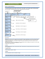
Exhaust air filter, article No: Q120101
Supply air filter, article No: Q120100
REC Indovent AB, Box 37, SE-431 21 Mölndal, Sweden | +46-31-675500 | www.rec-indovent.se
1
Air Handling Unit RT 250/400S-EC-RS
CONTENTS
Sid
Design & technical information
Product description
Casing
Filter, exhaust air
By‐pass damper
Fan, exhaust air
Fan, supply air
Heat exchanger
Filter, supply air
Inspection door
Adjustable feet
Condensate drain
Control panel
After‐heater
Functional diagram ‐ supply air control
Chiller / Cooling coil (optional)
Technical specification
Dimensions
3
3
3
3
3
3
3
3
3
3
3
3
3
4
4
5
5
Options
Setpoint adjustment Easy (TG-R4)
Remote panel ED-RU
Remote panel ED-RU-DOS
15
15
15
Maintenance & service
Cleaning
Changing filter
Cleaning fans
Cleaning the heat exchanger
Checking the condensate drain
Cleaning, air diffusers
Cleaning the duct system
Checking the outdoor air intake
Service
Disposal
17
17
17
17
17
18
18
18
18
18
Operation & control unit
Overview
6
Control unit main screen
The menu system
How to change values and settings
Menu screens, structure and contents
7
Main menu
Version
Language
Address
1. Temperature
8
Temperatures
ECO-adjustment
Control function
2. Mode
9-10
Fan control
Timer adjustments
Date, time and summer/wintertime
Activate timer
Time schedule
Holiday schedule
3. In/Outputs
11
Analog inputs status
Digital inputs status
Analog outputs status
Digital outputs status
Calibrate sensors
4. Manual/Auto
12
Supply air controller
Fans, by-pass damper, heat and chill
Digital outputs
Filter timer
5. Alarm
13
Alarm history
6. Load settings
14
7. Authorization
14
REC Indovent AB, Box 37, SE-431 21 Mölndal, Sweden | +46-31-675500 | www.rec-indovent.se
2
DESIGN & TECHNICAL INFORMATION
Ventilationsaggregat RT 250/400S-EC-RS
5. Supply air fan
The same type as exhaust air fan (see point 4)
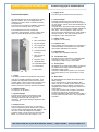
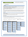
Product description
RT 250/400S-EC-RS is an air handling unit (AHU)
fitted in a cabinet. The unit is designed for the
ventilation of homes, offices, nurseries and other
small premises.
The Temovex unit should be installed in a heated
room, such as a scullery, laundry or similar.
6. Heat exchanger
The highly efficient Temovex counterflow heat
exchanger was first designed over 30 years ago by
our own people, and has since been developed to fit
today's needs.
It is made of thin aluminium sheets, and the supply
air and exhaust air sides are completely sealed from
each other. This is important in order to avoid
odours and other contaminants from old air seeping
through to fresh air. The heat exchanger has no
moving parts, which eliminates wear.
The standard Temovex unit consists of a
counterflow heat exchanger, 2 fans, 2 filters, afterheater, by-pass damper and a control system.
12
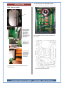
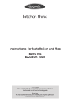
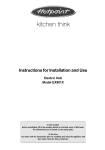
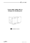
1. Door
7. Supply air filter
F7, bag (art. No. Q120100).
2. Filter, exhaust air
7
11
2
4
3. By-pass damper
8. Inspection door
When cleaning the heat exchager or controlling the
condensate drain, the Inspection door is opened.
(See chapter "Maintenance & service").
4. Fan, exhaust air
5
5. Fan, supply air
3
6. Counterflow heat
9. Adjustable feet
The cabinet has adjustable rubber feet.
exchanger
1
7. Filter, supply air
(behind 2.)
6
10. Condensate drain
The Temovex unit is fitted with a condensate drain
at the bottom of the unit, ¾". This should be
connected to a drain or fed to a floor drain.
8. Inspection door
9. Adjustable feet
10. Condensate drain
11. Control panel
All settings for fan speed, after-heating, by-pass etc.
are made via the control panel and the AHU's
integrated control system.
If you have added optional parts to your Temovex
AHU, these functions, too, are set via the control
panel.
11. Control panel
8
10
12. After-heater
9
1. Casing
The casing is made of hot galvanised sheet metal
with 30 mm insulation between the sheets. As a
standard, the side panels and the front are white
(powder paint). The front door has a magnetic strip
which keeps the door closed. The unit top has
sleeve connections where all ducts are connected.
12. After-heater
RT 250/400S-EC-RS is fitted with an electric afterheater, 0.9 kW.
As an optional extra, a reinforced electric afterheater, 1,8 kW, or a water coil (two different sizes)
for waterborne heating is offered. The heater is
integrated in the unit and settings are made via the
control panel.
In the case of a water coil, the water connections
are at the top of the unit, dimension DN12.
The RT 250/400S-EC-RS with water coil includes a
two-way valve and valve motor in the consignment
from REC..
2. Exhaust air filter
G3, bag (art. No. Q120101)
3. By-pass damper
The Temovex AHU has an automatic by-pass
damper which makes the air by-pass the heat
exchanger whenever heat recovery is not
necessary. The by-pass setting is adjusted on the
control panel.
4. Exhaust air fan
The low-energy fan is of EC type. It has a wide
working range and works at constant flow ("cruise
control"), which compensates for filter clogging. The
fan motor comes with integrated overheating
protection which cuts the power and stops the fan.
Reset: turn the fan motor off for approx. 1 min.
REC Indovent AB, Box 37, SE-431 21 Mölndal, Sweden | +46-31-675500 | www.rec-indovent.se
3
Air Handling Unit RT 250/400S-EC-RS
DESIGN & TECHNICAL NFORMATION
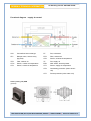
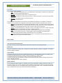
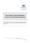
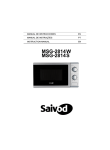
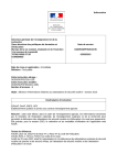
Functional diagram - supply air control
VVX
Counterflow heat exchanger
FF
Fan, exhaust air
ST1
Damper motor, heat recovery
FFR
Filter, exhaust air
(By-pass)
GT5
Sensor, exhaust air temperature
TFR
Filter, outdoor air
TF
Fan, supply air
GT11
Sensor, outdoor air temperature
EVB
After-heater, electricity/water
GT3
Sensor, extract air temperature
GT1
Sensor, supply air temperature
GT2
Overheating protection (when electric
coil)
GT7
Freeze protection (when water coil)
Chiller (cooling coil) EKB
(optional)
REC Indovent AB, Box 37, SE-431 21 Mölndal, Sweden | +46-31-675500 | www.rec-indovent.se
4
Air Handling Unit RT 250/400S-EC-RS
DESIGN & TECHNICAL NFORMATION
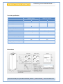
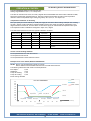
Tecnical specification
RT250
RT400
HW version
Water temp. 55/45°C
RT250
RT400
1034 W
1138 W
134 W
238 W
1150 W
1500 W
Electrical version
Rated output, unit
Rated output, standard heater
900 W
Rated output, reinforced heater
Rated output, fans
Voltage/Frequenzy input
Fuse
1800 W
2 x 67 W
2 x 119 W
2000 W
2800 W
2 x 67 W
2 x 119 W
230 V, 50 Hz
230 V, 50 Hz
10 A
10 A
Bag F7 / Bag G3
Bag F7 / Bag G3
100 kg
100 kg
Water connection
-
DN12
Fire classification
A15
A15
430x620x1900 mm
430x620x1900 mm
Duct connections
4 x Ø160 mm
4 x Ø160 mm
Condensate drain
¾”
Filter, supply air / exhaust air
Weight
Measurements (WxDxH)
¾”
-20 …. +50ºC
Storage Temperature Range
0 …. +50ºC
Operating Temperature
Dimensions
REC Indovent AB, Box 37, SE-431 21 Mölndal, Sweden | +46-31-675500 | www.rec-indovent.se
5
Air Handling Unit RT 250/400S-EC-RS
OPERATION & CONTROL
Overview
On the following pages you will find information about the basic functions that you yourself can adjust to fit your
requirements and wishes. The unit control system optimizes its function according to the settings you define.
Please note the following:
In the menus regarding heating and cooling, where you have the option of making changes, Auto Mode gives you
an optimized function. If you select a manual setting, On or Off, the manual setting overrules auto settings.
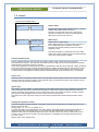
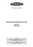
Control unit
Up
REC TEMOVEX
Mode: Normal
Status: Heating 100%
Temp. : 21.0 °C
↓
Down
Right
Left
OK
OK
C
Confirm
Show alarm
C
Delete
Flashing
There are one or more alarms that have not been acknowledged..
Steady
There are one or more acknowledged alarms left.
Flashing
You are in a menu where it is possible to change some parameters.
Steady
You are now in change position.
Alarm
Setting
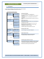
The menu system
The AHU's settings and status can be studied by scrolling the menu screens. Some parameters and settings can
be changed. Basic system configurations cannot be changed without authorized access code (technician level).
If no buttons are pressed for 25 minutes, the system will automatically revert to the control unit's Main screen.
When the access code has been used to log in, the system will automatically log out when 25 minutes have
passed.
How to change values and settings
The yellow LED is flashing in menus where adjustments can be made by the user (see page 6).
If you press OK, the changeable parameter will flash. Changes are made using the arrow buttons up or down.
Move between positions sideways using the arrow buttons right and left. When the desired value shows, confirm
with OK.
The cursor automatically indicates next variable that is possible to adjust in this menu.
REC Indovent AB, Box 37, SE-431 21 Mölndal, Sweden | +46-31-675500 | www.rec-indovent.se
6
Air Handling Unit RT 250/400S-EC-RS
OPERATION & CONTROL
Menu and structure
The manual shows the menus roughly the same way as they appear on the terminal. If jumps between different
menus are possible, these are shown in the manual. In some cases, more information about menus are shown
after each section. The walk through the menus starts with the main menu below.
Move sideways with the
arrow buttons right/left.
Main menu
REC TEMOVEX
Mode: Normal
Status: Heating
Temp. : 20.0 ºC
100%
Ô
~ €
Ó
►Temperature
Mode
In/Outputs
Manual/Auto
~ €
Ó
Temperature
►Mode
In/Outputs
Manual/Auto
~ €
Ó
Temperature
Mode
►In/Outputs
Manual/Auto
~ €
Mode
In/Outputs
►Manual/Auto
Alarm history
Ó
~ €
In/Outputs
Manual/Auto
►Alarm history
Load settings
Ó
~ €
Manual/Auto
Alarm history
►Load settings
Authorization
Ó
~€
Manual/Auto
Alarm history
Load settings
►Authorization
Ó
|
}
Version
Version:1.3-0-03
ID number:13261274
14:02:18 08:02
|
}
|
}
Choose language
English
Address:
PLA: 254
ELA: 30
|
}
Temperature, continue to page 8
|
}
Mode, continue to page 9
|
}
In/Outputs, continue to page 11
|
}
Manual/Auto, continue to page 12
|
}
Alarm history, continue to page 13
|
}
Load settings, continue to page 14
|
}
Move vertically with the
arrow buttons up/down.
The menu-tree continues
on page … in the
manual.
Authorization, continue to page
14
Main menu
Mode shows current fan mode. The unit can work in different modes, depending on for instance temperature and
commands given to the unit. Available modes are Stop, Low, Normal, Boost, Max, Kitchen mode, Stove mode,
Night cooling, Defrost, ECO, Fire, ECO2 and Safe mode. Further information can be found under the various
heading in this manual.
Status shows the current level of heating or cooling. Available modes are Heating xx%, By-pass xx% and Cooling
xx%. If they all show level 0%, the unit shows ------ 0%.
Temp shows current set temp.
Version
Shows current program version and the serial number of the electronics. Present date and time is shown and can
be changed here.
Language choice
Choose Swedish, English or Polish.
Address
Shows the address to the unit. Possible to change.
REC Indovent AB, Box 37, SE-431 21 Mölndal, Sweden | +46-31-675500 | www.rec-indovent.se
7
Air Handling Unit RT 250/400S-EC-RS
OPERATION & CONTROL
1. Temperature.
Temperature
The outdoor temperature is measured on incoming air close to the AHU. The temperature can differ a little from
the real outdoor temperature, depending on the duct length, insulation etc.
The supply air temperature is measured in the supply air duct, normally about one meter from the AHU. Supply air
is the fresh air that - after possible heating - is sent into the room.
The exhaust air temperature is measured close to the AHU. Exhaust air is the air that leaves the room and goes
back to the AHU, where the heat is recovered.
The extract air temperature is measured close to the AHU. Extract air leaves the AHU and is sent out from the
house.
The room temperature is measured with an external sensor, placed in an appropriate place in the flat/house.
The freeze protection temperature is only used with water heating and shows the temperature of the return water
from the heater. To prevent freezing of the water heater, the AHU will stop if the water temperature is too low.
ECO adjust.
ECO adjust. is only used with exhaust air control and room control, and gives a temperature range where heating
and cooling is disabled.
Example: ECO-adjust 2 degrees and a set temp at 20 degrees means heating and cooling will be disabled
between 18 and 22 degrees. ECO-adjust is activated when ECO is enabled.
Control function
What is shown in the temperature menu depends on the selected control function. There are four control functions
to choose between, depending on application: a) supply air control, b) cascade exhaust air control, c) cascade
room control and d) outdoor compensated supply air control.
For temperature settings and reading, choose the column that corresponds to your configuration.
a) Supply air control
b) Exhaust air control
c) Room control
d) Outdoor compensated supply air
control
Continued from Temperature, page 7
|
}
|
}
Supply air temp.
Actual : 25.1 ºC
Setpoint: 25.0 ºC
↓
~ €
|
Outdoor air temp.
Actual: 15.5 ºC
|
Outdoor air temp.
Actual: 15.5 ºC
|
|
|
↓
Freeze P. temp.
Actual: 8.5 ºC
↑
|
Supply air temp.
Actual: 25.1 ºC
Exhaust air temp.
Actual: 20.1 ºC
|
↓
*
Exhaust air temp.
Actual: 20.1 ºC
|
|
↓
|
↑
|
Extract air temp.
Actual: 11.5 ºC
|
|
Exhaust air temp.
Actual: 20.1 ºC
↑
~ €
|
Outdoor comp. setp.↑
10 ºC = 18 ºC
15 ºC = 12 ºC
Extract air temp.
Actual: 11.5 ºC
↑
~€
↑
↑
~ €
↓
|
↓
Freeze P. temp.
Actual: 8.5 ºC
|
Outdoor comp. setp.↑
-5
ºC = 23 ºC
0
ºC = 22 ºC
5
ºC = 20 ºC ↓
~ €
↑
~€
*
↑
↓
↓
~€
Freeze P. temp.
Actual: 8.5 ºC
Supply air temp.
Actual: 25.1 ºC
~€
↑
~€
↑
Outdoor comp. setp.
-20 ºC = 25 ºC
-15 ºC = 24 ºC
-10 ºC = 23 ºC ↓
↓
↓
~€
Extract air temp.
Actual: 11.5 ºC
|
~€
↑
|
}
~ €
↑
~€
↑
~€
↑
~ €
|
Supply air temp.
Actual: 25.1 ºC
OD temp.: 15.5 ºC ↑
Supply air temp.
Act.: 25.1 ºC Setp.->
Comp.SP: 12.0 ºC ↓
↓
↓
~ €
|
|
Outdoor air temp.
Actual: 15.5 ºC
~€
↑
↓
Extract air temp.
Actual: 11.5 ºC
↑
↓
~ €
|
}
Room temp.
↑
Actual : 20.1 ºC
Setpoint: 20.0 ºC
ECO adjust.: 2
ºC
↓
~€
~ €
↑
↓
Exhaust air temp.
Actual: 20.1 ºC
|
}
Exhaust air temp. ↑
Actual : 20.1 ºC
Setpoint: 20.0 ºC
ECO adjust.: 2
ºC↓
Freeze P. temp.
Actual: 8.5 ºC
↑
*
*
* The menu Freeze P temp. is only shown if water heater is configured.
REC Indovent AB, Box 37, SE-431 21 Mölndal, Sweden | +46-31-675500 | www.rec-indovent.se
8
Air Handling Unit RT 250/400S-EC-RS
OPERATION & CONTROL
2. Operation mode
In the mode menu, the operation mode of the fans can be changed. Date and time can be set and the timer can
be configured.
Continued from Mode, page 7
|
}
|
}
►Fan control
Timer
Fan control
Mode: Auto
~ €
|
Fan control
►Timer
|
}
Time:
08:59
Date:
14:02:25
Weekday: Tuesday
Summer/winter time ↓
|
Activate timer
↑
No
The timer controls:
ECO
~ €
|
}
|
}
Adjust clock
Automatically for
Summer time: Yes
►Schedule
Holiday schedule
~€
|
|
}
Holiday (mm:dd)
1: 01-01 - 01-01
2: 01-01 - 01-01
3: 01-01 - 01-01
|
Holiday (mm:dd)
4: 01-01 - 01-01
5 01-01 - 01-01
6: 01-01 - 01-01
|
Holiday (mm:dd)
7: 01-01 - 01-01
8 01-01 - 01-01
9: 01-01 - 01-01
Schedule
►Holiday schedule
|
}
↓
~€
|
}
|
}
Monday:
Per 1: 08:00- 17:00
Per 2: 00:00- 00:00
↓
|
}
Monday->Friday:
Per 1: 08:00- 17:00
Per 2: 00:00- 00:00
|
}
Saturday->Holiday:
Per 1: 00:00- 00:00
Per 2: 00:00- 00:00
~ €
↑
|
Tuesday:
↑
Per 1: 08:00- 17:00
Per 2: 00:00- 00:00
↓
|
Wednesday:
↑
Per 1: 08:00- 17:00
Per 2: 00:00- 00:00
↓
~€
~ €
|
Holiday (mm:dd)
↑
10: 01-01 - 01-01
11: 01-01 - 01-01
12: 01-01 - 01-01 ↓
|
Thursday:
↑
Per 1: 08:00- 17:00
Per 2: 00:00- 00:00
↓
~€
~ €
|
Holiday (mm:dd)
↑
13: 01-01 - 01-01
14: 01-01 - 01-01
15: 01-01 - 01-01 ↓
|
Friday:
↑
Per 1: 08:00- 17:00
Per 2: 00:00- 00:00
↓
~€
~ €
|
Holiday (mm:dd)
↑
16: 01-01 - 01-01
17: 01-01 - 01-01
18: 01-01 - 01-01 ↓
|
Saturday:
↑
Per 1: 08:00- 17:00
Per 2: 00:00- 00:00
↓
~€
~ €
|
Holiday (mm:dd)
↑
19: 01-01 - 01-01
20: 01-01 - 01-01
21: 01-01 - 01-01 ↓
|
Sunday:
↑
Per 1: 00:00- 00:00
Per 2: 00:00- 00:00
↓
~€
~ €
|
Holiday (mm:dd)
↑
22: 01-01 - 01-01
23: 01-01 - 01-01
24: 01-01 - 01-01
Public holiday:
↑
Per 1: 08:00- 17:00
Per 2: 00:00- 00:00
↓
~€
~ €
↑
↓
|
REC Indovent AB, Box 37, SE-431 21 Mölndal, Sweden | +46-31-675500 | www.rec-indovent.se
9
Air Handling Unit RT 250/400S-EC-RS
OPERATION & CONTROL
Fan control
Five modes are always available:
·
Auto: gives you an optimized function. The temperature is automatically controlled in accordance with
the unit's internal and optimized algorithms.
·
Min. flow: The system is forced to use a set minimum air flow.
·
Boost flow: The system is forced to boost the air flow. Useful for example if you need to air the building
very fast.
·
Max. flow: The system works at set maximum air flow.
·
Off: All fans are switched off.
Four other modes are available if those functions are installed and configured. (It is possible to choose these
modes even if the function is not configured, but the system will return to earlier choice after a few seconds.
·
Stove: This mode should be used when the stove/fireplace is used. The supply air fan works at a higher
speed than the exhaust air fan, to compensate for the air the stove extracts. The cooling is disabled for a
while after the stove/fireplace has been used, in order to retain the good stove heat.
·
Kitchen: Use this mode when the cooker fan is running. The supply air fan works at a higher speed than
the exhaust air fan, to compensate for the air the cooker fan extracts.
·
ECO: Suitable to use when no one is at home. The fans switch to minimum flow, but gradually
increase to normal flow when there is need for higher or lower temperature. ECO-adjust gives a
temperature range around the setpoint and neither heat nor cool is enabled.
·
Fire: To be used above all when testing the fire function. The supply air fan stops at the same time as
the exhaust air fan works at its maximum speed.
Timer settings
The clock and summer/winter time
The clock can be set and the change between summer and winter time can be made automatic.
Enable timer
The timer is enabled upon delivery and connected to the function Min flow. If the timer is disabled, so are preset
times and holiday schedules.
Time schedule
Two periods a day may be set. Note! To enable the timer from, for example Monday 20:00 until Tuesday 06:00
the settings should be Monday Per 2: 20:00 – 24:00 and Tuesday Per 1: 00:00 – 06:00.
To repeat the same time every day of the week, use the function Monday Ú Friday.
If you want the same time on Saturdays, Sundays and all holidays (specified in holiday settings), use the macro
function Saturday Ú Holiday.
There is a separate menu for holiday schedules.
Holiday schedule
Up to 24 separate holiday periods for a complete year may be programmed. A holiday period may consist of a
succession of days, from 1 to 365. The date is written: MM:DD. (It is important to set the time period from 00:00
one day until 00:00 next day. For example holiday June 6 will be written 06:06 – 06:07.) If that particular day falls
during a holiday period, the system will use the schedule for “Holiday”.
REC Indovent AB, Box 37, SE-431 21 Mölndal, Sweden | +46-31-675500 | www.rec-indovent.se
10
Air Handling Unit RT 250/400S-EC-RS
OPERATION & CONTROL
3. In/Outputs
In this menu it is possible to check the status of every input and output.
It is also possible to calibrate the sensors in this menu.
Continued from In/outputs, page 7
|
}
►Analog inputs
Digital inputs
Analog outputs
Digital outputs
|
}
AI1
AI2
AI3
AI4
OB temp
SA temp
EA temp
EXT temp
10.0ºC
20.0ºC
21.3ºC
14.0ºC↓
~ €
~ €
|
Analog inputs
►Digital inputs
Analog outputs
Digital outputs
|
|
}
UAI1 Room t. 10.0ºC↑
UAI2 Freeze t. 12.0ºC
UAI3 TG-R4.
0.5 ºC
DI1 AHU On/Off :On
DI2 Not active :Off
DI3 Not active :Off
↓
~ €
|
~ €
DI4
DI5
DI6
DI7
SA fan :Ok
↑
EA fan :Ok
Not active :Off
Overheat p:Ok ↓
~ €
|
DI8 FilterAla:Ok
↑
Analog inputs status.
All current temperatures are displayed here.
The room temperature is only displayed if room control is
configured.
Freeze temperature is only displayed if water heater is
configured.
UAI3 displays the adjusted setpoint if TG-R4 is chosen as
option.
Digital inputs status.
”Not active” means that the input is not in use (nothing is
configured to the input).
“On” means 24V on the input and the function that is
configured to the input is active.
“Off” means 0V on the input and the function that is
configured to the input is not active.
The alarm inputs can have status Ok or Alarm.
Analog outputs status.
|
Analog inputs
Digital inputs
►Analog outputs
Digital outputs
|
}
AO1
AO2
AO3
AO4
SA fan:
5.0
EA fan:
5.0
Heater: 10.0
Chiller : 0.0
|
}
DO1
DO2
DO3
DO4
BP opening
BP closing
PWM heat
Sum alarms
V
V
V
V
Current voltage on the output is displayed.
~ €
|
Digital inputs
Analog outputs
►Digital outputs
Calibrate sensors
:On
:Off
:Off
:Off↓
~ €
~ €
|
Digital inputs
Analog outputs
Digital outputs
►Calibrate sensors
|
DO5 CP heater
DO6 KAVK
DO7 ULS
:Off↑
:Off
:On
|
}
AI1:
AI2:
AI3:
AI4:
0.0
0.0
0.0
0.0 ↓
|
UAI1: 24.7ºC K: 0.0↑
UAI2: NaN ºC K: 0.0
UAI3:
ºC K:
UAI4:
ºC K:
18.3ºC
24.6ºC
23.2ºC
13.3ºC
K:
K:
K:
K:
~€
Digital outputs status.
”On” means that the output is active and “Off”
consequently that the output is not active.
Calibrating the temperature sensors.
The sensors’ values may be adjusted up or down. (Set an
offset value). For example, the old common thermometer
could be synchronized with the AHU temp. State the
difference here and they will show the same.
REC Indovent AB, Box 37, SE-431 21 Mölndal, Sweden | +46-31-675500 | www.rec-indovent.se
11
Air Handling Unit RT 250/400S-EC-RS
OPERATION & CONTROL
4. Manual/Auto
Continued from Manual/Auto, page 7
|
}
SA controller
Auto
Man. output: 0
↓
~ €
|
Supply air fan
Auto
Man. output: 0
|
Exhaust air fan
Auto
Man. output: 0
↑
↓
~ €
↑
↓
~ €
|
Heater
Auto
Man. output:
Available menus are shown here. All functions cannot be configured at the
same time as there are not enough outputs available. Furthermore, some
functions are not needed in the application.
If an output is controlled manually, it means that the normal regulation is out
of order. Therefore, an alarm will be generated as soon an output is changed
to anything else than Auto.
↑
0
↓
~ €
|
In Manual/Auto it is possible to control a number of functions manually, which
is very useful during the start-up process and for troubleshooting.
PreHeat
Auto
Man. output:
↑
0
↓
Supply air controller
The output from the supply air controller may be adjusted manually between
0-100%. The output from the temperature controller will follow if it is in Auto
mode.
~ €
|
BP / By-pass damper↑
Auto
Man. output: 0
Pos.: 100% open
↓
~ €
|
Chiller
Auto
Man. output:
↑
↓
ULS/OD air damper
Auto
↑
↓
~ €
|
KAVK / Cond. boiler↑
Auto
↓
~ €
|
CP/Circ. pump
Heater: Auto
↑
↓
~ €
|
The output to the fans, heater, by-pass damper and cooling may be adjusted
manually between 0-100%. The actual position of the by-pass damper is
displayed in the menu.
0
~ €
|
Fans, By-pass damper, Heat and Cool.
CP/Circ. pump
Chiller: Auto
Digital outputs
All configured digital output signals, such as ULS, KAVK, CP etc, can be
assigned Auto, On or Off (or a similar word that indicates the two possible
levels of a digital signal).
Filter timer
The filter timer is administered here. The interval between the filter changes
may be set from 6 to 18 months. The menu displays how many months
remain before the filters must be changed. Do not forget to reset the timer
when the filters are changed (even if the filters are changed earlier than
expected).
↑
↓
~ €
|
Fire damper
Auto
↑
↓
~€
|
Filter timer
Interval: 12 mån
Remains: 10 mån
Set zero: No
↑
REC Indovent AB, Box 37, SE-431 21 Mölndal, Sweden | +46-31-675500 | www.rec-indovent.se
12
Air Handling Unit RT 250/400S-EC-RS
OPERATION & CONTROL
5. Alarm
All current alarms and the status can be seen by pressing the red button.
In this menu alarms can be acknowledged, blocked or unblocked (allow alarm).
There are 2 types of alarms: A and C alarms. A-alarms do not disappear until they have been fixed and
acknowledged. C-alarms are internal alarms and will disappear automatically as soon as the alarm reason has
disappeared.
Some faults cause immediate stop of the unit, as continued operation would be dangerous.
An acknowledged alarm that has not yet been dealt with remains on the menu as Acknowledged. It disappears
from the menu when the fault has been dealt with.
It is possible to block an alarm and continue to run the unit. Note! Do not do this unless you really know what you
are doing, since it could be dangerous and in worst case damage both unit and property.
Sensor error OD
Any menu
Back to earlier menu
|
28 Feb 15:20 Klass:A
↓
~ €
EL.heat. overheated
EL.heat. overheated↑
28 Feb 14:34 Klass:A
OK
►Acknowledge
Block
Alarm history
The last 21 alarms are displayed. You can see when the alarm went off, when it was acknowledged and/or
returned and so on. In this menu, it is not possible to acknowledge or block any alarms.
Continued from Alarm history, page 7
|
}
28 Feb 15:20
A
↑
EL.heat. overheated
Activated
↓
~ €
28 Feb 13:50
A
Sensor error OD
Acknowledge
|
↑
↓
List of alarms. (abbreviations – see page 43)
A-alarm
Sensor error OD temp
Sensor error SA temp
Sensor error EA temp
Sensor error EXT temp
Sensor error RM temp
Sensor error FRP temp
Freeze P alarm
Supply fan failure
Exhaust fan failure
El. heat. overheated
Filter alarm
Filter guard
Fire damper alarm
Fire alarm
C-alarm
SA controller man.
SA fan manual
EA fan manual
Heater manual
By-pass manual
Chiller manual
ULS (Outdoor air damper) manual
KAVK (Condensation boiler) manual
P1-heating manual
P1-cooling manual
Int. battery failure
REC Indovent AB, Box 37, SE-431 21 Mölndal, Sweden | +46-31-675500 | www.rec-indovent.se
13
Air Handling Unit RT 250/400S-EC-RS
OPERATION & CONTROL
6. Load settings
Continued from Load settings, page 7
|
}
Load saved
settings:
No
Earlier saved settings are loaded back to the DUC here. If nothing has been saved, the standard settings apply.
All settings except date and time will be loaded.
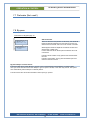
7. Authorization
Continued from Authorization, page 7
|
}
►Log in
|
}
Log in
State code: ****
Cur.level:None
This is where an authorized technician can log in to adjust the system and, if necessary, change parameters.
REC Indovent AB, Box 37, SE-431 21 Mölndal, Sweden | +46-31-675500 | www.rec-indovent.se
14
Air Handling Unit RT 250/400S-EC-RS
OPERATION & CONTROL
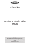
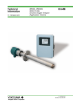
Options
Remote panel – Easy (art.no. Q100446)
Remote panel - Easy (TG-R4) has a temperature sensor and a set point knob.
The unit is used as room sensor with possibility to adjust the set point within
preprogrammed limits.
The normal set point is set on the display at the ventilation unit. This set point can later
be moved some degrees up or down on the Remote panel – Easy.
The adjusted value is displayed on the display at the ventilation unit.
Remote panel – Easy has analog transmission of data to the ventilation unit.
Remote panel - Easy
Remote panel – Without display (art.nr. Q100040)
Remote panel – Without display has a temperature sensor and a set point knob.
The unit is used as room sensor with possibility to adjust the set point within
preprogrammed limits.
Remote panel – Without display has the same functions as Remote panel – Easy, but
works with serial data (RS485) to the ventilation unit.
Remote panel – Without display
Remote panel – With display (art.nr. Q101299)
”Away” button
Setting buttons
Navigation button
Remote panel – With display is the most advanced remote
panel. It has a temperature sensor that could be used as room
sensor. This unit has a display and buttons that enables you to
see different temperatures and to set them. It is also possible
to change the fan speed and see a lot of other information. In
addition to this there is an “away” button included.
Fan speed
Kitchen/Stove
Remote panel – With display
Fan symbol
At home
Set point symbol
Temperature
Indoor temp. symbol,
outdoor temp. symbol
and house symbol
By-pass open
Display the temperature set point.
When no buttons have been pressed for 10 seconds, the set point is displayed and both the indoor temperature
symbol and the house symbol are lit.
Changing of temperature set point.
Press the navigation button once and the set point symbol starts blinking. It is now possible to change set point
with the setting buttons. The value is saved by pressing the navigation button, or if no button is pressed for 10
seconds.
REC Indovent AB, Box 37, SE-431 21 Mölndal, Sweden | +46-31-675500 | www.rec-indovent.se
15
Air Handling Unit RT 250/400S-EC-RS
OPERATION & CONTROL
Display actual temperature.
Press the navigation button once more (within 10 sec) and the set point symbol will be turned off. The indoor
temperature symbol will start blinking and the display shows the actual value. At this point, the setting buttons
have no function. When no buttons are pressed for 10 seconds, the display will again show the set point.
Display outdoor temperature.
Press the navigation button once more (within 10 sec) and the indoor temp. symbol will be turned off. The
outdoor temperature symbol will start blinking and the display shows the outdoor temperature. At this point, the
setting buttons have no function. When no buttons are pressed for 10 seconds, the display will again show the set
point.
Fan speed:
Press the navigation button once more (within 10 sec) and the fan symbol, the fan speed symbol as well as MAN
or AUTO will light up. The fan symbol starts blinking and the fan speed can be changed to desired position (min,
normal, boost or max) with the setting buttons. The positions correspond with the possible settings in menu
choice MODE on the main display. A change made on the remote panel will also be seen on the main display.
The symbol MAN tells that the unit works in a different mode than AUTO.
The unit may run at a fan speed between minimum and normal, or between normal and boost flow, due to
boosting or safe mode. The symbol fan speed shows actual fan mode as follow:
·
·
·
·
·
Fan speed zero
< normal mode
= normal mode
> normal mode but < = boost mode
= max mode
no box is lit
the box leftmost is lit
the two boxes leftmost are lit
the three boxes leftmost are lit
all boxes are lit
If the unit has been put in manual mode on the main display, nothing will happen to the fan speed if you try to
change it on the remote panel. The symbols in the menu MODE on both the remote panel and the main display
will change, but the fans’ speed will not change until you shift from manual mode to AUTO on the main display.
The new settings will be saved when the navigation button is pressed, or when no buttons are pressed for 10
seconds. The main display again shows the set point.
Kitchen/Stove.
The symbol Kitchen/Stove will light up when the unit is placed in stove mode or kitchen mode.
Away mode/ECO-mode.
By pressing the "away" button, the "at home" symbol will be turned off and the unit will change to ECO mode.
Turn off ECO mode by pressing once more..
The function requires that ECO is configured on the main display.
By-pass damper.
The By-pass symbol will light up when the by-pass is open > 0 %.
Cool.
COOL will light up if cooling is configured at the main display and the cooling-valve is open > 0 %.
Heat.
HEAT will light up if the regulator is calling > 0 % heat.
Alarm.
SERVICE will light up if there are unacknowledged alarms.
Off.
OFF will light up if the unit is turned off.
REC Indovent AB, Box 37, SE-431 21 Mölndal, Sweden | +46-31-675500 | www.rec-indovent.se
16
Air Handling Unit RT 250/400S-EC-RS
MAINTENANCE & SERVICE
·
Cleaning
For best possible performance and a long life, the
AHU should be kept clean. Please see instructions
below on how to clean fans and heat exchanger.
Switch on the power using the main switch.
!
NOTE! The fans must under no
circumstances be cleaned under running
water!
Changing filters
Cleaning the heat exchanger
There are two filters in this AHU: exhaust air filter
and supply air filter (fresh air).
Both filters should be changed at least once a year,
and more often if need be. Do not wash the filters,
but exchange them for new ones.
To buy new filters, please contact the local dealer in
your country or order from www.rec-indovent.se
·
·
·
·
·
·
!
NOTE! The Temovex AHU must be fitted
with the Temovex filters listed on page 1 of this
manual. If the unit operates without filters, the
performance will be affected
adversely and fans and heat
exchanger may be seriously
damaged.
!
(Ref. numbers - see page 6)
·
Cut off the power using the
main switch.
·
Open the unit door (1).
·
Remove Cover plate A (see
page 2).
·
Take hold of the filter (2) or of the
clamp between the bags. Push the front part
backwards, downwards.
·
The supply air filter (7) is behind the inner over
plate, behind the exhaust filter. Remove the
filter.
·
Clean accessible surfaces if necessary.
·
Fit the new filters in reverse order (the blue,
exhaust air filter, is fitted in the front).
·
Refit the access door.
·
Close the unit door.
·
Turn on the power.
·
·
·
!
·
·
·
The unit operates even if the filters are dirty, but the
performance would be less good; energy
consumption increases and heat recovery
decreases.
To turn off/aknowledge filter alarm, see Ch 5.
·
·
·
·
·
·
·
·
NOTE! The agent must be of a type which is
not aggressive to aluminium. Alkaline
detergents with caustic ammonia and alike
must never be used, since they have a
corrosive action on aluminium, i.e. ruin the heat
exchanger.
Refit the red plug (10) (On the same side of the
unit as the filters).
Refit the inspection door (8).
Refit the fans in reverse order (4, 5)
NOTE! Make sure the fan motors are not/do
not get wet when restarting the unit. If wet, this
could be fatal!
Refit the covers.
Close the unit door.
Turn on the power using the main switch.
Checking the condensate drain
·
·
·
Cleaning the fans
·
Cut off the power using the main switch.
Open the unit door (1).
Remove both covers (4 and 5) and remove
both fans (see above).
Open the inspection door (8)
Remove the red plug at the
bottom of the unit, the condensate
drain (10)
Flush the heat exchanger with hot
water.
NOTE! If the unit is fitted with a condensate
evaporator unit (KAVK), a wet vac should be
used to deal with the rinse water.
A degreasing agent may be required if the heat
exchanger is very dirty.
Cut off the power using the
main switch.
Open the unit door (1).
Remove both covers (4 and 5)
Clean one fan at a time.
Undo the fan's electric plug and
pull out the fan.
Clean the impeller using a brush
or compressed air.
Refit the fans in reverse order.
Refit the covers.
Close the unit door.
·
·
·
Open the unit door (1).
Open the access door (8) at the bottom of the
cabinet.
Make sure the drain is not
blocked. This can be done
by pouring some water into
the bottom of the unit.
NOTE! On the side which does not have a red
plug.
If the drain is jammed, try to remove the
obstruction. If need be, call a plumber.
Refit the access door.
Close the unit door.
REC Indovent AB, Box 37, SE-431 21 Mölndal, Sweden | +46-31-675500 | www.rec-indovent.se
17
Air Handling Unit RT 250/400S-EC-RS
MAINTENANCE & SERVICE
Cleaning the air diffusers
Checking the outdoor air intake
The building's air diffusers must be
cleaned regularly in order to maintain
correct ventilation. Use a dry cloth
and/or a small brush to reach inside the
opening of the diffuser. It can also be
taken down if that makes cleaning
easier. Use a duster or a dry cloth to
remove possible dirt marks in the ceiling
around the device.
NOTE! The air diffuser's setting must not be
changed. If taken down, each diffuser must be
returned to its original place.
Once a year the outdoor air intake should be
checked. Make sure it is not clogged by for
example leaves, snow or ice.
Service
Service and repairs, beyond normal maintenance,
should be carried out by professionals in the
ventilation field, or - if electricity is involved - by an
authorized electrician.
!
Cleaning the duct system
The exhaust air ducts - and sometimes the supply
air ducts as well - may need cleaning at long
intervals. Dust and dirt will deteriorate the capacity
of the AHU if not removed.
Authorized
ventilation
cleaners should
carry out the
cleaning.
However, you
yourself can
easily clean the
part of the duct
which is close to
the air diffusers.
Take down the diffuser. Use a vacuum cleaner or
duster to clean the inner part of the duct as far as
you can reach. Refit the diffuser, making sure the
setting is not changed.
!
!
!
The electric panel must not be opened by
other than authorized specialist.
The plates covering the fans must not be
removed when the AHU is running, as there is
a risk of contact with moving parts. Make sure
the electricity has been cut off (unplugged or
fuse removed).
Interferance with the AHU system may affect
the warranty terms.
Use original spare parts only.
Disposal
Prevent accidents when the AHU is disposed of.
Remove the cable from the wall socket and cut it as
close to the unit as possible. Store and transport
the waste unit lying down.
Please leave the unit to be recycled where such
facilities exist. Check with your local authority for
recycling advice..
List of abbreviations
AHU
BP
Comp.
CP
DUC
EA
El.heat.
EXT
FRP
h
Int.
KAVK
mm:dd
OD
P
per
pos.
RM
s
Setp.
SA
Temp.
ULS
air handling unit
by-pass damper
compensate(d)
circulation pump
controller
exhaust air
electric heating
extract air
freeze protection
hour
Internal
condensation boiler
month:day
outdoor
protection
period
position
room
second
setpoint
supply air
temperature
outdoor air damper
DATE is shown in the format YY-MM-DD.
TIME is shown in 24-hour format.
REC Indovent AB, Box 37, SE-431 21 Mölndal, Sweden | +46-31-675500 | www.rec-indovent.se
18
Notes:
19
REC Indovent AB reserves the right to make alterations to specification and construction without prior notification.
REC Indovent AB
Box 37, SE-431 21 Mölndal, Sweden
Besöksadress: Kärragatan 2
www.rec-indovent.se
Certified acc. to ISO 9001/14001
20
REC 15-06-11
Tel: +46 31 67 55 00
Fax: +46 31 87 58 45
Air Handling Unit RT 250/400S-EC-RS
Technician manual
INSTALLATION
OPERATION & CONTROL
Exhaust air filter, article No: Q120101
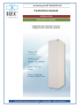
Supply air filter, article No: Q120100
REC Indovent AB, Box 37, 431 21 Mölndal | tel.031-675500 | www.rec-indovent.se
1
Air Handling Unit RT 250/400S-EC-RS
CONTENTS
Page
Installation
Safety
Receipt of goods
Installation - how
Installation - where
Condensate drain
Connecting ducts
Outdoor air, extract air
Mounting the duct system
Silencers
Temperature sensors - location
Insulation
Duct cover for AHU top
Air diffusers
Transmitted air between rooms
Stove/fireplace
Kitchen flue
Power connection
DUC - how to remove
Connecting the AHU, wiring diagram
Description of terminal blocks
Connecting options
Connecting Remote panel –
Without/With display
Connecting Remote panel –
Easy (TG-R4)
3
3
3
3
3
3
3
3
3
4
4
4
4
4
4
4
4
5
6
7
8
7.6 Heater
16
Electric heat
Water heat
Freeze protection control
Setting freeze protection
7.7 Preheater (not used)
17
7.8 By-pass
Defrost function
By-pass dampers cycle time
7.9 Cooling recovery
17
Activating and configuration
How it works
7.10 Night cooling
19
Activating night cooling
Conditions night cooling
Fan value for night cooling
How it works
7.11 Timer
20
7.12 KAVK (condensation boiler)
20
7.13 Fire function
21
Fire input
Fire damper function
Exercising fire damper
7.14 I/O configuration
22
Digital inputs
Timer
Connecting timer to wished function
Timer configuration
Priority
Configuring fan type
Stove mode
Configuring stove timer
Digital outputs
Inverting digital output
Analog outputs
7.15 Modbus
24
Parameter settings modbus
7.16 Save settings
24
Save current settings
Operation and control
7. Configuration
7.1 Control function
Control functions
Cascade control
Set point adjust
Several room sensors
7.2 Temperature control
Controllers function
Setting the controller’s
What is P and I?
7.3 PID output
7.4 Fan speeds
Setting fan speeds
Fan speed night cooling
Fan delay
7.5 ECO/ECO2
ECO-mode
ECO2-mode
ECO adjusting
Safe mode
Activate ECO2 cooling
Temp diff.
Temp diff for increase to boost
Screen view at boosting and ECO
Fan curve at ECO/ECO2
9
11
12
13
13
14
REC Indovent AB, Box 37, 431 21 Mölndal | tel.031-675500 | www.rec-indovent.se
2
Air Handling Unit RT 250/400S-EC-RS
INSTALLATION
Safety
!
The unit should be installed in such a way that it is
easy to access for maintenance and inspection.
Make sure the front door can be fully opened.
The AHU should be placed in such a way that water
cannot splash over it. As an option, the unit can be
equipped with protection that enables the
installation to comply with IP class X5.
Read this user's guide carefully before installing the
Air Handling Unit (abbreviated AHU), particularly
those parts marked with the above safety sign.
If you use and care for your AHU in a correct way, it
will perform in the best possible way for a long time.
Condensate drain
The AHU creates an indoor climate that is very
good, at the same time as energy is saved due to
efficient heat recovery.
The Temovex unit is fitted with a condensate drain
at the bottom of the unit, ¾". This should be
connected to a drain or fed to a floor drain. Make
sure the drain pipe is lowered well down in the floor
drain, or there might be a
cold draft. There is no
need for a water seal.
NOTE! The condensate
drain has to be connected
when the unit is installed.
If the unit is fitted with the optional condensation
boiler (KAVK), no external connection is required. If
the unit has a condensation boiler (KAVK) and/or if
the unit is installed on a wooden floor or other floor
material sensitive to damp, the AHU should be
placed on a water resistant mat (like the ones you
use under a dishwasher) to avoid damages caused
by possible leakage or condensation.
NOTE! This user's guide should be stored together
with the AHU, and should be passed on to possible
new owners.
Receipt of goods
Check the following before you sign the delivery
note:
·
the number of cartons should conform to the
delivery note/packing list
·
there should be no visible transport damages.
The AHU should be stored indoors.
! If possible, store the AHU laying down before
installation, in order to avoid it tipping over. This is
particularly important if there are children around.
Connecting ducts
Ducts and duct details should be made from an ageresistant material, and should be easy to clean
inside. A flexible duct connector can be used where
a short connection between for example roof hood
and duct system is needed.
Tumble dryers and drying cabinets must not be
connected directly to the duct system.
Installation – how
Work carried out by laymen may impair the
performance of the AHU and cause injury or
damage to persons or property. If the unit is
installed incorrectly, it will not be possible to achieve
the desirable benefits, such as satisfactory air
quality and maximum energy savings.
Outdoor air, extract air
The AHU is heavy. Edges and corners, which you
would not normally come into contact with, may be
sharp. Therefore, we suggest you wear gloves
when moving the unit.
The outdoor air intake, fitted with an external wall
grille, is best positioned on the north or east wall of
the building, slightly above ground level in order to
avoid dirt from the ground. The outdoor air intake
should be placed at a distance from kitchen flues,
exhausts from central vacuum clearners, etc.
!
Keep an eye on children! Before the unit has
been installed, it may easily tip over if abnormally
loaded.
Extract air should be discharged above roof level via
a roof hood. .
Installation – where
The unit can be installed in for example a scullery,
laundry or similar. Recommended minimum
temperature in the room is +12°C. At lower
temperature, heat loss and more condensate water
could be a problem.
Mounting the duct system
Ducts and duct details are fitted in accordance with
the instructions given by the duct supplier, normally
using 3 pop rivets or special assembly screws at
each joint. If duct details with rubber seals are used,
no additional joint sealing is required.
Place the unit upright on a flat and solid foundation.
In order to avoid structure-borne sounds, there
should be a gap of at least 10 mm between unit and
wall. We also recommend that walls to adjacent
rooms are soundproofed. These precautions should
be taken although the Temovex AHU is considered
very silent. The unit has adjustable rubber feet and
well balanced fans, to avoid vibration.
Silencers
Silencers dimensioned for the installation should be
fitted both for the supply air and exhaust air, either
directly onto the Temovex unit, or to the duct system
as close to the unit as possible. Under certain
conditions, silencers on the outdoor air duct as well
as extract air duct may be necessary.
REC Indovent AB, Box 37, 431 21 Mölndal | tel.031-675500 | www.rec-indovent.se
3
Air Handling Unit RT 250/400S-EC-RS
INSTALLATION
Temperature sensors - location
screw-heads in the
"key" holes. Fix the
cover onto the unit
by sliding it
backwards some 5
mm (see picture).
If the duct cover is
mounted onto an
existing
unit, the
pop rivets at the unit top have to be
replaced by screws.
Sensors for outdoor air, exhaust air and extract air
are already mounted in the AHU's respective air
ducts. They are also electrically connected to the
control system.
Should the unit be equipped with an after-heater,
the sensor for freeze protection is mounted and
connected.
The sensor for supply air is just electrically
connected upon delivery. It should be placed in the
supply air duct, at least 0,6 m from the heater to
avoid direct heat radiation, and after the first bend if
possible, where the temperature is more
homogeneous.
NOTE! Seal the lead-through carefully.
3.
If a room sensor is used, it should be placed approx.
1,8 m above floor level in the living room,
prefereably on an inner wall.
Whenever you need access to the
upper part of the Temovex unit, the
duct cover is lifted off in one piece
(point 2 above, but reverse order)
Air diffusers
Supply air diffusers are normally installed in rooms
where people spend much time, such as bedrooms
and living room.
Exhaust air diffusers are normally installed in "damp
and smelly" rooms, for example bathroom, laundry
etc.
Both supply and exhaust air valves can be mounted
on the wall or in the ceiling. They should be placed
where they can easily be demounted for cleaning,
service or inspection of the duct system.
Insulation
Outdoor air and extract air ducts in heated spaces
must be insulated against condensation along their
entire length, using an insulation sleeve with
minimum 30 mm insulation. The diffusion barriers
are sealed using ventilation tape.
Supply air and exhaust air ducts in warm rooms do
not need to be insulated against condensation,
however, heat insulation may be appropriate. This
should be decided in each individual case.
Supply air and exhaust air ducts located in cold or
unheated rooms should be insulated against frost.
If blanket insulation is used, 2 layers with
overlapping joints should be achieved, with a
minimum insulating thickness of 120 mm.
Transmitted air between rooms
To facilitate the circulation of air in the home, supply
air from rooms with such valves must be given the
chance to move to rooms with exhaust air valves.
Use doors with an air transfer slit, or doors without
door sill (minimum 70 cm 2 free area/exhaust air
valve).
Alternatively, wall mounted transfer air grilles can be
used.
If loose-fill insulation is being laid, the layer covering
the ducts must be at least 150 mm.
Duct cover for AHU top
Stove/fireplace
The lacquered, 2-piece cover hides the ducts at the
top of the Temovex unit. The cover is telescopic and
will fit ceiling heights between 2,30 - 2,70 m. We
recommend a gap of 5 mm between ceiling and
duct cover to avoid any transfer of vibrations.
1.
2.
Most modern stoves have a separate outdoor air
connection which provides combustion air to the
stove. If this is not available/possible, a separate
outdoor air device should be mounted. The stove
consumes some 150-300 m 3/h.
To facilitate the lighting of fires (to start with, the
stove door should be left ajar) an option is to
provide the Temovex AHU with a "stove" button.
Measure the
distance from the
top of the unit
(without duct
cover) to the
ceiling. Assemble
the two pieces on
a flat surface/floor,
and ensure that
the height will
allow a gap of
approx. 5 mm to
the ceiling. Use
the enclosed 4 self-tapping screws to make the
holes in the upper (smaller) cover plate. Use
the 4 white screws to join the two cover plates.
Kitchen flue
The cooker fan is fitted with a separate fireproof
spiral duct. The extract air is fed out via a roof
hood. Use an approved duct and 2 speed clamps to
connect the cooker hood/kitchen fan to the kitchen
flue.
Power connection
The AHU is provided with a grounded plug.
Connect the plug to an earthed 1-phase socket
(230 VAC / 10 A).
Connection at the top of the unit.
Put the duct cover on top of the unit, placing the
REC Indovent AB, Box 37, 431 21 Mölndal | tel.031-675500 | www.rec-indovent.se
4
Air Handling Unit RT 250/400S-EC-RS
INSTALLATION
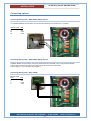
DUC – how to remove
DUC
Remove the DUC
from the PCB by
squeezing each
top of the four
spacers with a
pair of pliers.
Squeeze one at a
time and ease the
DUC out at the
same time.
After the installation of functions is done, re-fit the DUC in
reverse order.
The DUC is now
attached to the
board by 2 ribbon
cables only.
The spring locks
on the plugs of
the DUC's ribbon
cables make it
easy to loosen
them from the
circuit board.
The bottom card can now be reached and set up with
required functions.
The printed circuit board screen print.
REC Indovent AB, Box 37, 431 21 Mölndal | tel.031-675500 | www.rec-indovent.se
5
Air Handling Unit RT 250/400S-EC-RS
INSTALLATION
Connecting the AHU
wiring diagram
REC Indovent AB, Box 37, 431 21 Mölndal | tel.031-675500 | www.rec-indovent.se
6
Air Handling Unit RT 250/400S-EC-RS
INSTALLATION
Description of terminal blocks
Fans (J13 and J14)
Terminals for the fans. These are already
connected upon delivery.
General
Joining of circuits is made on the bottom circuit
board. To access the circuit board, remove the DUC
(see previous page).
Texts on the circuit board show where to connect
what. All terminals have a Jxx No. and a small
triangle on pin 1.
When in the following text for example J26/1,2 is
stated, it means that the function should be
connected to terminal J26, pin 1 and 2.
Where appropriate, the signal is marked on the
board.
By-pass (J28)
Connection terminal for the by-pass damper.
Optional terminal for by-pass (J29)
Extra connection terminal for by-pass damper
(some AHU models)
Ext.1, Ext.2 and Ext.3 (terminals J23 to J25/1,2)
As an optional extra, you can choose to connect
three external switches that will change the speed of
the fans in accordance with the preset values.
Suitable air flows have been preset, but may be
altered by a qualified installer, using the control
panel.
To see which options are available, please turn to
chapter "Operation & control".
Room sensor (terminal J6/1,2)
If a room sensor is installed, this must be stated in
the AHU's configuration. This is done by a qualified
installer.
External cooling (terminal J8/1,2,3)
The AHU can be fitted with an external water chiller
(cooling coil), for example natural cooling from a
drilling hole. The chiller is controlled via an external
control valve (0-10 V).
Start/stop (terminal J26/1,2)
An external switch for "Start/stop" can be
connected. The switch makes the AHU stop
running, but does not make it powerless.
If this function is used, the jumper J34 should be
moved to mode OFF.
After-heating water (terminal J7/1,2,3)
The water heater is controlled via an external
control valve (0-10 V).
(The cable may already be connected upon
delivery)
Optional terminal for filter guard (J21)
For some of the larger AHU models only.
Relay outputs (terminals J19, J20)
The system has 4 identical relay outputs which can
be configured to various functions. The
configuration shown above is one example, and
others may be made.
To see which options are available, please turn to
chapter "Operation & control".
A condensation boiler (KAVK), if any, would be
installed at the factory.
Temperature sensors (terminal J9)
Temperature sensors (PT1000) for outdoor air,
supply air, exhaust air and extract air are already
connected upon delivery.
Freeze protection - After-heater (terminal J10/3,4)
In connection with water heating, a freeze protection
(temperature sensor) is fastened on the return water
pipe of the after-heater, in order to protect the afterheater from freezing,
Mains voltage (terminals J15, J16, J17)
230VAC, 50Hz
Modbus (J12)
Terminal for possible modbus communication.
Casing (terminal J18)
Ground connection of the casing.
ECO Remote (J100)
Terminal for connecting a remote control (optional)
with among other things alarm indication and a
switch for ECO mode.
NOTE! When using ECO Remote, DO6 must be
configured for Normal flow, DO7 for Sum alarms
Electric heating, voltage feed (terminal J5/2,3)
Pin 2 phase, pin 3 neutral (blue).
Electric heating, control signals (terminal J4)
REC Indovent AB, Box 37, 431 21 Mölndal | tel.031-675500 | www.rec-indovent.se
7
Air Handling Unit RT 250/400S-EC-RS
INSTALLATION
Connecting options
Connecting Remote panel – Without/With display at port 1
If not addition Modbus communication, the remote panel should be connected to port 1 as below.
Remote panel
10
11
42
43
PCB
J8/1
J8/3
J12/3
J12/4
Connecting Remote panel – Without/With display at port 2
If addition Modbus communication, the remote panel should be connected to port 2. (No picture available).
The connection shall be close to the DUC signal A (42) and B (43) (not at the PCB).
Power supply (10, 11) in the same way as if port 1.
Connecting Remote panel – Easy (TG-R4)
Remote panel
Easy
1
2
3
4
PCB
J6/1
J6/2
J10/3
J10/4
REC Indovent AB, Box 37, 431 21 Mölndal | tel.031-675500 | www.rec-indovent.se
8
Air Handling Unit RT 250/400S-EC-RS
OPERATION & CONTROL
For introductory information se User manual!
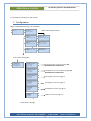
7. Configuration
Begin at Authorization and log on as Technician.
|
}
|
}
►Log in
State code 2222 (Technician)
Log in
State code: ****
Cur.level:None
|
}
►Log in
Log out
Change access code
~ €
|
Log in
►Log out
Change access code
|
Log in
Log out
►Change access code
~€
|
}
Log in
State code: ****
Cur.level:Technician
|
}
Want to log out?
No
Level: Technician
|
}
Change code for
Level: Technician
New code: ****
Then choose configuration
|
}
Alarm history
Load settings
►Configuration
Authorization
Ó
|
}
►Control function
Temperature control
PID output
Fan speeds
~ €
|
Control function
►Temperature control
PID output
Fan speeds
~ €
|
Control function
Temperature control
►PID output
Fan speeds
|
Temperature control
PID output
►Fan speeds
ECO/ECO2
|
PID output
Fan speeds
►ECO/ECO2
Heater
|
Fan speeds
ECO/ECO2
►Heater
PreHeat
~ €
~ €
~€
|
}
Control function, continue to page Fel!
|
}
Temperature, control continue to page Fel!
|
}
PID output, continue to page 13
|
}
Fan speed, continue to page 13
|
}
ECO/ECO2, continue to page 14
|
}
Heater, continue to page 16
Bokmärket är inte definierat.
Bokmärket är inte definierat.
~ €
Continues on next page.
REC Indovent AB, Box 37, 431 21 Mölndal | tel.031-675500 | www.rec-indovent.se
9
Air Handling Unit RT 250/400S-EC-RS
OPERATION & CONTROL
Continued from previous page.
~€
|
ECO/ECO2
Heater
►PreHeat
By-pass
|
Heater
PreHeat
►By-pass
Cold air recovery
~€
~€
|
PreHeat
By-pass
►Cold air recovery
Night cooling
|
By-pass
Cold air recovery
►Night cooling
Timer
|
Cold air recovery
Night cooling
►Timer
KAVK/Condens.boiler
|
Night cooling
Timer
►KAVK/Condens.boiler
Fire function
|
Timer
KAVK/Condens.boiler
►Fire function
I/O configuration
|
KAVK/Condens.boiler
Fire function
►I/O configuration
Modbus
|
Fire function
I/O configuration
►Modbus
Save settings
|
Fire function
I/O configuration
Modbus
►Save settings
~€
~ €
~€
~€
~€
~ €
~ €
|
}
Preheat, continue to page 17
|
}
By-pass, continue to page 17
|
}
Cold air recovery, continue to page 18
|
}
Night cooling, continue to page 19
|
}
Timer, continue to page 20
|
}
KAVK, continue to page 20
|
}
Fire function, continue to page 21
|
}
I/O configuration, continue to page 22
|
}
Modbus, continue to page 24
|
}
Save settings, continue to page 24
REC Indovent AB, Box 37, 431 21 Mölndal | tel.031-675500 | www.rec-indovent.se
10
Air Handling Unit RT 250/400S-EC-RS
OPERATION & CONTROL
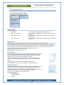
7.1 Control function
Continued from Control function page 9
|
}
Control function
SA control
↓
|
}
When cascade control
max/min SA setpoint
Max: 52.0 ºC
Min: 15.0 ºC
~€
|
Setpoint adjust.
↑
Min:-3.0 Max: 3.0 ºC
TG-R4: 0.0 ºC
Ext display: 0.0 ºC↓
~€
|
Roomsensor:
Only analog input
↑
Control functions
Selectable features:
·
SA control
·
ODT comp. SA control
·
Casc. Room control
·
Casc. EA control
The temperature is regulated by the SA sensor only.
The temperature is regulated as a function of the SA sensor and
OD sensor.
The temperature is regulated as a function of the room sensor
and SA sensor.
The temperature is regulated as a function of the EA sensor and
SA sensor.
Cascade control
This function is only active when cascade room control and cascade exhaust air control is used.
The room’s desired set point is set on the room sensor if room control and on the EA sensor if EA control. The
system calculates a new supply air (SA) set point based on the control error. In the extreme case (if large control
error) this could be very high (or low), which could generate much to cold or hot supply air, which could feel
uncomfortable. It is possible to limit the SA set point both up and down.
Setting range for both min and max is 0-150ºC.
Default settings are max 52ºC, min 15 ºC.
Set point adjust
The menu "Set point adjust" is used together with room sensor with set point
adjust included, like Remote panel – Easy (TG-R4) or Remote panel – Without
display. State the range for the set point adjust in this menu.
With the knob in mid position (0 adjust), use the set point in the main display.
The function “Set point adjust” is only working if it has been activated by the
factory.
Settable range for min and max is ±10 degrees. Default is ±3ºC.
Current adjustment can be seen in the display on the subsequent lines.
Remote panel - Easy
Several room sensors
If there is more than one room sensor and one of them is connected to the
analog input (a simple standard sensor or for example Remote panel – Easy
(TG-R4)) and the other one is a serial Remote panel, connected to port 1 or 2, it
is possible to choose from where the actual value should be taken.
This menu is only displayed if room control is used.
Selectable alternatives:
·
Only analog input
·
Only Remote panel
·
Average
Remote panel – Without display
REC Indovent AB, Box 37, 431 21 Mölndal | tel.031-675500 | www.rec-indovent.se
11
Air Handling Unit RT 250/400S-EC-RS
OPERATION & CONTROL
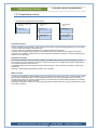
7.2 Temperature control
Continued from Temperature control page 9
If cascade EA
control
If SA control or ODT comp.
SA control.
|
}
SA control
P-band: 33.0 ºC
I-time: 100.0 sec
↓
|
}
I cascade Room
control
SA control
P-band: 33.0 ºC
I-time: 100.0 sec
↓
|
}
~€
|
EA control
P-band: 100.0 ºC
I-time: 300.0 sec
↓
SA control
P-band: 33.0 ºC
I-time: 100.0 sec
↓
~€
|
Room control
P-band: 100.0 ºC
I-time: 300.0 sec
↓
Controllers function
The SA controller is acting indirectly, which means that the output is rising with falling temperature. The controller
is a PI-controller with settable P-band and I-time.
In the first case, the temperature at the SA sensor will be constant at the set point.
In case 2 and 3,the supply air temperature is controlled as a part of a cascade control, together with the EA
controller/room controller. A difference in the room temperature relatively the set point, moves the operating point
until the error is eliminated.
Setting the controllers
The control parameters could be adjusted if needed. The default settings are 33 and 100 respectively, which in
most cases is ok. (It is the same SA controller in all three cases above. An adjustments will follow automatically if
one changes to another control function.)
The default setting of the EA controller and room controller (which in fact is the same controller) is 100 and 300
respectively.
Warning! A faulty setting could make the system work very badly.
What is P and I?
P-band is the temperature change needed to move the actuator from closed to fully open. A small P-band (= large
gain) causes an unstable system. A small temperature-change on the sensor generates maximum heat and
provides large overshoots. A large P-band (low gain) on the other hand provides smaller overshoots, but will take
longer before the correct value is reached.
Including an integrator (I-value) in the control loop will provides smaller overshoots. The gain decreases the closer
one comes to set point.
REC Indovent AB, Box 37, 431 21 Mölndal | tel.031-675500 | www.rec-indovent.se
12
Air Handling Unit RT 250/400S-EC-RS
OPERATION & CONTROL
7.3 PID output
Continued from PID output page 9
|
}
PID output:
Heating : 0
By-pass : 0
Cooling : 0
↓
%
%
%
Here the output from the SA controller is displayed, divided between the three outputs cooling, by-pass and
heating.
The output from the SA controller 0-100% is divided between the outputs as follow.
Controller output
(PID-output)
0 – 32%
32 – 64%
64 - 66%
66 - 100%
Cooling
By-pass
Heating
100 – 0%
0%
0%
0%
100%
100 – 0%
0%
0%
0%
0%
0%
0 - 100%
7.4 Fan speeds
Continued from Fan speeds page 9
Setting the fan speeds
|
►Supply air fan
Exhaust air fan
|
}
Min
Normal
Boost
Kitchen
|
Stove
= 80
Night cool = 50
Max
= 100
Fire
= 0
↓
=
=
=
=
20
50
80
80
%
%
%
%
↓
~ €
~ €
|
Supply air fan
►Exhaust air fan
% ↑
%
%
%
~ €
|
Delay SA fan
↑
Start: 0
sec
Stop: 60
sec
Ramp time V/s: 1.00
|
}
Min
Normal
Boost
Kitchen
=
=
=
=
20
50
80
20
%
%
%
%
In this menu the fan speed for different modes is set (in
% of max speed). By changing the %-value for each fan,
the system can be adjusted to get the correct flowbalance. The menu to the left, shows the default values.
Fan speed night cooling
The value for night cooling is, on delivery, the same as
normal mode.
If the value for normal mode is changed, the value for
night cooling will be changed too, unless the value for
night cooling is actively set to something else.
To get them synchronized again, set the night cooling
value at the same value as normal mode.
↓
~€
|
Stove
= 20
Night cool = 50
Max
= 100
Fire
= 0
↓
% ↑
%
%
%
|
Delay EA fan
↑
Start: 0
sec
Stop: 0
sec
Ramp time V/s: 1.00
~€
Fan delay
It is also possible to set a start and stop delay for each
fan, and a ramp time.
Settable values for start and stop is 0-3600 sec.
Settable values for the ramp time is 0-100V/sec.
REC Indovent AB, Box 37, 431 21 Mölndal | tel.031-675500 | www.rec-indovent.se
13
Air Handling Unit RT 250/400S-EC-RS
OPERATION & CONTROL
7.5 ECO/ECO2
About ECO.
ECO-mode
·
·
·
ECO can be used together with all control functions.
ECO saves energy when nobody is at home. The fans go down to minimum flow.
ECO means that the fans, when they go on min. flow, increase speed up to normal flow, to carry more
heat or cool if min. flow cannot hold the set point.
ECO-boosting together with cooling works even without cooler. The AHU takes cold air through the bypass only and will cool as far as possible.
ECO-mode can be activated in different ways, either by a manual switch connected to a digital input or
automatically according to a time schedule. ECO can also be activated manually in the mode menu.
·
·
ECO2-mode
·
·
ECO2 is used only together with EA and room -control.
ECO2 means that the fans increase the speed more than with ECO alone. They increase all the way to
boost-flow, to carry more heat or cool if actual flow cannot hold the set point.
ECO2-boosting together with cooling, works even without cooler. The AHU takes cold air through the bypass only and will cool the room as far as possible.
ECO2 works just as well in ECO mode (when nobody home), as it does when you are at home and the
unit is running at normal flow.
ECO2-boosting together with cooling can be turned off, if you want boosting together with heating only.
·
·
·
ECO-adjusting
·
·
·
ECO-adjusting is only active with EA- and room-control.
ECO-adjusting needs ECO to be activated.
ECO-adjusting indicates a temperature range where heat and cool is inactive. For example with ECOadjust 2°C and a set temp of 20°C, the heat and cool will be inactive between 18°C and 22°C.
Safe mode
·
To make it possible to heat/cool with air, it is necessary that enough heat/cool is available through the
heater/cooler.
Safe mode is an extra protection function that blocks the boosting, in the event of lack of heating /
cooling media. The aim is to bring as little unwanted cooling / heating to the apartment as possible
during a possible unit failure, but still have some ventilation. The fans regulate down towards minimum
flow, pending the return of heating / cooling media. It is a continuous regulation, which means that if
there is not enough heat/cool, the fans speed up only as much as the heat/cool allows to give a positive
heat/cool supplement.
If there is no heating media the AHU will generate an alarm when the fan speed has been at min flow for
at least 5 minutes. (No alarm will be generated if there is no cooling media).
Safe mode is only active with EA and room control, unless ECO and/or ECO2 is configured on delivery.
·
·
·
The menu below shows setting possibilities for ECO and safe mode.
The menu is only displayed if the option ECO and/or ECO2 is configured on delivery.
Continued from ECO/ECO2 page 9
Activate ECO2 cooling.
|
}
Activate ECO2
Cooling: No
↓
~€
|
Temp. diff.
↑
Heat:
2.0 ºC
Cool:
4.0 ºC
Deadband: 0.5 ºC ↓
|
Temp diff for
↑
increase to boost
Heat: SA>EA+ 1.0 ºC
Cool: SA<EA- 1.0 ºC
~€
The menu is only displayed if ECO2 is configured on delivery.
To use ECO2 cooling, change No to Yes.
Temp diff.
In this menu, you set how fast the fans shall increase to boost flow.
There is a deadband, before the fans start to increase at all. I.e this
is how much the actual temperature may differ from the set point
before the fans start to increase the flow.
REC Indovent AB, Box 37, 431 21 Mölndal | tel.031-675500 | www.rec-indovent.se
14
Air Handling Unit RT 250/400S-EC-RS
OPERATION & CONTROL
The same deadband applies to both heat and cold.
Setting range deadband: 0,0-1,0 °C in steps of 0,1.
The value for heat and cool shows, how many degrees above the deadband the actual value is allowed to differ,
before fans should have reached boost flow. The fans increase proportionally according to the temperature
difference within the stipulated range. Setting range temp. diff.: 0,0-10,0 °C in steps of 0,1.
Temperature conditions for boosting
Here you specify how much warmer (or colder) the supply air must be to allow boosting. Example: with a setting
for heat 1 degree, the fans will start to regulate towards minimum flow when the supply air temperature is one
degree above the exhaust air, and then reach min flow when supply air and exhaust air temperature are equal.
The temperature value is settable 0-10 degrees in steps of 0,1 degree.
The table below specifies how the fans regulate in different conditions.
ECO
Factory setting
ECO2
Factory setting
ECOmode
Heating
requirement
Cooling requirement
-
-
-
Normal
Normal
Yes
-
-
Normal
Normal
Yes
-
Yes
Min Ò Normal
Min Ò Normal
-
Yes
-
Normal Ò Boost
Normal Ò Boost if ECO2 cooling is activated
Yes
Yes
-
Normal Ò Boost
Normal Ò Boost if ECO2 cooling is activated
Yes
Yes
Yes
Min Ò Boost
Min Ò Normal and Ò Boost if ECO2 cooling is
activated
Screen view at boosting and ECO
At fan speed between min and normal: ECO.
At fan speed normal: Normal.
At fan speed between normal and boost: ECO2.
Example of fan curve at ECO, ECO2 and ECO+ECO2
NOTE! ECO is only permitted when nobody is at home.
With no ECO-functions activated the fans work at normal flow all the time.
The following values have been used in the example below.
ECO adjust. :
2,0ºC
Deadband:
0,5ºC
Temp diff. heating:
1,0ºC
Temp diff. cooling:
2,0ºC
ECO2 cooling activated
ECO
Fan curve at ECO/ECO2
%
ECO2
90
Boost flow
80
ECO + ECO2
70
60
Normal
50
40
Temp.diff heat
30
Deadband
Temp.diff cool
Min-flow
20
10
Temp.diff heat
Deadband
ECO adjust.
ECO adjust.
Deadband
Temp.diff cool
0
17
18
19
20
21
22
23
24
25
26
27
Actual-value (roomtemp.)
Set point 22
REC Indovent AB, Box 37, 431 21 Mölndal | tel.031-675500 | www.rec-indovent.se
15
Air Handling Unit RT 250/400S-EC-RS
OPERATION & CONTROL
7.6 Heater
Continued from Heater page 9
|
|
Type of heater
Electric
Type of heater
Water
->
->
|
}
Period: 60 s
|
}
Frostprotection
↑
Start temp.: 13.0ºC
Alarm temp.: 7.0 ºC
↓
Electric heater
↓
~ €
|
Deadband valve:
0.5%
↑
Choose type of after-heater. Default is electric. A period
between 0 and 600 seconds can be set.
Example: At a heat level of 50% and a period of 60
seconds, the heater will connect for 30 seconds and
disconnect for 30 seconds and so on.
Water heater
Another option is water heater.
Water heating entails a risk that the water may freeze if
the hot water supply fails. Therefore, the AHU is
equipped with a freeze protection sensor and freeze
protection control.
The water temperature is measured close to the water
heater with a freeze protection sensor (PT1000) clamped
on the return pipe and then isolated.
Freeze protection control
There is a freeze protection control 0-100% according to a linear scale, between start value and alarm
temperature plus 1 degree. The heat level will be whichever is the higher of the normal temperature controller`s
value and that of the freeze protection controller.
At set alarm temperature a freeze protection alarm is generated and both fans will be stopped, outdoor air damper
(ULS) and by-pass will close. The heat valve will still be open and the circulation pump for heat continues to run.
The alarm can be acknowledged whatever freeze protection temperature, and the alarm output will then return.
To get the AHU running again, the freeze protection temperature needs to be ≥ set alarm temp + 2,5 degrees.
Sensor error
If there is a fault in the freeze protection sensor, this generates a freeze protection alarm and a sensor error alarm
and both fans stop, outdoor air damper and by-pass will close. The heat valve will open to its maximum and the
circulation pump for heat will continue to run.
Special case
If the AHU is in manual heating, no freeze protection control will be made of the heating. Instead the manual value
will be valid all the way down to the set alarm temperature. When reaching alarm temperature both fans stop,
outdoor air damper and by-pass will close, the heat valve will open to its maximum and the circulation pump for
heat will start. This will happens even if some of these are set in manual mode.
Stop delay for the fans is ignored if the stop is due to freeze protection alarm and/or freeze protection sensor
alarm.
Setting freeze protection control
The start temperature (the temperature of the freeze protection sensor when the control shall start) is set in the
setup menu (see above).
Setting range: +13 °C to +50°C. Default: 13°C.
The alarm temperature (the temperature when alarm shall be generated) will automatically be changed to 6°C
lower than start temp. The default setting 13°C for start temp. will automatically give the alarm temp 7°C.
Deadband valve means that the step response from the controller must be over a set %-value of max. control
voltage to give a change of the signal to the valve. Example: at deadband 0,5% the step response must be
5% x 10V = 0,5V.
Setting range: 0-50%. Default: 0,5%
REC Indovent AB, Box 37, 431 21 Mölndal | tel.031-675500 | www.rec-indovent.se
16
Air Handling Unit RT 250/400S-EC-RS
OPERATION & CONTROL
7.7 Preheater (Not used!)
7.8 By-pass
Continued from By-pass page 10
Defrost function
|
}
Defrost temp 3.0
ºC
Time before defrost
starts 3 h
Defrost time 5 min↓
|
By-pass damper’s: ↑
Running time = 45 s
Calculated position
0 % open
~ €
When the extract air temperature continuously has remained
below set defrost temperature for set number of hours, the
defrost function will start and runs for set number of minutes.
What happens at defrost depends on whether the AHU has
electric heat or water heat.
In both cases the SA fan will stop and the EA fan will run at
normal flow.
Further if electric heater: the by-pass closes and the heater
turns off.
Further if water heater: The by-pass will instead open and
maximum heat is turned on.
By-pass damper run time interval
The time it takes the by-pass damper to go from open to closed position varies between our AHU models.
Here you set the total run time for the damper to go from open to closed, or the other way around. The system
then automatically sets the damper in desired position.
The same menu also shows the calculated current opening in percent.
REC Indovent AB, Box 37, 431 21 Mölndal | tel.031-675500 | www.rec-indovent.se
17
Air Handling Unit RT 250/400S-EC-RS
OPERATION & CONTROL
7.9 Cooling recovery
If cooling is required, the heat exchanger can use the cool air that is already in the house to cool warm incoming
air. If cooling recovery is activated and exhaust air temperature is a set number of degrees lower than the outdoor
temperature, cool indoor air will be recovered.
Activating and configuring
Cooling recovery can be changed, Yes/No, and is default activated (Yes).
The temperature offset, for cooling recovery can be changed 0-20°C in steps of 0,1°C and is as default set at
2.0ºC.
Continued from By-pass page 10
|
}
Recover cold air:Yes
Conditions to
start recover:
OD temp.>EA+ 2.0 ºC
How it works
The by-pass is effected by the relationship between outdoor air and exhaust air.
Requirement
OD air
By-pass
Cool
>EA+2
Regulates
towards closed
to cold
exchange the
cooler inside
air.
Cool
<EA+2
Heat
>EA+2
Regulates
towards open
to cool with the
colder outside
air.
Regulates
towards open
to heat with the
warmer
outside air.
Heat
<EA+2
Regulates
towards closed
to heat
exchange the
warmer inside
air.
REC Indovent AB, Box 37, 431 21 Mölndal | tel.031-675500 | www.rec-indovent.se
18
Air Handling Unit RT 250/400S-EC-RS
OPERATION & CONTROL
7.10 Night cooling
Night cooling means that at the night during the warm season, cold outdoor air is taken directly into the house to
cool down the house and buffer for the warm day ahead.
Night cooling is recommended if warming with air, like EA or room control. But it is also possible to use together
with supply air control, as the AHU switches to EA control when night cooling (including after time) is active. This
works on conditions that the normal heating equipment has been turned off.
Settings for the night cooling is available in the setup menu below.
Continued from Night cooling page 10
Activating night cooling.
The activation is changeable (Yes/No) and is default inactive
(No). When night cooling is activated it’s default active between
22:00 and 6:00 in the morning. The time range is changeable in
steps of 1 minute day and night.
~€
An extended running time (after time) can be set, settable 0-24 h
Conditions nightc. ↑
in steps of 1 hour. The heat is off during the part of the extended
Day OD:> 22ºC ( 9 )
temp.: 10ºC –act.
| OD
running time that is within the night cooling activating time. The
Roomtemp:> 18ºC
remaining time the heat is controlled with the room temperature
set in the menu "conditions night cooling" as set point. (This to
save the newly acquired night cool). If the extended running time
would encroach on next day`s activating time, night cooling will have priority. If the conditions for night cooling no
longer are fulfilled within the activating time, the extended running time will start at this point. If the conditions
should be fulfilled again before the activating time ends, night cooling will start again and the extended running
time resets its self.
The last row in the menu shows if the activating time is active or not. It is also possible to reset an ongoing
extended running time. (If the extended running time is set to 0 hour the time will in reality be 1 min, which makes
it easy to test the functions).
During the time night cooling is active boost cooling is disabled. (See chapter ECO including safe mode). Default
22:00 to 06:00. Even if night cooling has ended because the conditions no longer are fulfilled, boost cooling is
disabled all the stated time.
In the standard case the fans will run at the same speed (normal speed) all night long (22:00-06:00). In the
morning boosting is allowed but still with a low set point (18 degrees) until the extended running time (4 h) has
ended, which will be at 10:00h.
|
}
Activ. Night cool.:
No
22:00- 06:00
After time: 4 hour
Not Act. Reset:No ↓
Conditions night cooling.
In this setup menu you configure the temperature conditions for night cooling to be active.
“Day OD” shows that the average value of the OD temperature between 9:00 – 16:00 must be higher than set
value. Setting range 0-30 ⁰C in steps of 1 ⁰C. Default 22 ⁰C. The value within parenthesis shows actual average
value. The value resets at 9:00 h and a new value is calculated during the day. The value within parenthesis is
updated every hour. Current OD temperature must be above a set value and below current room temperature (if
EA control, the EA sensor). Setting range 0-30 ⁰C in steps of 1 ⁰C. Default 10 ⁰C.
Room temperature must be above set value. Setting range 10-30 ⁰C in steps of 1 ⁰C. Default 18 ⁰C.
Any set point adjustments will not affect this value.
Fan values for night cooling.
There are also special fan speeds connected to the night cooling. See chapter “Fan speeds”.
How it works.
If all conditions for night cooling are fulfilled the following will happen.
By-pass is open max. Heat and cool is off.
The fans change speed according to the settings for night cooling.
Night cooling is displayed in the panel as long as it really is active (all conditions are fulfilled).
If any of the conditions no longer are fulfilled, the extended running time will start and next the AHU will return to
normal mode.
REC Indovent AB, Box 37, 431 21 Mölndal | tel.031-675500 | www.rec-indovent.se
19
Air Handling Unit RT 250/400S-EC-RS
OPERATION & CONTROL
7.11 Timer
In this setup menu you configure what the timer should do.
Default is Min flow, which means the AHU will go to min flow during the periods set in the menu timer schedule.
Normally used as an “away mode” if there are periods every week when nobody is at home.
The timer could for example instead be used to stop or boost the AHU according to a schedule.
Continued from Timer page 10
|
}
The timer controls:
Min flow
7.12 KAVK (Condensation boiler)
If there is no floor drain available close to the AHU, a KAVK is a good solution. KAVK is an electric heater that
starts when there is a risk of condensation. The water vaporizes and is ventilated out through the extract air pipe.
This menu is only displayed if KAVK is configured to any digital output.
The outdoor temperature when the KAVK shall start could be set in the menu, as well as the stop temperature.
The start temperature should normally be lower that the stop temperature, which will make a so-called hysteresis
between start and stop. If start and stop is the same, it could make the relay toggle all the time if the outdoor
temperature happens to be the set value. If stop temperature is set lower than start temperature, the start temp
will have priority as both start and stop temp.
Default settings are start 5.0ºC and stop 10.0ºC.
Setting range for both start and stop is 0-30ºC.
Continued from KAVK page 10
|
}
KAVK/Condens. boiler
Start temp: 5.0 ºC
Stop temp: 10.0 ºC
REC Indovent AB, Box 37, 431 21 Mölndal | tel.031-675500 | www.rec-indovent.se
20
Air Handling Unit RT 250/400S-EC-RS
OPERATION & CONTROL
7.13 Fire function
This menu is used to change speed of the fans in case of fire, so they evacuate fire gases. The menu is also used
to put the fire dampers in appropriate positions.
This menu is only displayed if Fire is activated from factory.
Continued from Fire function page 10
|
Fire input
Normally open
Exercise fire damper
No
|
}
Fire damper function
Not active
↓
~ €
|
Exercise fire dampe↑
Run time: 0
sec
Interval, days: 1
Excer. time: 0
Fire input
The fire input can be configured:
·
Normally open (default)
·
Normally closed
This means, if configured Normally open and a closure (fire alarm) occur, the AHU will be set in fire mode and the
alarm output will be activated.
It is possible to exercise (test) the fire dampers. If exercise is wanted, you can choose if the AHU should stop or
not during the exercise.
Selectable alternatives:
·
No
·
Yes don't stop AHU
·
Yes stop AHU
Fire damper function
The fire dampers’ function can be configured:
· Not active (default)
· Fire dampers normally closed
· Fire dampers normally open
Exercise fire damper
To ensure that the fire dampers really work in case of fire, the dampers can be exercised (tested) at regular
intervals. The interval is adjustable. To make this possible, the dampers are equipped with limit switches. The
exercise checks that the dampers reach their limit positions and that the limit switches are working. If not, an
alarm will be generated.
The run time (0-600 sec) for the dampers can be set. This is the maximum time it may take for the damper to go
from one limit point to the other.
The number of days (1-30) between the exercises can also be set, as can the time of the day (0-23) when
exercising shall take place. If the time is set to 0, the exercise will be done at midnight.
REC Indovent AB, Box 37, 431 21 Mölndal | tel.031-675500 | www.rec-indovent.se
21
Air Handling Unit RT 250/400S-EC-RS
OPERATION & CONTROL
7.14 I/O configuration
Continued from I/O configuration page 10
Digital inputs
|
►Digital inputs
Digital outputs
Analog outputs
|
}
DI1=
DI2=
DI3=
DI6=
AHU On/Off T
Not active
Stove mode->
Not active
↓
|
}
Stove timer
Ignite time: 15 min
After time: 12 hour
~€
|
DI4= SA fan EC
DI5= EA fan EC
↓
~€
|
Digital inputs
►Digital outputs
Analog outputs
↑
~€
|
Timer
Time: 0 hour 0
Edge: Hi
|
}
DO4=
DO5=
DO6=
DO7=
↑
min
Sum alarms
CP heater
KAVK
Not active
↓
~ €
~€
|
Digital inputs
Digital outputs
►Analog outputs
|
|
}
Invert DO
DO4= No DO7= No
DO5= No
DO6= No
If needed, choose function for
inputs DI1, DI2, DI3 and DI6.
Selectable main function:
· Not active
· Min. flow
· Boost flow
· Max. flow
· AHU On/Off
· Normal
(DI1 is default AHU On/Off but can
be changed if other inputs are
occupied).
Selectable options (on condition
that the function has been
configured from factory).
· Kitchen Mode
· ECO
· Stove mode
· Fire alarm
· Fire damper
↑
AO3 Heating = 0-10V
AO4 Cooling = 0-10V
AO5 Preheat = 0-10V
Timer
A timer could be connected to any of the inputs if a T is activated at any of the rows. There is only one timer. All
functions except Not active, Fire damper, Fire alarm and Stove mode can have timer connected.
Connection of timer to desired function
When you have gone through the rows and selected functions for the inputs, the cursor will make one more loop
and there is a possibility is to put a T against any of the rows. Use arrow up and down to connect the timer to a
specific row. A “T” will light up at the row. To remove the “T” use up and down arrows. After acknowledging with
OK the timer will be connected to that specific input. To move the timer to another row, it is necessary to first
remove the T from the present row. If you try to configure the timer to a row and the timer already is connected to
another row, the first T will light up when pushing the up or down arrow, but it disappears after you have passed
through all rows.
Timer configuration
The timer can be set from 0 to 24 hours and 59 min in steps of 1 min.
You can select of high or low start signal. The timer is edge triggered.
When the input is triggered, the timer will start and current function is active until the timer stops.
It is possible to reset the timer in advance. This will be done if changing to another mode (in the mode menu) for a
short moment.
Priority for the timer is equal with other functions below.
Priority
No.1 has highest priority.
1.
AHU On/Off regardless of which input it is configured.
2.
Fire alarm and Fire damper regardless of which inputs they are configured.
3.
Any of other functions linked to DI6
4.
Any of other functions linked to DI3
5.
Any of other functions linked to DI2
6.
Any of other functions linked to DI1
7.
Timer (regardless of what is linked to the timer)
REC Indovent AB, Box 37, 431 21 Mölndal | tel.031-675500 | www.rec-indovent.se
22
Air Handling Unit RT 250/400S-EC-RS
OPERATION & CONTROL
Configuring fan type
At DI4 and 5 configures type of fans in the unit, EC (default) or AC. (Different type of feedback signal). Those are
normally configured at the factory and should not be changed.
Selectable alternatives:
DI4: SA fan EC or SA fan AC.
DI5: EA fan EC, EA fan AC or Not active.
It is possible to disconnect the feedback signal from the EA fan to avoid alarm if an external EA fan without
feedback signal is used.
Stove mode
The function Stove must be activated from factory, otherwise Stove mode will not work.
Stove mode means to decrease EA and increase SA the stove has been lit. It also means that the cooling is
stopped in order not to cool the comfortable stove heat.
Configure any of the inputs DI1, DI2, DI3 or DI6 to Stove mode. When Stove mode is selected, an arrow to the
right is displayed. That means a new menu is available to the right.
Configuring stove timer
Two different times are set at the stove timer.
The start -up time 0-30 min in steps of 1 min. During this time the fans will run at the speed set for stove (see
setup for fan speeds chapter 7.4).
The after time 0-24 hours in steps of 1 hour. During this time the cooling is disabled. By-pass does not open and
active cooling is not activated.
Digital outputs
If needed, choose function for outputs DO4, DO5, DO6 and DO7.
Selectable standard features:
· Not active
· KAVK (condensation boiler)
· ULS (outdoor air damper)
· Sum alarms
· CP Heater
· Normal flow
Selectable options (electrical preheater must be selected, se chapter 7.7)
· PWM preheat (only possible at DO4)
More selectable options (the functions must be configured from factory).
· CP chiller
· Fire damper
Inverting digital outputs
In some cases it may be preferred that the alarm relay turns on immediately when the unit gets power, and
instead switch off if there is an alarm.
This will generate an alarm if there is an interruption in the power supply.
In this menu one or more outputs can be inverted.
Analog outputs
If the valves do not have a 0-10V input (default) other selections are possible.
Selectable features:
· 0-10V
· 2-10V
· 10-2V
· 10-0V
REC Indovent AB, Box 37, 431 21 Mölndal | tel.031-675500 | www.rec-indovent.se
23
Air Handling Unit RT 250/400S-EC-RS
OPERATION & CONTROL
7.15 Modbus
This menu is only displayed if Modbus is activated from factory.
Continued from Modbus page 10
|
}
Modbus Address: 1
Baud rate: 9600 bps
Parity : None
Parameter settings Modbus
·
·
·
Address.
Baud rate: 150, 300, 600, 1200, 2400, 4900, 9600 or 19200 bps
Parity:
None, Odd or Even
7.16 Save settings.
Continued from Save settings page 10
|
}
Save current
Settings: No
Warning! Overwrites
Current saved sett.
Save current settings
Here current settings will be saved. Earlier saved settings will be lost.
All settings except date and time will be saved.
On the next page there is a list of all data saved and their default settings.
REC Indovent AB, Box 37, 431 21 Mölndal | tel.031-675500 | www.rec-indovent.se
24
Air Handling Unit RT 250/400S-EC-RS
OPERATION & CONTROL
Set point SA control
Set point EA control
Set point room control
Set point ODT comp. SA control
Eco adjust
Fan control
Summer time
Activate timer
Time schedule Monday-Friday
Time schedule Saturday-Sunday
Holiday schedule
Manual/Auto (all)
Filter timer
Control function
Min/Max SA set point
Set point adjust
Temperature control
Fan speed supply air fan
Delay SA fan
Fan speed exhaust air fan
Delay EA fan
Activate ECO2 cooling
Temp. diff.
Temp. diff. for increase to boost
Heater
Freeze protection
Deadband valve
Preheat
Period
Deadband valve
By-pass
By-pass damper’s running time
Cold air recovery
Night cooling
Conditions night cooling
Timer
KAVK (Condens. Boiler)
Fire input
Fire damper function
Exercise fire damper
I/O configuration Digital inputs
Timer
I/O configuration Digital outputs
Invert DO
I/O configuration Analog outputs
Language
Activate functions
Activate EA-fan
Activate filter timer
Activate external display
Set point adjust.
Set point adjust. with TG-R4 (remote
panel Easy)
Modbus communication
Address
Exoline
Default setting
18
21
21
25, 24, 23, 23, 22, 20, 18, 18
2
Auto
Yes
No
8-17, 0-0
0-0
01-01 – 01-01
Auto
Interval 12 months
SA control
52 15
-3 +3
P 33 I 100
20,50,80,80,80,50,100,0
0, 60, 1
20,50,80,20,20,50,100,100
0, 0, 1
No
2.0, 4.0, 0.5
1.0, 1.0
Electric, period 60 sec
13
0,5
Not active
60 s
0,5
Defrost temp 3, 3h 5 min
45
Yes 2
Yes 22-06 4
22, 10, 18
Min flow
5, 10
Normally open, No
Not active
90, 1, 0
AHU On/Off, not active, not active,
not active, SA fan EC, EA fan EC
0,0, Hi
Sum alarm, CP heater, KAVK, ULS
No, No, No, No
0-10V, 0-10V, 0-10V
Swedish
No, No, No. No, No, No
Yes
Yes
No, 2, 254,253
3 -3
No
Not active
1, 9600,none
254,30
REC Indovent AB, Box 37, 431 21 Mölndal | tel.031-675500 | www.rec-indovent.se
25
List of abbreviations
AHU
Casc.
CP
DUC
DO
EA
EXT
h
I-time
I/O
KAVK
Max
Min
OD
ODT
P-band
Air handling unit
Cascaded
Circulation pump
Controller
Digital output
Exhaust air
Extract air
hour
Integration time
In/Output
Condensation boiler
Maximum
Minimum
Outdoor
Outdoor temperature
Proportional band
PCB
PWM
SA
Temp.
ULS
Printed circuit board
Pulse width modulation
Supply air
Temperature
Outdoor air damper
DATE is shown in the format YY-MM-DD.
TIME is shown in 24-hour format.
26
Notes:
27
REC Indovent AB reserves the right to make alterations to specification and construction without prior notification.
REC Indovent AB
Tel: +46 31 67 55 00
Fax: +46 31 87 58 45
www.rec-indovent.se
Certified acc. to ISO 9001/14001
28
REC 15-06-12
Box 37, SE-431 21 Mölndal, Sweden
Street address: Kärragatan 2