1
Junos Space
Junos Space Network Application Platform User
Guide
Release
12.1
Published: 2014-05-25
Copyright © 2014, Juniper Networks, Inc.
Juniper Networks, Inc.
1194 North Mathilda Avenue
Sunnyvale, California 94089
USA
408-745-2000
www.juniper.net
Copyright © 2014, Juniper Networks, Inc. All rights reserved.
Juniper Networks, Junos, Steel-Belted Radius, NetScreen, and ScreenOS are registered trademarks of Juniper Networks, Inc. in the United
States and other countries. The Juniper Networks Logo, the Junos logo, and JunosE are trademarks of Juniper Networks, Inc. All other
trademarks, service marks, registered trademarks, or registered service marks are the property of their respective owners.
Juniper Networks assumes no responsibility for any inaccuracies in this document. Juniper Networks reserves the right to change, modify,
transfer, or otherwise revise this publication without notice.
Junos Space Junos Space Network Application Platform User Guide
12.1
Copyright © 2014, Juniper Networks, Inc.
All rights reserved.
The information in this document is current as of the date on the title page.
YEAR 2000 NOTICE
Juniper Networks hardware and software products are Year 2000 compliant. Junos OS has no known time-related limitations through the
year 2038. However, the NTP application is known to have some difficulty in the year 2036.
END USER LICENSE AGREEMENT
The Juniper Networks product that is the subject of this technical documentation consists of (or is intended for use with) Juniper Networks
software. Use of such software is subject to the terms and conditions of the End User License Agreement (“EULA”) posted at
http://www.juniper.net/support/eula.html. By downloading, installing or using such software, you agree to the terms and conditions of
that EULA.
ii
Copyright © 2014, Juniper Networks, Inc.
Table of Contents
About the Documentation . . . . . . . . . . . . . . . . . . . . . . . . . . . . . . . . . . . . . . . . . . xxvii
Documentation and Release Notes . . . . . . . . . . . . . . . . . . . . . . . . . . . . . . . xxvii
Documentation Conventions . . . . . . . . . . . . . . . . . . . . . . . . . . . . . . . . . . . . . xxvii
Documentation Feedback . . . . . . . . . . . . . . . . . . . . . . . . . . . . . . . . . . . . . . . xxix
Requesting Technical Support . . . . . . . . . . . . . . . . . . . . . . . . . . . . . . . . . . . . xxx
Self-Help Online Tools and Resources . . . . . . . . . . . . . . . . . . . . . . . . . . xxx
Opening a Case with JTAC . . . . . . . . . . . . . . . . . . . . . . . . . . . . . . . . . . . . xxx
Part 1
Junos Space User Interface
Chapter 1
Getting Started . . . . . . . . . . . . . . . . . . . . . . . . . . . . . . . . . . . . . . . . . . . . . . . . . . . . 3
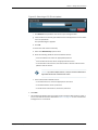
Logging In to Junos Space . . . . . . . . . . . . . . . . . . . . . . . . . . . . . . . . . . . . . . . . . . . . . 3
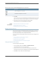
Changing User Passwords . . . . . . . . . . . . . . . . . . . . . . . . . . . . . . . . . . . . . . . . . . . . . 4
Using the Getting Started Assistants . . . . . . . . . . . . . . . . . . . . . . . . . . . . . . . . . . . . 5
Accessing Help . . . . . . . . . . . . . . . . . . . . . . . . . . . . . . . . . . . . . . . . . . . . . . . . . . . . . . 6
Logging Out of the Junos Space System . . . . . . . . . . . . . . . . . . . . . . . . . . . . . . . . . . 7
Chapter 2
Understanding the Junos Space User Interface . . . . . . . . . . . . . . . . . . . . . . . . 9
Application Chooser Overview . . . . . . . . . . . . . . . . . . . . . . . . . . . . . . . . . . . . . . . . . 9
Parts of the Application Chooser . . . . . . . . . . . . . . . . . . . . . . . . . . . . . . . . . . . . 9
Application Icons . . . . . . . . . . . . . . . . . . . . . . . . . . . . . . . . . . . . . . . . . . . . . 9
Shortcut Icons . . . . . . . . . . . . . . . . . . . . . . . . . . . . . . . . . . . . . . . . . . . . . . 10
Login User Name . . . . . . . . . . . . . . . . . . . . . . . . . . . . . . . . . . . . . . . . . . . . . 11
Application Chooser Actions . . . . . . . . . . . . . . . . . . . . . . . . . . . . . . . . . . . . . . . 11
Junos Space User Interface Overview . . . . . . . . . . . . . . . . . . . . . . . . . . . . . . . . . . . . 11
Parts of the System User Interface . . . . . . . . . . . . . . . . . . . . . . . . . . . . . . . . . . 12
Banner . . . . . . . . . . . . . . . . . . . . . . . . . . . . . . . . . . . . . . . . . . . . . . . . . . . . . 12
Application Chooser . . . . . . . . . . . . . . . . . . . . . . . . . . . . . . . . . . . . . . . . . . 13
Application Dashboard . . . . . . . . . . . . . . . . . . . . . . . . . . . . . . . . . . . . . . . . 13
Workspace Statistics . . . . . . . . . . . . . . . . . . . . . . . . . . . . . . . . . . . . . . . . . 14
Inventory Page . . . . . . . . . . . . . . . . . . . . . . . . . . . . . . . . . . . . . . . . . . . . . . 14
Navigating the Junos Space User Interface . . . . . . . . . . . . . . . . . . . . . . . . . . . . . . . 16
Navigating Applications Using the Application Chooser . . . . . . . . . . . . . . . . . 16
Navigating Applications Using the Application Switcher . . . . . . . . . . . . . . . . . 16
Navigating Application Workspaces and Tasks Using the Navigation
Ribbon . . . . . . . . . . . . . . . . . . . . . . . . . . . . . . . . . . . . . . . . . . . . . . . . . . . . . 17
Navigating to the Dashboard of an Application . . . . . . . . . . . . . . . . . . . . . . . . 18
Navigating to a Workspace from a Task . . . . . . . . . . . . . . . . . . . . . . . . . . . . . . 18
Network Application Platform Overview . . . . . . . . . . . . . . . . . . . . . . . . . . . . . . . . . 18
Copyright © 2014, Juniper Networks, Inc.
iii
Junos Space Network Application Platform User Guide
Platform Dashboard Overview . . . . . . . . . . . . . . . . . . . . . . . . . . . . . . . . . . . . . . . . . 19
Parts of Platform Dashboard . . . . . . . . . . . . . . . . . . . . . . . . . . . . . . . . . . . . . . 20
Workspace Navigation Ribbon . . . . . . . . . . . . . . . . . . . . . . . . . . . . . . . . . 20
Dashboard Gadgets . . . . . . . . . . . . . . . . . . . . . . . . . . . . . . . . . . . . . . . . . . 21
Viewing Dashboard Statistics . . . . . . . . . . . . . . . . . . . . . . . . . . . . . . . . . . . . . . . . . 23
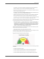
Viewing System Health Statistics . . . . . . . . . . . . . . . . . . . . . . . . . . . . . . . . . . . 23
Viewing the Job Information . . . . . . . . . . . . . . . . . . . . . . . . . . . . . . . . . . . . . . . 25
Workspace Statistics Pages Overview . . . . . . . . . . . . . . . . . . . . . . . . . . . . . . . . . . 26
Inventory Pages Overview . . . . . . . . . . . . . . . . . . . . . . . . . . . . . . . . . . . . . . . . . . . . 28
Parts of the Inventory Page . . . . . . . . . . . . . . . . . . . . . . . . . . . . . . . . . . . . . . . 29
View Controls . . . . . . . . . . . . . . . . . . . . . . . . . . . . . . . . . . . . . . . . . . . . . . . 31
Sorted By Indicator . . . . . . . . . . . . . . . . . . . . . . . . . . . . . . . . . . . . . . . . . . 32
Show or Hide Columns . . . . . . . . . . . . . . . . . . . . . . . . . . . . . . . . . . . . . . . 32
Filter Submenus . . . . . . . . . . . . . . . . . . . . . . . . . . . . . . . . . . . . . . . . . . . . . 33
Zoom Slider . . . . . . . . . . . . . . . . . . . . . . . . . . . . . . . . . . . . . . . . . . . . . . . . 33
Search Field . . . . . . . . . . . . . . . . . . . . . . . . . . . . . . . . . . . . . . . . . . . . . . . . 33
Actions Drawer . . . . . . . . . . . . . . . . . . . . . . . . . . . . . . . . . . . . . . . . . . . . . . 34
Paging Controls . . . . . . . . . . . . . . . . . . . . . . . . . . . . . . . . . . . . . . . . . . . . . 34
Filtering Inventory Pages . . . . . . . . . . . . . . . . . . . . . . . . . . . . . . . . . . . . . . . . . . . . . 35
Part 2
Devices
Chapter 3
Discovering Devices . . . . . . . . . . . . . . . . . . . . . . . . . . . . . . . . . . . . . . . . . . . . . . . . 41
Device Discovery Overview . . . . . . . . . . . . . . . . . . . . . . . . . . . . . . . . . . . . . . . . . . . . 41
Discovering Devices . . . . . . . . . . . . . . . . . . . . . . . . . . . . . . . . . . . . . . . . . . . . . . . . . 42
Specifying Device Targets . . . . . . . . . . . . . . . . . . . . . . . . . . . . . . . . . . . . . . . . . 43
Specifying Probes . . . . . . . . . . . . . . . . . . . . . . . . . . . . . . . . . . . . . . . . . . . . . . . 45
Specifying Credentials . . . . . . . . . . . . . . . . . . . . . . . . . . . . . . . . . . . . . . . . . . . 47
Chapter 4
Adding Deployed Devices . . . . . . . . . . . . . . . . . . . . . . . . . . . . . . . . . . . . . . . . . . . 51
Add Deployed Devices Wizard Overview . . . . . . . . . . . . . . . . . . . . . . . . . . . . . . . . . 51
Adding Deployed Devices . . . . . . . . . . . . . . . . . . . . . . . . . . . . . . . . . . . . . . . . . . . . . 52
Managing Deployed Devices . . . . . . . . . . . . . . . . . . . . . . . . . . . . . . . . . . . . . . . . . . 54
Viewing the Details of a Task Instance . . . . . . . . . . . . . . . . . . . . . . . . . . . . . . . 54
Viewing the Device Status . . . . . . . . . . . . . . . . . . . . . . . . . . . . . . . . . . . . . . . . 55
Deleting a Task Instance . . . . . . . . . . . . . . . . . . . . . . . . . . . . . . . . . . . . . . . . . . 55
Downloading Management CLI Commands . . . . . . . . . . . . . . . . . . . . . . . . . . 55
Chapter 5
Device Management Overview . . . . . . . . . . . . . . . . . . . . . . . . . . . . . . . . . . . . . . 57
Device Management Overview . . . . . . . . . . . . . . . . . . . . . . . . . . . . . . . . . . . . . . . . 57
Viewing Device Statistics . . . . . . . . . . . . . . . . . . . . . . . . . . . . . . . . . . . . . . . . . . . . . 58
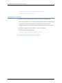
Viewing the Number of Devices by Platform . . . . . . . . . . . . . . . . . . . . . . . . . . 59
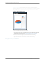
Viewing Connection Status for Devices . . . . . . . . . . . . . . . . . . . . . . . . . . . . . . 59
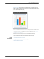
Viewing Devices by Junos OS Release . . . . . . . . . . . . . . . . . . . . . . . . . . . . . . . 60
Device Inventory Management Overview . . . . . . . . . . . . . . . . . . . . . . . . . . . . . . . . 62
iv
Copyright © 2014, Juniper Networks, Inc.
Table of Contents
Chapter 6
Managing Devices . . . . . . . . . . . . . . . . . . . . . . . . . . . . . . . . . . . . . . . . . . . . . . . . . 63
Viewing Managed Devices . . . . . . . . . . . . . . . . . . . . . . . . . . . . . . . . . . . . . . . . . . . . 64
Viewing Devices as Graphics . . . . . . . . . . . . . . . . . . . . . . . . . . . . . . . . . . . . . . 64
Viewing Devices in a Table . . . . . . . . . . . . . . . . . . . . . . . . . . . . . . . . . . . . . . . . 65
Editing Device Configuration Overview . . . . . . . . . . . . . . . . . . . . . . . . . . . . . . . . . . 68
Selecting the Device and the Configuration Perspective . . . . . . . . . . . . . . . . . . . . 69
Editing Device Configuration Options . . . . . . . . . . . . . . . . . . . . . . . . . . . . . . . . . . . 70
Finalizing Device Configuration Changes . . . . . . . . . . . . . . . . . . . . . . . . . . . . . . . . . 72
Viewing Change Requests . . . . . . . . . . . . . . . . . . . . . . . . . . . . . . . . . . . . . . . . . . . . 74
Viewing Change Requests . . . . . . . . . . . . . . . . . . . . . . . . . . . . . . . . . . . . . . . . 74
Adding, Modifying, or Deleting a Change Request . . . . . . . . . . . . . . . . . . . . . . 74
Viewing Hardware Inventory for Devices . . . . . . . . . . . . . . . . . . . . . . . . . . . . . . . . . 75
Viewing Physical Interfaces for Devices . . . . . . . . . . . . . . . . . . . . . . . . . . . . . . . . . 78
Viewing Logical Interfaces for Devices . . . . . . . . . . . . . . . . . . . . . . . . . . . . . . . . . . 79
Deleting Devices . . . . . . . . . . . . . . . . . . . . . . . . . . . . . . . . . . . . . . . . . . . . . . . . . . . . 81
Resynchronizing Managed Devices . . . . . . . . . . . . . . . . . . . . . . . . . . . . . . . . . . . . . 82
Changing Login Credentials for Managed Devices . . . . . . . . . . . . . . . . . . . . . . . . . 84
Displaying Service Contract and EOL Data in the Physical Inventory Table . . . . . 86
Exporting Device Inventory Information . . . . . . . . . . . . . . . . . . . . . . . . . . . . . . . . . 89
Viewing and Exporting Device Software Inventory . . . . . . . . . . . . . . . . . . . . . . . . . 93
Launching a Device’s Web UI from Junos Space . . . . . . . . . . . . . . . . . . . . . . . . . . 94
Understanding Logical Systems for SRX Series Services Gateways . . . . . . . . . . . 95
Viewing Devices and Logical Systems with Quickview . . . . . . . . . . . . . . . . . . . . . 96
Viewing the Physical Device for a Logical System . . . . . . . . . . . . . . . . . . . . . . . . . 97
Viewing Logical Systems for a Physical Device . . . . . . . . . . . . . . . . . . . . . . . . . . . 98
Creating a New Logical System . . . . . . . . . . . . . . . . . . . . . . . . . . . . . . . . . . . . . . . . 99
Deleting Logical Systems . . . . . . . . . . . . . . . . . . . . . . . . . . . . . . . . . . . . . . . . . . . . 99
Viewing and Exporting Device License Inventory . . . . . . . . . . . . . . . . . . . . . . . . . . 101
Putting a Device in RMA State and Reactivating Its Replacement . . . . . . . . . . . . 103
Putting a Device in RMA State . . . . . . . . . . . . . . . . . . . . . . . . . . . . . . . . . . . . 104
Reactivating a Replacement Device . . . . . . . . . . . . . . . . . . . . . . . . . . . . . . . . 105
Managing Hierarchical Tags . . . . . . . . . . . . . . . . . . . . . . . . . . . . . . . . . . . . . . . . . . 105
Using the Tag Hierarchy Pane . . . . . . . . . . . . . . . . . . . . . . . . . . . . . . . . . . . . . 106
Using the Tag Action Bar . . . . . . . . . . . . . . . . . . . . . . . . . . . . . . . . . . . . . 106
Using the Right-Click Menu– . . . . . . . . . . . . . . . . . . . . . . . . . . . . . . . . . . 107
Using Drag-and-Drop . . . . . . . . . . . . . . . . . . . . . . . . . . . . . . . . . . . . . . . 108
Using the Quick Info Tool Tip . . . . . . . . . . . . . . . . . . . . . . . . . . . . . . . . . . 108
Browsing Tagged Objects . . . . . . . . . . . . . . . . . . . . . . . . . . . . . . . . . . . . 108
Viewing All Tags . . . . . . . . . . . . . . . . . . . . . . . . . . . . . . . . . . . . . . . . . . . . 108
Adding a Child Tag . . . . . . . . . . . . . . . . . . . . . . . . . . . . . . . . . . . . . . . . . . 108
Deleting a Tag . . . . . . . . . . . . . . . . . . . . . . . . . . . . . . . . . . . . . . . . . . . . . . 109
Using Notification . . . . . . . . . . . . . . . . . . . . . . . . . . . . . . . . . . . . . . . . . . 109
Using the Tabular View Pane . . . . . . . . . . . . . . . . . . . . . . . . . . . . . . . . . . . . . 109
Troubleshooting Devices . . . . . . . . . . . . . . . . . . . . . . . . . . . . . . . . . . . . . . . . . . . . . 110
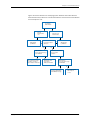
Understanding How Junos Space Automatically Resynchronizes Managed
Devices . . . . . . . . . . . . . . . . . . . . . . . . . . . . . . . . . . . . . . . . . . . . . . . . . . . . . . . 112
Network as System of Record . . . . . . . . . . . . . . . . . . . . . . . . . . . . . . . . . . . . . 112
Junos Space as System of Record . . . . . . . . . . . . . . . . . . . . . . . . . . . . . . . . . . 114
Copyright © 2014, Juniper Networks, Inc.
v
Junos Space Network Application Platform User Guide
Chapter 7
Adding Devices and Connection Profiles . . . . . . . . . . . . . . . . . . . . . . . . . . . . . 115
Add Devices Overview . . . . . . . . . . . . . . . . . . . . . . . . . . . . . . . . . . . . . . . . . . . . . . . 115
Adding Devices . . . . . . . . . . . . . . . . . . . . . . . . . . . . . . . . . . . . . . . . . . . . . . . . . . . . . 117
Creating a Deployment Instance . . . . . . . . . . . . . . . . . . . . . . . . . . . . . . . . . . . 118
Adding a Deployment Instance by Importing a CSV File . . . . . . . . . . . . . . . . . 119
Adding a Deployment Instance Manually . . . . . . . . . . . . . . . . . . . . . . . . . . . . 120
Working with Rows and Columns . . . . . . . . . . . . . . . . . . . . . . . . . . . . . . . . . . 121
Working with Configlets . . . . . . . . . . . . . . . . . . . . . . . . . . . . . . . . . . . . . . . . . . 123
Deploying Device Instances . . . . . . . . . . . . . . . . . . . . . . . . . . . . . . . . . . . . . . . . . . 124
Viewing the Details of a Deployment Instance . . . . . . . . . . . . . . . . . . . . . . . . 124
Viewing the Device Status . . . . . . . . . . . . . . . . . . . . . . . . . . . . . . . . . . . . . . . . 124
Deleting a Deployment Instance . . . . . . . . . . . . . . . . . . . . . . . . . . . . . . . . . . . 125
Downloading Configlets . . . . . . . . . . . . . . . . . . . . . . . . . . . . . . . . . . . . . . . . . 125
Searching for a Deployment Instance . . . . . . . . . . . . . . . . . . . . . . . . . . . . . . . 126
Connection Profiles Overview . . . . . . . . . . . . . . . . . . . . . . . . . . . . . . . . . . . . . . . . . 127
Creating Connection Profiles . . . . . . . . . . . . . . . . . . . . . . . . . . . . . . . . . . . . . . . . . 129
Managing Connection Profiles . . . . . . . . . . . . . . . . . . . . . . . . . . . . . . . . . . . . . . . . 132
Viewing the Details of a Connection Profile . . . . . . . . . . . . . . . . . . . . . . . . . . 133
Modifying a Connection Profile . . . . . . . . . . . . . . . . . . . . . . . . . . . . . . . . . . . . 134
Deleting a Connection Profile . . . . . . . . . . . . . . . . . . . . . . . . . . . . . . . . . . . . . 134
Copying a Connection Profile . . . . . . . . . . . . . . . . . . . . . . . . . . . . . . . . . . . . . 135
Searching for a Connection Profile . . . . . . . . . . . . . . . . . . . . . . . . . . . . . . . . . 135
Chapter 8
Secure Console . . . . . . . . . . . . . . . . . . . . . . . . . . . . . . . . . . . . . . . . . . . . . . . . . . . 137
Connecting to a Device . . . . . . . . . . . . . . . . . . . . . . . . . . . . . . . . . . . . . . . . . . . . . . 137
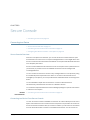
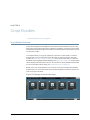
Secure Console Overview . . . . . . . . . . . . . . . . . . . . . . . . . . . . . . . . . . . . . . . . 137
Connecting to a Device From Secure Console . . . . . . . . . . . . . . . . . . . . . . . . 137
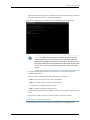
Connecting to a Managed Device . . . . . . . . . . . . . . . . . . . . . . . . . . . . . . 138
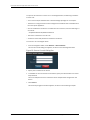
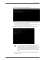
Connecting to an Unmanaged Device . . . . . . . . . . . . . . . . . . . . . . . . . . . 139
Configuring SRX Device Clusters in Junos Space . . . . . . . . . . . . . . . . . . . . . . 142
Configuring a Standalone Device from a Single-node Cluster . . . . . . . . 142
Configuring a Standalone Device from a Two-Node Cluster . . . . . . . . . 144
Configuring a Primary Peer in a Cluster from a Standalone Device . . . . 145
Configuring a Secondary Peer in a Cluster from a Standalone
Device . . . . . . . . . . . . . . . . . . . . . . . . . . . . . . . . . . . . . . . . . . . . . . . . 146
Chapter 9
Device Adapters . . . . . . . . . . . . . . . . . . . . . . . . . . . . . . . . . . . . . . . . . . . . . . . . . 149
Installation/Management . . . . . . . . . . . . . . . . . . . . . . . . . . . . . . . . . . . . . . . . . . . 149
Worldwide Junos OS Adapter Overview . . . . . . . . . . . . . . . . . . . . . . . . . . . . . 149
Installing the Worldwide Junos OS Adapter . . . . . . . . . . . . . . . . . . . . . . . . . . 150
Installing the wwadapter Image . . . . . . . . . . . . . . . . . . . . . . . . . . . . . . . 150
Connecting to ww Junos OS Devices . . . . . . . . . . . . . . . . . . . . . . . . . . . . 152
Chapter 10
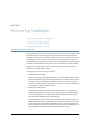
Discovering Topologies . . . . . . . . . . . . . . . . . . . . . . . . . . . . . . . . . . . . . . . . . . . . 155
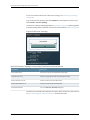
Topology Discovery Overview . . . . . . . . . . . . . . . . . . . . . . . . . . . . . . . . . . . . . . . . . 155
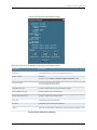
Discovering a Topology . . . . . . . . . . . . . . . . . . . . . . . . . . . . . . . . . . . . . . . . . . . . . . 158
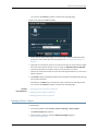
Managing Device Targets . . . . . . . . . . . . . . . . . . . . . . . . . . . . . . . . . . . . . . . . . . . . 159
Managing SNMP Probes . . . . . . . . . . . . . . . . . . . . . . . . . . . . . . . . . . . . . . . . . . . . . 161
vi
Copyright © 2014, Juniper Networks, Inc.
Table of Contents
Part 3
Device Templates
Chapter 11
Overview . . . . . . . . . . . . . . . . . . . . . . . . . . . . . . . . . . . . . . . . . . . . . . . . . . . . . . . . 167
Device Templates Overview . . . . . . . . . . . . . . . . . . . . . . . . . . . . . . . . . . . . . . . . . . 167
Device Templates Overview . . . . . . . . . . . . . . . . . . . . . . . . . . . . . . . . . . . . . . 168
Device Templates Workflow . . . . . . . . . . . . . . . . . . . . . . . . . . . . . . . . . . . . . . 170
Viewing Statistics for Templates and Definitions . . . . . . . . . . . . . . . . . . . . . . 170
Chapter 12
Template Definitions . . . . . . . . . . . . . . . . . . . . . . . . . . . . . . . . . . . . . . . . . . . . . . 173
Managing Template Definitions . . . . . . . . . . . . . . . . . . . . . . . . . . . . . . . . . . . . . . . 173
Managing Template Definitions . . . . . . . . . . . . . . . . . . . . . . . . . . . . . . . . . . . . 173
Publishing and Unpublishing a Template Definition . . . . . . . . . . . . . . . . . . . . 174
Modifying a Template Definition . . . . . . . . . . . . . . . . . . . . . . . . . . . . . . . . . . . 175
Cloning a Template Definition . . . . . . . . . . . . . . . . . . . . . . . . . . . . . . . . . . . . . 176
Deleting a Template Definition . . . . . . . . . . . . . . . . . . . . . . . . . . . . . . . . . . . . 177
Importing Template Definitions Overview . . . . . . . . . . . . . . . . . . . . . . . . . . . . 177
Importing a Template Definition . . . . . . . . . . . . . . . . . . . . . . . . . . . . . . . . . . . 178
Exporting a Template Definition . . . . . . . . . . . . . . . . . . . . . . . . . . . . . . . . . . . 179
Viewing Template Definition Inventory . . . . . . . . . . . . . . . . . . . . . . . . . . . . . . 180
Creating a Template Definition . . . . . . . . . . . . . . . . . . . . . . . . . . . . . . . . . . . . . . . 180
Creating a Template Definition Overview . . . . . . . . . . . . . . . . . . . . . . . . . . . . 181
Creating a Template Definition . . . . . . . . . . . . . . . . . . . . . . . . . . . . . . . . . . . . 181
Selecting the Device Family and Naming the Definition . . . . . . . . . . . . . 182
Creating Configuration Pages . . . . . . . . . . . . . . . . . . . . . . . . . . . . . . . . . 183
Determining Editable Parameters . . . . . . . . . . . . . . . . . . . . . . . . . . . . . . 186
Filling in the General Tab . . . . . . . . . . . . . . . . . . . . . . . . . . . . . . . . . . . . . 187
Filling in the Description Tab . . . . . . . . . . . . . . . . . . . . . . . . . . . . . . . . . . 189
Filling in the Validation Tab . . . . . . . . . . . . . . . . . . . . . . . . . . . . . . . . . . . 190
Filling in the Advanced Tab . . . . . . . . . . . . . . . . . . . . . . . . . . . . . . . . . . . 194
Specifying Default Values for Configuration Options . . . . . . . . . . . . . . . 194
Finding Configuration Options . . . . . . . . . . . . . . . . . . . . . . . . . . . . . . . . . . . . 196
Specifying Device-Specific Values in Definitions . . . . . . . . . . . . . . . . . . . . . . 199
Managing CSV Files . . . . . . . . . . . . . . . . . . . . . . . . . . . . . . . . . . . . . . . . . . . . 203
Working with Rules . . . . . . . . . . . . . . . . . . . . . . . . . . . . . . . . . . . . . . . . . . . . . 204
Chapter 13
Templates . . . . . . . . . . . . . . . . . . . . . . . . . . . . . . . . . . . . . . . . . . . . . . . . . . . . . . 207
Creating and Managing Templates . . . . . . . . . . . . . . . . . . . . . . . . . . . . . . . . . . . . 207
Managing Templates Overview . . . . . . . . . . . . . . . . . . . . . . . . . . . . . . . . . . . 207
Template States . . . . . . . . . . . . . . . . . . . . . . . . . . . . . . . . . . . . . . . . . . . 208
Filtering and Searching Templates . . . . . . . . . . . . . . . . . . . . . . . . . . . . . 208
Device Template Detailed Information . . . . . . . . . . . . . . . . . . . . . . . . . . 209
Template Actions . . . . . . . . . . . . . . . . . . . . . . . . . . . . . . . . . . . . . . . . . . 209
Creating a Template Overview . . . . . . . . . . . . . . . . . . . . . . . . . . . . . . . . . . . . 210
Creating a Template . . . . . . . . . . . . . . . . . . . . . . . . . . . . . . . . . . . . . . . . . . . . 210
Selecting a Template Definition . . . . . . . . . . . . . . . . . . . . . . . . . . . . . . . . 211
Naming and Describing a Template . . . . . . . . . . . . . . . . . . . . . . . . . . . . . 211
Entering Data and Finishing the Template . . . . . . . . . . . . . . . . . . . . . . . . 212
Copyright © 2014, Juniper Networks, Inc.
vii
Junos Space Network Application Platform User Guide
Deploying the Template . . . . . . . . . . . . . . . . . . . . . . . . . . . . . . . . . . . . . . 213
Deploying a Template . . . . . . . . . . . . . . . . . . . . . . . . . . . . . . . . . . . . . . . . . . . 213
Undeploying a Template . . . . . . . . . . . . . . . . . . . . . . . . . . . . . . . . . . . . . . . . . 215
Viewing Template Deployment . . . . . . . . . . . . . . . . . . . . . . . . . . . . . . . . . . . . 216
Auditing Template Configuration . . . . . . . . . . . . . . . . . . . . . . . . . . . . . . . . . . 219
Modifying a Template . . . . . . . . . . . . . . . . . . . . . . . . . . . . . . . . . . . . . . . . . . . 219
Deleting a Template . . . . . . . . . . . . . . . . . . . . . . . . . . . . . . . . . . . . . . . . . . . . 220
Viewing Template Inventory . . . . . . . . . . . . . . . . . . . . . . . . . . . . . . . . . . . . . . 221
Viewing Template Statistics . . . . . . . . . . . . . . . . . . . . . . . . . . . . . . . . . . . . . . 221
Chapter 14
Troubleshooting . . . . . . . . . . . . . . . . . . . . . . . . . . . . . . . . . . . . . . . . . . . . . . . . . 223
Troubleshooting . . . . . . . . . . . . . . . . . . . . . . . . . . . . . . . . . . . . . . . . . . . . . . . . . . . 223
Viewing Audit Logs . . . . . . . . . . . . . . . . . . . . . . . . . . . . . . . . . . . . . . . . . . . . . 223
Viewing Your Jobs . . . . . . . . . . . . . . . . . . . . . . . . . . . . . . . . . . . . . . . . . . . . . . 225
Changing Template Definition States . . . . . . . . . . . . . . . . . . . . . . . . . . . . . . 226
User Privileges in Device Templates . . . . . . . . . . . . . . . . . . . . . . . . . . . . . . . . 226
Part 4
Device Images and Scripts
Chapter 15
Overview . . . . . . . . . . . . . . . . . . . . . . . . . . . . . . . . . . . . . . . . . . . . . . . . . . . . . . . . 231
Device Images and Scripts Overview . . . . . . . . . . . . . . . . . . . . . . . . . . . . . . . . . . . 231
User Roles . . . . . . . . . . . . . . . . . . . . . . . . . . . . . . . . . . . . . . . . . . . . . . . . . . . . 232
Chapter 16
Device Images . . . . . . . . . . . . . . . . . . . . . . . . . . . . . . . . . . . . . . . . . . . . . . . . . . . 235
Device Images Overview . . . . . . . . . . . . . . . . . . . . . . . . . . . . . . . . . . . . . . . . . . . . 235
Chapter 17
Scripts . . . . . . . . . . . . . . . . . . . . . . . . . . . . . . . . . . . . . . . . . . . . . . . . . . . . . . . . . . 237
Scripts Overview . . . . . . . . . . . . . . . . . . . . . . . . . . . . . . . . . . . . . . . . . . . . . . . . . . . 237
Chapter 18
Operations . . . . . . . . . . . . . . . . . . . . . . . . . . . . . . . . . . . . . . . . . . . . . . . . . . . . . . 241
Operations Overview . . . . . . . . . . . . . . . . . . . . . . . . . . . . . . . . . . . . . . . . . . . . . . . 241
Chapter 19
Script Bundles . . . . . . . . . . . . . . . . . . . . . . . . . . . . . . . . . . . . . . . . . . . . . . . . . . . 243
Script Bundles Overview . . . . . . . . . . . . . . . . . . . . . . . . . . . . . . . . . . . . . . . . . . . . 243
Chapter 20
Configuration: Device Images . . . . . . . . . . . . . . . . . . . . . . . . . . . . . . . . . . . . . . 245
Uploading Device Images to Junos Space . . . . . . . . . . . . . . . . . . . . . . . . . . . . . . 245
Staging Device Images . . . . . . . . . . . . . . . . . . . . . . . . . . . . . . . . . . . . . . . . . . . . . 246
Verifying the Checksum . . . . . . . . . . . . . . . . . . . . . . . . . . . . . . . . . . . . . . . . . . . . . 247
Viewing and Deleting MD5 Validation Results . . . . . . . . . . . . . . . . . . . . . . . . . . . 248
Viewing the MD5 Validation Results . . . . . . . . . . . . . . . . . . . . . . . . . . . . . . . 248
Deleting the MD5 Validation Results . . . . . . . . . . . . . . . . . . . . . . . . . . . . . . . 249
Deploying Device Images . . . . . . . . . . . . . . . . . . . . . . . . . . . . . . . . . . . . . . . . . . . . 250
Viewing Device Image Deployment Results . . . . . . . . . . . . . . . . . . . . . . . . . . . . . 255
Deleting Device Images . . . . . . . . . . . . . . . . . . . . . . . . . . . . . . . . . . . . . . . . . . . . . 255
Modifying Device Image Details . . . . . . . . . . . . . . . . . . . . . . . . . . . . . . . . . . . . . . 256
Chapter 21
Configuration: Scripts . . . . . . . . . . . . . . . . . . . . . . . . . . . . . . . . . . . . . . . . . . . . 259
Importing a Script . . . . . . . . . . . . . . . . . . . . . . . . . . . . . . . . . . . . . . . . . . . . . . . . . 259
Modifying a Script . . . . . . . . . . . . . . . . . . . . . . . . . . . . . . . . . . . . . . . . . . . . . . . . . 260
Modifying Script Types . . . . . . . . . . . . . . . . . . . . . . . . . . . . . . . . . . . . . . . . . . . . . . 261
Comparing Script Versions . . . . . . . . . . . . . . . . . . . . . . . . . . . . . . . . . . . . . . . . . . 262
viii
Copyright © 2014, Juniper Networks, Inc.
Table of Contents
Deleting Scripts . . . . . . . . . . . . . . . . . . . . . . . . . . . . . . . . . . . . . . . . . . . . . . . . . . . 263
Deploying Scripts on Devices . . . . . . . . . . . . . . . . . . . . . . . . . . . . . . . . . . . . . . . . 264
Verifying the Checksum of Scripts on Devices . . . . . . . . . . . . . . . . . . . . . . . . . . . 266
Enabling Scripts on Devices . . . . . . . . . . . . . . . . . . . . . . . . . . . . . . . . . . . . . . . . . . 267
Removing Scripts from Devices . . . . . . . . . . . . . . . . . . . . . . . . . . . . . . . . . . . . . . 269
Executing Scripts on Devices . . . . . . . . . . . . . . . . . . . . . . . . . . . . . . . . . . . . . . . . . 269
Chapter 22
Configuration: Operations . . . . . . . . . . . . . . . . . . . . . . . . . . . . . . . . . . . . . . . . . 273
Creating an Operation . . . . . . . . . . . . . . . . . . . . . . . . . . . . . . . . . . . . . . . . . . . . . . 273
Modifying an Operation . . . . . . . . . . . . . . . . . . . . . . . . . . . . . . . . . . . . . . . . . . . . . 276
Running an Operation . . . . . . . . . . . . . . . . . . . . . . . . . . . . . . . . . . . . . . . . . . . . . . . 277
Copying an Operation . . . . . . . . . . . . . . . . . . . . . . . . . . . . . . . . . . . . . . . . . . . . . . 279
Deleting an Operation . . . . . . . . . . . . . . . . . . . . . . . . . . . . . . . . . . . . . . . . . . . . . . 279
Chapter 23
Configuration: Script Bundles . . . . . . . . . . . . . . . . . . . . . . . . . . . . . . . . . . . . . . 281
Creating a Script Bundle . . . . . . . . . . . . . . . . . . . . . . . . . . . . . . . . . . . . . . . . . . . . . 281
Modifying a Script Bundle . . . . . . . . . . . . . . . . . . . . . . . . . . . . . . . . . . . . . . . . . . . 282
Deleting Script Bundles . . . . . . . . . . . . . . . . . . . . . . . . . . . . . . . . . . . . . . . . . . . . . 284
Deploying Script Bundles on Devices . . . . . . . . . . . . . . . . . . . . . . . . . . . . . . . . . . 284
Executing Script Bundles on Devices . . . . . . . . . . . . . . . . . . . . . . . . . . . . . . . . . . 285
Chapter 24
Administration: Scripts . . . . . . . . . . . . . . . . . . . . . . . . . . . . . . . . . . . . . . . . . . . 289
Viewing Script Details . . . . . . . . . . . . . . . . . . . . . . . . . . . . . . . . . . . . . . . . . . . . . . 289
Viewing Verification Results . . . . . . . . . . . . . . . . . . . . . . . . . . . . . . . . . . . . . . . . . . 291
Exporting Scripts in Tar Format . . . . . . . . . . . . . . . . . . . . . . . . . . . . . . . . . . . . . . . 292
Chapter 25
Administration: Operations . . . . . . . . . . . . . . . . . . . . . . . . . . . . . . . . . . . . . . . 293
Viewing Operations Results . . . . . . . . . . . . . . . . . . . . . . . . . . . . . . . . . . . . . . . . . . 293
Part 5
Network Monitoring
Chapter 26
Network Monitoring UI . . . . . . . . . . . . . . . . . . . . . . . . . . . . . . . . . . . . . . . . . . . . 297
Network Monitoring workspace . . . . . . . . . . . . . . . . . . . . . . . . . . . . . . . . . . . . . . . 297
Network Monitoring Workspace Overview . . . . . . . . . . . . . . . . . . . . . . . . . . 298
Network Monitoring Reports Overview . . . . . . . . . . . . . . . . . . . . . . . . . . . . . 300
Resource Graphs . . . . . . . . . . . . . . . . . . . . . . . . . . . . . . . . . . . . . . . . . . . 300
Key SNMP Customized (KSC) Performance Reports, Node Reports,
and Domain Reports . . . . . . . . . . . . . . . . . . . . . . . . . . . . . . . . . . . . 300
Database Reports . . . . . . . . . . . . . . . . . . . . . . . . . . . . . . . . . . . . . . . . . . 300
Statistics Reports . . . . . . . . . . . . . . . . . . . . . . . . . . . . . . . . . . . . . . . . . . 300
Viewing the Node List . . . . . . . . . . . . . . . . . . . . . . . . . . . . . . . . . . . . . . . . . . . 301
Resyncing Nodes . . . . . . . . . . . . . . . . . . . . . . . . . . . . . . . . . . . . . . . . . . . . . . 302
Searching in the Network Monitoring Workspace . . . . . . . . . . . . . . . . . . . . . 302
Viewing the Dashboard . . . . . . . . . . . . . . . . . . . . . . . . . . . . . . . . . . . . . . . . . 304
Tracking and Searching for Assets . . . . . . . . . . . . . . . . . . . . . . . . . . . . . . . . . 306
Viewing and Tracking Outages . . . . . . . . . . . . . . . . . . . . . . . . . . . . . . . . . . . 306
Viewing, Querying, and Acknowledging Events . . . . . . . . . . . . . . . . . . . . . . . 307
Events Landing Page . . . . . . . . . . . . . . . . . . . . . . . . . . . . . . . . . . . . . . . . 307
Advanced Event Search . . . . . . . . . . . . . . . . . . . . . . . . . . . . . . . . . . . . . 308
Viewing the Events List . . . . . . . . . . . . . . . . . . . . . . . . . . . . . . . . . . . . . . 308
Copyright © 2014, Juniper Networks, Inc.
ix
Junos Space Network Application Platform User Guide
Viewing Event Details . . . . . . . . . . . . . . . . . . . . . . . . . . . . . . . . . . . . . . . 309
Viewing and Acknowledging Alarms . . . . . . . . . . . . . . . . . . . . . . . . . . . . . . . 310
Viewing Alarms . . . . . . . . . . . . . . . . . . . . . . . . . . . . . . . . . . . . . . . . . . . . . 311
Acknowledging Alarms . . . . . . . . . . . . . . . . . . . . . . . . . . . . . . . . . . . . . . . 312
Clearing Alarms . . . . . . . . . . . . . . . . . . . . . . . . . . . . . . . . . . . . . . . . . . . . 313
Escalating Alarms . . . . . . . . . . . . . . . . . . . . . . . . . . . . . . . . . . . . . . . . . . . 313
Unacknowledging Alarms . . . . . . . . . . . . . . . . . . . . . . . . . . . . . . . . . . . . 313
Viewing Acknowledged Alarms . . . . . . . . . . . . . . . . . . . . . . . . . . . . . . . . 313
Viewing, Configuring, and Searching for Notifications . . . . . . . . . . . . . . . . . . 314
Notification Escalation . . . . . . . . . . . . . . . . . . . . . . . . . . . . . . . . . . . . . . . 314
Creating Reports . . . . . . . . . . . . . . . . . . . . . . . . . . . . . . . . . . . . . . . . . . . . . . . 315
Creating Key SNMP Customized Performance Reports, Node Reports,
Domain Reports . . . . . . . . . . . . . . . . . . . . . . . . . . . . . . . . . . . . . . . . 315
Creating a New KSC Report from an Existing Report . . . . . . . . . . . . . . . 315
Viewing Reports . . . . . . . . . . . . . . . . . . . . . . . . . . . . . . . . . . . . . . . . . . . . . . . . 316
Viewing Resource Graphs . . . . . . . . . . . . . . . . . . . . . . . . . . . . . . . . . . . . 316
Viewing Key SNMP Customized (KSC) Performance Reports, Node
Reports, Domain Reports . . . . . . . . . . . . . . . . . . . . . . . . . . . . . . . . . 317
Viewing Database Reports . . . . . . . . . . . . . . . . . . . . . . . . . . . . . . . . . . . . 317
Sending Database Reports . . . . . . . . . . . . . . . . . . . . . . . . . . . . . . . . . . . 318
Viewing Pre-run Database Reports . . . . . . . . . . . . . . . . . . . . . . . . . . . . . 319
Viewing Statistics Reports . . . . . . . . . . . . . . . . . . . . . . . . . . . . . . . . . . . . 319
Generating a Statistics Report for Export . . . . . . . . . . . . . . . . . . . . . . . . 319
Deleting Reports . . . . . . . . . . . . . . . . . . . . . . . . . . . . . . . . . . . . . . . . . . . . . . . 320
Deleting Key SNMP Customized Reports . . . . . . . . . . . . . . . . . . . . . . . . 320
Deleting Pre-run Database Reports . . . . . . . . . . . . . . . . . . . . . . . . . . . . . 321
Viewing Charts . . . . . . . . . . . . . . . . . . . . . . . . . . . . . . . . . . . . . . . . . . . . . . . . . 321
Admin: Configuring Network Monitoring . . . . . . . . . . . . . . . . . . . . . . . . . . . . . 321
Configuring Users, Groups, and Roles . . . . . . . . . . . . . . . . . . . . . . . . . . . 322
OpenNMS System: System Information . . . . . . . . . . . . . . . . . . . . . . . . . 326
OpenNMS System: Instrumentation Log Reader . . . . . . . . . . . . . . . . . . 327
Notification Status . . . . . . . . . . . . . . . . . . . . . . . . . . . . . . . . . . . . . . . . . . 328
Configuring SNMP Community Names by IP . . . . . . . . . . . . . . . . . . . . . . . . . 328
Configuring SNMP Data Collection per Interface . . . . . . . . . . . . . . . . . . . . . 329
Managing and Unmanaging Interfaces and Services . . . . . . . . . . . . . . . . . . 329
Managing Thresholds . . . . . . . . . . . . . . . . . . . . . . . . . . . . . . . . . . . . . . . . . . . 330
Creating Thresholds . . . . . . . . . . . . . . . . . . . . . . . . . . . . . . . . . . . . . . . . 330
Modifying Thresholds . . . . . . . . . . . . . . . . . . . . . . . . . . . . . . . . . . . . . . . 332
Deleting Thresholds . . . . . . . . . . . . . . . . . . . . . . . . . . . . . . . . . . . . . . . . . 333
Configuring Notifications . . . . . . . . . . . . . . . . . . . . . . . . . . . . . . . . . . . . . . . . 333
Configuring Event Notifications . . . . . . . . . . . . . . . . . . . . . . . . . . . . . . . . 333
Configure Destination Paths . . . . . . . . . . . . . . . . . . . . . . . . . . . . . . . . . . 335
Configure Path Outages . . . . . . . . . . . . . . . . . . . . . . . . . . . . . . . . . . . . . 336
Configuring Scheduled Outages . . . . . . . . . . . . . . . . . . . . . . . . . . . . . . . . . . . 337
Managing Surveillance Categories . . . . . . . . . . . . . . . . . . . . . . . . . . . . . . . . . 337
Modifying Surveillance Categories . . . . . . . . . . . . . . . . . . . . . . . . . . . . . 338
Deleting Surveillance Categories . . . . . . . . . . . . . . . . . . . . . . . . . . . . . . 338
Adding Surveillance Categories . . . . . . . . . . . . . . . . . . . . . . . . . . . . . . . 338
x
Copyright © 2014, Juniper Networks, Inc.
Table of Contents
Part 6
Device Configuration Files
Chapter 27
Managing Configuration Files . . . . . . . . . . . . . . . . . . . . . . . . . . . . . . . . . . . . . . 341
Managing Configuration Files Overview . . . . . . . . . . . . . . . . . . . . . . . . . . . . . . . . 342
Viewing Configuration File Statistics and Inventory . . . . . . . . . . . . . . . . . . . . . . . 343
Backing Up Configuration Files . . . . . . . . . . . . . . . . . . . . . . . . . . . . . . . . . . . . . . . 344
Deleting Configuration Files . . . . . . . . . . . . . . . . . . . . . . . . . . . . . . . . . . . . . . . . . . 347
Restoring Configuration Files . . . . . . . . . . . . . . . . . . . . . . . . . . . . . . . . . . . . . . . . . 348
Comparing Configuration Files . . . . . . . . . . . . . . . . . . . . . . . . . . . . . . . . . . . . . . . 349
Editing Configuration Files . . . . . . . . . . . . . . . . . . . . . . . . . . . . . . . . . . . . . . . . . . . 351
Exporting Configuration Files . . . . . . . . . . . . . . . . . . . . . . . . . . . . . . . . . . . . . . . . . 353
Tagging, Viewing Tags, and Untagging Configuration Files . . . . . . . . . . . . . . . . . 354
User Privileges in Configuration File Management . . . . . . . . . . . . . . . . . . . . . . . . 354
Part 7
Job Management
Chapter 28
Overview . . . . . . . . . . . . . . . . . . . . . . . . . . . . . . . . . . . . . . . . . . . . . . . . . . . . . . . . 357
Job Management Overview . . . . . . . . . . . . . . . . . . . . . . . . . . . . . . . . . . . . . . . . . . 357
Chapter 29
Operation . . . . . . . . . . . . . . . . . . . . . . . . . . . . . . . . . . . . . . . . . . . . . . . . . . . . . . . 361
Viewing Your Jobs . . . . . . . . . . . . . . . . . . . . . . . . . . . . . . . . . . . . . . . . . . . . . . . . . . 361
Viewing Scheduled Jobs . . . . . . . . . . . . . . . . . . . . . . . . . . . . . . . . . . . . . . . . . . . . 363
Changing the View . . . . . . . . . . . . . . . . . . . . . . . . . . . . . . . . . . . . . . . . . . . . . 363
Viewing Job Types . . . . . . . . . . . . . . . . . . . . . . . . . . . . . . . . . . . . . . . . . . . . . 364
Viewing Job Status Indicators . . . . . . . . . . . . . . . . . . . . . . . . . . . . . . . . . . . . 364
Viewing Job Details, Status, and Results . . . . . . . . . . . . . . . . . . . . . . . . . . . . 365
Performing Manage Jobs Commands . . . . . . . . . . . . . . . . . . . . . . . . . . . . . . 366
Viewing Statistics for Scheduled Jobs . . . . . . . . . . . . . . . . . . . . . . . . . . . . . . . . . 366
Viewing the Types of Jobs That Are Run . . . . . . . . . . . . . . . . . . . . . . . . . . . . 367
Viewing the State of Jobs That Have Run . . . . . . . . . . . . . . . . . . . . . . . . . . . 367
Viewing Average Execution Times for Jobs . . . . . . . . . . . . . . . . . . . . . . . . . . 368
Canceling a Job . . . . . . . . . . . . . . . . . . . . . . . . . . . . . . . . . . . . . . . . . . . . . . . . . . . 368
Viewing Job Recurrence . . . . . . . . . . . . . . . . . . . . . . . . . . . . . . . . . . . . . . . . . . . . . 369
Part 8
Audit Logs
Chapter 30
Overview . . . . . . . . . . . . . . . . . . . . . . . . . . . . . . . . . . . . . . . . . . . . . . . . . . . . . . . . 373
Junos Space Audit Logs Overview . . . . . . . . . . . . . . . . . . . . . . . . . . . . . . . . . . . . . 373
Chapter 31
Operation . . . . . . . . . . . . . . . . . . . . . . . . . . . . . . . . . . . . . . . . . . . . . . . . . . . . . . . 375
Viewing Audit Logs . . . . . . . . . . . . . . . . . . . . . . . . . . . . . . . . . . . . . . . . . . . . . . . . . 375
Viewing Audit Log Statistics . . . . . . . . . . . . . . . . . . . . . . . . . . . . . . . . . . . . . . . . . . 377
Converting the Audit Log File UTC Timestamp to Local Time in Microsoft
Excel . . . . . . . . . . . . . . . . . . . . . . . . . . . . . . . . . . . . . . . . . . . . . . . . . . . . . . . . 379
Archiving and Purging Audit Logs . . . . . . . . . . . . . . . . . . . . . . . . . . . . . . . . . . . . . 380
Archiving Audit Logs To a Local Server and Purging the Database . . . . . . . . 381
Archiving Audit Logs To a Remote Server and Purging the Database . . . . . 382
Exporting Audit Logs . . . . . . . . . . . . . . . . . . . . . . . . . . . . . . . . . . . . . . . . . . . . . . . 383
Copyright © 2014, Juniper Networks, Inc.
xi
Junos Space Network Application Platform User Guide
Part 9
Users
Chapter 32
Role-Based Access Control . . . . . . . . . . . . . . . . . . . . . . . . . . . . . . . . . . . . . . . . 387
Role-Based Access Control Overview . . . . . . . . . . . . . . . . . . . . . . . . . . . . . . . . . . 387
Authentication . . . . . . . . . . . . . . . . . . . . . . . . . . . . . . . . . . . . . . . . . . . . . . . . 387
RBAC Enforcement . . . . . . . . . . . . . . . . . . . . . . . . . . . . . . . . . . . . . . . . . . . . . 387
Enforcement by Workspace . . . . . . . . . . . . . . . . . . . . . . . . . . . . . . . . . . 388
RBAC Enforcement Not Supported for Getting Started Page . . . . . . . . 388
Understanding How to Configure Users to Manage Objects in Junos Space . . . 388
Predefined Administrator Roles . . . . . . . . . . . . . . . . . . . . . . . . . . . . . . . . . . . . . . 389
Chapter 33
User Accounts . . . . . . . . . . . . . . . . . . . . . . . . . . . . . . . . . . . . . . . . . . . . . . . . . . . 407
Creating Users . . . . . . . . . . . . . . . . . . . . . . . . . . . . . . . . . . . . . . . . . . . . . . . . . . . . 407
Creating a New User Account . . . . . . . . . . . . . . . . . . . . . . . . . . . . . . . . . . . . 408
Disabling and Enabling Users . . . . . . . . . . . . . . . . . . . . . . . . . . . . . . . . . . . . . . . . 410
Viewing Users . . . . . . . . . . . . . . . . . . . . . . . . . . . . . . . . . . . . . . . . . . . . . . . . . . . . . 411
Changing Views . . . . . . . . . . . . . . . . . . . . . . . . . . . . . . . . . . . . . . . . . . . . . . . . 411
Viewing User Details . . . . . . . . . . . . . . . . . . . . . . . . . . . . . . . . . . . . . . . . . . . . 412
Performing Manage User Commands . . . . . . . . . . . . . . . . . . . . . . . . . . . . . . 412
Modifying a User . . . . . . . . . . . . . . . . . . . . . . . . . . . . . . . . . . . . . . . . . . . . . . . . . . . 413
Deleting Users . . . . . . . . . . . . . . . . . . . . . . . . . . . . . . . . . . . . . . . . . . . . . . . . . . . . . 414
Changing User Passwords . . . . . . . . . . . . . . . . . . . . . . . . . . . . . . . . . . . . . . . . . . . 415
Clearing User Local Passwords . . . . . . . . . . . . . . . . . . . . . . . . . . . . . . . . . . . . . . . 416
Viewing User Statistics . . . . . . . . . . . . . . . . . . . . . . . . . . . . . . . . . . . . . . . . . . . . . . 416
Viewing the Number of Users Assigned by Role . . . . . . . . . . . . . . . . . . . . . . . 417
Chapter 34
User Roles . . . . . . . . . . . . . . . . . . . . . . . . . . . . . . . . . . . . . . . . . . . . . . . . . . . . . . . 419
Managing Roles Overview . . . . . . . . . . . . . . . . . . . . . . . . . . . . . . . . . . . . . . . . . . . 419
Managing Roles . . . . . . . . . . . . . . . . . . . . . . . . . . . . . . . . . . . . . . . . . . . . . . . . . . . 420
Creating a User-Defined Role . . . . . . . . . . . . . . . . . . . . . . . . . . . . . . . . . . . . . . . . . 421
Modifying User-Defined Roles . . . . . . . . . . . . . . . . . . . . . . . . . . . . . . . . . . . . . . . . 423
Deleting User-Defined Roles . . . . . . . . . . . . . . . . . . . . . . . . . . . . . . . . . . . . . . . . . 423
Part 10
Administration
Chapter 35
Overview . . . . . . . . . . . . . . . . . . . . . . . . . . . . . . . . . . . . . . . . . . . . . . . . . . . . . . . . 427
Junos Space Administrators Overview . . . . . . . . . . . . . . . . . . . . . . . . . . . . . . . . . 427
Maintenance Mode Overview . . . . . . . . . . . . . . . . . . . . . . . . . . . . . . . . . . . . . . . . 428
Maintenance Mode Access and System Locking . . . . . . . . . . . . . . . . . . . . . 429
Maintenance Mode User Administration . . . . . . . . . . . . . . . . . . . . . . . . . . . . 429
Chapter 36
Fabric . . . . . . . . . . . . . . . . . . . . . . . . . . . . . . . . . . . . . . . . . . . . . . . . . . . . . . . . . . . 431
Fabric Management . . . . . . . . . . . . . . . . . . . . . . . . . . . . . . . . . . . . . . . . . . . . . . . . 431
Fabric Management Overview . . . . . . . . . . . . . . . . . . . . . . . . . . . . . . . . . . . . 431
Single Node Functionality . . . . . . . . . . . . . . . . . . . . . . . . . . . . . . . . . . . . 432
Multinode Functionality . . . . . . . . . . . . . . . . . . . . . . . . . . . . . . . . . . . . . . 433
xii
Copyright © 2014, Juniper Networks, Inc.
Table of Contents
Node Function Availability . . . . . . . . . . . . . . . . . . . . . . . . . . . . . . . . . . . 435
Adding a Node to an Existing Fabric . . . . . . . . . . . . . . . . . . . . . . . . . . . . . . . 435
Adding a Fabric Node . . . . . . . . . . . . . . . . . . . . . . . . . . . . . . . . . . . . . . . . . . . 437
Adding a Fabric Node . . . . . . . . . . . . . . . . . . . . . . . . . . . . . . . . . . . . . . . . 437
Viewing Nodes in the Fabric . . . . . . . . . . . . . . . . . . . . . . . . . . . . . . . . . . . . . . 438
Changing Views . . . . . . . . . . . . . . . . . . . . . . . . . . . . . . . . . . . . . . . . . . . . 438
Viewing Fabric Node Details . . . . . . . . . . . . . . . . . . . . . . . . . . . . . . . . . . 439
Performing Fabric Node Actions . . . . . . . . . . . . . . . . . . . . . . . . . . . . . . . 441
Configuring Node Network Settings . . . . . . . . . . . . . . . . . . . . . . . . . . . . . . . . 442
Network Settings Configuration Guidelines . . . . . . . . . . . . . . . . . . . . . . 442
Changing the VIP Interface in the Same Subnet . . . . . . . . . . . . . . . . . . 443
Changing the Node Management IP in the Same Subnet . . . . . . . . . . . 443
Changing the Default Gateway . . . . . . . . . . . . . . . . . . . . . . . . . . . . . . . . 443
Changing the Management IP to a Different Network . . . . . . . . . . . . . . 443
Adding the Device Management IP Address . . . . . . . . . . . . . . . . . . . . . 444
Changing the Device Management IP Address in the Same Subnet . . 444
Changing the Device Management IP Address to a Different
Network . . . . . . . . . . . . . . . . . . . . . . . . . . . . . . . . . . . . . . . . . . . . . . 444
Deleting a Device Management IP Address . . . . . . . . . . . . . . . . . . . . . . 445
Changing the VIP Interface to a Different Network . . . . . . . . . . . . . . . . 445
Changing the Node Management IP Address of All Nodes in the Fabric
to the Same Subnet . . . . . . . . . . . . . . . . . . . . . . . . . . . . . . . . . . . . . 445
Changing the VIP interface of a Multi-Node Fabric to a Different
Network . . . . . . . . . . . . . . . . . . . . . . . . . . . . . . . . . . . . . . . . . . . . . . 446
Shutting Down or Rebooting a Node From Junos Space . . . . . . . . . . . . . . . 446
Deleting a Node . . . . . . . . . . . . . . . . . . . . . . . . . . . . . . . . . . . . . . . . . . . . . . . 447
Understanding Overall System Condition and Fabric Load . . . . . . . . . . . . . 448
System Condition . . . . . . . . . . . . . . . . . . . . . . . . . . . . . . . . . . . . . . . . . . 448
Fabric Load . . . . . . . . . . . . . . . . . . . . . . . . . . . . . . . . . . . . . . . . . . . . . . . 450
Monitoring Nodes in the Fabric . . . . . . . . . . . . . . . . . . . . . . . . . . . . . . . . . . . . 451
Creating a System Snapshot . . . . . . . . . . . . . . . . . . . . . . . . . . . . . . . . . . . . . 456
Deleting a System Snapshot . . . . . . . . . . . . . . . . . . . . . . . . . . . . . . . . . . . . . 458
Restoring the System to a Snapshot . . . . . . . . . . . . . . . . . . . . . . . . . . . . . . . 459
Chapter 37
Manage Databases . . . . . . . . . . . . . . . . . . . . . . . . . . . . . . . . . . . . . . . . . . . . . . . 461
Database Backup and Restore Overview . . . . . . . . . . . . . . . . . . . . . . . . . . . . . . . 461
Backing up a Database . . . . . . . . . . . . . . . . . . . . . . . . . . . . . . . . . . . . . . . . . . 462
Restoring a Database . . . . . . . . . . . . . . . . . . . . . . . . . . . . . . . . . . . . . . . . . . . 462
Backing Up the Database . . . . . . . . . . . . . . . . . . . . . . . . . . . . . . . . . . . . . . . . . . . 463
Backing Up the Database to a Local Directory . . . . . . . . . . . . . . . . . . . . . . . 463
Backing Up the Database to a Remote Host . . . . . . . . . . . . . . . . . . . . . . . . . 465
Restoring the Database from a Remote File . . . . . . . . . . . . . . . . . . . . . . . . . . . . . 467
Restoring a Database in the User Interface . . . . . . . . . . . . . . . . . . . . . . . . . . . . . 468
Restoring a Local Database . . . . . . . . . . . . . . . . . . . . . . . . . . . . . . . . . . . . . . 469
Restoring a Database from a Remote Host . . . . . . . . . . . . . . . . . . . . . . . . . . 470
Restoring a Database in Maintenance Mode . . . . . . . . . . . . . . . . . . . . . . . . . . . . . 471
Viewing Database Backup Files . . . . . . . . . . . . . . . . . . . . . . . . . . . . . . . . . . . . . . . 473
Changing Views . . . . . . . . . . . . . . . . . . . . . . . . . . . . . . . . . . . . . . . . . . . . . . . . 473
Viewing Database Details . . . . . . . . . . . . . . . . . . . . . . . . . . . . . . . . . . . . . . . . 473
Copyright © 2014, Juniper Networks, Inc.
xiii
Junos Space Network Application Platform User Guide
Manage Database Commands . . . . . . . . . . . . . . . . . . . . . . . . . . . . . . . . . . . . 474
Deleting Database Backup Files . . . . . . . . . . . . . . . . . . . . . . . . . . . . . . . . . . . . . . 474
Viewing Job Recurrence . . . . . . . . . . . . . . . . . . . . . . . . . . . . . . . . . . . . . . . . . . . . . 475
Chapter 38
Manage Licenses . . . . . . . . . . . . . . . . . . . . . . . . . . . . . . . . . . . . . . . . . . . . . . . . . 477
Generating and Uploading the Junos Space License Key File . . . . . . . . . . . . . . . . 477
Generating the License Key File . . . . . . . . . . . . . . . . . . . . . . . . . . . . . . . . . . . 477
Uploading the License Key File Contents . . . . . . . . . . . . . . . . . . . . . . . . . . . . 478
Viewing Licenses . . . . . . . . . . . . . . . . . . . . . . . . . . . . . . . . . . . . . . . . . . . . . . . . . . 479
Changing the View . . . . . . . . . . . . . . . . . . . . . . . . . . . . . . . . . . . . . . . . . . . . . 480
Viewing Manage License Details . . . . . . . . . . . . . . . . . . . . . . . . . . . . . . . . . . 481
Chapter 39
Manage Applications . . . . . . . . . . . . . . . . . . . . . . . . . . . . . . . . . . . . . . . . . . . . . 483
Application Management Overview . . . . . . . . . . . . . . . . . . . . . . . . . . . . . . . . . . . 483
Managing Junos Space Applications . . . . . . . . . . . . . . . . . . . . . . . . . . . . . . . . . . 484
Changing The View . . . . . . . . . . . . . . . . . . . . . . . . . . . . . . . . . . . . . . . . . . . . . 485
Viewing Detailed Application Information . . . . . . . . . . . . . . . . . . . . . . . . . . . 485
Performing Manage Application Actions . . . . . . . . . . . . . . . . . . . . . . . . . . . . 486
Modifying Application Settings . . . . . . . . . . . . . . . . . . . . . . . . . . . . . . . . . . . . . . . 486
Configuring Network Application Platform Application Settings . . . . . . . . . . . . 488
Configuring Password Settings . . . . . . . . . . . . . . . . . . . . . . . . . . . . . . . . . . . . . . . 489
Configuring Network Activate Application Settings . . . . . . . . . . . . . . . . . . . . . . . 492
Adding a Junos Space Application . . . . . . . . . . . . . . . . . . . . . . . . . . . . . . . . . . . . 492
Junos Space Software Upgrade Overview . . . . . . . . . . . . . . . . . . . . . . . . . . . . . . 495
Upgrading a Junos Space Application . . . . . . . . . . . . . . . . . . . . . . . . . . . . . . . . . 496
Upgrading Junos Space Software . . . . . . . . . . . . . . . . . . . . . . . . . . . . . . . . . . . . . 497
Junos Space 12.1 Release Highlights . . . . . . . . . . . . . . . . . . . . . . . . . . . . . . . . 497
Before You Begin . . . . . . . . . . . . . . . . . . . . . . . . . . . . . . . . . . . . . . . . . . . . . . 498
Upgrading Junos Space Release 11.3 or 11.4 to Release 12.1 . . . . . . . . . . . . . . 498
Upgrading the Network Application Platform . . . . . . . . . . . . . . . . . . . . . . . . . . . 499
Uninstalling a Junos Space Application . . . . . . . . . . . . . . . . . . . . . . . . . . . . . . . . 502
Chapter 40
System Troubleshooting . . . . . . . . . . . . . . . . . . . . . . . . . . . . . . . . . . . . . . . . . . 503
System Status Log File Overview . . . . . . . . . . . . . . . . . . . . . . . . . . . . . . . . . . . . . 503
System Status Log File . . . . . . . . . . . . . . . . . . . . . . . . . . . . . . . . . . . . . . . . . . 503
Customizing Status Log File Content . . . . . . . . . . . . . . . . . . . . . . . . . . . 504
Downloading System Log Files For an Appliance . . . . . . . . . . . . . . . . . . . . . 504
Customizing Log Files To Download . . . . . . . . . . . . . . . . . . . . . . . . . . . . 504
Customizing Node System Status Log Checking . . . . . . . . . . . . . . . . . . . . . . . . . 505
Customizing Node Log Files To Download . . . . . . . . . . . . . . . . . . . . . . . . . . . . . . 506
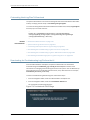
Downloading the Troubleshooting Log File from the UI . . . . . . . . . . . . . . . . . . . . 506
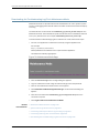
Downloading the Troubleshooting Log File In Maintenance Mode . . . . . . . . . . . 508
Downloading Troubleshooting System Log Files Using the CLI . . . . . . . . . . . . . . 509
Downloading a System Log File Using a USB Device . . . . . . . . . . . . . . . . . . 509
Downloading System Log File Using SCP . . . . . . . . . . . . . . . . . . . . . . . . . . . . 510
xiv
Copyright © 2014, Juniper Networks, Inc.
Table of Contents
Chapter 41
Authentication Servers . . . . . . . . . . . . . . . . . . . . . . . . . . . . . . . . . . . . . . . . . . . . 513
Managing Remote Authentication Servers . . . . . . . . . . . . . . . . . . . . . . . . . . . . . . 513
Remote Authentication Overview . . . . . . . . . . . . . . . . . . . . . . . . . . . . . . . . . . 513
Understanding Junos Space Authentication Modes . . . . . . . . . . . . . . . . . . . 514
Local Authentication . . . . . . . . . . . . . . . . . . . . . . . . . . . . . . . . . . . . . . . . 514
Remote Authentication . . . . . . . . . . . . . . . . . . . . . . . . . . . . . . . . . . . . . . 514
Remote-Local Authentication . . . . . . . . . . . . . . . . . . . . . . . . . . . . . . . . . 514
Managing Remote Authentication Servers . . . . . . . . . . . . . . . . . . . . . . . . . . . 515
Creating a Remote Authentication Server . . . . . . . . . . . . . . . . . . . . . . . . . . . 516
Modifying Authentication Settings . . . . . . . . . . . . . . . . . . . . . . . . . . . . . . . . . 518
Configuring a RADIUS Server for Authentication and Authorization . . . . . . . 519
Configuring TACACS+ for Authentication and Authorization . . . . . . . . . . . . 524
Junos Space Log In Behavior with Remote Authentication Enabled . . . . . . 526
Chapter 42
Managing SMTP Servers . . . . . . . . . . . . . . . . . . . . . . . . . . . . . . . . . . . . . . . . . . 529
Managing Platform SMTP Servers . . . . . . . . . . . . . . . . . . . . . . . . . . . . . . . . . . . . 529
Adding a Platform SMTP Server . . . . . . . . . . . . . . . . . . . . . . . . . . . . . . . . . . . . . . 529
Chapter 43
Managing Tags . . . . . . . . . . . . . . . . . . . . . . . . . . . . . . . . . . . . . . . . . . . . . . . . . . . 531
Overview . . . . . . . . . . . . . . . . . . . . . . . . . . . . . . . . . . . . . . . . . . . . . . . . . . . . . . . . . 531
Managing Tags Overview . . . . . . . . . . . . . . . . . . . . . . . . . . . . . . . . . . . . . . . . . 531
Managing Tags . . . . . . . . . . . . . . . . . . . . . . . . . . . . . . . . . . . . . . . . . . . . . . . . . . . . 532
Managing Tags . . . . . . . . . . . . . . . . . . . . . . . . . . . . . . . . . . . . . . . . . . . . . . . . 532
Managing Hierarchical Tags . . . . . . . . . . . . . . . . . . . . . . . . . . . . . . . . . . . . . . 534
Using the Tag Hierarchy Pane . . . . . . . . . . . . . . . . . . . . . . . . . . . . . . . . . 534
Using the Tabular View Pane . . . . . . . . . . . . . . . . . . . . . . . . . . . . . . . . . . 537
Sharing a Tag . . . . . . . . . . . . . . . . . . . . . . . . . . . . . . . . . . . . . . . . . . . . . . . . . . 537
Renaming Tags . . . . . . . . . . . . . . . . . . . . . . . . . . . . . . . . . . . . . . . . . . . . . . . . 538
Deleting Tags . . . . . . . . . . . . . . . . . . . . . . . . . . . . . . . . . . . . . . . . . . . . . . . . . 539
Tagging an Object . . . . . . . . . . . . . . . . . . . . . . . . . . . . . . . . . . . . . . . . . . . . . . 539
Viewing Tags . . . . . . . . . . . . . . . . . . . . . . . . . . . . . . . . . . . . . . . . . . . . . . . . . . 540
Untagging Objects . . . . . . . . . . . . . . . . . . . . . . . . . . . . . . . . . . . . . . . . . . . . . . 541
Filtering Inventory Using Tags . . . . . . . . . . . . . . . . . . . . . . . . . . . . . . . . . . . . . 541
Creating Tags . . . . . . . . . . . . . . . . . . . . . . . . . . . . . . . . . . . . . . . . . . . . . . . . . . . . . 542
Creating a Tag . . . . . . . . . . . . . . . . . . . . . . . . . . . . . . . . . . . . . . . . . . . . . . . . . 542
Chapter 44
Managing Permission Labels . . . . . . . . . . . . . . . . . . . . . . . . . . . . . . . . . . . . . . 543
Managing Permission Labels Overview . . . . . . . . . . . . . . . . . . . . . . . . . . . . . . . . 543
Working With Permission Labels . . . . . . . . . . . . . . . . . . . . . . . . . . . . . . . . . . . . . . 545
Creating Permission Labels . . . . . . . . . . . . . . . . . . . . . . . . . . . . . . . . . . . . . . 545
Assigning Permission Labels to Users . . . . . . . . . . . . . . . . . . . . . . . . . . . . . . 546
Attaching Permission Labels to Objects . . . . . . . . . . . . . . . . . . . . . . . . . . . . 547
Chapter 45
Managing DMI Schemas . . . . . . . . . . . . . . . . . . . . . . . . . . . . . . . . . . . . . . . . . . 549
Managing DMI Schemas Overview . . . . . . . . . . . . . . . . . . . . . . . . . . . . . . . . . . . . 550
Updating a DMI Schema . . . . . . . . . . . . . . . . . . . . . . . . . . . . . . . . . . . . . . . . . . . . 552
Creating a tgz File for Updating a DMI Schema . . . . . . . . . . . . . . . . . . . . . . . . . . 555
Setting a Default DMI Schema . . . . . . . . . . . . . . . . . . . . . . . . . . . . . . . . . . . . . . . 557
Troubleshooting DMI Schema Management . . . . . . . . . . . . . . . . . . . . . . . . . . . . 558
Copyright © 2014, Juniper Networks, Inc.
xv
Junos Space Network Application Platform User Guide
Part 11
Index
Index . . . . . . . . . . . . . . . . . . . . . . . . . . . . . . . . . . . . . . . . . . . . . . . . . . . . . . . . 563
xvi
Copyright © 2014, Juniper Networks, Inc.
List of Figures
Part 1
Junos Space User Interface
Chapter 1
Getting Started . . . . . . . . . . . . . . . . . . . . . . . . . . . . . . . . . . . . . . . . . . . . . . . . . . . . 3
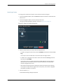
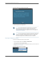
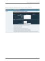
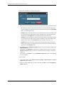
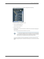
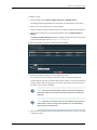
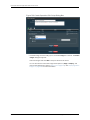
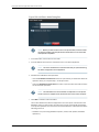
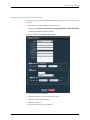
Figure 1: Junos Space System Login Screen . . . . . . . . . . . . . . . . . . . . . . . . . . . . . . . 4
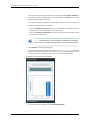
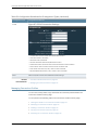
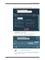
Figure 2: User Preferences Change Local Password . . . . . . . . . . . . . . . . . . . . . . . . . 5
Chapter 2
Understanding the Junos Space User Interface . . . . . . . . . . . . . . . . . . . . . . . . 9
Figure 3: Junos Space Banner . . . . . . . . . . . . . . . . . . . . . . . . . . . . . . . . . . . . . . . . . . 12
Figure 4: Application Chooser . . . . . . . . . . . . . . . . . . . . . . . . . . . . . . . . . . . . . . . . . . 13
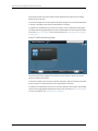
Figure 5: Platform Dashboard . . . . . . . . . . . . . . . . . . . . . . . . . . . . . . . . . . . . . . . . . . 13
Figure 6: Workspace Statistics . . . . . . . . . . . . . . . . . . . . . . . . . . . . . . . . . . . . . . . . . 14
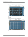
Figure 7: Inventory Page: Thumbnail View . . . . . . . . . . . . . . . . . . . . . . . . . . . . . . . . 15
Figure 8: Inventory Page: Tabular View . . . . . . . . . . . . . . . . . . . . . . . . . . . . . . . . . . 15
Figure 9: Application Chooser . . . . . . . . . . . . . . . . . . . . . . . . . . . . . . . . . . . . . . . . . 16
Figure 10: Application Switcher Menu . . . . . . . . . . . . . . . . . . . . . . . . . . . . . . . . . . . . 17
Figure 11: Navigation Ribbon: Workspaces . . . . . . . . . . . . . . . . . . . . . . . . . . . . . . . . 17
Figure 12: Navigation Ribbon: Tasks . . . . . . . . . . . . . . . . . . . . . . . . . . . . . . . . . . . . . 17
Figure 13: Navigation Ribbon: Subtasks . . . . . . . . . . . . . . . . . . . . . . . . . . . . . . . . . . 18
Figure 14: Platform Application Icon . . . . . . . . . . . . . . . . . . . . . . . . . . . . . . . . . . . . . 18
Figure 15: Platform Dashboard . . . . . . . . . . . . . . . . . . . . . . . . . . . . . . . . . . . . . . . . 20
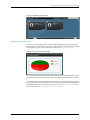
Figure 16: Platform System Health Gadget . . . . . . . . . . . . . . . . . . . . . . . . . . . . . . . 23
Figure 17: Fabric Monitoring Page . . . . . . . . . . . . . . . . . . . . . . . . . . . . . . . . . . . . . . . 24
Figure 18: Manage Users Page . . . . . . . . . . . . . . . . . . . . . . . . . . . . . . . . . . . . . . . . . 25
Figure 19: Job Information Gaget . . . . . . . . . . . . . . . . . . . . . . . . . . . . . . . . . . . . . . . 25
Figure 20: Manage Jobs Page . . . . . . . . . . . . . . . . . . . . . . . . . . . . . . . . . . . . . . . . . 26
Figure 21: Workspace Statistics Pages . . . . . . . . . . . . . . . . . . . . . . . . . . . . . . . . . . . 26
Figure 22: Manage Devices Inventory Page . . . . . . . . . . . . . . . . . . . . . . . . . . . . . . . 27
Figure 23: Manage Devices Page . . . . . . . . . . . . . . . . . . . . . . . . . . . . . . . . . . . . . . . 28
Figure 24: Manage Devices Inventory Page: Thumbnail View . . . . . . . . . . . . . . . . 30
Figure 25: Manage Devices Inventory Page: Tabular View . . . . . . . . . . . . . . . . . . . 30
Figure 26: Sorting Tables . . . . . . . . . . . . . . . . . . . . . . . . . . . . . . . . . . . . . . . . . . . . . 32
Figure 27: Showing or Hiding Columns in Tables . . . . . . . . . . . . . . . . . . . . . . . . . . . 32
Figure 28: Typical Filter Submenu . . . . . . . . . . . . . . . . . . . . . . . . . . . . . . . . . . . . . . 33
Figure 29: Search . . . . . . . . . . . . . . . . . . . . . . . . . . . . . . . . . . . . . . . . . . . . . . . . . . . 33
Figure 30: Page Information Bar . . . . . . . . . . . . . . . . . . . . . . . . . . . . . . . . . . . . . . . 34
Figure 31: Typical Submenu for a Date Column . . . . . . . . . . . . . . . . . . . . . . . . . . . . 36
Figure 32: Typical Submenu for a Text Column . . . . . . . . . . . . . . . . . . . . . . . . . . . . 36
Figure 33: Typical Submenu for a Column of Discrete Elements . . . . . . . . . . . . . . 37
Figure 34: Typical Submenu for a Column of Numerical Values . . . . . . . . . . . . . . . 37
Copyright © 2014, Juniper Networks, Inc.
xvii
Junos Space Network Application Platform User Guide
Part 2
Devices
Chapter 3
Discovering Devices . . . . . . . . . . . . . . . . . . . . . . . . . . . . . . . . . . . . . . . . . . . . . . . . 41
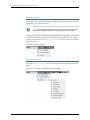
Figure 35: Specify Probes Dialog Box . . . . . . . . . . . . . . . . . . . . . . . . . . . . . . . . . . . 45
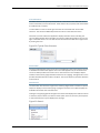
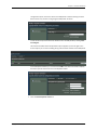
Figure 36: Add SNMP Settings Dialog Box (SNMP V1/V2C) . . . . . . . . . . . . . . . . . 46
Figure 37: Add SNMP Settings Dialog Box (SNMP V3) . . . . . . . . . . . . . . . . . . . . . 46
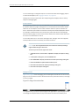
Figure 38: Specify Credentials Dialog Box . . . . . . . . . . . . . . . . . . . . . . . . . . . . . . . . 47
Figure 39: Add Device Login Credential . . . . . . . . . . . . . . . . . . . . . . . . . . . . . . . . . . 47
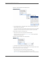
Figure 40: Discovery Status Report . . . . . . . . . . . . . . . . . . . . . . . . . . . . . . . . . . . . . 48
Figure 41: Device Discovery Detailed Report . . . . . . . . . . . . . . . . . . . . . . . . . . . . . . 49
Figure 42: Job Report: Discover Network Elements Job . . . . . . . . . . . . . . . . . . . . . 49
Chapter 4
Adding Deployed Devices . . . . . . . . . . . . . . . . . . . . . . . . . . . . . . . . . . . . . . . . . . . 51
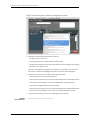
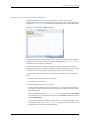
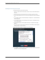
Figure 43: Selecting a CSV File to Upload . . . . . . . . . . . . . . . . . . . . . . . . . . . . . . . . 53
Chapter 5
Device Management Overview . . . . . . . . . . . . . . . . . . . . . . . . . . . . . . . . . . . . . . 57
Figure 44: Device Count by Platform Report . . . . . . . . . . . . . . . . . . . . . . . . . . . . . . 59
Figure 45: Device Status Report . . . . . . . . . . . . . . . . . . . . . . . . . . . . . . . . . . . . . . . 60
Figure 46: Device Count by OS Report . . . . . . . . . . . . . . . . . . . . . . . . . . . . . . . . . . . 61
Chapter 6
Managing Devices . . . . . . . . . . . . . . . . . . . . . . . . . . . . . . . . . . . . . . . . . . . . . . . . . 63
Figure 47: Inventory Page: SRX Chassis Cluster . . . . . . . . . . . . . . . . . . . . . . . . . . . 65
Figure 48: Table Icon . . . . . . . . . . . . . . . . . . . . . . . . . . . . . . . . . . . . . . . . . . . . . . . . 65
Figure 49: Device Table . . . . . . . . . . . . . . . . . . . . . . . . . . . . . . . . . . . . . . . . . . . . . . 66
Figure 50: Selecting Columns . . . . . . . . . . . . . . . . . . . . . . . . . . . . . . . . . . . . . . . . . 67
Figure 51: Device Inventory: Single Chassis . . . . . . . . . . . . . . . . . . . . . . . . . . . . . . . 76
Figure 52: Device Inventory: Chassis Cluster . . . . . . . . . . . . . . . . . . . . . . . . . . . . . . 76
Figure 53: Device Inventory: Service Information . . . . . . . . . . . . . . . . . . . . . . . . . . 76
Figure 54: Device Inventory: Physical Interfaces . . . . . . . . . . . . . . . . . . . . . . . . . . . 78
Figure 55: Logical Interface Inventory Table . . . . . . . . . . . . . . . . . . . . . . . . . . . . . . 80
Figure 56: Delete Devices Dialog Box . . . . . . . . . . . . . . . . . . . . . . . . . . . . . . . . . . . 82
Figure 57: Resynchronize Devices Dialog Box . . . . . . . . . . . . . . . . . . . . . . . . . . . . . 83
Figure 58: Resynchronization Information Status Message . . . . . . . . . . . . . . . . . . 83
Figure 59: Change Credentials Dialog Box . . . . . . . . . . . . . . . . . . . . . . . . . . . . . . . 85
Figure 60: Change Credentials Dialog Box . . . . . . . . . . . . . . . . . . . . . . . . . . . . . . . 85
Figure 61: Physical Inventory with Service Contract Data . . . . . . . . . . . . . . . . . . . . 86
Figure 62: Physical Inventory with Column Display Filters . . . . . . . . . . . . . . . . . . . 87
Figure 63: Service Now Service Detail Page . . . . . . . . . . . . . . . . . . . . . . . . . . . . . . 88
Figure 64: Service Insight Exposure Analyzer Record with EOL Data . . . . . . . . . . 89
Figure 65: Manage Devices Inventory Table . . . . . . . . . . . . . . . . . . . . . . . . . . . . . . 90
Figure 66: Manage Devices Actions Drawer . . . . . . . . . . . . . . . . . . . . . . . . . . . . . . 90
Figure 67: Physical Inventory View . . . . . . . . . . . . . . . . . . . . . . . . . . . . . . . . . . . . . . 91
Figure 68: Physical Inventory View with Expanded Details . . . . . . . . . . . . . . . . . . . 91
Figure 69: Export Inventory Dialog Box . . . . . . . . . . . . . . . . . . . . . . . . . . . . . . . . . . 92
Figure 70: Export Inventory Job Status Report . . . . . . . . . . . . . . . . . . . . . . . . . . . . 92
Figure 71: QuickView Sidebar Arrow (Highlighted in Green) . . . . . . . . . . . . . . . . . . 96
Figure 72: Typical QuickView Icon Elements . . . . . . . . . . . . . . . . . . . . . . . . . . . . . . 97
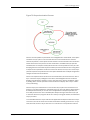
Figure 73: Resynchronization Process . . . . . . . . . . . . . . . . . . . . . . . . . . . . . . . . . . . 113
Chapter 7
Adding Devices and Connection Profiles . . . . . . . . . . . . . . . . . . . . . . . . . . . . . 115
Figure 74: Deploy Devices Inventory . . . . . . . . . . . . . . . . . . . . . . . . . . . . . . . . . . . . 118
xviii
Copyright © 2014, Juniper Networks, Inc.
List of Figures
Figure 75: Device Details dialog box . . . . . . . . . . . . . . . . . . . . . . . . . . . . . . . . . . . . 118
Figure 76: Selecting a CSV File to Upload . . . . . . . . . . . . . . . . . . . . . . . . . . . . . . . . 119
Figure 77: Specifying Device Details . . . . . . . . . . . . . . . . . . . . . . . . . . . . . . . . . . . . 120
Figure 78: Specifying Connectivity Details . . . . . . . . . . . . . . . . . . . . . . . . . . . . . . . 120
Figure 79: Specifying Configlet Options . . . . . . . . . . . . . . . . . . . . . . . . . . . . . . . . . 123
Figure 80: Deployment Instance Details Report . . . . . . . . . . . . . . . . . . . . . . . . . . 124
Figure 81: Delete Deployment Instance Dialog Box . . . . . . . . . . . . . . . . . . . . . . . . 125
Figure 82: Download Configlets Dialog Box . . . . . . . . . . . . . . . . . . . . . . . . . . . . . . 126
Figure 83: Searching for a Configlet . . . . . . . . . . . . . . . . . . . . . . . . . . . . . . . . . . . . 126
Figure 84: Connection Profiles Inventory . . . . . . . . . . . . . . . . . . . . . . . . . . . . . . . . 129
Figure 85: Creating a Connection Profile . . . . . . . . . . . . . . . . . . . . . . . . . . . . . . . . 129
Figure 86: PPPoA Connection Settings . . . . . . . . . . . . . . . . . . . . . . . . . . . . . . . . . . 131
Figure 87: PPPoE Connection Settings . . . . . . . . . . . . . . . . . . . . . . . . . . . . . . . . . . 132
Figure 88: Viewing the Details of a Connection Profile . . . . . . . . . . . . . . . . . . . . . 133
Figure 89: Modifying a Connection Profile . . . . . . . . . . . . . . . . . . . . . . . . . . . . . . . 134
Figure 90: Searching for a Connection Profile . . . . . . . . . . . . . . . . . . . . . . . . . . . . 135
Chapter 8
Secure Console . . . . . . . . . . . . . . . . . . . . . . . . . . . . . . . . . . . . . . . . . . . . . . . . . . . 137
Figure 91: Verifying the Device Key Fingerprint . . . . . . . . . . . . . . . . . . . . . . . . . . . . 138
Figure 92: Logging Into the Device after Validating the Fingerprint . . . . . . . . . . . 139
Figure 93: Secure Console Dialog Box . . . . . . . . . . . . . . . . . . . . . . . . . . . . . . . . . . 140
Figure 94: Validating the Server Key Fingerprint . . . . . . . . . . . . . . . . . . . . . . . . . . . 141
Figure 95: SSH Connection after Validating Server Key Fingerprint . . . . . . . . . . . 141
Figure 96: Validating the Server Key Fingerprint . . . . . . . . . . . . . . . . . . . . . . . . . . 143
Chapter 9
Device Adapters . . . . . . . . . . . . . . . . . . . . . . . . . . . . . . . . . . . . . . . . . . . . . . . . . 149
Figure 97: Add Adapter Dialog Box . . . . . . . . . . . . . . . . . . . . . . . . . . . . . . . . . . . . . 150
Figure 98: Modify Application Settings Page . . . . . . . . . . . . . . . . . . . . . . . . . . . . . 152
Chapter 10
Discovering Topologies . . . . . . . . . . . . . . . . . . . . . . . . . . . . . . . . . . . . . . . . . . . . 155
Figure 99: Discover Topology . . . . . . . . . . . . . . . . . . . . . . . . . . . . . . . . . . . . . . . . . 156
Figure 100: Discovery Job Details Report . . . . . . . . . . . . . . . . . . . . . . . . . . . . . . . . 157
Figure 101: Specify Device Targets . . . . . . . . . . . . . . . . . . . . . . . . . . . . . . . . . . . . . 158
Figure 102: Specify SNMP Probes . . . . . . . . . . . . . . . . . . . . . . . . . . . . . . . . . . . . . 159
Figure 103: Add Device Target Dialog Box . . . . . . . . . . . . . . . . . . . . . . . . . . . . . . . 160
Figure 104: Add SNMP V1/V2C Settings Dialog Box . . . . . . . . . . . . . . . . . . . . . . . 162
Figure 105: Add SNMP V3 Settings Dialog Box . . . . . . . . . . . . . . . . . . . . . . . . . . . 162
Part 3
Device Templates
Chapter 11
Overview . . . . . . . . . . . . . . . . . . . . . . . . . . . . . . . . . . . . . . . . . . . . . . . . . . . . . . . . 167
Figure 106: Workflow for Device Template Definition and Template Creation . . . 170
Figure 107: Device Templates Statistics Page . . . . . . . . . . . . . . . . . . . . . . . . . . . . . 171
Chapter 12
Template Definitions . . . . . . . . . . . . . . . . . . . . . . . . . . . . . . . . . . . . . . . . . . . . . . 173
Figure 108: Unpublish Template Definition . . . . . . . . . . . . . . . . . . . . . . . . . . . . . . 175
Figure 109: Template Definition Workflow . . . . . . . . . . . . . . . . . . . . . . . . . . . . . . . 181
Figure 110: Create Definition Page . . . . . . . . . . . . . . . . . . . . . . . . . . . . . . . . . . . . . 183
Figure 111: Create Definition Dialog Box . . . . . . . . . . . . . . . . . . . . . . . . . . . . . . . . . 184
Figure 112: Information Icon Pop-Up in the Template . . . . . . . . . . . . . . . . . . . . . . 189
Figure 113: Specify Default Values Page . . . . . . . . . . . . . . . . . . . . . . . . . . . . . . . . . 195
Copyright © 2014, Juniper Networks, Inc.
xix
Junos Space Network Application Platform User Guide
Figure 114: Specify Default Values Page . . . . . . . . . . . . . . . . . . . . . . . . . . . . . . . . . 195
Figure 115: Browsing the Available Configuration Hierarchy . . . . . . . . . . . . . . . . . 197
Figure 116: Searching for a Specific Configuration Option . . . . . . . . . . . . . . . . . . . 198
Figure 117: CSV File for SNMP Contact . . . . . . . . . . . . . . . . . . . . . . . . . . . . . . . . . . 199
Chapter 13
Templates . . . . . . . . . . . . . . . . . . . . . . . . . . . . . . . . . . . . . . . . . . . . . . . . . . . . . . 207
Figure 118: Template Status Report . . . . . . . . . . . . . . . . . . . . . . . . . . . . . . . . . . . . 208
Figure 119: Device Templates Statistics Page . . . . . . . . . . . . . . . . . . . . . . . . . . . . 222
Chapter 14
Troubleshooting . . . . . . . . . . . . . . . . . . . . . . . . . . . . . . . . . . . . . . . . . . . . . . . . . 223
Figure 120: My Jobs Report . . . . . . . . . . . . . . . . . . . . . . . . . . . . . . . . . . . . . . . . . . . 225
Part 4
Device Images and Scripts
Chapter 17
Scripts . . . . . . . . . . . . . . . . . . . . . . . . . . . . . . . . . . . . . . . . . . . . . . . . . . . . . . . . . . 237
Figure 121: Manage Scripts page . . . . . . . . . . . . . . . . . . . . . . . . . . . . . . . . . . . . . . 238
Chapter 19
Script Bundles . . . . . . . . . . . . . . . . . . . . . . . . . . . . . . . . . . . . . . . . . . . . . . . . . . . 243
Figure 122: Manage Script Bundles Page . . . . . . . . . . . . . . . . . . . . . . . . . . . . . . . . 243
Chapter 20
Configuration: Device Images . . . . . . . . . . . . . . . . . . . . . . . . . . . . . . . . . . . . . . 245
Figure 123: Upload Image Dialog Box . . . . . . . . . . . . . . . . . . . . . . . . . . . . . . . . . . 245
Figure 124: Validation Results Page . . . . . . . . . . . . . . . . . . . . . . . . . . . . . . . . . . . . 249
Figure 125: View Deploy Results Page . . . . . . . . . . . . . . . . . . . . . . . . . . . . . . . . . . 255
Figure 126: Modify Device Image Details . . . . . . . . . . . . . . . . . . . . . . . . . . . . . . . . 257
Chapter 21
Configuration: Scripts . . . . . . . . . . . . . . . . . . . . . . . . . . . . . . . . . . . . . . . . . . . . 259
Figure 127: Import Scripts Dialog Box . . . . . . . . . . . . . . . . . . . . . . . . . . . . . . . . . . 260
Figure 128: Modify Script Dialog Box . . . . . . . . . . . . . . . . . . . . . . . . . . . . . . . . . . . 261
Figure 129: Compare Scripts Dialog Box . . . . . . . . . . . . . . . . . . . . . . . . . . . . . . . . 262
Figure 130: Compare Scripts Window . . . . . . . . . . . . . . . . . . . . . . . . . . . . . . . . . . 263
Figure 131: Delete Device Scripts Dialog Box . . . . . . . . . . . . . . . . . . . . . . . . . . . . . 264
Figure 132: Deploy Scripts On Device(s) Dialog Box . . . . . . . . . . . . . . . . . . . . . . . 265
Figure 133: Verify Checksum of Scripts on Device(s) Dialog Box . . . . . . . . . . . . . 267
Figure 134: Enable Scripts on Device(s) Dialog Box . . . . . . . . . . . . . . . . . . . . . . . 268
Figure 135: Execute Script on Device(s) Dialog Box . . . . . . . . . . . . . . . . . . . . . . . 270
Chapter 22
Configuration: Operations . . . . . . . . . . . . . . . . . . . . . . . . . . . . . . . . . . . . . . . . . 273
Figure 136: Create Operation-Edit Script Dialog Box . . . . . . . . . . . . . . . . . . . . . . . 274
Figure 137: Create Operation-Edit Image Dialog Box . . . . . . . . . . . . . . . . . . . . . . . 275
Figure 138: Create Operation-Add Operation Dialog Box . . . . . . . . . . . . . . . . . . . 275
Figure 139: Run Operation Page . . . . . . . . . . . . . . . . . . . . . . . . . . . . . . . . . . . . . . . 278
Chapter 23
Configuration: Script Bundles . . . . . . . . . . . . . . . . . . . . . . . . . . . . . . . . . . . . . . 281
Figure 140: Create Script Bundle page . . . . . . . . . . . . . . . . . . . . . . . . . . . . . . . . . . 281
Figure 141: Modify Script Bundle page . . . . . . . . . . . . . . . . . . . . . . . . . . . . . . . . . . 283
Figure 142: Deploy Script Bundle On Device(s) Dialog Box . . . . . . . . . . . . . . . . . 285
Figure 143: Execute Script Bundle On Devices(s) Dialog Box . . . . . . . . . . . . . . . . 286
Chapter 24
Administration: Scripts . . . . . . . . . . . . . . . . . . . . . . . . . . . . . . . . . . . . . . . . . . . 289
Figure 144: Script Details Dialog Box . . . . . . . . . . . . . . . . . . . . . . . . . . . . . . . . . . . 290
Figure 145: Script Verification Results Dialog Box . . . . . . . . . . . . . . . . . . . . . . . . . 291
xx
Copyright © 2014, Juniper Networks, Inc.
List of Figures
Chapter 25
Administration: Operations . . . . . . . . . . . . . . . . . . . . . . . . . . . . . . . . . . . . . . . 293
Figure 146: View Operation Results Page . . . . . . . . . . . . . . . . . . . . . . . . . . . . . . . 294
Part 7
Job Management
Chapter 29
Operation . . . . . . . . . . . . . . . . . . . . . . . . . . . . . . . . . . . . . . . . . . . . . . . . . . . . . . . 361
Figure 147: My Jobs Report . . . . . . . . . . . . . . . . . . . . . . . . . . . . . . . . . . . . . . . . . . . 362
Figure 148: Recurring Database Job . . . . . . . . . . . . . . . . . . . . . . . . . . . . . . . . . . . . 363
Figure 149: Recurrence Entry in Manage Jobs Table . . . . . . . . . . . . . . . . . . . . . . . 364
Part 8
Audit Logs
Chapter 31
Operation . . . . . . . . . . . . . . . . . . . . . . . . . . . . . . . . . . . . . . . . . . . . . . . . . . . . . . . 375
Figure 150: Formatting the Local Times Column in Microsoft Excel . . . . . . . . . . 380
Part 9
Users
Chapter 33
User Accounts . . . . . . . . . . . . . . . . . . . . . . . . . . . . . . . . . . . . . . . . . . . . . . . . . . . 407
Figure 151: CreateUser36138.gif . . . . . . . . . . . . . . . . . . . . . . . . . . . . . . . . . . . . . . . 408
Figure 152: User Preferences Change Local Password . . . . . . . . . . . . . . . . . . . . . 415
Part 10
Administration
Chapter 35
Overview . . . . . . . . . . . . . . . . . . . . . . . . . . . . . . . . . . . . . . . . . . . . . . . . . . . . . . . . 427
Figure 153: Maintenance Mode Actions Menu . . . . . . . . . . . . . . . . . . . . . . . . . . . 429
Chapter 36
Fabric . . . . . . . . . . . . . . . . . . . . . . . . . . . . . . . . . . . . . . . . . . . . . . . . . . . . . . . . . . . 431
Figure 154: Fabric Nodes . . . . . . . . . . . . . . . . . . . . . . . . . . . . . . . . . . . . . . . . . . . . 432
Figure 155: Fabric with One Node . . . . . . . . . . . . . . . . . . . . . . . . . . . . . . . . . . . . . 433
Figure 156: Fabric with Two Nodes . . . . . . . . . . . . . . . . . . . . . . . . . . . . . . . . . . . . 434
Figure 157: Fabric with Three Nodes . . . . . . . . . . . . . . . . . . . . . . . . . . . . . . . . . . . 434
Figure 158: Add Fabric Node Dialog Box . . . . . . . . . . . . . . . . . . . . . . . . . . . . . . . . 436
Figure 159: Virtual Appliance Icons . . . . . . . . . . . . . . . . . . . . . . . . . . . . . . . . . . . . 439
Figure 160: Overall System Condition Gauge . . . . . . . . . . . . . . . . . . . . . . . . . . . . 449
Figure 161: Fabric Load History Chart . . . . . . . . . . . . . . . . . . . . . . . . . . . . . . . . . . 450
Chapter 37
Manage Databases . . . . . . . . . . . . . . . . . . . . . . . . . . . . . . . . . . . . . . . . . . . . . . . 461
Figure 162: Backup Database Dialog Box . . . . . . . . . . . . . . . . . . . . . . . . . . . . . . . 465
Figure 163: Maintenance Mode Dialog Box . . . . . . . . . . . . . . . . . . . . . . . . . . . . . . . 471
Figure 164: Authentication Required Dialog Box . . . . . . . . . . . . . . . . . . . . . . . . . . 471
Figure 165: Maintenance Actions . . . . . . . . . . . . . . . . . . . . . . . . . . . . . . . . . . . . . . 472
Figure 166: Selection Box . . . . . . . . . . . . . . . . . . . . . . . . . . . . . . . . . . . . . . . . . . . . 472
Figure 167: Confirmation Message . . . . . . . . . . . . . . . . . . . . . . . . . . . . . . . . . . . . . 472
Chapter 38
Manage Licenses . . . . . . . . . . . . . . . . . . . . . . . . . . . . . . . . . . . . . . . . . . . . . . . . . 477
Figure 168: Administration: Upload Licence Dialog Box . . . . . . . . . . . . . . . . . . . . 478
Figure 169: License Information Upload Success Message . . . . . . . . . . . . . . . . . 479
Figure 170: Manage Licenses Inventory Page . . . . . . . . . . . . . . . . . . . . . . . . . . . . 479
Figure 171: License File . . . . . . . . . . . . . . . . . . . . . . . . . . . . . . . . . . . . . . . . . . . . . . . 481
Chapter 39
Manage Applications . . . . . . . . . . . . . . . . . . . . . . . . . . . . . . . . . . . . . . . . . . . . . 483
Copyright © 2014, Juniper Networks, Inc.
xxi
Junos Space Network Application Platform User Guide
Figure 172: Modify Network Application Platform Settings . . . . . . . . . . . . . . . . . 490
Chapter 40
System Troubleshooting . . . . . . . . . . . . . . . . . . . . . . . . . . . . . . . . . . . . . . . . . . 503
Figure 173: Troubleshoot SPACE Page . . . . . . . . . . . . . . . . . . . . . . . . . . . . . . . . . 506
Figure 174: Maintenance Mode Page . . . . . . . . . . . . . . . . . . . . . . . . . . . . . . . . . . . 508
xxii
Copyright © 2014, Juniper Networks, Inc.
List of Tables
About the Documentation . . . . . . . . . . . . . . . . . . . . . . . . . . . . . . . . . . . . . . . . xxvii
Table 1: Notice Icons . . . . . . . . . . . . . . . . . . . . . . . . . . . . . . . . . . . . . . . . . . . . . . . xxviii
Table 2: Text and Syntax Conventions . . . . . . . . . . . . . . . . . . . . . . . . . . . . . . . . . xxviii
Part 1
Junos Space User Interface
Chapter 2
Understanding the Junos Space User Interface . . . . . . . . . . . . . . . . . . . . . . . . 9
Table 3: Junos Space Application Icons . . . . . . . . . . . . . . . . . . . . . . . . . . . . . . . . . . 10
Table 4: Junos Space Shortcut Icons . . . . . . . . . . . . . . . . . . . . . . . . . . . . . . . . . . . . 11
Table 5: Global Action Icons . . . . . . . . . . . . . . . . . . . . . . . . . . . . . . . . . . . . . . . . . . . 12
Table 6: Workspace Icons . . . . . . . . . . . . . . . . . . . . . . . . . . . . . . . . . . . . . . . . . . . . 20
Table 7: Gadget Mouse-Over and Double-Click Operations . . . . . . . . . . . . . . . . . . 22
Table 8: Table Paging and Refreshing Controls . . . . . . . . . . . . . . . . . . . . . . . . . . . . 35
Part 2
Devices
Chapter 4
Adding Deployed Devices . . . . . . . . . . . . . . . . . . . . . . . . . . . . . . . . . . . . . . . . . . . 51
Table 9: Icons to View or Download Management CLI Commands . . . . . . . . . . . . 54
Chapter 6
Managing Devices . . . . . . . . . . . . . . . . . . . . . . . . . . . . . . . . . . . . . . . . . . . . . . . . . 63
Table 10: Device Connection Status Icon . . . . . . . . . . . . . . . . . . . . . . . . . . . . . . . . 64
Table 11: Fields in the Manage Devices Table . . . . . . . . . . . . . . . . . . . . . . . . . . . . . 66
Table 12: Device Inventory Fields . . . . . . . . . . . . . . . . . . . . . . . . . . . . . . . . . . . . . . . 77
Table 13: Physical Interfaces Columns . . . . . . . . . . . . . . . . . . . . . . . . . . . . . . . . . . . 79
Table 14: Logical Interfaces Columns . . . . . . . . . . . . . . . . . . . . . . . . . . . . . . . . . . . 80
Table 15: Software Inventory Fields . . . . . . . . . . . . . . . . . . . . . . . . . . . . . . . . . . . . . 94
Table 16: License Usage Summary Fields . . . . . . . . . . . . . . . . . . . . . . . . . . . . . . . 102
Table 17: License Feature or SKU Fields . . . . . . . . . . . . . . . . . . . . . . . . . . . . . . . . . 103
Table 18: Additional Fields in CSV Files . . . . . . . . . . . . . . . . . . . . . . . . . . . . . . . . . 103
Table 19: Commands Available in the Troubleshoot Device Dialog Box . . . . . . . . 110
Chapter 7
Adding Devices and Connection Profiles . . . . . . . . . . . . . . . . . . . . . . . . . . . . . 115
Table 20: Icons in the Rapid Deployment dialog box . . . . . . . . . . . . . . . . . . . . . . . 122
Table 21: Fields Manually Entered in the Rapid Deployment Dialog Box . . . . . . . . 123
Table 22: Configuration Guidelines for IP Assignment Types . . . . . . . . . . . . . . . . 130
Chapter 10
Discovering Topologies . . . . . . . . . . . . . . . . . . . . . . . . . . . . . . . . . . . . . . . . . . . . 155
Table 23: Discover Topology Landing Page Field Name and Descriptions . . . . . . 156
Table 24: Discovery Job Details Field Names and Descriptions . . . . . . . . . . . . . . . 157
Part 3
Device Templates
Chapter 12
Template Definitions . . . . . . . . . . . . . . . . . . . . . . . . . . . . . . . . . . . . . . . . . . . . . . 173
Copyright © 2014, Juniper Networks, Inc.
xxiii
Junos Space Network Application Platform User Guide
Table 25: Template Definition States . . . . . . . . . . . . . . . . . . . . . . . . . . . . . . . . . . . 174
Table 26: Data Types and Tabs . . . . . . . . . . . . . . . . . . . . . . . . . . . . . . . . . . . . . . . 186
Table 27: Data Types and Validation Parameters . . . . . . . . . . . . . . . . . . . . . . . . . 186
Table 28: CSV File for Interfaces . . . . . . . . . . . . . . . . . . . . . . . . . . . . . . . . . . . . . . 200
Chapter 13
Templates . . . . . . . . . . . . . . . . . . . . . . . . . . . . . . . . . . . . . . . . . . . . . . . . . . . . . . 207
Table 29: Device Template State Icon Indicators . . . . . . . . . . . . . . . . . . . . . . . . . 208
Table 30: Descriptive Information . . . . . . . . . . . . . . . . . . . . . . . . . . . . . . . . . . . . . 209
Table 31: Review Changes Page . . . . . . . . . . . . . . . . . . . . . . . . . . . . . . . . . . . . . . . 215
Table 32: View Deployment Table . . . . . . . . . . . . . . . . . . . . . . . . . . . . . . . . . . . . . 217
Chapter 14
Troubleshooting . . . . . . . . . . . . . . . . . . . . . . . . . . . . . . . . . . . . . . . . . . . . . . . . . 223
Table 33: Detailed Audit Logs Information and View Audit Log Table
Columns . . . . . . . . . . . . . . . . . . . . . . . . . . . . . . . . . . . . . . . . . . . . . . . . . . . . . 224
Table 34: Audit Log Table Details for Recurring and Non-recurring Jobs . . . . . . . 224
Part 4
Device Images and Scripts
Chapter 15
Overview . . . . . . . . . . . . . . . . . . . . . . . . . . . . . . . . . . . . . . . . . . . . . . . . . . . . . . . . 231
Table 35: Device Images and Scripts User Roles . . . . . . . . . . . . . . . . . . . . . . . . . . 232
Chapter 16
Device Images . . . . . . . . . . . . . . . . . . . . . . . . . . . . . . . . . . . . . . . . . . . . . . . . . . . 235
Table 36: Manage Images Page . . . . . . . . . . . . . . . . . . . . . . . . . . . . . . . . . . . . . . . 235
Chapter 17
Scripts . . . . . . . . . . . . . . . . . . . . . . . . . . . . . . . . . . . . . . . . . . . . . . . . . . . . . . . . . . 237
Table 37: Manage Scripts Page Fields Description . . . . . . . . . . . . . . . . . . . . . . . . 238
Chapter 20
Configuration: Device Images . . . . . . . . . . . . . . . . . . . . . . . . . . . . . . . . . . . . . . 245
Table 38: Stage Image On Devices Dialog Box Fields Descriptions . . . . . . . . . . . 247
Table 39: Validation Results Page Field Descriptions . . . . . . . . . . . . . . . . . . . . . . 249
Table 40: Routing Platforms and Software Releases Supporting ISSU . . . . . . . 250
Table 41: Common Deployment Options Description . . . . . . . . . . . . . . . . . . . . . . 253
Table 42: Conventional Deployment Options Description . . . . . . . . . . . . . . . . . . 253
Table 43: ISSU Deployment Options Description . . . . . . . . . . . . . . . . . . . . . . . . . 253
Table 44: Advanced Deployment Options Description . . . . . . . . . . . . . . . . . . . . 254
Table 45: Select Devices Table Field Descriptions . . . . . . . . . . . . . . . . . . . . . . . . 254
Chapter 22
Configuration: Operations . . . . . . . . . . . . . . . . . . . . . . . . . . . . . . . . . . . . . . . . . 273
Table 46: Create Operation Dialog Box Icon Descriptions . . . . . . . . . . . . . . . . . . 276
Chapter 23
Configuration: Script Bundles . . . . . . . . . . . . . . . . . . . . . . . . . . . . . . . . . . . . . . 281
Table 47: Create Script Bundle Dialog Box Icon Descriptions . . . . . . . . . . . . . . . . 282
Table 48: Modify Script Bundle Dialog Box Icon Descriptions . . . . . . . . . . . . . . . 283
Chapter 24
Administration: Scripts . . . . . . . . . . . . . . . . . . . . . . . . . . . . . . . . . . . . . . . . . . . 289
Table 49: Script Details Dialog Box Fields . . . . . . . . . . . . . . . . . . . . . . . . . . . . . . 290
Table 50: Script Verification Results Page Fields . . . . . . . . . . . . . . . . . . . . . . . . . . 291
Part 5
Network Monitoring
Chapter 26
Network Monitoring UI . . . . . . . . . . . . . . . . . . . . . . . . . . . . . . . . . . . . . . . . . . . . 297
Table 51: Alarms Table . . . . . . . . . . . . . . . . . . . . . . . . . . . . . . . . . . . . . . . . . . . . . . 304
Table 52: Notifications Table . . . . . . . . . . . . . . . . . . . . . . . . . . . . . . . . . . . . . . . . . 305
xxiv
Copyright © 2014, Juniper Networks, Inc.
List of Tables
Table 53: Node Status Table . . . . . . . . . . . . . . . . . . . . . . . . . . . . . . . . . . . . . . . . . 305
Table 54: Resource Graphs Table . . . . . . . . . . . . . . . . . . . . . . . . . . . . . . . . . . . . . 305
Table 55: Information Displayed in the Alarms List . . . . . . . . . . . . . . . . . . . . . . . . 312
Part 7
Job Management
Chapter 28
Overview . . . . . . . . . . . . . . . . . . . . . . . . . . . . . . . . . . . . . . . . . . . . . . . . . . . . . . . . 357
Table 56: Junos Space Job Types Per Application . . . . . . . . . . . . . . . . . . . . . . . . 358
Chapter 29
Operation . . . . . . . . . . . . . . . . . . . . . . . . . . . . . . . . . . . . . . . . . . . . . . . . . . . . . . . 361
Table 57: Job Icon Status Indicators . . . . . . . . . . . . . . . . . . . . . . . . . . . . . . . . . . . 364
Table 58: Job Details and Columns in the Manage Jobs Table . . . . . . . . . . . . . . . 365
Part 8
Audit Logs
Chapter 31
Operation . . . . . . . . . . . . . . . . . . . . . . . . . . . . . . . . . . . . . . . . . . . . . . . . . . . . . . . 375
Table 59: Detailed Audit Logs Information and View Audit Log Table
Columns . . . . . . . . . . . . . . . . . . . . . . . . . . . . . . . . . . . . . . . . . . . . . . . . . . . . . 376
Table 60: Audit Log Table Details for Recurring and Non-recurring Jobs . . . . . . . 376
Part 9
Users
Chapter 32
Role-Based Access Control . . . . . . . . . . . . . . . . . . . . . . . . . . . . . . . . . . . . . . . . 387
Table 61: Predefined Roles for the Network Application Platform . . . . . . . . . . . . 390
Table 62: Predefined Roles for Network Activate Application . . . . . . . . . . . . . . . 397
Table 63: Predefined Roles for Service Insight Application . . . . . . . . . . . . . . . . . 398
Table 64: Predefined Roles for Service Now Application . . . . . . . . . . . . . . . . . . 400
Table 65: Predefined Roles for Ethernet Design Application . . . . . . . . . . . . . . . . 404
Chapter 33
User Accounts . . . . . . . . . . . . . . . . . . . . . . . . . . . . . . . . . . . . . . . . . . . . . . . . . . . 407
Table 66: Users Detailed Information and Columns in the Manage Users
Table . . . . . . . . . . . . . . . . . . . . . . . . . . . . . . . . . . . . . . . . . . . . . . . . . . . . . . . . . 412
Part 10
Administration
Chapter 35
Overview . . . . . . . . . . . . . . . . . . . . . . . . . . . . . . . . . . . . . . . . . . . . . . . . . . . . . . . . 427
Table 67: Junos Space Administrators . . . . . . . . . . . . . . . . . . . . . . . . . . . . . . . . . . 427
Chapter 36
Fabric . . . . . . . . . . . . . . . . . . . . . . . . . . . . . . . . . . . . . . . . . . . . . . . . . . . . . . . . . . . 431
Table 68: Fields for the Fabric Monitoring Inventory Page . . . . . . . . . . . . . . . . . . 439
Table 69: Logical Component Monitoring . . . . . . . . . . . . . . . . . . . . . . . . . . . . . . . 451
Chapter 37
Manage Databases . . . . . . . . . . . . . . . . . . . . . . . . . . . . . . . . . . . . . . . . . . . . . . . 461
Table 70: Backup Schedule Units and Increments . . . . . . . . . . . . . . . . . . . . . . . . 464
Table 71: Fields in the Manage Databases Table . . . . . . . . . . . . . . . . . . . . . . . . . . 473
Chapter 38
Manage Licenses . . . . . . . . . . . . . . . . . . . . . . . . . . . . . . . . . . . . . . . . . . . . . . . . . 477
Table 72: Manage Licenses Details . . . . . . . . . . . . . . . . . . . . . . . . . . . . . . . . . . . . 481
Chapter 39
Manage Applications . . . . . . . . . . . . . . . . . . . . . . . . . . . . . . . . . . . . . . . . . . . . . 483
Table 73: Application Information . . . . . . . . . . . . . . . . . . . . . . . . . . . . . . . . . . . . . 486
Table 74: Network Application Platform Application Settings . . . . . . . . . . . . . . 488
Copyright © 2014, Juniper Networks, Inc.
xxv
Junos Space Network Application Platform User Guide
Table 75: Password Constraint Parameters . . . . . . . . . . . . . . . . . . . . . . . . . . . . . 490
Table 76: Network Activate Application Settings . . . . . . . . . . . . . . . . . . . . . . . . . 492
Chapter 40
System Troubleshooting . . . . . . . . . . . . . . . . . . . . . . . . . . . . . . . . . . . . . . . . . . 503
Table 77: Log Files included in the troubleshoot File . . . . . . . . . . . . . . . . . . . . . . 504
Table 78: Data and Log Files in troubleshoot.zip File . . . . . . . . . . . . . . . . . . . . . . 507
Chapter 41
Authentication Servers . . . . . . . . . . . . . . . . . . . . . . . . . . . . . . . . . . . . . . . . . . . . 513
Table 79: Remote Authentication Server Settings . . . . . . . . . . . . . . . . . . . . . . . . . 517
Table 80: TACACS+ Remote Authentication Server Settings . . . . . . . . . . . . . . . 524
Chapter 43
Managing Tags . . . . . . . . . . . . . . . . . . . . . . . . . . . . . . . . . . . . . . . . . . . . . . . . . . . 531
Table 81: Tag Information . . . . . . . . . . . . . . . . . . . . . . . . . . . . . . . . . . . . . . . . . . . . 533
xxvi
Copyright © 2014, Juniper Networks, Inc.
About the Documentation
•
Documentation and Release Notes on page xxvii
•
Documentation Conventions on page xxvii
•
Documentation Feedback on page xxix
•
Requesting Technical Support on page xxx
Documentation and Release Notes
®
To obtain the most current version of all Juniper Networks technical documentation,
see the product documentation page on the Juniper Networks website at
http://www.juniper.net/techpubs/.
If the information in the latest release notes differs from the information in the
documentation, follow the product Release Notes.
Juniper Networks Books publishes books by Juniper Networks engineers and subject
matter experts. These books go beyond the technical documentation to explore the
nuances of network architecture, deployment, and administration. The current list can
be viewed at http://www.juniper.net/books.
Documentation Conventions
Table 1 on page xxviii defines notice icons used in this guide.
Copyright © 2014, Juniper Networks, Inc.
xxvii
Junos Space Network Application Platform User Guide
Table 1: Notice Icons
Icon
Meaning
Description
Informational note
Indicates important features or instructions.
Caution
Indicates a situation that might result in loss of data or hardware damage.
Warning
Alerts you to the risk of personal injury or death.
Laser warning
Alerts you to the risk of personal injury from a laser.
Tip
Indicates helpful information.
Best practice
Alerts you to a recommended use or implementation.
Table 2 on page xxviii defines the text and syntax conventions used in this guide.
Table 2: Text and Syntax Conventions
Convention
Description
Examples
Bold text like this
Represents text that you type.
To enter configuration mode, type the
configure command:
user@host> configure
Fixed-width text like this
Italic text like this
Italic text like this
xxviii
Represents output that appears on the
terminal screen.
user@host> show chassis alarms
•
Introduces or emphasizes important
new terms.
•
•
Identifies guide names.
A policy term is a named structure
that defines match conditions and
actions.
•
Identifies RFC and Internet draft titles.
•
Junos OS CLI User Guide
•
RFC 1997, BGP Communities Attribute
Represents variables (options for which
you substitute a value) in commands or
configuration statements.
No alarms currently active
Configure the machine’s domain name:
[edit]
root@# set system domain-name
domain-name
Copyright © 2014, Juniper Networks, Inc.
About the Documentation
Table 2: Text and Syntax Conventions (continued)
Convention
Description
Examples
Text like this
Represents names of configuration
statements, commands, files, and
directories; configuration hierarchy levels;
or labels on routing platform
components.
•
To configure a stub area, include the
stub statement at the [edit protocols
ospf area area-id] hierarchy level.
•
The console port is labeled CONSOLE.
< > (angle brackets)
Encloses optional keywords or variables.
stub <default-metric metric>;
| (pipe symbol)
Indicates a choice between the mutually
exclusive keywords or variables on either
side of the symbol. The set of choices is
often enclosed in parentheses for clarity.
broadcast | multicast
# (pound sign)
Indicates a comment specified on the
same line as the configuration statement
to which it applies.
rsvp { # Required for dynamic MPLS only
[ ] (square brackets)
Encloses a variable for which you can
substitute one or more values.
community name members [
community-ids ]
Indention and braces ( { } )
Identifies a level in the configuration
hierarchy.
; (semicolon)
Identifies a leaf statement at a
configuration hierarchy level.
(string1 | string2 | string3)
[edit]
routing-options {
static {
route default {
nexthop address;
retain;
}
}
}
GUI Conventions
Bold text like this
Represents graphical user interface (GUI)
items you click or select.
> (bold right angle bracket)
Separates levels in a hierarchy of menu
selections.
•
In the Logical Interfaces box, select
All Interfaces.
•
To cancel the configuration, click
Cancel.
In the configuration editor hierarchy,
select Protocols>Ospf.
Documentation Feedback
We encourage you to provide feedback, comments, and suggestions so that we can
improve the documentation. You can send your comments to
[email protected], or fill out the documentation feedback form at
https://www.juniper.net/cgi-bin/docbugreport/. If you are using e-mail, be sure to include
the following information with your comments:
•
Document or topic name
•
URL or page number
Copyright © 2014, Juniper Networks, Inc.
xxix
Junos Space Network Application Platform User Guide
•
Software release version (if applicable)
Requesting Technical Support
Technical product support is available through the Juniper Networks Technical Assistance
Center (JTAC). If you are a customer with an active J-Care or JNASC support contract,
or are covered under warranty, and need post-sales technical support, you can access
our tools and resources online or open a case with JTAC.
•
JTAC policies—For a complete understanding of our JTAC procedures and policies,
review the JTAC User Guide located at
http://www.juniper.net/us/en/local/pdf/resource-guides/7100059-en.pdf.
•
Product warranties—For product warranty information, visit
http://www.juniper.net/support/warranty/.
•
JTAC hours of operation—The JTAC centers have resources available 24 hours a day,
7 days a week, 365 days a year.
Self-Help Online Tools and Resources
For quick and easy problem resolution, Juniper Networks has designed an online
self-service portal called the Customer Support Center (CSC) that provides you with the
following features:
•
Find CSC offerings: http://www.juniper.net/customers/support/
•
Search for known bugs: http://www2.juniper.net/kb/
•
Find product documentation: http://www.juniper.net/techpubs/
•
Find solutions and answer questions using our Knowledge Base: http://kb.juniper.net/
•
Download the latest versions of software and review release notes:
http://www.juniper.net/customers/csc/software/
•
Search technical bulletins for relevant hardware and software notifications:
http://kb.juniper.net/InfoCenter/
•
Join and participate in the Juniper Networks Community Forum:
http://www.juniper.net/company/communities/
•
Open a case online in the CSC Case Management tool: http://www.juniper.net/cm/
To verify service entitlement by product serial number, use our Serial Number Entitlement
(SNE) Tool: https://tools.juniper.net/SerialNumberEntitlementSearch/
Opening a Case with JTAC
You can open a case with JTAC on the Web or by telephone.
xxx
•
Use the Case Management tool in the CSC at http://www.juniper.net/cm/.
•
Call 1-888-314-JTAC (1-888-314-5822 toll-free in the USA, Canada, and Mexico).
Copyright © 2014, Juniper Networks, Inc.
About the Documentation
For international or direct-dial options in countries without toll-free numbers, see
http://www.juniper.net/support/requesting-support.html.
Copyright © 2014, Juniper Networks, Inc.
xxxi
Junos Space Network Application Platform User Guide
xxxii
Copyright © 2014, Juniper Networks, Inc.
PART 1
Junos Space User Interface
•
Getting Started on page 3
•
Understanding the Junos Space User Interface on page 9
Copyright © 2014, Juniper Networks, Inc.
1
Junos Space Network Application Platform User Guide
2
Copyright © 2014, Juniper Networks, Inc.
CHAPTER 1
Getting Started
•
Logging In to Junos Space on page 3
•
Changing User Passwords on page 4
•
Using the Getting Started Assistants on page 5
•
Accessing Help on page 6
•
Logging Out of the Junos Space System on page 7
Logging In to Junos Space
®
You connect to Junos Space from your Web browser. Internet Explorer versions 8.0 and
9.0, and latest stable versions of Mozilla Firefox and Google Chrome Web browsers are
supported.
WARNING: To avoid a BEAST TLS 1.0 attack, whenever you log in to Junos
Space in a browser tab or window, make sure that tab or window was not
previously used to surf a non-https website. Best practice is to close your
browser and relaunch it before logging in to Junos Space.
NOTE: Before you can log in to the system, your browser must have the Adobe
Flash Version 10 or later plug-in installed.
To access and log in to Junos Space:
1.
In the address field of your browser window, type
https://<1.1.1.1>/mainui/
where <1.1.1.1> is the Web IP address for Web access to Junos Space.
2. Press Enter or click Search.
The system login screen appears.
Copyright © 2014, Juniper Networks, Inc.
3
Junos Space Network Application Platform User Guide
Figure 1: Junos Space System Login Screen
3. Type your username and password. The default username is super; the password is
juniper123. For information about how to change your username, see your system
administrator.
4. (Optional) Perform remote authentication with Challenge-Response configured on
a server.
Provide valid responses for the challenge questions you are asked to log in successfully.
5. Click Log In.
The Junos Space Application Chooser appears.
Related
Documentation
•
Logging Out of the Junos Space System on page 7
•
Changing User Passwords on page 4
•
Application Chooser Overview on page 9
•
Junos Space User Interface Overview on page 11
•
Junos Space Log In Behavior with Remote Authentication Enabled on page 526
Changing User Passwords
Users who are logged in to Junos Space can change their account passwords by going
to the User Preferences icon on the Junos Space banner. No particular Junos Space role
is required for users to change their passwords.
Starting from Junos Space Network Application Platform release 12.1, Junos Space has
implemented a default standard for passwords that is compliant with industry standards
for security.
NOTE: Upgrading to Junos Space Platform 12.1 or later causes these default
password settings take effect immediately. All local users will get password
expiration messages the first time they log in after the update.
NOTE: If you do not have a local password set, you will not be able to set or
change it.
4
Copyright © 2014, Juniper Networks, Inc.
Chapter 1: Getting Started
NOTE: Using User Preferences to change your password only works for local
passwords. The change does not affect any passwords that an administrator
might have configured for you on a remote authentication server.
To change your user password, follow these steps:
1.
Click the User Preferences icon on the upper right, in the Junos Space banner .
The User Preferences – Change Password dialog box appears.
2. Type your old password.
3. Display the rules for password creation by mousing over the information icon (small
blue [i]) next to the password field. Figure 2 on page 5 shows only sample rules, not
necessarily those set for your system.
Figure 2: User Preferences Change Local Password
Type your new password.
4. Retype your password to confirm it.
5. Click Change. You are logged out of the system.
You have to log in again using your new password. Any open sessions are disabled
until you log in again.
Related
Documentation
•
Creating Users on page 407
•
Logging In to Junos Space on page 3
•
Configuring Password Settings on page 489
Using the Getting Started Assistants
The Getting Started assistants display steps and help on how to complete common
tasks. Getting Started is a section in the sidebar that appears when you log in to the
system if the Show Getting Started on Startup check box is selected. The Getting Started
topics are context sensitive per application. Getting Started displays all the steps in a
task. From a step in a task, you can jump that point in the user interface to actually
complete it.
Copyright © 2014, Juniper Networks, Inc.
5
Junos Space Network Application Platform User Guide
To use a Getting Started assistant:
1.
In Application Chooser, select an application.
2. Click the Help icon . The sidebar appears.
3. In the sidebar, expand Getting Started.
A main Getting Started topic link appears in the sidebar.
4. Select a main topic.
For example, in the Network Activate application, click Provision a Service. A list of
required steps appears in the sidebar. Each step contains a task link and a link to the
Help.
5. Perform a specific step by clicking the link.
You jump to that point in the user interface. The assistant remains visible in the sidebar
to aid navigation to subsequent tasks.
6. Access Help for a specific step by clicking the Help icon next to that step.
Related
Documentation
•
Accessing Help on page 6
•
Application Chooser Overview on page 9
Accessing Help
Junos Space provides complete documentation in a Help system that is context sensitive
per workspace. The Help system provides information on each element in the system,
including workspaces, dashboards, tasks, inventory pages, and actions. The Help system
also provides frequently asked questions (FAQs) and the entire system documentation.
Help topics appear as links in the sidebar.
To access online Help:
1.
Click the workspace within which you want to work.
2. Click the Help icon.
The sidebar appears, if it is not already displayed, with the Help section open listing
specific topics for that workspace and tasks.
3. Click a topic link to view its contents.
The Help topic appears in a separate window.
4. Click the >> button at the top right of the sidebar to hide it.
Related
Documentation
6
•
Using the Getting Started Assistants on page 5
•
Application Chooser Overview on page 9
•
Platform Dashboard Overview on page 19
Copyright © 2014, Juniper Networks, Inc.
Chapter 1: Getting Started
Logging Out of the Junos Space System
When you complete your administrative and tasks in the Junos Space user interface, log
out to prevent unauthorized users from intruding.
To log out of the system:
1.
Click the Log Out icon in the banner.
The Logout page appears. A user who is idle and has not performed any action, such
as keystrokes or mouse clicks, is automatically logged out of Junos Space to the
Logout page. This setting conserves server resources and protects the system from
unauthorized access. The default setting is 60 minutes. You can change the setting
in the Manage Applications inventory page. Select Network Management Platform
and then select Modify Application Settings from the Actions drawer.
To log in the system again, click the Click here to log in again link.
Related
Documentation
•
Logging In to Junos Space on page 3
•
Changing User Passwords on page 4
•
Modifying Application Settings on page 486
•
Application Chooser Overview on page 9
•
Junos Space User Interface Overview on page 11
Copyright © 2014, Juniper Networks, Inc.
7
Junos Space Network Application Platform User Guide
8
Copyright © 2014, Juniper Networks, Inc.
CHAPTER 2
Understanding the Junos Space User
Interface
•
Application Chooser Overview on page 9
•
Junos Space User Interface Overview on page 11
•
Navigating the Junos Space User Interface on page 16
•
Network Application Platform Overview on page 18
•
Platform Dashboard Overview on page 19
•
Viewing Dashboard Statistics on page 23
•
Workspace Statistics Pages Overview on page 26
•
Inventory Pages Overview on page 28
•
Filtering Inventory Pages on page 35
Application Chooser Overview
The Application Chooser provides a user interface within which you can view and manage
installed applications in Junos Space. The Application Chooser appears when you first
log in to the system.
Mouse over an application to view its title and description. Double-click an application
icon to launch it and navigate to its dashboard.
Parts of the Application Chooser
The following sections describe the parts of the Application Chooser:
•
Application Icons on page 9
•
Shortcut Icons on page 10
•
Login User Name on page 11
Application Icons
Table 3 on page 10 lists the Application Chooser icons for the Junos Space base
applications. You can install other applications using the Manage Applications workspace
(see “Application Management Overview” on page 483).
Copyright © 2014, Juniper Networks, Inc.
9
Junos Space Network Application Platform User Guide
Table 3: Junos Space Application Icons
Application Icon/Name
For more information
See “Platform Dashboard Overview” on page 19.
See Service Insight Overview.
See Service Now Overview.
You can use the Application Switcher, accessed via the application banner, to switch to
other applications. The Application Switcher displays the five most recently used
applications or shortcuts.
Shortcut Icons
Table 4 on page 11 lists the Application Chooser icons for shortcuts. Shortcuts allow you
to jump directly to a workspace without user interface navigation. For example, use the
Devices shortcut to jump directly to the Devices workspace.
10
Copyright © 2014, Juniper Networks, Inc.
Chapter 2: Understanding the Junos Space User Interface
Table 4: Junos Space Shortcut Icons
Shortcut Icon/Name
For more information
See “Viewing Managed Devices” on page 64.
See “Viewing Users” on page 411.
Login User Name
Displays the username of the person currently logged in to the system.
Application Chooser Actions
The Application Chooser provides the following user actions:
Related
Documentation
•
Change Application Chooser Views—To change the Application Chooser view, click
the Thumbnail icon in the bottom-right Actions toolbar.
•
Open Applications—To open an application, double-click its icon.
•
Switch to Other Applications—To switch to other applications from the Application
Chooser, select an application name in the Application Switcher. The Application
Switcher is a global action to the right in the banner. The Application Switcher list
displays the five most recently used applications or shortcuts. You must confirm
whether you want to switch to that application.
•
Junos Space User Interface Overview on page 11
•
Platform Dashboard Overview on page 19
Junos Space User Interface Overview
The Junos Space application design allows multiple users concurrent access to its user
interface. Each user accesses the system using a Web browser.
Each user has access to the same systemwide database, which ensures that each user
sees current information. User access to tasks and objects is controlled by permissions
Copyright © 2014, Juniper Networks, Inc.
11
Junos Space Network Application Platform User Guide
assigned to the user. For example, a service provisioner will have full access to the tasks
in the Service Provisioning workspace, but might not have access to Service Design tasks.
The Junos Space user interface is consistent across the Network Application Platform
and other installed applications. The examples shown in this topic are from the Network
Application Platform user interface. Other applications might have certain user interface
design variations to fit the workflow.
Parts of the System User Interface
The following sections describe the major parts of the system user interface:
•
Banner on page 12
•
Application Chooser on page 13
•
Application Dashboard on page 13
•
Workspace Statistics on page 14
•
Inventory Page on page 14
Banner
The banner displays the Junos Space application logo and name, the date and server
time in the active time zone, and the global actions icons.
Figure 3: Junos Space Banner
The Junos Space application banner appears throughout each user interface page in the
system. Table 5 on page 12 describes the global action icons at the right in the banner.
Table 5: Global Action Icons
Global Action
Icon
Description
Displays the application Help. To access workspace context-sensitive Help, click the Help icon after navigating
to that workspace. See “Accessing Help” on page 6.
Displays the My Jobs dialog box from which you can view the progress and status of current managed jobs.
See “Viewing Your Jobs” on page 225.
Displays the User Preferences dialog box from which you can change user preferences, such as the password.
See “Changing User Passwords” on page 4.
Displays the Application Switcher list to switch between applications. The list displays the five most recently
used applications or shortcuts. See “Application Chooser Overview” on page 9.
Logs you out of the system. See “Logging Out of the Junos Space System” on page 7.
12
Copyright © 2014, Juniper Networks, Inc.
Chapter 2: Understanding the Junos Space User Interface
Application Chooser
When you log in to the system, you see the Application Chooser, shown in
Figure 4 on page 13. The Application Chooser displays the available applications and
shortcuts. For more information, see “Application Chooser Overview” on page 9.
Figure 4: Application Chooser
Application Dashboard
In the Application Chooser, click an application icon to view its dashboard. A dashboard
displays graphical data about devices, jobs, users, administration, and so on.
Figure 5 on page 13 shows the Platform dashboard. For more information, see “Platform
Dashboard Overview” on page 19.
Figure 5: Platform Dashboard
Copyright © 2014, Juniper Networks, Inc.
13
Junos Space Network Application Platform User Guide
Workspace Statistics
In an application dashboard, click a workspace icon in the navigation ribbon to view its
statistics page. The statistics page displays charts, graphics, and subtasks.
Figure 6 on page 14 shows the statistics page for the Job Management workspace. For
more information, see “Workspace Statistics Pages Overview” on page 26.
Figure 6: Workspace Statistics
Inventory Page
Click a subtask in the workspace navigation ribbon to view its inventory page. Inventory
pages display managed items in two views: thumbnail and tabular.Figure 7 on page 15
shows the thumbnail view. Figure 8 on page 15 shows the tabular view. For more
information, see “Inventory Pages Overview” on page 28.
14
Copyright © 2014, Juniper Networks, Inc.
Chapter 2: Understanding the Junos Space User Interface
Figure 7: Inventory Page: Thumbnail View
Figure 8: Inventory Page: Tabular View
The columns shown vary depending on which Junos Space applications you have installed.
For example, in the Manage Devices inventory page tabular view, Service Design might
add a column between the OS Version and Platform columns shown in
Figure 8 on page 15.
Related
Documentation
•
Application Chooser Overview on page 9
•
Platform Dashboard Overview on page 19
•
Workspace Statistics Pages Overview on page 26
•
Inventory Pages Overview on page 28
Copyright © 2014, Juniper Networks, Inc.
15
Junos Space Network Application Platform User Guide
Navigating the Junos Space User Interface
The following topics describe how to navigate the Junos Space user interface:
•
Navigating Applications Using the Application Chooser on page 16
•
Navigating Applications Using the Application Switcher on page 16
•
Navigating Application Workspaces and Tasks Using the Navigation Ribbon on page 17
•
Navigating to the Dashboard of an Application on page 18
•
Navigating to a Workspace from a Task on page 18
Navigating Applications Using the Application Chooser
When you log in to Junos Space, the Application Chooser appears, as shown in
Figure 9 on page 16. The Application Chooser displays icons for installed applications
and workspace shortcuts, such as Devices and Users.
Figure 9: Application Chooser
To navigate to an application in Application Chooser, click its icon.
Navigating Applications Using the Application Switcher
You use the Application Switcher global icon in the top-right corner of the Junos Space
banner to navigate to applications or workspaces.
To navigate to an application or workspace:
1.
In the Junos Space banner, click the Application Switcher global icon.
The Application Switcher menu appears, as shown in Figure 10 on page 17. The menu
displays the five most recently used applications or shortcuts.
2. Select an application or workspace shortcut.
An application dashboard or workspace statistics page appears.
16
Copyright © 2014, Juniper Networks, Inc.
Chapter 2: Understanding the Junos Space User Interface
Figure 10: Application Switcher Menu
Navigating Application Workspaces and Tasks Using the Navigation Ribbon
Use the navigation ribbon to navigate application workspaces and tasks. When you start
an application, all of the workspaces are displayed at the workspace level of the navigation
ribbon.
To navigate using the application navigation ribbon:
1.
In the Application Chooser, click an application icon.
The dashboard for the selected application appears. In addition, all of the workspaces
are displayed in the navigation ribbon, as shown in Figure 11 on page 17.
2. In the navigation ribbon, click a workspace.
Tasks related to the workspace are displayed in the navigation ribbon, as shown in
Figure 12 on page 17. The workspaces bank to the left in the navigation ribbon. The
selected workspace is highlighted and appears to the right of the banked workspaces.
The workspace tasks are displayed to the right of the workspace. Home appears
rightmost in the navigation ribbon. Clicking Home takes you to the top level of the
navigation ribbon where all workspaces are displayed.
3. In the navigation ribbon, click a task.
The inventory page containing objects on which to perform tasks appears. If a task
has subtasks, the selected task is circled, and an arrow points to that task, as shown
in Figure 13 on page 18. The subtasks appear to right of the selected task.
4. In the navigation ribbon, click a subtask. The page for that subtask appears. An arrow
points to the selected subtask.
Figure 11: Navigation Ribbon: Workspaces
Figure 12: Navigation Ribbon: Tasks
Copyright © 2014, Juniper Networks, Inc.
17
Junos Space Network Application Platform User Guide
Figure 13: Navigation Ribbon: Subtasks
Navigating to the Dashboard of an Application
To quickly navigate to the dashboard of an application where all workspaces appear,
click Home at the right in the navigation ribbon. See Figure 12 on page 17.
Navigating to a Workspace from a Task
To navigate to a workspace from a task or subtask, click the workspace icon banked at
the left in the navigation ribbon. See Figure 12 on page 17.
Related
Documentation
•
Application Chooser Overview on page 9
•
Junos Space User Interface Overview on page 11
Network Application Platform Overview
The Junos Space Network Application Platform provides tools that enable automated
device discovery and management, job operation management, audit logging, and network
administration.
When you log into Junos Space, the Application Chooser displays icons for applications
and shortcuts, including the Platform application icon shown in Figure 14 on page 18.
Mouse over the Platform application icon to display a brief description. Click the icon to
display the Platform dashboard. The Platform dashboard displays the workspaces you
can use to perform tasks.
Figure 14: Platform Application Icon
The Platform application includes the following components that enable you to automate
network operations:
18
•
Devices—Simplifies management of the devices running Junos OS software on your
network, including discovery, deployment, and connection, and adapter management.
•
Device Templates—Provides the tools to create custom Juniper Networks DMI schema
device template definitions and templates deployable to devices on your network.
Copyright © 2014, Juniper Networks, Inc.
Chapter 2: Understanding the Junos Space User Interface
Related
Documentation
•
Device Templates—Manages Junos OS images for Juniper Networks devices so you
can upload device images from your local file system to Junos Space and deploy these
images onto a device or onto multiple devices of the same device family at once.
•
Scripts—Uses configuration and diagnostic automation tools— commit, op, and event
scripts—provided by the Junos OS to reduce network downtime and configuration
complexity, automate common tasks, and decrease the time to problem resolution.
•
Configuration Files—Maintains copies of device running, candidate, and backup
configuration files within Junos Space, providing for device configuration recovery and
maintaining configuration consistency across multiple devices.
•
Jobs—Monitors the status of all jobs—for example, user-initiated actions performed
on Junos Space objects, such as devices, services, or customers running in all Junos
Space applications.
•
Audit Logs—Monitors user login/logout activity, tracks device management tasks, and
displays services that were provisioned on devices. Junos Space audit logging does
not record non-user-initiated activities, such as device-driven activities, and is not
designed for debugging purposes.
•
Administration—Perform Junos Space system management tasks, including:
•
Manage Fabric
•
Manage Databases
•
Manage Licenses
•
Manage Applications
•
Troubleshoot Junos Space
•
Manage Tags
•
Manage DMI Schemas
•
Application Chooser Overview on page 9
•
Platform Dashboard Overview on page 19
•
Network Activate Dashboard Overview
•
Service Now Overview
•
Ethernet Design Overview
Platform Dashboard Overview
The dashboard provides a snapshot of the current status of objects managed and
operations performed within a Junos Space application. For example, the Platform
dashboard, shown in Figure 15 on page 20, displays the system health of your network
and the percentage of jobs run successfully and in progress. The Service Now dashboard
displays the number of platforms and devices with the most incidents. The dashboard
appears when you click an application icon from Application Chooser or switch to it from
the Application Switcher global icon menu.
Copyright © 2014, Juniper Networks, Inc.
19
Junos Space Network Application Platform User Guide
Figure 15: Platform Dashboard
The following sections describe the parts of the Platform Dashboard:
Parts of Platform Dashboard
•
Workspace Navigation Ribbon on page 20
•
Dashboard Gadgets on page 21
Workspace Navigation Ribbon
Each Junos Space application has a navigation ribbon allowing you to visually navigate
to the workspaces, tasks, and subtasks. To view a workspace, click its icon in the
navigation ribbon. The tasks for that workspace appear in the navigation ribbon, and the
statistics page for that workspace appears. For more information about using the
navigation ribbon, see “Navigating the Junos Space User Interface” on page 16.
When you want to leave a workspace, click Home to navigate you to all of the top-level
navigation ribbon for that application. When you want to leave the application, use the
Application Switcher list in the banner located in the top-right corner of the page.
Table 6 on page 20 describes the Platform navigation ribbon workspaces.
Table 6: Workspace Icons
Icon
Workspace
Name
Devices
20
Task
Manage devices, including adding, discovering, importing, and
updating them. See “Device Management Overview” on page 57.
Copyright © 2014, Juniper Networks, Inc.
Chapter 2: Understanding the Junos Space User Interface
Table 6: Workspace Icons (continued)
Icon
Workspace
Name
Task
Device Templates
Create configuration definitions and templates used to deploy
configuration changes on multiple Juniper Networks devices. See
“Device Templates Overview” on page 168.
Device Images
Download a device image from the Juniper Networks Software
download site to your local file system, upload it into Junos Space,
and deploy it on one or more devices at once. See “Device Images
Overview” on page 235.
Scripts
Use Junos scripts (configuration and diagnostic automation tools)
to deploy, verify, enable, disable, remove, and execute scripts
deployed to devices.
Job Management
Monitor the progress of ongoing jobs. See “Job Management
Overview” on page 357.
Users
Add, manage, and delete users. See “Understanding How to Configure
Users to Manage Objects in Junos Space” on page 388.
Audit Logs
View and filter system audit logs. See “Junos Space Audit Logs
Overview” on page 373.
Administration
Add network nodes, backup your database, or troubleshoot. See
“Adding a Fabric Node” on page 437, “Database Backup and Restore
Overview” on page 461, “Downloading the Troubleshooting Log File
from the UI” on page 506, “Downloading the Troubleshooting Log File
In Maintenance Mode” on page 508, “Application Management
Overview” on page 483, “Viewing Tags” on page 540.
Dashboard Gadgets
The Platform dashboard contains gadgets, such as graphs and charts, that display
statistics that depict the overall health and functionality of that application. For example,
the Platform dashboard gadgets provide an at-a-glance view of the system health, which
includes the a gauge for the overall system condition and graphs that display the fabric
load and active user history. For an explanation of the data shown in these gadgets, see
“Understanding Overall System Condition and Fabric Load” on page 448.
All dashboard gadgets are visible for all users.
Gadget information is updated automatically and immediately.
You can move gadgets on the dashboard or change the size of them. Changes in location
or size of dashboard gadgets persist on returning to the dashboard, even after logging
back into the system.
Click a gadget or gadget elements to drill down to more detailed information. Typically,
clicking a gadget element takes you either to the statistics page of the associated
workspace, or to an inventory page. Some gadgets let you filter information by selecting
Copyright © 2014, Juniper Networks, Inc.
21
Junos Space Network Application Platform User Guide
a specific segment or bar from a chart, or a specific line of a table. For example, if you
select the red segment on the Status of Tasks run gadget, you navigate to the manage
tasks inventory page, which displays only failed tasks.
NOTE: If you do not have user privileges to view certain application data, you
will not be able to view more detailed information if you double-click a gadget.
Table 7 on page 22 describes the mouse-over and double-click operations you can
perform on dashboard gadgets.
Table 7: Gadget Mouse-Over and Double-Click Operations
Gadget
Related
Documentation
22
Mouse-Over
Information
Double-Click Navigation
Overall System
Condition guage
N/A
Double-click a graph data point to display the
Administration workspace Manage Fabric >
Fabric Monitoring page. Click Home to return
to the Platform dashboard. For more
information about fabric monitoring, see
“Understanding Overall System Condition and
Fabric Load” on page 448.
Fabric Load History
graph
Mouse over a graph
data point to view the
CPU Usage (average
usage percentage)
Double-click a graph data point to display the
Administration workspace Manage Fabric >
Fabric Monitoring page. Click Home to return
to the Platform dashboard. For more
information about fabric monitoring, see
“Viewing Nodes in the Fabric” on page 438.
Active User History
graph
Mouse over a graph
data point to view the
Active user (total
count)
Double-click the graph data point display the
Users workspace statistics page used to view
the Number of Users by Assigned Role bar
chart. Click Home to return to the Platform
dashboard. For more information about the
Users workspace, see “Viewing User
Statistics” on page 416.
Job information pie
chart
Mouse over the pie
chart to view the
number of successful
jobs.
Double-click the pie chart to display the Job
Management Manage Jobs inventory page.
Click Home to return to the Platform
dashboard. For more information about the
Job Management Manage Users inventory
page, see “Viewing Scheduled Jobs” on
page 363.
•
Viewing Dashboard Statistics on page 23
•
Application Chooser Overview on page 9
•
Junos Space User Interface Overview on page 11
•
Understanding Overall System Condition and Fabric Load on page 448
•
Viewing Nodes in the Fabric on page 438
Copyright © 2014, Juniper Networks, Inc.
Chapter 2: Understanding the Junos Space User Interface
•
Viewing User Statistics on page 416
•
Viewing Scheduled Jobs on page 363
Viewing Dashboard Statistics
The dashboard appears when you select an application from the Application Chooser.
It contains graphs and charts known as gadgets that provide high-level monitoring
information for the system.
The following topics describe how to use and interpret dashboard gadgets:
•
Viewing System Health Statistics on page 23
•
Viewing the Job Information on page 25
Viewing System Health Statistics
The Network Application Platform dashboard system Health gadget displays real-time
information about the overall health of the Junos Space system. It includes an overall
system condition gauge and graphs that report the system load and number of users, as
shown in Figure 16 on page 23.
Figure 16: Platform System Health Gadget
The Overall System Condition gauge represents a combination of the health of the
database, the application, and load-balancing software. If all these components are
functional on all processors in the fabric, then the overall system condition is reported
as good.
The Fabric Load History graph shows the trend of the average load of all CPUs in the
fabric over the last minute. The Y axis shows the percentage of CPU use and scales
Copyright © 2014, Juniper Networks, Inc.
23
Junos Space Network Application Platform User Guide
dynamically so that useful information can be obtained at low loads. A new reading
appears every 5 seconds.
To view the average CPU use at a specific data point, drag the mouse over the data point
of interest. The fabric load is shown in parentheses in a tooltip.
To obtain more details about the status of the fabric, click any data point in the graph.
The Fabric Monitoring page appears and shows detailed status of each node in the fabric,
as shown in Figure 17 on page 24. For more information, see “Viewing Nodes in the Fabric”
on page 438.
Figure 17: Fabric Monitoring Page
The Active Users History graph shows a history of the number of active users on the
system for the previous minute.
To view the number of active users at a specific data point, drag the mouse over the data
point of interest. The fabric load is shown in parentheses in a tooltip.
To obtain more details about active users, click any data point in the graph. The Manage
Users inventory page appears filtered by the active users, as shown in Figure 18 on page 25.
For more information, see “Viewing Users” on page 411.
24
Copyright © 2014, Juniper Networks, Inc.
Chapter 2: Understanding the Junos Space User Interface
Figure 18: Manage Users Page
Viewing the Job Information
The Job Information gadget on the system dashboard provides real-time information
about the proportion of tasks successfully completed, failed, or in some other state during
in the logged-on user’s current work session, as shown in Figure 19 on page 25.
Figure 19: Job Information Gaget
To view the number of jobs in a specific state rather than the percentage, drag the mouse
over the segement in the chart. The number of jobs appears in parentheses in a tooltip.
To view details about the jobs represented in the chart, click on the segment of interest.
For example, click on the red segment to view details about failed jobs. The Manage Jobs
page appears filtered by the job types selected, as shown in Figure 20 on page 26. For
more information, see “Viewing Scheduled Jobs” on page 363.
Copyright © 2014, Juniper Networks, Inc.
25
Junos Space Network Application Platform User Guide
Figure 20: Manage Jobs Page
Related
Documentation
•
Platform Dashboard Overview on page 19
•
Understanding Overall System Condition and Fabric Load on page 448
Workspace Statistics Pages Overview
When you select a workspace from an application dashboard navigation ribbon, Junos
Space typically displays high-level statistics representing the status of managed objects
in that workspace. Figure 21 on page 26 shows the statistics page for the Devices
workspace.
Figure 21: Workspace Statistics Pages
To print or save the statistics, right-click the graphic (bar chart or pie chart).
26
Copyright © 2014, Juniper Networks, Inc.
Chapter 2: Understanding the Junos Space User Interface
You can move charts and graphs on the screen or resize them. Changes in location or
size of charts and graphs persist on returning to the statistics page, even after logging
back into the system.
If a chart has more data points than can be viewed clearly at once, a scroll bar appears
at the bottom of the chart for access to the remaining data.
Active links within the graphs and charts provide access to more details. For example, if
you click a bar or pie-chart segment, you navigate to the corresponding inventory page
filtered according to the bar or segment you selected. For example, if you click the MX240
devices bar in the Device Count by Juniper Networks device platform bar chart, you
navigate to the Platform > Devices > Manage Devices inventory page, which displays all
the MX240 devices on the network that are discovered and managed by Junos Space.
Figure 22: Manage Devices Inventory Page
Copyright © 2014, Juniper Networks, Inc.
27
Junos Space Network Application Platform User Guide
For example, if you click the slice in the Device Status pie chart that represents the number
of devices that are down. You navigate to the Manage Devices inventory page that displays
all of the devices on the network that are down.
For example, if you click a bar in the Device by OS Count, you navigate to the Manage
Devices inventory page, which displays all of the devices that are running the Junos OS
release that you selected.
Figure 23: Manage Devices Page
Related
Documentation
•
Junos Space User Interface Overview on page 11
•
Device Management Overview on page 57
Inventory Pages Overview
Application workspace inventory pages allow you to view and manipulate managed
objects individually or collectively, including devices, logs, users, jobs, clients, software,
28
Copyright © 2014, Juniper Networks, Inc.
Chapter 2: Understanding the Junos Space User Interface
licenses, and so forth. You can browse, zoom, filter, tag, and sort objects. You can select
one, several, or all objects and perform actions on them using the actions in the Actions
drawer or by right-click actions.
Throughout the Junos Space user interface, you navigate to an inventory page by selecting
an application from the Application Chooser, selecting an application workspace in the
navigation ribbon, then selecting a managing task, such as Manage Devices, Manage
Users, or Manage Jobs. For example, to view the Manage Devices inventory page, select
Platform > Devices > Manage Devices.
On the inventory page, managed objects are represented by unique icons. Object status
is represented by superimposed icons with colors. You can mouse over objects to view
the name.
Each managed object stored in the Junos Space database includes specific data. For
example, devices are stored in the database according to device name, interfaces, OS
version, platform, IP address, connection, managed status, and serial number.
By default, inventory pages appear in thumbnail view. You can also display them in tabular
view.
NOTE: The function and implementation of individual inventory pages in
both thumbnail and tabular views depend on the Junos Space application
design.
Parts of the Inventory Page
Figure 24 on page 30 shows the parts of the Manage Devices inventory page user interface
in thumbnail view.
Copyright © 2014, Juniper Networks, Inc.
29
Junos Space Network Application Platform User Guide
Figure 24: Manage Devices Inventory Page: Thumbnail View
Figure 25 on page 30 shows the parts of the Manage Devices inventory page user interface
in tabular view.
Figure 25: Manage Devices Inventory Page: Tabular View
30
Copyright © 2014, Juniper Networks, Inc.
Chapter 2: Understanding the Junos Space User Interface
The following sections describe the parts of the inventory page user interface in more
detail:
•
View Controls on page 31
•
Sorted By Indicator on page 32
•
Show or Hide Columns on page 32
•
Filter Submenus on page 33
•
Zoom Slider on page 33
•
Search Field on page 33
•
Actions Drawer on page 34
•
Paging Controls on page 34
View Controls
The following sections describe the view controls in the inventory pages:
•
Thumbnail View on page 31
•
Tabular View on page 31
Thumbnail View
The default inventory page view—thumbnail view—displays icons of managed objects.
Icons also include visual elements that display item status, type, operation, and so forth.
For example on the Platform > Devices > Manage Devices inventory page, the green up
arrow indicates the device is up; a red arrow indicates the device is down. In the Manage
Service Definitions inventory page, a visual element in the object icon indicates whether
a service definition is standard or custom.
Each object includes a title. You can also mouse over an object to see its title.
You must select an object to perform an action on it. Select objects by clicking the
selection check box. You can select objects in a sequence or randomly. Use the Select
Page or None links to select all or clear the selection of all objects at once.
Double-clicking an object in thumbnail view provides more detailed information. You can
use the zoom slider to the rightmost position to see more detailed information. The zoom
slider provides three levels of information.
Tabular View
Tabular view displays managed objects on and inventory page as rows in a table. Data
about each managed object appears in the table columns.
You must select an object to perform an action on it. Select objects by clicking the row
check box. You can select objects in a sequence or randomly. Use the Select Page or
None links to select all or clear the selection of all objects at once.
You can manipulate objects in tables by changing the width of columns, sorting columns,
and hiding columns.
Copyright © 2014, Juniper Networks, Inc.
31
Junos Space Network Application Platform User Guide
Sorted By Indicator
The Sorted by indicator in the inventory page banner displays how the objects are sorted
in the tabular view. The Sorted by indicator appears in both the thumbnail and tabular
views after you have sorted a column.
NOTE: In the Platform application, you cannot sort on columns added by
applications other than Platform, for example, by Network Activate.
In tabular view, you can sort inventory data using the Sort Ascending and Sort Descending
commands in the column header drop-down menu. Click the down arrow on a table
header to view the sort menu. In Figure 26 on page 32, the device inventory is sorted by
the Name column.
Figure 26: Sorting Tables
Show or Hide Columns
Hide table columns by deselecting the column name in the Columns Cascading menu,
as shown in Figure 27 on page 32. Only selected column names appear in the inventory
table.
Figure 27: Showing or Hiding Columns in Tables
32
Copyright © 2014, Juniper Networks, Inc.
Chapter 2: Understanding the Junos Space User Interface
Filter Submenus
The Filter submenus let you temporarily hide all of the entries in the table that do not
match criteria that you are interested in. These features let you quickly find and evaluate
the table entries of interest.
To filter tables on various criteria, right-click the column header and use the Filter
submenu. The choices available depend on the nature of the selected column.
Whenever you filter a table, the application displays the filter criteria, including the
columns being filtered, above the table. The inventory table also displays a red X to the
right of the filter criteria. You can clear the filter and restore the table to its original view
by clicking the red X.
Figure 28: Typical Filter Submenu
Zoom Slider
The zoom slider determines the size of the icons displayed on the screen and the amount
of detailed information that appears. The zoom slider appears only in thumbnail view.
The zoom slider provides two levels of zoom. The left level of zoom displays objects
smaller on the inventory page and reduces the amount of paging. The right level of zoom
provides detailed information about an object. The size of objects is persistent between
work sessions.
Search Field
Use the Search text field on the right of the inventory page banner to search for specific
objects to display on the inventory page. Typing the first letter of an object displays the
available names that start with that letter.
Clicking the magnifying glass at the right in the search field displays a list with the names
of inventory objects. When you select a search option in the list, inventory items specific
to that search option only are displayed on the page.
Figure 29: Search
Copyright © 2014, Juniper Networks, Inc.
33
Junos Space Network Application Platform User Guide
You can create tags to categorize objects. For more information about tagging objects
to select similar objects, see “Tagging an Object” on page 539.
Clearing the contents in the Search box and pressing Enter, displays all the inventory
objects on the page again.
Actions Drawer
You can perform actions on one or more selected items on an inventory page by using
the Actions drawer or by right-clicking items. To use the actions in the Actions drawer,
select one or more objects, mouse over the Actions drawer to open it, and select an
action. The drawer opens and the actions that can be performed are displayed as shown.
For example, to delete a device from the inventory, select that device in the Manage
Devices inventory page, mouse over the Actions drawer, then click the Delete link. Move
the cursor from the drawer to close it.
You can also select one or more items, then right-click. The right-click menu appears,
which provides the same functionality as the Actions drawer.
NOTE: If you are using Mozilla Firefox, the Advanced JavaScript Settings
might disable the right-click menu.
To ensure you can use the right-click menu:
1.
In Mozilla Firefox, choose Tools > Options to display the Options dialog
box.
2. In the Options dialog box, click the Content tab.
3. Click Advanced to display the Advanced JavaScript Settings dialog box.
4. Select the Disable or replace context menus option.
5. Click OK in the Advanced JavaScript Settings dialog box.
6. Click OK in the Options dialog box.
Paging Controls
Figure 30 on page 34 shows the paging controls that appear at the bottom of the inventory
page. You can use these controls to browse the inventory when the inventory is too large
to fit on one page.
Figure 30: Page Information Bar
The Page box lets you jump to a specific page of managed objects. Type the page number
in the Page box and press Enter to jump to that field. The Show box enables you to
34
Copyright © 2014, Juniper Networks, Inc.
Chapter 2: Understanding the Junos Space User Interface
customize the number of objects displayed per page. Table 8 on page 35 describes other
table controls.
Table 8: Table Paging and Refreshing Controls
Page Control
Operation
Advances to the next page of the table.
Returns to the previous page of the table.
Displays the last page of the table.
Displays the first page of the table.
Refreshes the table content.
Related
Documentation
•
Junos Space User Interface Overview on page 11
•
Tagging an Object on page 539
•
Filtering Inventory Pages on page 35
Filtering Inventory Pages
When you are working with inventory pages, you can use the Filter submenu to temporarily
hide all of the entries in the table that do not match criteria that you are interested in.
This feature lets you quickly find and evaluate the table entries of interest.
To filter tables on various criteria, click the down arrow on a column header and use the
Filter submenu. The choices available depend on the nature of the selected column. You
can create filters that use criteria from more than one column.
Whenever you filter a table, Junos Space displays the filter criteria, including the columns
being filtered, above the table. Junos Space also identifies the columns being filtered by
changing their column headers to italic text.
Junos Space displays a red X to the right of the filter criteria above the table. You can
clear the filter and restore the table to its original view by clicking the red X.
The following procedures describe how to use the different types of available filters and
the different filtering features:
To filter a table on entries in a date column:
1.
Click the down arrow on the column header and choose Filters.
The Filters submenu shows a list of operators. If the column includes both dates and
times, you can also use a wizard to enter the time. Figure 31 on page 36 shows a typical
Filter submenu for a date column.
Copyright © 2014, Juniper Networks, Inc.
35
Junos Space Network Application Platform User Guide
Figure 31: Typical Submenu for a Date Column
2. From the Filter submenu, choose Before, After, or On and click the calendar icon to
select the date from the calendar.
You can choose both Before and After dates and times to filter the column by a specific
time period. You can also choose On to view events recorded on a specific date.
To filter a table on entries in a text string column:
1.
Click the down arrow on the column header and choose Filters.
The Filters submenu opens a text box. Figure 32 on page 36 shows a typical Filter
submenu for a text string column.
Figure 32: Typical Submenu for a Text Column
2. In the text box, type the alphanumerical string you want to filter on.
To filter a table on entries in column of discrete elements (for example, a Status column
where the only entries are “Success” and “Failure”):
1.
Click the down arrow on the column header and choose Filters.
The Filters submenu opens a list of the valid elements for the column.
Figure 33 on page 37 shows a typical Filter submenu for a column of discrete elements.
36
Copyright © 2014, Juniper Networks, Inc.
Chapter 2: Understanding the Junos Space User Interface
Figure 33: Typical Submenu for a Column of Discrete Elements
2. On the list of elements, mark the check boxes for one or more elements to filter the
table for only those entries.
To filter a table on entries in a column of boolean (“true” or “false”) values:
1.
Click the down arrow on the column header and choose Filters.
2. Choose either True or False from the Filters submenu.
To filter a table on entries in list of numerical values:
1.
Click the down arrow on the column header and choose Filters.
The Filters submenu contains text boxes for the operators “<” (greater than), “>” (less
than), and “=” (equals). Figure 34 on page 37 shows a typical Filter submenu for a
column of numerical values.
Figure 34: Typical Submenu for a Column of Numerical Values
2. Enter values for the different operators.
Copyright © 2014, Juniper Networks, Inc.
37
Junos Space Network Application Platform User Guide
You can filter a table for entries that match filters for values in multiple columns. For
example, you can filter for all events on a certain date whose status was "success." When
you use multiple filters, the filters are joined with logical "and."
To use multiple filters:
1.
Use the Filters submenu as described previously to filter for criteria in one column.
2. Use the Filters submenu as described previously to filter for criteria in a different
column.
To clear all filters and restore the table to its original unfiltered view, click the red X above
the table.
To clear only the part of a filter that applies to a single column, click the down arrow on
the column header and clear the check box next to Filter.
Related
Documentation
38
•
Inventory Pages Overview on page 28
Copyright © 2014, Juniper Networks, Inc.
PART 2
Devices
•
Discovering Devices on page 41
•
Adding Deployed Devices on page 51
•
Device Management Overview on page 57
•
Managing Devices on page 63
•
Adding Devices and Connection Profiles on page 115
•
Secure Console on page 137
•
Device Adapters on page 149
•
Discovering Topologies on page 155
Copyright © 2014, Juniper Networks, Inc.
39
Junos Space Network Application Platform User Guide
40
Copyright © 2014, Juniper Networks, Inc.
CHAPTER 3
Discovering Devices
•
Device Discovery Overview on page 41
•
Discovering Devices on page 42
Device Discovery Overview
You use device discovery to add devices to Junos Space. Discovery is the process of finding
a device and then synchronizing the device inventory and configuration with the Junos
Space database. To use device discovery, Junos Space must be able to connect to the
device.
To discover network devices, Junos Space uses the SSH and SNMP protocols. Device
authentication is handled through administrator login SSH v2 credentials and SNMP
v1/v2c or v3 settings, which are part of the device discovery configuration. You can specify
a single IP address, a DNS hostname, an IP range, or an IP subnet to discover devices on
a network. During discovery, Junos Space connects to the physical device and retrieves
the running configuration and the status information of the device. To connect with and
configure devices, Junos Space uses Juniper Network’s Device Management Interface
(DMI), which is an extension to the NETCONF network configuration protocol.
When discovery succeeds, Junos Space creates an object in the Junos Space database
to represent the physical device and maintains a connection between the object and the
physical device so their information is linked.
When configuration changes are made in Junos Space, for example, when you deploy
service orders to activate a service on your network devices, the configuration is pushed
to the physical device.
If the network is the system of record (NSOR), when configuration changes are made on
the physical device (out-of-band CLI commits and change-request updates), Junos
Space automatically resynchronizes with the device so that the device inventory
information in the Junos Space database matches the current device inventory and
configuration information. If Junos Space is the system of record (SSOR), this
resynchronization does not occur and the database is unchanged.
Copyright © 2014, Juniper Networks, Inc.
41
Junos Space Network Application Platform User Guide
The following device inventory and configuration data is captured and stored in relational
tables in the Junos Space database:
•
Devices—hostname, IP address, credentials
•
Physical Inventory—chassis, FPM board, Power Entry Module (PEM), Routing Engine,
Control Board (CB), Flexible PIC Concentrator (FPC), CPU, Physical Interface Card
(PIC), transceiver (Xcvr), fan tray
Junos Space displays the model number, part number, serial number, and description
for each inventory component, when applicable.
•
Logical Inventory—subinterfaces, encapsulation (link-level), type, speed, maximum
transmission unit (MTU), VLAN ID
•
Loopback interface
Other device configuration data is stored in the Junos Space database as binary large
objects, and is available only to northbound interface (NBI) users.
Related
Documentation
•
Discovering Devices on page 42
•
Viewing Managed Devices on page 64
•
Understanding How Junos Space Automatically Resynchronizes Managed Devices on
page 112
•
Understanding How Junos Space Automatically Resynchronizes Managed Devices on
page 112
•
Resynchronizing Managed Devices on page 82
•
Device Management Overview on page 57
•
Device Inventory Management Overview on page 62
•
Managing DMI Schemas Overview on page 550
Discovering Devices
You use device discovery to automatically discover and synchronize Junos OS devices
in Junos Space. Device discovery is a three-step process in which you specify target
devices, a probe method (ping or SNMP or both, or none), and credentials to connect to
each device.
NOTE: The values that you enter to specify the targets, probe method, and
credentials are persistent from one discovery operation to the next, so you
do not have to reenter information that is the same from one operation to
the next.
During device discovery, device license information is imported and stored in the Junos
Space database, including:
42
Copyright © 2014, Juniper Networks, Inc.
Chapter 3: Discovering Devices
•
License usage summary—license feature name, feature description, licensed count,
used count, given count, needed count
•
Licensed feature information—original time allowed, time remaining
•
License SKU information—start date, end date, and time remaining
NOTE: To perform discovery on a device with dual Routing Engines, always
specify the IP address of the current master Routing Engine. When the current
master IP address is specified, Junos Space manages the device and the
redundancy. If the master Routing Engine fails, the backup Routing Engine
takes over and Junos Space manages the transition automatically without
bringing down the device.
NOTE: When you initiate discovery on a device, Junos Space automatically
enables SSH and the NETCONF protocol over SSH by pushing the following
commands to the device:
set system services ssh protocol-version v2
set system services netconf ssh
To discover and synchronize devices, complete the following tasks:
1.
Specifying Device Targets on page 43
2. Specifying Probes on page 45
3. Specifying Credentials on page 47
Specifying Device Targets
To specify the device targets that you want Junos Space to discover:
1.
From the navigation ribbon, select the Devices workspace.
2. From the navigation ribbon, click the Discover Devices icon.
Junos Space displays discovery status for discovery targets that are already processed.
3. From the navigation ribbon, click the Discover Targets icon.
The Discover Targets dialog box appears.
You can add devices using either the CSV Upload button or the Add icon, or both
together.
Use the CSV Upload feature to add devices in bulk. You can add hundreds of devices
to Junos Space by using a CSV file that contains information extracted from an LDAP
repository.
To view a sample CSV file, click the CSV Sample link.
•
The File Download dialog box appears.
•
Click Open to view a sample CSV file.
Copyright © 2014, Juniper Networks, Inc.
43
Junos Space Network Application Platform User Guide
NOTE: Steps 4–7 below are optional if you use only the Add icon to add
devices. Steps 8–10 below are optional if you use only the CSV Upload
button to add devices. Follow steps 4–10 if you use both the CSV Upload
button and the Add icon to add devices.
4. Click the CSV Upload button to add your own CSV files.
NOTE: The format of the CSV file that you are uploading should exactly
match the format of the sample CSV file.
A dialog box appears.
5. Click Browse.
The CSV File Upload dialog box appears.
6. Navigate to the desired CSV file, select it, and then click Open.
The CSV File Upload dialog box reappears, this time displaying the name of the
selected file.
7. Click Upload to upload the selected CSV file.
8. Click the Add icon to add devices by specifying IP addresses, IP address range, IP
subnet, or host name.
The Add Device Target dialog box appears.
9. Choose one of the following options to specify device targets:
•
Select the IP option button and enter the IP address of the device.
•
Select the IP Range option button and enter a range of IP addresses for the devices.
The maximum number of IP addresses for an IP range target is 1024.
•
Select the IP subnet option button and enter an IP subnet for the devices.
•
Select the Host name option button and enter the hostname of the device.
10. Click Add to save the target devices that you specified, or click Add More to add more
device targets. When you have added all device targets that you want Junos Space
to discover, click Add.
The Discover Targets Dialog box displays the addresses of the configured device
targets.
11. Click Discover from the Discover Targets dialog box.
NOTE: You need to navigate through the Specify Probes and Specify
Credentials dialog boxes before you click the Discover button.
In the next task, you specify a probe method to connect to and discover the device targets.
44
Copyright © 2014, Juniper Networks, Inc.
Chapter 3: Discovering Devices
Specifying Probes
To configure the method Junos Space uses to discover the device targets:
1.
From the navigation ribbon, select the Devices workspace, and then click the Discover
Devices icon.
2. From the navigation ribbon, click the Specify Probes icon.
The Specify Probes dialog box appears, as shown in Figure 35 on page 45.
Figure 35: Specify Probes Dialog Box
3. Select a probe method (or SSH) to discover target devices:
•
If SNMP is configured for the device, select Use SNMP, and clear the check box Use
Ping.
Junos Space uses the SNMP GET command to discover target devices.
•
If SNMP is not configured for the device, select the check box Use Ping, and clear
the check box Use SNMP.
Junos Space uses the Juniper Networks Device Management Interface (DMI) to
directly connect to and discover devices. DMI is an extension to the NETCONF
network management protocol.
•
When both the Use Ping and Use SNMP check boxes are selected (the default),
Junos Space can discover the target device more quickly, if the device is pingable
and SNMP is enabled on the device.
4. Click the Add icon (+).
An Add SNMP Settings dialog box appears.
Copyright © 2014, Juniper Networks, Inc.
45
Junos Space Network Application Platform User Guide
5. Figure 36 on page 46 shows the Add SNMP Settings dialog box when you select SNMP
V1/V2C. If you make this selection, specify a community string, which can be public,
private, or a predefined string.
Figure 36: Add SNMP Settings Dialog Box (SNMP V1/V2C)
Figure 37 on page 46 shows the Add SNMP Settings dialog box when you select SNMP
V3.
Figure 37: Add SNMP Settings Dialog Box (SNMP V3)
If you make this selection, complete the following settings:
•
Enter the username.
•
Select the privacy type (AES 128, DES, or none).
•
Enter the privacy password (if AES 128 or DES). If you specify none for the privacy
type, the privacy function is disabled.
•
Select the authentication type (MD5, SHA, or none).
•
Enter the authentication password (if MD5 or SHA). If you specify none for the
authentication type, the authentication function is disabled.
Click Add to save the SNMP settings, or click Add More to add additional
configurations. After using Add More, click Add to save the settings and close the
dialog box.
46
Copyright © 2014, Juniper Networks, Inc.
Chapter 3: Discovering Devices
The Specify Probes dialog box (Figure 35 on page 45) displays the configured SNMP
settings.
6. Click Discover in the Specify Probes dialog box.
Specifying Credentials
Specify an administrator name and password to establish the SSH connection for each
target device that you configured:
1.
From the navigation ribbon, select the Devices workspace, and then click the Discover
Devices icon.
2. From the navigation ribbon, select the Specify Credentials icon.
The Specify Credentials dialog box appears, as shown in Figure 38 on page 47.
Figure 38: Specify Credentials Dialog Box
3. Click the Add icon.
The Add Device Login Credential dialog box appears, as shown in Figure 39 on page 47.
Figure 39: Add Device Login Credential
4. Specify the administrator username and password, and confirm the password. The
name and password must match the name and password configured on the device.
Copyright © 2014, Juniper Networks, Inc.
47
Junos Space Network Application Platform User Guide
Save the user name and password that you specified by clicking Add or Add More to
add another username and password. If you use Add More, click Add after you have
finished adding all login credentials.
The Credential dialog box displays the administrator user names that you configured.
5. Schedule the device discovery operation:
•
Clear the Schedule at a later time check box (the default) to initiate the discovery
operation when you complete Step 7 in this procedure.
•
Select the Schedule at a later time check box to specify a later start date and time
for the discovery operation.
NOTE: The selected time in the scheduler corresponds to Junos Space
server time but is mapped to the local time zone of the client computer.
6. Click Discover to start the discovery job.
The Discovery Status report appears, as shown in Figure 40 on page 48. It shows the
progress of discovery in real-time. Click a bar in the chart to view information about
the devices currently managed or discovered, or for which discovery failed.
Figure 40: Discovery Status Report
7. To view device discovery details, click View Detailed Report.
48
Copyright © 2014, Juniper Networks, Inc.
Chapter 3: Discovering Devices
The report, shown in Figure 41 on page 49, displays the IP address, hostname, and
discovery status for discovered devices.
Figure 41: Device Discovery Detailed Report
NOTE: If the discovery operation fails, the Description column in the
Detailed Report table indicates the cause of failure.
You can also view the device discovery job in the Jobs workspace.
To view device discovery from the Jobs workspace:
1.
From the navigation ribbon, select the Jobs workspace.
2. From the navigation ribbon, select the Manage Jobs icon.
3. From the Job Manager inventory page, enter Discover Network Elements in the search
box to view device discovery jobs. Figure 42 on page 49 shows a table view of Discover
Network Elements jobs.
Figure 42: Job Report: Discover Network Elements Job
Related
Documentation
•
Viewing and Exporting Device License Inventory on page 101
•
Viewing Managed Devices on page 64
Copyright © 2014, Juniper Networks, Inc.
49
Junos Space Network Application Platform User Guide
50
•
Viewing Scheduled Jobs on page 363
•
Resynchronizing Managed Devices on page 82
•
Understanding How Junos Space Automatically Resynchronizes Managed Devices on
page 112
•
Viewing Hardware Inventory for Devices on page 75
•
Viewing Physical Interfaces for Devices on page 78
•
Managing DMI Schemas Overview on page 550
Copyright © 2014, Juniper Networks, Inc.
CHAPTER 4
Adding Deployed Devices
•
Add Deployed Devices Wizard Overview on page 51
•
Adding Deployed Devices on page 52
•
Managing Deployed Devices on page 54
Add Deployed Devices Wizard Overview
Network devices deployed on the network can be easily managed by Junos Space using
the Discover Devices task. However, for security devices, SSH and ping are disabled on
the device interface for any incoming traffic. Hence, security devices cannot communicate
with Junos Space. In such instances, you can use the Add Deployed Devices Wizard to
enable communication between security devices and Junos Space. The Add Deployed
Devices Wizard creates a Task Instance that you can use to obtain management CLI
commands related to these devices. These CLI commands can be pasted on the device
console, enabling the device to connect to Junos Space for further management.
You can create Task Instances either manually or by uploading a comma-separated
values (CSV) file. You need to specify the following details to create a Task Instance:
•
Device name
•
Device platform
•
OS version
•
Device count
•
Authentication details
You can store the management CLI commands obtained from a Task Instance and paste
it on the device console or on a command-line session on the device.
Copyright © 2014, Juniper Networks, Inc.
51
Junos Space Network Application Platform User Guide
NOTE:
If you are using Internet Explorer to download the management CLI
commands, you must customize the browser settings to download them.
Perform the following steps to customize the Internet Explorer settings:
1.
Open Internet Explorer and select Tools > Internet Options.
2. Click the Security tab and select the Custom Level tab.
3. In the Automatic prompting for file downloads section, click the Enable
option button.
Related
Documentation
•
Adding Deployed Devices on page 52
•
Managing Deployed Devices on page 54
•
Managing DMI Schemas Overview on page 550
Adding Deployed Devices
To create a Task Instance:
1.
From the navigation ribbon, select Devices > Add Deployed Devices.
The Add Deployed Devices inventory page displays icons for all the Task Instances.
2. From the navigation ribbon, select the Add Device icon.
The Add Devices dialog box appears.
3. In the Name box, enter a name for the new Task Instance.
4. In the Description box, enter a description for the new Task Instance.
5. You can add a new Task Instance either by importing a CSV file or manually.
To add a new Task Instance by importing a CSV file:
a. Select the Import to CSV option button.
b. Select the View Sample CSV link in the Import section to see a sample of the
CSF file that should be uploaded.
c. Save the sample CSV file to your storage location.
d. Make necessary changes in this CSV file and rename it with an appropriate
name.
NOTE: Do not add or delete any columns in the CSV file. You cannot
upload the CSV file successfully if you add or delete any columns.
e. Select the Select a CSV To Upload link in the Import section.
The Select CSV File dialog box appears, as shown in Figure 43 on page 53.
52
Copyright © 2014, Juniper Networks, Inc.
Chapter 4: Adding Deployed Devices
Figure 43: Selecting a CSV File to Upload
f. Click Browse and upload the CSV file from your storage location.
g. If the CSV file is successfully uploaded, a Green mark appears next to the Select
a CSV To Upload link.
The Upload dialog box appears.
h. Click OK.
To add a new Task Instance manually:
a. Select the Add Manually option button.
b. Enter the following details in the Device Details section:
•
From the Platform list, select an appropriate platform.
•
From the OS Version list, select an appropriate OS version.
•
In the Number of devices box, enter the number of devices with the same
platform and OS version.
NOTE: If you add multiple devices, a unique numerical identifier is
appended at the end of each device name.
c. In the Authentication Details section:
•
In the Username box, choose an appropriate user name.
•
In the Password box, enter a password.
•
In the Re-enter Password box, reenter the password.
6. Click Next.
7. This wizard page displays rows that make up the configured Task Instance. Select a
row or rows and use the icons described in Table 9 on page 54 to view or download
management CLI commands.
Copyright © 2014, Juniper Networks, Inc.
53
Junos Space Network Application Platform User Guide
Table 9: Icons to View or Download Management CLI Commands
Icon
Description
View the management CLI commands.
Download the management CLI commands.
8. Click Finish.
The new Task Instance you have added appears in the Add Deployed Devices inventory
page. A new job is created and the job ID appears in the Job Information dialog box.
9. Click the job ID to view more information about the job created.
This action directs you to the Job Management workspace.
Related
Documentation
•
Add Deployed Devices Wizard Overview on page 51
•
Managing Deployed Devices on page 54
•
Managing DMI Schemas Overview on page 550
Managing Deployed Devices
Task Instances are listed in the Add Deployed Devices inventory page. You can view or
download the management CLI commands associated with Task Instances. You can
also view the device instance status or delete Task Instances.
This topic describes the following tasks related to Task Instances and management CLI
commands:
•
Viewing the Details of a Task Instance on page 54
•
Viewing the Device Status on page 55
•
Deleting a Task Instance on page 55
•
Downloading Management CLI Commands on page 55
Viewing the Details of a Task Instance
To view the details of a Task Instance:
1.
From the navigation ribbon, select Devices > Add Deployed Devices.
The Add Deployed Devices inventory page appears.
2. Double-click the icon for the Task Instance whose details you intend to view.
The details of the Task Instance are displayed in the Add Instance Details dialog box.
3. Click Close to close the Add Instance Details dialog box.
54
Copyright © 2014, Juniper Networks, Inc.
Chapter 4: Adding Deployed Devices
Viewing the Device Status
To view the device status:
1.
From the navigation ribbon, select Devices > Add Deployed Devices.
The Add Deployed Devices inventory page appears.
2. Select the Task Instance you intend to view the device status for and click the View
Device Status link from the Actions drawer in the top-left corner of the inventory page.
A new dialog box displays the connection status and managed status of the devices.
3. Click Back on the top-left corner to return to the inventory page.
Deleting a Task Instance
To delete a Task Instance you have created:
1.
From the navigation ribbon, select Devices > Add Deployed Devices.
The Add Deployed Devices inventory page appears.
2. Select the Task Instance you intend to delete and click the Delete link from the Actions
drawer in the top-left corner of the inventory page.
The Delete Instance dialog box appears.
3. Select the Task Instance you want to delete and click Delete.
Downloading Management CLI Commands
To download management CLI commands from the Task Instance you have created:
1.
From the navigation ribbon, select Devices > Add Deployed Devices.
The Add Deployed Devices inventory page appears.
2. Select the Task Instance containing the management CLI commands you intend to
download and click the Download Management CLIs link from the Actions drawer
in the top-left corner of the inventory page.
The Download Management CLIs dialog box appears.
3. Click the Download Management CLIs link.
4. Save the .zip file in your local host.
Related
Documentation
•
Add Deployed Devices Wizard Overview on page 51
•
Adding Deployed Devices on page 52
•
Managing DMI Schemas Overview on page 550
Copyright © 2014, Juniper Networks, Inc.
55
Junos Space Network Application Platform User Guide
56
Copyright © 2014, Juniper Networks, Inc.
CHAPTER 5
Device Management Overview
•
Device Management Overview on page 57
•
Viewing Device Statistics on page 58
•
Device Inventory Management Overview on page 62
Device Management Overview
You can use Junos Space to simplify management of the network devices running Junos
OS software.
From the Devices workspace, you use device discovery to discover devices and synchronize
device configurations with the Junos Space database. You can use device discovery to
discover one or many devices at a time. After Junos Space discovers your network devices,
you can perform the following tasks to monitor and configure devices from Junos Space:
Related
Documentation
•
View statistics about the managed devices in your network, including the number of
devices by platform and the number of Junos family devices by release.
•
View connection status and configuration status for managed devices.
•
View operational and administrator status of the physical interfaces on which devices
are running.
•
View hardware inventory for a selected device, such as information about power
supplies, chassis cards, fans, FPCs, and available PIC slots.
•
Resynchronize a managed device to resynchronize the device configuration in the Junos
Space database with the physical device.
•
Deploy service orders to activate a service on your network devices.
•
Troubleshoot devices.
•
Device Discovery Overview on page 41
•
Device Inventory Management Overview on page 62
•
Discovering Devices on page 42
•
Understanding How Junos Space Automatically Resynchronizes Managed Devices on
page 112
•
Viewing Managed Devices on page 64
Copyright © 2014, Juniper Networks, Inc.
57
Junos Space Network Application Platform User Guide
•
Viewing and Exporting Device License Inventory on page 101
•
Troubleshooting Devices on page 110
Viewing Device Statistics
The Devices statistics page provides three types of data for managed devices:
•
Device Count by Platform—The number of Juniper Networks devices organized by type
•
Device Status—The connection status of managed devices on the network
•
Device Count by OS—The number of devices running a particular Junos OS release
To view device statistics, select the Platform > Devices workspace.
This topic includes the following tasks:
58
•
Viewing the Number of Devices by Platform on page 59
•
Viewing Connection Status for Devices on page 59
•
Viewing Devices by Junos OS Release on page 60
Copyright © 2014, Juniper Networks, Inc.
Chapter 5: Device Management Overview
Viewing the Number of Devices by Platform
Figure 44 on page 59 shows the Device Count by Platform report. The bar chart shows
the number of Juniper Networks devices on the y axis discovered by platform type on the
x axis. Each vertical bar in the chart displays the number of managed devices for a
platform.
Figure 44: Device Count by Platform Report
To view more detailed information about devices per platform:
•
Click a bar in the bar graph. The Manage Devices inventory page appears filtered by
the device type you selected. See “Viewing Managed Devices” on page 64.
To save the bar chart as an image or to print for presentations or reporting:
•
Right-click the bar chart and use the menu to save or print the image.
Viewing Connection Status for Devices
Copyright © 2014, Juniper Networks, Inc.
59
Junos Space Network Application Platform User Guide
Figure 45 on page 60 shows the Device Status report. The pie chart displays the
percentage and number of devices that are connected and disconnected on the network.
The up or down status is expressed as a percentage of the total number of devices.
Figure 45: Device Status Report
To view more detailed device status information:
•
Click a slice in the pie chart. The Manage Devices inventory page appears filtered by
the devices that are up or down. See “Viewing Managed Devices” on page 64.
To save the pie chart as an image or to print for presentations or reporting:
•
Right-click the bar chart and use the menu to save or print the image.
Viewing Devices by Junos OS Release
60
Copyright © 2014, Juniper Networks, Inc.
Chapter 5: Device Management Overview
Figure 46 on page 61 shows the Device Count by OS report. The bar chart shows the
number of Juniper Networks devices on the network (the y axis) categorized by running
a certain Junos OS release (the x axis).
Figure 46: Device Count by OS Report
To view more detailed information about devices running a particular Junos OS release:
•
Click a bar in the chart. The Manage Devices inventory page appears. See “Viewing
Managed Devices” on page 64.
To save the pie chart as an image or to print for presentations or reporting:
Related
Documentation
•
Right-click the bar chart and use the menu to save or print the image.
•
Viewing Managed Devices on page 64
•
Viewing Hardware Inventory for Devices on page 75
•
Discovering Devices on page 42
Copyright © 2014, Juniper Networks, Inc.
61
Junos Space Network Application Platform User Guide
Device Inventory Management Overview
You manage device inventory through the Manage Devices application in the Devices
workspace. From the Manage Devices inventory you can perform several functions:
•
List the device inventory to view information about the hardware and software
components of each device that Junos Space manages.
•
View information about the service contract or end-of-life status for a part.
•
View the operational and administrator status for the physical interfaces on which
devices are run.
•
Change credentials for a device.
•
Export the device inventory information for use in other applications, such as those
used for asset management.
•
Troubleshoot a device.
•
Resynchronize the network devices managed by Junos Space.
The device inventory in the Junos Space database is generated when the device is first
discovered and synchronized in Junos Space. After a device is synchronized, the device
inventory in the Junos Space database matches the inventory on the device itself.
If either the physical (hardware) or logical (config) inventory on the device is changed,
then the inventory on the device is no longer synchronized with the Junos Space
database. However, Junos Space automatically triggers a resync job when a
configuration change request commit or out-of-band CLI commit occurs on a managed
device.
You can also manually resynchronize the Junos Space database with the physical
device by using the Resynchronize with Network command from the Devices workspace
in the Junos Space user interface.
To reach the device management applications, select Devices > Manage Devices.
Related
Documentation
62
•
Device Management Overview on page 57
•
Device Discovery Overview on page 41
•
Viewing Hardware Inventory for Devices on page 75
•
Understanding How Junos Space Automatically Resynchronizes Managed Devices on
page 112
•
Resynchronizing Managed Devices on page 82
•
Exporting Device Inventory Information on page 89
•
Viewing and Exporting Device License Inventory on page 101
•
Troubleshooting Devices on page 110
Copyright © 2014, Juniper Networks, Inc.
CHAPTER 6
Managing Devices
•
Viewing Managed Devices on page 64
•
Editing Device Configuration Overview on page 68
•
Selecting the Device and the Configuration Perspective on page 69
•
Editing Device Configuration Options on page 70
•
Finalizing Device Configuration Changes on page 72
•
Viewing Change Requests on page 74
•
Viewing Hardware Inventory for Devices on page 75
•
Viewing Physical Interfaces for Devices on page 78
•
Viewing Logical Interfaces for Devices on page 79
•
Deleting Devices on page 81
•
Resynchronizing Managed Devices on page 82
•
Changing Login Credentials for Managed Devices on page 84
•
Displaying Service Contract and EOL Data in the Physical Inventory Table on page 86
•
Exporting Device Inventory Information on page 89
•
Viewing and Exporting Device Software Inventory on page 93
•
Launching a Device’s Web UI from Junos Space on page 94
•
Understanding Logical Systems for SRX Series Services Gateways on page 95
•
Viewing Devices and Logical Systems with Quickview on page 96
•
Viewing the Physical Device for a Logical System on page 97
•
Viewing Logical Systems for a Physical Device on page 98
•
Creating a New Logical System on page 99
•
Deleting Logical Systems on page 99
•
Viewing and Exporting Device License Inventory on page 101
•
Putting a Device in RMA State and Reactivating Its Replacement on page 103
•
Managing Hierarchical Tags on page 105
•
Troubleshooting Devices on page 110
•
Understanding How Junos Space Automatically Resynchronizes Managed
Devices on page 112
Copyright © 2014, Juniper Networks, Inc.
63
Junos Space Network Application Platform User Guide
Viewing Managed Devices
You can view operating system, platform, IP-address, license, and connection status
information for all the managed devices in your network. Device information can be
viewed graphically or in a table. By default, Junos Space displays thumbnail
representations of devices.
You can also view managed devices from the Network Monitoring workspace, via the
Node List (see “Viewing the Node List” on page 301). The Network Monitoring workspace
also enables you to resync your managed devices (see “Resyncing Nodes” on page 302).
•
Viewing Devices as Graphics on page 64
•
Viewing Devices in a Table on page 65
Viewing Devices as Graphics
You can view thumbnails, summary information, and detailed information about the
devices managed by Junos Space.
To view the managed devices:
1.
From the navigation ribbon, select the Devices workspace.
2. From the navigation ribbon, select the Manage Devices icon.
The inventory page displays thumbnails of managed devices by name and IP address.
Above each thumbnail, an icon indicates whether the device is connected (up) or
down. Table 10 on page 64 describes the connection status icons.
Table 10: Device Connection Status Icon
Icon
Description
Connection is up—The device is connected to Junos Space and is running properly.
NOTE: Before you can update a device from Junos Space (deploy service orders), the device connection must be
up.
Out of sync—The device is connected to Junos Space but the device configuration in the Junos Space database is
out of sync with the physical device.
Connection is down—The device is not currently connected to Junos Space or an event has occurred, either manually
by an administrator or automatically by the flow of a type of traffic, that has stopped the device from running.
3. View information about devices as follows:
•
To restrict the display of devices, enter a search criterion of one or more characters
in the Search bar and press Enter.
All devices that match the search criterion are shown in the main display area.
•
64
To view summary information for a device, select the device in the inventory page
and drag the zoom slider to the rightmost position.
Copyright © 2014, Juniper Networks, Inc.
Chapter 6: Managing Devices
Junos Space displays information about the selected device, including OS version,
platform, IP address, connection status, and managed status.
For SRX Series devices that are configured as a chassis cluster, Junos Space displays
a cluster icon and indicates whether the device is the primary or secondary device,
as shown in the following example.
Figure 47: Inventory Page: SRX Chassis Cluster
•
To view hardware inventory information for a device, double-click the thumbnail or
select the device, and click View Physical Inventory from the Actions drawer.
Viewing Devices in a Table
To view configuration and run-time information for devices in a table:
1.
From the navigation ribbon, select the Devices workspace.
2. Click the Table icon in the filter bar, as shown in the following example.
Figure 48: Table Icon
Junos Space displays a table of devices in the inventory page.
Copyright © 2014, Juniper Networks, Inc.
65
Junos Space Network Application Platform User Guide
Figure 49: Device Table
Table 11 on page 66 describes the fields displayed in the inventory window.
Table 11: Fields in the Manage Devices Table
Field
Description
Name
The device configuration name.
Interfaces
Link to the view of physical interfaces for the device.
OS Version
Operating system firmware version running on the device.
Platform
Model number of the device.
IP Address
IP address of the device.
Connection Status
Connection status of the device in Junos Space.
•
up—Device is connected to Junos Space.
When connection status is up, the managed status is Out of Sync, Synchronizing, In Sync, or
Sync Failed.
•
down—Device is not connected to Junos Space.
When Connection status is down, the managed status is None or Connecting.
Managed Status
Current status of the managed device in Junos Space:
•
Connecting— Junos Space has sent connection RPC and is waiting for first connection from
device.
•
In Sync—Sync operation has completed successfully, and Junos Space and the device are
synchronized.
•
None—Device is discovered, but Junos Space has not yet sent connection RPC.
•
Out of Sync—Device has connected to Junos Space, but the sync operation has not been
initiated, or an out-of-band configuration change on the device was detected and auto-resync
is disabled or has not yet started.
•
Synchronizing—Sync operation has started because of device discovery, a manual re-sync
operation, or an automatic re-sync operation.
•
Sync Failed—Sync operation failed.
Device Family (not displayed
by default)
Device family of the selected device.
Serial Number (not displayed
by default)
Serial number of the device chassis.
66
Copyright © 2014, Juniper Networks, Inc.
Chapter 6: Managing Devices
3. Sort the table by mousing over the column header for the data you want to sort by
and clicking the down arrow. Select Sort Ascending or Sort Descending.
4. Show columns not in the default table view or hide columns as follows:
a. Mouse over any column header and click the down arrow.
b. Select Columns from the menu, as shown in the following example.
Figure 50: Selecting Columns
c. Select the check boxes for columns that you want to view. Clear the check boxes
for columns that you want to hide.
5. View information about devices as follows:
•
To restrict the display of devices, enter a search criterion of one or more characters
in the Search bar and press Enter.
All devices that match the search criterion are shown in the main display area.
Related
Documentation
•
To view hardware inventory information for a device, double-click the table row for
the device or select the row for the device, and click View Physical Inventory from
the Actions drawer.
•
To view the physical interfaces for a device, select the row for the device, and click
View Interfaces from the Actions drawer.
•
Viewing Device Statistics on page 58
•
Viewing Hardware Inventory for Devices on page 75
•
Viewing and Exporting Device License Inventory on page 101
•
Viewing Physical Interfaces for Devices on page 78
•
Discovering Devices on page 42
•
Viewing the Node List on page 301
•
Resyncing Nodes on page 302
Copyright © 2014, Juniper Networks, Inc.
67
Junos Space Network Application Platform User Guide
Editing Device Configuration Overview
This action enables you to view and edit a device’s configuration. You can deploy the
new configuration immediately, save it as a change request, or schedule it for later.
To display all of a device’s configuration options, Junos Space requires the DMI schema
for that device type. To upload a DMI schema to Junos Space, see “Managing DMI Schemas
Overview” on page 550.
If Junos Space does not have the DMI schema for that device type, it uses a default DMI
schema. The default DMI schema does not necessarily display all your device’s
configuration options, whereas having the DMI schema specific to that device enables
Junos Space to let you edit all of the device’s configuration options. If Junos Space uses
the default schema, it is possible that some already configured parameters on the device
will not be displayed.
Junos Space checks for an exact match between device and DMI schema every time you
edit the device’s configuration.
Editing device configuration relates to three types of device configuration files:
•
Running configuration—The current running configuration.
•
Candidate configuration—The future running configuration, which is saved as a change
request until you deploy it or create another candidate configuration. If you create a
second candidate configuration, the first (undeployed,) candidate configuration, is
overwritten.
•
Backup configuration—The copy of the running configuration created by a commit
command applied to a candidate configuration. All former running configurations are
saved in the change request history.
When you edit a device configuration, you are creating a candidate configuration file.
When you deploy the candidate, you are creating a new running-configuration file and a
backup configuration file.
The sequence of tasks to edit a device configuration is as follows:
1.
Selecting the Device and the Configuration Perspective on page 69
2. Editing Device Configuration Options on page 70
3. Finalizing Device Configuration Changes on page 72
Although Junos OS devices can maintain up to 49 copies of a configuration file, Junos
Space also provides database management of configuration files.
Related
Documentation
68
•
Managing Configuration Files Overview on page 342
•
Viewing Change Requests on page 74
•
Managing DMI Schemas Overview on page 550
Copyright © 2014, Juniper Networks, Inc.
Chapter 6: Managing Devices
Selecting the Device and the Configuration Perspective
The Edit Device Configuration page shows the DMI schema applied by Junos Space to
the selected device. If Junos Space has the same DMI schema as the device, then that
schema will be applied. If Junos Space does not, then it displays the default schema for
the selected device’s type. The default schema does not necessarily show all of the
configuration options available in the actual device schema. Therefore you cannot
configure those options using Junos Space; you must go to the device itself. To avoid this
situation, upload the device’s schema to Junos Space using the DMI Schema management
workspace (see “Managing DMI Schemas Overview” on page 550).
This topic describes how to view the device configuration before editing it.
To select the device and the perspective:
1.
Navigate to Devices > Manage Devices, and select a single device.
2. Select Edit Device Configuration from the Actions drawer.
The Edit Device Configuration page appears. The default perspective is All Data, which
means all configuration options, whether set or not. The left pane shows the Junos
OS statement hierarchy. The right pane shows the values in the running configuration.
3. Explore the configuration details in the following ways:
Related
Documentation
•
Use the expander buttons (plus and minus) to explore the Junos OS statement
hierarchy.
•
Mouse over the blue information icon next to each Junos OS statement to display
explanatory text. The information is the same as that in the device CLI.
•
See which configuration options in the hierarchy are actually set by selecting
Configured Data from the Perspective list on the top of the left pane next to the
magnifying glass search icon.
•
Likewise, in the right pane, select the Show configured data only check box on the
title bar at the right to display in the right pane only those options that are actually
configured.
•
Search for a particular option. See “Finding Configuration Options” on page 196.
Although that topic deals with Device Templates, the principle is exactly the same.
•
Editing Device Configuration Overview on page 68
•
Editing Device Configuration Options on page 70
•
Finalizing Device Configuration Changes on page 72
•
Updating a DMI Schema on page 552
Copyright © 2014, Juniper Networks, Inc.
69
Junos Space Network Application Platform User Guide
Editing Device Configuration Options
This topic describes the individual operations in editing a device configuration after you
have selected your device and the perspective.
To edit a configuration option:
1.
Select a configuration option in the hierarchy in the left pane.
The contents of the right pane changes to reflect your selection on the left, and the
full name of the configuration option appears in the title bar on the right pane.
The way the parameters in a configuration option are displayed varies depending on
the option’s data type. The data type is shown in a tooltip when you mouse over an
option in the hierarchy. It is the data type that determines how the parameter is
validated, and the data type is in turn determined by the DMI schema.
For example, tables are shown as rows that can be manipulated as follows:
•
Edited by selecting a row and clicking the diagonal pencil icon
•
Added by clicking the plus icon
•
Deleted by selecting a row and clicking the minus icon
The variety in the data presentation only affects how you arrive at the value you want
to change, not the value itself.
For more information on the correlation between data types and validation methods,
see “Creating a Template Definition” on page 181.
A parameter available for configuration is usually displayed as a link called Click to
Configure.
2. Click the appropriate link. Keep clicking until you arrive at the parameter you want to
change.
3. Make your change(s).
In the hierarchy on the left, the option you have changed is highlighted, and the option
label is in bold. This distinguishes it from subsequent options that you simply visit,
without making any changes. If you have opened up the hierarchy, you can see not
only the name of the principal option, but also the name of the particular parameter
you have changed, for example not only “SNMP,” but also “Description.”
NOTE: Your edits are saved when you click anywhere else on the Edit
Device Configuration page, whether another configuration option or any
of the buttons.
4. Continue to either make changes or to do any or none of the following tasks:
•
(Optional) Click Preview to see how your changes would look on the device CLI.
The View Device Configuration Changes page appears, displaying in XML format
all the parameters you changed.
70
Copyright © 2014, Juniper Networks, Inc.
Chapter 6: Managing Devices
NOTE: All changes are displayed, not just the one you are currently
working on.
Click Close to return to the device configuration editor.
•
(Optional) Click Validate to perform the configuration validation check.
The Validate Device Configuration Changes dialog box appears, asking that you
wait while the configuration is being validated on the device. When it has finished,
the device validation status appears, announcing success or failure.
TIP: To avoid not knowing which parameter in a complex configuration
change caused the validation to fail, make your changes one by one,
validating after each one.
Click Close to return to the device configuration editor.
•
Click Cancel to cancel the editing operation without making any changes.
You can also use the Preview and Validate buttons for configurations that you have
not changed.
5. Click Finish.
The Finalize Device Configuration Changes dialog box appears.
6. Choose one of the following:
•
Save as Change Request (default setting).
Select this option and click OK.
The item appears in the Change Request list for that device. See “Viewing Change
Requests” on page 74.
•
Deploy now
Select this option and click OK.
The Deploy Configuration Changes Job dialog box appears.
a. Click the job ID to view details.
The Manage Jobs dialog box appears, filtered to display your job. See “Job
Management Overview” on page 357.
b. Click OK to return to the Manage Devices page.
The Manage Devices page appears. The device you edited is now unselected.
•
Deploy later
a. Choose the date and time.
Copyright © 2014, Juniper Networks, Inc.
71
Junos Space Network Application Platform User Guide
The time zone is determined by the setting on the Junos Space server. If you
choose a time or date that is in the past, a little red exclamation mark icon
appears. Mouse over it to see the warning.
b. Click OK.
The Deploy Configuration Changes Job Information dialog box appears.
•
Click the job ID to view details.
The Manage Jobs dialog box appears, filtered to display your job. See “Job
Management Overview” on page 357.
•
Click OK to return to the Manage Devices page.
The Manage Devices page appears. The device you edited is now unselected.
Related
Documentation
•
Editing Device Configuration Overview on page 68
•
Selecting the Device and the Configuration Perspective on page 69
•
Finalizing Device Configuration Changes on page 72
•
Managing DMI Schemas Overview on page 550
Finalizing Device Configuration Changes
After editing your device configuration, you can finalize your changes.
To finalize your device configuration changes:
1.
Do any, all, or none of the following tasks:
•
(Optional) Click Preview to see how your changes would look on the device CLI.
The View Device Configuration Changes page appears, displaying in XML format
all the parameters you changed.
NOTE: All changes are displayed, not just the one you are currently
working on.
Click Close to return to the device configuration editor.
•
(Optional) Click Validate to perform the configuration validation check.
The Validate Device Configuration Changes dialog box appears, asking that you
wait while the configuration is being validated on the device. When it has finished,
the device validation status appears, announcing success or failure.
TIP: To avoid not knowing which parameter in a complex configuration
change caused the validation to fail, make your changes one by one,
validating after each one.
72
Copyright © 2014, Juniper Networks, Inc.
Chapter 6: Managing Devices
Click Close to return to the device configuration editor.
•
Click Cancel to cancel the editing operation without making any changes.
You can also use the Preview and Validate buttons for configurations that you have
not changed.
2. Click Finish.
The Finalize Device Configuration Changes dialog box appears.
3. Choose one of the following:
•
Save as Change Request (default setting).
Select this option and click OK.
The item appears in the Change Request list for that device. See “Viewing Change
Requests” on page 74.
•
Deploy now
Select this option and click OK.
The Deploy Configuration Changes Job dialog box appears.
a. Click the job ID to view details.
The Manage Jobs dialog box appears, filtered to display your job. See “Job
Management Overview” on page 357.
b. Click OK to return to the Manage Devices page.
The Manage Devices page appears. The device you edited is now unselected.
•
Deploy later
a. Choose the date and time.
The time zone is determined by the setting on the Junos Space server. If you
choose a time or date that is in the past, a little red exclamation mark icon
appears. Mouse over it to see the warning.
b. Click OK.
The Deploy Configuration Changes Job Information dialog box appears.
•
Click the job ID to view details.
The Manage Jobs dialog box appears, filtered to display your job. See “Job
Management Overview” on page 357.
•
Click OK to return to the Manage Devices page.
The Manage Devices page appears. The device you edited is now unselected.
Related
Documentation
•
Editing Device Configuration Overview on page 68
•
Selecting the Device and the Configuration Perspective on page 69
•
Editing Device Configuration Options on page 70
Copyright © 2014, Juniper Networks, Inc.
73
Junos Space Network Application Platform User Guide
•
Viewing Change Requests on page 74
Viewing Change Requests
Change requests are generated when you edit a device configuration and save the edits
instead of deploying them immediately or scheduling deployment. See “Finalizing Device
Configuration Changes” on page 72.
This topic includes the following tasks:
•
Viewing Change Requests on page 74
•
Adding, Modifying, or Deleting a Change Request on page 74
Viewing Change Requests
To view a change request:
1.
Navigate to Devices > Manage Devices.
The list of managed devices appears on the Manage Devices inventory page. See
“Viewing Managed Devices” on page 64.
2. Select a single device, mouse over the Actions drawer, and select View Change
Requests.
The list of change requests for the selected device appears in the form of a table.
The table displays the following column headings:
•
Checkbox—When checked, it selects all entries in the table.
•
Description—The value of the changed parameter. Note that this value is likely to
be ambiguous without the context of the parameter name and the schema path:
for example, one schema path for the parameter name “Description” is
“configuration/snmp/description.”
•
Created By—The name of the person who edited the configuration to produce the
change request.
•
Creation Time—The time at which the change request was created.
•
Last Updated By—The name of the person who updated the original change request.
•
Last Update Time—The time at which the update was made.
•
Schedule Status—The status, including scheduled, unscheduled, or in progress.
3. Click Return to Inventory View.
Adding, Modifying, or Deleting a Change Request
To add a change request, click the green plus icon above the table.
The Edit Device Configuration page appears. See “Editing Device Configuration Overview”
on page 68.
74
Copyright © 2014, Juniper Networks, Inc.
Chapter 6: Managing Devices
To modify a change request, select it, then click the diagonal pencil icon above the table.
The Edit Device Configuration page appears. See “Editing Device Configuration Overview”
on page 68.
To delete a change request, select it, then click the red X icon above the table.
NOTE: Change requests in progress cannot be deleted. An error message
appears if your change is in progress.
The Confirm Deletion of Change Request dialog box appears. It displays two columns,
Description and Created By.
Confirm by clicking Delete.
An error message tells you if the delete action cannot be completed, and you return to
the Confirm Deletion of Change Request dialog box.
Related
Documentation
•
Editing Device Configuration Overview on page 68
•
Selecting the Device and the Configuration Perspective on page 69
•
Editing Device Configuration Options on page 70
•
Finalizing Device Configuration Changes on page 72
Viewing Hardware Inventory for Devices
Hardware inventory information shows the slots that are available for a device and
provides information about power supplies, chassis cards, fans, part numbers, and so
forth. Junos Space displays hardware inventory by device name, based on data that Junos
Space retrieves both from the device during discovery and resync operations, and from
the data stored in the hardware catalog. For each managed device, the Junos Space
hardware catalog provides descriptions for field replaceable units (FRUs), part numbers,
model numbers, and the pluggable locations from which empty slots are determined.
Sorting is disabled for the hardware inventory page to preserve the natural slot order of
the devices.
To view hardware inventory for devices that Junos Space manages:
1.
From the navigation ribbon, select the Devices workspace.
2. From the navigation ribbon, select the Manage Devices icon.
The Manage Devices inventory page displays the devices managed in Junos Space.
3. Double-click a device to display its inventory.
Figure 51 on page 76 shows the device inventory page for a single device.
Copyright © 2014, Juniper Networks, Inc.
75
Junos Space Network Application Platform User Guide
Figure 51: Device Inventory: Single Chassis
Figure 52 on page 76 shows the device inventory for SRX Series chassis cluster devices.
This inventory record shows information for both the primary and secondary device.
Figure 52: Device Inventory: Chassis Cluster
Figure 53 on page 76 shows the device inventory for a Junos Space Network Application
Platform installation that includes Service Now and Service Insight. This inventory
record includes columns related to service contracts and end-of-life status.
Figure 53: Device Inventory: Service Information
Table 12 on page 77 describes the information displayed in the device inventory page.
76
Copyright © 2014, Juniper Networks, Inc.
Chapter 6: Managing Devices
Table 12: Device Inventory Fields
Field
Description
Item
Chassis component. Depending on the device type, can include the midplane, backplane,
power supplies, fan trays, Routing Engine, front panel module board, PDM, CIP, PEM,
SCG, CB, FPCs, and PICs.
Model Number
Model number for the chassis component.
Part Number
Part number and revision level of the component (FRU).
“BUILTIN” indicates the component is not a FRU.
Serial Number
Serial number of the component (FRU).
“BUILTIN” indicates the component is not a FRU.
Service SKU
Stock-keeping unit (SKU) identifier for the service contract associated with the part.
This data is populated by the Service Now Devices table. If Service Now is not installed,
or if the table contains no data, this column is not displayed.
Contract End
End date for the service contract associated with the part.
This data is populated by the Service Now Devices table. If Service Now is not installed,
or if the table contains no data, this column is not displayed.
EOL Status
Indicates whether end-of-life (EOL) data is available for the part.
This data is populated by the Service Insight Exposure Analyzer table. If Service Insight
is not installed, or if the table contains no data, this column is not displayed.
EOL Replacement Part
Part number for the replacement part identified by the Juniper Networks support
organization. This is the same information that would be published in an EOL
announcement bulletin. For an example, see PSN-2011-07-315.
This data is populated by the Service Insight Exposure Analyzer table. If Service Insight
is not installed, or if the table contains no data, this column is not displayed.
EOL Date
End-of-sale date reported in the EOL announcement bulletin. For an example, see
PSN-2011-07-315.
This data is populated by the Service Insight Exposure Analyzer table. If Service Insight
is not installed, or if the table contains no data, this column is not displayed.
Description
Description of the component or FRU.
4. Click Return to Inventory View to return to the device inventory page.
5. Click Export at the top of the inventory page to export the table in CSV format.
The Export Inventory Job Status dialog box appears, displaying the progress of the
job and the job ID.
6. Go to the Job Manager and click the download link to access the file.
Copyright © 2014, Juniper Networks, Inc.
77
Junos Space Network Application Platform User Guide
Related
Documentation
•
Displaying Service Contract and EOL Data in the Physical Inventory Table on page 86
•
Viewing Managed Devices on page 64
•
Viewing Physical Interfaces for Devices on page 78
•
Resynchronizing Managed Devices on page 82
•
Viewing and Exporting Device License Inventory on page 101
•
Understanding How Junos Space Automatically Resynchronizes Managed Devices on
page 112
Viewing Physical Interfaces for Devices
Junos Space displays physical interfaces by device name, based on the device information
in its database. You can view the operational status and admin status of physical
interfaces for one or more devices to troubleshoot problems.
Sorting is disabled for the physical interfaces view to preserve the natural slot order of
the devices.
If the interface status changes on the managed device, the data is not updated in Junos
Space until the device is resynchronized with the Junos Space database.
To view the physical interfaces for devices:
1.
From the navigation ribbon, select the Devices workspace.
2. From the navigation ribbon, select the Manage Devices icon.
3. In the Manage Device inventory page, select the device for which you want to view
the physical interfaces.
4. In the Actions drawer, click View Interfaces.
Junos Space displays the status of the physical interfaces for the device, as shown in
Figure 54 on page 78.
Figure 54: Device Inventory: Physical Interfaces
Table 13 on page 79 describes the information displayed for the physical Interfaces.
78
Copyright © 2014, Juniper Networks, Inc.
Chapter 6: Managing Devices
Table 13: Physical Interfaces Columns
Field
Description
Device Name
Device configuration name.
Interface Name
Standard information about the interface, in the format type-/fpc/pic/port, where
type is the media type that identifies the network device; for example, ge-0/0/6.
IP Address
IP address for the interface.
Operational Status
Operational status of the interface: up or down.
Admin Status
Admin status of the interface: up or down.
Encapsulation
Encapsulation used on the physical interface.
Link Type
Physical interface link type: full duplex or half duplex.
Speed (Mbps)
Speed at which the interface is running.
MTU
Maximum transmission unit size on the physical interface.
5. Click Return to Inventory View at the top of the inventory page.
Related
Documentation
•
Viewing Managed Devices on page 64
•
Viewing Hardware Inventory for Devices on page 75
•
Viewing and Exporting Device License Inventory on page 101
•
Viewing Logical Interfaces for Devices on page 79
Viewing Logical Interfaces for Devices
You can view logical interfaces on a per-port basis or on a per-device or per-logical system
(LSYS) basis. You can view the logical interface configurations for one or more devices
or logical systems to troubleshoot problems.
To view all of the logical interfaces configured for one or more selected devices:
1.
Navigate to Devices > Manage Devices.
2. In the bar above the inventory list, click the Tabular View button to display the devices
in an inventory table.
You can only view logical interfaces from the tabular view, not from the thumbnail
view.
3. In the device inventory table, find the device or devices that have the physical interfaces
of interest.
Copyright © 2014, Juniper Networks, Inc.
79
Junos Space Network Application Platform User Guide
4. In the column at the left edge of the inventory table, mark the check boxes for all of
the devices for which you want to view logical interface information.
5. Do one of the following:
•
Right-click any of the selected devices in the table and choose View Logical
Interfaces
•
Click the Actions drawer and choose View Logical Interfaces.
Junos Space displays the status of the logical interfaces for the selected device or
devices, grouped by device, as shown in Figure 55 on page 80.
Figure 55: Logical Interface Inventory Table
Table 14 on page 80 describes the information displayed for the logical Interfaces.
Table 14: Logical Interfaces Columns
Field
Description
Device Name
Device configuration name.
Interface Name
Standard information about the interface, in the format type-/fpc/pic/port/logical
interface, where type is the media type that identifies the network device; for
example, ge-0/0/6.135.
IP Address
IP address for the logical interface.
Encapsulation
Encapsulation used on the logical interface.
Vlan Id
The VLAN ID for the logical interface
To view all of the logical interfaces configured for a single physical interface:
1.
From the navigation ribbon, select the Devices workspace.
2. From the navigation ribbon, select Manage Devices.
3. In the bar above the inventory list, click Tabular View to display the devices in an
inventory table.
80
Copyright © 2014, Juniper Networks, Inc.
Chapter 6: Managing Devices
You can only view logical interfaces from the tabular view, not from the thumbnail
view.
4. In the device inventory table, find the device or devices that have the physical interfaces
of interest.
5. In the table row for the device, click the word View in the Interfaces column.
Junos Space opens a table that shows all of the physical interfaces for the device.
6. From the table of physical interfaces, find the interface for which you want to view
the logical interfaces.
7. In the table row for the physical interface, click on the word View in the Logical
Interfaces column.
Junos Space displays the status of the logical interfaces for the selected physical
interface. The list of logical interfaces is similar to that shown in Figure 55 on page 80.
The information displayed for the logical Interfaces is as described in
Table 14 on page 80.
Related
Documentation
•
Viewing Physical Interfaces for Devices on page 78
Deleting Devices
You can delete devices from Junos Space. Deleting a device removes all device
configuration and device inventory information from the Junos Space database.
To delete a device from Junos Space:
1.
From the navigation ribbon, select the Devices workspace.
2. From the navigation ribbon, click the Manage Devices icon.
The Manage Devices inventory page displays thumbnails of the devices managed in
Junos Space.
3. (Optional) View summary information for a device before deleting by selecting the
device and moving the scroll bar to the far right.
Junos Space displays basic device information, including name, OS version, platform,
IP address, and connection status.
4. From the Manage Devices inventory page, select one or more devices to delete.
5. If provisioning services are associated with a device that you want to delete, you must
remove the provisioning services before deleting the device. See Deleting a Service
Order.
6. Select Delete from the Actions drawer.
Junos Space displays the Delete Devices dialog box.
Copyright © 2014, Juniper Networks, Inc.
81
Junos Space Network Application Platform User Guide
Figure 56: Delete Devices Dialog Box
7. Select Delete to delete the selected devices.
Junos Space deletes all device configuration and inventory information for the selected
devices from the Junos Space database.
Related
Documentation
•
Viewing Managed Devices on page 64
•
Viewing Hardware Inventory for Devices on page 75
•
Viewing Physical Interfaces for Devices on page 78
•
Discovering Devices on page 42
Resynchronizing Managed Devices
You can resynchronize a managed device at any time. For example, when a managed
device is updated by a device administrator from the device's native GUI or CLI, you can
resynchronize the device configuration in the Junos Space database with the physical
device.
To resynchronize a device:
1.
From the navigation ribbon, select the Devices workspace icon.
2. From the navigation ribbon, select the Manage Devices icon.
The Manage Devices inventory page displays the list of managed devices by name
and IP address.
3. From the Manage Devices inventory page, select one or more devices to resynchronize:
4. From the Actions drawer, click Resynchronize with Network to reimport the devices
in Junos Space.
82
Copyright © 2014, Juniper Networks, Inc.
Chapter 6: Managing Devices
Junos Space displays the Resynchronize Devices dialog box, as shown in the following
example.
Figure 57: Resynchronize Devices Dialog Box
5. Click Confirm.
Junos Space starts resynchronizing the device and displays the Resynchronization
status message, as shown in the following example.
Figure 58: Resynchronization Information Status Message
6. Click the Job ID to view details about the device resynchronization, or click OK to close
the message.
When a resync job is scheduled to run but another resync job on the same device is
in progress, Junos Space delays the scheduled resync job. The time delay is determined
by the damper interval that you set from the application workspace. By default the
time delay is 20 seconds. The scheduled job is delayed as long as the other resync
job to the same device is in progress. When the job that is currently running finishes,
the scheduled resync job starts. See “Modifying Application Settings” on page 486.
Related
Documentation
•
Understanding How Junos Space Automatically Resynchronizes Managed Devices on
page 112
•
Device Inventory Management Overview on page 62
•
Viewing Managed Devices on page 64
Copyright © 2014, Juniper Networks, Inc.
83
Junos Space Network Application Platform User Guide
•
Viewing Hardware Inventory for Devices on page 75
•
Viewing Physical Interfaces for Devices on page 78
•
Viewing and Exporting Device License Inventory on page 101
Changing Login Credentials for Managed Devices
You can change the login credentials for any device that Junos Space manages. Changing
the credentials for a managed device updates the credentials in Junos Space but not on
the device itself. To change credentials on a device, you must access the device directly
from the CLI.
We recommend that you bring down the managed device connection before you change
the login credentials.
To change the login credentials for devices that Junos Space manages:
1.
From the navigation ribbon, select the Devices workspace.
2. From the navigation ribbon, click the Manage Devices icon.
The Manage Devices inventory page displays the devices managed in Junos Space.
NOTE: You can select one or more devices and apply the same login
credentials to the selected devices.
84
Copyright © 2014, Juniper Networks, Inc.
Chapter 6: Managing Devices
3. Change credentials for one or more managed devices for which the connection status
is down as follows:
a. Select the device or devices for which you want to change login credentials.
b. Select Change Credentials from the Actions drawer.
The Change Credentials dialog box appears, as shown in the following example.
Figure 59: Change Credentials Dialog Box
c. Enter a username and password, and reenter the password.
d. Click Confirm.
The new login credentials for the selected devices are updated in the Junos Space
database.
Change credentials for one or more managed devices for which the connection status
is up.
a. Select one or more devices for which you want to change the login credentials.
b. Select Change Credentials from the Actions drawer.
The Change Credentials dialog box appears.
c. Clear the Do not change device credentials in the database for devices currently
connected to Junos Space check box.
The Change Credentials dialog box displays the selected devices that are connected
to Junos Space, as shown in the following example.
Figure 60: Change Credentials Dialog Box
Copyright © 2014, Juniper Networks, Inc.
85
Junos Space Network Application Platform User Guide
d. Enter a username and password, and reenter the password.
e. Click Confirm.
The new login credentials for the selected devices are updated in the Junos Space
database.
Related
Documentation
•
Connecting to a Device From Secure Console on page 137
Displaying Service Contract and EOL Data in the Physical Inventory Table
Problem
Description: As of Release 11.3 of Junos Space, the Physical Inventory table can include
columns related to the part’s service contract and end-of-life (EOL) status.
Figure 61 on page 86 shows the Physical Inventory table with service contract data.
Figure 61: Physical Inventory with Service Contract Data
86
Copyright © 2014, Juniper Networks, Inc.
Chapter 6: Managing Devices
The service contract data in this table is populated by the Service Now Devices table.
The EOL data in this table is populated by the Service Insight Exposure Analyzer table.
If Service Now or Service Insight is not installed, or if the required tables are empty, these
columns are not displayed in the Physical Inventory table.
Solution
To investigate missing service contract and EOL data:
1.
Use the table column display filters to check whether the columns have been hidden.
Figure 62 on page 87 shows the table column display filters.
Figure 62: Physical Inventory with Column Display Filters
Select the columns you want. If the columns cannot be selected (are not listed), check
your Service Now and Service Insight settings.
2. Check the Service Now Devices table for details about the devices managed with
Junos Space, including information about the service contract. Figure 63 on page 88
shows the service contract information displayed in the Service Detail page.
Copyright © 2014, Juniper Networks, Inc.
87
Junos Space Network Application Platform User Guide
Figure 63: Service Now Service Detail Page
If you are unable to view service contract information, check the Service Now settings
to ensure the following items have been properly configured:
•
Service Now Organization. See Organizations Overview in the Service Now
documentation.
•
Service Now Device. See Service Now Devices Overview in the Service Now
documentation.
•
Service Now Device Group. See Associating Devices with a Device Group in the Service
Now documentation.
•
Service Now Event Profile. See Event Profiles Overview in the Service Now
documentation.
3. Check the Service Insight Exposure Analyzer table for details about the devices
managed with Junos Space, including information about EOL announcements.
Figure 64 on page 89 shows a Service Insight Exposure Analyzer record where EOL
data is available.
88
Copyright © 2014, Juniper Networks, Inc.
Chapter 6: Managing Devices
Figure 64: Service Insight Exposure Analyzer Record with EOL Data
The EOL Status column indicates whether EOL data is available or not. EOL data is
available only if there is an EOL bulletin. EOL data is typically unavailable for newer
products. If the Exposure Analyzer table does not contain records, there might be a
problem with the Service Now configuration. Service Now manages the communication
between Junos Space and the Juniper Networks support organization, which is the
originating source of EOL data. If the Service Insight Exposure Analyzer table is empty,
check the following Service Now settings:
Related
Documentation
•
•
Service Now Organization. See Organizations Overview in the Service Now
documentation.
•
Service Now Device. See Service Now Devices Overview in the Service Insight
documentation.
Viewing Hardware Inventory for Devices on page 75
Exporting Device Inventory Information
From the Manage Devices application in the Junos Space Devices workspace, you can
view the list of devices managed through Junos Space and export the device information
to a comma-separated value (CSV) file. You can upload the CSV file that you create into
other applications, such as those you use for asset management. The export task runs
as a Junos Space job.
You can display the device inventory summary in table format from Manage Devices on
the navigation ribbon, or in a detailed list form from the Actions drawer. You use both
forms in the export device inventory process.
Copyright © 2014, Juniper Networks, Inc.
89
Junos Space Network Application Platform User Guide
To export device inventory information:
1.
Display the device inventory by selecting Network Application Platform > Devices >
Manage Devices.
Figure 65: Manage Devices Inventory Table
2. Select the devices you want to include in the inventory report. See “Inventory Pages
Overview” on page 28.
3. (Optional) Preview the details for the device selection.
You might want to preview the device information before you export to the CSV file.
To display the device inventory details in list format, open the Actions drawer and
click the View Physical Inventory task.
Figure 66: Manage Devices Actions Drawer
90
Copyright © 2014, Juniper Networks, Inc.
Chapter 6: Managing Devices
The following page appears.
Figure 67: Physical Inventory View
You can expand the information in this view to see the details of each device. Click
the plus sign (+) to the left of the device in the list.
Figure 68: Physical Inventory View with Expanded Details
If the device information in this display is what you want to include in your report, click
Export in the window header to create the CSV file. If you want to change the content
of the report, click the Return to Inventory View link in the top-left corner to display
the device summary table again. You can make a new selection or continue with the
export.
4. Export the device inventory information to the CSV file.
You can export information about selected devices or export information about all of
the devices managed by Junos Space.
Once you are satisfied with your selection of devices to include in your report, open
the Action drawer and click Export Physical Inventory to display the Export Inventory
dialog box.
Click either the Export Selected button or the Export All button to begin creating the
CSV file.
Copyright © 2014, Juniper Networks, Inc.
91
Junos Space Network Application Platform User Guide
Figure 69: Export Inventory Dialog Box
Clicking an export button starts a Junos Space job that creates and saves the CSV
report. When the job starts, the Export Inventory Job Status dialog box appears.
When the job is completed, the Export Inventory Job Status report indicates the job
is 100% complete. Click the Download link in the Export Inventory Job Status report
to display the CSV file.
Figure 70: Export Inventory Job Status Report
5. Download the resulting CSV file.
Now that you have the CSV report, you can import that CSV file into other applications
such as those you use for asset management.
Related
Documentation
92
•
Device Inventory Management Overview on page 62
•
Viewing Managed Devices on page 64
•
Inventory Pages Overview on page 28
•
Viewing Hardware Inventory for Devices on page 75
•
Device Management Overview on page 57
•
Device Discovery Overview on page 41
Copyright © 2014, Juniper Networks, Inc.
Chapter 6: Managing Devices
Viewing and Exporting Device Software Inventory
The Device Software Inventory feature enables you to display the currently installed
software inventory information for all DMI schema-based devices under Junos Space
management.
The software inventory is generated when the device is first discovered and synchronized
in Junos Space. If the software inventory on the device is changed, Junos Space
automatically synchronizes with the managed device. You can also manually
resynchronize the Junos Space software database with the device by using the
Resynchronize with Network action. See “Resynchronizing Managed Devices” on page 82.
If you need to install software on a device, see “Editing Device Configuration Overview”
on page 68. You can export device software inventory information to a CSV file for use
in other applications (steps 5 through 7).
To view software inventory for a device:
1.
From the navigation ribbon, select Devices > Manage Devices.
The Manage Devices inventory page displays the devices managed in Junos Space.
2. Select a device or devices by clicking the boxes next to their names, and then click
View Software Inventory in the Actions drawer, or select the command from the right
mouse-click menu. You can sort the device column either by clicking the arrow in the
column head or by mousing over the column head and clicking your choice of Sort
Ascending or Sort Descending.
If you selected more than one device, the report is grouped by device name. You can
expand or contract each section by clicking the icon to the left of each device name.
3. (Optional) You can control which columns are displayed by mousing over any column
head and clicking Columns in the drop-down menu, then checking the column names
that you want. The Version column is redundant with the Major, Minor, and Revision
columns. You might need only one or two of these.
4. (Optional) Click Return to Inventory View at the top of the software inventory page.
5. (Optional) Click Export at the top of the inventory page, just below the navigation
ribbon, to export the software inventory information.
The Export Software Inventory dialog box appears, displaying a link: Download
software inventory for selected device (CSV format).
6. (Optional) Click the download link.
7. Open the file with an application of your choice, or download the file by clicking Save.
You can designate a filename and location.
The CSV file contains the following fields: Device Name, Product Model, Package
Name, Version, Type, and Description, as detailed in Table 15 on page 94, irrespective
of the columns you have chosen to display on the screen. These fields are not
populated if the information is not available for the selected software.
Copyright © 2014, Juniper Networks, Inc.
93
Junos Space Network Application Platform User Guide
Table 15: Software Inventory Fields
Field
Description
Device
Name of the device on which this software inventory is present.
Model
The model of this device. Possible device families include J Series, M Series, MX Series, TX
Series, SRX Series, EX Series, BXOS Series, and QFX Series.
Routing engine
On a device supporting multiple Routing Engines, indicates which Routing Engine is described.
Package name
Name of the installed software package.
Description
Description of the installed software package.
Version
Version number of the installed software package.
Type
Type of the installed software package. Permitted values are operating-system,
internal-package, and extension.
Major
Major portion of the version number. For example, in version 11.4R1.14, the major portion is 11.
Minor
Minor portion of the version number. For example, in version 11.4R1.14, the minor portion is 4.
Revision number
The revision number of the package. For example, in version 11.4R1.14, the revision number is
1.14.
Related
Documentation
•
Viewing Managed Devices on page 64
•
Resynchronizing Managed Devices on page 82
•
Understanding How Junos Space Automatically Resynchronizes Managed Devices on
page 112
•
Device Images and Scripts Overview on page 231
Launching a Device’s Web UI from Junos Space
The Launch Device WebUI action enables you to access the WebUI of a device to manage
it directly. The device should have the required Web UI components installed and enabled
(for example, J-web).
Once launched, the Web UI appears either in a new tab in your browser or in a new window.
Ensure you enable pop-ups on your browser for the device for which the Web UI is being
launched.
To launch a device Web UI:
1.
From the navigation ribbon, select the Devices workspace.
2. From the navigation ribbon, select the Manage Devices icon.
94
Copyright © 2014, Juniper Networks, Inc.
Chapter 6: Managing Devices
The list of managed devices appears on the Manage Devices inventory page. See
“Viewing Managed Devices” on page 64.
3. Select the appropriate device, and either mouse over the Actions drawer to select
Launch Device WebUI, or right-click the device and select the same action.
A tab or window with HTTPS details opens.
4. Click the https://ipaddress link.
Log in and perform the desired operations, following the instructions for your device.
Related
Documentation
•
Viewing Managed Devices on page 64
•
Understanding How Junos Space Automatically Resynchronizes Managed Devices on
page 112
•
Managing Configuration Files Overview on page 342
•
Selecting the Device and the Configuration Perspective on page 69
Understanding Logical Systems for SRX Series Services Gateways
Logical systems for SRX Series devices enable you to partition a single device into secure
contexts. Each logical system has its own discrete administrative domain, logical
interfaces, routing instances, security firewall and other security features. By transforming
an SRX Series device into a multitenant logical systems device, you can give various
departments, organizations, customers, and partners–depending on your
environment–private use of portions of its resources and a private view of the device.
Using logical systems, you can share system and underlying physical machine resources
among discrete user logical systems and the master logical system. The logical systems
feature runs with the Junos operating system (Junos OS) on SRX1400, SRX3400,
SRX3600, SRX5600, and SRX5800 devices.
For detailed information about understanding and configuring logical systems for SRX
series services gateways, see Junos OS Logical Systems Configuration Guide for Security
Devices
Related
Documentation
•
Viewing Devices and Logical Systems with Quickview on page 96
•
Viewing the Physical Device for a Logical System on page 97
•
Viewing Logical Systems for a Physical Device on page 98
•
Creating a New Logical System on page 99
•
Deleting Logical Systems on page 99
•
Junos OS Logical Systems Configuration Guide for Security Devices
Copyright © 2014, Juniper Networks, Inc.
95
Junos Space Network Application Platform User Guide
Viewing Devices and Logical Systems with Quickview
The QuickView feature shows you the type and status of a device or logical system using
an icon.
To view a device or logical system using QuickView
1.
Navigate to Devices > Manage Devices.
2. In the bar above the inventory list, click the Tabular View button to display the devices
in an inventory table.
You can only access QuickView from the tabular view, not from the thumbnail view.
3. At the right edge of the Platform window, find the sidebar open arrow for the Manage
Devices table.
NOTE: Be careful to find the correct sidebar open arrow. There are two;
one on the left that opens the QuickView sidebar, and one on the right
that opens the Help panel.
Figure 71 on page 96 highlights the QuickView sidebar arrow in green. The other arrow,
highlighted in red, opens the Help sidebar.
Figure 71: QuickView Sidebar Arrow (Highlighted in Green)
4. Click the QuickView sidebar open arrow.
Platform opens the QuickView sidebar. The Quickview shows the status of the device
that is currently selected in the table.
Figure 72 on page 97 shows a typical QuickView.
96
Copyright © 2014, Juniper Networks, Inc.
Chapter 6: Managing Devices
Figure 72: Typical QuickView Icon Elements
Related
Documentation
•
Understanding Logical Systems for SRX Series Services Gateways on page 95
•
Viewing the Physical Device for a Logical System on page 97
•
Viewing Logical Systems for a Physical Device on page 98
•
Creating a New Logical System on page 99
•
Deleting Logical Systems on page 99
•
Junos OS Logical Systems Configuration Guide for Security Devices
Viewing the Physical Device for a Logical System
For detailed information about using logical systems on Juniper Networks security devices,
see Junos OS Logical Systems Configuration Guide for Security Devices
To view the physical device on which a selected logical system is configured:
1.
Navigate to Devices > Manage Devices.
2. In either the tabular or thumbnail view, locate the table row or thumbnail view for the
logical system.
The logical system name will be followed by link text indicating the name of the
physical device on which the logical system is configured.
3. Click on the link text next to the name of the logical system.
Copyright © 2014, Juniper Networks, Inc.
97
Junos Space Network Application Platform User Guide
Space Platform filters the device inventory list so that it shows only the entry for the
physical device on which the logical system is configured.
4. To clear the filter and return the inventory list to its original view, click the red X next
to the filter criteria above the inventory list.
Related
Documentation
•
Understanding Logical Systems for SRX Series Services Gateways on page 95
•
Viewing Devices and Logical Systems with Quickview on page 96
•
Viewing Logical Systems for a Physical Device on page 98
•
Creating a New Logical System on page 99
•
Deleting Logical Systems on page 99
•
Junos OS Logical Systems Configuration Guide for Security Devices
Viewing Logical Systems for a Physical Device
For detailed information about using logical systems on Juniper Networks security devices,
see Junos OS Logical Systems Configuration Guide for Security Devices
To view the logical systems configured on a selected physical device:
1.
Navigate to Devices > Manage Devices.
2. In either the tabular or thumbnail view, locate the table row or thumbnail view for the
physical device.
If the device supports logical systems, the device name will be followed by link text
indicating how many logical systems are configured on it. If no logical systems are
configured on the device, the link text reads “0 LSYS(s).”
3. Click on the link text next to the name of the physical device.
Space Platform filters the device inventory list so that it lists the logical systems
configured on the selected physical device.
4. To clear the filter and return the inventory list to its original view, click the red X next
to the filter criteria above the inventory list.
Related
Documentation
98
•
Understanding Logical Systems for SRX Series Services Gateways on page 95
•
Viewing Devices and Logical Systems with Quickview on page 96
•
Viewing the Physical Device for a Logical System on page 97
•
Creating a New Logical System on page 99
•
Deleting Logical Systems on page 99
•
Junos OS Logical Systems Configuration Guide for Security Devices
Copyright © 2014, Juniper Networks, Inc.
Chapter 6: Managing Devices
Creating a New Logical System
For detailed information about using logical systems on Juniper Networks security devices,
see Junos OS Logical Systems Configuration Guide for Security Devices
To create a new logical system on a physical device:
1.
Navigate to Devices > Manage Devices.
2. In either the tabular or thumbnail view, do one of the following:
•
Right-click the table row or thumbnail view for the physical device and choose
Create LSYS from the menu.
•
Select the check box on the table row or thumbnail view for the physical device,
and choose Create LSYS from the Actions drawer.
The new logical system window opens, prompting you to enter information for the
new logical system.
3. In the LSYS device name box, enter the name for the new logical system.
4. From the LSYS profile menu, choose a logical system security profile for the new
logical system. For more information about security profiles, see Junos OS Logical
Systems Configuration Guide for Security Devices
5. Click Finish to create the new logical system.
Network Application Platform shows you the ID number of the job for creating the
new logical system. You can click on the ID number to check status of the job.
Related
Documentation
•
Understanding Logical Systems for SRX Series Services Gateways on page 95
•
Viewing Devices and Logical Systems with Quickview on page 96
•
Viewing the Physical Device for a Logical System on page 97
•
Viewing Logical Systems for a Physical Device on page 98
•
Deleting Logical Systems on page 99
•
Junos OS Logical Systems Configuration Guide for Security Devices
Deleting Logical Systems
For detailed information about using logical systems on Juniper Networks security devices,
see Junos OS Logical Systems Configuration Guide for Security Devices
NOTE: We recommend that you not delete an SRX root device and an LSYS
simultaneously in Junos Space. Although deleting the SRX root device will
delete the root device and the LSYS instances from Junos Space, it will not
remove the LSYS configuration from the device, whereas deleting an LSYS
will remove LSYS-related configuration from the device.
Copyright © 2014, Juniper Networks, Inc.
99
Junos Space Network Application Platform User Guide
To delete one or more existing logical systems:
1.
Navigate to Devices > Manage Devices.
2. In either the tabular or thumbnail view, do one of the following:
•
Right-click the table row or thumbnail view for the logical system and choose Delete
Devices from the menu.
•
Mark the check box on the table row or thumbnail view for one or more logical
systems, and choose Delete Devices from the Actions drawer on the left edge of
the Network Application Platform window.
Network Application Platform opens a dialog box prompting you to confirm the deletion
of the selected logical systems.
3. Click Confirm to proceed with the deletion of the logical systems, or click Cancel to
return to the Manage Devices view without deleting the logical systems.
Related
Documentation
100
•
Understanding Logical Systems for SRX Series Services Gateways on page 95
•
Viewing Devices and Logical Systems with Quickview on page 96
•
Viewing the Physical Device for a Logical System on page 97
•
Viewing Logical Systems for a Physical Device on page 98
•
Creating a New Logical System on page 99
•
Junos OS Logical Systems Configuration Guide for Security Devices
Copyright © 2014, Juniper Networks, Inc.
Chapter 6: Managing Devices
Viewing and Exporting Device License Inventory
The Device Licence Inventory feature enables you to display the currently installed license
inventory information for all DMI schema-based devices under Junos Space management.
The license inventory is generated when the device is first discovered and synchronized
in Junos Space.
The licenses used by all Juniper Networks devices are based on SKUs, which represent
lists of features. Each license includes a list of features that the license enables and
information about those features. Sometimes the license information also includes the
inventory keys of hardware or software elements upon which the license can be installed.
NOTE: To view the license(s) for Junos Space itself, see “Viewing Licenses”
on page 479.
This topic also covers:
•
absence of license
•
trial information
•
count-down information
•
date-based information
DMI enables each device family to maintain its own license catalog in the DMI Update
Repository. The license catalog is a flat list of all the licenses used by a device family.
The key for a license element is its SKU name. Each license element in the catalog includes
a list of features that the license enables and information about each feature (that is, its
name and value). Optionally, the license element can also list the inventory keys of
hardware or software elements and where it can be installed.
If the license inventory on the device is changed, Junos Space automatically synchronizes
with the managed device. You can also manually resynchronize the Junos Space license
database with the device by using the Resynchronize with Network action. See
“Resynchronizing Managed Devices” on page 82.
Viewing device license inventory does not include pushing license keys to devices. You
can, however, push licenses with the Configuration Editor to any device that has license
keys in its configuration. See “Editing Device Configuration Overview” on page 68. You
can export device license inventory information to a CSV file for use in other applications.
License inventory information shows individually installed licenses as well as a license
usage summary, with statistics for various features.
Copyright © 2014, Juniper Networks, Inc.
101
Junos Space Network Application Platform User Guide
To view license inventory for a device:
1.
From the navigation ribbon, select the Devices > Manage Devices.
The Manage Devices inventory page displays the devices managed in Junos Space.
2. Select a device and click View License Inventory in the Actions drawer.
The License Inventory page displays the license information listed in
Table 16 on page 102.
NOTE: Need Counts in red indicate violations. In other words, entries in
red indicate that you are using features that you are not licensed to use.
You may also encounter the message that you have no licenses installed.
3. (Optional) View the list of licensed features for the selected license by double-clicking
a license usage summary or clicking on the forward action icon to the left of a license
usage summary.
The information displayed is described in Table 17 on page 103.
4. (Optional) Click Return to License View at the top of the inventory page.
5. (Optional) Click Export at the top of the inventory page, just below the navigation
ribbon, to export the license inventory information.
The Export Device License Information dialog box appears, displaying a link: Download
license file for selected device (CSV format).
6. (Optional) Click the download link.
The Opening Device License-xxxxxxCSV dialog box appears, where xxxxxx represents
a number.
7. Open the file with an application of your choice, or download the file by clicking Save.
The CSV file contains the fields described in Table 17 on page 103 and
Table 18 on page 103. These fields are not be populated if the information is not
available for the selected license.
NOTE: Exporting device license information generates an audit log entry.
Table 16: License Usage Summary Fields
Field
Description
Feature name
Name of the licensed SKU or feature. It can be used to look up the license with Juniper Networks.
Not all devices support this.
License count
Number of times an item has been licensed. This value may have contributions from more than
one licensed SKU or feature. Alternatively, it may be 1, no matter how many times it has been
licensed.
102
Copyright © 2014, Juniper Networks, Inc.
Chapter 6: Managing Devices
Table 16: License Usage Summary Fields (continued)
Field
Description
Used count
Number of times the feature is used. For some types of licenses, the license count will be 1, no
matter how many times it is used. For capacity-based licensable items, if infringement is
supported, the license count may exceed the given count, which has a corresponding effect on
the need count.
Need count
Number of times the feature is used without a license. Not all devices can provide this
information.
Given count
Number of instances of the feature that are provided by default.
Table 17: License Feature or SKU Fields
Field
Description
Feature Name
Name of the licensed SKU or feature. It can be used to look up the license with Juniper Networks.
Not all devices support this.
Validity Type
The SKU or feature is considered permanent if it is not trial, count-down, or data-based.
Table 18: Additional Fields in CSV Files
Field
Description
State
Status of the license: valid, invalid, or expired. Only licenses marked as valid are considered
when calculating the license count.
Version
Type
Permanent, trial, and so on.
Start Date
Licensed feature starting date.
End Date
Licensed feature ending date.
Time Remaining
Licensed feature time remaining.
Related
Documentation
•
Viewing Managed Devices on page 64
•
Resynchronizing Managed Devices on page 82
•
Understanding How Junos Space Automatically Resynchronizes Managed Devices on
page 112
Putting a Device in RMA State and Reactivating Its Replacement
Sometimes, because of hardware failure, a device managed by Junos Space needs to
be returned to the vendor for repair or replacement. In such cases, Junos Space can keep
Copyright © 2014, Juniper Networks, Inc.
103
Junos Space Network Application Platform User Guide
on record the configuration of the defective device until you can obtain an equivalent
replacement device from the vendor. You create this record by putting the defective
device in Return Materials Authorization (RMA) state before removing it. In this way, you
prevent the configuration from being deleted from the Junos Space database when the
device is removed.
Before connecting the replacement device, you must configure it with such basic
information as the name, IP address, and login credentials (which must exactly match
those of the original device when it was put in RMA state).
Once the replacement device has been reconnected within your network, you perform
the Reactivate from RMA task to cause Junos Space to read its settings, put the preserved
configuration onto it, and bring it back under management. Because the two devices are
perceived as equivalent, this operation is considered reactivation, even if the replacement
device is new.
Do not delete or physically disconnect the defective device before performing the Put in
RMA State task.
WARNING: Remove any provisioning services associated with a device before
putting it in RMA state.
•
Putting a Device in RMA State on page 104
•
Reactivating a Replacement Device on page 105
Putting a Device in RMA State
If you want to return a device to the vendor under RMA, but you do not want to delete its
configuration from the Junos Space database, put the device in RMA state.
To have Junos Space keep on record the configuration of a defective device so that you
can later deploy that configuration to the defective device’s replacement:
1.
From the navigation ribbon, select Devices.
2. From the navigation ribbon, select Manage Devices.
The Manage Devices inventory page displays the devices managed in Junos Space.
3. Select the defective device.
4. From the Actions drawer, select Put in RMA State; or select the same action from the
right mouse-click menu.
The RMA Device window appears.
5. Click Confirm to put the selected device in RMA state.
The RMA Devices Information window appears, displaying the job ID, which you can
click to view details.
6. Click OK to return to the Manage Devices inventory page.
104
Copyright © 2014, Juniper Networks, Inc.
Chapter 6: Managing Devices
The defective device is still displayed, but it is no longer active. The Connection Status
column reports that the device is down, and the Managed Status column reports that
the device is In RMA.
Reactivating a Replacement Device
Before you begin, you must perform basic configuration on the replacement device, such
as the name, IP address, and login credentials. These values must match those of the
original device when it was put in RMA state.
To have Junos Space deploy the configuration of a defective device to a replacement
device:
1.
Connect the replacement device to your network in the same way as the defective
device was connected.
2. From the navigation ribbon, select Devices.
3. From the navigation ribbon, select Manage Devices.
The Manage Devices inventory page displays the devices managed in Junos Space.
4. Select the item that formerly represented the defective device. (It in fact now
represents the replacement device, without the need for you to make any changes to
it.)
5. From the Actions drawer, select Reactivate from RMA; or select the same action from
the right mouse-click menu.
The Reactivate from RMA window appears.
6. Click Confirm to activate the replacement device.
The RMA Devices Information window appears, displaying the job ID, which you can
click to view details.
7. Click OK to return to the Manage Devices inventory page.
The replacement device is displayed, now with the defective device’s configuration.
As activation proceeds, intermediate states such as Reactivating are displayed under
Managed Status. The replacement device is active and under management when
Connection Status reports that the device is up, and Managed Status reports In Sync.
Managing Hierarchical Tags
Hierarchical tags consist of multiple levels of tags within a single tag. You can use
hierarchical tags to classify objects managed by Junos Space into categories and
subcategories. Hierarchical tagging uses other tags to classify a tag. The hierarchy allows
you to drill down to the specific objects in Junos Space very easily.
A hierarchical tag contains parent and child tags. For example, if you have an existing tag
named West Coast and you create another tag within this tag named California, then
the West Coast tag is the parent tag and the California tag is the child tag.
Copyright © 2014, Juniper Networks, Inc.
105
Junos Space Network Application Platform User Guide
You can view, create, update, and delete hierarchical tags using the Platform > Devices
> Manage Devices inventory page.
The Manage Devices inventory page displays all the objects on the network managed
by Junos Space using three views—Tag, Thumbnail, and Tabular.
The Tag view is new in Junos Space 11.4. You can use the newly added Tag View icon to
access this view. The Tag View icon appears next to the Thumbnail View and Tabular
View icons. You can create and delete hierarchical tags as well as view them. You can
also filter and display objects that are tagged with specific tags.
The Tag view is divided into two panes—Tag Hierarchy and Tabular View.
•
Tag Hierarchy Pane—This pane appears on the left of the Tabular View pane. It displays
a tree view of all the tags organized hierarchically.
•
Tabular View Pane—This pane appears on the right of the Tag Hierarchy pane. It displays
a list of managed objects in a tabular form. If you select a particular tag in the tag
hierarchy tree on the left, the objects associated with that particular tag are displayed
in this pane.
•
Using the Tag Hierarchy Pane on page 106
•
Using the Tabular View Pane on page 109
Using the Tag Hierarchy Pane
The Tag Hierarchy pane displays all tags organized hierarchically in a tree view. You can
view, create, update, and delete tags in this pane.
To display the Tag Hierarchy pane, click the Tag View icon on the Manage Devices
inventory page.
•
Using the Tag Action Bar on page 106
•
Using the Right-Click Menu– on page 107
•
Using Drag-and-Drop on page 108
•
Using the Quick Info Tool Tip on page 108
•
Browsing Tagged Objects on page 108
•
Viewing All Tags on page 108
•
Adding a Child Tag on page 108
•
Deleting a Tag on page 109
•
Using Notification on page 109
Using the Tag Action Bar
You can use the Tag Action bar to add a child tag or delete an existing tag in the tag
hierarchy tree. The Tag Action bar has two buttons—the plus [+] button and the minus
[-] button. You can click the plus [+] button to add a child tag and the minus [-] button
to delete a tag in the tag hierarchy tree.
106
Copyright © 2014, Juniper Networks, Inc.
Chapter 6: Managing Devices
To add a child tag:
1.
Select the tag in the tag hierarchy tree for which you want to add a child tag.
2. Click the plus [+] button on the Tag Action bar.
The Add New or Existing Tag dialog box appears.
3. Type a new tag name in the text box, or use the magnifying glass search icon to search
and select an existing public tag to add as a child tag.
4. Click the Add Tag button.
A new child tag is added to the tag hierarchy.
To delete a tag:
1.
Select the tag you want to delete in the tag hierarchy tree.
2. Click the minus [-] button on the Tag Action bar.
If the selected tag appears in multiple locations, it is deleted from the current location.
If the selected tag appears in a single location only, then a confirmation dialog box
prompts you to confirm the deletion.
Using the Right-Click Menu–
When you right-click a tag in the tag hierarchy tree, a right-click menu appears.
This menu displays the Add Tag, Remove Tag, and Modify Tag options. Use the Add
Tag option to add a new child tag and the Remove Tag option to delete a tag.
To add a child tag using the right-click menu:
1.
Right-click a tag in the tag hierarchy tree for which you want to add a child tag.
The right-click menu appears.
2. Click the Add Tag option on the right-click menu.
The Add New or Existing Tag dialog box appears.
3. Type a new tag name in the text box, or use the magnifying glass search icon to search
and select an existing public tag to add as a child tag.
4. Click the Add Tag button.
A new child tag is added to the tag hierarchy.
To delete a tag using the right-click menu:
1.
Select the tag you want to delete in the tag hierarchy tree.
2. Click the Remove Tag option on the right-click menu.
If the selected tag appears in multiple locations, it is deleted from the current location.
If the selected tag appears in a single location only, then a confirmation dialog box
prompts you to confirm the deletion.
Copyright © 2014, Juniper Networks, Inc.
107
Junos Space Network Application Platform User Guide
Using Drag-and-Drop
You can drag a tag from one location and drop it in another location to manipulate the
tag hierarchy. When you drag and drop a tag from one location to another, the
corresponding tagged objects are not affected. For example, If the tag is associated with
five devices, then it remains associated with the same five devices after you drag and
drop the tag from one location to another.
Using the Quick Info Tool Tip
The Quick Info tool tip provides quick and immediate statistics about a tag. You can drag
the mouse over a tag name or a tag icon in the tag hierarchy tree to get a quick summary
about its tagged objects.
To view the tool tip for a tag:
1.
Navigate to a particular tag in the tag hierarchy tree.
2. Drag the mouse over the tag icon or the tag name.
Brief statistics about the tagged objects appear.
Browsing Tagged Objects
When you browse the tag hierarchy tree and select a tag, the corresponding tagged
objects appear in the Tabular View pane. When you select the root node in the tag
hierarchy tree, all tagged objects appear in the Tabular View pane without any filtering.
You can click the [X] icon in the Tabular View pane to clear tag filtering. When you clear
tag filtering, the root node in the tag hierarchy tree is automatically selected and all
tagged objects appear in the Tabular View pane.
Viewing All Tags
By default, the tag hierarchy tree displays tags relevant to the Manage Devices inventory
page only. In this mode, only those tags appear that are either empty or that tag at least
one object on the inventory page.
You can also view all public tags in the tag hierarchy tree.
To view all public tags:
1.
Navigate to the Tags toolbar at the top of the Tag Hierarchy pane.
2. Select the Show All Tags option from the Tags list.
All public tags appear in the Tabular View pane on the right.
Adding a Child Tag
You can use either the Tag Action bar or the right-click menu to add a child tag to the
tag hierarchy tree. To add a child tag using the Tag Action bar, see “Using the Tag Action
Bar” on page 106. To add a child tag using the right-click menu, see “Using the Right-Click
Menu–” on page 107.
108
Copyright © 2014, Juniper Networks, Inc.
Chapter 6: Managing Devices
Deleting a Tag
You can use either the Tag Action bar or the right-click menu to delete a tag from the tag
hierarchy tree. To delete a tag using the Tag Action bar, see “Using the Tag Action Bar”
on page 106. To delete a tag using the right-click menu, see “Using the Right-Click Menu–”
on page 107.
Using Notification
When multiple Junos Space users view the same tag view on the Manage Devices
inventory page, any change a user makes is immediately updated in the other tag views.
Changes include creating, updating, and deleting tags in the Tag View pane, and tagging
objects in the Tabular View pane.
Using the Tabular View Pane
The Tabular View pane displays all managed objects as rows in a table. When you select
a particular tag in the tag hierarchy tree, its corresponding tagged objects are displayed
in this pane.
In this view, you can tag objects and also search for objects tagged with a particular tag.
Tagging an object using a hierarchical tag in the Tabular View pane is similar to tagging
an object using a nonhierarchical tag on any application workspace manage inventory
page. For information on how to tag an object, see “Tagging an Object” on page 539.
To search for specific tagged objects:
1.
Navigate to the Manage Devices toolbar.
2. Select a public tag in the search box.
The tag hierarchy tree automatically navigates to the selected tag, and the Tabular
View pane displays the objects tagged with that particular tag only .
Related
Documentation
•
Managing Tags Overview on page 531
Copyright © 2014, Juniper Networks, Inc.
109
Junos Space Network Application Platform User Guide
Troubleshooting Devices
You can troubleshoot M Series or MX Series devices from Network Application Platform
if you have Network Activate installed.
In Junos Space you can also perform troubleshooting on N-PE devices from Network
Activate. See Troubleshooting N-PE Devices Before Provisioning a Service in the Network
Activate documentation.
To check device configuration:
1.
In the Network Application Platform navigation ribbon, select Devices > Manage
Devices.
The Manage Devices inventory page appears, displaying all discovered devices on the
network.
2. Select the device that you want to troubleshoot.
3. Open the Actions drawer and select Troubleshoot.
The Troubleshoot Device dialog box appears.
NOTE: This command is available only for M Series and MX Series devices.
4. Select any show command to view device-specific configuration information.
Table 19 on page 110 describes the show commands that you can run to check the
configuration on a device.
Table 19: Commands Available in the Troubleshoot Device Dialog Box
Command
Description
Fields Displayed
show mpls lsp ingress
Display whether ingress LSP is up
and running.
•
Device name
•
LSP State
•
Destination Address
•
Device name
•
LSP State
•
Destination Address
•
Peer Address
•
Peer State
show mpls lsp egress
show bgp summary
110
Display whether egress LSP is up
and running.
Display summary information
about BGP and its neighbors to
determine if routes are received
from peers in the autonomous
system (AS). When a BGP session
is established, the peers exchange
update messages.
Copyright © 2014, Juniper Networks, Inc.
Chapter 6: Managing Devices
Table 19: Commands Available in the Troubleshoot Device Dialog Box (continued)
Command
Description
Fields Displayed
show ospf neighbor
Display information about OSPF
neighbors.
•
Interface Name
•
Neighbor Address
•
OSPF Neighbor State
•
Peer Address
•
Peer State
•
Local AS
Display standard status
information about all LDP-enabled
interfaces for all routing instances.
•
Interface Name
•
LDP Neighbor Count
Display standard information about
LDP neighbors for all routing
instances.
•
Interface Name
•
Neighbor Address
•
Remaining Time—remaining hold time before the
neighbor expires, in seconds.
Display information about
Resource Reservation Protocol
(RSVP) sessions.
•
Name
•
LSP State
•
Destination Address
show bgp neighbor
Display information about all BGP
peers.
show ldp interface
show ldp neighbor
show rsvp session
For complete information about the fields displayed for
the show rsvp session command, see the Junos Software
Routing Protocols and Policies Command Reference.
show rsvp interface
Display the status of Resource
Reservation Protocol
(RSVP)-enabled interfaces and
packet statistics.
show isis adjacency
Display information about
intermediate
System-to-Intermediate System
(*IS-IS) neighbors.
•
Interface Name
•
RSVP Status
•
Static Bandwidth
•
Available Bandwidth
•
Total Reserved Bandwidth
•
Interface Name
•
Adjacency State
•
System Name
For complete information about the fields displayed for
the show isis adjacency command, see the Junos Software
Routing Protocols and Policies Command Reference.
NOTE: For additional information about a device configuration, you can
explicitly run a show command with the extensive option, for example, show
mpls lsp extensive.
Related
Documentation
•
Deploying Device Instances on page 124
•
Troubleshooting N-PE Devices Before Provisioning a Service
Copyright © 2014, Juniper Networks, Inc.
111
Junos Space Network Application Platform User Guide
Understanding How Junos Space Automatically Resynchronizes Managed Devices
When configuration changes are made on a physical device that Junos Space manages,
Junos Space reacts differently depending on whether the network itself is the system of
record (NSOR) or Junos Space is the system of record (SSOR).
In the NSOR case, Junos Space receives a syslog message and automatically
resynchronizes with the device. This ensures that the device inventory information in the
Junos Space database matches the current configuration information on the device.
In the SSOR case, the Junos Space platform receives a syslog message from device after
the device change is committed. Managed status for that device changes to out-of-sync,
but no resynchronization occurs. The Junos Space administrator has the option of resetting
the network device’s configuration to the Junos Space database values or not doing so.
This topic covers:
•
Network as System of Record on page 112
•
Junos Space as System of Record on page 114
Network as System of Record
After Junos Space discovers and imports a device, if the network is the system of record,
Junos Space enables the auto-resync feature on the physical device by initiating a commit
operation.
After auto-resynchronization is enabled, any configuration changes made on the physical
device, including out-of-band CLI commits and change-request updates, automatically
trigger resynchronization on the device. Figure 73 on page 113 shows how a commit
operation on the device triggers resynchronization.
112
Copyright © 2014, Juniper Networks, Inc.
Chapter 6: Managing Devices
Figure 73: Resynchronization Process
When a commit operation is performed on a managed device under NSOR, Junos Space
schedules a resync job to run 20 seconds after the commit notification is received.
However, by default, if Junos Space receives another commit notification from the device
within 25 seconds of the previous commit notification, no additional resync jobs are
scheduled, but Junos Space will resynchronize both commit operations in one job. This
damping feature of automatic resynchronization provides a window of time during which
multiple commit operations can be executed on the device, but only one or a few resync
jobs are required to resynchronize the Junos Space database after multiple configuration
changes are executed on the device.
When Junos Space receives the device commit notification, the device status is “Out of
Sync”. When the resync job begins on the device, the Managed Status for the device
displays “Synchronizing” and then “In Sync” after the resync job has completed, unless
a pending device commit operation causes the device to display “Out of Sync” while it
was synchronizing.
When a resync job is scheduled to run but another resync job on the same device is in
progress, Junos Space delays the scheduled resync job. The time delay is determined by
the damper interval that you can set from the application workspace. By default, the
time delay is 20 seconds. The scheduled job is delayed as long as the other resync job
to the same device is in progress. When the currently running job finishes, the scheduled
resync job starts.
You can disable the auto-resync feature in the Application workspace. When auto-resync
is turned off, the server continues to receive notifications and will go into the out-of-sync
state; however, the auto-resync does not run on the device. To resynchronize a device
Copyright © 2014, Juniper Networks, Inc.
113
Junos Space Network Application Platform User Guide
when the auto-resync feature is disabled, you can use the resync feature to manually
resync the device.
For information about setting the damper interval to change the resync time delay and
information about disabling the auto-resync feature, see “Modifying Application Settings”
on page 486.
Junos Space as System of Record
If Junos Space is the system of record, the automatic resynchronization described above
does not occur. When Junos Space receive the device commit notification, device status
becomes Out of Sync and remains so unless you push the system-of-record configuration
from the Junos Space database down to the device.
Related
Documentation
114
•
Understanding How Junos Space Automatically Resynchronizes Managed Devices on
page 112
•
Resynchronizing Managed Devices on page 82
•
Device Discovery Overview on page 41
•
Device Inventory Management Overview on page 62
•
Viewing Managed Devices on page 64
Copyright © 2014, Juniper Networks, Inc.
CHAPTER 7
Adding Devices and Connection Profiles
•
Add Devices Overview on page 115
•
Adding Devices on page 117
•
Deploying Device Instances on page 124
•
Connection Profiles Overview on page 127
•
Creating Connection Profiles on page 129
•
Managing Connection Profiles on page 132
Add Devices Overview
You can use the Add Device wizard to create deployment instances that are used to
deploy SRX Series devices. You can create deployment instances either manually or by
uploading a comma-separated values (CSV) file. A deployment instance contains the
configlets used to deploy branch SRX Series devices that are currently using the factory
default settings.
A configlet is a small subset of a configuration used by a device to obtain an IP address
and connect back to the management station for further management. A configlet
contains information about the device series, device platform, OS version, and the
connection details used to bootstrap the device. It can be used to deploy devices from
an external storage device such as a USB stick.
You need to specify the following details to create a configlet:
•
Device name
•
Device series
•
Device platform
•
OS version
•
Device count
•
Connectivity type
•
Interface
•
Connection profile
•
Encryption password
Copyright © 2014, Juniper Networks, Inc.
115
Junos Space Network Application Platform User Guide
You can store this configlet in an external USB storage device and plug it into the SRX
Series device to start it. The device count and encryption option determine the subsequent
steps in starting the SRX Series device using the configlet.
The following parameters determine the steps in booting the SRX Series device using
the configlet:
•
Plain text configlet
If you save the configlet as a plain text file, the device will not prompt you to enter a
password during the startup process.
•
Encrypted configlet using AES encryption with a custom key
If you encrypt the configlet with a custom key, the device will prompt you to enter a
password. You are required to enter the 16-character password specified during the
creation of the configlet. You can also save a text file named key.txt in the USB storage
device that you are using to start the device. This file contains the password; the device
will automatically use the password specified in this file.
•
Device count value is 1
If you create an individual configlet for each device with a Device Count column value
of 1, the configlet contains the hostname. The device does not prompt you to enter the
hostname during startup.
•
Device count value greater than 1
You can start devices with similar network connection parameters (for example,
obtaining IP address through DHCP) using an individual configlet. This is done by
specifying the number of devices that can be started with the same configlet in the
Device Count column. If you create such a configlet, the devices prompts for a hostname
during startup. You are required to enter a unique hostname for each of the devices
that are used to startup using this configlet. You can also save a text file named
hostname.txt in the USB storage device which you are using to start the device. This
file contains the hostnames for all devices that are started using the configlet.
NOTE: By default, the configlet that you download is named Configlets.zip.
This zip file is unzipped to obtain the configlet files. You should not rename
the configlet files. Renaming the configlet files may not complete the device
startup process.
116
Copyright © 2014, Juniper Networks, Inc.
Chapter 7: Adding Devices and Connection Profiles
NOTE: If you are using Internet Explorer to download the configlets, you need
to customize the browser settings to download them. Perform the following
steps:
1.
Open Internet Explorer and navigate to Tools > Internet Options.
2. Click the Security tab and select the Custom Level tab.
3. In the Automatic prompting for file downloads section, click the Enable
option button.
Related
Documentation
•
Adding Devices on page 117
•
Deploying Device Instances on page 124
•
Managing DMI Schemas Overview on page 550
Adding Devices
This topic includes the following procedures:
•
Creating a Deployment Instance on page 118
•
Adding a Deployment Instance by Importing a CSV File on page 119
•
Adding a Deployment Instance Manually on page 120
•
Working with Rows and Columns on page 121
•
Working with Configlets on page 123
Copyright © 2014, Juniper Networks, Inc.
117
Junos Space Network Application Platform User Guide
Creating a Deployment Instance
To create a new deployment instance:
1.
From the navigation ribbon, select Devices > Deploy Devices.
The Deploy Devices inventory page displays icons for all the deployment instances,
as shown in Figure 74 on page 118.
Figure 74: Deploy Devices Inventory
2. From the navigation ribbon, select the Add Devices icon.
The Rapid Deployment dialog box appears, as shown in Figure 75 on page 118.
Figure 75: Device Details dialog box
3. In the Name box, enter a name for the new deployment instance.
4. In the Description box, enter a description for the new deployment instance.
118
Copyright © 2014, Juniper Networks, Inc.
Chapter 7: Adding Devices and Connection Profiles
5. Add a new deployment instance either by importing a CSV file or manually. See “Adding
a Deployment Instance by Importing a CSV File” on page 119 or “Adding a Deployment
Instance Manually” on page 120.
6. Click Next.
The Rapid Deployment dialog box appears, displaying a table of settings for the
deployment instance that you have added manually or uploaded using a CSV file.
Each record in the table can be used to create a configlet.
7. Implement the configlet. See “Working with Rows and Columns” on page 121 and
“Working with Configlets” on page 123.
8. Click Finish.
The new deployment instance you have added appears in the Device Details inventory
page. A new job is created and the job ID appears in the Job Information dialog box.
9. Click the job ID to view more information about the job created.
This action directs you to the Job Management workspace.
NOTE: When you have a large number of devices, we recommend you wait
for the Job to complete before downloading the configlets.
Adding a Deployment Instance by Importing a CSV File
To add a new deployment instance by importing a CSV file:
1.
Select the Import to CSV option button.
2. Select the View Sample CSV link in the Import section to view a sample of a CSV file.
3. Save the sample CSV file to your storage location.
4. Make necessary changes in this CSV file and rename it with an appropriate name.
NOTE: Do not add or delete any columns in the CSV file. You cannot upload
the CSV file successfully if you add or delete any columns.
5. Select the Select a CSV To Upload link in the Import section.
6. The Select CSV File dialog box appears, as shown in Figure 76 on page 119.
Figure 76: Selecting a CSV File to Upload
7. Click Browse and upload the CSV file from your storage location.
Copyright © 2014, Juniper Networks, Inc.
119
Junos Space Network Application Platform User Guide
If the CSV file is successfully uploaded, a Green mark appears next to the Select a
CSV To Upload link.
The Upload dialog box appears.
8. Click OK.
Adding a Deployment Instance Manually
To add a new deployment instance manually:
1.
Select the Add Manually option button.
2. Enter the following details in the Device Details section:
•
From the Platform list, select an appropriate platform, as shown in
Figure 77 on page 120.
Figure 77: Specifying Device Details
•
From the OS Version list, select an appropriate OS version.
•
In the Number of devices box, enter the number of devices with the same connection
details.
These devices will use a common connection profile.
3. Enter the following details in the Connectivity Details section:
•
Specify an Interface Type: Ethernet or ADSL. Figure 78 on page 120 shows the
Connectivity Details section with Ethernet selected.
Figure 78: Specifying Connectivity Details
•
120
The Interface box displays the default interface in the untrust zone, depending on
the connection type chosen. Make changes to this field if necessary.
Copyright © 2014, Juniper Networks, Inc.
Chapter 7: Adding Devices and Connection Profiles
•
Select an appropriate IP assignment type.
•
Select an appropriate connection profile.
Working with Rows and Columns
The Rapid Deployment dialog box displays a table of settings for the deployment instance
that you have added manually or uploaded using a CSV file. Each record in the table can
be used to create a configlet.
You can clone, delete, sort the rows, and hide the columns in the Rapid Deployment
dialog box.
Table 20 on page 122 describes the icons used to perform these tasks.
Copyright © 2014, Juniper Networks, Inc.
121
Junos Space Network Application Platform User Guide
Table 20: Icons in the Rapid Deployment dialog box
Icon
Description
View the details of a configlet.
To view a configlet:
1.
Select the check box to the left of the row corresponding to the configlet you want to
view.
2. Click the View Configlet icon.
Clone a row from the deployment instance table.
To clone rows:
1.
Select the check boxes to the left of the rows you want to clone.
2. Specify the number of clones in the Clone Times field.
3. Click the Clone icon.
The new rows appear at the end of the table.
Delete a row from the deployment instance table.
To delete rows:
1.
Select check boxes to the left of the rows you want to delete.
2. Click the Delete icon
Create a connection profile. See “Creating Connection Profiles” on page 129.
Download configlets.
To download the configlets:
1.
Select the check boxes to the left of the rows corresponding to the configlets you want
to download.
2. Click the Download Configlet icon.
NOTE: If you are using Internet Explorer to download the configlets, you need to customize
the browser settings to be able to download them. Perform the following steps to customize
the Internet Explorer settings:
1.
Open Internet Explorer and navigate to Tools > Internet Options.
2. Click the Security tab and select the Custom Level tab.
3. In the Automatic prompting for file downloads section, click the Enable option button.
Table 21 on page 123 lists the fields that you need to add manually.
122
Copyright © 2014, Juniper Networks, Inc.
Chapter 7: Adding Devices and Connection Profiles
Table 21: Fields Manually Entered in the Rapid Deployment Dialog Box
Field
Description
Device Count
Specify the number of devices that can be deployed using this configlet.
Interface IP
Specify the IP address of the interface.
Gateway
Specify the IP address of the gateway.
Working with Configlets
You can use the procedures in this section to package the configlet.
To encrypt the configlet:
1.
Select the type of encryption you want to use in the Encryption section: AES or Plain
Text. For example, Figure 79 on page 123 shows AES encryption selected.
Figure 79: Specifying Configlet Options
2. Enter a password with 16 characters in the corresponding field.
NOTE: You will need to provide this password when you deploy devices
using this configlet.
To save the configlet to a disk drive:
•
Click the Click Here link next to the field in the Save section.
To save the configlet to an FTP location:
1.
Select the option button corresponding to the file transfer method you want to use.
2. Enter the user ID, password, server address and folder details in the appropriate fields.
Related
Documentation
•
Add Devices Overview on page 115
•
Deploying Device Instances on page 124
•
Managing DMI Schemas Overview on page 550
Copyright © 2014, Juniper Networks, Inc.
123
Junos Space Network Application Platform User Guide
Deploying Device Instances
You can view, delete and search for specific deployment instances listed in the Deploy
Devices inventory page. You can also download configlets from a specific deployment
instance.
You can perform the following tasks on the deployment instances and configlets:
1.
Viewing the Details of a Deployment Instance on page 124
2. Viewing the Device Status on page 124
3. Deleting a Deployment Instance on page 125
4. Downloading Configlets on page 125
5. Searching for a Deployment Instance on page 126
Viewing the Details of a Deployment Instance
To view the details of a deployment instance:
1.
From the navigation ribbon, select Devices > Deploy Devices.
The Deploy Devices inventory page appears.
2. Double-click the icon for the deployment instance whose details you intend to view.
The Deployment Instance Details report appears, as shown in Figure 80 on page 124.
Figure 80: Deployment Instance Details Report
3. Click Close.
Viewing the Device Status
To view the device status:
1.
From the navigation ribbon, select Devices > Deploy Devices.
The Deploy Devices inventory page appears.
2. Select the deployment instance you intend to view the device status for and click the
View Device Status link from the Actions drawer in the left corner of the inventory
page.
124
Copyright © 2014, Juniper Networks, Inc.
Chapter 7: Adding Devices and Connection Profiles
A dialog box displays the connection status of the devices.
3. Click Back on the left corner of this dialog box to return to the inventory page.
Deleting a Deployment Instance
To delete a deployment instance you have created:
1.
From the navigation ribbon, select the Devices > Deploy Devices.
The Deploy Devices inventory page appears.
2. Select the deployment instance you intend to delete and click the Delete link from
the Actions Drawer in the left corner of the inventory page.
The Delete Deployment Instance dialog box appears, as shown in Figure 81 on page 125.
Figure 81: Delete Deployment Instance Dialog Box
3. Select the deployment instance you want to delete and click Delete.
Downloading Configlets
To download the configlet you have created:
1.
From the navigation ribbon, select Devices > Deploy Devices.
The Deploy Devices inventory page appears.
2. Select the deployment instance containing the configlet you intend to download and
click the Download Configlets link from the Actions drawer in the left corner of the
inventory page.
The Download Configlets dialog box appears.
3. Select the Download XML based Configlets link in the Download Configlets dialog
box, as shown in Figure 82 on page 126.
Copyright © 2014, Juniper Networks, Inc.
125
Junos Space Network Application Platform User Guide
Figure 82: Download Configlets Dialog Box
4. Save the .zip file in your storage location.
NOTE: You can also download the configlets when you are creating a
deployment instance. However, for a large number of devices we
recommended downloading the configlets from the inventory page. See
“Adding Devices” on page 117.
NOTE: You cannot download the configlets associated with a deployment
instance if a job related to that deployment instance is in progress. The
Download Configlets action is disabled until the job is completed.
Searching for a Deployment Instance
To search for a deployment instance you have created:
1.
From the navigation ribbon, select Devices > Deploy Devices.
The Deploy Devices inventory page appears.
2. In the Search box, enter the name of the deployment instance you want to search, as
shown in Figure 83 on page 126.
Figure 83: Searching for a Configlet
126
Copyright © 2014, Juniper Networks, Inc.
Chapter 7: Adding Devices and Connection Profiles
3. Click the magnifying glass icon next to the Search box.
The Deploy Devices inventory page is populated with the deployment instances
matching your search criterion.
Related
Documentation
•
Add Devices Overview on page 115
•
Adding Devices on page 117
Connection Profiles Overview
You can use the Connection Profile wizard to create connection profiles that are used
as part of rapid deployment to generate startup configlets. A connection profile is a
network connection template that can be shared across multiple configlets.
You can configure the following parameters for a connection profile:
•
SSH credentials—SSH username, SSH password
•
NAT parameters—NAT IP address, port number, or both, if your Junos Space server is
behind a NAT
•
DHCP parameters
•
PPPoA parameters
•
PPPoE parameters
If you configure a DHCP-based connection profile, you need to provide the following
details:
•
Retransmission parameters
•
Lease time
•
DHCP server address
If you configure a PPPoA-based connection profile, you need to provide the following
details:
•
Authentication protocol used—either CHAP or PAP
•
PPPoA username and password
•
Access profile username and password (optional)
•
Virtual Path Identifier (VPI) and Virtual Connection Identifier (VCI) values
•
Encapsulation type—either LLC or VP-MUX based
If you choose to configure a PPPoE-based connection profile, you need to provide the
following details:
•
Authentication protocol used – either CHAP or PAP
•
PPPoE username and password
Copyright © 2014, Juniper Networks, Inc.
127
Junos Space Network Application Platform User Guide
•
Access profile username and password (optional)
•
Concentrator name (optional)
•
Service name (optional)
•
Time interval for auto-connect (optional)
•
Time interval before an idle connection disconnects (optional)
When a connection profile is created, Junos Space creates an object in the Junos Space
database to represent the connection profile. You can use this object to create configlets
during rapid deployment of devices.
NOTE: VCI and VPI values used for the connection profile may differ based
on the service provider. Ensure that you enter appropriate VCI and VPI values
provided by your service provider.
Related
Documentation
128
•
Creating Connection Profiles on page 129
•
Managing Connection Profiles on page 132
Copyright © 2014, Juniper Networks, Inc.
Chapter 7: Adding Devices and Connection Profiles
Creating Connection Profiles
To create a new connection profile:
1.
From the Network Application Platform navigation ribbon, select Devices > Deploy
Devices > Connection Profiles.
The Connection Profiles inventory page appears with icons for all the connection
profiles, as shown in Figure 84 on page 129.
Figure 84: Connection Profiles Inventory
2. From the navigation ribbon, select the Create icon.
The Create Connection Profile dialog box appears as shown in Figure 85 on page 129.
Figure 85: Creating a Connection Profile
3. Enter a name for the new connection profile.
Copyright © 2014, Juniper Networks, Inc.
129
Junos Space Network Application Platform User Guide
4. Enter a description for the new connection profile.
5. Enter the following details in the SSH Credentials section:
•
Enter a username.
•
Enter a password.
•
Reenter the password to confirm.
6. Enter the following details in the NAT section:
•
Enter an IP address used by the NAT configuration.
•
Enter a port number used by the NAT configuration.
7. Select an IP Assignment Type and complete the configuration as described in
Table 22 on page 130.
8. Click Create to create a new connection profile.
Table 22: Configuration Guidelines for IP Assignment Types
IP Assignment Type
Configuration Guidelines
DHCP
•
Attempts—Enter the number of attempts that a DHCP client will make to get a DHCP address.
•
Interval (in sec)— Enter the duration between successive retransmission attempts.
•
Server Address—Enter the IP address of the DHCP server.
•
Update Server—Select this option to ensure that the DHCP server is updated.
•
Lease Time—Specify how the DHCP server assigns and manages the leases. Leases can be
assigned and managed in the following ways:
130
•
Default—Select to specify the default lease time.
•
Lease Never Expires—Select to assign a permanent lease to DHCP clients.
•
Lease Time—Select to specify a custom lease time. In the Lease Time (in sec) box, enter the
lease time before which the DHCP server must renew the lease for the client or the client must
obtain a new lease.
Copyright © 2014, Juniper Networks, Inc.
Chapter 7: Adding Devices and Connection Profiles
Table 22: Configuration Guidelines for IP Assignment Types (continued)
IP Assignment Type
Configuration Guidelines
PPPoA
Figure 86: PPPoA Connection Settings
•
Authentication Protocol—Select an authentication protocol.
•
User name—Enter a user name.
•
Password—Enter a password.
•
Re-enter Password—Reenter the password to confirm.
•
VPI—Enter a value for the virtual path used for this connection.
•
VCI—Enter a value for the virtual circuit used for this connection
•
Encapsulation Type—Select the type of encapsulation you intend to use for this connection.
Copyright © 2014, Juniper Networks, Inc.
131
Junos Space Network Application Platform User Guide
Table 22: Configuration Guidelines for IP Assignment Types (continued)
IP Assignment Type
Configuration Guidelines
PPPoE
Figure 87: PPPoE Connection Settings
Static
•
Authentication Protocol—Select an authentication protocol.
•
User name—Enter a user name.
•
Password—Enter a password.
•
Re-enter Password—Reenter the password to confirm.
•
Concentrator Name—Enter the name of the concentrator for this connection.
•
Service Name—Enter a name for the service this connection uses
•
Auto connect time interval (in sec)—Enter a value in seconds.
•
Idle period before disconnect (in sec)—Enter a value in seconds.
Select this option to share SSH credentials and NAT settings.
Related
Documentation
•
Connection Profiles Overview on page 127
•
Managing Connection Profiles on page 132
Managing Connection Profiles
You can view, modify, delete, copy, and search the connection profiles listed in the
Connection Profiles inventory page.
You can perform the following tasks in the Connection Profiles inventory page:
1.
Viewing the Details of a Connection Profile on page 133
2. Modifying a Connection Profile on page 134
3. Deleting a Connection Profile on page 134
4. Copying a Connection Profile on page 135
5. Searching for a Connection Profile on page 135
132
Copyright © 2014, Juniper Networks, Inc.
Chapter 7: Adding Devices and Connection Profiles
Viewing the Details of a Connection Profile
To view the details of a connection profile:
1.
From the navigation ribbon, select Devices > Deploy Devices > Connection Profiles.
The Connection Profiles inventory page appears.
2. Double-click the icon for the connection profile you want to view.
The details of the connection profile are displayed in the Connection Profile Detail
Summary report, as shown in the Figure 88 on page 133.
Figure 88: Viewing the Details of a Connection Profile
3. Click Close.
Copyright © 2014, Juniper Networks, Inc.
133
Junos Space Network Application Platform User Guide
Modifying a Connection Profile
To modify a connection profile you have created:
1.
From the navigation ribbon, select Devices > Deploy Devices > Connection Profiles.
The Connection Profiles inventory page appears.
2. Right-click the connection profile you want to modify and click Modify, as shown in
Figure 89 on page 134.
Figure 89: Modifying a Connection Profile
3. In the Name box, enter a new name.
4. In the Description box, enter a new description.
5. Make necessary changes in the SSH Credentials group.
6. Make necessary changes in the IP Assignment Type group.
7. Click Modify.
Deleting a Connection Profile
To delete a connection profile you have created:
1.
From the navigation ribbon, select Devices > Deploy Devices > Connection Profiles.
The Connection Profiles inventory page appears.
2. Right-click the connection profile you want to delete and select Delete.
The Delete Connection Profile confirmation dialog box appears.
3. Click Delete.
134
Copyright © 2014, Juniper Networks, Inc.
Chapter 7: Adding Devices and Connection Profiles
Copying a Connection Profile
To copy a connection profile you have created:
1.
From the navigation ribbon, select Devices > Deploy Devices > Connection Profiles.
The Connection Profiles inventory page appears.
2. Right-click a connection profile you want to copy and select Clone.
This dialog box displays the parameters of the connection profile you have copied,
with the Name box left blank.
3. In the Name box, enter a name for the new connection profile.
4. Edit the other fields of the connection profile as needed.
5. Click Create.
The connection profile you have created appears in the Connection Profiles inventory
page.
Searching for a Connection Profile
To search for a connection profile you have created:
1.
From the navigation ribbon, select Devices > Deploy Devices > Connection Profiles.
The Connection Profiles inventory page appears.
2. In the Search box, enter the name of connection profile you want to search, as shown
in Figure 90 on page 135.
Figure 90: Searching for a Connection Profile
3. Click the magnifying glass icon next to the Search box.
The Connection Profiles inventory page is populated with the connection profiles
matching your search criterion.
Related
Documentation
•
Connection Profiles Overview on page 127
•
Creating Connection Profiles on page 129
Copyright © 2014, Juniper Networks, Inc.
135
Junos Space Network Application Platform User Guide
136
Copyright © 2014, Juniper Networks, Inc.
CHAPTER 8
Secure Console
•
Connecting to a Device on page 137
Connecting to a Device
•
Secure Console Overview on page 137
•
Connecting to a Device From Secure Console on page 137
•
Configuring SRX Device Clusters in Junos Space on page 142
Secure Console Overview
From the Junos Space user interface, you can use the Secure Console feature to open
an SSH session to connect to a Junos space managed device or unmanaged device. The
Secure Console is a terminal window embedded in Junos Space that eliminates the need
for a third party SSH client.
Secure Console initiates the SSH session from the Junos Space server (rather than from
your browser) to provide a secure and reliable connection for both managed and
unmanaged devices.
You can use Secure Console to connect to any managed device in Junos Space by using
the credentials previously stored for the device. To connect to devices that are not
managed by Junos Space, you must provide device credentials before connecting to the
device.
You can establish multiple SSH connections to connect to different devices
simultaneously, with each SSH connection in a different window.
You must have Super Administrator or Device Manager privileges to open an SSH session
to a device in Junos Space.
Related
Documentation
•
Connecting to a Device From Secure Console on page 137
Connecting to a Device From Secure Console
You can use Secure Console to establish a connection to a device directly from the Junos
Space user interface. Secure Console uses the SSH protocol to provide a secure remote
access connection to a device. After you connect to a device, you can enter CLI commands
from the terminal window to monitor or troubleshoot the device. You can use Secure
Copyright © 2014, Juniper Networks, Inc.
137
Junos Space Network Application Platform User Guide
Console to establish a connection to a managed device or unmanaged device. An
unmanaged device is a device that has not been discovered in Junos Space.
This topic includes the following tasks:
•
Connecting to a Managed Device on page 138
•
Connecting to an Unmanaged Device on page 139
Connecting to a Managed Device
To open an SSH session to connect to a managed device, the following conditions must
be met:
•
You must have Super Administrator or Device Manager privileges in Junos Space.
•
The status of the managed device must be “UP”
You can use Secure Console to establish a connection to a Junos Space managed device.
Secure Console uses the SSH protocol to provide a secure remote access connection to
your managed devices.
To connect to the managed device:
1.
From the navigation ribbon, select Devices > Manage Devices.
The Manage Devices inventory page displays managed devices by name and IP address.
2. Select a device by clicking on the thumbnail image for the device or selecting the table
row for the device.
3. In the Actions drawer, click Secure Console.
A window appears that prompts you to validate the device key fingerprint, as shown
in the following illustration.
Figure 91: Verifying the Device Key Fingerprint
4. Verify that the fingerprint is for the device you want to connect to, and type y and
press Enter to validate the Server’s key fingerprint.
138
Copyright © 2014, Juniper Networks, Inc.
Chapter 8: Secure Console
A terminal window opens in a non-modal popup with the SSH connection opened on
the selected device, as shown in the following example.
Figure 92: Logging Into the Device after Validating the Fingerprint
NOTE: You might encounter the error messages “Unable to Connect”,
“Authentication Error”, or “Connection Lost or Terminated”, which are
displayed as standard text in terminal window. When an error occurs, all
other functionality in the terminal window is stopped. When you encounter
such an error, you can close the terminal window and open a new SSH
session.
5. From the terminal window prompt, you can enter CLI commands to monitor or
troubleshoot the device.
Secure Console supports the following terminal control characters:
•
CRTL + A—moves cursor to start of the command line
•
CRTL + E—moves cursor to end of the command line
•
↑ (up arrow key)—repeats the last command
•
TAB—completes a partially typed command
6. To terminate the SSH session, type exit from the terminal window prompt and press
Enter.
7. Click in the top right corner of the terminal window to close the window.
Connecting to an Unmanaged Device
You can use Secure Console to establish a connection to an unmanaged device.
Copyright © 2014, Juniper Networks, Inc.
139
Junos Space Network Application Platform User Guide
To open an SSH session to connect to an unmanaged device, the following conditions
must be met:
•
You must have Super Administrator or Device Manager privileges in Junos Space.
•
The device is configured with a static management IP address that is reachable from
the Junos Space appliance.
•
SSH v2 is enabled on the device. To enable SSH v2 on a device, issue the following CLI
command:
set system services ssh protocol-version v2
•
The status of the device must be “UP”
•
A valid user name and password is created on the device.
To connect to an unmanaged device:
1.
From the navigation ribbon, select Devices > Secure Console.
The Secure Console dialog box appears, as shown in the following illustration.
Figure 93: Secure Console Dialog Box
2. Specify the IP address of the device.
3. To establish an SSH connection for the device, specify the administrator user name
and password.
The name and password must match the name and password configured on the
device.
4. Click Connect.
The device key fingerprint window appears, as shown in the following example.
140
Copyright © 2014, Juniper Networks, Inc.
Chapter 8: Secure Console
Figure 94: Validating the Server Key Fingerprint
5. Verify that the fingerprint is for the device you want to connect to, and type y and
press Enter to validate the Server’s key fingerprint.
A terminal window opens in a non-modal popup with an SSH connection opened on
the selected device, as shown in the following example.
Figure 95: SSH Connection after Validating Server Key Fingerprint
NOTE: You might encounter the error messages “Unable to Connect”,
“Authentication Error”, or “Connection Lost or Terminated”, which are
displayed as standard text in terminal window. When an error occurs, all
other functionality in the terminal window is stopped. If you encounter
such an error, you can close the terminal window and open a new SSH
session.
6. From the terminal window prompt, you can enter CLI commands to monitor or
troubleshoot the device.
Copyright © 2014, Juniper Networks, Inc.
141
Junos Space Network Application Platform User Guide
Secure Console supports the following terminal control characters:
•
CRTL + A—moves cursor to start of the command line
•
CRTL + E—moves cursor to end of the command line
•
↑ (up arrow key)—repeats the last command
•
TAB—completes a partially typed command
7. To terminate the SSH session, type exit from the terminal window prompt, and press
Enter.
8. Click in the top right corner of the terminal window to close the window.
Related
Documentation
•
Secure Console Overview on page 137
Configuring SRX Device Clusters in Junos Space
You can create a cluster of two SRX-series devices that are combined to act as a single
system, or create a single-device cluster and then add a second device to the cluster
later. You can also configure a standalone device from an existing cluster device.
NOTE: You can discover and manage SRX device clusters in Junos Space.
This topic includes the following tasks:
•
Configuring a Standalone Device from a Single-node Cluster on page 142
•
Configuring a Standalone Device from a Two-Node Cluster on page 144
•
Configuring a Primary Peer in a Cluster from a Standalone Device on page 145
•
Configuring a Secondary Peer in a Cluster from a Standalone Device on page 146
Configuring a Standalone Device from a Single-node Cluster
You can configure a standalone device from device that is currently configured as a
single-node cluster.
To configure a single-node cluster as a standalone device:
1.
From the navigation ribbon, select Devices > Secure Console.
The Secure Console dialog box appears.
2. Specify the IP address of the single-node cluster device.
NOTE: A device in a single-node cluster is always the primary member.
3. To establish an SSH connection for the device, specify the administrator user name
and password. The name and password must match the name and password
configured on the device.
142
Copyright © 2014, Juniper Networks, Inc.
Chapter 8: Secure Console
4. Click Connect.
The device key fingerprint window appears, as shown in the following example.
Figure 96: Validating the Server Key Fingerprint
5. Verify that the fingerprint is for the device you want to connect to, then type y and
press Enter to validate the Server’s key fingerprint.
A terminal window opens in a non-modal popup with an SSH connection opened on
the selected device.
6. Enter the set chassis command to remove the cluster configuration:
set chassis cluster cluster-id 0 node 0
7. Reboot the device, by entering the command:
request system reboot
8. Copy the outbound-ssh configuration from group node to system level, for example:
set system services outbound-ssh client 00089BBC494A device-id 6CFF68
set system services outbound-ssh client 00089BBC494A secret
"$9$-zbgoDikf5zDjuO1ISyW8Xxbs"
set system services outbound-ssh client 00089BBC494A services netconf
set system services outbound-ssh client 00089BBC494A 10.155.70.252 port 7804
9. Copy the syslog configuration from group node to system level:
set system syslog file default-log-messages any any
set system syslog file default-log-messages structured-data
10. Copy the fxp0 interface setting from group node to system level, for example:
set interfaces fxp0 unit 0 family inet address 10.155.70.223/19
11. Delete the outbound-ssh configuration from the group node, for example:
delete groups node0 system services outbound-ssh
12. Delete the syslog configuration from the group node, for example:
delete groups node0 system syslog file default-log-messages any any
delete groups node0 system syslog file default-log-messages structured-data
13. Delete the interfaces configuration from the group node, for example:
delete groups node0 interfaces fxp0 unit 0 family inet address 10.155.70.223/19
14. Commit the configuration changes on the device:
commit
Copyright © 2014, Juniper Networks, Inc.
143
Junos Space Network Application Platform User Guide
In the Junos Space user interface, the device connection status will go down and then
up again. After the device connection is back up, you can verify that the device you
configured displays as a standalone device.
15. To terminate the SSH session, type exit from the terminal window prompt, and press
Enter.
16. Click in the top right corner of the terminal window to close the window.
Configuring a Standalone Device from a Two-Node Cluster
You can configure a standalone device from the secondary peer device in a cluster.
NOTE: You cannot use the primary peer in a two-node cluster to configure
a standalone device.
To configure a secondary peer device in a cluster as a standalone device:
1.
From the navigation ribbon, select Devices > Secure Console.
The Secure Console dialog box appears.
2. Specify the IP address of the secondary peer device.
3. To establish an SSH connection for the device, specify the administrator user name
and password. The name and password must match the name and password
configured on the device.
4. Click Connect.
The device key fingerprint window appears, as shown in the following example.
5. Verify that the fingerprint is for the device you want to connect to, then type y and
press Enter to validate the Server’s key fingerprint.
A terminal window opens in a non-modal popup with an SSH connection opened on
the selected device.
6. Disconnect the HA cable from the device that you want to configure as a standalone
device.
7. Enter the set chassis command for the peer device, for example:
set chassis cluster cluster-id 0 node 1
8. Reboot the device, by entering the command:
request system reboot
9. Copy the outbound-ssh configuration from group level to system level, for example:
set system services outbound-ssh client 00089BBC494A device-id 6CFF68
set system services outbound-ssh client 00089BBC494A secret
"$9$-zbgoDikf5zDjuO1ISyW8Xxbs"
set system services outbound-ssh client 00089BBC494A services netconf
set system services outbound-ssh client 00089BBC494A 10.155.70.252 port 7804
10. Copy the syslog configuration from group level to system level:
set system syslog file default-log-messages any any
144
Copyright © 2014, Juniper Networks, Inc.
Chapter 8: Secure Console
set system syslog file default-log-messages structured-data
11. Copy the fxp0 interface setting from group level to system level, for example:
set interfaces fxp0 unit 0 family inet address 10.155.70.223/19
12. Delete the outbound-ssh configuration from the group level, for example:
delete groups node1 system services outbound-ssh
13. Delete the syslog configuration from the group level, for example:
delete groups node1 system syslog file default-log-messages any any
delete groups node1 system syslog file default-log-messages structured-data
14. Delete the interfaces configuration from the group level, for example:
delete groups node1 interfaces fxp0 unit 0 family inet address 10.155.70.223/19
15. Commit the configuration changes on the device:
commit
In the Junos Space user interface, the device connection status will go down and then
up again. After the device connection is back up, you can verify that the device you
configured displays as a standalone device.
After the device connections are up, verify the following changes in the Manage Devices
inventory landing page:
•
The device you configured now displays as a standalone device.
•
The cluster that formerly included a primary and secondary peer device now displays
the primary peer device only.
16. To terminate the SSH session, type exit from the terminal window prompt, and press
Enter.
17. Click in the top right corner of the terminal window to close the window.
Configuring a Primary Peer in a Cluster from a Standalone Device
You can create a device cluster from two standalone devices. Use the following procedure
to configure a standalone device as the primary peer in a cluster.
To configure a primary peer in a cluster from a standalone device:
1.
From the navigation ribbon, select Devices > Secure Console.
The Secure Console dialog box appears.
2. Specify the IP address of the standalone device that you want to configure as the
primary peer in the cluster.
3. To establish an SSH connection for the device, specify the administrator user name
and password. The name and password must match the name and password
configured on the device.
4. Click Connect.
The device key fingerprint window appears.
5. Verify that the fingerprint is for the device you want to connect to, and type y and
press Enter to validate the Server’s key fingerprint.
Copyright © 2014, Juniper Networks, Inc.
145
Junos Space Network Application Platform User Guide
A terminal window opens in a non-modal popup with an SSH connection opened on
the selected device.
6. For the standalone device, enter the command:
set chassis cluster cluster-id 1 node 0
7. Reboot the device, by entering the command:
request system reboot
8. Copy the outbound-ssh configuration from the system level to the group level, for
example:
set groups node0 system services outbound-ssh client 00089BBC494A device-id 6CFF68
set groups node0 system services outbound-ssh client 00089BBC494A secret
"$9$-zbgoDikf5zDjuO1ISyW8Xxbs"
set groups node0 system services outbound-ssh client 00089BBC494A services netconf
set groups node0 system services outbound-ssh client 00089BBC494A 10.155.70.252 port
7804
9. Copy the fxp0 interface configuration from the system level to the group level, for
example:
set groups node0 interfaces fxp0 unit 0 family inet address 10.155.70.223/19
10. Copy the syslog configuration from system level to group level:
set groups node0 system syslog file default-log-messages any any
set groups node0 system syslog file default-log-messages structured-data
11. Delete the outbound-ssh configuration from the system level, for example:
delete system services outbound-ssh
12. Delete the syslog configuration from the system level, for example:
delete system syslog file default-log-messages any any
delete system syslog file default-log-messages structured-data
13. Delete the interfaces configuration from the system level, for example:
delete interfaces fxp0 unit 0 family inet address 10.155.70.223/19
14. Commit the configuration changes on the device again:
commit
After the device connection is up, verify the following changes:
•
•
In the Manage Devices inventory landing page:
•
The cluster icon appears for the device.
•
The new cluster device appears as the primary device.
In the physical inventory landing page, Junos Space displays chassis information
for the primary device cluster.
15. To terminate the SSH session, type exit from the terminal window prompt, and press
Enter.
16. Click in the top right corner of the terminal window to close the window.
Configuring a Secondary Peer in a Cluster from a Standalone Device
If a device cluster contains only a primary peer, you can configure a standalone device
to function as a secondary peer in the cluster. Use the following procedure to ensure that
Junos Space is able to manage both devices.
146
Copyright © 2014, Juniper Networks, Inc.
Chapter 8: Secure Console
To add a standalone device to a cluster:
1.
From the navigation ribbon, select Devices > Secure Console.
The Secure Console dialog box appears.
2. Specify the IP address of the standalone device that you want to configure as a
secondary peer in a cluster.
3. To establish an SSH connection for the device, specify the administrator user name
and password. The name and password must match the name and password
configured on the device.
4. Click Connect.
The device key fingerprint window appears.
5. Verify that the fingerprint is for the device you want to connect to, and type y and
press Enter to validate the Server’s key fingerprint.
A terminal window opens in a non-modal popup with an SSH connection opened on
the selected device.
From the terminal window prompt, you can enter CLI commands to create a standalone
device from the device cluster.
6. For the standalone device, enter the command:
set chassis cluster cluster-id 1 node 1
7. Enter the command:
request system reboot
8. Copy the outbound-ssh configuration from the system level to the group level, for
example:
set groups node1 system services outbound-ssh client 00089BBC494A device-id 6CFF68
set groups node1 system services outbound-ssh client 00089BBC494A secret
"$9$-zbgoDikf5zDjuO1ISyW8Xxbs"
set groups node1 system services outbound-ssh client 00089BBC494A services netconf
set groups node1 system services outbound-ssh client 00089BBC494A 10.155.70.252 port
7804
9. Copy the fxp0 interface configuration from the system level to the group level, for
example:
set groups node1 interfaces fxp0 unit 0 family inet address 10.155.70.223/19
10. Copy the syslog configuration from system level to group level:
set groups node1 system syslog file default-log-messages any any
set groups node1 system syslog file default-log-messages structured-data
11. Delete the outbound-ssh configuration from the system level, for example:
delete system services outbound-ssh
12. Delete the syslog configuration from the system level, for example:
delete system syslog file default-log-messages any any
delete system syslog file default-log-messages structured-data
13. Delete the interfaces configuration from the system level, for example:
delete interfaces fxp0 unit 0 family inet address 10.155.70.223/19
14. Commit the configuration changes on the device again:
Copyright © 2014, Juniper Networks, Inc.
147
Junos Space Network Application Platform User Guide
commit
15. Connect the HA cable to each device in the cluster.
16. Establish an SSH connection to the primary device in the cluster.
17. On the primary device, make some trivial change to the device, for example, add a
description, and commit the change:
commit
After the device connections are up for both devices in the cluster, verify the following
changes:
•
•
In the Manage Devices inventory landing page:
•
Each peer device displays the other cluster member.
•
The cluster icon appears for each member device.
•
One device appears as the primary device and the other as the secondary device
in the cluster.
In the physical inventory landing page, chassis information appears for each peer
device in the cluster.
18. To terminate the SSH sessions, type exit from the terminal window prompt, and press
Enter.
19. Click in the top right corner of the terminal window to close the window.
148
Copyright © 2014, Juniper Networks, Inc.
CHAPTER 9
Device Adapters
•
Installation/Management on page 149
Installation/Management
•
Worldwide Junos OS Adapter Overview on page 149
•
Installing the Worldwide Junos OS Adapter on page 150
Worldwide Junos OS Adapter Overview
The Junos Space wwadapter enables you to manage devices running the worldwide
version of Junos OS (ww Junos OS devices) through Junos Space.
ww Junos OS devices use Telnet instead of Secure Shell (SSH2) to communicate with
other network elements. Junos Space uses the failover approach when identifying a ww
Junos OS device. It first tries to initiate a connection to the device using SSH2. If it cannot
connect to the device, Junos Space identifies the device as a ww Junos OS device. Since
Junos Space does not support Telnet, it uses an adapter to communicate with ww Junos
OS devices. Junos Space connects to the adapter using SSH2 and the adapter starts a
Telnet session with the device.
Before you install the wwadapter, complete the following prerequisites:
•
Download the adapter image from the local client workstation.
•
Ensure that the Junos Space servers have been deployed and are able to access devices.
•
Configure Junos Space to initiate connections with the device.
NOTE: Ensure that you allow at least three Telnet connections between the
ww Junos OS device and the Junos Space server. Junos Space needs a
minimum of three Telnet connections with the device in order to be able to
manage it.
Copyright © 2014, Juniper Networks, Inc.
149
Junos Space Network Application Platform User Guide
NOTE: For ww Junos OS devices, the Junos Space Service Now application
works only on AI-Scripts version 2.5R1 and later.
The Secure Console workspace and the option in the right-click context menu
in the Manage Devices workspace are disabled for ww Junos OS devices.
For more information, see “Installing the Worldwide Junos OS Adapter” on page 150.
Related
Documentation
•
Installing the Worldwide Junos OS Adapter on page 150
Installing the Worldwide Junos OS Adapter
This section shows you how to install and use the wwadapter to manage devices running
on the worldwide version of Junos OS (ww Junos OS devices).
This section includes the following tasks:
•
Installing the wwadapter Image on page 150
•
Connecting to ww Junos OS Devices on page 152
Installing the wwadapter Image
Before you install the wwadapter, you must upload the ww Junos OS device wwadapter
image file.
To upload the wwadapter image file:
1.
From the application chooser, select Network Application Platform > Devices >
Manage Device Adapter > Add Adapter.
Figure 97: Add Adapter Dialog Box
2. Browse to the wwadapter image file and select the filename so that the full path
appears in the Software File field.
3. Click Upload to bring the image into Junos Space.
A status box shows the progress of the image upload.
150
Copyright © 2014, Juniper Networks, Inc.
Chapter 9: Device Adapters
To install the ww Junos OS device wwadapter:
1.
From the application chooser, select Network Application Platform > Devices >
Manage Device Adapter.
The Manage Device Adapter dialog box appears with the wwadapter displayed in the
list of manageable adapters.
2. Select the adapter and select Install Software from the Actions drawer.
The adapter starts automatically after installation.
Before you connect to any device, you must verify that the installation was successful.
To verify that the installation was successful, look at the device console on the Space
server.
1.
On the server, change directories to verify that the wwadapter directory has been
created.
cd /home/jmp/wwadapter
2. To verify that the wwadapter is running, enter the following command on the Space
server:
prompt > service wwadapter status
wwadapter running
If the wwadapter is not active, you see the following status:
wwadapter stopped
Use the following commands to start or stop the wwadapter:
To start the wwadapter:
service wwadapter start
To stop the wwadapter:
prompt > ps –ef | grep wwadapter
promt > kill -9 {wwadapter pid}
To see the wwAdapter logs, change directories to the wwadapter directory.
cd /home/jmp/wwadapter/var/errorLog/DmiAdapter.log
To view the contents of the error log file, open it with any standard text editor.
To view the contents of the log4j configuration file, change directories to the wwadapter
directory.
cd /home/jmp/wwadapter /wwadapterlog4j.lcf
Copyright © 2014, Juniper Networks, Inc.
151
Junos Space Network Application Platform User Guide
Connecting to ww Junos OS Devices
A device running worldwide Junos OS (ww Junos OS device) cannot initiate a connection
with Junos Space. Junos Space must initiate the connection to the device. To configure
this setting:
1.
From the application chooser, select Network Application Platform > Administration
> Manage Applications.
The Manage Applications page appears displaying all the applications currently running
in the Junos Space server.
2. Select Network Application Platform and click Modify Application Settings from
the Actions drawer.
The Modify Application Settings page appears.
Figure 98: Modify Application Settings Page
3. Select Junos Space initiates connection to device.
4. Select Support ww Junos Devices so that Junos Space can connect to a ww Junos
OS device using the wwadapter.
After Junos Space has discovered the ww Junos OS device through the wwadapter
(“Discovering Devices” on page 42), it manages the device just as it would manage a
device that runs the domestic version of Junos OS.
NOTE: The Secure Console workspace and the SSH to Device option on the
right-click contextual menu in the Manage Devices workspace are disabled
for ww Junos OS devices.
NOTE: If you are not able to discover the WW Junos OS device , make sure
that the NMAP utility returns ‘telnet’ as open for port 23 on the device.
$ nmap –p23 < Device IP >
152
Copyright © 2014, Juniper Networks, Inc.
Chapter 9: Device Adapters
Related
Documentation
•
Modifying Application Settings on page 486
Copyright © 2014, Juniper Networks, Inc.
153
Junos Space Network Application Platform User Guide
154
Copyright © 2014, Juniper Networks, Inc.
CHAPTER 10
Discovering Topologies
•
Topology Discovery Overview on page 155
•
Discovering a Topology on page 158
•
Managing Device Targets on page 159
•
Managing SNMP Probes on page 161
Topology Discovery Overview
Topology discovery is the process of discovering information about network devices and
their interconnections. The topology discovery process creates a topology map that
displays how the devices in the network are connected. You can use topology maps to
monitor the network and ensure that the network is functioning effectively. You can
identify weaknesses in the network infrastructure, such as bottlenecks and failures within
a network, and isolate problem areas when you are troubleshooting network problems.
Using the Discover Topology task, you can search for network topologies based on a
target device or subnet that you specify.
Topology Discovery consists of two main steps:
1.
Specifying the device target
To discover a topology using Topology Discovery, you must first specify a device target.
This device initiates topology discovery. and Junos Space searches for all the devices
and subnets that are connected to the specified device. You can specify either the
hostname or IP address of the device target. You can also use a range of IP addresses
or an IP subnet to initiate topology discovery.
2. Specifying the SNMP probes
Junos Space uses SNMP to discover network elements that are connected to the
specified target devices and subnets. The Junos Space server uses SNMP probes to
contact the targeted devices and get the relevant management information base
(MIB) information needed to compute the topology.
You can also specify a hop count to limit the number of routers that you want Junos
Space to discover from the specified device. For example, if you specify a hop count
of 1 for a target device, then all the IP addresses present in the routing table of that
device are targeted for discovery. If the hop count is 2, this process is repeated for all
the routing tables of the devices that were discovered in the first hop.
Copyright © 2014, Juniper Networks, Inc.
155
Junos Space Network Application Platform User Guide
For more information about how to discover a topology, see “Discovering a Topology”
on page 158.
To go to the Discover Topology task, select Platform on the application switcher, and
select Devices > Discover Topology.
The Discover Topology landing page appears (Figure 99 on page 156) displaying details
of the last topology discovery job that was carried out as described in Table 23 on page 156.
Figure 99: Discover Topology
Table 23: Discover Topology Landing Page Field Name and Descriptions
Field Name
Description
Job Completion bar
How much of the job is completed as a percentage
Target Devices Count
Number of target devices that were specified for the job
Discovered Devices Count
Number of devices that were discovered
Discovered Subnets Count
Number of subnets that were discovered
View Detailed Report
Link to the Discovery Job Details dialog box
The Discovery Job Details report displays information about the discovery job, as shown
in Figure 100 on page 157. Table 24 on page 157 describes the report.
156
Copyright © 2014, Juniper Networks, Inc.
Chapter 10: Discovering Topologies
Figure 100: Discovery Job Details Report
Table 24: Discovery Job Details Field Names and Descriptions
Field Name
Description
Instance ID
Unique identification number of the topology discovery job
Discovery Status
Job status
The status can be Starting, In Progress, Stopped, Completed, or Fail.
Percent Complete
How much of the job was completed
The value ranges from 0.0 to 100.0.
Target Devices Count
Number of target devices that were specified for the job
Discovered Devices Count
Number of devices that were discovered
Discovered Subnets Count
Number of subnets that were discovered
Start Time
Date and time when the job started
End Time
Date and time when the job was completed
Targets
Targets and corresponding IP addresses that were specified for the discovery job
Prerequisites for Discovering a Topology
Copyright © 2014, Juniper Networks, Inc.
157
Junos Space Network Application Platform User Guide
For Junos Space to discover a topology , the following conditions must be met.
•
SNMP credentials must be configured on all the targeted devices in the network.
•
Either LLDP or xSTP protocols must be enabled on all the devices in the network.
To view logs of tasks performed from the Discover Topology user interface, select Audit
Logs > View Audit Logs. Audit logs list information about the task, such as task name,
result, description, and job ID. For more information about audit logs, see “Junos Space
Audit Logs Overview” on page 373.
Related
Documentation
•
Discovering a Topology on page 158
•
Managing Device Targets on page 159
•
Managing SNMP Probes on page 161
Discovering a Topology
To discover a topology:
1.
From the taskbar, select Devices > Discover Topology > Specify Targets.
The Discover Topology: Specify Targets page appears, as shown in
Figure 101 on page 158.
Figure 101: Specify Device Targets
Here you can add, edit, or delete device targets. For more information, see “Managing
Device Targets” on page 159.
2. (Optional) You can select the Include Managed Devices as Targets check box if you
want Junos Space to use the Juniper Networks devices as the target devices for
topology discovery.
3. Click Next to open the Specify SNMP Probes page, as shown in Figure 102 on page 159.
Alternatively, click Finish to discover topologies based on the seed devices that you
have specified.
158
Copyright © 2014, Juniper Networks, Inc.
Chapter 10: Discovering Topologies
You can also click Cancel to go back to the Discover Topology page.
Figure 102: Specify SNMP Probes
On the Specify SNMP Probes page, you can add, edit, or delete SNMP probes that
specify how Junos Space discovers the network. See “Managing SNMP Probes” on
page 161.
4. (Optional) You can specify a hop count to limit the number of routers from the target
that Junos Space tries to discover. To do so, select the Network Discovery Settings
check box and select the number of hops from the Number of Hops list.
The hop count limits the number of routers from the target device that you want Junos
Space to discover.
5. Click Finish to discover topologies based on the seed devices and SNMP probe settings
that you have specified.
Alternatively, click Back to go to the previous step of the Discover Topology wizard.
You can also click Cancel to go back to the Discover Topology page
Related
Documentation
•
Topology Discovery Overview on page 155
•
Managing Device Targets on page 159
•
Managing SNMP Probes on page 161
Managing Device Targets
To add a target:
1.
From the task ribbon, select Devices > Discover Topology > Specify Targets.
The Specify Targets page appears.
2. Click the Add (+) button to open the Add Device Target dialog box
(Figure 103 on page 160).
Copyright © 2014, Juniper Networks, Inc.
159
Junos Space Network Application Platform User Guide
Figure 103: Add Device Target Dialog Box
3. Select one of the following options and enter the appropriate value in the field provided.
•
IP—Select this option to discover devices that are connected to the target device
whose IP address you specified. Enter the IP address of the device in the IP address
field. For example, 10.204.33.1.
•
IP range—Select this option to discover the network devices and connections that
are connected to the target devices whose IP addresses you specified. Enter the
addresses in the IP range field. For example, 10.204.33.1-10.204.33.20.
•
IP subnet—Select this option to discover the network devices and connections that
are connected to the target subnets whose IP address you specified. Enter the IP
address of the subnet in the IP subnet field. For example, 10.204.33.1 / 24.
•
Hostname—Select this option to discover the network devices and connections
that are connected to the target device whose hostname you specified. Enter the
hostname in the Hostname field.
4. Click OK to close the Add Device Target dialog box and add the device target to the
Device Targets list.
Alternatively, click Add More to add the device target to the list without closing the
Add Device Target dialog box so that you can add more device targets to the device
targets list.
You can also click Cancel to close the Add Device Target dialog box without adding
any device targets.
To edit a target:
1.
From the task ribbon, select Devices > Discover Topology > Specify Targets. The Specify
Targets dialog box appears.
2. Select the device target that you want to edit and click Edit to open the Edit Device
Target dialog box.
160
Copyright © 2014, Juniper Networks, Inc.
Chapter 10: Discovering Topologies
3. Select one of the following options and enter the appropriate value in the field provided.
You can choose to edit the existing values in the selected option, or you can select a
different option and enter the desired values for that option.
•
IP—Select this option to discover devices that are connected to the target device
whose IP address you specified. Enter the IP address of the device in the IP field.
For example, 10.204.33.1.
•
IP range—Select this option to discover the network devices and connections that
are connected to the target devices whose IP addresses you specified. Enter the
addresses in the IP range field. For example, 10.204.33.1-10.204.33.20.
•
IP subnet—Select this option to discover the network devices and connections that
are connected to the target subnets whose IP address you specified. Enter the IP
address of the subnet in the IP subnet field. For example, 10.204.33.1 / 24.
•
Hostname—Select this option to discover the network devices and connections
that are connected to the target device whose hostname you specified. Enter the
hostname in the Hostname field.
4. Click OK to save your changes and close the Edit Device Target dialog box.
Alternatively, click Cancel to close the Edit Device Target dialog box without editing
the device target.
To delete a target:
1.
From the task ribbon, select Devices > Discover Topology > Specify Targets.
TheSpecify Targets dialog box appears.
2. Select the device target that you want to delete and click Delete to open the Delete
Device Target dialog box.
3. Click OK to delete the device target and remove it from the device targets list.
Click Cancel to close the Delete Device Target dialog box without deleting a target.
Related
Documentation
•
Discovering a Topology on page 158
•
Topology Discovery Overview on page 155
•
Managing SNMP Probes on page 161
Managing SNMP Probes
You can specify an SNMP probe to connect to and discover the devices in a network.
To add an SNMP probe:
1.
From the task ribbon, select Devices > Discover Topology Specify SNMP Probes.
The Specify SNMP Probes dialog box appears.
2. Click the + button to open the Add SNMP Settings dialog box.
Copyright © 2014, Juniper Networks, Inc.
161
Junos Space Network Application Platform User Guide
3. Select one of the following options and enter the appropriate value in the field provided.
•
Select SNMP V1/V2C and specify the community string in the Community field.
The SNMP v1/v2c community string “public” is available by default. The SNMP
v1/v2c community string is based on the community string configured on the devices
in your network.
Figure 104: Add SNMP V1/V2C Settings Dialog Box
•
Select SNMP V3 and enter the information in the fields provided as displayed in
Figure 105 on page 162.
Figure 105: Add SNMP V3 Settings Dialog Box
a. Enter the SNMP V3 username in the Username field.
b. Select the privacy protocol (the encryption standard for the SNMP user) from
the Privacy type list.
The available options are AES128, DES, and None. .
c. Enter the password used to generate the key used for encryption in the Privacy
password field.
The password must be at least eight characters long. You can include all
character classes in a password (alphabetic, numeric, and special characters)
except control characters.
162
Copyright © 2014, Juniper Networks, Inc.
Chapter 10: Discovering Topologies
d. Select the authentication type for the SNMP user from the Privacy type
drop-down list.
The available options are MD5, SHA1, and none.
e. Enter the password used to generate the key used for authentication in the
Authentication password field.
The password must be at least eight characters long. You can include all
character classes in a password (alphabetic, numeric, and special characters)
except control characters.
4. Click OK to close the Add SNMP Settings dialog box and add the SNMP probe to the
SNMP Settings list.
The Specify Probes window displays the configured SNMP settings.
Alternatively, click Add More to add the device target to the list while keeping the Add
SNMP Settings dialog box open to add more SNMP probes.
You can also click Cancel to close the Add SNMP Settings dialog box without adding
any SNMP probes.
To edit an SNMP probe:
1.
From the task ribbon, select Devices > Discover Topology > Specify SNMP Probes.
The Specify SNMP Probes dialog box appears.
2. Select the SNMP probe that you want to edit and click the Edit button to open the
Edit SNMP Settings dialog box.
3. Select one of the following options and enter the appropriate value in the field provided.
You can choose to edit the existing values in the selected SNMP version, or you can
select a different SNMP version and enter the desired values.
•
Select SNMP V1/V2C and specify the community string in the Community field.
You can enter “public”, “private”, or a predefined string.
•
Select SNMP V3 and enter the information in the fields provided.
a. Enter the SNMP version 3 username in the Username field.
b. Select the privacy protocol–that is, the encryption standard for the SNMP
user–from the Privacy type list.
The available options are AES128, DES, and None.
c. Enter the password used to generate the key used for encryption in the Privacy
password field.
The password must be at least eight characters long. You can include all
character classes in a password (that is, alphabetic, numeric, and special
characters) except control characters.
d. Select the authentication type for the SNMP user from the Privacy type
drop-down list.
Copyright © 2014, Juniper Networks, Inc.
163
Junos Space Network Application Platform User Guide
The available options are MD5, SHA1, and none.
e. Enter the password used to generate the key used for authentication in the
Authentication password field.
The password must be at least eight characters long. You can include all
character classes in a password (that is, alphabetic, numeric, and special
characters) except control characters.
4. Click OK to save your changes and close the Edit SNMP Settings dialog box.
The Specify Probes window displays the configured SNMP settings.
Alternatively, click Cancel to close the Edit SNMP Settings dialog box without editing
any SNMP probes.
To delete an SNMP probe:
1.
From the task ribbon, select Devices > Discover Topology > Specify SNMP Probes.
The Specify SNMP Probes dialog box appears.
2. Select the SNMP probe that you want to delete and click Delete to open the Delete
SNMP Settings dialog box.
3. Click OK to delete the probe and remove it from the SNMP Settings list.
The Specify Probes window displays the configured SNMP settings.
Click Cancel to close the Delete SNMP Settings dialog box without deleting the probe.
Related
Documentation
164
•
Discovering a Topology on page 158
•
Topology Discovery Overview on page 155
•
Managing Device Targets on page 159
Copyright © 2014, Juniper Networks, Inc.
PART 3
Device Templates
•
Overview on page 167
•
Template Definitions on page 173
•
Templates on page 207
•
Troubleshooting on page 223
Copyright © 2014, Juniper Networks, Inc.
165
Junos Space Network Application Platform User Guide
166
Copyright © 2014, Juniper Networks, Inc.
CHAPTER 11
Overview
•
Device Templates Overview on page 167
Device Templates Overview
•
Device Templates Overview on page 168
•
Device Templates Workflow on page 170
•
Viewing Statistics for Templates and Definitions on page 170
Copyright © 2014, Juniper Networks, Inc.
167
Junos Space Network Application Platform User Guide
Device Templates Overview
168
Copyright © 2014, Juniper Networks, Inc.
Chapter 11: Overview
The Device Templates workspace provides the tools to create custom device templates
deployable through Junos Space. Unlike other systems that provide configuration of
most aspects of a device and allow implementation of some form of template, Device
Templates enables you to set all configuration parameters for any supported device
because it is DMI schema-driven. In other words, all Juniper devices managed by Junos
Space convey to the system all their parameters, which are displayed for configuration
in the Configuration Editor and in Device Templates.
Templates are an excellent way to create the base build of a new device. Using device
templates, you can configure, for example, routing protocols such as bgp, ospf, isis or
even static routes. You can even set up CSV files (outside of Junos Space) as a basis for
your template definitions.
NOTE: When you deploy a template to a device, even the unconfigured
parameters are committed. This means that if you applied two templates to
a device, only the configuration contained in the last template would be
retained. For example, if you set SNMP location in the first template you
deployed, but did not do so in the second template, the SNMP location
information would be lost as soon as you deployed the second template.
Therefore, to build up a complex configuration by applying multiple templates
in stages, you should modify the last deployed definition or template each
time you add a layer of complexity.
This behavior also has implications for versioning. In order for Space to retain
version information, every time a template is deployed to a device, the
previous template deployed to the device is undeployed, even if the
subsequent template only contains additional parameter settings. In other
words, template deployment is not additive.
The device templates workflow has two [predefined] roles:
•
•
The Template Design Manager—A designer who understands both:
•
The technical details of device configuration
•
How to implement this knowledge to solve specific business problems
The Template Manager—An operator, a junior individual to execute the orders of the
designer.
A template design manager (hereinafter referred to as a “designer”) creates template
definitions and publishes them. A template manager (hereinafter referred to as an
operator”) selects a template definition and creates from it a template to configure one
or more devices. The operator then tests the template on the device (without deploying
it). If the template is validated, the operator deploys the template to the devices.
With this division of labor , the operator does not need specialist knowledge. The designer
can design the device templates to allow (or prevent) specific tasks to be performed by
specified administrator roles. Alternatively, one person can have both roles.
Copyright © 2014, Juniper Networks, Inc.
169
Junos Space Network Application Platform User Guide
While creating the definition, the designer can verify what the operator sees when creating
a template from the definition. The operator, however, can gain no insight into what the
designer saw when creating the definition. This has important consequences: while the
designer can identify configuration options simply through their place in the hierarchy
represented as a tree, the operator is entirely dependent on the name of the option. It is
by means of the label alone that an operator determines which parameter he or she is
configuring.
Designers can choose not only which options to display to their operators, but also whether
to display them at all. They can make configuration options editable or read-only, and
even provide customized explanations for operators.
Operators can immediately deploy a template to the devices they select, or schedule
deployment for a later date.
Related
Documentation
•
Device Templates Workflow on page 170
Device Templates Workflow
The device templates workflow has two parts, corresponding to the two roles associated
with this workspace:
•
The Template Design Manager, or template designer, who creates the template
definition (see “Creating a Template Definition Overview” on page 181).
•
The Template Manager, or template administrator, who creates a template from a
template definition (see “Creating a Template Overview” on page 210).
Figure 106 on page 170 diagrams the role responsibilities and the workflow for creating a
definition, then a template from the definition, and finally deploying the template to
devices.
Figure 106: Workflow for Device Template Definition and Template
Creation
Related
Documentation
•
Creating a Template Definition Overview on page 181
•
Creating a Template Overview on page 210
Viewing Statistics for Templates and Definitions
The device template statistics page shows the states of both definitions and templates,
and the number of templates per device family.
170
Copyright © 2014, Juniper Networks, Inc.
Chapter 11: Overview
All the charts are interactive. Clicking the enabled templates part of the Template Status
chart, for example, takes you directly to the page displaying that category of template.
NOTE: Do not use your browser’s Back and Forward buttons to navigate in
Device Templates pages.
Figure 107: Device Templates Statistics Page
The Device Templates statistics page displays the following information:
Related
Documentation
•
Template Status—this pie chart shows the templates that are enabled, disabled, and
needing review. The templates based on a definition that is currently in a published
state are enabled. Templates based on a definition that is currently unpublished are
disabled. Templates based on a republished definition are marked as needing review.
•
Template Definition Status—this pie chart shows published and unpublished definitions
(available for template creation and unavailable, respectively).
•
Template Count by Device Family—this bar chart shows the number of templates per
device family (each template can apply to only one device family).
•
Changing Template Definition States on page 226
•
Viewing Template Inventory on page 221
•
Viewing Template Definition Inventory on page 180
•
Managing Template Definitions on page 173
•
Publishing and Unpublishing a Template Definition on page 174
Copyright © 2014, Juniper Networks, Inc.
171
Junos Space Network Application Platform User Guide
172
Copyright © 2014, Juniper Networks, Inc.
CHAPTER 12
Template Definitions
•
Managing Template Definitions on page 173
•
Creating a Template Definition on page 180
Managing Template Definitions
•
Managing Template Definitions on page 173
•
Publishing and Unpublishing a Template Definition on page 174
•
Modifying a Template Definition on page 175
•
Cloning a Template Definition on page 176
•
Deleting a Template Definition on page 177
•
Importing Template Definitions Overview on page 177
•
Importing a Template Definition on page 178
•
Exporting a Template Definition on page 179
•
Viewing Template Definition Inventory on page 180
Managing Template Definitions
Before you begin, make sure you have the appropriate permissions; see “User Privileges
in Device Templates” on page 226.
NOTE: Do not use your browser’s Back and Forward buttons to navigate in
Device Templates pages.
To manage Device Template definitions, navigate to the Manage Definitions inventory
page by selecting Platform > Device Templates > Manage Definitions. The Manage
Definitions inventory page displays all published or unpublished template definitions,
and has two views: thumbnail and table. You can display the definitions themselves as
icons or in table format: change from one view to the other by clicking the display format
icon in the platform navigation ribbon. You can select or deselect all items, and you can
use the search function to find a template definition by name.
From the Manage Definitions page, you can also publish, unpublish, modify, delete, import,
export, and clone a template definition. You can also tag and untag an object.
Copyright © 2014, Juniper Networks, Inc.
173
Junos Space Network Application Platform User Guide
Related
Documentation
•
Creating a Template Definition Overview on page 181
•
Publishing and Unpublishing a Template Definition on page 174
•
Modifying a Template Definition on page 175
•
Deleting a Template Definition on page 177
•
Importing a Template Definition on page 178
•
Exporting a Template Definition on page 179
•
Cloning a Template Definition on page 176
•
Managing Templates Overview on page 207
•
Changing Template Definition States on page 226
Publishing and Unpublishing a Template Definition
In the lifecycle of a definition there are two states. Table 25 on page 174 shows the icons
that indicate the states of a template definition.
Table 25: Template Definition States
Icon
Description
Unpublished template definition.
When you finish creating a definition, it is automatically published and available to operators.
Published template definition
To make a template definition unavailable to operators, you must unpublish it. You must also unpublish a
definition before you can modify or delete it.
NOTE: If you unpublish a definition that is already being used as the basis
for templates, all templates based on that definition are disabled.
Republishing the definition alone is not enough to reenable the templates.
The templates must be reviewed before they can be reenabled (see
“Managing Templates Overview” on page 207).
1.
To view all template definition states, select Platform > Device Templates > Manage
Definitions.
TIP: To use an existing published definition as the basis for a new definition,
clone the existing definition and make your modifications to the clone (see
“Cloning a Template Definition” on page 176.
174
Copyright © 2014, Juniper Networks, Inc.
Chapter 12: Template Definitions
To publish a template definition:
1.
Navigate to Manage Definitions, and select the definition.
2. Either mouse over the Actions drawer to select Publish or Unpublish, or select the
appropriate command from the object right-click pop-up menu.
If you try to unpublish a definition already being used for templates, the Unpublish
Template Definition dialog box notifies you that in unpublishing, you will disable those
templates, and prompts you to confirm you want to do this.
Figure 108: Unpublish Template Definition
Related
Documentation
•
Cloning a Template Definition on page 176
•
Modifying a Template Definition on page 175
•
Changing Template Definition States on page 226
Modifying a Template Definition
You can modify a template definition only when it is unpublished.
To modify a published definition, you must first unpublish it (see “Publishing and
Unpublishing a Template Definition” on page 174).
When you modify a template definition, you cannot change the device family. Also, by
default, the same OS and schema versions are used as in the original template definition.
Copyright © 2014, Juniper Networks, Inc.
175
Junos Space Network Application Platform User Guide
When you modify a template definition, you cannot change any existing pages. You can
only add additional pages.
To modify a template definition:
1.
Navigate to Manage Definitions, and select the definition by clicking its check box.
2. Either mouse over the Actions drawer to select Modify, or select Modify from the
right-click menu.
3. To make the modified definition available to operators, publish it.
NOTE: Because you must unpublish a definition before modifying it, any
templates based on that definition are disabled. After you modify a definition
and republish, templates based on that definition are not automatically
reenabled. The status of the affected templates is Needs Review.
Related
Documentation
•
Publishing and Unpublishing a Template Definition on page 174
•
Cloning a Template Definition on page 176
•
Deleting a Template Definition on page 177
•
Importing a Template Definition on page 178
•
Exporting a Template Definition on page 179
Cloning a Template Definition
Cloning a template definition is the same as copying it. If you want to copy a definition
from one Junos Space fabric to another, however, you must import or export it.
To modify a template definition without disabling templates based upon that definition,
first clone the definition, then modify the clone.
Unlike the Modify function, the Clone function does not require that a definition be
unpublished.
When you clone a template definition, you cannot change the device family or any existing
pages.
To add additional pages, modify the clone (see “Modifying a Template Definition” on
page 175).
To clone a template definition:
1.
Navigate to Manage Definitions, and select the definition by clicking its check box.
2. Either mouse over the Actions drawer to select Clone, or select Clone from the
right-click menu.
The new definition appears, named Clone of ...
176
Copyright © 2014, Juniper Networks, Inc.
Chapter 12: Template Definitions
3. To make the cloned definition available to operators, publish it (see “Publishing and
Unpublishing a Template Definition” on page 174).
Related
Documentation
•
Deleting a Template Definition on page 177
•
Modifying a Template Definition on page 175
•
Publishing and Unpublishing a Template Definition on page 174
•
Importing Template Definitions Overview on page 177
Deleting a Template Definition
You can delete a template definition only when it is unpublished. This status is indicated
by an appropriate icon. A different icon indicates a published definition.
To delete a published definition, you must first unpublish it (see “Publishing and
Unpublishing a Template Definition” on page 174). When you unpublish a definition, any
templates based on that definition are disabled. When you delete a definition, all
templates based on that definition are permanently disabled. They can therefore be
neither modified nor deployed.
To delete a template definition:
1.
Navigate to Manage Definitions, and select the definition.
2. Either mouse over the Actions drawer to select Delete, or select Delete from the
right-click menu.
TIP: Ensure that you have a plan in place before you delete a definition that
is being used for templates. All templates based on a deleted definition are
disabled.
Related
Documentation
•
Publishing and Unpublishing a Template Definition on page 174
•
Cloning a Template Definition on page 176
•
Modifying a Template Definition on page 175
•
Changing Template Definition States on page 226
Importing Template Definitions Overview
The Import Definition facility in Device Templates enables you to import template
definitions from XML files and export template definitions to XML files. You can therefore
send definitions to other parties and or transfer definitions from one Junos Space fabric
to another.
A definition retains its state when it is exported or imported: published definitions that
are exported also appear as published when they are imported. Therefore, if you import
Copyright © 2014, Juniper Networks, Inc.
177
Junos Space Network Application Platform User Guide
a definition that was published, but do not want it to be available to operators, you must
unpublish it either before you export it or immediately after importing it.
Related
Documentation
•
Exporting a Template Definition on page 179
•
Importing a Template Definition on page 178
•
Publishing and Unpublishing a Template Definition on page 174
•
Managing Template Definitions on page 173
Importing a Template Definition
Importing a template definition enables you to transfer a definition from another Junos
Space fabric.
A template definition is based on a specific OS version, or DMI schema. If the definition
you import is based on a schema that is not found, the definition is set to the default DMI
schema assigned to the device family to which the definition applies. If you have not set
default schemas for your device families, Junos Space defaults to the most recent schema
for each.
Before you begin, make sure you have access to a template definition file. Although it is
an XML file, the system expects to find it packed into a .tgz file, which is the way the
system exports .XML files (see “Exporting a Template Definition” on page 179).
To import a template definition:
1.
From the navigation ribbon, select the Device Templates workspace, and then click
the Manage Definitions icon.
2. From the navigation ribbon, click the Import Definition icon.
The Import Definition dialog appears.
3. Click Browse.
The File Upload dialog box opens.
4. Navigate to the appropriate file, select it, and click Open.
The Import Definition dialog box reappears, displaying the name of the selected file
in the Definition File box.
NOTE: Under some circumstances, when the Import Definition dialog box
reappears, it displays a message beginning the phrase “Confirm name
mapping of”. This message serves as a warning that the system has
changed:
•
The name mapping on the CSV file associated with the imported
definition.
•
The name of the definition itself.
5. Click Import.
178
Copyright © 2014, Juniper Networks, Inc.
Chapter 12: Template Definitions
The Manage Template Definitions page reappears, displaying the newly imported
template definition.
The newly imported definition has the same name as the original definition, so you may
wish to use the Modify action to rename it.
Related
Documentation
•
Importing Template Definitions Overview on page 177
•
Exporting a Template Definition on page 179
•
Modifying a Template Definition on page 175
•
Managing Template Definitions on page 173
Exporting a Template Definition
Exporting a template definition enables you to transfer it to another Junos Space fabric.
Before you begin, you must have a template definition already created.
To export a definition:
1.
From the Manage Template Definitions page, select the definition to export.
2. Hover over the Actions drawer and select Export or right-click the definition and select
Export.
The Export Template Definition dialog box appears.
3. Click Download file for selected template definitions (tgz format).
The Opening xxx.tgz dialog box appears. (XXX is a placeholder for the name of the
definition.)
4. Select Save File and click OK.
You may have to toggle between the option buttons to activate the OK button.
The Enter name of file to save to ... dialog appears.
5. Rename the file if desired and save it to the appropriate location.
The Export Template Definition dialog reappears.
6. Click Close.
Although the exported definition file is an .XML file, it is saved as a .tgz file, which is
the format the system uses to import XML files.
You can now import the definition into another Junos Space fabric.
Related
Documentation
•
Importing Template Definitions Overview on page 177
•
Importing a Template Definition on page 178
•
Exporting a Template Definition on page 179
•
Cloning a Template Definition on page 176
Copyright © 2014, Juniper Networks, Inc.
179
Junos Space Network Application Platform User Guide
•
Managing Template Definitions on page 173
Viewing Template Definition Inventory
To view Device Template definition inventory, in the Device Templates workspace, click
Manage Definitions. The Manage Definitions inventory page appears.
You can display template definitions in thumbnail or tabular views. To change the view,
click the appropriate icon in the Manage Template Definitions banner. You can also do
the following:
Related
Documentation
•
Use the Search function to find a particular template definition.
•
Select all template definitions on a page, or you can deselect them.
•
You can refresh the page by clicking the Refresh icon in the status bar.
•
When you have selected a template definition, you can perform actions on it by
right-clicking it or hovering over the Actions drawer.
•
Managing Template Definitions on page 173
•
Publishing and Unpublishing a Template Definition on page 174
•
Modifying a Template Definition on page 175
•
Cloning a Template Definition on page 176
•
Deleting a Template Definition on page 177
•
Importing Template Definitions Overview on page 177
•
Importing a Template Definition on page 178
•
Exporting a Template Definition on page 179
Creating a Template Definition
180
•
Creating a Template Definition Overview on page 181
•
Creating a Template Definition on page 181
•
Finding Configuration Options on page 196
•
Specifying Device-Specific Values in Definitions on page 199
•
Managing CSV Files on page 203
•
Working with Rules on page 204
Copyright © 2014, Juniper Networks, Inc.
Chapter 12: Template Definitions
Creating a Template Definition Overview
The workflow for creating a template definition is illustrated by Figure 109 on page 181.
Figure 109: Template Definition Workflow
Creating a template definition includes the following tasks, described in “Creating a
Template Definition” on page 181, unless specified otherwise:
1.
Select a device family.
2. Select the configuration options (parameters) to be included in the definition. .
3. Define the text, labels, and template UI elements the operator sees, which includes
defining which options or parameters the operator sees and can change in the
template.
4. Determine which - if any - parameters will be governed by CSV files or rules.See
“Specifying Device-Specific Values in Definitions” on page 199, “Managing CSV Files”
on page 203, and “Working with Rules” on page 204.
5. Set the default values for the template parameters, i.e. the range of permissible values
the operator can enter.
6. Preview the template and if necessary modify the definition. See “Modifying a Template
Definition” on page 175.
NOTE: Template definitions are published by default. If you want to avoid
making a definition available to operators, you must unpublish it. See
“Publishing and Unpublishing a Template Definition” on page 174.
Related
Documentation
•
Device Templates Overview on page 168
•
Device Templates Workflow on page 170
Creating a Template Definition
•
Selecting the Device Family and Naming the Definition on page 182
•
Creating Configuration Pages on page 183
Copyright © 2014, Juniper Networks, Inc.
181
Junos Space Network Application Platform User Guide
•
Determining Editable Parameters on page 186
•
Filling in the General Tab on page 187
•
Filling in the Description Tab on page 189
•
Filling in the Validation Tab on page 190
•
Filling in the Advanced Tab on page 194
•
Specifying Default Values for Configuration Options on page 194
Selecting the Device Family and Naming the Definition
Each template definition is associated with a Juniper Networks Device Family DMI schema.
Before creating any template definitions, you must set a default DMI schema for each
device family. See “Setting a Default DMI Schema” on page 557.
To select the device family and name the template definition:
1.
In Network Application Platform, click Device Templates.
The Device Templates statistics page appears, displaying all available statistics for
both template definitions and templates.
2. Click Manage Definitions.
The Device Templates inventory page appears, displaying all template definitions.
3. Click Create Definition.
The first Create Definition page appears.
4. From the Device Family Series panel, select the device family to which your definition
will apply.
The Junos OS versions and hardware platforms supported by the selected device
family appear in the Description panel on the right. The OS version that appears on
the lower left is the one that is set as default for that device family.
NOTE: Unless you include it in the definition name or description, the
operator will not know which device family this definition applies to.
5. Select the appropriate OS version from the dropdown list in the lower part of the left
panel.
NOTE: If you do not use the latest DMI schema, you will not have access
to all the most recent device configuration options.
6. Click Next.
The second Create Definition page appears.
182
Copyright © 2014, Juniper Networks, Inc.
Chapter 12: Template Definitions
Creating Configuration Pages
Create configuration pages to organize and group the device configuration parameters
you include in your device template definition.
The second Create Definition page displays the selected device family, the Available
Configuration panel, and the Selected Configuration Layout panel.
Figure 110: Create Definition Page
1.
In the Name box, enter a name for the template definition (limit of 63 characters).
Do not input any leading or trailing spaces. If you do, an error icon appears next to the
field, and mousing over the icon displays a tooltip explaining that leading or trailing
spaces are not permitted.
Each template definition must have a unique name.
2. (Optional) Enter a description in the Description box (limit of 255 characters).
The operators who use the template definition to create templates rely on the
description for information on the definition.
3. In the Available Configuration panel on the left, select from the View All Configuration
drop down list any of the following:
•
View All Configuration—For all configuration options available for the selected
device family’s default DMI schema.
•
Common Configuration—For the parameters typically configured for the selected
device family; for example, for J/M/MX/T/TX, these are Interfaces, Routing options,
SNMP, and System.
•
MPLS Pre-staging—For the parameters necessary to configure this for the selected
device family; for example, for J/M/MX/T/TX, these are Interfaces, Protocols, and
Routing options.
Copyright © 2014, Juniper Networks, Inc.
183
Junos Space Network Application Platform User Guide
4. Display the hierarchy of Junos OS configuration options available for the device family
by clicking the plus sign to the left of Configuration at the top of the tree.
The hierarchy appears in the form of a list. Each item can be expanded by clicking the
plus sign.
Figure 111: Create Definition Dialog Box
5. (Optional) To find particular configuration options, see “Finding Configuration Options”
on page 196.
184
Copyright © 2014, Juniper Networks, Inc.
Chapter 12: Template Definitions
6. A default page, Config Page 1, is available to hold your groups of configuration options.
Create additional pages by clicking the green plus sign at the top of the Selected
Configuration Layout panel.
A new page appears in the left panel of the Selected Configuration Layout. By default,
the page is named Config Page [x].
7. (Optional) To rename a page, select it and overwrite the text in the Label field on the
General tab.
8. (Optional) To enter a description to help the operator or template administrator using
this definition to create a template, overwrite the word Default in the Description field.
9. (Optional) Delete a page by selecting a page in the Selected Configuration Layout
panel, and clicking the red X at the top of the panel.
10. To choose configurable options, drill down through the hierarchy in the Available
Configuration panel. Unless you have opened a directory, selecting it and moving it
does not transfer the directory’s contents into your definition. You can select multiple
options simultaneously by holding down the Ctrl key.
There are three ways to move an option from the Available Configurations panel to
a page in the Selected Configuration Layout panel:
•
Drag one or more options from the Available Configuration panel to the Selected
Configuration Layout panel, and drop it directly onto the appropriate page in the
Selected Configuration Layout panel.
•
First, select the destination page in the Selected Configuration Layout panel, then
the option(s) to be moved.
Click the orange arrow between the panels.
The option moves from the Available Configuration panel to the Selected
Configuration Layout panel.
•
First select a page in the Selected Configuration Layout panel, then double-click
an option in the Available Configuration panel.
The option moves to the selected page. Note that the page does not open
automatically. The minus sign to the left of an empty page changes to a plus sign
if the move was successful.
Any sequence is permissible, and there is no limit on the number of options a page
can hold.
You cannot put children of the same parent into different pages.
If you drill down and select a parameter deep in the hierarchy, dragging that parameter
causes all the other parameters that require configuration to come with it.
Copyright © 2014, Juniper Networks, Inc.
185
Junos Space Network Application Platform User Guide
Determining Editable Parameters
The template definition designer specifies not only which device parameters appear in
the definition, but also which parameters can be edited by the operator when he or she
creates a template. The designer also sets the defaults for the editable parameters.
The data type of an option or parameter determines the configurability of the option in
the finished definition. The data type is set in the DMI schema.
Table 26 on page 186 lists the data types for the configuration options, and the tabs
associated with each type. The data type is determined by the DMI schema, and it also
determines the method of validation and the way the parameters are displayed.
To create a useful template definition, it is helpful to determine in advance which
parameters or configuration options you want your operators to be able to set themselves,
which parameters are to be read-only, and which, if any, are to be hidden from the
operator. The data type of an option only determines how it will be displayed.
Table 26: Data Types and Tabs
Tabs
Data Types
General
Description
Validation
Advanced
Container
*
*
Table
*
*
*
*
String - Key column in a table
*
*
*
*
String
*
*
*
*
Integer [Number]
*
*
*
*
Boolean
*
*
*
Enumeration
*
*
*
Choice
*
*
*
Table 27 on page 186 lists the validation parameters for the data types supporting
validation.
Table 27: Data Types and Validation Parameters
Data Type
Validation Parameters
Integer [Number]
Min Value
Max Value
String
Min Length
Max Length
186
Regular Expression
Copyright © 2014, Juniper Networks, Inc.
Chapter 12: Template Definitions
Table 27: Data Types and Validation Parameters (continued)
Data Type
Validation Parameters
Table
Min Occurrence
Max Occurrence
String - Key column in a table
Min Length
Max Length
Regular Expression
•
All configuration options of the table data type have a key column by default.
•
To save the settings you enter, select another tab or option or configuration page. The
Next button also saves your settings. To save the entire template definition, click Finish.
Filling in the General Tab
The General tab enables you to create field labels that help the operator enter correct
field data. The General tab applies to both the configuration pages and the configuration
options you select. Here we are dealing with the options. For certain data types, filling in
the General tab is optional.
To fill in the General tab for an option,
1.
In the Selected Configuration Layout pane, select a configuration option.
The General tab appears, displaying the default text.
2. (Optional) To rename the selected option, in the Label field, overwrite the default or
existing name.
TIP: Because the configuration options lose their context when you move
them out of the tree in the Available Configuration panel, consider changing
the default labels to indicate to operators creating templates what these
Copyright © 2014, Juniper Networks, Inc.
187
Junos Space Network Application Platform User Guide
parameters are for. The default labels are ambiguous without the context
of the tree. For example, there are many options called pool.
The Data Type box displays the selected option’s data type, which determines not
only the tabs displayed, but also the method of validation. For tables showing the
various data types and their tabs, see Table 26 on page 186 and Table 27 on page 186.
3. (Optional) If the data type of an option is String, it is possible to provide the template
administrator or operator a dropdown list to choose from when creating templates
from this definition. To provide a dropdown list of choices, change the data type of
the selected option to Enumeration by clicking the Enumeration radio button in the
Data Type box.
Either a box containing ready-made choices appears, or a box to contain the choices
you create appears, and next to it, a green plus [+] and a red minus [-] icon.
•
To create each dropdown list choice, click the green plus [+] icon
A text field appears, to the right of it an OK button, a Close button, and a red X.
•
Enter text in the field (limit 255 alphanumeric characters), and click OK when
finished.
The newly created choice appears in the box to the left of the text field.
TIP: Keep your choices short, otherwise they are hard to read when you
specify the default values and or when the operator tries to select from
the list. You can create up to 23 choices.
•
188
(Optional) To delete a dropdown list choice, select it and click the red minus [-]
icon.
Copyright © 2014, Juniper Networks, Inc.
Chapter 12: Template Definitions
The choice disappears from the box.
•
To finish adding choices, click Close or the red X to the right of the text field.
4. To save your entries on the General tab, select another tab or another option, or click
Next or Finish.
Either fill in the General tab as described above for each option in your configuration
group, or go on to fill in the Description tab for the current option.
Filling in the Description Tab
The Description tab enables you to add descriptive text to help the operator enter the
correct data. When the operator creates a template, he or she can view your description
or explanation by clicking the little Information icon to the right of the parameter (in the
template). A pop-up appears, displaying the content you entered in the Description field.
Figure 112: Information Icon Pop-Up in the Template
To fill in the Description tab:
1.
In the Selected Configuration Layout pane, select a configuration option. It can be the
same option for which you have just filled out the General tab, or any other option.
2. Click the Description tab to display it.
3. In the Description field, enter [additional] descriptive text for the selected configuration
option, or leave the default text, if desired.
4. To save your the description, move to another tab or another option, or click Next.
Copyright © 2014, Juniper Networks, Inc.
189
Junos Space Network Application Platform User Guide
Filling in the Validation Tab
190
Copyright © 2014, Juniper Networks, Inc.
Chapter 12: Template Definitions
When you define fields in which you intend the operator to enter content, you usually
restrict or limit that content in order to prevent validation errors during deployment. For
example, if you define a field that you label Hostname, you could use a regular expression
to prevent the operator from entering anything other than an IP address. Another situation
might be when a particular attribute allows values A/B/C/D/E, but you want templates
that allow only values A/C.
TIP: Remember that the definition is just the “template of the template.”
Therefore in the definition you only need to set up one Primary Resolver, for
example, because it is during template creation that the number of actual
instances will be determined.
The Validation tab displays the validation criteria for the selected configuration option.
Not all options have Validation tabs. The validation criteria are determined by the option’s
data type: string, integer/number, table, container, choice, or enumeration.
The following screen capture shows the validation tab for a string.
The next screen capture shows the Validation tab for the integer/number data type.
Copyright © 2014, Juniper Networks, Inc.
191
Junos Space Network Application Platform User Guide
The following shows the Validation tab for the table data type.
For a table showing data type correlated to validation criteria, seeTable 26 on page 186
and Table 27 on page 186.
NOTE: If values are already displayed on the validation tab, they provide the
range that governs the default values you set for the definition. The operator
only sees the validation criteria and their values if you supply them when you
create an error message.
192
Copyright © 2014, Juniper Networks, Inc.
Chapter 12: Template Definitions
You do not always need to enter anything on the Validation tab. However, in certain
cases, input is mandatory, for example when a hostname is to be validated.
To fill in the Validation tab:
1.
In the Selected Configuration Layout pane, select a configuration option of the
appropriate type. It can be the same option for which you have just filled out the
General and the Description tabs, or any other option for which validation is relevant.
2. Click the Validation tab in the Create Definition page.
3. Enter the parameters for the option in the appropriate fields.
If the fields already display default values and you change them, ensure that your
values do not exceed the default values.
The Regular Expression Error Message box on the Validation tab appears only if you
configure an option of the string data type.
4. (Optional) For a string, in the Regular Expression field, enter a regular expression to
further constrain what the operator can enter.
5. (Optional) For a string, compose an error message.
This is not a validation parameter but instead a clue to enable the operator to enter
correct field data. The text you enter here is displayed when an operator enters invalid
content in a template field. An error message is very helpful for ensuring that operators
are successful in creating templates. You cannot enter an error message if you have
not entered a regular expression.
6. To save your entries, select another tab or another option, or click Next or Finish.
Copyright © 2014, Juniper Networks, Inc.
193
Junos Space Network Application Platform User Guide
Filling in the Advanced Tab
The settings on the Advanced tab determine whether:
•
The operator can see the selected option or edit its values
•
Device-specific values will be used for the selected option. The Device Specific checkbox
only appears for options of these data types:
•
Integer
•
String
•
Boolean
•
List
To fill in the Advanced tab:
1.
In the Selected Configuration Layout pane, select a configuration option. It can be the
same option for which you have just filled out other tabs, or any other.
If it is not already visible, the General tab appears.
2. Select the Advanced tab.
3. Select Editable, Readonly, or Hidden, depending on whether the operator creating
the template should see this device configuration parameter, or change it.
If you hide an option, not only will the operator not see the settings for the option, but
also he or she will not see the option itself.
4. (Optional) To mark this configuration option as device-specific, click the Device
Specific check box.
See “Specifying Device-Specific Values in Definitions” on page 199 for further instructions
on using CSV files for this purpose. You can use rules instead of or in addition to CSV
files to specify device-specific values. See “Working with Rules” on page 204 for more
information on this.
5. To save your entries, select another tab or another option, or click Next. .
Specifying Default Values for Configuration Options
If you choose not to enter default values, the operator must decide what values to enter
when creating a template.
To specify default values for configuration parameters:
1.
On the second Create Definition page, on the Specify default values for configuration
parameters page, on the left, select one of your configuration pages.
To the right a breadcrumb of that name appears, and in the pane under that, the
options you added to the page on the Create Definition page.
2. To display the fields for the default values, click View/Configure.
194
Copyright © 2014, Juniper Networks, Inc.
Chapter 12: Template Definitions
The layout of the fields on the page varies depending on the data type of the
configuration option you selected. For more details, see Table 26 on page 186.
The screen shows the default configuration parameters for an option of the table
data type.
Figure 113: Specify Default Values Page
3. To add a row to a table, click the plus sign (+).
The fields for the options displayed in the previous view appear. Whether the operator
can edit the option values depends on the settings you made on the Advanced tab,
Editable, Readonly, or Hidden.
To remove a row from a table, select the row and click the minus sign (-). To edit a
table row, select the row and click the pencil icon (looks like a diagonal line).
Figure 114: Specify Default Values Page
As you drill down, successive breadcrumbs appear, with the names of the options you
clicked to configure, enabling you to navigate through multiple configuration option
levels. The operator also sees these breadcrumbs, and uses them to navigate.
4. Enter the data as appropriate.
Copyright © 2014, Juniper Networks, Inc.
195
Junos Space Network Application Platform User Guide
TIP: To review your settings, click Back at the bottom of the page.
Any field that you have marked as editable can remain empty, but do not
leave hidden and read-only fields empty.
If you enter an invalid value, a red exclamation mark icon appears. Click the icon to
find out what the value should be. The same icon is also visible to the operator when
creating a template.
Click the blue Information icon on the far right of each setting to view the explanatory
or descriptive text for the operator that you entered on the Description tab.
5. (Optional) To verify what the operator sees, click Operator View.
6. (Optional) Add settings in the Operator View.
When you click Designer View, a message appears, asking “Do you want to save this
draft before you leave this page?”
7. (Optional) To save the settings you made in the Operator View, click Yes.
8. To complete your definition, return to the designer view by clicking Designer View .
9. Repeat these steps as necessary to specify default values for all the parameters in
your definition.
10. To complete the template definition, click Finish.
Related
Documentation
•
Finding Configuration Options on page 196
•
Specifying Device-Specific Values in Definitions on page 199
•
Setting a Default DMI Schema on page 557
Finding Configuration Options
There are two ways to locate particular configuration options: you can browse the list or
use the search function.
To display the top level configuration options, click the plus sign [+] or expansion icon
at the top of the tree in the Available Configuration pane. Many of the options contain
further parameters. To display these, click on the plus sign [+] or expansion icon left of
the option.
196
Copyright © 2014, Juniper Networks, Inc.
Chapter 12: Template Definitions
Figure 115: Browsing the Available Configuration Hierarchy
To search for a specific configuration option:
1.
Click the magnifying glass icon.
The search term bar appears.
2. Enter your search term.
As soon as you enter the first three letters, the bar opens downwards, displaying the
search results.
Search displays only the first ten matches for your term .
TIP: Search results appear while you are typing. You can continue typing
or even delete text. Note that the cursor might not be visible in the search
field if the focus is somewhere within the list of search results.
The order of the search results is not dependent on the order of those items in the
Available Configuration pane. It is based on the similarity of your search term to indexed
fields.
Copyright © 2014, Juniper Networks, Inc.
197
Junos Space Network Application Platform User Guide
Figure 116: Searching for a Specific Configuration Option
3. While the result list is still visible, select a result by:
•
Using the mouse to click on it.
•
Pressing the Enter key to select the first result in the list.
•
Using the up and down arrow keys on the keyboard to move through the list, pressing
the Enter key to select a result.
The tree in the Available Configuration pane jumps to the location of the match for
the result you selected and highlights the option. The list of results disappears.
4. (Optional) To review the results that you did not select, either:
•
Click the white arrows next to the Search box.
Click the arrow to the left to move to the result listed previous to the selected result.
Click the arrow to the right to move to the resulted after the selected result.
•
Use the left and right arrow keys on the keyboard.
Press the arrow to the left to move to the result listed previous to the selected result.
Press the arrow to the right to move to the resulted after the selected result.
5. To close the search bar, click the X in the top right corner of the bar.
Related
Documentation
198
•
Creating a Template Definition on page 181
Copyright © 2014, Juniper Networks, Inc.
Chapter 12: Template Definitions
Specifying Device-Specific Values in Definitions
Template designers can use a comma-separated value (CSV) file to provide
device-specific values for a template definition. For example, the CSV file shown in the
example in Figure 117 on page 199 could be used to provide the value for the SNMP contact.
Figure 117: CSV File for SNMP Contact
A single CSV file can be used to supply as many values as you wish, because the same
file can be used in many situations. For example, the file shown in Figure 117 on page 199
could also be used to specify IP addresses.
Once you have created a CSV file, you import it into Space, and manage it using the
Manage CSV Files task in the Device Templates workspace. Although you cannot create
a CSV file from within Junos Space, you can add rows to it within Junos Space.
To create a CSV file for use in Space, use any appropriate program such as Notepad or
Excel
1.
For each value to be specified, use one column.
2. For each device, use one row.
3. Create a header row to name your columns.
It does not matter what you name your columns - you could call them anything, but
each name must be unique, because Space uses them to identify the values for the
template definition.
In the example illustrated in Figure 117 on page 199,if you wanted the value sac-contact
in your definition, you would need to specify the column Contact, while the key column
would be Sacramento.
If you wanted to specify interfaces and other values, you would simply add a column
for each type of value, as in Table 28 on page 200, which specifies two interfaces on a
single device, as well as MTU and traps for each:
Copyright © 2014, Juniper Networks, Inc.
199
Junos Space Network Application Platform User Guide
NOTE: You must correctly identify the column from which the value is to
be taken and the key column when you select the CSV file during the
template definition creation process. You don not necessarily need to note
down this information, because you can view the contents of the CSV file
in Space when you choose column and key column.
Table 28: CSV File for Interfaces
device
interface-1
mtu-1
traps-1
interface-2
mtu-2
traps-2
gemini-re0
ge-0/1/1
1514
1
ge-0/1/2
1518
0
To use a CSV file to set device-specific values in a template definition:
1.
Navigate to Network Application Platform > Device Templates > Manage Definitions
> Create Definition.
The Create Definition page appears.
2. Add the configuration option for which you want to supply device-specific values
using a CSV file that you have already created (see “Managing CSV Files” on page 203).
3. Click the Advanced tab.
4. Select the Device Specific check box.
5. Click Next.
You see the device-specific value link immediately if it is not buried, for example in a
table. If you find the link immediately in the next screen, skip to Step 6. In the example
illustrated in Step 4, note that the Device Specific check box applies to the Operation
200
Copyright © 2014, Juniper Networks, Inc.
Chapter 12: Template Definitions
configuration option, which is a child of the MIB profile. Therefore clicking the Next
button shows only a link for configuring the MIB profile, as shown.
To see the device-specific value link, drill down into the MIB profile by clicking Click
to Configure.
This reveals the table where the Operation option appears (on the far right of the
screen capture) as a column heading, along with the other children of the MIB profile.
In the example illustrated, you must click the Add button above the table to display
the Device Specific Value link next to the Operation label.
6. Click the Device Specific Value link.
Copyright © 2014, Juniper Networks, Inc.
201
Junos Space Network Application Platform User Guide
Where the device-specific value is in a table, as in the example illustrated, you must
confirm that you want to add a row to the table. Click Yes.
The Device Specific Value [name of selected configuration option] dialog box appears.
7. Select the Resolve the value from a CSV file at deploy time check box.
8. Click Please select a CSV file.
The Manage CSV files dialog box appears.
Use the Manage CSV files dialog box to either select a file already in the system, or
to navigate and upload CSV files from the local file system.You can view the content
of a CSV file already in the system by selecting it in the left pane. Its content displays
in the right pane.
9. To upload a file not already in the system, follow the procedure described in “Managing
CSV Files” on page 203.
or
To use a CSV file already in the system, select it and click OK.
The Device Specific Value [name of selected configuration option] dialog box
reappears, this time displaying the name of the CSV file you selected in the previous
steps, and the name of the configuration option whose value is to be specified by the
CSV file
10. Specify the column and the key column in the CSV file.
a. For Column select the column with the value to be used. You could begin by
specifying any of the values, but we will specify the name of the first interface: you
would select interface-1, and for Key Column you would select gemini-re0. These
specify the value ge-0/1/1.
b. Still in the Device Specific Value [name of selected configuration option] dialog
box, click Save.
The Create Definition / Specify default values for configuration parameters page
reappears.
11. Continue with Specifying Default Values for Configuration Options in “Creating a
Template Definition” on page 181.
Related
Documentation
202
•
Creating a Template Overview on page 210
•
Deploying a Template on page 213
Copyright © 2014, Juniper Networks, Inc.
Chapter 12: Template Definitions
Managing CSV Files
Device Templates uses CSV files to specify device-specific values, in addition to rules
(see “Working with Rules” on page 204). The Managing CSV Files task describes how to
import this type of CSV file into Space. For instructions on the procedure for linking the
file to a definition and identifying the key column for Device Templates, see “Specifying
Device-Specific Values in Definitions” on page 199.
Although designers can configure the parameter governed by the CSV file as editable,
operators can neither view nor change the file when they create templates.
The CSV files you use can be any file format (for example, .xls or .txt) as long as they
have appropriate columns and key columns. That means one row per device. If you want
to reference several interfaces on a single device, then each of the interfaces must have
its own column.
You can add a record to a CSV file from within Device Templates. However, if you change
a CSV file outside Junos Space, from its native application (for example, Microsoft Excel
or Notepad), you must upload it again. You can do this within the device templates
workflow.
To add the CSV files you use for template definitions to Junos Space:
1.
From the Device Templates workspace, navigate from Manage Definitions to Manage
CSV Files.
The Manage Template Definitions page appears.
2. Click Upload.
The CSV File upload dialog appears.
3. Click Browse.
The File Upload dialog opens.
4. Navigate to the desired CSV file, select it and click Open.
The CSV File upload dialog reappears, this time displaying the name of the selected
file.
5. Click Upload.
The Manage CSV Files page reappears. The name of the file just imported appears in
the left pane.
To display the content of a file, select its name in the left pane. Its content displays
in the right pane.
To use the file you just uploaded, either follow the sequence of tasks in “Creating a
Template Definition Overview” on page 181 or go directly to “Specifying Device-Specific
Values in Definitions” on page 199.
To
Copyright © 2014, Juniper Networks, Inc.
203
Junos Space Network Application Platform User Guide
Related
Documentation
•
Managing Template Definitions on page 173
•
Creating a Template Overview on page 210
Working with Rules
Device Templates uses rules to supplement the device-specific value capability supplied
by CSV files. Specify rules to resolve device specific values at the time of deployment.
You can use rules in addition to CSV files, or instead of CSV files.
The system resolves device specific values by first checking the CSV file and then the
rules. If both the CSV file and the rules return a value, the CSV file takes precedence. If
neither the CSV file nor the rules return a value, deployment validation will fail. If a rule
cannot provide the requisite value, the operator will be prompted to enter it at deployment.
Rules are applied in the order shown. You can change the order as necessary.
You can create rules for devices whose names start with a specific word, or rules for
devices with a specific tag.
For the selected configuration option, on the Advanced tab, select the Device Specific
Value check box.
You can add, edit, move, and delete rules.
You can only select one rule at a time. If no rule is selected, only the Add button is enabled.
To add a rule:
1.
In the Device Specific Value dialog, select the check box to the left of Specify rules to
resolve the value at deploy time.
The rules section of the dialog is activated, displaying the name of the configuration
option for which you are setting a device specific value.
2. Click the [+] icon.
Two options appear:
•
Rule matching tagged device
•
Rule matching device name.
3. Select the appropriate option.
A rule appears, depending on your selection in the previous step, either of the following:
•
Set to a specific value for devices tagged with a specific tag
•
Set to a specific value for devices with name starting with a specific word.
In both cases, the phrase “a specific value” is a link, as are “a specific tag” and “a
specific word.”
4. Click either a specific tag or a specific value.
204
Copyright © 2014, Juniper Networks, Inc.
Chapter 12: Template Definitions
The Set $dsv field appears.
5. Enter the appropriate value.
If the value you enter is not valid, an error message appears in the form of a tool tip
explaining why the entry is invalid.
6. To save your input, click the OK button. To clear your input, click the [X] button.
The rule reappears, this time with your input replacing the link.
7. (Optional) To change the sequence of in which the rules will be applied, select a rule
and click either the up arrow icon or the down arrow icon.
The selected rule moves to the new position.
8. (Optional) To delete a rule, select the rule and click the [X] button.
The selected rule disappears.
9. (Optional) To clone a rule, select the rule and click the last icon on the right, next to
the down arrow.
A clone of the selected rule appears.
10. (Optional) Refresh the rules display by clicking the Refresh icon in the lower bar of
the Rules section of the Device Specific Value dialog.
11. When you have finished working with rules, close the Device Specific Value dialog box
by clicking Close.
Related
Documentation
•
Managing Template Definitions on page 173
•
Creating a Template Overview on page 210
Copyright © 2014, Juniper Networks, Inc.
205
Junos Space Network Application Platform User Guide
206
Copyright © 2014, Juniper Networks, Inc.
CHAPTER 13
Templates
•
Creating and Managing Templates on page 207
Creating and Managing Templates
•
Managing Templates Overview on page 207
•
Creating a Template Overview on page 210
•
Creating a Template on page 210
•
Deploying a Template on page 213
•
Undeploying a Template on page 215
•
Viewing Template Deployment on page 216
•
Auditing Template Configuration on page 219
•
Modifying a Template on page 219
•
Deleting a Template on page 220
•
Viewing Template Inventory on page 221
•
Viewing Template Statistics on page 221
Managing Templates Overview
The Manage Templates page gives you access to the entire template workflow.
The Manage Templates inventory page enables you to view the Junos OS device templates
created to deploy configuration changes to multiple Juniper Networks discovered devices
simultaneously. Device templates are created on the basis of template definitions. The
designer who creates the definitions can assign the template operator settings to
configure, review, or validate as necessary. The template operator then deploys the
templates.
Device templates appear as icons in the Manage Templates thumbnail view and as rows
in a table in tabular view.
From Platform > Device Templates > Manage Templates, you can create , deploy, modify,
or delete device templates.
Copyright © 2014, Juniper Networks, Inc.
207
Junos Space Network Application Platform User Guide
Template States
Device templates have several states that are identified by icon indicators in the Manage
Templates inventory page in thumbnail view. In tabular view these states are indicated
in the State column of the table: review, disabled, and enabled—ready to deploy. The
title and description tell you how to manage the device template. See Table 29 on page 208.
Table 29: Device Template State Icon Indicators
State Icon
Description
Needs Review—The device template cannot be deployed until you review it. This state is triggered
by a designer modifying the definition on which the template is based. That template is then
automatically moved into the Needs Review state.
Disabled—The device template cannot be deployed. This state is triggered by the designer
unpublishing the definition upon which a template is based. That template is then automatically
disabled.
Enabled—The device template can be deployed. As soon as you finish creating a template, it is
enabled automatically.
Filtering and Searching Templates
You can filter the view of the device templates by state using the Platform > Device
Templates statistics page. A quick way to view which templates you need to review,
modify, or deploy is to click the status type in the Template Status pie chart—Disabled,
Enabled, Needs Review. The Manage Templates inventory page appears filtered by the
state you selected.
Figure 118: Template Status Report
You can also search for templates by name using the Search box at the top-right in the
Manage Templates inventory page. If you start typing a template name in the Search
box, you see the name in the Search Name list.
208
Copyright © 2014, Juniper Networks, Inc.
Chapter 13: Templates
Device Template Detailed Information
To view detailed template information in the Manage Templates inventory page in
thumbnail view, click the Details link or double-click the template. In tabular view,
template detailed information displays in the table columns. Table 30 on page 209
describes the device template detailed information.
Table 30: Descriptive Information
Information
Description
Name
Unique name for the template.
Description
Description of the device template.
Device Family
Refers to the Juniper Networks DMI Schema, for example J/M/MX/T/TX.
Last Modified By
Login name of the operator who last modified the template.
Last Update Time
Time when the template was last updated.
State
Template deployment readiness: needs review, disabled, or enabled.
Template Actions
From the Manage Templates inventory page, you can perform the following actions:
Related
Documentation
•
Create Template—See “Creating a Template” on page 210.
•
Deploy Template—See “Deploying a Template” on page 213.
•
Modify Template—See “Modifying a Template” on page 219.
•
Delete Template—See “Deleting a Template” on page 220.
•
Tag It—See “Tagging an Object” on page 539.
•
View Tags—See “Viewing Tags” on page 540.
•
UnTag It—See “Untagging Objects” on page 541.
•
Clear All Selections—All selected device templates on the Manage Templates inventory
page are deselected. This action works the same as the Select: None link to the left of
the Search box.
•
Creating a Template Overview on page 210
•
User Privileges in Device Templates on page 226
•
Deploying a Template on page 213
•
Modifying a Template on page 219
•
Deleting a Template on page 220
•
Creating a Tag on page 542
Copyright © 2014, Juniper Networks, Inc.
209
Junos Space Network Application Platform User Guide
•
Tagging an Object on page 539
•
Viewing Tags on page 540
•
Untagging Objects on page 541
Creating a Template Overview
Device templates enable you to update the configuration committed on multiple Juniper
Networks devices in one mechanism. Deploying device templates from Junos Space
saves time and reduces the risk of errors, especially when you are responsible for updating
the configuration on a large number of devices in the same network when many of the
configuration parameters are the same.
The Junos Space device templates user interface is based upon Juniper Network device
family schemas. The Device Management Interface (DMI) enables Junos Space to connect
with and configure Juniper Networks devices.
This topic covers template creation. Template definitions must be available before you
can create any templates.
Ensure that you have the appropriate user permissions before undertaking any of these
tasks (see “User Privileges in Device Templates” on page 226).
NOTE: Do not use your browser’s Back and Forward buttons to navigate in
Device Templates pages.
Related
Documentation
•
Creating a Template on page 210
•
Deploying a Template on page 213
Creating a Template
Device templates enable operators to update the Junos OS configuration running on
multiple Juniper Networks devices at once. Operators can create and deploy device
templates (based on definitions created by designers) from Platform > Device Templates
> Manage Templates.
Before you begin, ensure that you have the appropriate permissions (see “User Privileges
in Device Templates” on page 226).
1.
Selecting a Template Definition on page 211
2. Naming and Describing a Template on page 211
3. Entering Data and Finishing the Template on page 212
4. Deploying the Template on page 213
210
Copyright © 2014, Juniper Networks, Inc.
Chapter 13: Templates
Selecting a Template Definition
The Select Template Definitions inventory page enables you to select a template definition
from which to create a device template.
You can view the details of the template definition by clicking the Details button on each
definition icon in the image view, or by looking at the grid view.
Operators cannot create or change template definitions, only templates Themselves.
You can regard the device template as an instance of a template definition. You can only
make changes to the configuration parameters in your template if the designer has made
them editable.
To select a template definition:
1.
Navigate to Platform > Device Templates > Manage Templates > Create Templates.
The Select Template Definition inventory page appears.
2. Select a template definition.
TIP: Operators can only see published definitions. If you do not see a
definition that you expect to see, the designer might have unpublished it.
3. Click Next.
The Create Template page appears.
Naming and Describing a Template
The Create Templates page enables you to view the definition content so that you can
name and describe the template you will create from it.
To name and describe a device template:
1.
On the Create Templates page, in the Template Name box, enter a name for the
device template.
The template name is required. The template name must be unique and limited to
63 characters.
2. Enter a template description in the Description box.
The template description is optional and limited to 255 characters.
If you leave a required field empty, an error message prompts you to fix the error.
Copyright © 2014, Juniper Networks, Inc.
211
Junos Space Network Application Platform User Guide
Entering Data and Finishing the Template
In your template, you can see only the parameters that the definition designer has made
visible. You can edit only the parameters that the definition designer has made editable.
If you are looking at a template that is in the Needs Review state, it is necessary to look
at all the visible parameters, whether you can change them or not.
1.
In the Create Template page, on the left, select a configuration page.
To the right a breadcrumb of that name appears, and in the pane under that, the
configuration options.
TIP: To navigate through the configuration options on any page, click the
breadcrumbs.
As you drill down, successive breadcrumbs appear, with the names of the
options you clicked to configure, enabling you to navigate through multiple
configuration option levels.
The layout of the configuration settings on the page varies depending on
the data type of the configuration option selected.
2. To display the settings that are not immediately evident, click Click To Configure.
3. (Optional) For information on the individual parameters, click the little blue information
icons to the right of the configuration settings to display the explanations the designer
wrote.
4. (Optional) Add any required configuration specifics.
You can change only configuration options that the definition designer made editable.
NOTE: You must click through all the settings to ensure that all necessary
values are populated.
5. (Optional) To add a row to a table, click the plus sign (+).
To remove a row from a table, select the row and click the minus sign (-). To edit a
table row, select the row and click the pencil icon (looks like a diagonal line).
6. Enter the data, as appropriate.
If you enter an invalid value, a red exclamation mark icon appears. Click the icon to
find out what the value should be.
As appropriate, click the Undo and Redo icons to the right of the fields.
7. Click Finish.
The template appears on the Manage Templates inventory page. The template details
include the name, description, device family, last modified by login name, last update
time, and state. The template is automatically enabled.
212
Copyright © 2014, Juniper Networks, Inc.
Chapter 13: Templates
Deploying the Template
To deploy a device template to selected devices, see “Deploying a Template” on page 213.
Related
Documentation
•
Deploying a Template on page 213
•
Modifying a Template on page 219
•
Publishing and Unpublishing a Template Definition on page 174
Deploying a Template
Deploying a device template allows the Template Administrator or operator to update
the device configuration on multiple devices. Deploying a template is the second stage
of creating a template. For more information about creating a template, see “Creating a
Template” on page 210. You can deploy a template when you create it or schedule it to
deploy later.
NOTE: When you select devices in a service order selection, you can select
devices that are down. This is permitted because the device status could
change between the time the deploy is submitted and the time the actual
push is performed.
Junos Space allows you to validate the template against the device family and against
the device.
To deploy a device template:
1.
Navigate to Platform > Device Templates > Manage Templates.
The Manage Templates inventory page appears.
2. Right-click the template you want to deploy and select Deploy Template from the
pop-up menu.
You can also select Deploy Template from the Actions drawer.
The Platform > Devices > Manage Devices > Select Devices inventory page appears,
displaying Junos Space devices.
3. Select the devices to which you want to deploy the template.
4. Click Next.
The Review Changes page appears for you to review the validation result.
This is the static template validation related to the CSV file. Does the CSV file have
all the device specific values? If there is an error, request that the designer fix the CSV
file or ensure that the right devices have been selected to deploy the template.
The validation ensures that the template is syntactically correct against the device
family.
5. Click Validate to test the template against the selected device.
Copyright © 2014, Juniper Networks, Inc.
213
Junos Space Network Application Platform User Guide
The device validation ensures that the template is semantically correct. Junos Space
performs a check on the device and displays any errors in the Device Validation Result
dialog box, which lists all the devices that are affected.
6. If the device validation result is successful, click OK.
7. Click Next.
The Deployment Confirmation dialog box appears.
You can select the deployment options, including scheduling deployment at a later
time.
If you schedule deployment at a later time, set the time and date.
If you do not schedule template deployment, the template deploys immediately.
8. Click Finish.
Junos Space creates a job. The Deploy Template Job Information dialog box appears.
9. Click the job ID to ensure the template deployment is successful.
10. Click OK.
11. If you need to troubleshoot template deployment, see “Viewing Template Deployment”
on page 216. You can also navigate to Platform > Audit Logs > View Audit Logs to
review what configuration was deployed on each device.
The Audit Log page captures all template deployment operations.
Related
Documentation
214
•
Creating a Template Overview on page 210
•
Creating a Template on page 210
•
Modifying a Template on page 219
•
Deleting a Template on page 220
•
Viewing Template Deployment on page 216
•
Undeploying a Template on page 215
Copyright © 2014, Juniper Networks, Inc.
Chapter 13: Templates
Undeploying a Template
Undeploying a device template allows the Template Administrator or operator to remove
the template configuration on one or more devices.
NOTE: When you select devices in a service order selection, you can select
devices that are down. This is permitted because the device status could
change between the time the undeploy is submitted and the time the actual
pull is performed.
To undeploy a device template:
1.
Navigate to Platform > Device Templates > Manage Templates.
The Manage Templates inventory page appears.
2. Right-click the template you want to undeploy and select Undeploy Template from
the right mouse-click menu.
You can also select Undeploy Template from the Actions drawer.
The Platform > Device Templates > Manage Templates > Select Devices inventory
page appears, displaying the Junos Space devices to which the selected template
was deployed.
3. Select the devices from which you want to undeploy the template.
4. Click Next.
The Review Changes page appears for you to review the configuration changes that
would result from undeploying the template from the selected device(s). This page
displays the information listed in Table 31 on page 215
Table 31: Review Changes Page
Device Name
Column heading: name(s) of the device(s) to which the template was deployed.
Device Specific Value
Column heading: name of configuration option to which device-specific values were
applied (see “Specifying Device-Specific Values in Definitions” on page 199).
Audit Result
Column heading: displays the last audit result..
Change Summary
Tab: displays the summary of changes that will result from undeployment.
Deployed
Tab: displays the configuration pushed to the device via Template Deploy.
Audit Result
Tab: displays in sync, not in sync, or unavailable.
5. To view the Change Summary for a device, click on the name of a device in the table
on the left of the Review Changes page.
Copyright © 2014, Juniper Networks, Inc.
215
Junos Space Network Application Platform User Guide
The Change Summary tab appears on the right, displaying any changes resulting from
the undeployment.
To view the device’s current configuration, click the Deployed tab.
To view the audit of the deployment of the current template to the device, click the
Audit Result tab.
6. To validate the changed configuration directly on the device, on the Change Summary
tab, click Validate on Device.
The device validation ensures that the template is semantically correct. Junos Space
performs a check on the device and displays any errors in the Device Validation Result
dialog box, which lists all the devices that are affected.
7. If the device validation result is successful, click OK.
8. Click Next.
The Undeployment Confirmation dialog box appears.
You can select the undeployment options, including scheduling deployment at a later
time.
If you schedule undeployment at a later time, set the time and date.
If you do not schedule template deployment, the template undeploys immediately.
9. Click Finish.
Junos Space creates a job. The Deploy Template Job Information dialog box appears.
10. Click the job ID to ensure the template deployment is successful.
11. Click OK.
12. If you need to troubleshoot template deployment, see “Viewing Template Deployment”
on page 216. You can also navigate to Platform > Audit Logs > View Audit Logs to
review what configuration was deployed on each device.
The Audit Log page captures all template undeployment operations.
Related
Documentation
•
Deploying a Template on page 213
•
Viewing Template Deployment on page 216
•
Auditing Template Configuration on page 219
•
Modifying a Template on page 219
•
Deleting a Template on page 220
Viewing Template Deployment
Viewing template deployment enables you to find out which devices a template has
been deployed to, the version of the template that was deployed to each device, and to
find out whether the device was in sync with the template at the time the last audit was
performed, as well as other relevant details.
216
Copyright © 2014, Juniper Networks, Inc.
Chapter 13: Templates
To get this information, you must perform an audit at least once after deploying a
template. To ensure the information presented to you is current, perform a template
configuration audit immediately before viewing template deployment. If there are any
differences between template and device since the template was deployed, you can
view the differences.
To view template deployment,
1.
Navigate to Device Templates > Manage Templates.
The Manage Templates inventory landing page appears.
2. Select the template whose deployment you want to view.
3. Choose View Template Deployment from the right mouse-click menu, or choose the
action of the same name from the Actions Drawer.
The View Deployment page appears. It shows the information described in
Table 32 on page 217
Table 32: View Deployment Table
Column Header
Description
Name
Name of the device(s) to which the template is deployed.
IP Address
IP address of the device(s) to which the template is deployed.
Template Version
Version of the template currently deployed to the device named in this row.
Deploy Time
Time at which the template was deployed to the device named in this row.
Deployed By
Login ID of the person who deployed the template to the device named in this row.
Job ID
ID of the job constituted by deployment of this template to the device named in this row.
Audit Status
Unavailable, in sync or not in sync.
Audit Time
Time at which the template was deployed to the device named in this row.
4. To view details of a device to which the template was deployed, double-click on the
device name or its IP address
The Device Details window appears.
5. To view the change summary represented by a template version, click the number of
the template version.
The Template Change Summary window appears, showing the configuration options
that were changed due to the configuration snippet being deployed to the device.
6. To view the status of the job represented by deployment of the template, click the
job ID.
The Manage Jobs window appears.
Copyright © 2014, Juniper Networks, Inc.
217
Junos Space Network Application Platform User Guide
7. To view any differences between a template and the configuration on the devices to
which it has been deployed, first ensure an audit has been performed on the template
since it was deployed (see “Auditing Template Configuration” on page 219).
NOTE: To view current information, audit the template configuration
immediately before doing this: see “Auditing Template Configuration” on
page 219.
NOTE: Each audit is performed as a job. It may take some time to finish
auditing, if a large number of devices were selected for auditing.
The possible states for a template audit are displayed in the Audit Status column:
•
Insync
•
Out of sync
•
Unavailable—The difference, if any, between a template and the device to which
it is deployed is unavailable unless you perform a template configuration audit after
deploying the template: see “Auditing Template Configuration” on page 219.
To view the audit status, click the link for the device in the Audit Status column.
The Template Audit Result window appears.
Under the Audit Status heading, any differences found last time the template was
audited are listed. Such differences will be due to someone having altered the device
configuration between the two template deployments.
8. To return to the Manage Templates page from the View Deployment page, click
Cancel.
Related
Documentation
218
•
Managing Templates Overview on page 207
•
Auditing Template Configuration on page 219
•
Undeploying a Template on page 215
Copyright © 2014, Juniper Networks, Inc.
Chapter 13: Templates
Auditing Template Configuration
To verify the extent to which a template and the device to which it has been deployed
match, start by using the audit template configuration action. The audit can be performed
immediately or scheduled for a particular time. Performing this action immediately before
you view template deployment ensures that you see current information.
To view any differences between a template and the configuration on the devices to
which it has been deployed,
1.
Select the template whose deployment you want to audit.
2. Choose Audit Template Config from the right mouse-click menu, or choose the action
of the same name from the Actions Drawer.
The Audit Template Configuration window appears.
3. Select either Audit Now or Audit Later. If you select Audit Later, you must select the
date and time by clicking on the listboxes..
4. Click Confirm.
The Audit Template Config Information window appears.
5. To view details about the time of deployment, etc., click the job ID.
The Job Manager page appears.
6. To view
7. To view the audit status, click either Insync or Out of sync under the column heading
Audit Status.
The Template Audit Result window appears. If differences are found, those differences
are displayed in the window
NOTE: Viewing the audit status without having first performed an audit
means that you are only viewing the differences that existed at the time
the last audit was performed.
Related
Documentation
•
Managing Templates Overview on page 207
•
Viewing Template Deployment on page 216
•
Undeploying a Template on page 215
Modifying a Template
Modifying a device template allows you to make changes to it before deploying.
If you need to modify the template after deployment, the Template Designer must check
the template and the template definition to fix any errors. Thereafter, you must redeploy
Copyright © 2014, Juniper Networks, Inc.
219
Junos Space Network Application Platform User Guide
the template. For more information about deploying a template, see “Deploying a
Template” on page 213.
You must have the appropriate user privileges before undertaking this task (see “User
Privileges in Device Templates” on page 226).
A device template must be enabled for you to modify or deploy it.
To modify a device template:
1.
Navigate to Platform > Device Templates > Manage Templates.
The Manage Templates inventory page appears.
2. Right-click the device template you want to modify and select Modify Template.
You can also select the device template and hover over the Actions drawer to select
Modify.
3. Modify the template name, description, or configuration settings.
4. Click Finish.
Now, you can deploy the template.
If you need to modify the template after deployment, the Template Designer must
check the template and the template definition to fix any errors. Thereafter, you must
redeploy the template. For more information about deploying a template, see
“Deploying a Template” on page 213
Related
Documentation
•
Creating a Template Overview on page 210
•
Creating a Template on page 210
•
Deploying a Template on page 213
•
Deleting a Template on page 220
Deleting a Template
Deleting a device template removes it from the Junos Space database.
You need to have the appropriate user privileges before undertaking this task (see “User
Privileges in Device Templates” on page 226).
1.
Navigate to Platform > Device Templates > Manage Templates.
The Manage Templates inventory page appears.
2. Right-click the device template you want to delete and select Delete Template from
the pop-up menu.
The device template disappears from the Manage Templates inventory page.
Related
Documentation
220
•
Creating a Template Overview on page 210
•
Modifying a Template on page 219
Copyright © 2014, Juniper Networks, Inc.
Chapter 13: Templates
Viewing Template Inventory
To view Device Template inventory, in the Device Template workspace, click Manage
Templates. The Manage Templates inventory page appears.
You can display templates in thumbnail or tabular views. To change the view, click the
appropriate icon in the Manage Templates banner. You can also do the following:
Related
Documentation
•
Use the Search function to find a particular template.
•
Select all templates on a page, or you can deselect them.
•
You can refresh the page by clicking the Refresh icon in the status bar.
•
When you have selected a template, you can perform actions on it by right-clicking it
or hovering over the Actions drawer.
•
Deleting a Template on page 220
•
Deploying a Template on page 213
•
Modifying a Template on page 219
•
Tagging an Object on page 539
•
Untagging Objects on page 541
•
Viewing Template Statistics on page 221
Viewing Template Statistics
The device template statistics page shows the states of both definitions and templates,
and the number of templates per device family.
All the charts are interactive. clicking the enabled templates part of the Template Status
chart, for example, takes you directly to the page displaying that category of template.
NOTE: Do not use your browser’s Back and Forward buttons to navigate in
Device Templates pages.
Copyright © 2014, Juniper Networks, Inc.
221
Junos Space Network Application Platform User Guide
Figure 119: Device Templates Statistics Page
The Device Templates statistics page displays the following information:
Related
Documentation
222
•
Template Status—this pie chart shows the templates that are enabled, disabled, and
needing review. The templates based on a definition that is currently in a published
state are enabled. Templates based on a definition that is currently unpublished are
disabled. Templates based on a republished definition are marked as needing review.
•
Template Definition Status—this pie chart shows published and unpublished definitions
(available for template creation and unavailable, respectively).
•
Template Count by Device Family—this bar chart shows the number of templates per
device family (each template can apply to only one device family).
•
Changing Template Definition States on page 226
•
Viewing Template Inventory on page 221
•
Managing Template Definitions on page 173
•
Publishing and Unpublishing a Template Definition on page 174
Copyright © 2014, Juniper Networks, Inc.
CHAPTER 14
Troubleshooting
•
Troubleshooting on page 223
•
Viewing Audit Logs on page 223
•
Viewing Your Jobs on page 225
•
Changing Template Definition States on page 226
•
User Privileges in Device Templates on page 226
Troubleshooting
Viewing Audit Logs
Audit logs are generated for login activity and tasks that are initiated from the Network
Application Platform and Network Activate, as well as Service Now. The View Audit Logs
page displays all tasks.
To view audit logs, you must have Audit Log Administrator privileges.
NOTE: Audit Logging is not currently supported by the Ethernet Design
application.
You view audit logs in Junos Space only in tabular view. For more information about how
to manipulate inventory page data, see “Inventory Pages Overview” on page 28.
Viewing Audit Log Details
The Audit Log Details dialog box displays information about the task that was logged,
including information about the objects affected by the task.
To view detailed audit log information:
•
If an audit log entry does not include a job ID, double-click a table row for the audit log
entry. The Audit Log Details dialog box displays information about the task that was
logged, including information about the objects affected by the task. Click OK to close
the Audit Log Detail dialog box.
•
If an audit log entry includes a Job ID, click the Job ID link in the audit log row. The Job
Manager Inventory view displays information about the job. If this job is recurring, then
Copyright © 2014, Juniper Networks, Inc.
223
Junos Space Network Application Platform User Guide
it will display information about all recurrences of this job. Click Return to Audit Logs
to close the Job Manager inventory page and return to the audit logs table.
The fields displayed in the Audit Logs table are described in Table 33 on page 224.
Table 33: Detailed Audit Logs Information and View Audit Log Table Columns
Field
Description
User Name
The login ID of the user that initiated the task.
User IP
The IP address of the client computer from which the user initiated the task.
Task
The name of the task that triggered the audit log.
Timestamp
Time is UTC time in database that is mapped to the local time zone of client computer.
Result
The execution result of the task that triggered the audit log:
•
Success—Job completed successfully
•
Failure—Job failed and was terminated.
•
Job Scheduled—Job is scheduled but has not yet started.
Job ID
For each job-based task, the audit log includes the job ID.
Description
A description of the audit log.
For both recurring and non-recurring jobs, such as a database backup, the Audit Logs
table displays the following data described in Table 34 on page 224.
Table 34: Audit Log Table Details for Recurring and Non-recurring Jobs
Field
Description
Job ID
The numerical ID of the job.
Percent
Percentage of job that has completed.
State
State of job execution:
•
SUCCESS—Job completed successfully
•
FAILURE—Job failed and was terminated.
•
IN PROGRESS—Job is in progress.
•
CANCELED—Job was canceled by a user.
Job Type
The supported job types. Job types depend on the installed Junos Space applications. In
Junos Space 1.4, a recurring job type supported is Backup Database.
Summary
The operations executed for the job.
Scheduled Start Time
The scheduled start time for the job (specified by a Junos Space user).
Recurrence
The job recurrence interval, start time, and end time.
224
Copyright © 2014, Juniper Networks, Inc.
Chapter 14: Troubleshooting
Related
Documentation
•
Exporting Audit Logs on page 383
•
Viewing Audit Log Statistics on page 377
•
Junos Space Audit Logs Overview on page 373
•
Archiving and Purging Audit Logs on page 380
•
Inventory Pages Overview on page 28
•
Backing Up the Database on page 463
Viewing Your Jobs
You can view all your completed, in-progress, and scheduled jobs in Junos Space. You
can quickly access summary and detailed information about all your jobs, from any work
space and from any task you are currently performing. You can also clear jobs from your
list when jobs are no longer of interest to you.
To view the jobs that you have initiated:
1.
In the banner of the Junos Space user interface, click the My Jobs icon.
The My Jobs report appears, as shown in the following example.
Figure 120: My Jobs Report
NOTE: The My Jobs report displays your 25 most recent jobs.
Copyright © 2014, Juniper Networks, Inc.
225
Junos Space Network Application Platform User Guide
2. To view jobs details, select one or more jobs in the My Jobs report and click Manage
My Jobs.
The Manage Jobs inventory page displays a listing of all jobs that you initiated.
3. To remove jobs from the My Jobs report:
•
To remove a job, click the Clear job icon that appears to the right of the job.
NOTE: Clearing a job from the My Jobs report does not affect the job itself,
but only updates the My Jobs view.
Related
Documentation
•
Viewing Statistics for Scheduled Jobs on page 366
•
Canceling a Job on page 368
•
Job Management Overview on page 357
Changing Template Definition States
When a designer finishes creating a template definition, that definition is automatically
published by default. Designers can perform a series of operations on definitions, but to
do so, they must first unpublish the definitions. Operators can see only published
definitions; unpublished ones are not visible for them.
Ensure that you have the appropriate permissions before undertaking any of these tasks
or operations. See “User Privileges in Device Templates” on page 226
Related
Documentation
•
To be available for use by operators, template definitions must be published. Template
definitions that are unpublished are not available for the creation of templates.
•
Templates based on a definition that was unpublished after the templates were created
are automatically disabled.
•
Templates based on a definition that was unpublished and then republished are marked
as needing review. They cannot be deployed before the operator reviews them.
•
Templates based on a definition that has been deleted are permanently disabled.
•
Templates based on a published definition that has not been unpublished in the
meantime are enabled.
•
Publishing and Unpublishing a Template Definition on page 174
•
Creating a Template Definition Overview on page 181
•
Creating a Template on page 210
User Privileges in Device Templates
In Junos Space Users, the two roles for Device Templates users are predefined: Template
Design Manager for the definition designer and Template Manager for the operator. For
226
Copyright © 2014, Juniper Networks, Inc.
Chapter 14: Troubleshooting
ease of use, in this documentation we refer to the Template Design Manager as the
designer, and to the Template Manager as the operator.
You must have Template Design Manager privileges to create, delete, modify, and manage
template definitions.
You must have Template Manager Privileges to create, deploy, delete, modify, and
manage templates.
Related
Documentation
•
Role-Based Access Control Overview on page 387
Copyright © 2014, Juniper Networks, Inc.
227
Junos Space Network Application Platform User Guide
228
Copyright © 2014, Juniper Networks, Inc.
PART 4
Device Images and Scripts
•
Overview on page 231
•
Device Images on page 235
•
Scripts on page 237
•
Operations on page 241
•
Script Bundles on page 243
•
Configuration: Device Images on page 245
•
Configuration: Scripts on page 259
•
Configuration: Operations on page 273
•
Configuration: Script Bundles on page 281
•
Administration: Scripts on page 289
•
Administration: Operations on page 293
Copyright © 2014, Juniper Networks, Inc.
229
Junos Space Network Application Platform User Guide
230
Copyright © 2014, Juniper Networks, Inc.
CHAPTER 15
Overview
•
Device Images and Scripts Overview on page 231
Device Images and Scripts Overview
In Junos Space, a device image is a software installation package that enables you to
upgrade or downgrade from one Junos operating system (Junos OS) release to another.
Scripts are configuration and diagnostic automation tools provided by Junos OS.
Device Images and Scripts is a workspace in the Junos Space Network Application
Platform that enables you to manage these device images and scripts.
You can access the Device Images and Scripts workspace by clicking Device Images and
Scripts on the taskbar.
The Device Images and Scripts workspace enables you to perform the following tasks:
•
Manage device images
You can upload device images from your local file system and deploy these device
images to a device or onto multiple devices of the same device family simultaneously.
After uploading device images, you can stage a device image on a device, verify the
checksum, and deploy the staged image whenever required. You can also schedule
the staging, deployment, and validation of device images.
•
Manage scripts
You can import multiple scripts into the Junos Space server and perform various tasks
such as modifying the scripts, viewing their details, exporting their content, comparing
them, and deploying them on multiple devices simultaneously. After you deploy scripts
onto devices, you can use Junos Space to enable, disable, and execute them on those
devices.
•
Manage operations
You create, manage, and execute operations that combine multiple script and image
tasks, such as upgrading images and deploying or executing scripts, into a single bundle
for efficient use and reuse.
•
Manage script bundles
Copyright © 2014, Juniper Networks, Inc.
231
Junos Space Network Application Platform User Guide
You can group multiple op scripts into a script bundle. Script bundles can be deployed
and executed on devices. You can also modify and delete script bundles.
User Roles
The Junos Space user administrator creates users and assigns roles (permissions) so
that users can access and perform different tasks. You must be given access to a page
in order to view it. While Junos Space allows the admin to create users and control their
access to different tasks, it also has a set of predefined user roles. Table 35 on page 232
describes the Device Images and Scripts tasks to which different users have access,
based on the roles the admin assigns to them.
You can create users and manage them on the Manage Users page, if you have user
administrator permissions. To create and manage these users, navigate to Application
Switcher > Network Application Platform > Users > Manage Users. The Manage Users
page lists the existing users. Use this page to create and assign roles to Device Images
and Scripts users.
You can enable and disable scripts on devices that use Junos Space only if you are a
superuser with complete permissions or a user who has been given maintenance privileges.
NOTE: The Junos OS management process executes commit scripts with
root permissions, not the permission levels of the user who is committing the
script. If the user has the necessary access permissions to commit the
configuration, then Junos OS performs all actions of the configured commit
scripts, regardless of the privileges of the user who is committing the script.
You can also navigate to the Manage Users page by selecting Application Switcher >
Jump to Users.
Table 35: Device Images and Scripts User Roles
User Role
Permitted Tasks
For Device Images
Device Image Manager
Viewing, uploading, modifying, deleting, staging, verifying the checksum of, and
deploying device images.
Device Script Manager
Viewing, importing, modifying, comparing, deleting, deploying, enabling,
disabling, verifying, removing, and executing scripts.
For Scripts
Device Script Read Only User
Viewing Manage Scripts and Manage Script Bundles pages.
Exporting scripts.
Device Image Read Only User
232
Viewing Manage Images pages.
Copyright © 2014, Juniper Networks, Inc.
Chapter 15: Overview
Related
Documentation
•
Device Images Overview on page 235
•
Operations Overview on page 241
•
Scripts Overview on page 237
•
Script Bundles Overview on page 243
Copyright © 2014, Juniper Networks, Inc.
233
Junos Space Network Application Platform User Guide
234
Copyright © 2014, Juniper Networks, Inc.
CHAPTER 16
Device Images
•
Device Images Overview on page 235
Device Images Overview
In Junos Space, a device image is a software installation package that enables you to
upgrade or downgrade from one Junos operating system (Junos OS) release to another.
You can download these device images from
https://www.juniper.net/customers/support/ . For more information about downloading
the device image, see the Junos OS Installation and Upgrade Guide.
Junos Space facilitates management of device images for devices running Junos OS by
enabling you to upload device images from your local file system and deploy these device
images onto a device or onto multiple devices of the same device family simultaneously.
You can modify the platforms supported by the device image and the description of the
device image. After uploading device images, you can stage a device image on a device,
verify the checksum, and deploy the staged image whenever required. You can also
schedule the staging, deployment, and validation of device images.
Table 36 on page 235 describes the Manage Images page.
Table 36: Manage Images Page
Field
Description
File Name
Name of the device image.
Version
Version of the device image.
Series
Series supported by the device image.
You can perform the following tasks from the Manage Images page:
•
Stage an image on devices
•
Verify the checksum
•
Deploy device images
Copyright © 2014, Juniper Networks, Inc.
235
Junos Space Network Application Platform User Guide
Related
Documentation
236
•
Delete device images
•
Modify device images
•
Deploying Device Images on page 250
•
Staging Device Images on page 246
•
Modifying Device Image Details on page 256
•
Uploading Device Images to Junos Space on page 245
•
Scripts Overview on page 237
•
Script Bundles Overview on page 243
•
Operations Overview on page 241
Copyright © 2014, Juniper Networks, Inc.
CHAPTER 17
Scripts
•
Scripts Overview on page 237
Scripts Overview
Scripts are configuration and diagnostic automation tools provided by Junos OS. They
help reduce network downtime and configuration complexity, automate common tasks,
and decrease the time to problem resolution. Junos OS scripts are of three types: commit,
op, and event scripts.
•
Commit scripts: Commit scripts enforce custom configuration rules and can be used
to automate configuration tasks, enforce consistency, prevent common mistakes, and
more. Every time a new candidate configuration is committed, the active commit scripts
are called and inspect the new candidate configuration. If a configuration violates your
custom rules, the script can instruct the Junos OS to perform various actions, including
making changes to the configuration, and generating custom, warning, and system log
messages.
•
Op scripts: Op scripts enable you to add your own commands to the operational mode
CLI. They can automate the troubleshooting of known network problems, and correcting
them.
•
Event scripts: Event scripts use event policies to enable you to automate network
troubleshooting by diagnosing and fixing issues, monitoring the overall status of the
router, and examining errors periodically. Event scripts are similar to op scripts but are
triggered by events that occur on the device.
Using Junos Space you can import multiple scripts into the Junos Space server. After
importing scripts, you can perform various tasks such as modifying the scripts, viewing
their details, exporting their content, comparing them, and deploying them on multiple
devices simultaneously. After you deploy scripts onto devices, you can use Junos Space
to enable, disable, and execute them on those devices. You can remove the scripts from
the devices as well. To help ensure that the deployed scripts are not corrupt, you can
verify the checksum of the scripts.
Junos Space also supports task scheduling. You can specify the date and time when you
want a script to be deployed, verified, enabled, disabled, removed, or executed.
Table 37 on page 238 describes the information that appears on the Manage Scripts page
(see Figure 121 on page 238).
Copyright © 2014, Juniper Networks, Inc.
237
Junos Space Network Application Platform User Guide
Figure 121: Manage Scripts page
Table 37: Manage Scripts Page Fields Description
Field
Description
Script Name
Name of the script file.
Type
Type of script:
Format
•
Commit script
•
Op script
•
Event script
Format of the script file:
•
XSL
•
SLAX
Version
Version number of the script.
Creation Time
Date and time when the script was created.
Last Updated Time
Latest time when the script was last updated.
You can perform the following tasks from the Manage Scripts page:
238
•
Import scripts
•
View script details
•
Modify scripts
•
Modify script types
•
Compare script versions
•
Delete scripts
•
Export scripts in .tar format
•
Deploy scripts to devices
•
Verify the checksum of scripts on devices
•
View verification results
Copyright © 2014, Juniper Networks, Inc.
Chapter 17: Scripts
Related
Documentation
•
Enable scripts on devices
•
Disable scripts on devices
•
Remove scripts from devices
•
Execute scripts on devices
•
Scripts User Roles
•
Importing a Script on page 259
•
Viewing Script Details on page 289
•
Modifying a Script on page 260
•
Modifying Script Types on page 261
•
Comparing Script Versions on page 262
•
Deleting Scripts on page 263
•
Exporting Scripts in Tar Format on page 292
•
Deploying Scripts on Devices on page 264
•
Verifying the Checksum of Scripts on Devices on page 266
•
Viewing Verification Results on page 291
•
Enabling Scripts on Devices on page 267
•
Disabling Scripts on Devices
•
Removing Scripts from Devices on page 269
•
Executing Scripts on Devices on page 269
•
Device Images Overview on page 235
•
Script Bundles Overview on page 243
•
Operations Overview on page 241
Copyright © 2014, Juniper Networks, Inc.
239
Junos Space Network Application Platform User Guide
240
Copyright © 2014, Juniper Networks, Inc.
CHAPTER 18
Operations
•
Operations Overview on page 241
Operations Overview
In Junos Space, a device image is a software installation package that enables you to
upgrade or downgrade from one Junos operating system (Junos OS) release to another.
Scripts are configuration and diagnostic automation tools provided by Junos OS.
Junos Space enables you to simultaneously execute scripts and device images by allowing
you to group tasks, such as staging device images and deploying or executing scripts,
into a single operation. This facilitates efficient use and reuse.
Using the Manage Operations task, you can:
Related
Documentation
•
Create an operation
•
Modify an operation
•
Create a copy of an existing operation
•
Execute (or run) an operation
•
Delete an operation
•
View information about operations in four stages of execution (successful, failed, in
progress, and scheduled).
•
Creating an Operation on page 273
•
Modifying an Operation on page 276
•
Running an Operation on page 277
•
Copying an Operation on page 279
•
Viewing Operations Results on page 293
•
Deleting an Operation on page 279
•
Scripts Overview on page 237
•
Device Images Overview on page 235
•
Script Bundles Overview on page 243
Copyright © 2014, Juniper Networks, Inc.
241
Junos Space Network Application Platform User Guide
242
Copyright © 2014, Juniper Networks, Inc.
CHAPTER 19
Script Bundles
•
Script Bundles Overview on page 243
Script Bundles Overview
Scripts are configuration and diagnostic automation tools provided by Junos OS. They
help reduce network downtime and configuration complexity, automate common tasks,
and decrease the time to problem resolution. Junos OS scripts are of three types: commit,
op, and event scripts.
Junos Space allows you to group multiple op scripts into a script bundle. To create a
script bundle, you must first import the scripts that you want to include in the script
bundle (see “Importing a Script” on page 259). The script bundles that you create are
displayed on the Manage Script Bundles page (see Figure 122 on page 243). Script bundles
can be deployed and executed on devices. You can also modify and delete script bundles.
For more information about scripts, see “Scripts Overview” on page 237.
Based on the user role assigned to your username, Junos Space enables and disables
different tasks. For more information about Network Application Platform–Scripts user
roles see, Scripts User Roles.
Figure 122: Manage Script Bundles Page
Copyright © 2014, Juniper Networks, Inc.
243
Junos Space Network Application Platform User Guide
You can execute the following tasks from the Manage Script Bundles page:
Related
Documentation
244
•
Create script bundles
•
Deploy script bundles to devices
•
Execute script bundles on devices
•
Modify a script bundle
•
Delete script bundles
•
Creating a Script Bundle on page 281
•
Deploying Script Bundles on Devices on page 284
•
Executing Script Bundles on Devices on page 285
•
Modifying a Script Bundle on page 282
•
Deleting Script Bundles on page 284
•
Device Images Overview on page 235
•
Scripts Overview on page 237
•
Operations Overview on page 241
Copyright © 2014, Juniper Networks, Inc.
CHAPTER 20
Configuration: Device Images
•
Uploading Device Images to Junos Space on page 245
•
Staging Device Images on page 246
•
Verifying the Checksum on page 247
•
Viewing and Deleting MD5 Validation Results on page 248
•
Deploying Device Images on page 250
•
Viewing Device Image Deployment Results on page 255
•
Deleting Device Images on page 255
•
Modifying Device Image Details on page 256
Uploading Device Images to Junos Space
To deploy a device image that uses Junos Space, you must first download the device
image from the Juniper Networks Support webpage
http://www.juniper.net/customers/support/. Download the device image to the local file
system of your workstation or client, and then upload it into the Junos Space server. Once
the image is uploaded, you can stage a device image, verify the checksum, deploy the
device image on one or more devices, modify the description and supported platforms,
and also delete the device image from Junos Space.
To upload device images:
1.
From the taskbar, select Device Images and Scripts > Manage Images > Upload
Image.
The Upload Image dialog box appears.
Figure 123: Upload Image Dialog Box
2. Click Browse.
Copyright © 2014, Juniper Networks, Inc.
245
Junos Space Network Application Platform User Guide
The File Upload dialog box displays the directories and folders on your local file system.
3. Navigate to the device image file and click Open.
4. Click Upload.
The time taken to upload the file depends on the size of the device image and the
connection speed between the local machine and the Junos Space server. Once the
file is uploaded onto the platform, it is listed on the Manage Images page.
Related
Documentation
•
Device Images Overview on page 235
•
Deploying Device Images on page 250
•
Staging Device Images on page 246
Staging Device Images
Junos Space enables you to stage an image on one device or on multiple devices of the
same device family simultaneously. Staging an image enables you to hold a device image
on a device, ready to be deployed when needed. At any given time, you can stage only a
single device image. Staging images repeatedly on a device merely replaces the staged
device image. While staging device images, you can also delete existing device images
from the device. After you stage a device image, you can verify the checksum to ensure
that the device image was transferred completely.
To stage an image on devices:
1.
From the taskbar, select Device Images and Scripts > Manage Images.
The Manage Images page appears.
2. Select the image that you want to stage on one or more devices.
The selected image is highlighted.
3. Right-click the selected device image and select Stage Image on Device.
The Stage Image On Devices dialog box displays a list of the Junos Space devices.
246
Copyright © 2014, Juniper Networks, Inc.
Chapter 20: Configuration: Device Images
4. Select the device or devices on which you want to stage the device image. By default,
25 devices are displayed. Use the navigation arrows to select devices across multiple
pages.
5. To delete existing device images from the device, expand the Staging Options section
and select the Delete any existing image before download check box. This deletes
all .tgz files and files whose filenames begin with jinstall.
6. To schedule a time for staging the device image, select the Schedule at a later time
check box and use the lists to specify the date and time.
7. Click Stage Image.
The image is staged on the selected device or devices and a Jobs dialog box displays
the job ID.
8. To verify the status of this job, click the job ID link or navigate to the Manage Jobs page
and view the status of the job. When there is a failure in the staging of the device
image, you can view the reason for failure within the job description.
To verify the checksum of the staged device image, see “Verifying the Checksum” on
page 247.
Table 38: Stage Image On Devices Dialog Box Fields Descriptions
Field
Description
Image Name
Name of the device image.
Host Name
Identifier used for network communication between Junos Space and the Junos
OS device.
IP Address
IP address of the device.
Platform
Model number of the device.
Serial Number
Serial number of the device chassis.
Software Version
Operating system firmware version running on the device.
Related
Documentation
•
Device Images Overview on page 235
•
Deploying Device Images on page 250
•
Verifying the Checksum on page 247
Verifying the Checksum
When you stage an image on a device that use Junos Space, sometimes the device image
might not get completely transferred to the device. Verifying the checksum helps validate
the completeness of the staged device image.
Copyright © 2014, Juniper Networks, Inc.
247
Junos Space Network Application Platform User Guide
To verify the checksum:
1.
From the taskbar, select Device Images and Scripts > Manage Images.
The Manage Images page appears.
2. Select the image whose checksum you want to verify.
3. Right-click the selected device image and select Verify Checksum.
The Manage Images dialog box appears.
4. Select the devices that have the device image staged on them.
5. To schedule a time for verifying the checksum, select the Schedule a later time check
box and use the lists to specify the date and time.
6. Click Verify.
The selected image is verified and a Jobs dialog box displays the job ID.
7. To check the status of verification you can click on the job ID link or navigate to the
Manage Jobs page and view the job status.
Related
Documentation
•
Device Images Overview on page 235
•
Deploying Device Images on page 250
Viewing and Deleting MD5 Validation Results
Using Junos Space, you can validate completeness of a device image that is staged on
devices. See “Verifying the Checksum” on page 247. The result of this validation appears
on the Validation Results page. From this page you can view and delete the validation
results.
•
Viewing the MD5 Validation Results on page 248
•
Deleting the MD5 Validation Results on page 249
Viewing the MD5 Validation Results
The MD5 validation results indicate whether the device image that is staged on a device
is completely transferred to the device or not. The result also indicates whether the device
image is not present on the selected devices.
To view the MD5 validation results:
1.
From the taskbar, select Device Images and Scripts > Manage Images.
The Manage Images page displays the list of device images.
2. Select a device image.
3. Right-click your selection and select MD5 Validation Result.
The Validation Results page displays the results of verification tasks, as shown in
Figure 124 on page 249.
248
Copyright © 2014, Juniper Networks, Inc.
Chapter 20: Configuration: Device Images
Table 39 on page 249 describes the Validation Results page.
Table 39: Validation Results Page Field Descriptions
Field Name
Description
Device Image Name
Name of the device image selected for verifying the checksum.
Device Name
Name of the selected devices on which the device images are verified.
Action
Name of the action performed.
Checksum Result
Result of the verification
Remarks
Observations made during the verification.
Verification Time
Time at which the verification was initiated.
Deleting the MD5 Validation Results
To delete the MD5 validation results:
1.
From the taskbar, select Device Images and Scripts > Manage Images.
The Manage Images page appears.
2. Select a device image.
3. Right-click your selection and select MD5 Validation Result.
The Validation Results page displays the results of all verification tasks.
4. Select the result that you want to delete.
5. Right-click your selection and select Delete Validation Results.
The Delete Validation Results dialog box displays the selected results.
6. Click Delete to confirm.
The selected results are removed from Junos Space.
Related
Documentation
•
Device Images Overview on page 235
•
Staging Device Images on page 246
•
Verifying the Checksum on page 247
Copyright © 2014, Juniper Networks, Inc.
249
Junos Space Network Application Platform User Guide
Deploying Device Images
Junos Space enables you to deploy device images onto a device or on multiple devices
of the same device family simultaneously. During deployment, a device image is installed
on the device. After you deploy an image onto a device, you can reboot the device, delete
the device image from the device, check the device image’s compatibility with the current
configuration of the device, and load the image when even a single statement is valid.
Using an image that is already staged on a device eliminates the time taken to load the
device image on a device and directly jumps to the installation process. Junos Space also
enables you to schedule a time when you want the image to be deployed.
On dual Routing Engine platforms, you can also do an in-service software upgrade (ISSU)
between two different Junos software releases with no disruption on the control plane
and with minimal disruption of traffic. This provides the following benefits:
•
Eliminates network downtime during software image upgrades
•
Reduces operating costs, while delivering higher service levels
•
Allows fast implementation of new features.
During the ISSU, the backup Routing Engine is rebooted with the new software package
and switched over to make it the new primary Routing Engine. The former primary Routing
Engine can also be upgraded to the new software and rebooted.
Table 40 on page 250 describes the devices and software releases that support ISSU.
Table 40: Routing Platforms and Software Releases Supporting ISSU
Routing Platform
Software Release
M120 router
Junos 9.2 or later
M320 router
Junos 9.0 or later
MX-series Ethernet Services router
Junos 9.3 or later
NOTE: Unified ISSU for MX-series does not support IEEE 802.1ag OAM,
IEEE 802.3ah, and LACP protocols.
T320 router
Junos 9.0 or later
T640 routing node
Junos 9.0 or later
T1600 routing node
Junos 9.1 or later
TX Matrix platform
Junos 9.3 or later
Additionally you must note the following in connection with doing an ISSU:
250
Copyright © 2014, Juniper Networks, Inc.
Chapter 20: Configuration: Device Images
•
You can upgrade to a software version that supports unified ISSU from a software
version that does not support unified ISSU only by means of a conventional upgrade.
During the conventional upgrade, all line modules are reloaded, all subscribers are
dropped, and traffic forwarding is interrupted until the upgrade is completed.
•
The armed (upgrade) release must be capable of being upgraded to from the currently
running release.
•
All applications that are configured on the router must support unified ISSU and stateful
SRP switchover.
•
If one or more unified ISSU-challenged applications are configured and you proceed
with a unified ISSU, the unified ISSU process forces a conventional upgrade on the
router.
NOTE: We strongly recommend that you configure the Master only IP on the
dual Routing Engine device. Dual Routing Engine devices without Master only
configuration are not yet fully supported on Junos Space.
For complete details about the protocols, features, and PICs supported by ISSU, refer to
the Unified ISSU System Requirements sections in the Junos OS High Availability
Configuration Guide.
You can deploy a device image only onto devices or platforms supported by that device
image. When you select an image for deployment, the list of the displayed devices contains
only those devices that are supported by the selected device image.
NOTE: In Junos Space, an SRX Series cluster is represented as two individual
devices with cluster peer information. When you deploy a device image on
an SRX cluster, the image is installed on both cluster nodes.
To deploy device images:
1.
From the taskbar, select Device Images and Scripts > Manage Images.
The Manage Images page appears.
2. Select the image that you want to deploy.
The selected image is highlighted.
3. Right-click the selected device image or go to the Actions drawer.
4. Click Deploy Device Image Images from the Actions drawer.
The Select Devices table at the top of the Deploy Image on Device page displays the
devices that are supported by the selected device image. For a description of the fields
in this table, see Table 45 on page 254.
5. Select the devices on which you want to deploy the device image.
Copyright © 2014, Juniper Networks, Inc.
251
Junos Space Network Application Platform User Guide
6. To specify different deployment options, select one or more of the check boxes in the
Common Deployment Options and/or Conventional Deployment Options sections.
See Table 41 on page 253 and Table 42 on page 253 for a description of the deployment
options.
NOTE: When you do a conventional upgrade of the device image on dual
Routing Engines (RE), the image is first deployed on the backup Routing
Engine followed by the primary Routing Engine. If deployment fails on the
backup Routing Engine, the device image is not deployed on the primary
Routing Engine.
7. (Optional) To perform an ISSU on a dual Routing Engine device, open the ISSU
Deployment Options section, and check one or more of the check boxes. The ISSU
option is enabled only if the selected device has a dual Routing Engine. This capability
is shown in the Platform column in the Select Devices table in the upper part of the
screen.
SeeTable 43 on page 253 for a description of the ISSU deployment options.
8. To specify advanced deployment options, select one or more of the Select Advanced
Deployment options check boxes. See Table 44 on page 254 for a description of the
advanced deployment options.
To configure the script parameters of scripts included in the script bundle:
a. Select the prescript or postscript bundle that you want to configure, using the
respective lists.
If there are no script bundles available, you can create script bundles using the
Scripts workspace (see “Creating a Script Bundle” on page 281) and then re-select
the script bundle during script deployment.
b. Click the Configure Scripts Parameters link.
The Configure Script Bundle Parameters page appears. You can hover over the
script parameters to view short descriptions about them.
c. You can edit the value (success or failure) of script parameters using the icon
shown below before deploying the script bundles on devices. The changes made
to script parameters are saved only on the devices on which the script bundle is
executed. The script parameters in the script bundle in Junos Space continues to
reflect the original values.
d. Click Configure.
Your changes are saved and the Deploy Image on Device page appears.
9. To schedule a time for deployment, select the Schedule at a later time check box
and use the lists to specify the date and time.
252
Copyright © 2014, Juniper Networks, Inc.
Chapter 20: Configuration: Device Images
10. Click Deploy.
The selected image is deployed on the specified devices with the deployment options
that you specified.
11. To view the result of deployment, navigate to the View Deploy Results page. See
“Viewing Device Image Deployment Results” on page 255.
Table 41: Common Deployment Options Description
Common Deployment Options
Description
Use image already downloaded to device
Use the device image that is staged on the device for deployment.
Archive Data (Snapshot)
Collect and save device data and executable areas.
Remove the package after successful installation
Delete the device image from the device after successful installation
.
Delete any existing image before download
Delete all device images with the same filename from the device
before deploying the selected device image.
Table 42: Conventional Deployment Options Description
Conventional Deployment Options
Description
Check compatibility with current configuration
Verify device image compatibility with the current configuration of the device.
Load succeeds if at least one statement is valid
Ensure that the device image is loaded successfully even if only one of the
statements is valid.
Reboot device after successful installation
Reboot the device after deployment is successful. If the device is down, Junos
Space waits for the device to come up before initiating the reboot. If the device
is not up within 30 minutes, the Image Deployment Job is marked as failed.
After rebooting the device, the status of the device is checked every 5 minutes
to check whether the device is up.
Upgrade Backup Routing Engine only
Deploys the image to only the backup Routing Engine.
Table 43: ISSU Deployment Options Description
ISSU Deployment Options
Description
Upgrade the former Master with new image
After the backup Routing Engine is rebooted with the new software package and
a switchover occurs to make it the new primary Routing Engine, the former primary
(new backup) Routing Engine is automatically upgraded. If you do not check this
option, the former primary must be manually upgraded.
Reboot the former Master after a successful
installation
The former primary (new backup) Routing Engine is rebooted automatically after
being upgraded to the new software. If this option is not selected, you must
manually reboot the former primary (new backup) Routing Engine.
Copyright © 2014, Juniper Networks, Inc.
253
Junos Space Network Application Platform User Guide
Table 43: ISSU Deployment Options Description (continued)
ISSU Deployment Options
Description
Save copies of the package files on the
device
Copies of the package files are retained on the device.
Table 44 on page 254 describes the different advanced deployment options.
Table 44: Advanced Deployment Options Description
Advanced Deployment Options
Description
Execute script bundle before image
deployment (pre scripts)
With this option, you have the opportunity to configure scripts parameters after
you have select a script bundle.
Execute the selected script bundle before deploying the device image. This
ensures that the scripts in the selected script bundle are executed before the
device image is installed on the device.
Select same pre script bundle for post script
bundle
Execute the same script bundle on the device before and after device image
deployment.
Execute script bundle after image
deployment (post scripts)
With this option, you have the opportunity to configure scripts parameters after
you have select a script bundle.
Execute the selected script bundle before deploying the device image. This
ensures that the script bundle is executed after the device image is installed on
the device.
Deploy and Enable script bundle before
execution
Deploy the selected script bundle, enable the scripts included in the script bundle,
and then execute the script bundle on the device.
Disable scripts after execution
Execute the script bundle on the device and then disable the script bundle.
describes the Select Devices table fields.
Table 45: Select Devices Table Field Descriptions
Field
Description
Image Name
Name of the device image. (This field is above the table.)
Host Name
Identifier used for network communication between Junos Space and the device
running Junos OS.
IP Address
IP address of the device.
Platform
Model number of the device.
Serial Number
Serial number of the device chassis.
Software Version
Operating system firmware version running on the device.
254
Copyright © 2014, Juniper Networks, Inc.
Chapter 20: Configuration: Device Images
Related
Documentation
•
Device Images Overview on page 235
•
Uploading Device Images to Junos Space on page 245
•
Script Bundles Overview on page 243
Viewing Device Image Deployment Results
You can view the results of device image deployment and also filter these results to
display only the failures in deployment.
To view deployment results:
1.
From the taskbar, select Device Images and Scripts > Manage Images > View Deploy
Results.
The View Deploy Results page displays the job Id, timestamp, job description, scripts
executed, and the results of the device images that you deployed on devices, as shown
in Figure 125 on page 255.
Figure 125: View Deploy Results Page
2. To view only the failures in deployment, select the Show Failures check box.
3. Click Close to return to the Manage Images page.
Related
Documentation
•
Deploying Device Images on page 250
•
Staging Device Images on page 246
Deleting Device Images
You can delete device images from Junos Space including deleting multiple device images
simultaneously.
To delete device images from the Junos Space:
1.
From the taskbar, select Device Images and Scripts > Manage Images.
The Manage Images page appears.
2. Select the image that you want to delete.
Copyright © 2014, Juniper Networks, Inc.
255
Junos Space Network Application Platform User Guide
The selected image is highlighted.
To select multiple device images, click the Multiple tab, and select the images you
want to delete.
3. Right-click the selected device image or go to the Actions drawer.
4. Select Delete Device Images.
The Delete Device Image dialog box displays the image filename and the image version
number.
5. Click Delete to confirm the deletion.
The selected image is deleted from Junos Space and no longer appears on the Manage
Images page.
Related
Documentation
•
Device Images Overview on page 235
•
Deploying Device Images on page 250
•
Staging Device Images on page 246
Modifying Device Image Details
Junos Space enables you to add and modify the description of a device image and also
to modify the series that the device image supports.
To modify the parameters of a device image:
1.
From the taskbar, select Device Images and Scripts > Manage Images.
The Manage Images page appears.
2. Select the image that you want to modify. The selected image is highlighted.
3. Right-click the selected device image and select Modify Device Image Details .
The Modify Device Image Details dialog box appears.
256
Copyright © 2014, Juniper Networks, Inc.
Chapter 20: Configuration: Device Images
Figure 126: Modify Device Image Details
4. To modify the series, use the Series list and specify the series that the selected device
image supports. The platforms that are part of the selected series are automatically
displayed in the Platforms box and cannot be modified.
To add or modify the description, you can use a maximum of 256 characters within
the Description box.
5. Click Modify.
Your changes are saved. These changes can be viewed on the device image detail
and summary view.
Related
Documentation
•
Device Images Overview on page 235
•
Deploying Device Images on page 250
•
Deleting Device Images on page 255
Copyright © 2014, Juniper Networks, Inc.
257
Junos Space Network Application Platform User Guide
258
Copyright © 2014, Juniper Networks, Inc.
CHAPTER 21
Configuration: Scripts
•
Importing a Script on page 259
•
Modifying a Script on page 260
•
Modifying Script Types on page 261
•
Comparing Script Versions on page 262
•
Deleting Scripts on page 263
•
Deploying Scripts on Devices on page 264
•
Verifying the Checksum of Scripts on Devices on page 266
•
Enabling Scripts on Devices on page 267
•
Removing Scripts from Devices on page 269
•
Executing Scripts on Devices on page 269
Importing a Script
Using Junos Space you can import scripts into the Junos Space server. To import scripts
you must first save them on the local file system of your workstation or client, ensure
that they are of the .slax or .xsl format, and also ensure that they are commit, op, or event
scripts. After importing scripts, you can perform various tasks on them such as viewing
their contents, exporting them, modifying them, comparing them, verifying their checksum,
viewing verification results, enabling and disabling them on devices, removing them from
devices, executing them on devices, and deploying them on one or more devices
simultaneously.
In earlier Junos OS releases, op scripts were run as event scripts by copying the op script
to the /var/db/scripts/event folder and enabling it with event options and event policies.
For subsequent releases, we recommend that you use dedicated event scripts in which
the event options and policies specified in the script itself. In Junos Space, op scripts
cannot be run as event scripts.
Copyright © 2014, Juniper Networks, Inc.
259
Junos Space Network Application Platform User Guide
To import a script to Junos Space:
1.
From the taskbar, select Device Images and Scripts > Manage Scripts > Import
Script.
The Import Script dialog box appears as shown in Figure 127 on page 260.
Figure 127: Import Scripts Dialog Box
2. Click Browse.
The File Upload dialog box displays the directories and folders on your local file system.
3. Locate the script that you want to upload , and clickOpen.
4. Click Upload.
The selected script is uploaded into Junos Space and displayed on the Manage Scripts
page.
5. Click Cancel to return to the Manage Scripts page.
Related
Documentation
•
Viewing Script Details on page 289
Modifying a Script
You can use Junos Space to modify the script type, script contents, and the script version
to the latest version of the script. You can also add your comments to the details of a
script. When you modify a script, the script is saved as the latest version by default. To
modify the script type for multiple scripts, see “Modifying Script Types” on page 261.
260
Copyright © 2014, Juniper Networks, Inc.
Chapter 21: Configuration: Scripts
To modify a script:
1.
From the taskbar, select Device Images and Scripts > Manage Scripts.
The Manage Scripts page displays the scripts that you imported into Junos Space.
2. Select the script that you want to modify.
3. Right-click your selection or use the Actions drawer, and select Modify.
The Modify Script dialog box displays the details of the script, as shown in
Figure 128 on page 261.
Figure 128: Modify Script Dialog Box
4. You can modify the script type, script version, script contents, and the comments
about the script.
5. Click Modify.
Your changes are saved to the latest version of the script, and the old version of the
script is retained. To verify these changes, you can view the details of this script. See
“Viewing Script Details” on page 289.
Click Cancel to withdraw your changes and return to the Manage Scripts page.
Related
Documentation
•
Deploying Scripts on Devices on page 264
Modifying Script Types
Using Junos Space, you can modify the script type of multiple scripts simultaneously.
To modify the script type:
1.
From the taskbar, select Device Images and Scripts > Manage Scripts.
The Manage Scripts page displays the scripts that you imported into Junos Space.
2. Select the script whose script type you want to modify.
Copyright © 2014, Juniper Networks, Inc.
261
Junos Space Network Application Platform User Guide
3. Right-click your selection or use the Actions drawer, and select Modify Scripts Type.
The Modify Scripts Type dialog box displays the details of the script.
4. Use the Bulk Actions list to select a common script type for all scripts. To modify script
types of individual scripts, click the Script Type column heading and use the drop-down
menu to make your changes.
5. Click Apply.
Your changes are saved and the Manage Scripts page appears.
6. (Optional) To verify, double-click the script that you modified and view the script type.
Related
Documentation
•
Viewing Script Details on page 289
•
Deploying Scripts on Devices on page 264
Comparing Script Versions
Using Junos Space you can compare two scripts and view their differences. This
comparison can be done with two different scripts or between the same scripts of different
versions.
To compare scripts:
1.
From the taskbar, select Device Images and Scripts > Manage Scripts.
The Manage Scripts page displays the scripts that you imported into Junos Space.
2. Select the script that you want to compare.
3. Right-click your selection or use the Actions drawer, and select Compare Script
Versions.
The Compare Scripts dialog box appears. Figure 129 on page 262 is an example of the
Compare Scripts dialog box where two same scripts of different versions are compared.
Figure 129: Compare Scripts Dialog Box
4. Use the Source script and Target script lists to select the scripts that you want to
compare.
5. Use the Version lists to specify the versions of the source and target scripts that you
have selected.
6. Click Compare.
262
Copyright © 2014, Juniper Networks, Inc.
Chapter 21: Configuration: Scripts
The differences between the scripts are displayed as shown in Figure 130 on page 263.
Use the Next Diff and Prev Diff buttons to navigate to the next change or the previous
change, respectively.
Figure 130: Compare Scripts Window
The differences between the two scripts are represented using three different colors:
•
Green— The green lines represent the changes that appear only in the source script.
•
Blue— The blue lines represent the changes that appear only in the target script.
•
Purple— The purple lines represent the changes that are different between the two
scripts.
After the Next Diff and Prev Diff buttons, the total number of differences, the number
of differences in the source script, the number of differences in the target script, and
the number of changes are displayed.
7. Click x to close the window and return to the Manage Scripts page.
Related
Documentation
•
Modifying a Script on page 260
•
Deploying Scripts on Devices on page 264
•
Scripts Overview on page 237
Deleting Scripts
You can use Junos Space to delete the scripts that you import into the Junos Space server.
When you delete a script, all versions of that script and the checksum verification results
associated to that scrip are deleted.
To delete scripts:
1.
From the taskbar, select Device Images and Scripts > Manage Scripts.
The Manage Scripts page displays the scripts that you imported into Junos Space.
2. Select the scripts that you want to delete.
3. Right-click your selection or use the Actions drawer, and click Delete.
The Delete Device Scripts dialog box lists the scripts that you chose for deletion.
Copyright © 2014, Juniper Networks, Inc.
263
Junos Space Network Application Platform User Guide
Figure 131: Delete Device Scripts Dialog Box
4. Click Confirm.
The selected scripts are deleted and the Jobs dialog box displays a job ID link. You
can click the link to view the status of the delete operation on the Manage Jobs page.
5. Click Cancel to return to the Manage Scripts page.
Related
Documentation
•
Modifying a Script on page 260
Deploying Scripts on Devices
You can use Junos Space to deploy scripts onto one or more devices. When you deploy
a script, the latest version of the script file is transferred onto the device, and the MD5
checksum of the transferred file is checked against that of the script on Junos Space. If
the result of the verification indicates that the script transferred onto the device is valid,
then the script is enabled on the device. After you deploy scripts to devices, you can
enable, disable, and execute them on those devices. You can remove the scripts from
the device as well. Junos Space also enables you to schedule a time when you want the
script to be deployed.
During script deployment, commit scripts are copied to the /var/db/scripts/commit
directory on the device, op scripts are copied to the /var/db/scripts/op directory on the
device, and event scripts are copied to the /var/db/scripts/event directory on the device.
When you deploy scripts on dual Routing Engines, the scripts are copied to both Routing
Engines, and in case of Virtual Chassis, the scripts are copied to all of the FPCs.
CAUTION: If the selected device already has a script with the same filename
as the script that you have selected for deployment, then the deployed script
overwrites the existing script.
264
Copyright © 2014, Juniper Networks, Inc.
Chapter 21: Configuration: Scripts
To deploy a script:
1.
From the taskbar, select Device Images and Scripts > Manage Scripts.
The Manage Scripts page displays the scripts that you imported into Junos Space.
2. Select one or more scripts that you want to deploy.
When you deploy a script, the latest version of the script is deployed onto the device.
3. Right-click your selection or use the Actions drawer, and click Deploy Scripts on
Devices.
The Deploy Scripts on Device(s) dialog box displays the list of devices on which the
script can be deployed, as shown in Figure 132 on page 265.
Figure 132: Deploy Scripts On Device(s) Dialog Box
4. Select the devices on which you want to deploy the script.
You can select devices by using two selection modes—manual and tag-based.
To select devices manually, click the Select by device option. To select devices based
on tags, click the Select by tags option. These two options are mutually exclusive. If
you select one, the other is disabled.
NOTE: When you launch the Deploy Scripts on Device(s) dialog box, by
default the Select by device option is selected and the list of devices is
displayed
NOTE: Steps 5 and 6 are optional if you use the Select by tags option to
select devices. Steps 7 through 9 are optional if you use the Select by
device option to select devices.
5. Click the Select by device option to manually select the device(s) on which you want
to deploy the script.
Copyright © 2014, Juniper Networks, Inc.
265
Junos Space Network Application Platform User Guide
6. Select the devices. To select all the devices, select the check box in the column header
next to Host Name.
The Select Devices status bar shows the total number of devices that you selected.
7. . Click the Select by tags option to select devices based on tags.
The Select by tags list is activated.
8. Click the arrow on the Select by tags list.
A list of tags defined on devices that are available in the Junos Space system appears.
•
The list displays two subcategories of tags—Public and Private.
•
A check box is available next to each tag name.
•
You can select one or more check boxes to select one or more tags.
•
You can use the search box to search for specific tags, and then select them.
9. Select the check boxes next to the displayed tag names, or search for specific tags
by using the search box, and then click OK to save the selected tags.
•
The total number of devices associated with the selected tags appears in the Select
Devices status bar.
•
The list of selected tags along with their tag type (Public or Private) appears next
to the Selected by tag label. An [X] icon appears after each tag name. You can use
the [X] icon to clear any tag from the list. The device count in the Select Devices
status bar decrements accordingly
10. (Optional) To schedule a time for deployment, select the Schedule at a later time
check box and specify the date and time when you want the script to be deployed.
11. Click Deploy.
The scripts are deployed on the selected devices, and the Jobs dialog box displays a
job ID link. You can click the link to view the status of the deployment action on the
Manage Jobs page.
12. Click Cancel to return to the Manage Scripts page.
Related
Documentation
•
Verifying the Checksum of Scripts on Devices on page 266
•
Operations Overview on page 241
Verifying the Checksum of Scripts on Devices
A script that is transferred to a device can be corrupt. Verifying the checksum of the
scripts that use Junos Space ensures that the transferred script is not corrupt. Junos
Space enables you to verify the checksum of multiple scripts that are deployed on the
devices.
When you verify scripts that have multiple versions, the latest version of selected scripts
are verified with the version of script that is available on the device. If the version of the
266
Copyright © 2014, Juniper Networks, Inc.
Chapter 21: Configuration: Scripts
script present on the device does not match the version that it is compared with, you will
be notified by an error message.
To verify the checksum of a script:
1.
From the taskbar, select Device Images and Scripts > Manage Scripts.
The Manage Scripts page displays the scripts that you imported into Junos Space.
2. Select the script whose checksum you want to verify.
3. Right-click your selection or use the Actions drawer, and select Verify Checksum.
The Verify Checksum of Scripts on Device(s) dialog box appears as shown in
Figure 133 on page 267.
Figure 133: Verify Checksum of Scripts on Device(s) Dialog Box
4. Select the devices that have the script deployed on them.
5. To schedule a time for verification, select the Schedule at a later time check box and
use the lists to specify the date and time when you want the script to be verified.
6. Click Verify Checksum.
The result of this verification appears, and a Jobs dialog box displays a job ID link. You
can click the link to view the status of the verification operation on the Manage Jobs
page. To display the checksum verification results, see “Viewing Verification Results”
on page 291.
7. Click Cancel to return to the Manage Scripts page.
Related
Documentation
•
Enabling Scripts on Devices on page 267
Enabling Scripts on Devices
After you deploy scripts on devices, you can use Junos Space to enable these scripts on
one or more devices simultaneously.
Copyright © 2014, Juniper Networks, Inc.
267
Junos Space Network Application Platform User Guide
When you enable scripts that use Junos Space, depending on the type of script, an
appropriate configuration is added on the device. For example, for a file named
bgp-active.slax, the configuration added to the device is as follows:
•
For a commit script:
Example: [edit]
regress@e48t2-nmsft# set system scripts commit file bgp-active.slax
•
For an op script:
Example: [edit]
regress@e48t2-nmsft# set system scripts op file bgp-active.slax
•
For an event script:
Example: [edit]
regress@e48t2-nmsft# set system scripts event file bgp-active.slax
CAUTION: If the filename of the selected script matches that of any script
present on the device, then the script on the device is enabled regardless of
its contents.
To enable scripts on devices:
1.
From the taskbar, select Device Images and Scripts > Manage Scripts.
The Manage Scripts page displays the scripts that you imported into Junos Space.
2. Select one or more scripts that you want to enable on devices.
3. Right-click your selection or use the Actions drawer, and select Enable Scripts on
Devices.
The Enable Scripts on Device(s) page appears.
Figure 134: Enable Scripts on Device(s) Dialog Box
4. Select the devices on which you want the script to be enabled.
268
Copyright © 2014, Juniper Networks, Inc.
Chapter 21: Configuration: Scripts
5. To schedule a time for enabling the script, select the Schedule at a later time check
box and specify the date and time when you want the script to be enabled.
6. Click Enable.
The selected scripts are enabled on the devices, and the Jobs dialog box displays a
link to the Job ID. You can click the link to view the status of this task on the Manage
Jobs page.
Click Cancel to return to the Manage Scripts page.
Related
Documentation
•
Executing Scripts on Devices on page 269
Removing Scripts from Devices
You can use Junos Space to delete the scripts that you have transferred onto devices.
CAUTION: If the filename of the selected script matches that of any script
present on the device, then the script on the device is removed regardless of
its contents.
To remove scripts from devices:
1.
From the taskbar, select Device Images and Scripts > Manage Scripts.
The Manage Scripts page displays the scripts that you imported into Junos Space.
2. Select the script that you want to remove from the device
3. Right-click your selection or use the Actions drawer, and select Remove Scripts from
Devices.
The Remove Scripts from Device(s) dialog box lists the devices that the script is
deployed on.
4. Select the devices from which you want the script to be removed.
5. Click Remove.
The script is removed from the selected devices, and a Jobs dialog box displays a job
ID link. You can click the link to view the status of the script removal operation on the
Manage Jobs page.
Click Cancel to return to the Manage Scripts page.
Related
Documentation
•
Deploying Scripts on Devices on page 264
Executing Scripts on Devices
You can use Junos Space to trigger the execution of op scripts on one or more devices
simultaneously. Commit and event scripts are automatically activated after they are
Copyright © 2014, Juniper Networks, Inc.
269
Junos Space Network Application Platform User Guide
enabled. Commit scripts get triggered every time a commit is called on the device and
event scripts are triggered every time an event occurs on the device or if a time is specified.
CAUTION: If the filename of the selected script matches that of any script
present on the device, then the script on the device is executed regardless of
its contents.
To execute an op-script on devices:
1.
From the taskbar, select Device Images and Scripts > Manage Scripts.
The Manage Scripts page displays the scripts that you imported into Junos Space.
2. Select the op-script that you want to execute on a device.
3. Right-click your selection or use the Actions drawer, and select Execute Script on
Device(s).
The Execute Script on Device(s) page appears as shown in Figure 135 on page 270.
Figure 135: Execute Script on Device(s) Dialog Box
4. Select the devices on which you want the script to be executed.
5. To specify the parameters for script execution, click Add Parameters, and specify the
parameter name and value in the row that appears.
6. To schedule a time to execute the script, select the Schedule at a later time check
box and specify the date and time when you want the script to be executed.
7. Click Execute.
The selected scripts are executed on the devices, and the Jobs dialog box displays a
link to the Job ID. You can click the link to view the status of this task on the Manage
270
Copyright © 2014, Juniper Networks, Inc.
Chapter 21: Configuration: Scripts
Jobs page. The results are displayed in an easy-to-read format and does not contain
any < output > tags.
Click Cancel to return to the Manage Scripts page.
Related
Documentation
•
Enabling Scripts on Devices on page 267
Copyright © 2014, Juniper Networks, Inc.
271
Junos Space Network Application Platform User Guide
272
Copyright © 2014, Juniper Networks, Inc.
CHAPTER 22
Configuration: Operations
•
Creating an Operation on page 273
•
Modifying an Operation on page 276
•
Running an Operation on page 277
•
Copying an Operation on page 279
•
Deleting an Operation on page 279
Creating an Operation
In Junos Space, a device image is a software installation package that enables you to
upgrade or downgrade from one Junos operating system (Junos OS) release to another.
Scripts are configuration and diagnostic automation tools provided by Junos OS. Junos
Space allows you to create operations that combine multiple scripts and image tasks,
such as deploying images and deploying or executing scripts, into a single operation for
efficient use and reuse.
An operation can contain any number of scripts and other existing operations, but only
one device image at a time.
To create an operation:
1.
From the taskbar, select Device Images and Scripts > Manage Operations > Create
Operation.
The Create Operations page appears.
2. Enter a name and description for the operation.
3. Click the Add (+) icon, and select Script, Image, or Operation from the list.
The Select Scripts , Select Images, or Select Operations dialog box appears
depending on what you selected and displays all the Junos Space scripts, images,
and operations, respectively, that you can include in the operation.
•
To add a script, click the Add (+) icon, and select Script from the list. The Select
Scripts dialog box appears.
Select the scripts and click Add to add your selections to the list.
You can edit the action that script should perform (Stage or Execute), and the Set
Return parameters (Figure 136 on page 274).
Copyright © 2014, Juniper Networks, Inc.
273
Junos Space Network Application Platform User Guide
Figure 136: Create Operation-Edit Script Dialog Box
•
To add an image, click the Add (+) icon, and select Image from the list. The Select
Images dialog box appears.
Select the images and click Add to add your selections to the list.
You can also edit the action that image should perform (Stage or Deploy), and
various other deployment options (Figure 137 on page 275). See “Deploying Device
Images” on page 250 for more information.
274
Copyright © 2014, Juniper Networks, Inc.
Chapter 22: Configuration: Operations
Figure 137: Create Operation-Edit Image Dialog Box
•
To add an operation, click the Add (+) icon, and select Operation from the list. The
Select Operation dialog box appears.
Select the operations and click Add to add your selections to the list.
Figure 138: Create Operation-Add Operation Dialog Box
NOTE: You cannot edit a child operation.
4. You can modify the list of selected scripts, images, and operations using the icons
described in Table 46 on page 276.
Copyright © 2014, Juniper Networks, Inc.
275
Junos Space Network Application Platform User Guide
Table 46: Create Operation Dialog Box Icon Descriptions
Icon
Description
Add scripts, image, and operations to the list.
Delete the selected script, image, or operation from the list.
Move the selected script, image, or operation to the row above.
Move the selected script, image, or operation to the row below.
Make a copy of the selected script, image, or operation, and include it in the operation.
Edit the options for deploying or executing the scripts or images in the operation. For
scripts, you can edit the action type, script parameters, and their values (success or
failure). For images, you edit the image deployment options. See “Deploying Device
Images” on page 250 for more information.
NOTE: You cannot edit a child operation
5. Click Create to create the operation and go the Manage Operations page.
To verify whether the operation is created with your specifications, double-click the
operation and view its details.
Related
Documentation
•
Operations Overview on page 241
•
Modifying an Operation on page 276
•
Running an Operation on page 277
•
Copying an Operation on page 279
•
Viewing Operations Results on page 293
•
Deleting an Operation on page 279
Modifying an Operation
Junos Space allows you to edit the parameters of an operation.
To modify an operation:
1.
From the taskbar, select Device Images and Scripts > Manage Operations.
The Manage Operations page displays all the operations in the Junos Space database.
2. Select the operation that you want to modify.
3. Right-click your selection or use the Actions drawer, and select Modify Operation.
276
Copyright © 2014, Juniper Networks, Inc.
Chapter 22: Configuration: Operations
4. Modify the necessary parameters. See “Creating an Operation” on page 273 for more
information.
5. Click Modify to save your changes and go to the Manage Operations page.
To verify whether your changes are saved, double-click the operation and view its
details.
Related
Documentation
•
Operations Overview on page 241
•
Creating an Operation on page 273
•
Running an Operation on page 277
•
Copying an Operation on page 279
•
Viewing Operations Results on page 293
•
Deleting an Operation on page 279
Running an Operation
Junos Space allows you to execute (or run) operations existing in the Junos Space
database on devices.
To run an operation:
1.
From the taskbar, select Device Images and Scripts > Manage Operations.
The Manage Operations page displays all the operations in the Junos Space database.
2. Select the operation that you want to execute.
3. Right-click your selection or use the Actions drawer, and select Run Operation.
The Run Operation page appears.
Copyright © 2014, Juniper Networks, Inc.
277
Junos Space Network Application Platform User Guide
Figure 139: Run Operation Page
4. Select the devices on which you want to execute the operation.
You can search for specific devices by entering the name of the device in the Find
Devices search box.
5. You can also specify a tag for the selected devices so that you can reuse the same
group of devices to run a different operation.
6. Click OK to run your operation immediately.
You can also schedule a time for the operation to run by selecting the Schedule at a
later time check box, specifying the date and time when you want to run the operation,
and then clicking Execute.
The selected operation is executed on the devices, and the Jobs dialog box displays
a link to the Job ID. You can click the link to view the status of this task on the Manage
Jobs page. The results are displayed in an easy-to-read format and does not contain
any < output > tags.
Related
Documentation
278
•
Operations Overview on page 241
•
Creating an Operation on page 273
•
Modifying an Operation on page 276
•
Copying an Operation on page 279
•
Viewing Operations Results on page 293
•
Deleting an Operation on page 279
Copyright © 2014, Juniper Networks, Inc.
Chapter 22: Configuration: Operations
Copying an Operation
You can use Junos Space to create copies of operations existing in the Junos Space
database.
To create a copy of an operation:
1.
From the taskbar, select Device Images and Scripts > Manage Operations.
The Manage Operations page displays the operations in Junos Space.
2. Select the operations that you want to copy.
3. Right-click your selection or use the Actions drawer, and click Copy.
The Copy Operation dialog box appears, prompting you to enter a new name for the
operation.
4. Enter a new name for the operation in the Destination Name box.
5. Click Copy to create a copy of the operation and go back to the Manage Operations
page.
Related
Documentation
•
Operations Overview on page 241
•
Creating an Operation on page 273
•
Modifying an Operation on page 276
•
Running an Operation on page 277
•
Deleting an Operation on page 279
•
Viewing Operations Results on page 293
Deleting an Operation
You can use Junos Space to delete operations from the Junos Space database.
To delete an operation:
1.
From the taskbar, select Device Images and Scripts > Manage Operations.
The Manage Operations page displays the operations in Junos Space.
2. Select the operations that you want to delete.
3. Right-click your selection or use the Actions drawer, and click Delete Operation.
The Delete Operations dialog box lists the operations that you chose for deletion.
4. Click Confirm to delete the operation.
The selected operations are deleted and the Jobs dialog box displays a job ID link.
You can click the link to view the status of the delete operation on the Manage Jobs
page.
Copyright © 2014, Juniper Networks, Inc.
279
Junos Space Network Application Platform User Guide
NOTE: When you delete an operation, you do not delete the scripts, images
or operations associated with it.
Related
Documentation
280
•
Operations Overview on page 241
•
Creating an Operation on page 273
•
Modifying an Operation on page 276
•
Running an Operation on page 277
•
Copying an Operation on page 279
•
Viewing Operations Results on page 293
Copyright © 2014, Juniper Networks, Inc.
CHAPTER 23
Configuration: Script Bundles
•
Creating a Script Bundle on page 281
•
Modifying a Script Bundle on page 282
•
Deleting Script Bundles on page 284
•
Deploying Script Bundles on Devices on page 284
•
Executing Script Bundles on Devices on page 285
Creating a Script Bundle
Junos Space allows you to group multiple op and commit scripts into a script bundle. To
create a script bundle, you must first import the scripts that you want to include in the
script bundle, into Junos Space (see “Importing a Script” on page 259).
To create a script bundle:
1.
From the taskbar, select Device Images and Scripts > Manage Script bundles >
Create Script Bundle.
The Create Script Bundle page appears as shown in Figure 140 on page 281.
Figure 140: Create Script Bundle page
2. Enter a name and description for the script bundle.
3. Click the Add Scripts (+) icon to add scripts that need to be included into the script
bundle.
Copyright © 2014, Juniper Networks, Inc.
281
Junos Space Network Application Platform User Guide
The Select Scripts page displays all Junos Space scripts that you can include into the
script bundle.
4. Select the scripts that you want to include in the script bundle.
The selected scripts are highlighted.
5. Click Add.
The selected scripts are included in the Selected Scripts section of the Create Script
Bundle dialog box. You can modify the list of selected scripts using the icons described
in Table 47 on page 282.
Table 47: Create Script Bundle Dialog Box Icon Descriptions
Icon
Description
Add scripts to the script bundle.
Delete the selected script from the script bundle.
Move the selected script to the row above.
Move the selected script to the row below.
Make a copy of the selected script and include it in the script bundle.
Edit the value (success or failure) of script parameters. This option is disabled when commit scripts are selected.
6. Click Submit.
The script bundle is created and displayed on the Manage Script Bundles page.
7. To verify whether the script bundle is created with your specifications, double-click
the script bundle and view its details.
Related
Documentation
•
Deploying Script Bundles on Devices on page 284
•
Modifying a Script Bundle on page 282
•
Scripts Overview on page 237
Modifying a Script Bundle
Junos Space allows you to modify a script bundle name, description, number of scripts
included in the script bundle, and script parameter value (success or failure) of every
script included in the script bundle.
282
Copyright © 2014, Juniper Networks, Inc.
Chapter 23: Configuration: Script Bundles
To modify script bundles:
1.
From the taskbar, select Device Images and Scripts > Manage Script bundles.
The Manage Script Bundles page displays all Junos Space script bundles.
2. Select the script bundle that you want to modify.
3. Right-click your selection or use the Actions drawer, and select Modify Script Bundle.
The Modify Script Bundle dialog box appears as shown in Figure 141 on page 283.
Figure 141: Modify Script Bundle page
4. Make your changes to the name, description, number of scripts included in the script
bundle, and value (success or failure) of every script included in the script bundle. To
modify the scripts use the icons described in Table 48 on page 283.
Table 48: Modify Script Bundle Dialog Box Icon Descriptions
Icon
Description
Add scripts that are not included in the script bundle.
Delete the selected script from the script bundle.
Move the selected script to the row above.
Move the selected script to the row below.
Make a copy of the selected script and include it in the script bundle.
Edit the value (success or failure) of script parameters. This option is disabled when commit scripts are selected.
Copyright © 2014, Juniper Networks, Inc.
283
Junos Space Network Application Platform User Guide
5. Click Modify.
Your modifications are saved and the Manage Script Bundles page appears.
6. To verify whether your changes are saved, double-click the script bundle and view its
details.
Related
Documentation
•
Deploying Script Bundles on Devices on page 284
•
Executing Script Bundles on Devices on page 285
•
Scripts Overview on page 237
Deleting Script Bundles
Junos Space enables you to delete multiple script bundles.
To delete script bundles:
1.
From the taskbar, select Device Images and Scripts > Manage Script bundles.
The Manage Script Bundles page displays all Junos Space script bundles.
2. Select the script bundles that you want to delete.
3. Right-click your selection or use the Actions drawer, and select Delete Script Bundles.
The Delete Script Bundles dialog box displays the names of the selected script
bundles.
4. Click Delete to confirm.
The selected script bundles are deleted and the Manage Script Bundles page appears.
5. To verify whether the script bundles are deleted, view the list of scripts in the Manage
Script Bundles page.
Related
Documentation
•
Creating a Script Bundle on page 281
•
Executing Script Bundles on Devices on page 285
•
Scripts Overview on page 237
Deploying Script Bundles on Devices
Junos Space allows you to deploy script bundles on devices. During script bundle
deployment, op scripts and commit scripts are copied to the /var/db/scripts/op directory
on the device. When you deploy script bundles on dual Routing Engines, the script bundles
are copied to both Routing Engines, and in case of Virtual Chassis, the script bundles are
copied to all of the FPCs.
To deploy script bundles on devices:
1.
From the taskbar, select Device Images and Scripts > Manage Script bundles.
The Manage Script Bundles page displays all Junos Space script bundles.
2. Select the script bundles that you want to deploy on devices.
284
Copyright © 2014, Juniper Networks, Inc.
Chapter 23: Configuration: Script Bundles
3. Right-click your selection or use the Actions drawer, and select Deploy Script Bundles.
The Deploy Script Bundle On Device(s) dialog box appears as shown in
Figure 142 on page 285.
Figure 142: Deploy Script Bundle On Device(s) Dialog Box
4. Select the devices on which you want to deploy the script bundles.
5. To schedule a time for deploying the script bundles, select the Schedule a later time
check box and specify the date and time when you want the script bundles to be
deployed.
6. Click Deploy.
The selected scripts are deployed and a Jobs dialog box displays a job id link, which
you can click to view the status of the script bundle deployment.
7. Click OK.
The script bundles are deployed on the selected devices and the Manage Script
Bundles page appears.
Related
Documentation
•
Modifying a Script Bundle on page 282
•
Executing Script Bundles on Devices on page 285
•
Scripts Overview on page 237
Executing Script Bundles on Devices
Junos Space allows you to execute script bundles on devices. When you execute script
bundles, Junos Space triggers the execution of op scripts on the selected devices. Commit
scripts are executed on commit when events occur on the device and therefore the result
of the script bundle execution for commit scripts is always shown as Success in Junos
Space.
To execute script bundles on devices:
1.
From the taskbar, select Device Images and Scripts > Manage Script bundles.
The Manage Script Bundles page displays all Junos Space script bundles.
2. Select the script bundles that you want to execute on devices.
Copyright © 2014, Juniper Networks, Inc.
285
Junos Space Network Application Platform User Guide
3. Right-click your selection or use the Actions drawer, and select Execute Script Bundles
on devices.
The Execute Script Bundle On Devices(s) dialog box appears as shown in
Figure 143 on page 286.
Figure 143: Execute Script Bundle On Devices(s) Dialog Box
4. Select the devices on which you want to execute the selected scripts.
5. To redeploy the scripts before execution, select the Deploy & Enable Scripts before
Execution check box.
6. You can modify the script parameters before executing script bundles on devices. The
changes made to script parameters are saved only on the devices on which the script
bundle is executed. The script parameters in the script bundle in Junos Space continues
to reflect the original values.
To edit the script parameter values before execution:
1.
Click the Update Script Parameters/Rule link. The Configure Script Bundle
Parameters dialog box appears.
2. Use the Edit icon to set the script parameter value to Success or Failure, and
clickSave.
3. Click Configure. Your changes are saved and the Enable Script Bundle On
Devices(s) dialog box displays your previous selections.
7. To schedule a time for deploying the script bundles, select the Schedule a later time
check box and specify the date and time when you want the script bundles to be
executed.
8. Click Enable.
The script bundle is enabled on the selected devices and a Jobs dialog box displays
a job id link, which you can click to view the status of script bundle execution.
9. Click OK.
286
Copyright © 2014, Juniper Networks, Inc.
Chapter 23: Configuration: Script Bundles
The selected script bundle is executed on the devices and the Jobs dialog box displays
a link to the Job ID. You can click the link to view the status of this task on the Manage
Jobs page. The results are displayed in an easy-to-read format and does not contain
any < output > tags.
Related
Documentation
•
Modifying a Script Bundle on page 282
•
Deploying Script Bundles on Devices on page 284
•
Scripts Overview on page 237
Copyright © 2014, Juniper Networks, Inc.
287
Junos Space Network Application Platform User Guide
288
Copyright © 2014, Juniper Networks, Inc.
CHAPTER 24
Administration: Scripts
•
Viewing Script Details on page 289
•
Viewing Verification Results on page 291
•
Exporting Scripts in Tar Format on page 292
Viewing Script Details
Using Junos Space, you can view detailed information about a script, such as its name,
type, format, creation time, version, comments, and the contents of the script.
To view the details of a script:
1.
From the taskbar, select Device Images and Scripts > Manage Scripts.
The Manage Scripts page displays the scripts that you imported into Junos Space.
2. Double click the script whose details you want to view.
The View Script Details dialog box displays the script name, type, format, creation
time, version, comments and the contents of the script as shown in
Figure 144 on page 290.
Copyright © 2014, Juniper Networks, Inc.
289
Junos Space Network Application Platform User Guide
Figure 144: Script Details Dialog Box
Table 49 on page 290 describes the fields displayed in the Script Details dialog box.
Table 49: Script Details Dialog Box Fields
Control
Description
Name
Name of the script file.
Type
Type of script. The values are:
Format
Creation Time
290
•
Commit script
•
Op script
•
Event script
Format of the script file. The values are:
•
XSL
•
SLAX
Date and time when the script was created.
Copyright © 2014, Juniper Networks, Inc.
Chapter 24: Administration: Scripts
Table 49: Script Details Dialog Box Fields (continued)
Control
Description
Version
The version number of the script. When you modify a script, the changes are saved in the latest
version of the script.
Script Contents
The contents of the script.
Comments
Text that describes the script that is entered by the user.
Related
Documentation
•
Exporting Scripts in Tar Format on page 292
Viewing Verification Results
You can use Junos Space to view the results of the checksum verification task. When a
verification failure occurs, the results indicate the reason for failure. When you delete a
script, the checksum verification results associated to that scrip are also deleted.
To view the verification results:
1.
From the taskbar, select Device Images and Scripts > Manage Scripts.
The Manage Scripts page displays the scripts that you imported into Junos Space.
2. Select the script whose verification result you want to view.
3. Right-click your selection or use the Actions drawer, and select View Verification
Results.
Figure 145: Script Verification Results Dialog Box
The Script Verification Results page displays the results of the checksum verification,
as shown in Figure 145 on page 291.
Table 50 on page 291 describes the fields on the Script Verification Results page.
Table 50: Script Verification Results Page Fields
Field Name
Description
Script name
Filename of the script that is selected for verifying the checksum.
Device name
Name of the device on which the script is verified.
Copyright © 2014, Juniper Networks, Inc.
291
Junos Space Network Application Platform User Guide
Table 50: Script Verification Results Page Fields (continued)
Field Name
Description
Result
Result of the verification. The values are:
•
Success
•
Failed
Start Time
Time when the verification was initiated.
Last Update Time
Latest time when the verification was updated.
Remarks
Errors encountered during the verification. This field is blank when the verification is
successful.
4. Click the Return to Manage Scripts link to return to the Manage Scripts page.
Related
Documentation
•
Executing Scripts on Devices on page 269
Exporting Scripts in Tar Format
You can use Junos Space to export the contents of multiple scripts and save them on
your local file system.
To export the contents of scripts:
1.
From the taskbar, select Device Images and Scripts > Manage Scripts.
The Manage Scripts page displays the scripts that you imported into Junos Space.
2. Select the scripts that you want to export.
3. Right-click your selection or use the Actions drawer, and select Export Scripts.
The Export Scripts dialog box asks you for a confirmation.
4. Click Export.
The File Open dialog box enables you to save the script files in the tar format and the
Export Scripts Job Status dialog box displays the status of this task graphically. To
view the status of your job in the Job Manager, click the bar of the graph. You can also
save the tar files by clicking the Download link.
5. Click OK and save the files on your local file system.
6. Unzip the files to view the contents of the script.
Related
Documentation
292
•
Scripts Overview on page 237
Copyright © 2014, Juniper Networks, Inc.
CHAPTER 25
Administration: Operations
•
Viewing Operations Results on page 293
Viewing Operations Results
Using Junos Space, you can view information about operations in the following stages
of execution:
•
Operations that were successfully executed
•
Operations that were not successfully executed
•
Operations that are currently being executed
•
Operations that are scheduled to be executed later
To view information about an operation:
1.
From the taskbar, select Device Images and Scripts > Manage Operations > View
Operation Results.
The View Operation Results page appears (Figure 146 on page 294). The information
appears according to the following parameters:
•
Operation name
•
Date of execution
•
Summary of the result (such as the number of devices on which the operation was
successfully executed)
•
Execution status (scheduled, in progress, success, or failed)
•
Job ID
Copyright © 2014, Juniper Networks, Inc.
293
Junos Space Network Application Platform User Guide
Figure 146: View Operation Results Page
2. Double-click an operation to open the Operation Result Detail dialog box, which
displays information about the selected operation according to device name and
result (success or failed), along with a summary of the operation. Child operations
are automatically expanded in the Operation Result Detail of a device. The detail is
a flattened list of script or image entries.
You can expand an individual row to view more information about the scripts, images,
and child operations (operations within an operation) associated with that device.
You can also expand the rows of child operations to see information about all the
scripts and images associated with the operation. This way, you are able to monitor
the status of each script or image associated with an operation and identify the causes
of failed executions (if any).
3. Click Close to go back to the View Operation Results page.
Related
Documentation
294
•
Operations Overview on page 241
•
Creating an Operation on page 273
•
Modifying an Operation on page 276
•
Running an Operation on page 277
•
Copying an Operation on page 279
•
Deleting an Operation on page 279
Copyright © 2014, Juniper Networks, Inc.
PART 5
Network Monitoring
•
Network Monitoring UI on page 297
Copyright © 2014, Juniper Networks, Inc.
295
Junos Space Network Application Platform User Guide
296
Copyright © 2014, Juniper Networks, Inc.
CHAPTER 26
Network Monitoring UI
•
Network Monitoring workspace on page 297
Network Monitoring workspace
•
Network Monitoring Workspace Overview on page 298
•
Network Monitoring Reports Overview on page 300
•
Viewing the Node List on page 301
•
Resyncing Nodes on page 302
•
Searching in the Network Monitoring Workspace on page 302
•
Viewing the Dashboard on page 304
•
Tracking and Searching for Assets on page 306
•
Viewing and Tracking Outages on page 306
•
Viewing, Querying, and Acknowledging Events on page 307
•
Viewing and Acknowledging Alarms on page 310
•
Viewing, Configuring, and Searching for Notifications on page 314
•
Creating Reports on page 315
•
Viewing Reports on page 316
•
Deleting Reports on page 320
•
Viewing Charts on page 321
•
Admin: Configuring Network Monitoring on page 321
•
Configuring SNMP Community Names by IP on page 328
•
Configuring SNMP Data Collection per Interface on page 329
•
Managing and Unmanaging Interfaces and Services on page 329
•
Managing Thresholds on page 330
•
Configuring Notifications on page 333
•
Configuring Scheduled Outages on page 337
•
Managing Surveillance Categories on page 337
Copyright © 2014, Juniper Networks, Inc.
297
Junos Space Network Application Platform User Guide
Network Monitoring Workspace Overview
The Network Monitoring workspace enables you to assess the performance of your
network, not only at a point in time, but also over a period of time. This feature enables
you to determine trending and diverse other things; for example, whether Service Level
Agreements (SLAs) have been violated.
Junos Space Network Application Platform has integrated a third-party tool for this
purpose, OpenNMS, which is a network management application platform that provides
solutions for enterprises and carriers.
OpenNMS is installed as part of Platform, which exposes some of the OpenNMS
functionality through the Network Monitoring workspace.
CAUTION: Although additional OpenNMS functionality can be accessed by
customizing its XML files, editing these files can affect the functionality of
the Network Monitoring workspace. We recommend that you do not edit
these XML files unless you are directed to do so by Juniper Networks.
To analyze and aggregate device-level performance data, and to detect device faults,
the Network Monitoring workspace uses a collection of data from managed elements.
Performance data is collected automatically if the SNMP settings are set properly for a
discovered device.
•
•
•
298
Collection
•
View historical performance data by using a graphical monitoring tool that allows
customization of the parameters to be displayed and the devices to be monitored
•
Create graphs and charts
•
Create and export reports in PDF and HTML formats
•
Define advanced variables that require calculations for historical performance
monitoring
•
Allow raw data to be rolled up into processed data, allowing data to be processed
from a more-specific to a less-specific level (for example, data collected at a quarter
hourly interval can be rolled into hourly data, hourly data can be rolled into daily
data, daily can be rolled into weekly data, and weekly data can be rolled into yearly
data)
Thresholds
•
Set thresholds for performance data values—including specifying warning and error
levels
•
Create threshold graphs
•
Generate threshold-crossing alarms that can be displayed or forwarded
Faults
Copyright © 2014, Juniper Networks, Inc.
Chapter 26: Network Monitoring UI
•
Receive SNMP traps directly from devices and other enterprise management systems
(EMSs)
•
Forward traps to other EMSs
•
Generate and display events and alarms
•
Get basic correlation with alarms; for example, clearing alarms, deduplicating alarms
•
Detect device faults based on data collected from devices
You can perform the following tasks from the Network Monitoring workspace:
•
Node List: List all the devices under monitoring (see “Viewing the Node List” on page 301)
•
Search: Search for devices (see “Searching in the Network Monitoring Workspace” on
page 302)
•
Outages: View unavailable (down) services (see “Viewing and Tracking Outages” on
page 306)
•
Events: View events (see “Viewing, Querying, and Acknowledging Events” on page 307)
•
Alarms: View alarms (see “Viewing and Acknowledging Alarms” on page 310)
•
Notifications: Display notices received by users (see “Viewing, Configuring, and
Searching for Notifications” on page 314)
•
Assets: Search asset information and assets inventory (see “Tracking and Searching
for Assets” on page 306)
•
Reports: View reports (see Working With Reports)
•
Charts: View charts (see “Viewing Charts” on page 321)
•
Admin: Perform system administration (see “Admin: Configuring Network Monitoring”
on page 321)
The main Network Monitoring landing page is a dashboard, displaying the most important
information about your nodes:
•
Nodes with outages
•
Availability over the last 24 hours
•
Notifications (outstanding notices)
•
On-call schedule
•
Key SNMP customized (KSC) performance reports (if defined and available)
In addition, from this page you can do quick searches on nodes and resource graphs.
Related
Documentation
•
Network Monitoring Reports Overview on page 300
Copyright © 2014, Juniper Networks, Inc.
299
Junos Space Network Application Platform User Guide
Network Monitoring Reports Overview
You can generate and view resource graphs, key SNMP customized (KSC) performance
reports, KSC node reports, KSC domain reports, database reports, and statistics reports.
To access the reports function, select Network Monitoring > Reports.
•
Resource Graphs on page 300
•
Key SNMP Customized (KSC) Performance Reports, Node Reports, and Domain
Reports on page 300
•
Database Reports on page 300
•
Statistics Reports on page 300
Resource Graphs
Resource graphs provide an easy way to represent visually the data collected from
managed nodes throughout your network. You can display critical SNMP performance,
response time, and so forth.
You can narrow your selection of resources by entering a search string in the Name
contains box. This invokes a case-insensitive substring match on resource names.
Key SNMP Customized (KSC) Performance Reports, Node Reports, and Domain
Reports
KSC reports enable you to create and view SNMP performance data using prefabricated
graph types. The reports provide a great deal of flexibility in time spans and graph types.
You can save KSC report configurations so that you can refer to key reports in the future.
Node reports show SNMP data for all SNMP interfaces on a node.
Domain reports show SNMP data for all SNMP interfaces in a domain. You can load node
reports and domain reports into the customizer and save them as a KSC report.
You can narrow your selection of resources by entering a search string in the Name
contains box. This invokes a case-insensitive substring match on resource names.
Database Reports
Database reports provide a graphical or numeric view of your service-level metrics for
the current month-to-date, previous month, and last 12 months by categories.
Statistics Reports
Statistics reports provide regularly scheduled statistical reports on collected numerical
data (response time, SNMP performance data, and so forth).
Related
Documentation
300
•
Network Monitoring Workspace Overview on page 298
•
Creating Reports on page 315
•
Deleting Reports on page 320
•
Viewing Reports on page 316
Copyright © 2014, Juniper Networks, Inc.
Chapter 26: Network Monitoring UI
•
Viewing the Node List on page 301
•
Viewing Managed Devices on page 64
•
Resyncing Nodes on page 302
•
Searching in the Network Monitoring Workspace on page 302
Viewing the Node List
Junos Space is monitored by default using the built-in SNMP manager, OpenNMS. The
Junos Space node is listed in the OpenNMS node list, and referred to hereafter as the
Junos Space node.
Select Network Monitoring > Node List. The Node List page appears. This page displays
a list of your nodes and enables you to drill down into each of them.
From the Node List page, you can also access the Resync Nodes subtask (see “Resyncing
Nodes” on page 302).
The Node List page displays a list of all the nodes in your network. You can also display
the interfaces for each node. The top level of the Node List displays only the hostname
of each device. Click the hostname of the desired device to see:
•
SNMP Attributes
•
Availability
•
Node Interfaces—IP Interfaces, Physical Interfaces (where applicable)
•
General (status and detailed information)
•
Surveillance Category Memberships
•
Notification
•
Recent Events
•
Recent Outages
Each of these items has links enabling you to drill deeper into the corresponding aspect
of the node’s performance.
For each node, you can also view events, alarms, outages, asset information, rescan,
access the admin options for it, and schedule outages for it.
Related
Documentation
•
Network Monitoring Workspace Overview on page 298
•
Viewing Managed Devices on page 64
•
Resyncing Nodes on page 302
•
Viewing and Acknowledging Alarms on page 310
•
Viewing, Configuring, and Searching for Notifications on page 314
•
Tracking and Searching for Assets on page 306
Copyright © 2014, Juniper Networks, Inc.
301
Junos Space Network Application Platform User Guide
Resyncing Nodes
You should resynchronize your nodes when the contents of the Node List page in the
Network Monitoring workspace do not correspond with the device list on the Manage
Devices page in the Devices workspace (see “Viewing Managed Devices” on page 64).
To resynchronize your nodes:
Select Network Monitoring > Node List > Resync Nodes.
1.
2. Click Confirm.
The Resync Nodes Job Information dialog box appears.
3. (Optional) To view details of the resynchronization job, click the job ID displayed in
the dialog box.
4. Click OK.
The Node List page appears, displaying the resynchronized nodes.
Related
Documentation
•
Network Monitoring Workspace Overview on page 298
•
Viewing the Node List on page 301
•
Viewing Managed Devices on page 64
Searching in the Network Monitoring Workspace
To search for nodes or asset information, use the Search task in the Network Monitoring
workspace—select Network Monitoring > Search. The Search page has two sections,
Search for Nodes and Search Asset Information.
To quickly search for nodes:
•
To display the entire node list, click All nodes in the Search for Nodes section.
•
To display a list of all nodes and their interfaces, click All nodes and their interfaces in
the Search for Nodes section.
•
To display a list of all nodes that have asset information assigned, click All nodes with
asset info in the Search Asset Information section. The asset information fields are
very comprehensive, ranging from address to circuit ID to date installed, to lease expiry
date to number of power supplies installed.
You can search for nodes using these criteria:
•
Name containing—Searching by name is case-insensitive and inclusive. For example,
searching on serv would find serv, Service, Reserved, NTSERV, or UserVortex.
•
302
The underscore character ( _ )acts as a single-character wildcard.
Copyright © 2014, Juniper Networks, Inc.
Chapter 26: Network Monitoring UI
•
•
The percent character (%) acts as a multiple-character wildcard.
TCP/IP address—Allows you to separate the four octets (fields) of a TCP/IP address
into separate searches.
•
A single asterisk (*) acts as a wildcard for an octet.
•
Ranges are indicated by two numbers separated by a dash (-)
•
Commas (,) are used for list demarcation.
For example, the following searches are all valid and would each create the same
result set---all TCP/IP addresses from 192.168.0.0 through 192.168.255.255:
•
•
192.168.*.*
•
192.168.0-255.0-255
•
192.168.0,1,2,3-255.*
ifAlias, ifName, or ifDescr contains—Finds nodes with interfaces that match the given
search string. This is a case-insensitive inclusive search similar to the Name containing
search. To find an exact match, select equals instead of contains.
•
Providing service—Finds nodes providing a particular service. To search for a node
providing a particular service, select the service from the Providing service list.
•
MAC Address like—To find interfaces with hardware (MAC) addresses matching the
search string, use this case-insensitive partial string match. For example, you can find
all interfaces with a specified manufacturer’s code by entering the first 6 characters
of the MAC address. Octet separators (dash or colon) are optional.
•
Foreign Source like—To find a node with a foreign source IDs, use this partial string
match.
To quickly search for all nodes with asset information assigned, click All nodes with asset
info.
You can search for assets using these criteria:
•
Category—Find assets associated with a particular category.
•
Field—Search for a specific asset field.
•
Containing text—Find assets containing the search string. This is a case-insensitive
inclusive search similar to the Name containing search.
Related
Documentation
•
Network Monitoring Workspace Overview on page 298
•
Viewing the Node List on page 301
•
Viewing Managed Devices on page 64
Copyright © 2014, Juniper Networks, Inc.
303
Junos Space Network Application Platform User Guide
Viewing the Dashboard
The Network Monitoring Dashboard displays information about your devices.
To view the dashboard:
1.
Select Network Monitoring > Dashboard.
The Dashboard page displays the default surveillance view with information about
your devices, such as their surveillance categories (which determines whether their
data is collected for performance management monitoring).
If your dashboard does not display information about all your nodes, you should
resynchronize your nodes. See “Resyncing Nodes” on page 302.
Under the Show all nodes heading, each of the items—Routers, Switches, Security Devices,
and Other Devices subdivided into categories (High End, Medium, Low End)—is a link.
Click the item of interest to display information about that category of node in the lower
section of the page.
The Alarms section displays in the header bar the number of alarms currently displayed,
and the total number, for example, 1 to 5 of 59. Scroll up and down the lists of alarms by
clicking the << and >> symbols in the Alarms header bar.
NOTE: To refresh the display, you might have to click the scroll symbols, <<
and >>, in the header bar of the table of interest. For example, if you have
been looking at routers, and you want to view the alarms for switches, first
select Switches, then click << or >> in the Alarms header bar to refresh the
display.
Table 51 on page 304 displays the alarms.
Table 51: Alarms Table
Column Heading
Content
Node
Device. Clicking the name of the node takes you to the detailed device
information page so that you can examine it more closely.
Description
Brief explanation for the alarm.
Count
Number of the same alarm. When there is more than one, the
duplicate is not displayed in a separate row in the table.
First Time
The first time the alarm was triggered.
Last Time
The last time the alarm was triggered.
Table 52 on page 305 displays the notifications.
304
Copyright © 2014, Juniper Networks, Inc.
Chapter 26: Network Monitoring UI
Table 52: Notifications Table
Column Heading
Content
Node
Device. Clicking the name of the node takes you to the detailed
device information page so that you can examine it more closely.
Service
The name of the service for which the notification was sent.
Message
The content of the notification.
Sent Time
The time the notification was sent.
Responder
Person who received the notification.
Response Time
The time it took to respond.
Table 53 on page 305 displays the status of the node.
Table 53: Node Status Table
Column Heading
Content
Node
Device. Clicking the name of the node takes you to the detailed
device information page so that you can examine it more closely.
Current Outages
The outages currently in effect, expressed as 1 of 1, for example.
24 Hour Availability
The percentage of time in the last 24 hours when the node actually
was available, expressed as 93.391%, for example.
Table 54 on page 305 displays the following:
Table 54: Resource Graphs Table
List Contents
Description
Node name
Names of nodes available.
Information options available for the
selected node
Varies, depending on the category of node selected, for
example:
For routers: SNMP Node Data, SNMP Interface Data,
Response Time, BGP Peer, OSPF Area Info
For switches: Response Time
Filename of the resource graph
selected from the list
Related
Documentation
•
Below this the selected graph is displayed.
Resyncing Nodes on page 302
Copyright © 2014, Juniper Networks, Inc.
305
Junos Space Network Application Platform User Guide
Tracking and Searching for Assets
The OpenNMS system provides a means for you to easily track and share important
information about capital assets in your organization. This data, when coupled with the
information about your network that the OpenNMS system obtains during network
discovery, can be a powerful tool not only for solving problems, but in tracking the current
state of equipment repairs as well as network or system-related moves, additions, or
changes.
There are two ways to add or modify the asset data stored in the OpenNMS system:
•
Import the data from another source.
•
Enter the data manually.
Once you begin adding data to the OpenNMS system’s assets inventory page, any node
with an asset number (for example, bar code) is displayed on the lower half of this page,
providing you with a one-click mechanism for tracking the current physical status of that
device.
If you want to search for particular assets by category, simply select the desired category
in the Assets in category list and click Search to retrieve a list of all assets associated
with that category.
For a complete list of nodes, whether or not they have associated asset numbers, click
All nodes with asset info link.
Related
Documentation
•
Network Monitoring Workspace Overview on page 298
•
Viewing the Node List on page 301
•
Viewing Managed Devices on page 64
•
Resyncing Nodes on page 302
•
Searching in the Network Monitoring Workspace on page 302
Viewing and Tracking Outages
To track outages, discovered services are polled. If a service does not respond, a service
outage is created, which in turn creates notifications.
To view and track outages, select Network Monitoring > Outages.
To get details for a particular outage, enter its ID in the Outage ID box and click Get details.
Alternatively, to view all outages still extant, click Current outages. To view both current
and resolved outages, click All outages.
To view other outage types from these Outages pages, change the display by selecting
from the Outage type list. You can sort on each of these column headings by clicking
them:
306
Copyright © 2014, Juniper Networks, Inc.
Chapter 26: Network Monitoring UI
•
ID
•
Node
•
Interface
•
Service
•
Down
•
Up
You can also return to the results by clicking Bookmark Results. Your browser’s favorite
or bookmark dialog box opens.
Related
Documentation
•
Network Monitoring Workspace Overview on page 298
•
Viewing the Node List on page 301
•
Viewing Managed Devices on page 64
•
Resyncing Nodes on page 302
Viewing, Querying, and Acknowledging Events
Junos Space is monitored by default using the built-in SNMP manager, OpenNMS. The
Junos Space node is listed in the OpenNMS node list (Platform > Network Monitoring >
Node List), and referred to hereafter as Junos Space node].
Events signal network or systems-related issues. Acknowledging an event enables you
to take responsibility for resolving the problem that triggered it. All events are visible to
all users. By default, the Events page displays outstanding, or unacknowledged, events.
The Events task contains the functions described below.
The breadcrumbs at the top of each of these pages contain links taking you back to
previous pages. Listings frequently extend over multiple pages, between which you can
navigate using the First, Previous, and Next links at the top and bottom left of the pages.
On the bottom left of the pages is the number of events on the page, and the number of
results on the current page out of the total list.
You can sort on each of the column headings on list pages. You can also return to the
results by clicking Bookmark Results. Your browser’s favorite or bookmark dialog box
opens.
•
Events Landing Page on page 307
•
Advanced Event Search on page 308
•
Viewing the Events List on page 308
•
Viewing Event Details on page 309
Events Landing Page
To search for, view, query, and acknowledge events, select Network Monitoring > Events.
Copyright © 2014, Juniper Networks, Inc.
307
Junos Space Network Application Platform User Guide
•
To view all events, click All events in the Event Queries section, below and to the left
of the Event ID field. The Events page appears with the list of unacknowledged events.
See “Viewing the Events List” on page 308.
•
To get details for a particular event, enter its ID in the Event ID field and click Get details.
The Event event ID section appears. See “Viewing Event Details” on page 309.
•
To perform an advanced search, click Advanced Search to go to the Advanced Event
Search section. The Advanced Event Search section can be used to search the event
list on multiple fields. See “Advanced Event Search” on page 308.
Advanced Event Search
Enter values into any of the following fields to narrow down the search:
•
Event Text Contains
•
Node Label Contains
•
TCP/IP Address Like
•
Severity
For a service, select from the Service list.
To select events by time, first select the box for the time range that you want to limit.
To select events in a time period, select both boxes and then select the beginning and
end of the range time from the lists.
You can determine the order in which found events are displayed by selecting from the
Sort By list.
Determine the quantity of events displayed by selecting from the Number of Events Per
Page list.
Viewing the Events List
Select Network Monitoring > Events and click All events in the Event Queries section to
display a list of events. By default, the Events page displays outstanding events.
•
To see all events, click View all events at the top of the page. Clicking Advanced Search
takes you to the Advanced Event Search section (see “Advanced Event Search” on
page 308).
•
To see the acknowledged events, click the [-] (minus sign) in the Search constraints
box to toggle between acknowledged and outstanding events. To revert to the
outstanding events, click the [-] again.
The Events page displays the following information for each event:
308
Copyright © 2014, Juniper Networks, Inc.
Chapter 26: Network Monitoring UI
•
Ack—Acknowledge check box. Select this to take responsibility for the issue. If an event
has been acknowledged in error, you can toggle the Search constraints box to display
acknowledged events, find the event, and unacknowledge it, displaying it again to all
users.
•
ID—Event ID. Click for details, which are displayed in the Event event ID section (see
“Viewing Event Details” on page 309).
•
Severity—See degrees of event severity.
•
Time—Time when the event occurred. You can choose to view only events occurring
before or after the selected event by clicking the < or > symbol next to the time.
•
Node—The name of the node is a link targeting the node’s details from the Nodes
section (see “Searching in the Network Monitoring Workspace” on page 302). You can
choose to view only events on the same node, or to view all events except those on
the selected node.
•
Interface—The IP address of the interface where the event took place. The IP address
is a link targeting the interface’s details on the Nodes and their Interfaces section (see
“Searching in the Network Monitoring Workspace” on page 302). You can choose to
view only events on the same interface as the selected event, or view all events except
those on that interface.
•
Service—The name of the service affected, where applicable.
•
UEI—[Unique Event Identifier] You can choose to view only events with the same UEI
or all events except those with the same UEI. You can also edit notifications for the
event by clicking on the link of that name, which takes you to the Build the rule section
for notifications (see “Configuring Notifications” on page 333).
•
Log message—The log message.
Viewing Event Details
Select Network Monitoring > Events, enter its ID in the Event ID field and click Get details.
The Event event ID section displays the following items:
•
Severity—Severity of event. Degrees of severity are color-coded and labeled:
•
CRITICAL: Numerous devices are affected; fixing the problem is essential.
•
MAJOR: Device is completely down or in danger of going down. Immediate attention
required.
•
MINOR: Part of a device (service, interface, power supply, and so forth) has stopped.
Attention required.
•
WARNING: Might require action. Should possibly be logged.
•
INDETERMINATE: No severity could be associated.
Copyright © 2014, Juniper Networks, Inc.
309
Junos Space Network Application Platform User Guide
Related
Documentation
•
NORMAL: Informational message. No action required.
•
CLEARED: Indicates that a prior error condition has been corrected and service is
restored.
•
Time—Time when event occurred.
•
Node and Interface—Both of these values are clickable, targeting the Nodes section
and the Nodes and their interfaces section respectively on the Search page.
•
Acknowledged By and Time Acknowledged—Acknowledger of event and the time of
acknowledgement.
•
Service—Service affected, where applicable.
•
UEI— Unique Event Identifier. UEIs enable disk usage to be handled differently from
other events with high-threshold types, which means you can choose to be notified by
e-mail of high disk usage only, instead of getting notified of all events of the threshold
type high.
•
Log Message—The full error message.
•
Description—The explanation for the log message.
•
Operator Instructions—Instructions for resolving the issue that triggered the event, if
available.
•
Network Monitoring Workspace Overview on page 298
•
Viewing the Node List on page 301
•
Viewing Managed Devices on page 64
•
Resyncing Nodes on page 302
•
Searching in the Network Monitoring Workspace on page 302
Viewing and Acknowledging Alarms
Junos Space is monitored by default using the built-in SNMP manager, OpenNMS. The
Junos Space node is listed in the OpenNMS node list (Platform > Network Monitoring >
Node List), and referred to hereafter as Junos Space node.
There are two basic categories of alarm, acknowledged and outstanding. Acknowledging
an alarm indicates that you have taken responsibility for addressing the corresponding
network or systems-related issue. Any alarm that has not been acknowledged is
considered outstanding and is therefore visible to all users on the Alarms page, which
displays outstanding alarms by default.
If an alarm has been acknowledged in error, you can find the alarm and unacknowledge
it, making it available for someone else to acknowledge.
When you acknowledge, clear, escalate, or unacknowledge an alarm, this information is
displayed in the alarm’s detailed view. You can click the alarm ID to view the fields such
as Acknowledged By, Acknowledgement Type, and Time Acknowledge. These fields
display details such as who acknowledged, cleared, escalated, or unacknowledged the
310
Copyright © 2014, Juniper Networks, Inc.
Chapter 26: Network Monitoring UI
alarm, the acknowledgement type (acknowledge, clear, escalate, or unacknowledge),
and the date and time the action was performed on the alarm.
NOTE: If a remote user has cleared, acknowledged, escalated, or
unacknowledged an alarm, the detailed alarm view displays admin instead
of the actual remote user in the Acknowledged By field.
You can search for alarms by entering an individual ID on the initial Alarms page, or by
sorting by the column headings on the Alarms page that displays alarms.
•
Viewing Alarms on page 311
•
Acknowledging Alarms on page 312
•
Clearing Alarms on page 313
•
Escalating Alarms on page 313
•
Unacknowledging Alarms on page 313
•
Viewing Acknowledged Alarms on page 313
Viewing Alarms
To view alarms:
1.
Select Network Monitoring > Alarms.
2. Click one of the following links:
•
All alarms (summary)
•
All alarms (detail)
•
Advanced Search
The Alarms page appears with the list of alarms. By default, the first view for all alarms,
both summary and details, shows outstanding alarms, as indicated by the content of
the Search constraints box.
3. (Optional) Use the toggle control (the minus sign) in the Search constraints box to
show acknowledged alarms.
4. (Optional) You can refine the list of alarms by either or both of the following:
•
Entering something in the Alarm Text box
•
Selecting a time period from the Time list. You can choose only time spans ending
now, for example, Last 12 hours.
Click Search.
Links at the top of the page, under its title, provide access to further functions:
•
View all alarms
•
Advanced Search
•
Long Listing/Short Listing
Copyright © 2014, Juniper Networks, Inc.
311
Junos Space Network Application Platform User Guide
Table 55 on page 312 describes the information displayed in the columns of the Alarms
page. An X indicates the data is present in the Short Listing or Long Listing displays.
Table 55: Information Displayed in the Alarms List
Data
Short
Listing
Long Listing
Ack check box
X
X
ID
X
X
Click the ID to go to the Alarm alarm ID section of the Alarms
page.
Severity
Color-coding
only
X
Toggle enables you to show only alarms with this severity, or
not to show alarms with this severity.
X
Toggle enables you to show only events with this UEI, or not
to show events with this UEI.
X
Toggles enable you to show only alarms on this IP address, or
not to show alarms for this interface.
UEI
Node
X
Interface
X
Service
X
Comments
Count
X
X
Click the count to view the Events page for the event that
triggered this alarm.
Last Event Time
X
X
Mouse over this to see the event ID. Toggles enable you to
show only alarms occurring after this one, or only alarms
occurring before this one.
First Event Time
X
Log Msg
X
X
•
Severity Legend—Click to display a table in a separate window showing the full
explanations and color coding for the degrees of severity.
•
Acknowledge/Unacknowledge entire search—Click to perform the relevant action on
all alarms in the current search, including those not shown on your screen.
Acknowledging Alarms
To acknowledge an alarm:
1.
Select the alarm’s Ack check box. To select all alarms, at the bottom of the page, click
Select All.
2. At the bottom of the page, select Acknowledge Alarms from the list on the left, and
click Go.
The alarm is removed from the default view of all users.
312
Copyright © 2014, Juniper Networks, Inc.
Chapter 26: Network Monitoring UI
Clearing Alarms
To clear an alarm:
1.
Select the alarm’s Ack check box. To select all alarms, at the bottom of the page, click
Select All.
2. At the bottom of the page, select Clear Alarms from the list on the left, and click Go.
Escalating Alarms
To escalate an alarm:
1.
Select the alarm’s Ack check box. To select all alarms, at the bottom of the page, click
Select All.
2. At the bottom of the page, select Escalate Alarms from the list on the left, and click
Go.
The alarm is escalated by one level.
3. (Optional) To view the severity to which an alarm has been escalated, click the alarm’s
ID.
Unacknowledging Alarms
To unacknowledge an alarm:
1.
Display the list of acknowledged alarms by toggling the Search constraint box so that
it is showing Alarm is acknowledged.
2. Select the Ack check box of the alarm you acknowledged in error. To select all alarms,
at the bottom of the page, click Select All.
3. At the bottom of the page, select Unacknowledge Alarms from the list on the left, and
click Go.
The alarm appears again in the default view of All Alarms.
Viewing Acknowledged Alarms
To view acknowledged alarms:
1.
Select Network Monitoring > Alarms and click All Alarms (summary) or All Alarms
(details).
The Alarms page appears listing the alarms.
2. In the Search constraints field, click the minus sign to toggle between acknowledged
and outstanding alarms.
3. (Optional) To remedy an alarm acknowledged by mistake, unacknowledge it.
Related
Documentation
•
Viewing, Configuring, and Searching for Notifications on page 314
Copyright © 2014, Juniper Networks, Inc.
313
Junos Space Network Application Platform User Guide
Viewing, Configuring, and Searching for Notifications
When the system detects important events, one or more notices are sent automatically
to a pager, an email address, or both. In order to receive notices, users must have their
notification information configured in their user profile (see “Admin: Configuring Network
Monitoring” on page 321), notices must be switched on, and an important event must be
received.
From the Network Monitoring / Notification page, you can:
•
Check Your outstanding notices — displays all unacknowledged notices sent to your
user ID
•
View All outstanding notices — displays all unacknowledged notices for all users
•
View All acknowledged notices — provides a summary of all notices sent and
acknowledged for all users
•
Search for notices associated with a specific user ID by entering that user ID in the User
field and clicking Check notices
•
Jump immediately to a page with details specific to a given notice identifier by entering
that numeric identifier in theNotice field and clickingGet detail.
NOTE: This is particularly useful if you are using a numeric paging service
and receive the numeric notice identifier as part of the page.
•
Notification Escalation on page 314
Notification Escalation
Once a notice is sent, it is considered outstanding until someone acknowledges receipt
of the notice via the Network Monitoring / Notification / Detail page, which you reach
by entering a notice ID in the Notice field on the Network Monitoring / Notification page.
If the event that triggered the notice was related to managed network devices or systems,
the Network/Systems group will be notified, one by one, with a notice sent to the next
member on the list only after 15 minutes has elapsed since the last message was sent.
This progression through the list, or escalation, can be stopped at any time by
acknowledging the notice. Note that this is not the same as acknowledging the event
that triggered the notice. If all members of the group have been notified and the notice
has not been acknowledged, the notice will be escalated to the Management group,
where all members of that group will be notified simultaneously (with no 15 minute
escalation interval). For details on configuring groups, see “Admin: Configuring Network
Monitoring” on page 321.
Related
Documentation
314
•
Network Monitoring Workspace Overview on page 298
•
Viewing the Node List on page 301
•
Viewing Managed Devices on page 64
Copyright © 2014, Juniper Networks, Inc.
Chapter 26: Network Monitoring UI
•
Resyncing Nodes on page 302
•
Searching in the Network Monitoring Workspace on page 302
Creating Reports
You can configure key SNMP customized (KSC) performance reports, node reports,
domain reports by selecting Network Monitoring > Reports.
•
Creating Key SNMP Customized Performance Reports, Node Reports, Domain
Reports on page 315
•
Creating a New KSC Report from an Existing Report on page 315
Creating Key SNMP Customized Performance Reports, Node Reports, Domain
Reports
To create a new KSC report:
1.
Select Network Monitoring > Reports > KSC Performance, Nodes, Domains.
2. From the Node and Domain Interface Reports section, select a resource for the report.
3. Under the Customized Reports section, click Create New > Submit
The Customized Report Configuration page is displayed.
4. In the Title text box, enter a name for the report.
5. (Optional) To add a graph to the report:
Select Add New Graph.
a. Select a resource from the Resources section.
b. Select Choose Child Resource to select the resource you want to use in a graph.
c. Select the check box for the specific node resources you want to view, or click
Select All to select all the displayed node resources.
6. (Optional) To allow global manipulation of the report timespan, select Show Timespan
Button.
7. (Optional) To allow global manipulation of report prefabricated graph type, select
Show Graphtype Button
8. (Optional) Select the number of graphs to show per line in the report.
9. To save the report, click Save.
Creating a New KSC Report from an Existing Report
To create a new KSC report from an existing report:
1.
Select Network Monitoring > Reports > KSC Performance, Nodes, Domains.
2. Under the Resources section, select the KSC report that you want to use to create a
new report and click Create New from Existing > Submit.
Copyright © 2014, Juniper Networks, Inc.
315
Junos Space Network Application Platform User Guide
The Customized Report Configuration page is displayed.
3. Select a resource.
4. In the Title text box, enter a new name for the report.
5. (Optional) Customize the report by adding graphs and specifying the number of graphs
per line.
6. Click Save.
Related
Documentation
•
Network Monitoring Workspace Overview on page 298
•
Network Monitoring Reports Overview on page 300
•
Viewing Reports on page 316
•
Deleting Reports on page 320
•
Viewing the Node List on page 301
•
Viewing Managed Devices on page 64
•
Resyncing Nodes on page 302
•
Searching in the Network Monitoring Workspace on page 302
Viewing Reports
Select Network Monitoring > Reports to view the following types of reports:
•
Resource graphs that provide SNMP performance data collected from managed nodes
on your network
•
Key SNMP customized (KSC) performance reports, node reports, domain reports. You
can generate KSC reports to view SNMP performance data using prefabricated graph
types.
•
Database reports that provide graphical or numeric views of service level metrics
•
Statistics reports that provide regularly scheduled reports on response time, SNMP
node-level performance and interface data, and OSPF area data
Viewing Resource Graphs
To view a resource graph:
1.
Select Network Monitoring > Reports > Resource Graphs.
2. Select the resource node for which you want to generate a standard performance
report or custom performance report.
The Node Resources page is displayed.
3. To select the specific node resources data that you want to view, choose one of the
following options:
316
Copyright © 2014, Juniper Networks, Inc.
Chapter 26: Network Monitoring UI
•
To view data for a subset of node resources:
a. Click the Search option
b. Enter a text string to identify the node resources you want to view.
c. Click OK.
d. Select the check box for the specific node resources you want to view, or click
Select All to select all the displayed node resources.
•
To view data for all listed node resources, click Select All.
4. To display graphical data for the all the selected node resources, click Graph Selection.
5. In the Time Period field, specify the period of time (last day, last week, last month,
custom) which the report should cover.
The statistical data is refreshed to reflect the time period specified.
Viewing Key SNMP Customized (KSC) Performance Reports, Node Reports,
Domain Reports
To view a KSC report:
1.
Select Network Monitoring > Reports > KSC Performance, Nodes, Domains.
2. Select the resource node for which you want to view a standard performance report
or custom performance report.
The Custom View Node Report is displayed.
3. (Optional) To customize the Node Report view:
•
To override the default time span, in the Override Graph Timespan list, select number
of hours, days, or months, or select by quarter, or year.
•
To override the default graph type, from the Override Graph type list, select number
of hours, days or months, by quarter or by year.
4. Select Update Report View to refresh the report.
5. Select Exit Report Viewer to exit the report view or select Customize This Report to
make additional updates to the report.
Viewing Database Reports
To view database reports:
1.
Select Network Monitoring > Reports > Database Reports > List reports.
The Local Report Repository page is displayed.
2. Select on a report page number or select Next or Last to scroll through the available
reports to locate the database report you want to view.
3. To execute a report, from the row that lists the report, select the arrow icon from the
Action column.
Copyright © 2014, Juniper Networks, Inc.
317
Junos Space Network Application Platform User Guide
The Run Online Report page is displayed.
4. In the Report Format field, select either PDF or comma-separated values (CSV) format
for the report from the list.
5. Select run report.
For PDF, the report is displayed in the selected format. For CSV, you are prompted to
either open or save the file.
Sending Database Reports
To send database reports:
1.
Select Network Monitoring > Reports > Database Reports > List reports.
The Local Report Repository page is displayed.
2. Select on a report page number or select Next or Last to scroll through the available
reports to locate the database report you want to send.
3. You can send a report to file system or e-mail the report.
•
To execute a report, in the row that lists the report, select the arrow icon from the
Action column.
The Run Online Report page is displayed.
a. From the Report Format list, select either PDF or comma-separated values (CSV)
format for the report from the list.
b. Select run report.
For PDF, the report is displayed in the selected format. For CSV, you are prompted
to either open or save the file.
•
To send a report to a file system or e-mail the report, select the Deliver report icon
from the Action column.
The Report Parameters page is displayed.
a. From the report category field, select a category (Network Interfaces, Email
Servers, Web Servers, Database Servers, and so forth)
b. From the end date field, select the end date and time for the report.
c. Select Proceed.
The Report Delivery Options page is displayed.
d. In the name to identify this report field, specify a name for the report.
e. (Optional) To send the report through e-mail, select the email report check box.
f.
In the format field, select the format type (HTML, PDF, SVG).
g. In the recipient field, enter the name of the person to whom the report will be
sent.
318
Copyright © 2014, Juniper Networks, Inc.
Chapter 26: Network Monitoring UI
h. (Optional) To save a copy of the report select the save a copy of this report check
box.
i.
Select Proceed.
The Report Running page is displayed.
j.
Select Finished to close the page and return to the Local Report Repository page.
Viewing Pre-run Database Reports
To view database reports:
1.
Select Network Monitoring > Reports > Database Reports > View and manage pre-run
reports.
All the pre-run reports are displayed in a table.
2. From the view report column, select the HTML, PDF, or SVG link to specify the format
in which you want to view the report.
The database report is displayed.
Viewing Statistics Reports
To view statistics reports:
1.
Select Network Monitoring > Reports > Statistics Reports.
The Statistics Report List page displays a list of all available reports in a table.
2. To search for specific information in statistics reports, enter search text in the blank
field directly above a Statistics Report column, and select Filter.
All available statistics reports that match the filter text you specified are displayed in
the Statistics Report List page.
3. To clear the filtered information and restore the original list of statistics reports, select
Clear.
All available statistics reports are again displayed in the Statistics Report List page.
4. To view complete information for a specific statistics report, click the Report description
link from the Statistics Report List page.
The statistics report is displayed and includes Parent resources and resource graphs
with SNMP interface data.
Generating a Statistics Report for Export
To generate a statistics report as a PDF file or Excel spreadsheet:
1.
Select Network Monitoring > Reports > Statistics Reports.
The Statistics Report List page displays a list of all available reports in a table.
2. In the Report Description column, select the report link.
Copyright © 2014, Juniper Networks, Inc.
319
Junos Space Network Application Platform User Guide
The statistics report is displayed and includes all information for that report, including
parent resources and resource graphs with SNMP interface data.
3. Choose PDF or Excel as the format for the statistics report:
•
To generate the statistics report in PDF format, in the top-right corner of the
Statistics Report, select the Export PDF icon.
The File Download window is displayed.
•
To generate the statistics report as an Excel spreadsheet, in the top-right corner of
the Statistics Report, select the Export Excel icon.
The File Download window is displayed.
4. From the File Download window, select Open to view the statistics report or select
Save to save the statistics report.
Related
Documentation
•
Network Monitoring Workspace Overview on page 298
•
Network Monitoring Reports Overview on page 300
•
Creating Reports on page 315
•
Deleting Reports on page 320
•
Viewing the Node List on page 301
•
Viewing Managed Devices on page 64
•
Resyncing Nodes on page 302
•
Searching in the Network Monitoring Workspace on page 302
Deleting Reports
To delete key SNMP customized (KSC) reports and database reports, select Network
Monitoring > Reports.
•
Deleting Key SNMP Customized Reports on page 320
•
Deleting Pre-run Database Reports on page 321
Deleting Key SNMP Customized Reports
To delete a KSC report:
1.
Select Network Monitoring > Reports > KSC Performance, Nodes, Domains.
2. From the Customized Reports section, select the report that you want to delete.
3. Select the Delete radio button.
4. Select Submit.
The KSC report is deleted.
320
Copyright © 2014, Juniper Networks, Inc.
Chapter 26: Network Monitoring UI
Deleting Pre-run Database Reports
To delete a database report:
1.
Select Network Monitoring > Reports > View and manage pre-run reports.
All the pre-run reports are displayed in a table.
2. From the select column in the reports table, select the check box for the database
report that you want to delete.
3. Select delete checked reports.
The database report is deleted.
Related
Documentation
•
Network Monitoring Workspace Overview on page 298
•
Network Monitoring Reports Overview on page 300
•
Creating Reports on page 315
•
Viewing Reports on page 316
•
Viewing the Node List on page 301
•
Viewing Managed Devices on page 64
•
Resyncing Nodes on page 302
•
Searching in the Network Monitoring Workspace on page 302
Viewing Charts
To view charts, select Network Monitoring > Charts.
This page displays by default:
Related
Documentation
•
Alarms Severity Chart, showing the counts of both alarms and events, distinguishing
between major, minor, and critical severities.
•
Last 7 Days Outages, showing the counts of outages per service.
•
Node Inventory, showing the counts of nodes, interfaces, and services.
•
Network Monitoring Workspace Overview on page 298
Admin: Configuring Network Monitoring
This topic contains the following tasks:
•
Configuring Users, Groups, and Roles on page 322
•
OpenNMS System: System Information on page 326
•
OpenNMS System: Instrumentation Log Reader on page 327
•
Notification Status on page 328
Copyright © 2014, Juniper Networks, Inc.
321
Junos Space Network Application Platform User Guide
Configuring Users, Groups, and Roles
To configure user permissions to perform network monitoring tasks for specified categories
of network assets, such as routers, switches, and production devices, you must perform
the following tasks:
1.
Add users and their information to the system, and set their duty schedules, that is,
the times when they can receive notifications. For more information, see “Viewing,
Configuring, and Searching for Notifications” on page 314.
2. Add new groups and assign and unassign users to groups. You must create at least
one group before you can assign any users. Categories of equipment such as routers
or switches can be assigned only to groups. Users in the group to which the production
category has been assigned can monitor the production network. Both users and
groups can be assigned duty schedules.
3. Configure roles that define On Call schedules for users. Assign roles to groups.
The default user is the Default administrator. Do not delete this user.
•
Adding Users on page 322
•
Modifying and Deleting Users on page 323
•
Adding Groups on page 324
•
Configuring Roles on page 325
•
Assigning Roles to Groups on page 325
Adding Users
To add a user:
1.
Select Configure Users, Groups and Roles > Configure Users >Add New User.
The New User page appears.
2. Enter a user ID and a password in the fields of those names, confirm the password,
and click OK.
The Modify User page appears.
3. (Optional) Add any necessary details to the user profile.
NOTE: Even if you do not add details, you must click Finish (Step 4) to
create a user.
322
•
Full Name
•
Comments
•
Email
•
Pager Email
•
XMPP Address (for instant messages using the Jabber XMPP protocol)
Copyright © 2014, Juniper Networks, Inc.
Chapter 26: Network Monitoring UI
•
Numeric Service (for pagers that cannot display text messages)
•
Numerical PIN — The Telephone PIN is an optional numeric field used to authenticate
called users.
•
Text Service (for alphanumeric pagers)
•
Text PIN
•
Work Phone
•
Mobile Phone
•
Home Phone
•
Duty Schedules
Duty schedules determine when users should receive notifications. A duty schedule
consists of a list of days for which the time applies and a time range (military time:
days run from 0000 to 2359). If your duty schedules span midnight, or if your users
work multiple, non-contiguous time periods, configure multiple duty schedules. To
do this, select the number of duty schedules to add from the drop-down box next to
Add This Many Schedules, and click Add This Many Schedules. To create a duty
schedule spanning midnight, enter the first schedule from the start time to 2359 on
one day, and enter a second duty schedule that begins at 0000 and ends at the end
of that user’s coverage. To remove configured duty schedules, select the appropriate
check boxes in the Delete column and click Remove Checked Schedules.
4. Click Finish.
Modifying and Deleting Users
The default user is the Default administrator. Do not delete this user.
To modify or delete a user:
1.
Select Network Monitoring > Admin > Configure Users, Groups and Roles > Configure
Users.
Click the User ID link to view detailed information about a user.
2. (Optional) To delete a user, click the appropriate trash can icon in the Delete column.
A message appears, asking you to click OK to confirm.
3. (Optional) To modify a user, click the appropriate edit icon.
The Modify User page appears.
4. (Optional) Edit any necessary details in the user profile. See Step 3 of the preceding
procedure to add a user.
5. (Optional) To rename a user, select the user and click Rename.
6. Click Finish.
Copyright © 2014, Juniper Networks, Inc.
323
Junos Space Network Application Platform User Guide
Adding Groups
To add a group, assign users to it, and assign a category to the group:
1.
Select Network Monitoring > Admin > Users and Groups, and click Configure Groups.
The Group Configuration page appears.
2. Click Add new group.
The New Group page appears.
3. Enter a group name and, if desired, a comment in the fields of those names.
4. Click OK.
The Modify Group page appears.
5. In the Assign/Unassign Users section of the page, select a user from the Available
Users list, and click the >> button under the list.
The user moves to the Currently in Group list.
You can move a user up and down the list by clicking Move Up or Move Down, and you
can remove the user from the group by selecting the user ID and clicking the << button
under the list.
6. To assign a category to a group, in the Assign/Unassign Categories section of the
page, select a category for your group from the Available Categories list, and click the
>> button under the list.
The category moves to the Currently in Group list.
You can move a category up and down the list by clicking Move Up or Move Down, and
you can remove the category from the group by selecting the category and clicking
the << button under the list.
7. To assign schedules for groups, see Step 3 of the procedure to add a user. Note that
the schedules of a user must coincide with that of the group to which the user belongs.
If a group with a weekend schedule contains a user with a weekday schedule, that
user will not be able to do any work.
8. When you have finished assigning users to groups and categories to groups, click
Finish.
324
Copyright © 2014, Juniper Networks, Inc.
Chapter 26: Network Monitoring UI
Configuring Roles
This topic explains how to configure roles that define On Call schedules for users. Note
that the ability to receive notifications does not necessarily coincide with being on call.
However, a user who is on call needs to be able to receive notifications.
To configure roles:
1.
Select Network Monitoring > Admin > Configure Users, Groups and Roles, and click
Configure Roles.
The Role Configuration page appears.
2. To add a new role, click Add New Role.
The Edit Role page appears.
3. To name the role, select the text in the Name box, and replace it by entering the role
name.
4. To select the role’s supervisor, choose a user ID from the Supervisor list (Admin is the
default). The supervisor does not have to be a member of the group to which the role
is assigned. After the role is created, the name of the role’s supervisor appears next
to Currently On Call.
5. To enter a description, enter text in the Description field.
6. Currently On Call does not have a field unless the role has already been created. If the
role has already been created, the On Call field displays the name of the role’s
supervisor, selected in Step 4.
Assigning Roles to Groups
To assign roles to groups:
1.
Select Network Monitoring > Admin > Configure Users, Groups and Roles, and click
Configure Roles.
The Role Configuration page appears.
2. Select the role that you want to assign.
The View Role page appears.
3. Click Edit Details.
The Edit Role page appears.
4. On the Edit Role page, select from the Membership Group list.
5. Click Save.
The View Role page appears, displaying the details for the role. You can edit the details
by clicking Edit Details. This returns you to the previous Edit Role page.
6. When finished, you can either click Done to return to the Role Configuration page, or
move on to the next step, setting the role schedule.
Copyright © 2014, Juniper Networks, Inc.
325
Junos Space Network Application Platform User Guide
7. To set the role schedule on the View Role page, select the appropriate month and
year by clicking the << or >> controls.
Note that the month and year can be changed in the next step, so that you could
choose a period of several months or years.
8. To select the appropriate days of the month for a specific user in the group, click the
+ sign for any day and date.
The Edit Schedule Entry page appears.
9. Select the user from the User list, then select the Start Date, Start Time, End Date,
and End Time from the respective lists.
10. Click Save.
The View Role page reappears.
11. Continue setting the role schedule for different groups as necessary, and when finished,
click Done.
OpenNMS System: System Information
Select Network Monitoring > Admin > System Information to view the OpenNMS
configuration and the system configuration on which OpenNMS is running.
•
•
326
The OpenNMS Configuration section of the page lists the following information:
•
OpenNMS Version
•
Home Directory
•
RRD store by Group—true or false
•
Web-Application Logfiles—location
•
Reports directory—location
•
Jetty http host
•
Jetty http port—usually 8980
•
Jetty https host
•
Jetty https port
The System Configuration section of the page lists the following information:
•
Server Time
•
Client Time
•
Java Version
•
Java Virtual Machine
•
Operating System
•
Servlet Container
•
User Agent
Copyright © 2014, Juniper Networks, Inc.
Chapter 26: Network Monitoring UI
OpenNMS System: Instrumentation Log Reader
Use the instrumentation log reader to find out how long each node is taking to collect
data.
The input for the instrumentation log reader is the instrumentation log file produced by
the OpenNMS system. To produce parsable data, the log file must be produced with
DEBUG enabled.
To ensure service collector data is available, ensure that in the log4j.properties
configuration file, the <Collectd> and <Instrumentation> appenders are set to log at
DEBUG.
The log reader uses the timestamps of events occurring during data collection to compute
the total amount of time a node is taking for data collection.
An instrumentation log entry has the following general format:
<timestamp> DEBUG [<thread-name>] <operation type> <event-type>: <optional
service identifier> <optional error-info>
The output appears with the services listed in descending order by average collection
time. The service whose collection time took the longest would therefore be at the top
of the list.
To submit filtering criteria and reset them, select Network Monitoring > Admin >
Instrumentation Log Reader.
The page displays Start Time, End Time, Duration, Total Services, and Threads Used.
The categories of information collected are:
•
Service
•
Collections
•
Average Collection Time
•
Average Time Between Collections
•
Successful Collections
•
Successful Percentage
•
Average Successful Collection Time
•
Unsuccessful Collections
•
Unsuccessful Percentage
•
Average Unsuccessful Collection Time
•
Average Persistence Time
•
Total Persistence Time
Copyright © 2014, Juniper Networks, Inc.
327
Junos Space Network Application Platform User Guide
Notification Status
Notifications are sent out only if Notification Status is switched to On. This is a systemwide
setting. The default setting is Notification Status Off. After you change the setting, click
Update.
Related
Documentation
•
Network Monitoring Workspace Overview on page 298
•
Viewing the Node List on page 301
•
Viewing Managed Devices on page 64
•
Resyncing Nodes on page 302
•
Searching in the Network Monitoring Workspace on page 302
•
Viewing Charts on page 321
Configuring SNMP Community Names by IP
This task enables you to configure SNMP community names by IP address. You also need
to configure the community string used in SNMP data collection. OpenNMS is shipped
with the public community string. If you have set a different read community on your
devices, this is where you must enter it.
In the boxes on the left, enter in a specific IP address and community string, or a range
of IP addresses and a community string, and other SNMP parameters. OpenNMS optimizes
this list, so enter the most generic first (that is, the largest range) and the specific IP
addresses last, because if a range is added that includes a specific IP address, the
community name for the specific address is changed to be that of the range. For devices
that have already been discovered and that have an event stating that data collection
has failed because the community name changed, you might need to update the SNMP
information on the interface page for that device (by selecting the Update SNMP link)
for these changes to take effect.
To configure SNMP using an IP address:
1.
Select Network Monitoring > Admin > Configure SNMP Community Names by IP, and
enter in the First IP Address field either a single IP address, or the first one of a range.
2. If you are not entering a range of IP addresses, leave the Last IP Address field blank,
otherwise enter the last IP address of the range.
3. In the Community String field, enter the community string you use for your devices.
The default is public.
4. (Optional) Enter a timeout in the Timeout field.
5. Select the appropriate version from the Version list.
6. (Optional) Enter the number of retries in the Retries field.
7. (Optional) Enter the port number in the Port field.
8. Click Submit. The system displays a message telling you whether OpenNMS needs
to be restarted for the configuration to take effect.
328
Copyright © 2014, Juniper Networks, Inc.
Chapter 26: Network Monitoring UI
Related
Documentation
•
Network Monitoring Workspace Overview on page 298
Configuring SNMP Data Collection per Interface
For each different SNMP collection scheme, there is a parameter called SNMP Storage
Flag. If this value is set to primary, then only values pertaining to the node as a whole or
the primary SNMP interface are stored in the system. If this value is set to all, then all
interfaces for which values are collected are stored. If this parameter is set to select, then
the interfaces for which data is stored can be selected. By default, only information from
primary and secondary SNMP interfaces are stored.
You can choose other non-IP interfaces on a node if you have set up the SNMP collection.
To manage SNMP data collection for each interface:
1.
Select Network Monitoring > Admin > Configure SNMP Data Collection per Interface.
The Manage SNMP Data Collection per Interface page appears.
2. Select the node for which you want to manage data collection.
The Choose SNMP Interfaces for Data Collection page appears listing all known
interfaces.
3. Select the appropriate value for the interface In the Collect column.
Primary and secondary interfaces are always selected for data collection.
Related
Documentation
•
Network Monitoring Workspace Overview on page 298
Managing and Unmanaging Interfaces and Services
To manage a service, you must manage its interface. The Manage and Unmanage
Interfaces and Services page enables you to manage not only interfaces, but also the
combination of node, interface, and service. The tables on this page display the latter,
with the Status column indicating if the interface or service is managed or not.
Managing an interface or service means that OpenNMS performs tests on this interface
or service. If you want to explicitly enable or disable testing you can set that up here. A
typical case is if a webserver is listening on both an internal and an external interface. If
you manage the service on both interfaces, you will get two notifications if it fails. If you
want only one, unmanage the service on one of the interfaces.
Select Network Monitoring > Admin > Manage and Unmanage Interfaces and Services to
manage or unmanage your node, interface, and service combinations.
To change the status, you have these choices: Apply Changes, Cancel, Select All, Unselect
All, or Reset.
Related
Documentation
•
Network Monitoring Workspace Overview on page 298
Copyright © 2014, Juniper Networks, Inc.
329
Junos Space Network Application Platform User Guide
Managing Thresholds
Thresholds allow you to define triggers against any data retrieved by the SNMP collector,
and generate events, notifications, and alarms from those triggers. You can add, remove,
and modify thresholds.
•
Creating Thresholds on page 330
•
Modifying Thresholds on page 332
•
Deleting Thresholds on page 333
Creating Thresholds
To create a threshold:
1.
Select Network Monitoring > Admin > Manage Thresholds.
The Threshold Configuration page appears and lists the threshold groups that are
configured on the system.
2. To create a new threshold for a threshold group, select Edit next to the threshold
group.
The Edit group page appears.
3. Select Create New Threshold.
The Edit threshold page appears.
4. To configure the threshold, specify appropriate values for the following threshold
fields:
•
Type—Specify high, low, relativeChange, absoluteChange, rearmingAbsoluteChange.
•
Datasource–Specify a name for the datasource.
•
Datasource type—Specify a datasource type from the list.
•
Datasource label—Specify a type from the list.
•
Value—Use depends on the type of threshold.
•
Re-arm— Specify the name of a custom UEI to send into the events system when
this threshold is re-armed. If left blank, it defaults to the standard thresholds UEIs.
•
Trigger–Specify the number of times the threshold must be exceeded in a row
before the threshold is triggered.
NOTE: A trigger is not used for relativeChange thresholds.
•
330
Description—(Optional) A description used to identify the purpose of the threshold.
Copyright © 2014, Juniper Networks, Inc.
Chapter 26: Network Monitoring UI
•
Triggered UEI— A custom UEI to send into the events system when the threshold
is triggered. If a UEI is not specified, it defaults to the standard thresholds UEIs in
the format uei.opennms.org/<category>/<name>.
•
Re-armed UEI—A custom UEI to send into the events system when this threshold
is re-armed. If left blank, it defaults to the standard thresholds UEIs.
5. Select Save to create the threshold in Junos Space.
6. (Optional) To configure a resource filter for a threshold:
a. Configure a filter operator to define the logical function to apply for the threshold
filter to determine whether or not to apply the threshold. An OR operator specifies
that if the resource matches any of the filters, the threshold is processed. An AND
operator specifies that the threshold is processed only when a resource match all
the filters.
b. Specify a field name for the filter the filter operator to define the logical function
to apply for the threshold filter to determine whether or not to apply the threshold.
c. Specify the mathematical expression with data source names that is evaluated
and compared to the threshold values.
d. Select the Add action to add the filter to a threshold.
To create an expression-based threshold:
1.
Select Network Monitoring > Admin > Manage Thresholds.
The Threshold Configuration page appears and lists the threshold groups that are
configured on the system.
2. To create a new threshold for a threshold group, select Edit next to the threshold
group.
The Edit group page appears.
3. Select Create New Expression-based Threshold
The Edit expression threshold page appears.
4. To configure the threshold, specify appropriate values for the following expression
threshold fields:
•
Type—Specify high, low, relativeChange, absoluteChange, rearmingAbsoluteChange.
•
Expression–Specify a mathematical expression that includes the datasource names
which are evaluated and compared to the threshold values.
•
Datasource type—Specify a datasource type from the list.
•
Datasource label—Specify a type from the list.
•
Value—Use depends on the type of threshold.
•
Re-arm— Specify the name of a custom UEI to send into the events system when
this threshold is re-armed. If left blank, it defaults to the standard thresholds UEIs.
Copyright © 2014, Juniper Networks, Inc.
331
Junos Space Network Application Platform User Guide
•
Trigger–Specify the number of times the threshold must be exceeded in a row
before the threshold is triggered.
NOTE: A trigger is not used for relativeChange thresholds.
•
Description—(Optional) A description used to identify the purpose of the threshold.
•
Triggered UEI— A custom UEI to send into the events system when the threshold
is triggered. If a UEI is not specified, it defaults to the standard thresholds UEIs in
the format uei.opennms.org/<category>/<name>.
•
Re-armed UEI—a custom UEI to send into the events system when this threshold
is re-armed. If left blank, it defaults to the standard thresholds UEIs.
5. Select Save to create the expression threshold in Junos Space.
6. (Optional) To configure a resource filter for an expression threshold:
a. Configure a filter operator to define the logical function to apply for the expression
threshold filter to determine whether or not to apply the expression threshold. An
OR operator specifies that if the resource matches any of the filters, the expression
threshold is processed. An AND operator specifies that the expression threshold
is processed only when a resource match all the filters.
b. Specify a field name for the filter to define the logical function to apply for the
threshold filter to determine whether or not to apply the threshold.
c. Specify the mathematical expression with data source names that are evaluated
and compared to the threshold values.
d. Select the Add action to add the filter to an expression threshold.
Modifying Thresholds
To modify an existing threshold in a threshold group:
1.
Select Network Monitoring > Admin > Manage Thresholds.
The Threshold Configuration page appears and lists the threshold groups that are
configured on the system.
2. To create a new threshold for a threshold group, select Edit next to the threshold
group.
The Edit group page appears.
3. To modify an existing threshold, select the Edit option that appears to the right of the
threshold you want to update.
The Edit Threshold page appears and displays the threshold fields.
4. Modify the threshold fields you want to update.
332
Copyright © 2014, Juniper Networks, Inc.
Chapter 26: Network Monitoring UI
5. Click Save to update the threshold.
6. (Optional) To add a resource filter for the threshold:
a. Specify a filter operator to define the logical function to apply for the threshold
filter to determine whether or not to apply the threshold. An OR operator specifies
that if the resource matches any of the filters, the threshold is processed. An AND
operator specifies that the threshold is processed only when a resource match all
the filters.
b. Specify a field name for the filter to define the logical function to apply for the
threshold filter to determine whether or not to apply the threshold.
c. Specify the mathematical expression with data source names that are evaluated
and compared to the threshold values.
d. Select the Add action to add the filter to the threshold.
Deleting Thresholds
To delete a threshold:
1.
Select Network Monitoring > Admin > Manage Thresholds.
The Threshold Configuration page appears and lists the threshold groups that are
configured on the system.
2. To delete a threshold from a threshold group, select Edit next to the threshold group.
The Edit group page appears.
3. To delete an existing threshold, select Delete.
Related
Documentation
•
Network Monitoring Workspace Overview on page 298
Configuring Notifications
•
Configuring Event Notifications on page 333
•
Configure Destination Paths on page 335
•
Configure Path Outages on page 336
Configuring Event Notifications
You can configure an event to send a notification whenever that event is triggered. You
can add, edit, and delete event notifications.
To add a notification to an event:
1.
Select Network Monitoring > Admin > Configure Notifications > Configure Event
Notifications.
2. Click Add New Event Notification.
3. Select the event UEI that will trigger the notification.
Copyright © 2014, Juniper Networks, Inc.
333
Junos Space Network Application Platform User Guide
4. Click Next.
5. Build the rule that determines whether to send a notification for this event, based on
the interface and service information specified in the event.
6. You can validate the rule results or skip the rule results validation:
•
To validate the rule results:
a. Click Validate rule results.
b. Click Next.
c. Specify a name for the notification, choose the destination path, and enter the
information required to send with the notification.
d. Click Finish.
•
To skip the rule results:
a. Click Skip results validation.
b. Specify a name for the notification, choose the destination path, and enter the
information required to send with the notification.
c. Click Finish.
To edit an existing event notification:
1.
Select Network Monitoring > Admin > Configure Notifications > Configure Event
Notifications.
2. Click the Edit button that is located to the left of the event notification you want to
modify.
3. Select the event UEI that will trigger the notification.
4. Click Next.
5. Build the rule that determines whether to send a notification for this event, based on
the interface and service information specified in the event.
6. (Optional) Click Reset Address and Services if you want to clear the changes that you
have entered.
7. You can validate the rule results or skip the rule results validation:
•
To validate the rule results:
a. Click Validate rule results.
b. Click Next.
c. Specify a name for the notification, choose the destination path, and enter the
information required to send with the notification.
d. Click Finish.
334
Copyright © 2014, Juniper Networks, Inc.
Chapter 26: Network Monitoring UI
•
To skip the rule results:
a. Click Skip results validation.
b. Specify a name for the notification, choose the destination path, and enter the
information required to send with the notification.
c. Click Finish.
To delete an existing event notification:
1.
Select Network Monitoring > Admin > Configure Notifications > Configure Event
Notifications.
2. Click the Delete button that is located to the left of the event notification you want
to modify.
3. Click Ok in the delete notification confirmation dialog box to delete the notification.
Configure Destination Paths
You can configure a destination path that describes what users or groups will receive
notifications, how the notifications will be sent, and who to notify if escalation is needed.
A destination path defines a reusable list of contacts that you include in an event
configuration.
To create a new destination path:
1.
Select Network Monitoring > Admin > Configure Notifications > Configure Destination
Paths.
2. Click the New Path button.
3. Specify appropriate values for the following fields:
•
Name field—Specify a name for the destination path.
•
Initial Delay—From the list, select the number of seconds to wait before sending
notifications to users or groups.
•
Initial targets—Select the users and groups to whom the event notification will be
sent.
4. Click the Add Escalation button to specify users and groups to whom event notification
will be sent.
5. Choose the commands to use (for example, callHomePhone, callMobilePhone, or
callMobilePhone) for each user and group.
6. Click Next.
7. Click Finish when you have finished editing the destination path.
Copyright © 2014, Juniper Networks, Inc.
335
Junos Space Network Application Platform User Guide
To modify an existing destination path:
1.
Select Network Monitoring > Admin > Configure Notifications > Configure Destination
Paths.
2. Under Existing Paths, select the existing destination path that you want to modify.
3. Click Edit.
4. You can make changes to any of the following fields:
•
Initial Delay—From the list, select the number of seconds to wait before sending
notifications to users or groups.
•
Initial targets—Add users and groups to whom the event notification should be sent
and remove users and groups to whom the event should not be sent.
5. Click the Add Escalation button to specify users and groups to whom event notification
will be sent.
6. Choose the commands to use (for example, callHomePhone, callMobilePhone, or
callMobilePhone) for each user and group.
7. Click Next.
8. Click Finish when you have finished modifying the destination path.
To delete a destination path:
1.
Select Network Monitoring > Admin > Configure Notifications > Configure Destination
Paths.
2. Under Existing Paths, select the existing destination path that you want to delete.
3. Click Delete.
4. Click Ok to confirm that you want to delete the selected destination path.
Configure Path Outages
You can configure a path outage that describes what users or groups will receive
notifications, how the notifications will be sent, and who to notify if escalation is needed.
A destination path defines a reusable list of contacts that you include in an event
configuration.
To create a new path outage:
1.
Select Network Monitoring > Admin > Configure Notifications > Configure Path Outage.
2. Click the New Path button.
3. Specify appropriate values for the following fields:
336
•
Critical Path—Enter the critical path IP address.
•
Critical Path Service—From the list, select the ICMP protocol.
•
Initial targets—Select the users and groups to whom the event notification will be
sent.
Copyright © 2014, Juniper Networks, Inc.
Chapter 26: Network Monitoring UI
4. Build the rule that determines which nodes are subject to this critical path.
5. Select the Show matching node list check box to show the list of nodes that match.
6. Choose the commands to use (for example, callHomePhone, callMobilePhone, or
callMobilePhone) for each user and group.
7. Click Validate rule results to validate the rule.
8. Click Finish when you have finished configuring the path outage.
Related
Documentation
•
Network Monitoring Workspace Overview on page 298
Configuring Scheduled Outages
You can configure scheduled outages to suspend notifications, polling, thresholding and
data collection (or any combination of these) for any interface/node for any length of
time.
To create a scheduled outage:
1.
Select Network Monitoring > Admin > Scheduled Outages.
2. Specify a name for the scheduled outage.
3. Click Add new outage to create the scheduled outage.
4. Build the rule that determines which nodes are subject to this critical path.
5. Specify appropriate values for the following fields:
•
Node Labels—From the list, select the node labels to add.
•
Interfaces—From the list, select the interfaces to add.
•
Outage type—From the list, select daily, weekly, monthly, or (time) specific.
•
Time—Specify one or more days and times for the outage.
6. Specify that the outage applies to one or more of the following categories:
Related
Documentation
•
•
Notifications
•
Status polling
•
Threshold checking
•
Data collection
Network Monitoring Workspace Overview on page 298
Managing Surveillance Categories
You can specify the devices for which SNMP data collection is controlled in different
surveillance categories. Surveillance categories determine whether the data for the device
Copyright © 2014, Juniper Networks, Inc.
337
Junos Space Network Application Platform User Guide
is collected for performance management monitoring. You can modify, delete, and add
surveillance categories.
•
Modifying Surveillance Categories on page 338
•
Deleting Surveillance Categories on page 338
•
Adding Surveillance Categories on page 338
Modifying Surveillance Categories
To modify a surveillance category:
1.
Select Network Monitoring > Admin > Manage Surveillance Categories.
2. Click the icon in the Edit column in the same row as the category.
The Edit Surveillance Category page appears.
3. To add devices to the surveillance category, select the device from the Available nodes
list and click Add.
4. To remove devices from the surveillance category, select the device from the Nodes
on category list and click Remove.
Deleting Surveillance Categories
To remove a surveillance category, click the icon in the Delete column in the same row
as the category.
Adding Surveillance Categories
To add a surveillance category:
1.
Select Network Monitoring > Admin > Manage Surveillance Categories.
2. Enter the name in the box and click Add New Category.
The name appears on the Surveillance Categories page.
3. Click the name in the Category column, and click Edit category on the Surveillance
Category page.
4. To add devices to the surveillance category, select the device from the Available nodes
list and click Add.
5. To remove devices from the surveillance category, select the device from the Nodes
on category list and click Remove.
Related
Documentation
338
•
Network Monitoring Workspace Overview on page 298
Copyright © 2014, Juniper Networks, Inc.
PART 6
Device Configuration Files
•
Managing Configuration Files on page 341
Copyright © 2014, Juniper Networks, Inc.
339
Junos Space Network Application Platform User Guide
340
Copyright © 2014, Juniper Networks, Inc.
CHAPTER 27
Managing Configuration Files
•
Managing Configuration Files Overview on page 342
•
Viewing Configuration File Statistics and Inventory on page 343
•
Backing Up Configuration Files on page 344
•
Deleting Configuration Files on page 347
•
Restoring Configuration Files on page 348
•
Comparing Configuration Files on page 349
•
Editing Configuration Files on page 351
•
Exporting Configuration Files on page 353
•
Tagging, Viewing Tags, and Untagging Configuration Files on page 354
•
User Privileges in Configuration File Management on page 354
Copyright © 2014, Juniper Networks, Inc.
341
Junos Space Network Application Platform User Guide
Managing Configuration Files Overview
Centralized configuration file management enables you to maintain copies of your device
configuration files within Junos Space, storing multiple versions of any given configuration
file. It therefore provides for device configuration recovery. It also facilitates maintaining
configuration consistency across multiple devices.
Because each commit command on a device creates a new version on that device, backup
copies may not be kept long. No more than 49 copies can be stored on a device. Junos
Space provides backups with longer lifecycles.
NOTE: Version management for configuration files in Junos Space is therefore
independent from the configuration file versioning on devices.
The configuration file management workspace handles three types of configuration file:
•
• Running configuration—The configuration file currently in effect on the device. The
running configuration file is labeled Version 0.
•
• Candidate configuration—The new, not yet committed, configuration file that will
become the running configuration.
•
• Backup configuration—The configuration file for recovery or rollback purposes. A
backup configuration file is created by a commit command and the oldest backup
(version 49) is deleted. The most recent backup configuration file is labeled Version
1.
A potential workflow for an individual file or device in this workspace could be:
•
Backup device and thus bring device’s running configuration under Junos Space
management
•
Edit a copy of the backup configuration to create a candidate configuration
•
Verify edits by comparing the initial backup version of the configuration file with the
edited version
•
Restore the candidate configuration to the device
•
Export the initial backup to a zip file
•
Delete the initial backup from Junos Space.
Stored configurations can be viewed by double-clicking the item on the Manage
Configuration Files page.
A dialog box appears, displaying the file in a non-editable format. You can select the
version you want to view from the Version list.
The status bar near the bottom of the dialog box shows the current page number, the
total number of pages in the file, and provides paging controls and a Refresh button.
Below that is the Comments area.
342
Copyright © 2014, Juniper Networks, Inc.
Chapter 27: Managing Configuration Files
To perform an action on a configuration file, either select one and select an action from
the Actions drawer, or right-click a configuration file and select an action from the right
mouse-click menu. You can perform the following actions:
•
Deleting Configuration Files on page 347
•
Restoring Configuration Files on page 348
•
Comparing Configuration Files on page 349
•
Editing Configuration Files on page 351
•
Exporting Configuration Files on page 353
•
Tagging, Viewing Tags, and Untagging Configuration Files on page 354
Viewing Configuration File Statistics and Inventory
The Config Files statistics page, which is directly under the Config Files workspace, displays
two bar charts, showing:
•
The Configuration file count by device family
•
The most frequently revised configuration files.
In both cases, mouse over the graphic to display the contents in a tooltip.
All configuration files in Junos Space are displayed on the Manage Config Files inventory
landing page. You can toggle between the icon view and the tabular view. View stored
configurations either by clicking Details on a thumbnail, or by double-clicking an entry in
the tabular view or a thumbnail in the icon view.
The following information appears for each configuration file:
Related
Documentation
•
Host Name
•
IP Address
•
Platform
•
Serial Number of Device
•
Software Version
•
Backing Up Configuration Files on page 344
•
Managing Configuration Files Overview on page 342
•
Managing Tags Overview on page 531
Copyright © 2014, Juniper Networks, Inc.
343
Junos Space Network Application Platform User Guide
Backing Up Configuration Files
Backing up a configuration file in the Config Files workspace means importing the
configuration file from the device, and storing it in Junos Space.
Backing up your device configurations is therefore the prerequisite for configuration file
management (see “Managing Configuration Files Overview” on page 342).
Only devices that have been previously discovered can have their configuration files
backed up. The backup function will skip over any devices that cannot be reached. In the
Job Manager, under Job Status, a skipped-over configuration file backup will show up as
Failed.
The backup function will check for differences before creating a new version of a
configuration file. If no changes are detected, the device will be skipped over. However,
its status will be shown as Success.
NOTE: The backup function checks for differences between the configuration
on the device and the backup configuration stored in Junos Space. Therefore,
even if no change has been made to a device’s configuration, if you edit its
configuration file and then make another backup, a new version will be
created. To illustrate: the first backup will be version 1, the edited configuration
file will be version 2, and the second backup will be version 3.
A configuration file backup generates an audit log entry.
NOTE: In the case of an SRX device with LSYS, backup configuration is
supported only for the root device.
To back up your device configuration files to Junos Space, follow this procedure:
344
Copyright © 2014, Juniper Networks, Inc.
Chapter 27: Managing Configuration Files
1.
In Network Application Platform, navigate to Config Files > Manage Config Files >
Backup Config Files.
The Backup Config Files page appears, displaying all the devices managed by Junos
Space, with the following information:
•
Host Name
•
IP Address
•
Platform
•
Serial Number
•
Software Version
Because the table displays one device (record) per row, a single page may not be
sufficient to list all your devices.
The left side of the status bar at the bottom of the dialog box shows which page you
are looking at and the total number of pages of records. It also provides controls for
navigating between the pages and refreshing them. The right side of the status bar
indicates how many records are currently displayed and the total number of records.
2. You can select devices that you want to back up by using two selection
modes—manual and tag-based.
To select devices manually, click the Select by device option. To select devices based
on tags, click the Select by tags option. These two options are mutually exclusive. If
you select one, the other is disabled.
NOTE: When you launch the Backup Config Files page, by default the
Select by device option is selected and the list of devices is displayed.
NOTE: The following two steps are optional if you use the Select by tags
option to select devices. Steps 5through 7are optional if you use the Select
by device option to select devices.
3. Click the Select by device option to manually select the device(s) you want to back
up.
4. Select the devices.
The Select Devices status bar shows the total number of devices that you selected.
To back up all the devices, select the check box in the column header next to Host
Name.
5. Click the Select by tags option to select devices based on tags.
The Select by tags list is activated.
6. Click the arrow on the Select by tags list.
A list of tags defined on devices that are available in the Junos Space system appears.
Copyright © 2014, Juniper Networks, Inc.
345
Junos Space Network Application Platform User Guide
•
The list displays two subcategories of tags—Public and Private.
•
A check box is available next to each tag name.
•
You can select one or more check boxes to select one or more tags.
•
You can use the Search box to search for specific tags, and then select them.
7. Select the check boxes next to the displayed tag names, or search for specific tags
by using the Search box and select them, and then click OK to save the selected tags.
•
The total number of devices associated with the selected tags appears in the Select
Devices status bar.
•
The list of selected tags along with their tag type (Public or Private) appears next
to the Selected by tag label. An [X] icon appears after each tag name. You can use
the [X] icon to clear any tag from the list. The device count in the Select Devices
status bar decrements accordingly.
8. To back up, choose one of the following options:
•
Immediately
•
Schedule for a Later Time—This results in one backup per device
a. Select the check box next to the Schedule at a Later Time label or click the arrow
next to the Schedule at a Later Time label to display the corresponding fields.
b. Select a date from the field on the left, and a time from the field on the right.
The time zone displays to the right of the time field. The time zone is set on and
for the Junos Space server.
•
Repeat—This results in scheduled repetition, i.e., multiple backups per device
a. Select the check box next to the Repeat label or click the arrow next to the Repeat
label to display the corresponding fields.
b. Choose Minutes, Hours, Days, Weeks or Years from the dropdown list.
c. To set the frequency of the repetition, enter the appropriate whole number in
the upper field.
d. If necessary, set the End Time:
Select the check box next to the End Time label or click the arrow next to the
End Time label to display the corresponding fields.
e. Select a date from the field on the left, and a time from the field on the right.
The time zone displays to the right of the time field. The time zone is set on and
for the Junos Space server.
9. Click Backup.
The Backup Configuration Files dialog box appears, announcing that it has successfully
scheduled backup of the selected devices, and giving you a job ID link to view details.
10. Click OK.
346
Copyright © 2014, Juniper Networks, Inc.
Chapter 27: Managing Configuration Files
The Manage Configuration Files page reappears, displaying the backup files. If you
display the data in tabular form, the page shows the following headers:
•
Config File Name—This is the device name with .conf file ending.
•
Device Name
•
Latest Revision—This is always 1.
•
Creation Date
•
Last Updated Date
Click any header to reveal the down arrow, which you can click to choose the mode
of sorting, or adding or deleting column headers.
Related
Documentation
•
Managing Configuration Files Overview on page 342
•
Deleting Configuration Files on page 347
•
Restoring Configuration Files on page 348
•
Comparing Configuration Files on page 349
•
Editing Configuration Files on page 351
•
Exporting Configuration Files on page 353
•
Tagging, Viewing Tags, and Untagging Configuration Files on page 354
•
Viewing Audit Logs on page 223
Deleting Configuration Files
This topic gives the procedure for deleting device configuration files from Junos Space.
To delete a configuration file, do the following:
1.
In Network Application Platform, navigate to Config Files > Manage Config Filesj.
The Manage Configuration Files page displays all the configuration files saved in Junos
Space.
2. Select the check box of a configuration file and select Delete from the Actions Drawer.
A message appears, asking you to confirm deletion.
3. Click Delete.
The Manage Configuration Files page reappears, displaying any remaining configuration
files.
Related
Documentation
•
Managing Configuration Files Overview on page 342
•
Restoring Configuration Files on page 348
•
Comparing Configuration Files on page 349
•
Editing Configuration Files on page 351
Copyright © 2014, Juniper Networks, Inc.
347
Junos Space Network Application Platform User Guide
•
Exporting Configuration Files on page 353
•
Tagging, Viewing Tags, and Untagging Configuration Files on page 354
Restoring Configuration Files
Restoring a configuration file means either merging the contents of a configuration file
on Junos Space with the existing configuration on the device, or overriding the device’s
running configuration with a candidate configuration (a configuration file edited in the
Config Files workspace) or a backup from Junos Space.
A restore action generates an audit log entry.
To restore a device configuration file from Junos Space to a device,
1.
Navigate to Config Files > Manage Config Files .
2. Select the device whose configuration you want to restore. (To restore all of them, in
the tabular view, select the check box in the column header next to Config File Name.)
The Restore Config File(s) dialog box appears, displaying the name of the selected
file, the name of the device, the version which is to be restored to the device, and the
type of restore. By default, the latest version will be merged.
3. Select the appropriate version from the dropdown list that appears when you click
next to the version number displayed in the Versions column.
4. Select the appropriate type of restore from the dropdown list that appears when you
click next to the term displayed in the Type column.
5. You can either restore immediately or schedule the restoration for a later time.
•
Immediately—Click Restore.
•
Schedule at a Later Time
a. Select the check box next to the Schedule at a Later Time label or click the
arrow next to the Schedule at a Later Time label to display the corresponding
fields.
b. Select a date from the field on the left, and a time from the field on the right.
The time zone displays to the right of the time field. The time zone is set on and
for the Junos Space server.
c. Click Restore.
The Restore Configuration Files dialog box appears, announcing the successful
scheduling of the restoration, and presenting a link to the job ID so that you can view
details.
A successful restore action will be indicated by the word Success in the status column
of the Job Manager. If a device cannot be reached, it will be skipped over, and the job
status will indicate failure.
348
Copyright © 2014, Juniper Networks, Inc.
Chapter 27: Managing Configuration Files
6. Click OK to dismiss the dialog box.
7. (Optional) Verify your work either by double-clicking the configuration file name on
the Manage Configuration Files page, or by doing another backup, then comparing
versions (see “Comparing Configuration Files” on page 349).
Related
Documentation
•
Managing Configuration Files Overview on page 342
•
Deleting Configuration Files on page 347
•
Comparing Configuration Files on page 349
•
Editing Configuration Files on page 351
•
Exporting Configuration Files on page 353
•
Tagging, Viewing Tags, and Untagging Configuration Files on page 354
•
Viewing Audit Logs on page 223
Comparing Configuration Files
The Compare feature enables you to view entire device configurations side by side, the
total number of diffs run, the date and time of the last commit, and the number of changes
made. Using the Compare feature does not generate an audit log entry.
You can compare the following:
•
The configuration file of one device to the configuration file of another device. By
default, the latest versions are compared.
•
Two versions of the same configuration file. The default comparison is between the
latest version and the previous version.
•
An earlier version of the configuration file of one device with a later version of the
configuration file of another device.
Any choices other than those listed above will result in a grayed-out menu.
To compare device configuration files in Junos Space, follow this procedure:
1.
In Network Application Platform, navigate to Config Files > Manage Config Files.
The Manage Configuration Files page appears, displaying all the configuration files
managed by Junos Space.
2. Select one of the configuration file you want to compare.
3. Select Compare Config File Versions from the Actions drawer.
The Compare Config Files dialog box appears.
4. For the source, select a configuration file from the Source config file list and a version
from the Version list.
For the target, select a configuration file from the Target config file list and a version
from the Version list.
Copyright © 2014, Juniper Networks, Inc.
349
Junos Space Network Application Platform User Guide
Click Compare.
The Compare Config Files dialog box displays the two configuration files side by side,
with their file names and their versions in a dark gray bar underneath the legend at
the top of the page. The legend references the following:
•
Total diffs—Black text is content common to both files
•
Source—Content in the file on the left that is not contained in the file on the right.
•
Target—Content in the file on the right that is not contained in the file on the left.
•
Changed—Hot pink text is content unique to its respective file.
The status bar shows the current page number and the total number of pages. It also
provides controls for moving from page to page and for refreshing the display.
The date and time of the last commit is shown in hot pink.
NOTE: The Compare function sets each configuration parameter in one
file or version side by side with the same parameter in the other. This may
lead to multiple pages of configuration for a single parameter in one file,
whereas the same parameter in the other file may be only a couple of
lines.
5. (Optional) To locate differences in configuration, click Prev Diff or Next Diff.
6. To finish viewing a comparison, click Close at the bottom of the page.
Related
Documentation
350
•
Managing Configuration Files Overview on page 342
•
Deleting Configuration Files on page 347
•
Restoring Configuration Files on page 348
•
Editing Configuration Files on page 351
•
Exporting Configuration Files on page 353
•
Tagging, Viewing Tags, and Untagging Configuration Files on page 354
Copyright © 2014, Juniper Networks, Inc.
Chapter 27: Managing Configuration Files
Editing Configuration Files
This action enables a very advanced user to edit the configuration file of the selected
device in a text editor. It is therefore very different from the Device Configuration Editor
available as an Action in the Devices workspace (Network Application Platform >
Devices > Manage Devices. See “Editing Device Configuration Overview” on page 68).
The Edit Config Files action in the Config Files workspace has no validation and no sanity
check.
Editing a configuration file generates an audit log entry (see “Viewing Audit Logs” on
page 223); however, unlike configuration files edited in the Devices workspace, files edited
in the Config Files workspace are not saved as change requests, instead, they are saved
as versions.
To edit a configuration file using the Edit Config File action in the Config Files workspace:
NOTE: This facility neither validates your work, nor submits it to a sanity
check. To get those features, use the Edit Device Configuration action in the
Devices workspace.
1.
In Network Application Platform, navigate to Config Files > Manage Config Files and
select the device whose configuration you want to edit.
If no configuration files are displayed on the page, you must first back up the discovered
devices (see “Backing Up Configuration Files” on page 344).
2. Select Edit Config File from the Actions drawer.
The Edit Config File page appears. It displays the name of the file you selected, the
time at which the file was created, the version, and the contents.
3. Select a version to use as a baseline from the Version list.
A version can be either a backup of a device configuration, or an edited copy of that
initial backup. For an explanation of versioning in this context, see “Backing Up
Configuration Files” on page 344.)
The selected version appears in the text editor. Note that there are usually both vertical
and horizontal scroll bars, and that a configuration usually has multiple pages. The
status bar at the bottom displays the page you are on and the total number of pages.
It also holds paging controls and a Refresh icon.
For ease of orientation, the pagination of the configuration file remains the same, even
if you add or remove large quantities of text. The parameters that were on page 5
when you began editing are still on page 5 when you finish.
4. (Optional) To find a specific parameter, go through the file page by page. The browser’s
Search function does not work in the text editor.
5. Enter your changes, using the Copy/Paste function if required.
Copyright © 2014, Juniper Networks, Inc.
351
Junos Space Network Application Platform User Guide
NOTE: Do not click Modify until you have finished editing.
6. (Optional) List the changes you have made (or anything else) in the Comments field.
You cannot create a comment unless you have made changes. It is advisable to enter
something in this field to distinguish the current version from a backup taken from the
device itself.
7. When finished making all changes, click Modify
The Manage Configuration Files page reappears, displaying the edited configuration
file still selected.
8. (Optional) Verify your work by double-clicking the device from the Manage
Configuration Files page.
A dialog box appears, displaying the file in a non-editable format. You can select the
version from the dropdown list. By default, the edited version appears.
Here again, the pagination, Comments area, and controls are the same as they are in
the text editor you used to make your changes.
Alternatively, you could compare versions of the file (see “Comparing Configuration
Files” on page 349).
To deploy the edited configuration file, you must use the Restore action (see “Restoring
Configuration Files” on page 348).
Related
Documentation
352
•
Managing Configuration Files Overview on page 342
•
Deleting Configuration Files on page 347
•
Restoring Configuration Files on page 348
•
Comparing Configuration Files on page 349
•
Exporting Configuration Files on page 353
•
Tagging, Viewing Tags, and Untagging Configuration Files on page 354
•
Viewing Audit Logs on page 223
Copyright © 2014, Juniper Networks, Inc.
Chapter 27: Managing Configuration Files
Exporting Configuration Files
The Export action enables you to save one or more configuration files to a zip file on your
local computer.
NOTE: Your browser security settings must be set to allow downloads. If the
browser interrupts the download with a warning and then tries to restart the
download by refreshing, the export will be aborted, and the zip file removed.
Exporting a configuration file generates an audit log entry.
To export a configuration file to a zip file,
1.
Navigate to Config Files > Manage Config Files and select one or more configuration
files.
2. Select Compare Config File Versions from the Actions drawer.
The Export Config File(s) dialog box opens, displaying the name of the file, the device
name, and the configuration file versions stored. By default, the latest version is
selected.
3. Select the appropriate version from the dropdown list that appears when you click
next to the version number displayed in the Versions column.
4. Click Export.
The Generating ZIP archive dialog box appears, displaying a progress bar showing
when the zip file is ready for downloading, at which point, the Opening
deviceConfigFiles.zip dialog box opens.
5. Save the zip file to your computer before closing the progress bar or the
OpeningdeviceConfigFiles.zip dialog box, because the generated zip file is removed
from the server immediately after the download is complete, or when either of these
two dialog box is closed. Refreshing or exiting the browser will also remove the zip file
from the server.
Related
Documentation
•
Managing Configuration Files Overview on page 342
•
Deleting Configuration Files on page 347
•
Restoring Configuration Files on page 348
•
Comparing Configuration Files on page 349
•
Editing Configuration Files on page 351
•
Tagging, Viewing Tags, and Untagging Configuration Files on page 354
•
Viewing Audit Logs on page 223
Copyright © 2014, Juniper Networks, Inc.
353
Junos Space Network Application Platform User Guide
Tagging, Viewing Tags, and Untagging Configuration Files
Related
Documentation
•
To tag configuration files, consult “Tagging an Object” on page 539.
•
To view tags on configuration files, consult “Viewing Tags” on page 540.
•
To untag configuration files, consult “Untagging Objects” on page 541.
•
Managing Configuration Files Overview on page 342
•
Managing Tags Overview on page 531
•
Managing Tags on page 532
•
Filtering Inventory Using Tags on page 541
•
Creating a Tag on page 542
User Privileges in Configuration File Management
In Junos Space Users, there is a predefined role for configuration file management:
Configuration File Manager. That predefined role enables the users to which it has been
assigned the permission to :
•
Backup Config Files
•
Delete Config Files
•
Restore Config Files
•
Compare Config Files
•
Export Config Files
If you want to restrict the Configuration File Manager’s permissions to anything less than
the full set listed above, you can create a role in the Config Files application workspace
and assign the permissions specifically for each list item.
Related
Documentation
354
•
Role-Based Access Control Overview on page 387
•
Managing Configuration Files Overview on page 342
Copyright © 2014, Juniper Networks, Inc.
PART 7
Job Management
•
Overview on page 357
•
Operation on page 361
Copyright © 2014, Juniper Networks, Inc.
355
Junos Space Network Application Platform User Guide
356
Copyright © 2014, Juniper Networks, Inc.
CHAPTER 28
Overview
•
Job Management Overview on page 357
Job Management Overview
The Job Management workspace lets you monitor the status of all jobs that have been
run in all Junos Space applications. A job is a user-initiated action that is performed on
a Junos Space object, such as a device, service, or customer. All scheduled jobs can be
monitored.
Typical jobs in Junos Space include device discovery, deploying services, prestaging
devices, and performing functional and configuration audits. Jobs can be scheduled to
occur immediately or in the future. For all jobs scheduled in Junos Space, you can view
job status from the Jobs workspace. Junos Space maintains a history of job status for all
scheduled jobs. When a job is scheduled from a workspace, Junos Space assigns a job
ID that serves to identify the job (along with the job type) in the Manage Jobs inventory
page.
You can perform the following tasks from the Jobs workspace:
•
View status of all scheduled, running, canceled, and completed jobs
•
Retrieve details about the execution of a specific job
•
View statistics about average execution times for jobs, types of jobs that are run, and
success rate
•
Cancel a scheduled job or in-progress job (when the job has stalled and is preventing
other jobs from starting)
Junos Space supports the following job types:
NOTE: The job types listed here may not represent the job types you are able
to manage in your Junos Space software release. Job types are subject to
change based on the licensed application in your Junos Space software
release.
Copyright © 2014, Juniper Networks, Inc.
357
Junos Space Network Application Platform User Guide
Table 56: Junos Space Job Types Per Application
Junos Space Application
Supported Job Types
Platform
Add Node
Discover Network Elements
Update Device
Delete Device
Resync Network Element
Role Assignment
Audit Log Archive and Purge
Network Activate
Deploy Service
Prestage Device
Role Assignment
Service Deployment
Service Decommission
Functional Audit
Configuration Audit
Service Now
Install AI-Scripts
Uninstall AI-Scripts
Ethernet Design
Provision Device Profile
Provision Port Profile
Security Design
Provisioning Security
Policy Provisioning IPSec VPN
Importing Address/Domain in Security Topology
QoS Design
Discover Domain
Create QoS Profile
358
Copyright © 2014, Juniper Networks, Inc.
Chapter 28: Overview
Related
Documentation
•
Viewing Scheduled Jobs on page 363
•
Viewing Statistics for Scheduled Jobs on page 366
•
Canceling a Job on page 368
Copyright © 2014, Juniper Networks, Inc.
359
Junos Space Network Application Platform User Guide
360
Copyright © 2014, Juniper Networks, Inc.
CHAPTER 29
Operation
•
Viewing Your Jobs on page 361
•
Viewing Scheduled Jobs on page 363
•
Viewing Statistics for Scheduled Jobs on page 366
•
Canceling a Job on page 368
•
Viewing Job Recurrence on page 369
Viewing Your Jobs
You can view all your completed, in-progress, and scheduled jobs in Junos Space. You
can quickly access summary and detailed information about all your jobs, from any work
space and from any task you are currently performing. You can also clear jobs from your
list when jobs are no longer of interest to you.
To view the jobs that you have initiated:
1.
In the banner of the Junos Space user interface, click the My Jobs icon.
The My Jobs report appears, as shown in the following example.
Copyright © 2014, Juniper Networks, Inc.
361
Junos Space Network Application Platform User Guide
Figure 147: My Jobs Report
NOTE: The My Jobs report displays your 25 most recent jobs.
2. To view jobs details, select one or more jobs in the My Jobs report and click Manage
My Jobs.
The Manage Jobs inventory page displays a listing of all jobs that you initiated.
3. To remove jobs from the My Jobs report:
•
To remove a job, click the Clear job icon that appears to the right of the job.
NOTE: Clearing a job from the My Jobs report does not affect the job itself,
but only updates the My Jobs view.
Related
Documentation
362
•
Viewing Statistics for Scheduled Jobs on page 366
•
Canceling a Job on page 368
•
Job Management Overview on page 357
Copyright © 2014, Juniper Networks, Inc.
Chapter 29: Operation
Viewing Scheduled Jobs
The Manage Jobs inventory page displays all jobs that have been scheduled to run or
have run from each Junos Space application.
•
Changing the View on page 363
•
Viewing Job Types on page 364
•
Viewing Job Status Indicators on page 364
•
Viewing Job Details, Status, and Results on page 365
•
Performing Manage Jobs Commands on page 366
Changing the View
You can display jobs in two views: thumbnail and tabular. By default, Jobs appear on the
page in thumbnail view.
In thumbnail view, jobs appear as icons listed in descending order by job ID. Each job has
a title and job ID. To see more detailed job information, status, or results, double-click a
job icon or move the zoom slider to the far right. The default zoom slider position is in the
middle.
NOTE: A recurring database job appears as follows:
Figure 148: Recurring Database Job
In tabular view, jobs appear in a table sorted by scheduled start time by default. Each
job is a row in the Manage Jobs table.
Copyright © 2014, Juniper Networks, Inc.
363
Junos Space Network Application Platform User Guide
NOTE: A recurring database backup job provides the following information
in the Recurrence column of the Manage Jobs table.
Figure 149: Recurrence Entry in Manage Jobs Table
To change views:
•
Click a view indicator at the right in the Manage Jobs page title bar.
Viewing Job Types
Job types tell you what tasks or operations have been performed throughout Junos Space
applications. Each Junos Space application supports certain job types. You can search
for a particular job type. You can also sort by job type in tabular view. For more information
about how to manipulate inventory page data, see “Inventory Pages Overview” on page 28.
To view job types:
•
In thumbnail view, see the job icon and the job title. You can also mouse over a job icon
to see its title.
•
In tabular view, the job type appears as a column in the table. You can sort by
Viewing Job Status Indicators
Each job icon on the Manage Jobs inventory page in thumbnail view has a job status
indicator. Table 57 on page 364 defines each job status indicator.
Table 57: Job Icon Status Indicators
Job Status Indicator
Description
The job completed successfully.
The job failed.
364
Copyright © 2014, Juniper Networks, Inc.
Chapter 29: Operation
Table 57: Job Icon Status Indicators (continued)
The job was canceled by a user.
The job is scheduled.
The job is in progress. You can only cancel jobs that are in progress from the Actions drawer.
Viewing Job Details, Status, and Results
Job details display all of the information that is stored about a job. You can also view job
status and results.
To view job status, results, or details:
•
Double-click a job icon in thumbnail view or double-click a row in the table in tabular
view.
•
Move the zoom slider to the far right in thumbnail view.
Table 58 on page 365 defines job information. All job information appears in the Job Details
dialog, but not all of it appears in the Manage Jobs table. !f a column is common to every
job, for example, State and Percent, then it appears in both. But, if it’s specific to each
type of job, for example for Backup Database (Backup Date, Machine, and File Path),
then it only appears in job details. Although the Details column for this job in Manage
Jobs might show a subset of that information.
Table 58: Job Details and Columns in the Manage Jobs Table
Field
Description
Name
For most jobs, the name is the Job Type with the timestamp (in milliseconds) appended.
However, for service-related jobs (Deploy Service, Decommision, Configuration Audit,
and Functional Audit) jobs, the job name is supplied by the user as part of the workflow.
Backup Date
Date you backed up the database.
Comment
An optional descriptive note that describes or otherwise identifies the backup operation.
Machine
Name of the Junos Space server from which database backup occurred.
File Path
The pathname to the database backup file.
Percent
Percentage of job that has completed.
State
State of job execution:
Copyright © 2014, Juniper Networks, Inc.
•
SUCCESS—Job completed successfully
•
FAILURE—Job failed and was terminated.
•
IN PROGRESS—Job is in progress.
•
CANCELED—Job was canceled by a user.
365
Junos Space Network Application Platform User Guide
Table 58: Job Details and Columns in the Manage Jobs Table (continued)
Job Type
The supported job types. Job types depend on the installed Junos Space applications.
Job ID
The numerical ID of the job.
Summary
The operations executed for the job.
Scheduled Start Time
The scheduled start time for the job (specified by a Junos Space user).
Scheduled Start Time (not
displayed in default view)
Time when Junos Space begins execution of the job. In most cases, actual start time
should be the same as the scheduled start time.
User
The log in username.
End Time (not displayed in default
view)
Time that the job completed or was terminated, if job execution failed.
Performing Manage Jobs Commands
You can perform the following commands from the Manage Jobs Actions drawer:
Related
Documentation
•
Cancel Job—Stop a scheduled job. See “Canceling a Job” on page 368.
•
Delete Database Backup—Delete a backup database backup file in the Manage Jobs
inventory. See “Deleting Database Backup Files” on page 474.
•
View Recurrence—Displays the View Job Recurrence dialog box from which you can
view the recurring database job start date and time, recurrence interval, end date and
time, and job ID to view all occurrences of the schedule. See “Viewing Job Recurrence”
on page 369
•
Tag It—Apply a tag to a job to segregate, filter, and categorize jobs. See “Tagging an
Object” on page 539.
•
View Tags—View tags applied to a job. See “Viewing Tags” on page 540.
•
Untag It—Remove a tag from a job. See “Untagging Objects” on page 541.
•
Viewing Statistics for Scheduled Jobs on page 366
•
Job Management Overview on page 357
•
Canceling a Job on page 368
Viewing Statistics for Scheduled Jobs
The Platform Job Management workspace statistics page displays the following graphical
data:
366
•
Job Types pie chart
•
State of Jobs Run pie chart
Copyright © 2014, Juniper Networks, Inc.
Chapter 29: Operation
•
Average Execution Time per Completed Job bar chart
This topic includes the following tasks:
•
Viewing the Types of Jobs That Are Run on page 367
•
Viewing the State of Jobs That Have Run on page 367
•
Viewing Average Execution Times for Jobs on page 368
Viewing the Types of Jobs That Are Run
Viewing Job Types—The Job Types pie chart displays the percentage of all Junos Space
jobs that run of a particular type. Each slice in the pie chart represents a job type and the
percentage of time a job type was run. The job type legend appears to the right identifying
the job type titles according to colors. Scroll down the list to see all of the job types. The
number of jobs that appear in the job types legend depend on the number of jobs that
have run in all Junos Space applications. Mousing over a slice in the pie chart displays
the job type title and the number of jobs that have run.
Viewing Job Types Details—Clicking a job type in the Job Types pie chart displays only
those job types filtered on the Manage Jobs inventory landing page. For more information
about the Manage Jobs page, see “Viewing Scheduled Jobs” on page 363. The selected
job types display in thumbnail view. Click More in the thumbnail displays that job’s status
by device name, IP address, job status, and description. Move the details slider at the top
right of the Manage Jobs page to the far right or change to tabular view to see the job
details data fields: percentage complete, state, job type, job ID summary selected start
time, and user name.
To view all the data fields available for a job in Manage Jobs in tabular view:
1.
Select the down arrow in a column heading to reveal sort and column selection options.
2. Select Columns. The Columns cascading menu appears. You see all of the possible
job data fields to show or hide. Checked jobs columns appear on the Manage Jobs
table. Job columns that are not checked are hidden and do not appear in the table.
Viewing the State of Jobs That Have Run
Viewing the Job State—The State of Jobs Run pie chart graphically displays the
percentage of jobs that have either succeeded or failed. Mouse over the pie chart to see
the number of jobs that have succeeded or failed.
Viewing Job State Details—Clicking a slice in the State of Jobs Run pie chart displays
only those jobs that have either succeeded or failed filtered on the Manage Jobs page in
thumbnail view. For more information about the Manage Jobs page, see “Viewing
Scheduled Jobs” on page 363. The selected job types display in thumbnail view. Click More
in the thumbnail displays that job’s status by device name, IP address, job status, and
description. Move the details slider at the top right of the Manage Jobs page to the far
right or change to tabular view to see the job details data fields: percentage complete,
state, job type, job ID summary selected start time, and user name.
Copyright © 2014, Juniper Networks, Inc.
367
Junos Space Network Application Platform User Guide
To view all the data fields available for a job in Manage Jobs in tabular view:
1.
Select the down arrow in a column heading to reveal sort and column selection options.
2. Select Columns. The Columns cascading menu appears. You see all of the possible
job data fields to show or hide. Checked jobs columns appear on the Manage Jobs
table. Job columns that are not checked are hidden and do not appear in the table.
Viewing Average Execution Times for Jobs
Viewing the Average Execution Time per Completed Job—Each bar in the Average
Execution Time per Completed Job bar chart represents a job type and the average
execution time in seconds. Depending on the size of the Average Execution Time per
Completed Job bar chart is on the Job Management statistics page, the name of the job
type displays at the bottom of each bar.
Viewing Completed Job Details—Clicking a bar in the Average Execution Time per
Completed Job bar chart displays only those jobs that have been executed on the Manage
Jobs inventory page in thumbnail view. For more information about the Manage Jobs
page, see “Viewing Scheduled Jobs” on page 363. The selected job types display in
thumbnail view. Click More in the thumbnail displays that job’s status by device name,
IP address, job status, and description. Move the details slider at the top right of the
Manage Jobs page to the far right or change to tabular view to see the job details data
fields: percentage complete, state, job type, job ID summary selected start time, and user
name.
To view all the data fields available for a job in Manage Jobs in tabular view:
1.
Select the down arrow in a column heading to reveal sort and column selection options.
2. Select Columns. The Columns cascading menu appears. You see all of the possible
job data fields to show or hide. Checked jobs columns appear on the Manage Jobs
table. Job columns that are not checked are hidden and do not appear in the table.
Related
Documentation
•
Viewing Scheduled Jobs on page 363
•
Job Management Overview on page 357
•
Inventory Pages Overview on page 28
Canceling a Job
From the Platform Job Management inventory page you can cancel jobs that:
•
Are scheduled, but that you don’t want to run.
•
Are in progress that are hanging or incapable of completing, and are preventing other
jobs from starting.
NOTE: If Junos Space determines that the job operation is non-interruptible,
the job runs to completion; otherwise the job is cancelled.
368
Copyright © 2014, Juniper Networks, Inc.
Chapter 29: Operation
NOTE: Junos Space performs no cleanup on cancelled jobs.
To cancel a job:
1.
From the navigation ribbon, navigate to Platform > Job Management > Manage Jobs.
The Manage Jobs inventory page appears.
2. Select the job that you want to cancel.
3. Mouse over the Actions drawer to open it.
4. Select Cancel Job. When the Cancel Job operation completes, the inventory page
displays the Job State CANCELLED. If a job is in a state that you can not cancel, The
Cancel Job command is disabled in the Action drawer menu.
Related
Documentation
•
Viewing Statistics for Scheduled Jobs on page 366
•
Job Management Overview on page 357
•
Viewing Scheduled Jobs on page 363
•
Inventory Pages Overview on page 28
•
Viewing Your Jobs on page 225
Viewing Job Recurrence
You can view information about when a job recurs. For example, in Junos Space release
1.4, you can view the recurrence of a database backup job.
To view job recurrence information:
1.
Navigate to Platform > Administration> Manage Database.
The Manage Database inventory page appears.
2. Select a recurring job and select View Recurrence from the Actions menu.
The View Job Recurrence dialog box displays the selected job start date and time,
recurrence interval, and end date and time.
3. Optional: Click the Job ID link to view all recurrences of the schedule.
4. Click OK.
Related
Documentation
•
Backing Up the Database on page 463
•
Viewing Scheduled Jobs on page 363
•
Viewing Audit Logs on page 223
Copyright © 2014, Juniper Networks, Inc.
369
Junos Space Network Application Platform User Guide
370
Copyright © 2014, Juniper Networks, Inc.
PART 8
Audit Logs
•
Overview on page 373
•
Operation on page 375
Copyright © 2014, Juniper Networks, Inc.
371
Junos Space Network Application Platform User Guide
372
Copyright © 2014, Juniper Networks, Inc.
CHAPTER 30
Overview
•
Junos Space Audit Logs Overview on page 373
Junos Space Audit Logs Overview
Audit logs provide a record of Junos Space login history and user-initiated tasks that are
performed from the user interface. From the Audit Logs workspace, you can monitor user
login/logout activity over time, track device management tasks, view services that were
provisioned on devices, and so forth. Junos Space audit logging does not record non-user
initiated activities, such as device driven activities, and is not designed for debugging
purposes. User-initiated changes made from the Junos Space CLI are logged but are not
recorded in audit logs.
Administrators can sort and filter on audit logs to determine which users performed what
actions on what objects at what time. For example, an Audit Log administrator can use
audit log filtering to track the user accounts that were added on a specific date, track
configuration changes across a particular type of device, view services that were
provisioned on specific devices, or monitor user login/logout activity over time.
To use the audit log service to monitor user requests and track changes initiated by users,
you must have the Audit Log Administrator role (see “Managing Roles Overview” on
page 419).
NOTE: Audit Logging is not currently supported for Ethernet Design. However,
from version 12.1 onward, audit logging is supported for Service Now.
Over time, the Audit Log administrator will archive a large volume of Junos Space log
entries. Such log entries might or might not be reviewed, but they must be retained for a
period of time. The Archive Purge feature helps you manage your Junos Space log volume,
allowing you to archive log files and then purge those log files from the Junos Space
database. For each Archive Purge operation, the archived log files are saved in a single
file, in CSV format. The audit logs can be saved to a local server (the server that functions
as the active node in the Junos Space fabric) or a remote network host or media. When
you archive data to a local server, the archived log files are saved to the default directory
/var/lib/mysql/archive.
Copyright © 2014, Juniper Networks, Inc.
373
Junos Space Network Application Platform User Guide
The Audit Logs Export feature enables you to download audit logs in CSV format so that
you can view the audit logs in a separate application or save them on another machine
for further use, without purging them from the system.
Related
Documentation
374
•
Archiving and Purging Audit Logs on page 380
•
Viewing Audit Logs on page 223
•
Exporting Audit Logs on page 383
Copyright © 2014, Juniper Networks, Inc.
CHAPTER 31
Operation
•
Viewing Audit Logs on page 375
•
Viewing Audit Log Statistics on page 377
•
Converting the Audit Log File UTC Timestamp to Local Time in Microsoft
Excel on page 379
•
Archiving and Purging Audit Logs on page 380
•
Exporting Audit Logs on page 383
Viewing Audit Logs
Audit logs are generated for login activity and tasks that are initiated from the Network
Application Platform and Network Activate, as well as Service Now. The View Audit Logs
page displays all tasks.
To view audit logs, you must have Audit Log Administrator privileges.
NOTE: Audit Logging is not currently supported by the Ethernet Design
application.
You view audit logs in Junos Space only in tabular view. For more information about how
to manipulate inventory page data, see “Inventory Pages Overview” on page 28.
Viewing Audit Log Details
The Audit Log Details dialog box displays information about the task that was logged,
including information about the objects affected by the task.
To view detailed audit log information:
•
If an audit log entry does not include a job ID, double-click a table row for the audit log
entry. The Audit Log Details dialog box displays information about the task that was
logged, including information about the objects affected by the task. Click OK to close
the Audit Log Detail dialog box.
•
If an audit log entry includes a Job ID, click the Job ID link in the audit log row. The Job
Manager Inventory view displays information about the job. If this job is recurring, then
Copyright © 2014, Juniper Networks, Inc.
375
Junos Space Network Application Platform User Guide
it will display information about all recurrences of this job. Click Return to Audit Logs
to close the Job Manager inventory page and return to the audit logs table.
The fields displayed in the Audit Logs table are described in Table 33 on page 224.
Table 59: Detailed Audit Logs Information and View Audit Log Table Columns
Field
Description
User Name
The login ID of the user that initiated the task.
User IP
The IP address of the client computer from which the user initiated the task.
Task
The name of the task that triggered the audit log.
Timestamp
Time is UTC time in database that is mapped to the local time zone of client computer.
Result
The execution result of the task that triggered the audit log:
•
Success—Job completed successfully
•
Failure—Job failed and was terminated.
•
Job Scheduled—Job is scheduled but has not yet started.
Job ID
For each job-based task, the audit log includes the job ID.
Description
A description of the audit log.
For both recurring and non-recurring jobs, such as a database backup, the Audit Logs
table displays the following data described in Table 34 on page 224.
Table 60: Audit Log Table Details for Recurring and Non-recurring Jobs
Field
Description
Job ID
The numerical ID of the job.
Percent
Percentage of job that has completed.
State
State of job execution:
•
SUCCESS—Job completed successfully
•
FAILURE—Job failed and was terminated.
•
IN PROGRESS—Job is in progress.
•
CANCELED—Job was canceled by a user.
Job Type
The supported job types. Job types depend on the installed Junos Space applications. In
Junos Space 1.4, a recurring job type supported is Backup Database.
Summary
The operations executed for the job.
Scheduled Start Time
The scheduled start time for the job (specified by a Junos Space user).
Recurrence
The job recurrence interval, start time, and end time.
376
Copyright © 2014, Juniper Networks, Inc.
Chapter 31: Operation
Related
Documentation
•
Exporting Audit Logs on page 383
•
Viewing Audit Log Statistics on page 377
•
Junos Space Audit Logs Overview on page 373
•
Archiving and Purging Audit Logs on page 380
•
Inventory Pages Overview on page 28
•
Backing Up the Database on page 463
Viewing Audit Log Statistics
The Audit log workspace statistics page provides two graphs: Audit Log Statistical Graph
pie chart and the Top 10 Active Users in 24 Hours for the audit log administrator to monitor
Junos Space tasks.
The Audit Log Statistical Graph pie chart displays all tasks that have been performed
and logged in all Junos Space applications over a specific period of time. You can view
Audit Log statistics by task type, user, workspace, and application.
NOTE: Audit Logging is not currently supported by the Ethernet Design
application. From Platform 12.1 onward, audit logging is supported by Service
Now.
The Top 10 Active Users in 24 hours graph displays the top 10 Junos Space users who
have performed the most tasks over 24 hours. The graph X axis represents the activities
performed by a single user. Each active session for that user is represented by a bubble
on the X axis. The graph Y axis represents hours. For example, if a single user performed
six active sessions during the last 24 hours, the chart displays six bubbles on the X axis
according to the hours on the Y axis.
Copyright © 2014, Juniper Networks, Inc.
377
Junos Space Network Application Platform User Guide
Viewing the Dynamic Audit Log Statistical Graph
The Audit Log Statistical Graph is an interactive graph that allows the audit log
administrator to view audit logs by selecting both category and time frame. The category
determines the statistical graph that displays—task, user, workarea, or application. Each
slice in the pie represents a task and its usage percentage of the whole. The tasks types
also appear in a list box at the right of the pie chart. Mousing over a slice of the pie displays
the number of times the task is invoked. The time frame specifies the period of time
within which to show audit log data.
To use the Audit Log Statistical Graph:
1.
Select a graph category:
•
Task—shows all tasks that have been performed. Click each task slice to go to the
next level chart showing the users who performed the selected task.
The graph path displays the path to show where you are located in the UI. Click
Overview to go back to the top level chart. The task name in the path indicates the
currently selected path.
Tasks display in terms of user name or IP address.
•
User names display all users by name. Click a user to go to the inventory page
filtered by task, user, and selected time frame.
•
IP address displays all IP address where users performed tasks. Click an IP address
to go to the inventory page filtered by task, IP address, and selected time frame.
•
Users displays all users using the system within the time frame. 10 users display per
chart. Click Others to go to the next page. Click the previous page link to go back.
•
Workspace displays all workspaces used in the time frame. Click a workspace slice
to go to the inventory page filtered by workspaces.
•
Application displays all applications used. Click a pie slice to go to the inventory
page filtered by application and selected time frame.
2. Select a time frame in days, weeks, or months to display audit log data in the pie chart.
The default is Days. A time selection description displays just below the time frame
area.
•
Days-–Days mode displays the past seven days t the selected date. Select single
or multiple days. Select mltiple days by dragging the mouse
•
Weeks—Weeks mode displays the past five weeks, from past to most current on
the right.
•
Months—Months mode displays the past 12 month, from past to most current on
the right.
The current day, week, or month is highlighted.
3. Click a slice in the pie chart to view more detailed information. Tasks appear in tabular
view by user name, user IP, task , timestamp, results, description, job ID, and level 2
description.
378
Copyright © 2014, Juniper Networks, Inc.
Chapter 31: Operation
See “Inventory Pages Overview” on page 28 for more information about manipulating
the table data.
4. On the inventory page, click an audit log to view more detailed information. For a
job-related log entry, there is a column for job-id, by clicking this link you will be led
to a new table showing the corresponding Job info.
In the audit log detail view, if there are multiple affected objects for the log entry, the
affected object detail always shows the first object detail. Clicking on any object in
the list changes the object detail accordingly. If there is no affected object for this log
entry, the affected object list is hidden and the object detail part is shown none.
5. Click Return to Audit Logs to go back to Audit Log View.
Viewing the Top 10 Active Users In 24 Hours Statistics
To view the Top 10 Active Users in 24 Hours graph:
1.
In the Top 10 Active Users in 24 Hours graph, double-click a user’s bubble for a
particular hour. The View Audit Log page appears with the jobs performed by that
user.
Tasks appear by user name, user IP, task , timestamp, results, description, job ID, and
level 2 description in tabular view. See “Inventory Pages Overview” on page 28 for
more information about manipulating the table data.
Related
Documentation
•
Viewing Audit Logs on page 223
•
Junos Space Audit Logs Overview on page 373
•
Inventory Pages Overview on page 28
•
Archiving and Purging Audit Logs on page 380
•
Exporting Audit Logs on page 383
Converting the Audit Log File UTC Timestamp to Local Time in Microsoft Excel
You can unzip an audit log *.gz file. You can open the extracted *.cvs file as a spreadsheet
in Microsoft Excel. In Microsoft Excel, you can convert the Coordinated Universal Time
(UTC) timestamp column entries to local time.
To convert the UTC time to local time:
1.
Retrieve the JunosSpaceAuditLog_date_time_id.csv.gz audit log file from where you
archived it. If you archived the file locally, the file is located in /var/lib/mysql/archive.
•
Where date specifies the year, month, and day, in yyyy-mm-dd format
•
Where time specifies military, 24–hour time in hour, minutes, and seconds
(hh-mm-ss) format
•
Where id is an auto–generated, 13–character random number that uniquely identifies
each audit log archive file
Copyright © 2014, Juniper Networks, Inc.
379
Junos Space Network Application Platform User Guide
For example, JunosSpaceAuditLog_2010-03-04-00-00–00_xx…x.cvs.gz.
2. Unzip the audit log *.csv file.
3. Open the audit log *.csv file in Microsoft Excel.
4. To the left of the UTC Time column, insert a new column.
5. Label the column header Local Time.
6. Click the first cell of the new column.
7. Insert the following function: =XX/ 86400000 + 25569 - X/24
•
Where XX is the cell letter and row number where you want to insert the local time
conversion function.
•
Where X represents the hours difference between your local time and the UTC time;
divided by 24 hours.
8. Click Enter. The calculated local time appears.
9. Format the local time. Right-click the cell and select Format Cells. The Format Cells
dialog box appears.
10. In the Category list box, select Date.
11. In the Type list box, select a date format that you want.
12. Click OK. The local time and date appears.
13. Copy or apply the cell function and formatting to the rest of the rows in the Local Time
column. The rest of the local times appear as shown.
Figure 150: Formatting the Local Times Column in Microsoft Excel
14. If you want to keep the original audit log file, save it as a different filename.
Related
Documentation
•
Archiving and Purging Audit Logs on page 380
Archiving and Purging Audit Logs
The administrator can archive and then purge all audit logs files up to a specified data
and time from the Junos Space database. The administrator can archive audit logs to
the local server or a remote server location.
The Junos Space archive file uses the following naming conventions:
JunosSpaceAuditLog_date_time_id.csv.gz, where date specifies the year, month, and day,
in the format yyyy-mm-dd , time specifies hours, minutes, and seconds, in the format
380
Copyright © 2014, Juniper Networks, Inc.
Chapter 31: Operation
hh-mm-ss, and id is a 13 character random number that uniquely identifies each audit log
archive file.
This topic includes the following tasks:
•
Archiving Audit Logs To a Local Server and Purging the Database on page 381
•
Archiving Audit Logs To a Remote Server and Purging the Database on page 382
Archiving Audit Logs To a Local Server and Purging the Database
You can archive audit logs to the local server. The local server is the server that functions
as the active node in the Junos Space fabric.
To archive Junos Space audit log files to the local server and then purge the audit logs
from the database:
1.
Navigate to Platform > View Audit Logs > Archive Purge. The Archive/Purge dialog
box appears.
2. In the Archive Logs Before field, specify the date and time up which to archived and
purged audit logs from the Junos Space database. You can only specify a date and
time in the past.
NOTE: If you do not specify a date and time in the Archive Logs Before
field, Junos Space archives then purges from the database all logs
generated up to the time that you initiated the operation.
3. In the Archive Mode field, select local from the list.
4. Schedule the Junos Space Archive/Purge operation:
•
Clear the Schedule at a later time check box (the default) to initiate the
Archive/Purge operation when you complete this procedure.
•
Select the Schedule at a later time check box to specify a later start date and time
for the Archive/Purge operation.
NOTE: The selected time in the scheduler corresponds to Junos Space
server time but using the local time zone of the client computer.
5. Click Submit.
The Audit Log Archive and Purge confirmation dialog box displays the audit log file
name and the location where it will be saved.
6. Click Continue to archive and purge the audit logs.
7. To view job details for the Audit Log Archive/Purge operation, click on the Job Id in
the Job Information dialog box; otherwise, click OK to close the dialog box.
Copyright © 2014, Juniper Networks, Inc.
381
Junos Space Network Application Platform User Guide
Archiving Audit Logs To a Remote Server and Purging the Database
You can archive audit logs to remote network hosts or media.
To back up the Junos Space database to a remote host and then purge those logs from
the Junos Space database:
1.
Navigate to Platform > View Audit Logs > Archive Purge. The Archive/Purge dialog
box appears.
2. In the Achive Logs Before field, select a date and time to specify the date up to which
all audit logs are to be archived and then purged from the Junos Space database. You
can only specify date and time in the past.
NOTE: If you do not specify a date and time in the Archive Logs Before
field, Junos Space will archive and then purge from the database all logs
generated up to the time that you initiated the operation.
3. In the Archive Mode field, select Remote from the list.
4. Enter a valid user name to access the remote host server.
5. Enter a valid password to access the remote host server.
6. Reenter the password you entered in the previous step.
7. Enter the IP address of the remote host server.
8. Enter a directory path on the remote host server for the archived log files.
NOTE: The directory path must already exist on the remote host server.
9. Schedule the Junos Space archive and purge operation:
•
Clear the Schedule at a later time check box (the default) to initiate the Archive/Purge
operation when you complete this procedure.
•
Select the Schedule at a later time check box to specify a later start date and time
for the Archive/Purge operation.
NOTE: The selected time in the scheduler corresponds to Junos Space
server time but using the local time zone of the client computer.
10. Click Submit.
The Audit Log Archive and Purge dialog box displays the audit log file location and
name and the remote server to which the files copy.
11. Click Continue to archive and purge the audit logs.
Junos Space displays the Audit Log Archive and Purge Job Information dialog box.
382
Copyright © 2014, Juniper Networks, Inc.
Chapter 31: Operation
12. To view job details for the Archive/Purge operation, click the Job Id link.
13. Click OK to close the dialog box.
Related
Documentation
•
Junos Space Audit Logs Overview on page 373
•
Viewing Audit Logs on page 223
•
Exporting Audit Logs on page 383
Exporting Audit Logs
You can export audit logs without purging them from the system.
There are three options for this:
•
Export all audit logs
•
Export audit logs filtered by date range
•
Export audit logs as displayed on View Audit Logs table. On the View Audit Logs page,
you can filter audit logs according to multiple criteria. The criteria you choose determine
which audit log data will be exported. The filter determines which records appear in
the table, and all the records in the table will be exported.
The audit logs are exported as CSV files. They are not removed from the database when
they are exported.
1.
Navigate to Network Application Platform > View Audit Logs.
The Audit Log Statistical Graph page appears.
2. From the Audit Log Statistical Graph page, select a time period and category: Task,
User, Workspace, or Application.
3. Click the graph to view the filtered audit logs
4. Click the Export link at the top of the table and below the title bar.
The Export Audit Log page appears.
5. Select one of the following options and click Export.
•
Export all audit logs.
The Date and Time selectors are disabled when you choose this option.
•
Export audit logs filtered by date range .
The Date and Time widget selectors are enabled when you choose this option.
•
Export audit logs as displayed on View Audit Logs table
This is the default selection. For instructions on how to filter the logs, see “Viewing
Audit Logs” on page 223.
Your browser’s Download dialog appears.
6. You can choose to open the exported file or to save it.
Copyright © 2014, Juniper Networks, Inc.
383
Junos Space Network Application Platform User Guide
Related
Documentation
384
•
Junos Space Audit Logs Overview on page 373
•
Viewing Audit Log Statistics on page 377
•
Archiving and Purging Audit Logs on page 380
Copyright © 2014, Juniper Networks, Inc.
PART 9
Users
•
Role-Based Access Control on page 387
•
User Accounts on page 407
•
User Roles on page 419
Copyright © 2014, Juniper Networks, Inc.
385
Junos Space Network Application Platform User Guide
386
Copyright © 2014, Juniper Networks, Inc.
CHAPTER 32
Role-Based Access Control
•
Role-Based Access Control Overview on page 387
•
Understanding How to Configure Users to Manage Objects in Junos Space on page 388
•
Predefined Administrator Roles on page 389
Role-Based Access Control Overview
Junos Space supports authentication and authorization. A Junos Space super administrator
or user administrator creates users and assigns roles (permissions) that allow users to
access and manage the users, nodes, devices, services, and customers in Junos Space.
To access and manage Junos Space, a user must be assigned one or more roles, which
are validated during authorization. The roles that an administrator assigns to a user
control the workspace or workspaces the user can access and the tasks that can be
performed on the objects that are managed within a workspace. A user with no role
assignments cannot access any Junos Space workspace and is unable to perform tasks.
Authentication
Through authentication, Junos Space validates users based on password and other
security services. Junos Space supports both local and remote user authentication in
different scenarios. For local authentication, each user password is saved in the Junos
Space database and is used to validate a user during login. Remote authentication by a
RADIUS or TACACS+ server is supported. See “Configuring a RADIUS Server for
Authentication and Authorization” on page 519.
RBAC Enforcement
With role-base access control (RBAC) enforcement, a Junos Space super administrator
or user administrator controls the workspaces a user can access, the system resources
users can view and manage, and the tasks available to a user within a workspace. RBAC
is enforced in the Junos Space user interface navigation hierarchy by workspace, task
group, and task. A user can access only those portions of the navigation hierarchy that
are explicitly granted through access privileges. The following sections describe RBAC
enforcement behavior at each level of the user interface navigation hierarchy.
Copyright © 2014, Juniper Networks, Inc.
387
Junos Space Network Application Platform User Guide
Enforcement by Workspace
The Junos Space user interface provides a task-oriented environment in which a collection
of related user tasks is organized by workspace. For example, the Users workspace defines
the group of tasks related to managing users and roles. Tasks include creating, modifying,
and deleting users, and assigning roles. Enforcement by workspace ensures that a user
can view only those workspaces that contain the tasks that the user has permissions to
execute. For example, a user who is assigned the device manager role, which grants
access privileges to all tasks in the Devices workspace, can access only the Devices
workspace. No other workspaces are visible to this user unless other roles are assigned
to this user.
RBAC Enforcement Not Supported for Getting Started Page
RBAC enforcement is not enabled for the contents of the Getting Started page.
Consequently, a user who does not have certain access privileges can still view the steps
displayed in the Getting Started page. For example, a user without privileges to manage
devices still sees the Discover Devices step. However, when the user clicks on the step,
Junos Space displays an error to indicate that the user might not have permission to
access the workspace or tasks to which the step is linked.
Related
Documentation
•
Understanding How to Configure Users to Manage Objects in Junos Space on page 388
•
Managing Permission Labels Overview on page 543
•
Predefined Administrator Roles on page 389
•
Creating Users on page 407
•
Viewing User Statistics on page 416
•
Viewing Users on page 411
•
Configuring a RADIUS Server for Authentication and Authorization on page 519
Understanding How to Configure Users to Manage Objects in Junos Space
Junos Space is shipped with a super administrator priviledge level that has full access
to the Junos Space system. When you first log in to Junos Space as default super
administrator, you can perform all tasks and access all Junos Space system resources.
The super administrator can create new users and assign roles to those users to specify
which workspaces and system resources users can access and manage, and which tasks
users can perform within each workspace.
After you first set up Junos Space, you can disable the default super administrator user
ID, if necessary. However, before doing so, you should first create another user with super
administrator privileges.
To access and manage Junos Space system resources, a user must be assigned at least
one role. A role defines the tasks (create, modify, delete) that can be performed on the
objects (devices, users, roles, services, customers) that Junos Space manages. For
388
Copyright © 2014, Juniper Networks, Inc.
Chapter 32: Role-Based Access Control
complete information on the predefined roles, see “Predefined Administrator Roles” on
page 389.
Users receive permission to perform tasks only through the roles that they are assigned.
In most cases, a single role assignment enables a user to view and to perform tasks on
the objects within a workspace. For example, a user assigned the Device Manager role
can discover devices, resynchronize devices, view the physical inventory and interfaces
for devices, and delete managed devices. A user that is assigned the User Administrator
role can create, modify, and delete other users in Junos Space, and assign and remove
roles.
Typically a role contains one or more task groups. A task group provides a mechanism
for grouping a set of related tasks that can be performed on a specific object. The following
illustration shows the task group and associated tasks that are available to a user that
is assigned the User Administrator role.
NOTE: You can assign multiple roles to a single user, and multiple users can
be assigned the same role.
Related
Documentation
•
Role-Based Access Control Overview on page 387
•
Managing Permission Labels Overview on page 543
•
Creating Users on page 407
•
Viewing Users on page 411
•
Viewing User Statistics on page 416
Predefined Administrator Roles
Junos Space provides predefined roles that you can assign to users to define administrative
responsibilities and specify the management tasks that a user can perform within
applications and workspaces.
Copyright © 2014, Juniper Networks, Inc.
389
Junos Space Network Application Platform User Guide
To assign roles to other users in Junos Space, a user must be a super administrator or
user administrator.
Each predefined role defines a set of tasks for a single workspace, except the super
administrator role, which defines all tasks for all workspaces. By default, Junos Space
provides Read privileges on all objects associated with the task groups defined in a
predefined role.
Table 61 on page 390 shows the Junos Space predefined roles and corresponding tasks
available for installed Junos Space applications.
NOTE: The predefined roles that appear in the Junos Space release that you
are using depend on the Junos Space applications that you have installed.
For the latest predefined roles, see Platform > Users > Manage Users > Create
User or Platform > Users > Manage Roles.
Table 61: Predefined Roles for the Network Application Platform
Predefined Role
Task Group and Tasks
Application > Workspace
Audit Log Administrator
•
Platform > Audit Logs
View Audit Logs
•
Configuration File Manager
•
Config Files
•
Device Image Manager
•
•
•
390
•
Delete Config Files
•
Restore Config Files
•
Compare Config Files
•
Export Config Files
Manage Device Adapter
• Add Adapter
•
Install Adapter
•
Delete Adapter
Platform > Devices
Platform > Device Images and Scripts
Device Images and Scripts
• Manage Images
• Upload Image
•
View Deploy Results
•
Modify Device Image Details
•
Delete Device Images
•
Stage Image on Device
•
MD5 Validation Result
•
Verify Checksum
Device Images and Scripts
•
Platform > Config Files
Manage Config Files
• Backup Config Files
Devices
•
Device Images Read Only User
Archive/Purge
Platform > Device Images and Scripts
Manage Images
• View Deploy Results
Copyright © 2014, Juniper Networks, Inc.
Chapter 32: Role-Based Access Control
Table 61: Predefined Roles for the Network Application Platform (continued)
Predefined Role
Task Group and Tasks
Application > Workspace
Device Manager
•
Platform > Devices
•
•
Discover Targets
•
Specify Probes
•
Specify Credentials
Manage Devices
•
Delete Devices
•
Put in RMA State
•
Reactivate from RMA
•
Change Device Credentials
•
View Physical Inventory
•
Export Physical Inventory
•
Edit Device Configuration
•
View Change Requests
•
View Physical Interfaces
•
View Logical Interfaces
•
View License Inventory
•
View Software Inventory
•
Launch Device WebUI
•
Create LSYS
•
View Alarms
•
View Performance Graphs
•
Resynchronize with Network
•
SSH to Device
•
Secure Console
•
Add Deployed Devices
•
Copyright © 2014, Juniper Networks, Inc.
Discover Devices
•
Add Devices
•
Download Management CLIs
•
View Device Status
•
Delete
Deploy Devices
•
Add Devices
•
Download Configlets
•
View Device Status
•
Delete
•
Connection Profiles
• Create
•
Modify
•
Delete
•
Clone
391
Junos Space Network Application Platform User Guide
Table 61: Predefined Roles for the Network Application Platform (continued)
Predefined Role
Task Group and Tasks
Application > Workspace
Device Script Manager
•
Platform > Device Images and Scripts >
Manage Scripts
•
Device Script Read Only User
•
Manage Scripts
•
Compare Script
•
Import Script
•
Modify Script
•
Delete Scripts
•
Stage Scripts on Devices
•
Verify Scripts on Devices
•
Verification Results
•
Enable Scripts on Devices
•
Disable Scripts on Devices
•
Remove Scripts from Devices
•
Execute Script on Devices
•
Export Scripts
•
Modify Scripts Type
Manage Script Bundles
•
Create Script Bundles
•
Modify
•
Stage on Devices
•
Delete
•
Execute on Devices
Device Images and Scripts
•
Manage Scripts
• Compare Script
•
•
FMPM Manager
Job Manager
•
•
Platform > Device Images and Scripts >
Manage Scripts
Export Scripts
Manage Script Bundles
Network Monitoring
•
Node List
• Resync Nodes
•
Search
•
Outages
•
Dashboard
•
Events
•
Alarms
•
Notifications
•
Assets
•
Reports
•
Charts
•
Admin
Job Management
•
Platform > Network Monitoring
Platform > Job Management
Manage Jobs
• Cancel Job
•
392
Platform > Device Images and Scripts >
Manage Script Bundles
View Recurrence
Copyright © 2014, Juniper Networks, Inc.
Chapter 32: Role-Based Access Control
Table 61: Predefined Roles for the Network Application Platform (continued)
Predefined Role
Task Group and Tasks
Application > Workspace
Operation Manager
•
Platform > Devices
Devices
•
•
•
Upgrade Adapter
•
Delete Adapter
Platform > Device Images and Scripts
Device Images and Scripts
•
•
•
•
Copyright © 2014, Juniper Networks, Inc.
Manage Device Adapter
• Add Adapter
Manage Images
• Upload Image
•
View Deploy Results
•
Modify Device Image Details
•
Delete Device Images
•
Stage Image on Device
•
MD5 Validation Result
•
Verify Checksum
•
Deploy Device Image
Manage Scripts
• Compare Script
•
Import Script
•
Modify Script
•
Delete Scripts
•
Stage Scripts on Devices
•
Verify Scripts on Devices
•
Verification Results
•
Enable Scripts on Devices
•
Disable Scripts on Devices
•
Remove Scripts from Devices
•
Execute Script on Devices
•
Export Scripts
•
Modify Scripts Type
Manage Script Bundles
• Create Script Bundle
•
Modify
•
Stage on Devices
•
Delete
•
Execute on Devices
Manage Operations
• Create Operation
•
Copy Operation
•
Modify Operation
•
Delete Operations
•
Run Operation
•
View Operation Results
393
Junos Space Network Application Platform User Guide
Table 61: Predefined Roles for the Network Application Platform (continued)
Predefined Role
Task Group and Tasks
Application > Workspace
Permission Label Administrator
•
Platform > Administration
Administration
•
Super Administrator
394
Manage Perm Labels
• Rename Permission Label
•
Delete Permission Labels
•
Create Perm Label
•
Assign Permission Labels to
Users
•
Remove Permission Labels from
Users
•
Attach Permission Label to
Objects
•
Detach Permission Label from
Objects
Manage all Junos Space task groups and
tasks (See Platform > Users > Create
Users user interface for the current roles.)
Access all Junos Space workspaces
Copyright © 2014, Juniper Networks, Inc.
Chapter 32: Role-Based Access Control
Table 61: Predefined Roles for the Network Application Platform (continued)
Predefined Role
Task Group and Tasks
Application > Workspace
System Administrator
•
Platform > Administration
•
Manage Fabric
•
Add Fabric Node
•
Delete Fabric Node
•
Network Settings
•
SNMP Configuration
•
System Snapshot
Manage Databases
•
Backup Database
•
Delete Database Backup
•
Restore Database
•
Restore from Remote File
•
Troubleshoot Space
•
Manage Applications
•
•
Modify Application Settings
•
Add Application
•
Uninstall Application
•
Upgrade Application
•
Upgrade Platform
Manage Licenses
•
•
•
•
Copyright © 2014, Juniper Networks, Inc.
Upload License
Manage Tags
•
Create Tag
•
Rename Tags
•
Delete Tags
•
Share Tag
Manage Perm Labels
•
Create Perm Label
•
Rename Permission Label
•
Delete Permission Labels
•
Assign Permission Labels to Users
•
Remove Permission Labels from
Users
•
Attach Permission Label to Objects
•
Detach Permission Label from
Objects
Manage DMI Schemas
•
Set Default Schema
•
Report Missing Schemas
•
Update Schema
•
Manage Auth Servers
•
Manage SMTP Servers
395
Junos Space Network Application Platform User Guide
Table 61: Predefined Roles for the Network Application Platform (continued)
Predefined Role
Task Group and Tasks
Application > Workspace
Tag Administrator
•
Platform > Administration > Manage
Tags
Template Design Manager
•
Manage Tags
•
Rename Tag
•
Delete Tag
•
Share Tag
•
Create Tags
Device Templates
•
Template Manager
User Administrator
•
•
•
Manage CSV Files
•
Modify Template Definition
•
Clone Template Definition
•
Publish Template Definition
•
Delete Template Definition
•
Export Template Definition
•
Import Template Definition
Device Templates
•
Create Template
•
Modify Template
•
Delete Template
•
Deploy Template
•
Audit Template Config
•
Undeploy Template
•
View Template Deployment
Users
•
•
•
Platform > Device Templates
Manage Definitions
• Create Definition
Platform > Device Templates
Platform > Users
Manage Users
• Create User
•
Modify User
•
Clear Local Passwords
•
Delete Users
•
Disable Users
•
Enable Users
Manage Roles
• Create Role
•
Modify Role
•
Delete Role
Manage Remote Profiles
• Create Remote Profile
•
Modify Remote Profile
•
Delete Remote Profiles
Table 62 on page 397 shows the Junos Space predefined roles for the Network Activate
application.
396
Copyright © 2014, Juniper Networks, Inc.
Chapter 32: Role-Based Access Control
Table 62: Predefined Roles for Network Activate Application
Predefined Role
Task Group and Tasks
Workspace
Service Designer
•
Service Design
•
Service Manager
•
Service Activator
•
•
Manage Service Definitions
•
Create Point-to-Point (P2P) Service
Definition
•
Custom Service Definition
•
Create VPLS Service Definition
•
Publish Service Definition
•
Unpublish Service Definition
Manage Device Roles
•
Rules
•
Discovery Roles
•
Unassign NPE Role
•
Manage Device UNIs
•
Delete UNI
•
Add Device UNIs
•
Assign UNI
•
Assign Roles
•
Modify Loopback Address
•
Manage Device UNIs
•
Exclude from UNI Role
•
Exclude from NPE Role
•
Assign NPE Role
Manage Customers
•
Create Customer
•
Modify Customer
•
Delete Customers
Prestage Devices
Service Provisioning
Manage Service Orders
•
Create Point-to-Point (P2P) Service
Order
•
Deploy Service Order
•
Delete Service Order
•
Create VPLS Service Order
Manage Services
•
Modify Service
•
Decommission Service
•
View Configuration Audit Results
•
Perform Configuration Audit
•
View Functional Audit Results
•
Perform Functional Audit
•
View Service Configuration
Table 63 on page 398 shows the Junos Space predefined roles for the Service Insight
application.
Copyright © 2014, Juniper Networks, Inc.
397
Junos Space Network Application Platform User Guide
Table 63: Predefined Roles for Service Insight Application
Service Insight
Administrator
•
Insight Central
•
•
•
•
•
Service Insight Read Only
User
398
•
Service Insight
Exposure Analyzer
• Show Matching PBNs
Generate EOL Reports
EOL Reports
• Regenerate EOL Reports
•
Export EOL Reports
•
Delete
Targeted PBNs
• Scan for Impact
•
Flag to Users
•
Email PBN to Users
•
Assign Ownership
•
Delete
Notifications
• Create Notifications
•
Edit Filters and Actions
•
Copy
•
Delete
•
Enable/Disable
Insight Central
•
Exposure Analyzer
• Show Matching PBNs
•
EOL Reports
• Export EOL Reports
•
Targeted PBNs
• Scan for Impact
•
Notifications
Service Insight
Copyright © 2014, Juniper Networks, Inc.
Chapter 32: Role-Based Access Control
Table 63: Predefined Roles for Service Insight Application (continued)
Service Insight
Unrestricted User
•
Insight Central
•
•
•
•
•
Service Insight
Exposure Analyzer
• Show Matching PBNs
Generate EOL Reports
EOL Reports
• Regenerate EOL Reports
•
Export EOL Reports
•
Delete
Targeted PBNs
• Scan for Impact
•
Flag to Users
•
Email PBN to Users
•
Assign Ownership
•
Delete
Notifications
• Create Notifications
•
Edit Filters and Actions
•
Copy
•
Delete
•
Enable/Disable
Table 64 on page 400 shows the Junos Space predefined roles for the Service Now
application.
Copyright © 2014, Juniper Networks, Inc.
399
Junos Space Network Application Platform User Guide
Table 64: Predefined Roles for Service Now Application
Predefined Role
Service Now Administrator
400
Task Group and Tasks
Workspace
All workspaces
Copyright © 2014, Juniper Networks, Inc.
Chapter 32: Role-Based Access Control
Table 64: Predefined Roles for Service Now Application (continued)
Predefined Role
Task Group and Tasks
•
Administration
•
•
•
Service Now Devices
• Export Devices
•
View Exposure
•
Install Event Profile
•
Uninstall Event Profile
•
Delete
•
Associate Device Groups
•
Export Inventory Information
•
Create On-Demand Incident
•
Add Devices
•
Add to Auto Submit Policy
Organizations
• Modify Organization
•
Delete Organizations
•
Check Status
•
View Messages
•
Add Organization
•
Add Member
Global Settings
• SNMP Configuration
•
•
•
•
Copyright © 2014, Juniper Networks, Inc.
Workspace
Proxy Server Configuration
Device Groups
• Create Device Group
•
Modify Device Group
•
Delete Device Groups
Event Profiles
• Script Bundles
• Delete Script Bundles
•
Set as Default Bundle
•
Add Script Bundle
•
View Events
•
Show Associated Devices
•
Add Event Profile
•
Clone
•
Delete
•
Set as Default Profile
•
Push to Devices
Auto Submit Policy
• Export Incidents Report
•
Modify Auto Submit Policy
•
Delete
•
Change Status
•
Create Auto Submit Policy
401
Junos Space Network Application Platform User Guide
Table 64: Predefined Roles for Service Now Application (continued)
Predefined Role
Task Group and Tasks
•
Service Central
•
Incidents
• Export JMB to HTML
•
View JMB
•
Export Incident Summary to
Excel
•
View KB Article
•
View Case in Case Manager
•
View Tech Support Cases
• View Case in Case Manager
•
View End Customer Cases
• View Case in Case Manager
•
•
•
Update Case
•
Delete
•
Submit Case
•
Assign Ownership
•
Flag to Users
•
End Customer Cases
•
Auto Submit Policy
JMB Errors
• Download JMB Errors
•
Delete
Information
• Messages
• Scan for Impact
•
•
402
Workspace
•
Assign Ownership
•
Flag to Users
•
Delete
•
Assign Message to Connected
Members
Device Snapshots
• Export JMB to HTML
•
View JMB
•
Delete
Notifications
• Create Notifications
•
Edit Filters and Actions
•
Delete
•
Copy
•
Enable/Disable
Copyright © 2014, Juniper Networks, Inc.
Chapter 32: Role-Based Access Control
Table 64: Predefined Roles for Service Now Application (continued)
Predefined Role
Task Group and Tasks
Workspace
Service Now Unrestricted User
•
Administration
Administration
•
Service Now Devices
• Export Devices
•
•
View Exposure
Service Central
•
Incidents
• Export JMB to HTML
•
View JMB
•
Export Incident Summary to
Excel
•
View KB Article
•
View Case in Case Manager
•
View Tech Support Cases
• View Case in Case Manager
•
View End Customer Cases
• View Case in Case Manager
•
•
•
Delete
•
Submit Case
•
Assign Ownership
•
Flag to Users
•
End Customer Cases
JMB Errors
• Download JMB Errors
Delete
Information
• Messages
•
•
Update Case
•
•
Copyright © 2014, Juniper Networks, Inc.
Service Central
Device Snapshots
Notifications
• Create Notifications
•
Edit Filters and Actions
•
Delete
•
Copy
•
Enable/Disable
403
Junos Space Network Application Platform User Guide
Table 64: Predefined Roles for Service Now Application (continued)
Predefined Role
Task Group and Tasks
Workspace
Service Now Read Only User
•
Administration
Administration
•
Service Now Devices
• Export Devices
•
•
Service Central
View Exposure
Service Central
•
Incidents
• Export JMB to HTML
•
View JMB
•
Export Incident Summary to
Excel
•
View KB Article
•
View Case in Case Manager
•
View Tech Support Cases
• View Case in Case Manager
•
View End Customer Cases
• View Case in Case Manager
•
JMB Errors
• Download JMB Errors
•
Information
• Messages
•
•
Device Snapshots
Notifications
Table 65 on page 404 shows the Junos Space predefined roles for the Ethernet Design
application.
Table 65: Predefined Roles for Ethernet Design Application
Predefined Role
Task Group and Tasks
Workspace
Network Engineer
•
EZ Design
Port Profiles
•
•
Provision Port Profile
•
Manage VLANs
•
•
•
Create a Node Group
Manage QFabric Port Groups
•
404
Create VLAN
Manage QFabric Node Groups
•
Related
Documentation
Create Port Profile
Create a Port Group
•
Role-Based Access Control Overview on page 387
•
Understanding How to Configure Users to Manage Objects in Junos Space on page 388
•
Managing Roles on page 420
Copyright © 2014, Juniper Networks, Inc.
Chapter 32: Role-Based Access Control
•
Creating a User-Defined Role on page 421
•
Modifying User-Defined Roles on page 423
•
Deleting User-Defined Roles on page 423
•
Creating Users on page 407
•
Viewing Users on page 411
•
Viewing User Statistics on page 416
Copyright © 2014, Juniper Networks, Inc.
405
Junos Space Network Application Platform User Guide
406
Copyright © 2014, Juniper Networks, Inc.
CHAPTER 33
User Accounts
•
Creating Users on page 407
•
Disabling and Enabling Users on page 410
•
Viewing Users on page 411
•
Modifying a User on page 413
•
Deleting Users on page 414
•
Changing User Passwords on page 415
•
Clearing User Local Passwords on page 416
•
Viewing User Statistics on page 416
Creating Users
The Create User task allows the Super Administrator and the User Administrator to create
Junos Space user accounts that specify the credentials and predefined roles allowing
users to log in and use Junos Space applications, workspaces, and tasks. Each user
account must include:
•
Login ID
•
Password
•
First Name
•
Last Name
For each user, you can assign roles that define the tasks and objects (devices, users,
services, and so forth) that the user can access and manage. You can assign multiple
roles to a single user and assign the same role to multiple users.
NOTE: If you do not use the Permission Labels feature, a user can access all
the objects that the assigned role controls within the work-space.
You can also assign permissions to users to limit their access to only specified objects
within the work-space that the assigned role controls (see “Managing Permission Labels
Overview” on page 543).
Copyright © 2014, Juniper Networks, Inc.
407
Junos Space Network Application Platform User Guide
The Use Same Roles Assigned To option allows you to quickly create multiple user
accounts without having to re-select the same predefined roles. To see the available
predefined user roles, open the Create User dialog box by navigating to Platform > Users
> Manage Users > Create User.
User accounts are subdivided into three areas, General, Role Assignment, and Permission
Assignment. There are links to these areas in the top right corner of the Create User page.
You might need to scroll horizontally in order to see the links.
•
Creating a New User Account on page 408
Creating a New User Account
To create a new user account:
1.
Navigate to Platform > Administration > Users > Manage Users.
The Users > Manage Users page appears.
2. Click the Add Object icon [+] in the upper menu bar to display the Create User page.
The Create User page appears, displaying the fields for the General area.
Figure 151: CreateUser36138.gif
3. In the Login ID box, enter a login ID for the new Junos Space user account.
This can be an email address. If it is, it is not mandatory that the login ID match the
email address entered in the Email field. The login ID cannot exceed 128 characters.
Allowable characters include the dash (-), underscore (_), letters, and numbers, as
well as the “@” and the “.” You cannot have two users with the same login ID.
4. Display the rules for password creation by mousing over the information icon (small
blue [i]) next to the Password field. The screen capture shows only sample rules, not
necessarily those set for your system.
Type and confirm the local password.
NOTE: All passwords in Junos Space are case-sensitive.
5. In the First Name box, enter the user’s first name.
The name cannot exceed 32 characters.
6. In the Last Name box, enter the user’s last name.
The name cannot exceed 32 characters.
7. (Optional) In the Email box, enter the user’s e-mail address.
This need not be the same as the login ID, if the login ID was an email address.
8. (Optional) In the Image File box, upload the user’s photo ID:
a. Use the Browse button to locate the user’s photo ID file.
408
Copyright © 2014, Juniper Networks, Inc.
Chapter 33: User Accounts
You can upload .bmp, .gif, .jpg, and .png image file formats.
b. Click Upload.
Junos Space uploads and saves the photo ID file for the user account.
NOTE: If you do not want to assign the user roles or the permissions at
this point, you can click Create to create the user account without assigning
any roles. Later, you can navigate to the Manage Users workspace to
modify the user account and assign roles. If you want to assign user roles
now, proceed to the next step.
9. To assign roles to the new user, do one of the following:
•
Select the Use Same Roles Assigned to check box and select the name of an
existing user whose roles you want to assign to the new user.
TIP: Enter one or more characters of the username in the Use Same
Roles Assigned to search box to find the user and select the username.
The assigned roles appear in the Selected roles list. You can modify the
new user’s role assignments by adding or removing roles from the
Selected Roles column.
•
Use the double list box to select predefined roles for the user. Select one or more
roles from the Available list box. Selected roles appear in the Selected list box. Use
the right arrow to move the selected roles to the Selected list box. Use the left arrow
to remove roles from the Selected list box back to the Available list box. You can
also double-click a role to select or remove it. You see the details of selected roles
appear in the right pane of the page.
You can also create user-defined roles for users. For more information, see “Creating
a User-Defined Role” on page 421.
NOTE: The minimum role required for configuring a user for IBM Systems
Director and Junos Space Launch in Context (LiC) is Device Manager.
10. To assign permission labels to the new user, do one of the following:
•
Select the Use Same Permission Labels Assigned to check box and select the
name of an existing user whose permission labels you want to assign to the new
user.
TIP: Enter one or more characters of the username in the Use Same
Permission Labels Assigned to search box find the user and select the
username. The assigned permission labels appear in the Selected list
box. You can modify the new user’s permission label assignments by
adding or removing permission labels from the Selected column.
Copyright © 2014, Juniper Networks, Inc.
409
Junos Space Network Application Platform User Guide
•
Use the double list box to select permission labels for the user. Select one or more
permission labels from the Available list box. Selected permission labels appear in
the Selected list box. Use the right arrow to move the selected labels to the Selected
list box. Use the left arrow to remove labels from the Selected list box back to the
Available list box. You can also double-click a label to select or remove it. You see
the details of selected labels appear in the right pane of the page.
You can also create permission labels for users. Do not forget to attach a newly
created permission labels to an object as well as assigning it to a user. For more
information, see “Working With Permission Labels” on page 545.
11. Click Finish to create the user account with the assigned roles and permissions, if
applicable.
The new user account is created in the Junos Space database. You see the new user
account on the Manage Users inventory page.
Disabling and Enabling Users
Disable a user to prevent she/he from logging in to the system.
By default, all users are enabled.
Super-users cannot be disabled.
The action of enabling or disabling a user generates an audit log entry.
On the Manage Users inventory landing page, user status appears as an icon in the
thumbnail view, while in the tabular view, there is a status column showing icons for
enabled or disabled status. The User Detail Summary page also indicates a user’s status.
When a user is disabled, she/he sees the message “This account is disabled” when she/he
tries to log in to the system. If the user is active at the time she/he is disabled, the system
logs the user off and displays to the user a message saying that his/her account is disabled.
In both cases, a disabled user’s attempt to log in generates an audit log entry.
You cannot disable your own user account
To disable/enable one or more users:
1.
Navigate to Network Application Platform > Users > Manage Users.
The Manage Users inventory page appears, displaying all user accounts.
2. Select one or more users to disable/enable.
NOTE: If both the Enable and the Disable actions are grayed out, you have
selected a super-user.
3. Select Disable Users/Enable Users from the right mouse-click menu.
The Disable/Enable Users confirmation dialog box appears, displaying the list of users
to whom the selected action will be applied. Users you selected, but who do not
410
Copyright © 2014, Juniper Networks, Inc.
Chapter 33: User Accounts
appear in the list, will not have the action applied to them. Only those users who are
not already in the state to which you want to convert them can be enabled or disabled.
If you selected disabled users to disable again, a message appears, telling you how
many users’ status will not change.
4. Verify the list of users that you want to disable or enable, and click Disable Users /
Enable Users.
All selected user accounts are disabled/enabled.
Related
Documentation
•
Creating Users on page 407
•
Modifying a User on page 413
•
Viewing Users on page 411
•
Junos Space Audit Logs Overview on page 373
Viewing Users
The Manage Users inventory page displays all of the Junos Space users who have
accounts. To add new users, you must have administrator privileges. Use Platform >
Users> Manage Users > Create User to add a new user (see “Creating Users” on page 407).
Users have Junos Space access based on predefined user roles (see “Predefined
Administrator Roles” on page 389). For more information about how to manipulate
inventory page data, see “Inventory Pages Overview” on page 28.
•
Changing Views on page 411
•
Viewing User Details on page 412
•
Performing Manage User Commands on page 412
Changing Views
You can display user in two views: thumbnail and tabular. By default, users appear on
the page in thumbnail view.
In thumbnail view, users appear as icons listed in descending order alphabetically by user
name. Each user has name.
In tabular view, users appear in a table sorted by username. Each user is a row in the
Manage Users table.
To change views:
1.
Navigate to Platform > Users > Manage Users. The Manage Users page appears.
2. Click a view indicator at the right of the Manage Users page title bar.
Copyright © 2014, Juniper Networks, Inc.
411
Junos Space Network Application Platform User Guide
Viewing User Details
To view more detailed user information:
•
Double-click a user icon in thumbnail view or double-click a row in the table in tabular
view.
•
Move the zoom slider to the far right. The default zoom slider position is in the middle.
Table 66 on page 412 defines the user detailed information.
Table 66: Users Detailed Information and Columns in the Manage Users Table
Data
Description
Login ID
The login username.
First Name
The user first name.
Last Name
The user last name.
E-mail Address
The user e-mail account.
Assigned Roles
The predefined user roles assigned to user.
Role Summary
The workspaces and tasks a user can perform based on the predefined user roles.
Performing Manage User Commands
You can perform the following commands from the Manage Users Actions drawer:
Related
Documentation
412
•
Modify User—See “Modifying a User” on page 413
•
Delete User—See “Deleting Users” on page 414
•
Clear Local Passwords—See “Clearing User Local Passwords” on page 416
•
Tag It—“Tagging an Object” on page 539
•
View Tags–“Viewing Tags” on page 540
•
Clear All Selections—Clears all selections that you selected using Select Page. You
can also clear all selections by clicking Select None.
•
Understanding How to Configure Users to Manage Objects in Junos Space on page 388
•
Creating Users on page 407
•
Deleting Users on page 414
•
Modifying a User on page 413
•
Viewing User Statistics on page 416
•
Tagging an Object on page 539
•
Viewing Tags on page 540
Copyright © 2014, Juniper Networks, Inc.
Chapter 33: User Accounts
Modifying a User
A Super Administrator or User Administrator can modify any user account in Junos Space.
You can add or remove roles and modify any user settings except the Login ID and the
permissions. To modify a user’s permissions, go to the Permission Labels task in the
Administration workspace (see “Working With Permission Labels” on page 545
Each user account can have multiple roles and a role can be associated with multiple
users.
To modify an existing user account:
1.
Navigate to Platform > Users > Manage Users. The Manage Users inventory page
appears.
2. From the inventory page, select the user account that you want to modify.
NOTE: You can modify only one user account at a time.
3. From the Actions drawer, select Modify User.
The Manage Users dialog box appears filled in with the existing user account
information.
4. You can change the password, first name, last name, e-mail address, photo ID, and
the selected roles.
•
To change the password, you must include at least two numbers or symbols in the
new password and the password must be from 6 to 31 characters. All passwords
in Junos Space are case-sensitive.
•
(For Remote or Remote-Local Authentication Server configuration only) If you selected
Remote Authentication Server Remote or Remote-Local authentication modes
using Platform > Administration > Remote Authentication Server:
a. If you want to remove the local password, deselect the Local Password check
box.
This action automatically collapses the Local Password area.
b. If you want to change the local password, type and confirm a new local password.
This setting allows an emergency password (authentication server down) if in
Remote mode, or allows the user to be handled locally (remote authentication
fails) if in Remote-Local mode.
•
To change the user name, enter a new name in the First Name and/or Last Name
boxes.
•
To change the e-mail account, enter a new e-mail address in the Email box.
•
To upload another image file:
a. Use the Browse button to locate the new user photo ID file.
Copyright © 2014, Juniper Networks, Inc.
413
Junos Space Network Application Platform User Guide
You can upload BMP, GIF, JPG, and PNG image file formats.
b. Click the Upload button.
Junos Space updates the photo ID file for the user account.
•
To add or remove role assignments:
•
To add role assignments, select one or more roles from the Available Roles column
and click the right arrow to move the roles to the Selected Roles column.
•
To remove role assignments, select one or more roles from the Selected Roles
column and click the left arrow to move the roles to the Available Roles column.
5. Click Modify to save your changes to the user account.
Junos Space updates the user account with the changes you specified.
Related
Documentation
•
Understanding How to Configure Users to Manage Objects in Junos Space on page 388
•
Creating Users on page 407
•
Deleting Users on page 414
•
Viewing Users on page 411
Deleting Users
When a Junos Space user leaves your organization or no longer needs access to the
system, the administrator should delete the existing user account.
To delete one or more users:
1.
Navigate to Platform > Users > Manage Users.
The Manage Users inventory page appears, displaying all user accounts.
2. Select one or more users to delete.
3. In the Actions drawer, click Delete Users.
The Delete Users confirmation dialog box appears.
4. Verify the list of users that you want to delete and click Delete.
All selected user accounts are removed from the Junos Space database and the
Manage Users inventory page.
Related
Documentation
414
•
Creating Users on page 407
•
Modifying a User on page 413
•
Viewing Users on page 411
Copyright © 2014, Juniper Networks, Inc.
Chapter 33: User Accounts
Changing User Passwords
Users who are logged in to Junos Space can change their account passwords by going
to the User Preferences icon on the Junos Space banner. No particular Junos Space role
is required for users to change their passwords.
Starting from Junos Space Network Application Platform release 12.1, Junos Space has
implemented a default standard for passwords that is compliant with industry standards
for security.
NOTE: Upgrading to Junos Space Platform 12.1 or later causes these default
password settings take effect immediately. All local users will get password
expiration messages the first time they log in after the update.
NOTE: If you do not have a local password set, you will not be able to set or
change it.
NOTE: Using User Preferences to change your password only works for local
passwords. The change does not affect any passwords that an administrator
might have configured for you on a remote authentication server.
To change your user password, follow these steps:
1.
Click the User Preferences icon on the upper right, in the Junos Space banner .
The User Preferences – Change Password dialog box appears.
2. Type your old password.
3. Display the rules for password creation by mousing over the information icon (small
blue [i]) next to the password field. Figure 2 on page 5 shows only sample rules, not
necessarily those set for your system.
Figure 152: User Preferences Change Local Password
Copyright © 2014, Juniper Networks, Inc.
415
Junos Space Network Application Platform User Guide
Type your new password.
4. Retype your password to confirm it.
5. Click Change. You are logged out of the system.
You have to log in again using your new password. Any open sessions are disabled
until you log in again.
Related
Documentation
•
Creating Users on page 407
•
Logging In to Junos Space on page 3
•
Configuring Password Settings on page 489
Clearing User Local Passwords
The Clear Local Passwords command lets you remove the local password you assign to
users with remote or remote-local authentication. This setting allows an emergency
password (authentication server down) if in Remote mode, or allows the user to be
handled locally (remote authentication fails) if in Remote-Local mode.
To remove one or more user local passwords, you must have User Administration
privileges.
To remove a user local password:
1.
Navigate to Platform > Users > Manage Users.
The Manage Users inventory page appears.
2. Select one or more users for which you want to remove a local password.
3. Right-click and select Clear Local Passwords from the pop-up menu, or open the
Actions drawer and select the command.
The Delete Users dialog box appears.
4. Click Clear Passwords.
Related
Documentation
•
Viewing Users on page 411
•
Creating Users on page 407
•
Modifying a User on page 413
•
Creating a Remote Authentication Server on page 516
Viewing User Statistics
You can view the percentage and the number of Junos Space users that have been
assigned to a role.
•
416
Viewing the Number of Users Assigned by Role on page 417
Copyright © 2014, Juniper Networks, Inc.
Chapter 33: User Accounts
Viewing the Number of Users Assigned by Role
To view the percentage of total users that have been assigned to a predefined role:
1.
From the navigation ribbon, select the Users workspace.
Junos Space displays a bar chart showing users by assigned role.
The bar chart displays the number of users assigned to each role that has one or more
assigned users.
2. To view the number of users assigned to a specific role, mouse over the role in the
chart.
3. To display an inventory page of users assigned to a specific role, click on the segment
of the chart that represents the role.
Related
Documentation
•
Role-Based Access Control Overview on page 387
•
Viewing Users on page 411
•
Creating Users on page 407
•
Deleting Users on page 414
Copyright © 2014, Juniper Networks, Inc.
417
Junos Space Network Application Platform User Guide
418
Copyright © 2014, Juniper Networks, Inc.
CHAPTER 34
User Roles
•
Managing Roles Overview on page 419
•
Managing Roles on page 420
•
Creating a User-Defined Role on page 421
•
Modifying User-Defined Roles on page 423
•
Deleting User-Defined Roles on page 423
Managing Roles Overview
Roles define the application workspace tasks a user is assigned by the Super Administrator
and User Administrator to perform in Junos Space. Users represent an individual in a
security domain who is authorized to log into Junos Space and perform application
workspace tasks according to predefined and user-defined roles.
The administrator can create a user account and assign tasks based on read-only
predefined roles and read-write user-defined task roles. See “Creating Users” on page 407
and “Predefined Administrator Roles” on page 389. You can create user-defined tasks
first, then create a user account, or create a user account, then modify the account
afterward. You can also use an existing user account as a template to assign roles to
users with similar job types.
The Platform > Users > Manage Roles task allows the Super Administrator or User
Administrator to manage all roles by performing the following user role tasks:
•
View all predefined and user-defined roles on the Platform > Users > Manage Users
inventory page. See “Managing Roles” on page 420.
•
Create user-defined roles from the Platform > Users > Manage Roles > Create Role
task. See “Creating a User-Defined Role” on page 421.
•
Modify user-defined roles using Modify Role in the Platform > Users > Manage Users
inventory page Actions drawer. See “Modifying User-Defined Roles” on page 423.
•
Delete user-defined roles using Delete Roles in the Platform > Users > Manage Users
inventory page Actions drawer. See “Deleting User-Defined Roles” on page 423.
Copyright © 2014, Juniper Networks, Inc.
419
Junos Space Network Application Platform User Guide
Related
Documentation
•
Tag predefined and user-define roles to group them for performing actions all at once.
Use Tag It in the Platform > Users > Manage Users inventory page Actions drawer.
See “Tagging an Object” on page 539.
•
View all tags that exist on roles using View Tags in the Platform > Users > Manage
Roles inventory page Actions drawer. See “Viewing Tags” on page 540
•
Role-Based Access Control Overview on page 387
•
Predefined Administrator Roles on page 389
•
Creating Users on page 407
•
Managing Roles on page 420
•
Creating a User-Defined Role on page 421
•
Modifying User-Defined Roles on page 423
•
Deleting User-Defined Roles on page 423
Managing Roles
A role is a description of tasks a user can perform in Junos Space to allow access to
application workspaces. The Platform > Users > Manage Roles inventory page allows
the Super Administrator or the User Administrator to view all predefined and user-defined
roles that exist for Junos Space applications. The administrator should understand all
predefined roles and create any user-defined roles before creating users.
Viewing User Role Details
The Manage Roles inventory page displays all predefined and user-defined roles in both
thumbnail and tabular views. To switch between views, click the thumbnail and tabular
view icons at the right of the Manage Roles page title.
In thumbnail view, a user role is represented as a selectable object. Visual cues indicate
whether the roles is predefined or user-defined.
In tabular view each role is represented by a row in the table. Roles are listed in the table
in ascending alphabetical order by role title, description, and tasks assigned. You can
show or hide table columns and sort records in ascending or descending order.
In both thumbnail and tabular views, you can search for roles by typing the first letters
of the role title in the search box. Role title starting with the first letters you type are listed.
To view a user role detail summary in both thumbnail and tabular views:
1.
Double-click a role.
The Role Details Summary page appears.
The page displays the workspace, and workspace tasks.
2. Click the expander button [+] to view subtasks.
3. Click OK.
420
Copyright © 2014, Juniper Networks, Inc.
Chapter 34: User Roles
Performing Manage Roles Commands
The commands you can perform on predefined and user-defined roles are located in the
Actions drawer or by right-clicking that role. You can only perform the Modify Role and
Delete Roles commands on read-writeable user-defined roles. You can not manipulate
read-only predefined roles. To perform a command, you must first select the role.
The following commands are included in the Modify Role Actions drawer:
Related
Documentation
•
Modify Role—Modify the selected user-defined role title, description, and application
workspace task. You can not modify predefined roles. For more information, see
“Modifying User-Defined Roles” on page 423.
•
Delete Roles—Delete the selected user-defined role. You can not delete predefined
roles. For more information, see “Creating a User-Defined Role” on page 421.
•
Tag It—Tag one or more selected inventory objects, see, see “Tagging an Object” on
page 539.
•
View Tags—View a list of tags that exist on a selected inventory object. For more
information, see “Viewing Tags” on page 540.
•
Untag It—Untag a tag that has been applied to an inventory object, see “Untagging
Objects” on page 541.
•
Clear All Selections—Clear any user role selections you made on the Manage Roles
inventory page. Use the Select: Page in the Manage Roles page title bar to select all
roles at once.
•
Role-Based Access Control Overview on page 387
•
Predefined Administrator Roles on page 389
•
Creating Users on page 407
•
Creating a User-Defined Role on page 421
•
Modifying User-Defined Roles on page 423
•
Deleting User-Defined Roles on page 423
Creating a User-Defined Role
Junos Space provides a number of read-only predefined roles you, the Super Administrator,
System Administrator, or User Administrator can use to create user log in, access, and
perform tasks in application workspaces. You can also create read-write user-defined
roles that conform to user responsibilities and access privileges required on your network.
You can modify and delete only user-defined roles that you create. You cannot modify
or delete predefined roles.
Copyright © 2014, Juniper Networks, Inc.
421
Junos Space Network Application Platform User Guide
To create a user-defined role:
1.
Select Platform > Users > Manage Roles > Create Role.
The Create Role page appears, allowing you to select workspaces and associated
tasks from all deployed applications.
2. In the Title text box, type a user-defined role name.
The role title can not exceed 32 characters. The title can only contain letters, numbers,
and can include a hyphen (-), underscore (_), or period (.).
3. In the Description box, type a user-defined role description.
The role description can not exceed 256 characters
4. Select an application workspace from the application workspace selection ribbon.
Mouse over an application workspace icon to view the application and workspace
name. You can select one or more workspaces per user-defined role. An
expandable/collapsible tree of associated tasks appear below the selection ribbon
for you to modify specific tasks you want included in the Task Summary pane.
5. Select the specific task(s) you want for the user-defined role. All application workspace
tasks are by default deselected in the task tree.
Only the currently edited application workspace node is expanded in the Task Summary
pane; previously selected workspace nodes are collapsed. You can expand other
workspace nodes manually.
Selecting the top node or workspace selects or deselects the whole task tree. Selecting
any task node automatically selects its decedents. Selecting any task node
automatically selects its parent and grand parent.
Only the currently active task tree appears in the Task Summary pane.
In the Task Summary pane, the top level application node in the tree is bold-italic; the
second level workspace tree node is bold.
6. Click Create.
The user-defined role is created, saved, and appears in the Manage Roles inventory
page.
Scroll down or search to view it.
You cannot create or save a user-defined role when the workspace tasks are not
selected.
Related
Documentation
422
•
Predefined Administrator Roles on page 389
•
Managing Roles on page 420
•
Modifying User-Defined Roles on page 423
•
Deleting User-Defined Roles on page 423
•
Creating Users on page 407
Copyright © 2014, Juniper Networks, Inc.
Chapter 34: User Roles
Modifying User-Defined Roles
The Super Administrator and the User Administrator can modify user-defined roles that
have been created. You can modify the role description, application workspace, and the
selected tasks. You can not modify the role title or predefined roles.
To modify a user-defined role:
1.
Navigate to Platform >Users >Manage Roles.
The Manage Roles inventory page appears displaying all existing predefined and
user-defined roles.
2. Select the user-defined role you want to modify.
3. Select Modify Role from the Actions drawer.
4. Modify the part of the user-defined role that you want: description, application
workspace, or tasks.
The role title can not exceed 32 characters. The title can only contain letters, numbers,
and can include a hyphen (-), underscore (_), or period (.).
The role description can not exceed 256 characters
5. Click Modify.
The modified user-defined role is updated in the Manage Roles inventory page.
Related
Documentation
•
Predefined Administrator Roles on page 389
•
Creating Users on page 407
•
Managing Roles on page 420
•
Managing Roles Overview on page 419
•
Creating a User-Defined Role on page 421
•
Deleting User-Defined Roles on page 423
Deleting User-Defined Roles
The Super Administrator and the User Administrator can delete user-defined roles from
the Manage Roles inventory page only if they are not being used by other users. You can
not delete pre-defined roles.
To delete a user-defined role:
1.
Select Platform > Users > Manage Roles.
The Manage Roles inventory page appears displaying all existing predefined and
user-defined roles.
2. Select the user-defined role(s) you want to delete.
Copyright © 2014, Juniper Networks, Inc.
423
Junos Space Network Application Platform User Guide
3. Select Delete Roles from the Actions drawer.
The Delete Roles dialog box appears.
4. Confirm deletion of the selected user defined role(s). Select the role(s).
5. Click Delete.
The role is deleted from the Manage Roles inventory page. If the role is used by other
Junos Space users, you cannot delete the role. A warning message appears.
Related
Documentation
424
•
Predefined Administrator Roles on page 389
•
Managing Roles on page 420
•
Creating a User-Defined Role on page 421
•
Managing Roles Overview on page 419
•
Modifying User-Defined Roles on page 423
•
Creating Users on page 407
Copyright © 2014, Juniper Networks, Inc.
PART 10
Administration
•
Overview on page 427
•
Fabric on page 431
•
Manage Databases on page 461
•
Manage Licenses on page 477
•
Manage Applications on page 483
•
System Troubleshooting on page 503
•
Authentication Servers on page 513
•
Managing SMTP Servers on page 529
•
Managing Tags on page 531
•
Managing Permission Labels on page 543
•
Managing DMI Schemas on page 549
Copyright © 2014, Juniper Networks, Inc.
425
Junos Space Network Application Platform User Guide
426
Copyright © 2014, Juniper Networks, Inc.
CHAPTER 35
Overview
•
Junos Space Administrators Overview on page 427
•
Maintenance Mode Overview on page 428
Junos Space Administrators Overview
Junos Space administrators can serve different functional roles. A CLI administrator
installs and configures Junos Space appliances. A maintenance-mode administrator
performs system-level tasks, such as troubleshooting and database restore operations.
After appliances are installed and configured, users are created from the Junos Space
user interface to access workspaces and manage applications, users, devices, services,
customers, and so forth.
Table 67 on page 427 shows the Junos Space administrators and the tasks that can be
performed.
Table 67: Junos Space Administrators
Junos Space Administrator Function
Description
Tasks
CLI administrator
An administrator responsible for setting
up and managing system settings for
Junos Space appliances from the serial
console.
•
Install and configure basic settings for
Junos Space appliances.
•
Change network and system settings
for appliances, for example:
The CLI administrator name is “admin”.
The CLI administrator password can be
changed from the console system
settings menu.
Copyright © 2014, Juniper Networks, Inc.
•
Change CLI administrator
password.
•
Set routing
•
Set DNS servers
•
Change time options
•
Expand VM drive size (Junos Space
Virtual Appliances only)
•
Retrieve log files for
troubleshooting
427
Junos Space Network Application Platform User Guide
Table 67: Junos Space Administrators (continued)
Maintenance mode administrator
An administrator responsible for
performing system-level maintenance
on Junos Space.
The maintenance mode administrator
name is “maintenance”.
•
Restore Junos Space to previous state
by using a database backup file.
•
Shut down Junos Space nodes by
entering maintenance mode.
•
Retrieve log files for troubleshooting.
•
Exit Maintenance mode and explicitly
start up Junos Space system.
The maintenance mode password is
configured from the serial console when
you first configure a Junos Space
appliance.
Junos Space user interface users
Related
Documentation
A Junos Space user that is assigned one
or more predefined roles. Each role
assigned to a user provides specific
access and management privileges on
the objects (applications, devices, users,
jobs, services, customers) available from
a workspace in the Junos Space user
interface.
For complete information about the
predefined roles that can be assigned to
a Junos Space user, see “Predefined
Administrator Roles” on page 389.
•
Maintenance Mode Overview on page 428
•
Role-Based Access Control Overview on page 387
•
Understanding How to Configure Users to Manage Objects in Junos Space on page 388
Maintenance Mode Overview
In Junos Space, Maintenance mode is a special mode that the administrator uses to
perform database restore or debugging tasks while all nodes in the fabric are shutdown
and the Junos Space web proxy is running.
The Junos Space system goes into Maintenance mode in the following cases:
•
Junos Space goes down.
The system will go into Maintenance mode when Junos Space is down on all nodes in
the fabric. Users attempting to log in when the system is in Maintenance mode are
redirected to the maintenance mode log in screen. Users who logged in to Junos Space
before the shutdown and attempt to perform an action in the user interface are also
redirected to the maintenance mode log in screen.
•
An authorized Junos Space administrator initiates a Restore Database from Backup
action.
When a user initiates a Restore database action, Junos Space prompts the user for
user name and password to enter maintenance mode, as shown in the Authentication
Required dialog box. After the user is authenticated, Junos Space initiates the restore
database operation and the system remains in Maintenance mode until the database
is restored and the user exits maintenance mode.
•
428
An authorized Junos Space administrator upgrades the Platform software.
Copyright © 2014, Juniper Networks, Inc.
Chapter 35: Overview
When a user initiates a software upgrade, Junos Space prompts the user for user name
and password to enter maintenance mode, as shown in the Authentication Required
dialog box. After the user is authenticated, Junos Space initiates the software upgrade
and the system remains in Maintenance mode until the upgrade is finished and the
user exits maintenance mode.
When a user is authenticated to access Junos Space in maintenance mode, the
Maintenance Mode Actions menu displays the tasks a user can perform in Maintenance
Mode.
Figure 153: Maintenance Mode Actions Menu
When a user exits maintenance mode, Junos Space is restarted. After several minutes,
the system returns to normal operational mode, and Junos Space users can log in to the
user interface.
Maintenance Mode Access and System Locking
An authorized Junos Space administrator puts the system into maintenance mode by
initiating a Restore database action (see “Restoring a Database in Maintenance Mode”
on page 471).
Only one Maintenance mode administrator can access Maintenance mode at a time.
When an administrator logs in to Maintenance mode, Junos Space locks the page. When
a second administrator attempts to log in to Maintenance mode while the first
administrator is logged in, Junos Space displays a message indicating that another
administrator is currently logged in to the system and that Maintenance Mode is locked.
The Maintenance mode lock releases when the first administrator logs out or the lock
times out. If the logged-in administrator is inactive, the maintenance mode lock is released
after 5 minutes at which time another administrator can log in.
Maintenance Mode User Administration
The user name for the maintenance mode administrator is “maintenance”.
The password for the maintenance mode administrator is set from the Junos Space
system console during the initial installation/configuration of a Junos Space appliance
or virtual appliance.
Copyright © 2014, Juniper Networks, Inc.
429
Junos Space Network Application Platform User Guide
A Junos Space administrator connects to an appliance that is already in maintenance
mode by using the URL https://ip-address/maintenance, where ip-address is the Web
access IP address for the appliance.
Related
Documentation
430
•
Restoring a Database in the User Interface on page 468
•
Restoring a Database in Maintenance Mode on page 471
•
Backing Up the Database on page 463
•
Database Backup and Restore Overview on page 461
Copyright © 2014, Juniper Networks, Inc.
CHAPTER 36
Fabric
•
Fabric Management on page 431
Fabric Management
•
Fabric Management Overview on page 431
•
Adding a Node to an Existing Fabric on page 435
•
Adding a Fabric Node on page 437
•
Viewing Nodes in the Fabric on page 438
•
Configuring Node Network Settings on page 442
•
Shutting Down or Rebooting a Node From Junos Space on page 446
•
Deleting a Node on page 447
•
Understanding Overall System Condition and Fabric Load on page 448
•
Monitoring Nodes in the Fabric on page 451
•
Creating a System Snapshot on page 456
•
Deleting a System Snapshot on page 458
•
Restoring the System to a Snapshot on page 459
Fabric Management Overview
You can deploy Junos Space appliances to create a fabric that provides the scalability
and availability that your managed network requires as you add more devices, services,
and users.
A Junos Space fabric comprises one or more IP-connected nodes. A node is a logical
object that represents a single JA1500 Junos Space Appliance or Junos Space Virtual
Appliance, its operating system, and the Junos Space software that runs on the operating
system. Each Junos Space appliance or virtual appliance that you install and configure
is represented as a single node in the fabric. You can add nodes without disrupting the
services that are running on the fabric. When you add nodes to the fabric, you can manage
and monitor the nodes from the Administration workspace. To add, manage, and monitor
nodes in the fabric, a fabric administrator connects to a single virtual IP address, as shown
in the illustration.
Copyright © 2014, Juniper Networks, Inc.
431
Junos Space Network Application Platform User Guide
Figure 154: Fabric Nodes
NOTE: All appliances (nodes) in a fabric must be from same Junos Space
release. For example, a fabric comprises Junos Space Release 1.1 appliances
or Junos Space Release 1.2 appliances, but not both.
Single Node Functionality
When the fabric comprises a single appliance, all devices in the managed network connect
to the appliance. When you install and configure the first appliance, Junos Space
automatically creates a fabric with one node. By default, a fabric that consists of a single
node provides complete Junos Space management functionality, with the following node
functions enabled for the node:
•
Load Balancer— for processing HTTP requests from remote browsers and NBI clients
•
Database— for processing database requests (create, read, update, and delete
operations)
•
Application Logic— for processing back-end business logic (Junos Space service
requests) and DML workload (device connectivity, device events, and logging)
NOTE: A fabric that comprises a single node provides no workload balancing
and no backup if the appliance goes down.
432
Copyright © 2014, Juniper Networks, Inc.
Chapter 36: Fabric
Multinode Functionality
As your network expands with new devices, services, and users, you can add Junos Space
appliances to handle the increased workload. When you install and configure the first
appliance, Junos Space automatically creates a fabric with one node. For each additional
appliance you install and configure, you must add a node to logically represent the
appliance in the fabric. Each node that you add to the fabric increases the resource pool
for the node functions to meet the scalability and availability requirements of your network.
By default, Junos Space automatically enables node functionality across the nodes in
the fabric to distribute workload. The nodes in the fabric work together to provide a
virtualized resource pool for each of the node functions: load balancer, database, and
application logic.
The Junos Space node functions distribute workload across operating nodes according
to the following load-distribution rules:
•
Load Balancer— When a node that functions as the active load balancer server is down,
all HTTP requests are automatically routed to the standby load balancer server that
is running on a separate node.
•
Database— When a node that functions as the active database server is down, all
database requests (create, read, update, and delete) are routed to the node that
functions as the standby database server.
•
Application Logic (DML and business logic)— Device connections and user requests
are distributed among the nodes, and device-related operations are routed to the node
to which the device is connected.
Junos Space uses the following algorithm to ensure that the number of devices
connected to a node does not exceed the threshold limit for each node:
Threshold Limit = [ (number of devices in database) / (number of nodes running) ] + 2
The following workflow describes how the node functions are enabled across the fabric
as nodes are added:
•
First node up: The load balancer, database, and application logic functions are enabled
on the node. Each node function provides both scalability and high availability. The
following illustration shows all functions enabled on fabric comprising one node.
Figure 155: Fabric with One Node
Copyright © 2014, Juniper Networks, Inc.
433
Junos Space Network Application Platform User Guide
•
Add second node: When a second node is added to the fabric, the first node functions
as the active load balancer server and active database server, and the second node
functions as the standby load balancer server and standby database server. The load
balancer and application logic node functions provide scalability and high availability.
The database node function on the second node provides high availability only. The
following illustration shows the functions enabled on a fabric comprising two nodes.
Figure 156: Fabric with Two Nodes
•
Add third node: Only the application logic functionality is enabled on the third node to
provide equal distribution of device connections and user requests across all nodes,
and route device-related operations to the node to which the device is connected. The
application logic functionality provides both scalability and high availability. The
following illustration shows the functions enabled on a fabric comprising three nodes.
Figure 157: Fabric with Three Nodes
NOTE: For the third node and each subsequent node added to the fabric,
only the application logic functionality is enabled.
434
Copyright © 2014, Juniper Networks, Inc.
Chapter 36: Fabric
Node Function Availability
In a fabric comprising two or more nodes, Junos Space provides failover when a node
functioning as the active server (load balancer server or database server) goes down. By
default, Junos Space marks a particular node down and routes failover requests to the
node that Junos Space designates as standby server. Junos Space uses a heartbeat
mechanism to check whether the nodes in the fabric are running. When a node functioning
as the active server fails (the appliance physically crashes or stops sending heartbeats),
the node functioning as the standby server takes over all resources that were managed
by the node functioning as active server.
Related
Documentation
•
Viewing Nodes in the Fabric on page 438
Adding a Node to an Existing Fabric
You can install one or more Junos Space appliances to create a scalable fabric. A Junos
Space appliance can be either a JA1500 Junos Space Appliance or a Junos Space Virtual
Appliance. Each Junos Space appliance that you install is represented as a single node
in the fabric. As the number of devices on your network expands, you can add nodes to
the fabric to manage the increased workload. By default, the Junos Space fabric contains
a single node that provides complete Junos Space management functionality. When you
install and configure the first appliance, Junos Space automatically adds the first node
to the fabric and uses the logical node name that you assign to the appliance when you
configure the appliance in the command line interface. For each additional appliance
that you install and configure, you must add the node in Junos Space to represent the
appliance in the fabric.
Before you begin, the following prerequisites must be in place:
•
Multicast needs to be enabled on the switches to which Space nodes are connected;
•
IGMP-Snooping needs to be disabled on the switches to which Space nodes are
connected. By default IGMP-snooping is enabled on most of the switches.
To add a node to the Junos Space fabric:
1.
From the navigation ribbon, select the Administration workspace.
2. From the navigation ribbon, select the Manage Fabric icon.
3. From the navigation ribbon, select the Add Fabric Node task.
The Add Fabric Node dialog box appears.
Copyright © 2014, Juniper Networks, Inc.
435
Junos Space Network Application Platform User Guide
Figure 158: Add Fabric Node Dialog Box
NOTE: Before you add a node to the Junos Space fabric, make sure that
no jobs are pending. No new jobs will be scheduled to run until the add
node job has completed.
4. In the Name box, enter a name for the node.
5. In the IP address field, enter the IP address of the Junos Space appliance.
NOTE: This is the IP address for interface eth0 that you specified during
the basic configuration of the appliance.
6. Schedule the Add Fabric Node operation:
•
Clear the Schedule at a later time check box (the default) to initiate the add node
operation when you complete step 7 of this procedure.
•
Select the Schedule at a later time check box to specify a later start date and time
for the add node operation.
NOTE: The selected time in the scheduler corresponds to Junos Space
server time but is mapped to the local time zone of the client computer.
7. Click Add to add the node to the fabric.
The node is added to the fabric and appears in the Junos Space user interface and
database. When you add a node, the node functions are automatically assigned by
Junos Space. By default, the first and second nodes added to a fabric perform all the
following functions:
•
436
Database—For processing database requests (create, read, update, and delete
operations)
Copyright © 2014, Juniper Networks, Inc.
Chapter 36: Fabric
•
Load Balancer—For processing HTTP requests from remote browsers and NBI
clients
•
Application Logic—For processing back-end business logic (Junos Space service
requests), and DML workload (device connectivity, device events, and logging)
By default, the third node, and all subsequent nodes, added to a fabric perform only
the Application Logic function.
Adding a Fabric Node
You can install one or more Junos Space appliances to create a scalable fabric. A Junos
Space appliance can be either a JA1500 Junos Space Appliance or a Junos Space Virtual
Appliance. Each Junos Space appliance that you install is represented as a single node
in the fabric. As the number of devices on your network expands, you can add nodes to
the fabric to manage the increased workload. By default, the Junos Space fabric contains
a single node that provides complete Junos Space management functionality. When you
install and configure the first appliance, Junos Space automatically adds the first node
to the fabric and uses the logical node name that you assign to the appliance when you
configure the appliance in the command line interface. For each additional appliance
that you install and configure, you must add the node in Junos Space to represent the
appliance in the fabric.
•
Adding a Fabric Node on page 437
Adding a Fabric Node
You can add one or more nodes to the existing Junos Space fabric, but you can add only
one node at a time.
To add a fabric node:
1.
Navigate to Platform > Administration ? Manage Fabric > Add Fabric Node. The Add
Fabric Node dialog box appears.
NOTE: Before you add a node to the Junos Space fabric, make sure that
no jobs are pending. No new jobs will be scheduled to run until the add
node job has completed.
2. In the Name box, enter a name for the node.
3. In the IP address box, enter the IP address of the JA1500 Junos Space appliance or
Junos Space Virtual appliance.
4. In the Schedule at a later time area of the Add Fabric Node dialog box, schedule when
you want to add a fabric node:
•
Clear the Schedule at a later time check box (the default) to initiate the add node
operation when you complete this procedure.
•
Select the Schedule at a later time check box to specify a later start date and time
for the add node operation.
Copyright © 2014, Juniper Networks, Inc.
437
Junos Space Network Application Platform User Guide
NOTE: The selected time in the scheduler corresponds to Junos Space
server time but is mapped to the local time zone of the client computer.
5. Click Add to add the node to the fabric.
The node is added to the fabric and appears in the Junos Space user interface and
database. When you add a node, the node functions are automatically assigned by
Junos Space. By default, the first and second nodes added to a fabric perform all the
following functions:
•
Database— for processing database requests (create, read, update, and delete
operations)
•
Load Balancer— for processing HTTP requests from remote browsers and NBI
clients
•
Application Logic— for processing back-end business logic (Junos Space service
requests), and DML workload (device connectivity, device events, and logging)
The third node (and all subsequent nodes) added to a fabric perform only the
Application Logic function.
Related
Documentation
•
Fabric Management Overview on page 431
•
Viewing Nodes in the Fabric on page 438
•
Understanding Overall System Condition and Fabric Load on page 448
Viewing Nodes in the Fabric
The Fabric Monitoring inventory page allows the administrator to monitor each node in
the Junos Space fabric. You can also monitor the status of the database, load balancer,
and application logic functions running on each node, and identify nodes that are
overloaded or down. The Fabric Monitoring inventory page refreshes every 10 seconds,
by default.
•
Changing Views on page 438
•
Viewing Fabric Node Details on page 439
•
Performing Fabric Node Actions on page 441
Changing Views
You can display fabric monitoring in two views: thumbnail and tabular. By default, fabric
monitoring objects appear in thumbnail view.
In thumbnail view, fabric monitoring appears as icons listed in descending order
alphabetically by node name. Each fabric has a node name.
Each node in the fabric is represented by a thumbnail, which indicates whether the node
is a JA1500 Junos Space Appliance (JA1500) or a Junos Space Virtual Appliance (Junos
Space VA), and the node functions (database, load balancer, or application logic) that
438
Copyright © 2014, Juniper Networks, Inc.
Chapter 36: Fabric
run (whether up or down) on the appliance. For example, icons for the JA1500 Junos
Space appliance and virtual appliance are shown in Figure 159 on page 439.
Figure 159: Virtual Appliance Icons
In tabular view, fabric nodes appear in a table sorted by node name. Each fabric is a row
in the Fabric Monitoring table.
To change views:
1.
Select Platform > Administrator> Manage Fabric. The Manage Fabric page appears.
2. Click a view indicator at the right of the Manage Fabric page title bar.
Viewing Fabric Node Details
To view detailed runtime and status information for a node:
•
Double-click a node in either thumbnail or tabular views. The View Node Details page
appears.
•
In Fabric Monitoring thumbnail view, move the zoom slider to the far right.
Table 68 on page 439 describes the node information displayed in each column in the
table and from the detailed view.
Table 68: Fields for the Fabric Monitoring Inventory Page
Field
Description
Node Name
The logical name assigned to the node.
NOTE: For the first node, Junos Space uses the node name that the user
specifies during the initial configuration of the Junos Space appliance (physical
or virtual). For each subsequent node, the user must specify a node name
when adding the node to the fabric.
Management IP
The IP address for the node.
Device
Connection IP
The IP address for connecting to the device.
Status
Connection status for the node.
Copyright © 2014, Juniper Networks, Inc.
•
UP—Node is connected to the fabric.
•
DOWN—Node is disconnected from the fabric.
439
Junos Space Network Application Platform User Guide
Table 68: Fields for the Fabric Monitoring Inventory Page (continued)
Field
Description
% CPU
The percentage of CPU resource utilized by the node; from 0 to 100%.
•
% RAM
The percentage of memory resource utilized by the node; from 0 to 100%.
•
% Disk
Database
Unknown—The percentage of memory utilized is unknown, for example,
because the node is not connected.
The percentage of the /var directory utilized by the node; from 0 to 100%.
•
App Logic
Unknown—The percentage of CPU utilized is unknown, for example, because
the node is not connected.
Unknown—The percentage of the /var directory utilized by the node is
unknown, for example, because the node is not connected.
Application Logic function status for the node.
•
UP— Application Logic function is running on node.
•
DOWN—Application Logic function enabled on the node but is not running.
•
Unknown—Status for the application logic function is unknown, for example,
because the node is not connected.
•
N/A— Application Logic function is not configured to run on the node.
•
(Master)—The configured primary node in the fabric.
Database function status for the node.
•
UP—Database function is running on node.
•
DOWN—Database function that is enabled on the node but is not running.
•
Unknown—Status for the Database function is unknown, for example,
because the node is not connected.
•
N/A—Database function is not configured to run on the node.
NOTE: By default, the Database function is enabled on no more than two
nodes in the fabric.
Hardware
Model
Model of Junos Space Appliance.
NOTE: Hardware model appears when you double-click a thumbnail or table
row for a detailed view of the node.
NOTE: Hardware model only applies for a Junos Space physical appliance.
440
Copyright © 2014, Juniper Networks, Inc.
Chapter 36: Fabric
Table 68: Fields for the Fabric Monitoring Inventory Page (continued)
Field
Description
Load Balancer
Load Balancer function for the node.
•
UP – Load Balancer function is running on the node.
•
DOWN – Load Balancer function that is enabled on the node is not running.
•
Unknown – Status for the Load Balancer function is unknown, for example,
because the node might not be connected.
•
N/A – Load Balancer function is not running because it is not configured to
run on the node.
NOTE: By default, the Load Balancer function is enabled on no more than
two nodes in the fabric.
•
Serial Number
(VIP)—The configured virtual IP node in the fabric.
Serial Number for the Junos Space appliance.
NOTE: Serial number appears when you double-click a thumbnail or table
row for a detailed view of the node.
Software
Version
Junos Space Release Version.
NOTE: Software version appears when you double-click a thumbnail or table
row for a detailed view of the node.
For more information about manipulating data on the Fabric Monitoring inventory page,
see “Inventory Pages Overview” on page 28
Performing Fabric Node Actions
To perform an action:
•
Select a node by clicking it’s check box in either view and select an action from the
Action Drawer.
•
Right-click a node and select an action from the pop-up menu.
From the Fabric Monitoring inventory page, you can perform the following actions:
•
Shut Down Node—Shuts down or reboots fabric nodes (appliances or virtual machine
hosts) when you move them or reconfigure their network settings. See “Shutting Down
or Rebooting a Node From Junos Space” on page 446.
•
Delete Node—Removes node from the Junos Space fabric directly if there is a physical
or virtual appliance failure. See “Deleting a Node” on page 447.
•
Tag It—Apply a tag to a fabric node. See “Tagging an Object” on page 539.
•
View Tags—View tags applied to a fabric node. See “Viewing Tags” on page 540.
•
Untag It—Remove a tag from a fabric node. See “Untagging Objects” on page 541.
•
Clear All Selections—Clears the selection from all objects selected on the inventory
page.
Copyright © 2014, Juniper Networks, Inc.
441
Junos Space Network Application Platform User Guide
Related
Documentation
•
Understanding Overall System Condition and Fabric Load on page 448
•
Fabric Management Overview on page 431
•
Inventory Pages Overview on page 28
Configuring Node Network Settings
The Junos Space fabric consists of one or multiple nodes. Network settings for these
nodes enable IP connectivity to external systems as well as internal connectivity between
nodes. During the initial set up of a node, the Junos Space super administrator configures
node networking settings through the CLI interface. However, You can not use the CLI
interface to change network settings.
To change network settings, navigate to Platform > Manage Fabric > Network Settings.
Changing network settings allow you to move Junos Space fabric from one network
location to another location without reinstallation.
Existing settings for both the management interface and device management interface
(IP address, net mask and default gateway) for all nodes are displayed in a table. The
settings for a node are displayed as a row in the table.
Nodes require restart to apply new network settings.
This topic includes the following topics:
•
Network Settings Configuration Guidelines on page 442
•
Changing the VIP Interface in the Same Subnet on page 443
•
Changing the Node Management IP in the Same Subnet on page 443
•
Changing the Default Gateway on page 443
•
Changing the Management IP to a Different Network on page 443
•
Adding the Device Management IP Address on page 444
•
Changing the Device Management IP Address in the Same Subnet on page 444
•
Changing the Device Management IP Address to a Different Network on page 444
•
Deleting a Device Management IP Address on page 445
•
Changing the VIP Interface to a Different Network on page 445
•
Changing the Node Management IP Address of All Nodes in the Fabric to the Same
Subnet on page 445
•
Changing the VIP interface of a Multi-Node Fabric to a Different Network on page 446
Network Settings Configuration Guidelines
442
•
The VIP interface and Node IP address should be in the same subnet.
•
The node management IP address of the first two nodes in the fabric must be in the
same subnet.
•
When you modify the device management IP address, all the devices connected to
that node should be updated with the new device management IP address.
Copyright © 2014, Juniper Networks, Inc.
Chapter 36: Fabric
Changing the VIP Interface in the Same Subnet
There is only one VIP for the entire fabric.
Changing the Node Management IP in the Same Subnet
To change the node management IP in the same subnet:
1.
Click the pencil icon for the node on which you want to change the management IP.
The settings appear for you to modify
2. Change the management IP in the same subnet.
3. Click OK.
4. Click Modify.
The Shutdown/reboot confirmation dialog box appears.
Changing the Default Gateway
To change the default gateway:
1.
Click the pencil icon for the node on which you want to change the default gateway.
The settings appear for you to modify
2. Change the default gateway.
3. Click OK.
4. Click Modify.
The Shutdown/reboot confirmation dialog box appears.
Changing the Management IP to a Different Network
To change the management IP to a different network:
1.
Click the pencil icon for the node on which you want to change the management IP.
The settings appear for you to modify.
2. Change the management IP from a different network.
3. Change the VIP, subnet mask, and default gateway.
4. Click OK.
5. Click Modify.
The Shutdown/reboot confirmation dialog box appears.
Copyright © 2014, Juniper Networks, Inc.
443
Junos Space Network Application Platform User Guide
Adding the Device Management IP Address
To add the device management IP address:
1.
Click the pencil icon for the node on which you want to add the device management
IP address.
The settings appear for you to modify.
2. Click Add.
3. Add the VIP, subnet mask, and default gateway for the device management interface.
4. Click OK.
5. Click Modify.
The Shutdown/reboot confirmation dialog box appears.
Changing the Device Management IP Address in the Same Subnet
To change the device management IP address in the same subnet:
1.
Click the pencil icon for the node on which you want to change the device management
IP.
The settings appear for you to modify.
2. Change the device management IP to a new one in the same subnet.
3. Click OK.
4. Click Modify.
The Shutdown/reboot confirmation dialog box appears.
Changing the Device Management IP Address to a Different Network
To change the device management IP address to a different network:
1.
Click the pencil icon for the node on which you want to change the device management
IP.
The settings appear for you to modify.
2. Change the device management IP to a new in a different subnet.
3. Change the subnet mask and default gateway.
4. Click OK.
5. Click Modify.
The Shutdown/reboot confirmation dialog box appears.
444
Copyright © 2014, Juniper Networks, Inc.
Chapter 36: Fabric
Deleting a Device Management IP Address
To delete a device management IP address
1.
Click the pencil icon for the node on which you want to delete the device management
IP address.
The settings appear for you to modify.
2. Uncheck the Enable device management interface option.
3. Click OK.
4. Click Modify.
The Shutdown/reboot confirmation dialog box appears.
Changing the VIP Interface to a Different Network
The VIP interface and the node IP should be in the same subnet.
To change the VIP interface to a different network:
1.
Change the VIP interface to a different network.
2. Change the node IP address.
3. Click OK.
4. Click Modify.
The Shutdown/reboot confirmation dialog box appears.
Changing the Node Management IP Address of All Nodes in the Fabric to the
Same Subnet
To change the node management IP address and all nodes in the fabric to the same
subnet:
1.
Click the pencil icon for the node on which you want to change the node management
IP address.
The settings appear for you to modify.
2. Change the node management IP address to a new one in the same subnet.
3. Click OK.
4. Repeat Steps 1 through 3 for each node in the fabric.
5. Click Modify.
The Shutdown/reboot confirmation dialog box appears.
Copyright © 2014, Juniper Networks, Inc.
445
Junos Space Network Application Platform User Guide
Changing the VIP interface of a Multi-Node Fabric to a Different Network
The node IP address and the VIP interface must be in the same subnet.
To change the VIP interface of a multi-node fabric to a different network:
1.
Change the VIP interface to a new one in a different network.
2. Change the node IP address.
3. Click OK.
4. Repeat Steps 1 through 3 for each node in the fabric.
5. Click Modify.
The Shutdown/reboot confirmation dialog box appears.
Related
Documentation
•
Shutting Down or Rebooting a Node From Junos Space on page 446
Shutting Down or Rebooting a Node From Junos Space
From Junos Space, the super administrator can shut down or reboot fabric nodes
(appliances or virtual machine hosts) when they are moved or their network settings
reconfigured. You can shut down or reboot a fabric node using the Platform >
Administration > Manage Fabric > Shut Down Node action. Optionally, you can enter
a message to display to administrators logged in to an affected node.
To shut down or reboot a node in the fabric,
1.
Select the node and either select from the right mouse-click menu or-from the Actions
drawer the appropriate action, either Shutdown Node or Reboot Node.
The Reboot Node/Shutdown Node dialog box appears.
2. Select the appropriate action by clicking either the Shutdown or the Reboot option
button.
3. (Optional) You can enter a message to be displayed to console users (for any
administrator logged into the node using the CLI. The message appears on UNIX shell).
If you do not enter anything, console users will see eitherJunos Space shutdown or
Junos Space reboot on the shell.
4. Click Confirm.
The shut down or reboot action occurs.
Related
Documentation
446
Copyright © 2014, Juniper Networks, Inc.
Chapter 36: Fabric
Deleting a Node
You can delete a node from the Junos Space fabric directly using Platform>
Administration > Manage Fabric > Fabric Monitoring > Delete Node. You must remove
the deleted node from the network and re-image it. Thereafter, you can add it to the
fabric using Platform > Administration > Manage Fabric> Add Fabric Node.
You can delete a node from the fabric under the following conditions:
•
In a multiple node fabric if that node does not disrupt activities of other nodes.
•
If a node is configured for high availability—with load balancing and as a database
server capability—and there is a another node that has the capacity to assume that
role. You are prompted to enable that role on another candidate node before deleting
that node. If you delete a high availability node, but there is not another node to transfer
that role, high availability does not occur.
When you delete a fabric node, Junos Space does the following:
•
Removes reference to that node host name and IP address from remaining nodes.
•
Stops database replication on both the deleted node and the back up database node.
•
The database backup copy in that node will not be available for the remaining cluster
to restore from that copy
•
Copies the database to the new database node.
•
Shuts down all services that interact with other nodes.
You can deletion only one node at a time. You must have Super Administrator or System
Administrative role access privileges to delete a node.
To delete a node:
1.
Select Platform > Administration > Manage Fabric.
Select the node that you want to delete, and select Delete Node from the Actions
drawer.
You can also right-click the node and select Delete Node from the pop-up menu.
The Fabric Monitoring inventory page tabular view displays at a glance whether a
node is configured for high availability. Look for Up in the Database and Load Balancer
columns.
2. In the Warning dialog box, confirm that you want to delete the node by clicking
Continue.
•
If a node you want to delete is not configured for high availability or a node is
configured for high availability but there is no other node available to assume that
role, the Delete Node dialog box appears displaying the node name and
management IP address of only the node you want to delete.
Copyright © 2014, Juniper Networks, Inc.
447
Junos Space Network Application Platform User Guide
•
If a node is configured for high availability, the Delete Node dialog box notifies you
of that fact and lists all candidate nodes that have the capacity to take over that
role.
3. In the Delete dialog box, select the node you want to delete.
4. Click Delete.
Node deletion is schedule as a job immediately after you click Delete. The Delete
Node action is also audit logged. The Delete Fabric Node Job Information dialog box
appears.
5. In the Delete Fabric Node Job Information dialog box, click the Job ID link.
Job Manager displays the View Job Details dialog box for you to verify and monitor
delete node information, such as job type, job ID, percent complete, job state,
scheduled start and end time, user name, and a brief job summary.
6. If a problem occurs in the delete node job, you can troubleshoot by viewing the job
status in the Platform > Audit Logs > View Audit Logs inventory page.
NOTE: When you delete a node, a UDP communication exception occurs.
This behavior is normal.
NOTE: When you delete a load balancer node, a VIP switch may occur and
cause the Junos Space progress indicator to appear. This behavior is normal.
Related
Documentation
•
Fabric Management Overview on page 431
•
Viewing Nodes in the Fabric on page 438
•
Adding a Node to an Existing Fabric on page 435
Understanding Overall System Condition and Fabric Load
You can view the overall Junos Space system condition and fabric load from the platform
application dashboard or from the Administration workspace landing page.
System Condition
To calculate the overall system condition, Junos Space uses an algorithm based on
cluster health and node-function health:
•
Cluster health indicates the percentage of nodes in the fabric that are currently running.
For example, if only three nodes are reachable in a four-node fabric, cluster health is
75%.
•
448
Load-balancer health indicates the percentage of nodes (enabled for load balancing)
that are running the load balancing process.
Copyright © 2014, Juniper Networks, Inc.
Chapter 36: Fabric
For example, if two nodes are enabled for load balancing and the load-balancing
process is running on only one node, the load-balancing health is 50%.
•
Database health indicates the percentage of nodes (enabled for database requests)
that are running the database process.
For example, if two nodes are enabled as database server and the database process
is running on only one node, then database health is 50%.
•
Application-logic health indicates the percentage of nodes (enabled for application
logic (DML and business logic)) that are running the application-logic process.
For example, if three nodes are enabled for application logic and the application-logic
process is running on only two nodes, then application-logic health is 67%.
Junos Space retrieves data on the nodes and the node functions running, and then applies
the following algorithm to determine the overall system condition:
overall system condition = [ (number of nodes running) / (number of nodes in fabric) ] *
[ (number of nodes running load balancing process) / (number of nodes enabled for
load balancing) ] * [ (number of nodes running database server process) / (number of
nodes enabled as database server) ] * [ (number of nodes running application logic
process) / (number of nodes enabled for application logic) ]
Using the preceding examples for cluster health and node-function health, the overall
system condition is expressed as a percentage:
overall system condition = 75% * 50% * 50% * 67% = 12.5%
The Overall System Condition dialog box indicates Poor (0–30%), Average (30–70%),
or Good (70–100%), based on the value the algorithm returns.
Figure 160: Overall System Condition Gauge
The overall system health indicates 0% (Poor) when any one of the following conditions
is detected:
•
No nodes in the fabric are running.
•
No nodes enabled for load balancing are running the load balancing process.
•
No nodes enabled for database requests are running the database process.
•
No nodes enabled for application logic are running the application logic process.
Copyright © 2014, Juniper Networks, Inc.
449
Junos Space Network Application Platform User Guide
Fabric Load
The Fabric Load chart displays the average CPU usage across all nodes that are running
in the fabric.
Figure 161: Fabric Load History Chart
Junos Space uses the following algorithm to determine the fabric load:
fabric load = [ total CPU usage for all nodes running ] / [number of nodes running ]
For example, given a fabric with three nodes running and CPU usage of 80%, 30%, and
10%, respectively, the fabric load is 40%. The following example illustrates how the
fabric load is calculated.
fabric load = [ 80% + 30% +10% ] / 3
fabric load = 120% / 3
fabric load = 40%
To view the average CPU use at a specific data point, drag the mouse over the data point
of interest.
To obtain details about the status of the fabric, click any data point in the graph. The
Fabric Monitoring dialog box appears and shows detailed status for each node in the
fabric. Status information includes CPU, disk, and memory usage and indicates up or
down status for each node function enabled on the node.
Related
Documentation
450
•
Fabric Management Overview on page 431
•
Junos Space User Interface Overview on page 11
Copyright © 2014, Juniper Networks, Inc.
Chapter 36: Fabric
Monitoring Nodes in the Fabric
Junos Space Network Application Platform 12.1 supports SNMP Monitoring by an SNMP
Manager for SNMP v1, v2c and v3. SNMP Trap support is expected shortly.
This topic contains instructions on the following:
•
Starting and Stopping SNMP Monitoring on a Node
•
Viewing and Editing SNMP Configuration
•
Adding or deleting an external manager IP address and a community string
•
Adding or deleting SNMP v3 configuration
As an administrator or operator, you can use Junos Space to track the status of logical
components of deployed nodes in a fabric. The logical components of the nodes are
available through the SNMP protocol.
Table 69 on page 451 lists the components the system monitors, as well as relevant
details.
Table 69: Logical Component Monitoring
Default value set
by system
Further
parameter
specifications
Threshold values
alterable
Component
Explanation
Enabled by
default
HTTP service
status
Web service
No
n/a
No
n/a
Disk Usage
Percentage disk
usage that can be
monitored
No
5%
All disks, or specify
partition
Yes. Enter a value
between 0 and
100 to specify the
threshold value for
disk usage in the
Disk Usage(%)
field.
Load average
(CPU)
Percentage CPU
usage that can be
monitored, set to
'4', which means
100% CPU usage
on all four CPUs.
Yes
4
No
No
JBoss max
memory
OID: 1.2.3.4.1.3
Yes
All the requests
under OID .1.2.3.4
are proxied to port
1161, on which
JBOSS adaptor
listens.
No
Yes
Copyright © 2014, Juniper Networks, Inc.
451
Junos Space Network Application Platform User Guide
Table 69: Logical Component Monitoring (continued)
Default value set
by system
Further
parameter
specifications
Threshold values
alterable
Component
Explanation
Enabled by
default
JBoss active
thread count
OID: 1.2.3.4.1.1
Yes
All the requests
under OID .1.2.3.4
are proxied to port
1161, on which
JBOSS adaptor
listens.
No
Yes
Jboss transaction
active count
OID: 1.2.3.4.1.8
Yes
All the requests
under OID .1.2.3.4
are proxied to port
1161, on which
JBOSS adaptor
listens.
No
Yes
Memory utilization
Memory utilization
of the overall
system (occupied,
free, swap, cache
etc.)
Yes
n/a
No
n/a
Traffic utilization
on the interfaces
Traffic passed in
and out through
the interfaces
Yes
eth0, eth3 can be
monitored.
Management,
device
management, or
both
n/a
To start or stop monitoring on a node,
1.
Select Platform > Administrator > Manage Fabric.
The Fabric Monitoring page appears.
2. Either
•
Select the node whose monitoring status you want to change, right-click it and
select SNMP Start.
Junos Space 12.1 supports SNMP monitoring via polling.
•
Select the node whose monitoring status you want to change, right-click it and
select SNMP Stop.
Junos Space ceases to monitor the status of the selected node and no longer notifies
you whenever the threshold values are crossed.
To view and/or edit Space’s SNMP configuration relative to self monitoring:
1.
Select Platform > Administrator > Manage Fabric.
The Fabric Monitoring page appears.
2. Select the node whose configuration is to be viewed or edited, right-click it and select
SNMP Configuration.
452
Copyright © 2014, Juniper Networks, Inc.
Chapter 36: Fabric
The SNMP Configuration window appears, its title bar displaying both this title and
the IP address of the selected node.
3. Set the parameters as required, using Table 69 on page 451.
To add or delete an external manager IP address and a community string:
NOTE: In the case of an SNMPv3 Manager IP, the community string field
should be left empty.
1.
Select Platform > Administrator > Manage Fabric.
The Fabric Monitoring page appears.
2. Select the node to which you want to add these or from which to delete them,
right-click it and select SNMP Configuration.
The SNMP Configuration window appears, its title bar displaying both this title and
the IP address of the selected node.
3. To add an external SNMP manager IP address and community string:
a. Above the Manager IP and Community String table, click Add.
The Add SNMP Manager IP window appears.
b. Enter the external SNMP manager IP address in the Manager IP field.
Admissible input is dotted decimal notation, anything between 1.0.0.1 and
223.255.255.254 except 127.x.x.x.
c. Enter the community string in the Community String field.
Admissible input is an alphanumeric string, maximum 2147483647 characters in
length.
For SNMPv3 Managers, enter only the IP address, leaving the Community String
field empty.
d. Click OK.
e. The new entry appears in the Manager IP and Community String table.
To delete an external SNMP manager IP address and community string:
a. In the Manager IP and Community String table, select the manager IP and the
community string to be deleted.
b. Click Delete .
The selected entry disappears from the Manager IP and Community String table.
4. Confirm or cancel your activities by clicking Confirm or Cancel at the bottom of the
SNMP Configuration window.
The Fabric Monitoring page reappears.
Copyright © 2014, Juniper Networks, Inc.
453
Junos Space Network Application Platform User Guide
To add or delete SNMP v3 configuration:
1.
Select Platform > Administrator > Manage Fabric.
The Fabric Monitoring page appears.
2. Select the node to which you want to add these or from which to delete them,
right-click it and select SNMP Configuration.
The SNMP Configuration window appears, its title bar displaying both this title and
the IP address of the selected node.
454
Copyright © 2014, Juniper Networks, Inc.
Chapter 36: Fabric
3. To add an SNMP v3 configuration:
a. Above the SNMP v3 Configuration table, click Add.
The Add SNMP v3 Configuration window appears.
b. Enter the user name in the User Name field.
Any alphanumeric string is acceptable, including spaces and symbols. Admissible
length: 1-2147483647 characters.
c. Enter the authentication password in the corresponding field.
Any alphanumeric string is acceptable, including spaces and symbols. Admissible
length: 1-2147483647 characters.
d. To confirm, enter the authentication password again in the Confirm authentication
password field.
Any alphanumeric string is acceptable, including spaces and symbols. Admissible
length: 1-2147483647 characters.
e. Enter the privacy password in the corresponding field.
Any alphanumeric string is acceptable, including spaces and symbols. Admissible
length: 1-2147483647 characters.
f.
To confirm, enter the privacy password again in the Confirm privacy password field.
Any alphanumeric string is acceptable, including spaces and symbols. Admissible
length: 1-2147483647 characters.
g. Select the security level from the Security Level list:
•
noAuthNoPriv
•
authNoPriv
•
authPriv
h. Click OK.
The new entry appears in the Manager IP and Community String table.
To delete an SNMP v3 configuration:
a. In the SNMPv3 Configuration section, select the SNMP v3 configuration to be
deleted.
b. Click Delete.
The selected entry disappears from the SNMPv3 table.
4. Confirm or cancel your activities by clicking Confirm or Cancel at the bottom of the
SNMP Configuration window.
The Fabric Monitoring page reappears.
Copyright © 2014, Juniper Networks, Inc.
455
Junos Space Network Application Platform User Guide
Related
Documentation
•
Understanding Overall System Condition and Fabric Load on page 448
•
Fabric Management Overview on page 431
•
Inventory Pages Overview on page 28
•
Viewing Nodes in the Fabric on page 438
Creating a System Snapshot
You can use the System Snapshot feature to create a snapshot of the system state and
rollback the system to a predefined state. The snapshot includes all persistent data on
the hard disk including data in the database, system and application configuration files,
and application and Linux executables. The System Snapshot is a fabric-wide operation
that maintains consistency across all nodes in the fabric.
Typically, you would use the System Snapshot feature for rolling back the system when
it is in an unrecoverable error-state due to corruption of system files, interruption of critical
processes, etc.. You can also roll back the system to an older release if the system exhibits
undesirable behaviors after a software version upgrade.
TIP: We recommend using System Snapshot before performing significant
actions (Add/Delete Node, Application Installation) and such actions that
have the potential to precipitate the system into an undesirable state. You
can delete the snapshot after you have ascertained that these actions were
performed successfully.
System Snapshot is currently supported on a Junos Space fabric that consists of only
Space VM or only Space Appliance. This feature is not supported on a hybrid fabric
consisting of both Space VM and Space Appliance.
System Snapshot does not impact the performance of a Space VM. However, if you are
using a Space Appliance, performance may be impacted by the number of write operations
performed to the snapshot’s logical volume.
The maximum size that a snapshot can occupy for a new 11.3 Space Platform is 300GB.
The maximum size that a snapshot can occupy for a Space Platform migrated from
releases prior to 11.3 is 43GB. On the Real Appliance, the snapshot will become invalid if
it has been kept for a long time, because the snapshot volume disk space usage increases
as write operations continue. Once the usage reaches the maximum size of snapshot
volume, the snapshot will be disabled. Therefore, ensure that you clear enough hard disk
space to accommodate the snapshot.
If you are upgrading Network Application Platform from releases prior to 11.3, perform
the following steps before using the System Snapshot feature:
1.
Connect the recovery USB/CD to Space Appliance, and reboot to set USB/CD as the
first boot option.
2. Restart the box, and choose the rescue-serial mode while booting.
456
Copyright © 2014, Juniper Networks, Inc.
Chapter 36: Fabric
3. Follow the on-screen steps and choose Skip when asked whether you want to find
an existing Space installation and mount to mnt/sysimage.
4. Once you are in the recovery shell, execute the following sequence of commands:
a. lvm vgchange -ay jmpvgnocf
b. e2fsck -f /dev/jmpvgnocf/lvroot
c. resize2fs -f /dev/jmpvgnocf/lvroot 900G
d. lvm lvreduce -L1024G /dev/jmpvgnocf/lvroot
e. resize2fs -f /dev/jmpvgnocf/lvroot
After executing these commands, start creating the snapshot. The steps used to create
a system snapshot for a Space VM and a Space Appliance are almost identical, but there
are two additional preliminary steps for the Space VM:
If you are working with a Space VM:
a. Select Administration > Manage Fabric and set the ESX configuration for every node
in the fabric.
b. Install the VI Toolkit for Perl provided by VMware.
To create a system snapshot:
1.
From the navigation ribbon, select Administration > Manage Fabric > System
Snapshot.
The System Snapshot dialog box appears. You can see a system snapshot if you have
taken a snapshot earlier. If you are taking the snapshot for the first time, you will not
see any snapshots in this dialog box.
NOTE: If you are creating a system snapshot when a snapshot already
exists, the new snapshot will overwrite the older snapshot. Currently Junos
Space can store only one System Snapshot.
2. Click Take Snapshot.
The System Snapshot Confirmation dialog box appears.
3. Enter the name of the snapshot in the Snapshot Name box.
4. Enter the comments in the Comment box.
5. Click Confirm.
A new job is created and the job ID appears in the System Snapshot Job Information
dialog box.
6. Click the job ID to view more information about the job created. This action directs
you to the Job Management work space.
The time taken to complete the snapshot job for a VM is dependent on the number
of nodes in the fabric, the disk size of the VM, the memory size of the VM, and the
Copyright © 2014, Juniper Networks, Inc.
457
Junos Space Network Application Platform User Guide
performance of the ESX server. The time taken to complete the snapshot job for a
Space Appliance is dependent on the disk space used on the appliance.
NOTE: You may not be able to create a snapshot of the system state if any
of the following conditions are true:
Related
Documentation
•
Insufficient disk space on ESX servers.
•
Mis-configuration on one of the ESX servers.
•
One of the nodes is down.
•
Hybrid fabric consisting of both Space VM and Space Appliance.
•
The name specified for the current snapshot is the same as that of the
stored snapshot.
•
Deleting a System Snapshot on page 458
•
Restoring the System to a Snapshot on page 459
Deleting a System Snapshot
To delete a System Snapshot:
1.
From the navigation ribbon, select Administration > Manage Fabric > System
Snapshot.
2. Click Delete.
The System Snapshot Deletion dialog box appears. A new job is created and the job
ID appears in the System Snapshot Job Information dialog box.
3. Click the job ID to view more information about the job created. This action directs
you to the Job Management work space.
NOTE: You may not be able to delete a snapshot of the system state if any
of the following conditions are true:
Related
Documentation
458
•
Mis-configuration on one of the ESX servers.
•
Hybrid fabric consisting of both Space VM and Space Appliance.
•
Snapshot does not exist.
•
Creating a System Snapshot on page 456
•
Restoring the System to a Snapshot on page 459
Copyright © 2014, Juniper Networks, Inc.
Chapter 36: Fabric
Restoring the System to a Snapshot
The process to restore a system to a snapshot is differs depending on whether you are
using a VM or an Appliance.
To restore a system snapshot when using a VM:
1.
From the navigation ribbon, select Administration > Manage Fabric > System
Snapshot.
2. Click Restore.
3. Click OK.
4. Login to the ESX servers and power on the VM after few minutes.
NOTE: If the Space GUI is not accessible on a VM, you can restore the fabric
by shutting down every node in the fabric and logging into ESX servers where
the VM is located.
To restore a System Snapshot when using an Appliance:
1.
From the navigation ribbon, select Administration > Manage Fabric > System
Snapshot.
2. Click Restore.
The System Restore Instruction for Appliance dialog box appears.
3. Follow the instructions on this dialog box.
4. Click OK.
NOTE: You may not be able to restore the system to a snapshot if one of the
following conditions are true:
Related
Documentation
•
One of the nodes is down.
•
New nodes were added after a snapshot was created. A warning message
that prompts you to delete the new nodes before restoring is shown.
•
Some nodes were deleted after a snapshot was created. A warning message
that prompts you to restore the nodes before restoring is shown.
•
Creating a System Snapshot on page 456
•
Deleting a System Snapshot on page 458
Copyright © 2014, Juniper Networks, Inc.
459
Junos Space Network Application Platform User Guide
460
Copyright © 2014, Juniper Networks, Inc.
CHAPTER 37
Manage Databases
•
Database Backup and Restore Overview on page 461
•
Backing Up the Database on page 463
•
Restoring the Database from a Remote File on page 467
•
Restoring a Database in the User Interface on page 468
•
Restoring a Database in Maintenance Mode on page 471
•
Viewing Database Backup Files on page 473
•
Deleting Database Backup Files on page 474
•
Viewing Job Recurrence on page 475
Database Backup and Restore Overview
The system administrator can perform Junos Space database backup, restore, and delete
operations from the Platform > Administration > Manage Databases workspace. The
administrator can initiate a database backup operation from either the Manage Databases
> Backup Database task or from Junos Space Maintenance Mode. In both cases, the
backup database operation occurs in Maintenance Mode.
The backup database operation can be performed both locally or remotely. SCP is the
protocol used for transferring the backup to a remote host.
By default, Junos Space automatically backs up the database once a week. However,
the administrator can schedule a backup to run at anytime and perform either local or
remote backups. All jobs that completed prior to the time the backup operation starts
are captured in the database backup file.
To perform database backup or restore operations, a Junos Space user must be assigned
the system administrator role.
Restore the Junos Space database if any of the following conditions occur:
•
Junos Space data is corrupted, and you need to replace it with uncorrupted data.
•
The Junos Space software became corrupted, and you reinstalled the Junos Space
software.
•
You upgraded to a new version of Junos Space and need to populate the Junos Space
database with existing data.
Copyright © 2014, Juniper Networks, Inc.
461
Junos Space Network Application Platform User Guide
Backing up a Database
The system administrator can back up a Junos Space database from the Platform >
Administration > Manage Databases > Backup Database task. During a backup, Junos
Space archives data files and the logical logs that record database transactions, such
as the users, nodes, devices, and added or deleted services in Junos Space. The
administrator can perform a local or remote database backup. When the administrator
performs a local backup, Junos Space backs up all database data and log files to a local
default directory/var/cache/jboss/backup. You cannot specify a different database
backup file location for a local backup. When the administrator performs a remote
database backup, Junos Space backs all data and log files to a remote location on a
network hosts or media.
For a remote backup, use only a Linux-based server. You must specify a remote host that
is configured to run the Linux Secure Copy (SCP) command. You must also specify a
valid user ID and password for the remote host. To ensure that you are using a valid
directory, check the destination directory before you initiate a database backup to the
remote system.
For more information about backing up a database, see “Backing Up the Database” on
page 463.
Restoring a Database
When the system administrator performs a restore database operation, data from a
previous database backup is used to restore the Junos Space database to a previous
state. The administrator can restore the database from the Junos Space user interface
(Platform > Admnistration > Manage Databases workspace) (see “Restoring a Database
in the User Interface” on page 468), or directly from the Maintenance Mode Actions dialog
box (if Junos Space goes down and you cannot access the user interface) (see “Restoring
a Database in Maintenance Mode” on page 471).
When a user initiates a restore database operation from the user interface, Junos Space
prompts the user for the user name and password to enter maintenance mode. When
the user is authenticated, Junos Space initiates the restore database operation and Junos
Space remains in maintenance mode until the database is restored. When Junos Space
is in maintenance mode, Junos Space is down on all nodes in the fabric and only the web
proxy is running. During this time, all Junos Space users, except the maintenance mode
administrator, are locked out of the Junos Space system. When the restore operation
completes and the administrator exits maintenance mode, Junos Space is restarted on
all nodes, and users can again access the system through the Junos Space user interface.
Related
Documentation
462
•
Restoring a Database in the User Interface on page 468
•
Restoring a Database in Maintenance Mode on page 471
•
Backing Up the Database on page 463
•
Maintenance Mode Overview on page 428
Copyright © 2014, Juniper Networks, Inc.
Chapter 37: Manage Databases
Backing Up the Database
The system administrator can make a backup copy of the Junos Space database and,
at a later time, use the backup file to restore the Junos Space database to a previous
state. The database backup file contains configuration data for managed nodes, managed
devices, deployed services, scheduled jobs, Junos Space users, and so forth.
The administrator can perform local and remote backup and restore operations. You
perform a local backup to copy the backup file to the default directory
/var/cache/jboss/backup. You perform a remote backup to copy the backup file to remote
network hosts or media.
This topic includes the following tasks:
•
Backing Up the Database to a Local Directory on page 463
•
Backing Up the Database to a Remote Host on page 465
Backing Up the Database to a Local Directory
To back up the Junos Space database to a local directory:
1.
Navigate to the Platform > Administration > Manage Databases > Backup Database.
The Backup Database dialog box appears. The default behavior is a backup occurring
once weekly, which appears in the Schedule at a later time section, under Repeat.
2. In the Mode field, select local to back up the Junos Space database to the default
directory /var/cache/jboss/backup.
NOTE: When you select the local mode option, the Username, Password,
Confirm password, Machine IP, and Directory text boxes in the Backup
Database dialog box are disabled.
3. Optional: In the Comment box, add a comment to describe or otherwise identify the
backup operation.
4. Optional: Schedule the database backup to occur at a later time. Click Schedule at
a later time to expand the schedule area of the Backup Database dialog box. Specify
a back up database start date and time.
NOTE: The selected time in the scheduler corresponds to Junos Space
server time but using the local time zone of the client computer.
5. Optional: Schedule database backup recurrence by clicking Repeat to reveal its
controls.
a. Specify the database backup recurrence by setting the interval and the increment.
Copyright © 2014, Juniper Networks, Inc.
463
Junos Space Network Application Platform User Guide
Table 70: Backup Schedule Units and Increments
Unit of Time
Increment
Minutes
1-59
Hours
12:00 AM - 11:45 PM
Days
1-6
Weeks
1-4
Weekdays
Monday, Tuesday, Wednesday, Thursday, Friday, Saturday,
Sunday
Weekends
Saturday, Sunday,
Monday/Wednesday/Friday
Monday, Wednesday, Friday
Tuesday/Thursday
Tuesday, Thursday
Fortnight (14 days)
1-26
Months
1-12, plus date of recurrence expressed as a date, and as one
the first, second, third, fourth or last Monday-Sunday of the
month.
Years
1-50, plus date of recurrence expressed as a date, and as one
the first, second, third, fourth or last Monday-Sunday of the
month.
Where applicable, specify a time interval. The default recurrence interval is 1 hour.
b. Specify when the recurrence should end.
Indicate a date and time. You can use the date calendar and the time drow-down
list box. If you do not specify a recurrence end, the database backup will reoccur
endlessly until you cancel the job manually.
6. Click Backup.
The database is backed up. The Order Information dialog box appears.
7. Optional: Click the Job ID in the Order Information dialog box to view the database
backup job details in the View Job Details dialog box.
8. Click OK.
The Junos Space database backup appears on the Manage Databases inventory page.
See “Viewing Scheduled Jobs” on page 363.
464
Copyright © 2014, Juniper Networks, Inc.
Chapter 37: Manage Databases
Backing Up the Database to a Remote Host
The protocol used to transfer the database backup to a remote host is SCP, Secure Copy
Protocol..
To back up the Junos Space database to a remote host:
1.
Navigate to the Platform > Administration > Manage Databases > Backup Database.
The Backup Database dialog box appears.
Figure 162: Backup Database Dialog Box
2. In the Mode field, select remote.
3. Enter a username to access the remote host server.
4. Enter the corresponding password.
5. Reenter the password.
6. Enter the remote host server IP address.
Copyright © 2014, Juniper Networks, Inc.
465
Junos Space Network Application Platform User Guide
7. Enter a directory path on the remote host server for the database backup file.
NOTE: The directory path must already exist on the remote host server.
8. Optional: Add a comment to describe or otherwise identify the backup operation.
9. Optional: Schedule the Junos Space database backup operation to occur at a later
time. Click the down-arrow to expand the schedule area of the dialog box.
•
Clear the Schedule at a later time check box (the default) to initiate the database
backup when you click Backup.
•
Select the Schedule at a later time check box to specify a later start date and time
for the database backup.
NOTE: The selected time in the scheduler corresponds to Junos Space
server time but using the local time zone of the client computer.
10. Optional: Schedule database backup recurrence by clicking the Repeat arrow.
The Repeat area expands.
a. Specify the database backup recurrence by setting the interval and the increment:
Unit of Time
Increment
Minutes
1-59
Hours
12:00 AM - 11:45 PM
Days
1-6
Weeks
1-4
Weekdays
Monday, Tuesday, Wednesday, Thursday, Friday, Saturday, Sunday
Weekends
Saturday, Sunday,
Monday/Wednesday/Friday
Monday, Wednesday, Friday
Tuesday/Thursday
Tuesday, Thursday
Fortnight (14 days)
1-26
Months
1-12, plus date of recurrence expressed as a date, and as one the first, second,
third, fourth or last Monday-Sunday of the month.
Years
1-50, plus date of recurrence expressed as a date, and as one the first, second,
third, fourth or last Monday-Sunday of the month.
466
Copyright © 2014, Juniper Networks, Inc.
Chapter 37: Manage Databases
When applicable, specify a time interval. The default recurrence interval is 1 hour.
b. Specify when the recurrence should end.
Indicate a date and time. You can use the date calendar and the time drow-down
list box. If you do not specify a recurrence end, the database backup will reoccur
endlessly until you cancel the job manually.
11. Click Backup. The database back up occurs.
The Order Information dialog box appears.
12. Optional: Click the Job ID in the Order Information dialog box to view job details for
the database backup. The View Job Details dialog box appears.
13. Click OK to close the View Job Details dialog box.
When the backup operation finishes, the Junos Space database backup file appears
in the Manage Databases inventory page.
Related
Documentation
•
Restoring a Database in the User Interface on page 468
•
Restoring a Database in Maintenance Mode on page 471
•
Viewing Database Backup Files on page 473
•
Deleting Database Backup Files on page 474
•
Database Backup and Restore Overview on page 461
•
Viewing Audit Logs on page 223
•
Viewing Scheduled Jobs on page 363
Restoring the Database from a Remote File
You need to restore the Junos Space database from a remote file if the device to which
you are restoring it has been reimaged.
To restore a database, you must have System Administrator privileges and be a
Maintenance Mode administrator.
To restore the database from a remote file:
1.
Navigate to Administration > Manage Databases > Restore from Remote File.
The Restore From Remote File window appears.
2. Enter your username and password, and confirm the password, in the appropriate
boxes.
3. In the Machine IP box, enter the IP address of the device on which the backup file is
located.
4. Enter the path to the backup file on that device in the File Path box.
5. (Optional) Enter a comment in the comment box.
6. Select Restore to start the database restore process.
Copyright © 2014, Juniper Networks, Inc.
467
Junos Space Network Application Platform User Guide
The Restore Database confirmation dialog box appears.
WARNING: You must log in to Junos Space Maintenance mode. Junos
Space shuts down to restore the database. All data generated after the
selected backup will be lost. Junos Space users will not be able to log in
to Junos Space during the restore database operation.
7. Click Continue in the Restore Database dialog box.
Junos Space prompts you enter a user name and password to log in to Maintenance
mode.
8. Enter the maintenance mode user name and password.
9. Click OK.
Junos Space is shut down and other users will be unable to access the system during
the restore database operation.
The Restore Database Status dialog box displays the status for the restore database
operation.
10. In the Restore Database Status dialog box, click Return to Maintenance Menu.
The Maintenance Mode Actions dialog box appears.
11. In the Maintenance Mode Actions dialog box, click Log Out and Exit from Maintenance
Mode. This action exits maintenance mode, starts up Junos Space, and returns to
normal operational mode.
The process of exiting maintenance mode and restarting Junos Space takes several
minutes.
Related
Documentation
•
Restoring a Database in the User Interface on page 468
Restoring a Database in the User Interface
You can restore any archived Junos Space database to restore your Junos Space system
to a previous state. When you initiate a restore database operation, Junos Space is
shutdown on all nodes in the fabric and the system goes into maintenance mode, during
which time only one maintenance mode administrator can log in to the system at a time.
Once the restore database operation is complete, Junos Space is restarted and users
can access the Junos Space user interface.
To restore a database, you must have System Administrator privileges and be a
Maintenance Mode administrator.
NOTE: Before you restore a database, wait until all jobs currently running
have completed.
468
Copyright © 2014, Juniper Networks, Inc.
Chapter 37: Manage Databases
To view information about the available database backup files before you select a
database to restore, see “Viewing Database Backup Files” on page 473.
Junos Space supports both local and remote backup and restore operations.
•
Restoring a Local Database on page 469
•
Restoring a Database from a Remote Host on page 470
Restoring a Local Database
To restore the Junos Space database to a previous state:
1.
Navigate to the Platform > Administration > Manage Databases.
The Manage Databases inventory page appears displaying the previous database
backups.
2. Select the database backup file you want to restore.
In the thumbnail view, slide the slider to the far right position. You see the database
back up file detailed information for the selected database backup.
3. Open the Actions drawer and select Restore Database.
The Restore Database confirmation dialog box appears.
WARNING: You must log in to Junos Space Maintenance mode. Junos
Space shuts down to restore the database. All data generated after the
selected backup will be lost. Junos Space users will not be able to log in
to Junos Space during the restore database operation.
4. Click Continue in the Restore Database dialog box.
Junos Space prompts you enter a user name and password to enter maintenance
mode.
5. Enter the maintenance mode user name and password.
6. Click OK.
Junos Space is shut down and other users will be unable to access the system during
the restore database operation.
The Restore Database Status dialog box displays the status for the restore database
operation.
7. In the Restore Database Status dialog box, click Return to Maintenance Menu.
The Maintenance Mode Actions dialog box appears.
8. In the Maintenance Mode Actions dialog box, click Log Out and Exit from Maintenance
Mode. This action exits maintenance mode, starts up Junos Space, and returns to
normal operational mode.
The process of exiting maintenance mode and restarting Junos Space takes several
minutes.
Copyright © 2014, Juniper Networks, Inc.
469
Junos Space Network Application Platform User Guide
Restoring a Database from a Remote Host
To restore the Junos Space database to a previous state:
1.
Navigate to the Platform > Administration > Manage Databases.
The Manage Databases inventory page appears displaying the previous database
backups.
2. Select the database backup file you want to restore.
3. In thumbnail view, slide the slider to the far right to view the database backup detailed
information. In tabular view the database backup detailed information appears in the
table columns.
4. Open the Actions drawer and select Restore Database.
The Restore Database confirmation dialog box appears.
WARNING: You must log in to Junos Space Maintenance mode. Junos
Space shuts down to restore the database. All data generated after the
selected backup will be lost. Junos Space users will not be able to log in
to Junos Space during the restore database operation.
5. Click Continue in the Restore Database dialog box.
Junos Space prompts you enter a user name and password to log in to Maintenance
mode.
6. Enter the maintenance mode user name and password.
7. Click OK.
Junos Space is shut down and other users will be unable to access the system during
the restore database operation.
The Restore Database Status dialog box displays the status for the restore database
operation.
8. In the Restore Database Status dialog box, click Return to Maintenance Menu.
The Maintenance Mode Actions dialog box appears.
9. In the Maintenance Mode Actions dialog box, click Log Out and Exit from Maintenance
Mode. This action exits maintenance mode, starts up Junos Space, and returns to
normal operational mode.
The process of exiting maintenance mode and restarting Junos Space takes several
minutes.
Related
Documentation
470
•
Backing Up the Database on page 463
•
Viewing Database Backup Files on page 473
•
Deleting Database Backup Files on page 474
Copyright © 2014, Juniper Networks, Inc.
Chapter 37: Manage Databases
•
Maintenance Mode Overview on page 428
•
Restoring a Database in Maintenance Mode on page 471
Restoring a Database in Maintenance Mode
In Junos Space, maintenance mode is a special mode that an administrator can use to
restore the database when Junos Space is down on all nodes in the fabric and the Web
proxy is running.
To restore a database in maintenance mode:
1.
Connect to a Junos Space appliance in maintenance mode using the following URL,
where ip-address is the Web access IP address for the appliance:
https://ip-address/maintenance
The Maintenance Mode dialog box appears.
Figure 163: Maintenance Mode Dialog Box
2. Click the link to log in.
The Authentication Required dialog box appears.
Figure 164: Authentication Required Dialog Box
3. Enter the user name and password for maintenance mode access.
4. Click OK.
The Maintenance Mode Actions dialog box appears.
Copyright © 2014, Juniper Networks, Inc.
471
Junos Space Network Application Platform User Guide
Figure 165: Maintenance Actions
5. Click the link Restore Database from Backup in the Maintenance Mode Actions dialog
box.
Junos Space displays the available database backup files, as shown in the following
example.
Figure 166: Selection Box
6. From the available database backup files, select a database backup file to overwrite
the current database.
7. Click Submit.
The database is restored from the backup copy you selected.
Figure 167: Confirmation Message
8. Click Return to Maintenance Menu.
The Maintenance Mode Actions dialog box appears.
9. Click Log Out and Exit from Maintenance Mode.
Junos Space returns to normal operational mode.
Related
Documentation
472
•
Maintenance Mode Overview on page 428
•
Database Backup and Restore Overview on page 461
Copyright © 2014, Juniper Networks, Inc.
Chapter 37: Manage Databases
•
Backing Up the Database on page 463
•
Restoring a Database in the User Interface on page 468
Viewing Database Backup Files
The Manage Databases inventory page displays information about Junos Space database
backups, including the date and time of the backup, the backup file name and location,
and the IP address of the Junos Space appliance that was backed up. From the Manage
Databases inventory page, the administrator can restore a database or delete a database
backup.
•
Changing Views on page 473
•
Viewing Database Details on page 473
•
Manage Database Commands on page 474
Changing Views
You can view database back information in thumbnail or tabularviews. By default, Manage
Database data displays in thumbnail view. In thumbnail view databases are represented
by an icon has a database backup name and the date the back ocurred. In tabular view,
each database backup is represented by a row in the table,
To change views:
1.
Navigate to the Platform > Administration > Manage Databases.
The Manage Databases inventory page appears.
2. Click a view indicator at the right of the Manage Databases page title bar.
Viewing Database Details
To view detailed database backup information:
•
Double-click a database in either thumbnail or tabular views. The Database Backup
Details page appears.
•
In thumbnail view, move the zoom slider to the far right to display detailed information.
Table 71 on page 473 defines the database backup detailed information.
Table 71: Fields in the Manage Databases Table
Field
Description
Name
The name of the database backup file. Junos Space automatically assigns a name to the
backup file.
Backup Date
Date and time of the database backup.
Comment
Information a Junos Space user optionally provides in the Comments field of the Backup
Database dialog box when scheduling database backup.
Copyright © 2014, Juniper Networks, Inc.
473
Junos Space Network Application Platform User Guide
Table 71: Fields in the Manage Databases Table (continued)
Machine
IP address of the appliance on which the database backup was performed.
File Path
File path for the database backup.
Manage Database Commands
From the Manage Database inventory page, you can perform the following actions:
•
Delete Database Backup—“Deleting Database Backup Files” on page 474
•
Restore Database—“Restoring a Database in the User Interface” on page 468
•
Tag It—“Tagging an Object” on page 539
•
View Tags—“Tagging an Object” on page 539
•
Clear All Selections—Clears all selections you made using the Select Page link. You
can also clear all selections by clicking the Select None link.
Deleting Database Backup Files
The system administrator can delete archived database backup files that are no longer
useful for restore operations.
NOTE: When you delete a database backup file from the Manage Databases
inventory page, the backup file is permanently deleted from Junos Space and
cannot be retrieved or restored.
To delete a Junos Space database backup file:
1.
Navigate to the Platform > Administration > Manage Databases.
The Manage Databases inventory page appears.
2. From the Manage Databases inventory page (thumbnails or table view), select one
or more database backup files that you want to delete.
3. Optional: View the database backup file detailed information before deleting the file.
In thumbnail view the slider to the far right. In tabular view, detailed database backup
file information appears as columns in the table.
4. From the Actions drawer, select Delete Database Backup. You can also right-click
the database backup files you want to delete.
Junos Space deletes the selected Junos Space database backup files. The deleted
backup files are no longer displayed in the inventory page and are deleted from the
/var/lib/mysql/backup directory.
Related
Documentation
474
•
Backing Up the Database on page 463
•
Restoring a Database in the User Interface on page 468
Copyright © 2014, Juniper Networks, Inc.
Chapter 37: Manage Databases
•
Restoring a Database in Maintenance Mode on page 471
•
Viewing Database Backup Files on page 473
Viewing Job Recurrence
You can view information about when a job recurs. For example, in Junos Space release
1.4, you can view the recurrence of a database backup job.
To view job recurrence information:
1.
Navigate to Platform > Administration> Manage Database.
The Manage Database inventory page appears.
2. Select a recurring job and select View Recurrence from the Actions menu.
The View Job Recurrence dialog box displays the selected job start date and time,
recurrence interval, and end date and time.
3. Optional: Click the Job ID link to view all recurrences of the schedule.
4. Click OK.
Related
Documentation
•
Backing Up the Database on page 463
•
Viewing Scheduled Jobs on page 363
•
Viewing Audit Logs on page 223
Copyright © 2014, Juniper Networks, Inc.
475
Junos Space Network Application Platform User Guide
476
Copyright © 2014, Juniper Networks, Inc.
CHAPTER 38
Manage Licenses
•
Generating and Uploading the Junos Space License Key File on page 477
•
Viewing Licenses on page 479
Generating and Uploading the Junos Space License Key File
The Junos Space software provides a default, 60-day trial license. After 60 days, the use
of the Junos Space software expires except for the Upload License command. The
administrator must activate the software with the Juniper Networks license key to regain
use of the Junos Space software. Within two weeks of the license expiration date, a
license expiration warning appears when users log in to Junos Space and from the About
Junos Space page.
Junos Space license management involves a two-step process:
1.
Generating the license key file. Juniper Networks uses a license management system
(LMS) to manage the deployment of the Junos Space product—appliances, connection
points, connections, and applications. When you order Junos Space, Juniper Networks
LMS sends an e-mail with an authorization code or serial number and instructions on
how to obtain a license key.
2. Uploading the license key using the Junos Space Administration workspace user
interface. The system administrator must upload a license key file in the Administration
Manage Licenses user interface to license the Junos Space product and activate the
configuration ordered.
This procedure includes the following topics:
1.
Generating the License Key File on page 477
2. Uploading the License Key File Contents on page 478
Generating the License Key File
If you order Junos Space, Juniper Networks sends an e-mail with an authorization code
that includes a resource guide describing how to obtain a license key.
If you order a Junos Space virtual appliance, you also receive an e-mail with a serial
number and instructions on how to go to the Juniper Networks license management
system to apply that serial number.
Copyright © 2014, Juniper Networks, Inc.
477
Junos Space Network Application Platform User Guide
Uploading the License Key File Contents
To upload the license key file, follow these steps:
1.
Open the Juniper Networks Authorization Codes e-mail you received and follow the
directions.
2. Open the license key text file attached to the e-mail and copy all the contents.
3. In Junos Space Application Chooser, click the Network Application Platform application
icon.
4. In the navigation ribbon, click the Administration workspace icon. The Administration
dashboard appears.
5. In the navigation ribbon, click the Manage Licenses task icon. The Manage Licenses
inventory page appears.
6. In the navigation ribbon, click the Upload License icon. The Upload License page
appears.
7. Paste the contents of the license key text file in the License Data text field using the
Web browser Edit > Paste command.
Figure 168: Administration: Upload Licence Dialog Box
8. Click Upload. The license key data is uploaded in Junos Space database. The license
uploaded successfully message appears.
478
Copyright © 2014, Juniper Networks, Inc.
Chapter 38: Manage Licenses
Figure 169: License Information Upload Success Message
9. Click OK. The license appears on the Manage Licenses inventory page.
Figure 170: Manage Licenses Inventory Page
Related
Documentation
•
Viewing Licenses on page 479
Viewing Licenses
The Manage Licenses inventory page displays the Junos Space license that the
administrator has uploaded. For more information about obtaining and uploading the
Junos Space licence, see “Generating and Uploading the Junos Space License Key File”
on page 477. You can view licenses in Junos Space as graphics or as tables. By default,
Copyright © 2014, Juniper Networks, Inc.
479
Junos Space Network Application Platform User Guide
Junos Space displays thumbnail representations of licenses. Licenses might include Junos
Space licenses as well as licenses for VAR applications that run on Junos Space.
•
Changing the View on page 480
•
Viewing Manage License Details on page 481
Changing the View
The Manage Licenses page displays the Junos Space trial license until you upload the
one specifically generated for your software installation. By default the Manage License
inventory page appears in thumbnail view. In thumbnail view the uploaded license is
represented by an icon. In tabular view, the software image is represented by a row in
the Manage Software table. In tabular view, the uploaded license appears by name.
To change the Manage Licenses inventory page view:
480
Copyright © 2014, Juniper Networks, Inc.
Chapter 38: Manage Licenses
•
Click a view indicator to the right of the Manage Software name in the page title bar
to switch between thumbnail and tabular view.
Viewing Manage License Details
In thumbnail viewYou can view the Junos Space license by double-clicking the license
on the Manage Licenses inventory page. The License File dialog box appears. If the license
is trial, you see the number of days before the 60-day trial license expires. If the license
is commercial, you see the license file.
Figure 171: License File
In Tabular view, you see the following license detailed information.
Table 72 on page 481 defines the license details.
Table 72: Manage Licenses Details
Field
Description
License Type
The Junos Space license can either be a trial license installed with the Junos Space software
image or a commercial one that you upload into Junos Space.
SKU Model #
The Junos Space license stock keeping unit model number. If the license is trial, the SKU is
trial-license. If commercial, the license SKU for example is SPC-DEV-PTS_ADD-20.
Total License Days
For a trial license, the total number of license days is60; unlimited for a commercial license.
Copyright © 2014, Juniper Networks, Inc.
481
Junos Space Network Application Platform User Guide
Table 72: Manage Licenses Details (continued)
Remaining Days
Related
Documentation
482
For a trial license, the remaining days is the count down of the number of days since when
you installed Junos Space (for example 36); unlimited for a commercial license.
•
Generating and Uploading the Junos Space License Key File on page 477
•
Inventory Pages Overview on page 28
•
Viewing and Exporting Device License Inventory on page 101
Copyright © 2014, Juniper Networks, Inc.
CHAPTER 39
Manage Applications
•
Application Management Overview on page 483
•
Managing Junos Space Applications on page 484
•
Modifying Application Settings on page 486
•
Configuring Network Application Platform Application Settings on page 488
•
Configuring Password Settings on page 489
•
Configuring Network Activate Application Settings on page 492
•
Adding a Junos Space Application on page 492
•
Junos Space Software Upgrade Overview on page 495
•
Upgrading a Junos Space Application on page 496
•
Upgrading Junos Space Software on page 497
•
Upgrading the Network Application Platform on page 499
•
Uninstalling a Junos Space Application on page 502
Application Management Overview
You can use the Manage Applications pages to manage the Junos Space Network
Application Platform (platform) and all other separately packaged applications.
In these pages, you can perform the following tasks:
•
Install new Junos Space application using the Platform > Administration > Manage
Applications > Add Application task, see “Adding a Junos Space Application” on
page 492.
•
Upgrade the Platform using the Platform > Administration > Manage Applications
> Upgrade Platform action, see “Upgrading the Network Application Platform” on
page 499. The Platform provides the running environment for all Junos Space
applications, so upgrading it causes operation interruption.
•
Upgrade a Junos Space application while Junos Space is still running using the Platform
> Administration > Manage Applications > Upgrade Application action, see “Upgrading
a Junos Space Application” on page 496.
Copyright © 2014, Juniper Networks, Inc.
483
Junos Space Network Application Platform User Guide
•
Uninstall a Junos Space application while Junos Space is still running using the Platform
> Administration > Manage Applications > Uninstall Application action, see
“Uninstalling a Junos Space Application” on page 502.
•
Modify the Platform application settings using the Platform > Administration > Manage
Applications > Modify Application Settings action, see “Modifying Application Settings”
on page 486.
•
Tag applications to categorize them for filtering and performing Manage Applications
actions using the Platform > Administration > Manage Applications > Tag It action,
see “Tagging an Object” on page 539.
•
View Tags that you have already created on a selected application using the Platform
> Administration > Manage Applications > View Tags action, see “Viewing Tags” on
page 540.
NOTE: The Junos Space Upgrade image includes the platform, Service Now,
and Service Insight. Other Junos Space applications are separately packaged
in image files. The administrator must download application files from the
Juniper Networks Web site to the local client file system. The administrator
must upload an application file in Junos Space. Once uploaded, Junos Space
installs or upgrades the application. When the application is installed, you
can launch it from Application Chooser. When you upgrade Network
Application Platform, all applications except Service Now are disabled.
Upgrade all disabled applications to the current release. Users in an upgraded
application’s workspace are directed to Application Chooser.
Related
Documentation
•
Managing Junos Space Applications on page 484
•
Modifying Application Settings on page 486
•
Uninstalling a Junos Space Application on page 502
•
Upgrading a Junos Space Application on page 496
•
Upgrading the Network Application Platform on page 499
•
Tagging an Object on page 539
•
Viewing Tags on page 540
Managing Junos Space Applications
Manage Junos Space applications from the Platform > Administration > Manage
Applications task. All applications that you have uploaded and installed appear in the
Manage Applications inventory page. From the Manage Applications inventory page
you, the super administrator or system administrator can manage Junos Space
hot-pluggable applications, such as install, upgrade, and uninstall, while Junos Space is
still running. You can also upgrade the Network Application Platform that provides the
runtime environment for all Junos Space applications. Upgrading the Platform causes
484
Copyright © 2014, Juniper Networks, Inc.
Chapter 39: Manage Applications
an interruption of Junos Space operation. The Platform upgrade takes place in
Maintenance mode.
The administrator can also modify Platform application settings and tag applications to
categorize and filter them to perform bulk actions on multiple applications at once.
To install or upgrade an application:
1.
Download a new Junos Space application from the Juniper Networks software
download site to the local client machine
2. To add an application, upload that application into Junos Space using Platform >
Administration > Manage Applications > Add Application. To upgrade an application,
select Platform > Administration > Manage Applications. Select the application on
the Manage Applications inventory page, then select Upgrade Application.
3. Once uploaded, you can install or upgrade the application.
4. Once you upgrade or install an application, it appears on the Manage Applications
inventory page. The new or upgraded application appears in Application Chooser and
the Application Switcher global action pop-up menu at the right in the Application
Chooser title bar.
•
Changing The View on page 485
•
Viewing Detailed Application Information on page 485
•
Performing Manage Application Actions on page 486
Changing The View
Installed Junos Space applications appear in two views: thumbnail and tabular. The
default is thumbnail view. Use the view indicators at the top-left in the Manage
Applications title bar.
In thumbnail view, applications appear as icons listed in descending order by application
title. Each application has a title, description, version, and build. To see more detailed
information about an application double- click it move the zoom slider at the top-right
to the far right. The default zoom slider position is in the middle. Select an application
to select it before performing an action.
In tabular view, applications appear in a table sorted by application title. Each application
is a row in the Manage Applications table. Click a row in the table to select it before
performing a command. Double-click a row to see detailed application information.
To change views:
•
Click a view indicator at the right in the Manage Applications page title bar.
Viewing Detailed Application Information
Table 73 on page 486defines the information displayed for each application in the Manage
Applications inventory page. In thumbnail view to see application details, double-click
an application, click Details, or slide the slider to the far right. In tabular view, the detailed
information appears in the columns.
Copyright © 2014, Juniper Networks, Inc.
485
Junos Space Network Application Platform User Guide
Table 73: Application Information
Application Information
Description
Title
Name of the Junos Space application.
Version
The Junos Space application software version.
Release Type
The Junos Space application software version release level.
Build
The Junos Space application software build number.
Description (Thumbnail view)
A brief description of the Junos Space application
Performing Manage Application Actions
You can perform the following actions on applications from the Manage Applications
Actions drawer. You must first select an application before you can perform and action
on it from the Actions drawer. You can also right-click an application to perform these
actions.
•
Modify Application Settings—See “Modifying Application Settings” on page 486.
NOTE: This action is available for the Platform only.
•
Uninstall Application—See “Uninstalling a Junos Space Application” on page 502.
•
Upgrade Application—See “Upgrading a Junos Space Application” on page 496.
•
Upgrade Platform—See “Upgrading the Network Application Platform” on page 499.
NOTE: This action is available for the Platform only.
•
Tag It—See “Tagging an Object” on page 539.
•
View Tags—See “Viewing Tags” on page 540.
•
Untag It—“Untagging Objects” on page 541.
Modifying Application Settings
You, the Super Administrator or System Administrator, can modify Junos Space application
settings.
To modify application settings:
1.
Select Platform > Administration > Manage Applications.
The Manage Applications inventory page appears.
2. Select the application.
486
Copyright © 2014, Juniper Networks, Inc.
Chapter 39: Manage Applications
Select Network Application Platform to modify the Platform application settings.
3. Select Modify Application Settings from the Actions drawer.
The appropriate Modify Application Settings page appears.
4. Configure the following application settings depending on the application you are
managing:
•
Configuring Network Application Platform Application Settings on page 488
•
Configuring Network Activate Application Settings on page 492
5. Click Modify.
Related
Documentation
•
Application Management Overview on page 483
•
Managing Junos Space Applications on page 484
•
Uninstalling a Junos Space Application on page 502
•
Upgrading a Junos Space Application on page 496
•
Creating a Tag on page 542
•
Managing Tags on page 532
Copyright © 2014, Juniper Networks, Inc.
487
Junos Space Network Application Platform User Guide
Configuring Network Application Platform Application Settings
Table 74 on page 488 defines the application settings you can configure for the Network
Application Platform. You must have Super Administrator or System Administrator
privileges.
Table 74: Network Application Platform Application Settings
Category
Application Setting Name
Description
Devices
Allow users to auto log in to devices using SSH
This check box allows users to automatically log
in when starting an SSH connection on a device.
The default, deselected, indicates that you have
to add your credentials to log in to a device using
SSH.
Auto resync device
This check box ensures that configuration changes
on a connected Juniper Networks device are
synchronized or imported to the application
database. By default this check box is selected.
Configure commit synchronize during device
discovery
This check box ensures that configuration changes
in Space for a device are pushed, committed and
synchronized during device discovery.
Junos Space initiates connection to device
This check box is selected by default, so Junos
Space initiates connection with managed devices.
To have managed devices initiate connection with
Junos Space, deselect this check box.
Max auto resync waiting time secs
This text box specifies the time within which device
configuration changes are synchronized to the
database. 20 seconds is the default waiting time.
You can specify any number of seconds. There is
no specific range.
Polling time period secs
This setting is for specifying the interval at which
to poll the configuration of devices that do not
support syslog. Junos Space polls and compares
the configuration it has with that of the device(s)
at the interval set here. If there is a difference,
Space synchronizes its configuration. The default
is 900 seconds.
SSH port for device connection
This text field specifies the SSH port on the device.
Junos Space uses this port to discover devices. The
default value, 22, is the standard SSH server port.
488
Copyright © 2014, Juniper Networks, Inc.
Chapter 39: Manage Applications
Table 74: Network Application Platform Application Settings (continued)
Category
Application Setting Name
Description
Users
Automatic logout of idle user sessions (min)
This text box specifies the time, in minutes, after
which a user who is idle and has not performed any
action, such as keystrokes or mouse clicks, is
automatically logged out of Junos Space to the
logout page. This setting conserves server
resources and protects the system from
unauthorized access.
The text box values are:
Related
Documentation
•
•
60 minutes is the default setting. An error
message appears if you enter a value less than
0.
•
120 minutes is the maximum setting. An error
message appears if you enter a value more than
120minutes.
•
0 minutes turns the setting off.
Modifying Application Settings on page 486
Configuring Password Settings
Starting from Junos Space Network Application Platform release 12.1, Junos Space has
implemented a default standard for passwords that is compliant with industry standards
for security.
NOTE: If you are upgrading to Space Platform 12.1 or later, these default
password settings take effect immediately. All local users will get password
expiration messages when they log in.
Users go to User Preferences (see “Changing User Passwords” on page 4) to create
new passwords, but the constraints that govern those passwords are set in the
Administration work-space. This topic describes the parameters that limit password
creation and how to set them.
NOTE: Passwords expire after one year. This is the non-configurable default
setting.
Users creating their passwords can view the parameters set by the Junos Space
administrator. To display the rules, users can click the help icon next to the password
field on both the Create User page and the User Preferences - Change Local Password
page.
Copyright © 2014, Juniper Networks, Inc.
489
Junos Space Network Application Platform User Guide
To configure password settings:
1.
Navigate to Platform > Administration.
2. Select Manage Applications.
The Manage Applications inventory page appears.
3. Select Network Application Platform, and select from the right-click menu Modify
Application Settings.
The Modify Network Application Platform Settings page appears.
4. To configure the password settings, click Password.
The Modify Network Application Platform Settings > Password page appears, as
shown in Figure 172 on page 490.
Figure 172: Modify Network Application Platform Settings
The screen capture above shows the default settings. Table 75 on page 490 describes
the settings illustrated in the screen capture.
Table 75: Password Constraint Parameters
Parameter
Default [yes,
no, or
default
value]
Explanation or Example
At least one lowercase
character
yes
Enabling this check box means that EXAMPLe is permissible, and so is example,
but EXAMPLE is not permissible.
At least one number
not in the last position
yes
Enabling this check box means that examp2e is permissible, and so is 2example,
but example2 is not permissible.
At least one special
character not in the last
position
no
Enabling this check box means that examp$e is permissible, and so is $example,
but example$ is not permissible.
At least one uppercase
character
no
Enabling this check box means that Example is permissible, and so is EXAMPLE,
but example is not permissible.
Minimum number of
characters
6
The value entered here determines the minimum number of numbers, letters, and
special characters permitted.
NOTE: The minimum value for this field is 6.
No more than three
repetitive characters
yes
Enabling this check box means that users are not allowed to create passwords by
simply adding a single character multiple times. It means that example111 or
examplee is permissible, and so is 1exa1mple1 or eexample, but 11example11 is not
permissible, nor is eexamplee.
Not repeat of the user
ID
yes
Enabling this check box prevents users from using their IDs as passwords, e.g.,
someone with the username johndoe would not be allowed to have the password
johndoe.
490
Copyright © 2014, Juniper Networks, Inc.
Chapter 39: Manage Applications
Table 75: Password Constraint Parameters (continued)
Parameter
Default [yes,
no, or
default
value]
Explanation or Example
Not reverse of the user
ID
yes
Enabling this check box prevents users from reversing their IDs to use as passwords,
e.g., someone with the username johndoe would not be allowed to have the password
doejohn.
Number of previous
passwords [that]
cannot be reused
6
The value entered here determines how ’old’ users’ passwords must be before users
are allowed to reuse them. Entering 10 means that users cannot reuse any of the
last 10 Junos Space passwords they have had. Entering 1 means that users cannot
reuse their last password, but can use their second-to-last password.
NOTE: The minimum value for this field is 1.
Number of
unsuccessful login
attempts
4
Junos Space locks out users who enter more than the permitted number of incorrect
passwords defined here. (The system identifies users by their IP addresses, so that
even if a user has exceeded his or limit for incorrect passwords on one machine, he
or she can try to log in again from a different machine.)
NOTE: The minimum value for this field is 1.
NOTE: This verification applies only to users who are in the Junos Space database.
It does not work with Radius and TACACS authentication.
Time interval for
lockout in hours
12
A user who has entered too many incorrect passwords is locked out for the amount
of time defined here in hours.
NOTE: The minimum value for this field is 1.
NOTE: You can re-enable a locked out user at any time (see “Disabling and Enabling
Users” on page 410
Time interval for
password expiry
notification in months
1
The value entered here determines the number of months in advance users are
warned that their passwords will expire. If you enter 2, two months before users’
current passwords expire, they receive a notification that they must change their
passwords.
NOTE: The minimum value for this field is 1.
5. Make your settings as desired, using Table 75 on page 490 for guidance.
6. Click Modify to apply your choices.
Related
Documentation
•
Disabling and Enabling Users on page 410
•
Creating Users on page 407
•
Application Management Overview on page 483
•
Upgrading a Junos Space Application on page 496
•
Modifying Application Settings on page 486
Copyright © 2014, Juniper Networks, Inc.
491
Junos Space Network Application Platform User Guide
Configuring Network Activate Application Settings
You can configure the Network Activate application settings from the Platform >
Administration > Manage Applications inventory page. See “Modifying Application
Settings” on page 486
You must have Super Administrator privileges to configure Network Activate application
settings.
Table 76 on page 492 defines the application settings you can configure for the Network
Activate application settings.
Table 76: Network Activate Application Settings
Category
Application Setting Name
Description
Deployment
Deploy configuration to the device
Disable this setting to deploy configuration to Junos Space
user interface only.
Save configuration in XML format
This setting is disabled by default, to deploy the service order
and view the configuration using JUNOS curly braces syntax.
Use vlanmaps for flexible tagged services
Enable this setting if MX Series devices are configured for
VLAN mapping.
Audit
Perform functional audit on control plane only
Enable this option to check only the control plane to ensure
connectivity among endpoints and verify that UNIs are
functioning correctly. Disable this setting to check the control
plane and also the data plane to verify packet transmission
between each valid pair of endpoints in the service.
Logging
Log Directory
Modify the default audit log repository directory. The default
log directory is /var/tmp/jboss.
Related
Documentation
•
Modifying Application Settings on page 486
Adding a Junos Space Application
The administrator can add a new Junos Space application while Junos Space is still
running.
NOTE: Service Now and Service Insight are bundled with, installed, and
upgraded with the Network Application Platform. You must add, or upgrade
all other applications separately. Junos Space 11.2 supports only Junos Space
release 11.2 hot-pluggable applications.
To upgrade Junos Space applications, see “Upgrading a Junos Space Application” on
page 496.
492
Copyright © 2014, Juniper Networks, Inc.
Chapter 39: Manage Applications
To add a Junos Space application:
1.
Ensure that the Junos Space application you want to add is downloaded from the
Juniper Software download site to the local client file system.
https://www.juniper.net/support/products/space/#sw
2. Select Platform > Administration > Manage Applications > Add Application.
The Add Application dialog box appears. If you have not uploaded any applications,
the page is blank.
3. Upload the new application by performing one of the following:
a. Click Upload via HTTP.
The Software File dialog box appears.
i.
Type the name of the application file or click Browse to navigate to where the
new Junos Space application file is located on the local file system.
ii. Click Upload.
b. Click Upload via SCP.
The Upload Software via SCP dialog box appears. Add the Secure Copy credentials
to upload the Junos Space application image from a remote server to Junos Space.
i.
Add your username.
ii. Add your password.
iii. Conform by adding your password again.
iv. Add the host IP address.
v. Add the local path name of the Junos Software application file.
vi. Click Upload.
Copyright © 2014, Juniper Networks, Inc.
493
Junos Space Network Application Platform User Guide
The new application is uploaded from the local file system into Junos Space and
displayed by application name, filename, version, release level, and required Junos
Space Platform version.
4. a. Wait until the job is completed.
The Add Application Job Information dialog box appears.
b. In the Add Application Job Information dialog box, if you click the Job ID link, you
see the Add Application job on the Platform > Job Management > Manage Jobs
inventory page.
i.
Ensure that the job is successful.
ii. Select Administration > Manage Application > Add Application to continue
with the add application process.
The Add Application dialog box appears.
c. In the Add Application Job Information dialog box, if you click OK, the Add
Application dialog box appears.
5. In the Add Application dialog box, select the new uploaded application.
You see the new application file on the Add Application page.
6. Click Install.
Wait until the application fully deploys.
7. Without logging out of Junos Space, navigate to the Application Chooser.
8. Click the Application Switcher global icon at the top-right in the application banner.
The Application Switcher pop-up menu appears.
9. Click Select Application.
Application Chooser appears with the new application icon.
10. Click the new application icon to view and begin using its workspaces and tasks.
Related
Documentation
494
•
Application Management Overview on page 483
•
Managing Junos Space Applications on page 484
•
Upgrading a Junos Space Application on page 496
•
Upgrading the Network Application Platform on page 499
•
Modifying Application Settings on page 486
•
Uninstalling a Junos Space Application on page 502
•
Upgrading a Junos Space Application on page 496
•
Tagging an Object on page 539
•
Viewing Tags on page 540
Copyright © 2014, Juniper Networks, Inc.
Chapter 39: Manage Applications
Junos Space Software Upgrade Overview
To upgrade software for the Junos Space Virtual Appliance, you upload the Junos Space
image file to your existing fabric and perform the software upgrade in the Junos Space
user interface. When you perform an upgrade, all appliances (nodes) in the fabric are
upgraded with the new software.
To ensure a successful upgrade of your Junos Space appliances, complete the following
tasks.
•
Back up all your Junos Space data files before you begin the upgrade process.
•
Download the Junos Space software image from the Juniper Networks software
download Web site.
•
Complete the steps to upgrade your current Junos Space software to the latest software
version.
NOTE: To perform a Junos Space upgrade, you must have super
administrator or system administrator access privileges.
•
Validate that the software is successfully installed by logging in to the user interface.
To view the version of the installed Junos Space software, select the Help icon in the
user interface banner and clickAbout.
Related
Documentation
•
Upload the License Key that was sent to you when you purchased the Junos Space
software upgrade.
•
Upgrading Junos Space Software on page 497
Copyright © 2014, Juniper Networks, Inc.
495
Junos Space Network Application Platform User Guide
Upgrading a Junos Space Application
The Upgrade Application action allows you to upgrade an existing Junos Space application
independently while the system is still running. Several hot-pluggable Junos Space
applications are available for upgrade to the current release. Use Platform >
Administration > Once the application is upgraded successfully, you can launch it from
Application Chooser.
To install a new Junos Space application, use the Platform > Administration > Manage
Applications > Add Application action, see “Adding a Junos Space Application” on
page 492.
To upgrade an existing Junos Space application:
1.
Ensure that the application to which you want to upgrade is downloaded from the
Juniper Software download site to the local client file system.
https://www.juniper.net/support/products/space/#sw
2. Navigate to Platforms > Administration > Manage Applications. The Manage
Applications inventory page appears.
3. Right-click the application that you want to upgrade and select Upgrade Application.
You can also select the application and select Upgrade Application from the Actions
drawer.
The Upgrade Application dialog box appears displaying all previously uploaded versions
of that application.
4. Do one of the following:
•
If the software file for the application to which you want to upgrade is listed in the
Upgrade Application dialog box, select it and click Upgrade.
The application upgrade process begins. Go to the next step.
•
If the application to which you want to upgrade is not listed in the Upgrade
Application dialog box, click Upload. The Software File dialog box appears.
a. Click Browse and navigate to where the software file to which you want to upgrade
is located on the local file system.
b. Click Upload.
The software file is uploaded into Junos Space. You see the application in the
Upgrade Applications dialog box.
c. Wait until the job is completed.
The Upgrade Application Job Information dialog box appears.
d. Click the Job ID link to see the Upgrade Application job in the Manage Jobs inventory
page. Review the job to
i.
496
Ensure that the job is successful.
Copyright © 2014, Juniper Networks, Inc.
Chapter 39: Manage Applications
ii. Select Administration > Manage Applications to continue with the add
application process.
The Upgrade Application dialog box appears.
e. Select the software file to which you want to upgrade, and click Upgrade. The
application upgrade process begins.
5. Navigate to the Application Chooser and launch the application you upgraded.
Related
Documentation
•
Application Management Overview on page 483
•
Managing Junos Space Applications on page 484
•
Adding a Junos Space Application on page 492
•
Upgrading the Network Application Platform on page 499
•
Modifying Application Settings on page 486
•
Uninstalling a Junos Space Application on page 502
•
Tagging an Object on page 539
•
Viewing Tags on page 540
Upgrading Junos Space Software
To upgrade software for the Junos Space Virtual Appliance, you download the Junos
Space Upgrade image file from the Juniper Networks software download site onto the
local client file system. You upload the Junos Space image file to your local file system
using the Upgrade Platform action in the Manage Applications workspace. When you
perform an upgrade, all appliances (nodes) in the fabric are upgraded with the new
software.
CAUTION: Junos space supports upgrades from the last two versions. Junos
Space 12.1 supports upgrading from 11.3 or 11.4. Previous version upgrades
may require a two-step upgrade. Example: 11.2 to 11.3 to 12.1.
•
Junos Space 12.1 Release Highlights on page 497
•
Before You Begin on page 498
•
Upgrading Junos Space Release 11.3 or 11.4 to Release 12.1 on page 498
Junos Space 12.1 Release Highlights
The Junos Space Upgrade Release 12.1 includes:
Junos Space Release 12.1 Contents
•
Network Application Platform Release 12.1 The platform provides the operating
environment for Junos Space, therefore upgrade using the Platform > Administration
> Manage Application Upgrade Platform action.
Copyright © 2014, Juniper Networks, Inc.
497
Junos Space Network Application Platform User Guide
•
Service Now Release 12.1
•
Service Insight Release 12.1
Available Hot-Pluggable Applications
The following applications are hot-pluggable in Junos Space. Hot-pluggable applications
mean that adding removing, and upgrading occurs while Junos Space is still running, and
without service interruption. A hot-pluggable application is packaged separately and has
an separate image file for installing and upgrading.
•
Ethernet Design
•
Network Activate
•
QoS Design
•
Virtual Control Release
Before You Begin
Before you upgrade the Junos Space Software, ensure that you are aware of the following:
•
Upgrading to Junos Space release 12.1 clears existing user preferences set using the
User Preference global action icon at the right in the title bar of Application Chooser.
•
We recommend that you:
•
•
Back up the Junos Space database before you begin the upgrade process. See also
“Application Management Overview” on page 483.
•
Clear the Web browser cache before logging in to the upgraded Junos Space software.
You must log in as the default super administrator or system administrator to upgrade
Junos Space.
Upgrading Junos Space Release 11.3 or 11.4 to Release 12.1
The Platform provides the running environment for all Junos Space applications, so
upgrading it causes operation interruption.
NOTE: When upgrading Junos Space from release 11.3 or 11.4 to 12.1, the
Network Application Platform and Service Now and Service Insight
applications are upgraded only. Other Junos Space release 11.3 or 11.4
applications are disabled. You must upgrade release 11.3 or 11.4 disabled
applications to release 12.1 (see “Upgrading a Junos Space Application” on
page 496) or uninstall them (see “Uninstalling a Junos Space Application” on
page 502). Do not add disabled Junos Space applications using Platform >
Administration > Manage Applications > Add Application.
To upgrade Junos Space from release 11.3 or 11.4 to release 12.1, see “Upgrading the
Network Application Platform” on page 499.
498
Copyright © 2014, Juniper Networks, Inc.
Chapter 39: Manage Applications
Related
Documentation
•
Application Management Overview on page 483
•
Managing Junos Space Applications on page 484
Upgrading the Network Application Platform
The Network Application Platform (Platform) provides the running environment for all
Junos Space applications, so upgrading causes operation interruption. The Upgrade
Network Application Platform action allows the administrator to upgrade the Network
Application Platform independently from one version to another without installing other
Junos Space applications.
NOTE: Junos Space Network Application Platform supports upgrades from
the last two versions. Platform 11.3 supports upgrading from 11.2 or 11.1.
Previous version upgrades may require a two-step upgrade. Example: 1.4 to
11.1 to 11.3.
NOTE: During an upgrade of Junos Space release 2.0, or 11.1 to release 11.2 on
a multi-node fabric, the install status is shown in the installation process.
To upgrade the Junos Space Platform:
1.
Ensure that the Junos Space Upgrade image to which you want to upgrade is
downloaded to the local client file system using
https://www.juniper.net/support/products/space/#sw.
2. Select Platform > Administration > Manage Applications.
The Manage Applications inventory page appears.
3. Right-click the Network Application Platform application to select it.
4. Select Upgrade Platform in the pop-up menu.
You can also select the platform and select Upgrade Platform from the Actions
drawer. The Upgrade Application page appears displaying all previously uploaded
versions of the Platform.
5. Do one of the following:
•
If the platform to which you want to upgrade is listed in the Upgrade Application
dialog box, select the file, and click Upgrade.
The application upgrade process begins. (Go to the next step.)
•
If the application to which you want to upgrade is not listed in the Upgrade
Application dialog box, click Upload.
The Software File page appears.
Copyright © 2014, Juniper Networks, Inc.
499
Junos Space Network Application Platform User Guide
Upload the new application by performing one of the following:
a. Click Upload via HTTP.
The Software File dialog box appears.
i.
Type the name of the application file or click Browse to navigate to where the
new Junos Space application file is located on the local file system.
ii. Click Upload
b. Click Upload via SCP.
The Upload Software via SCP dialog box appears. You must add the following
Secure Copy remote machine credentials.
i.
Add your username.
ii. Add your password.
iii. Conform by adding your password again.
iv. Add the host IP address.
v. Add the local path name of the Junos Software application file.
vi. Click Upload.
The new application is uploaded from the local file system into Junos Space and
displayed by application name, filename, version, release level, and required Junos
Space Platform version
When the process is completed the Upgrade Platform Job Information dialog box
appears.
a. In the Upgrade Application Job Information dialog box, if you click the Job ID link,
you see the Upgrade Application job on the Platform > Job Management > Manage
Jobs inventory page.
i.
Ensure that the job is successful.
ii. Select Administration > Manage Applications to continue with the add
application process.
The Manage Applications inventory page appears.
b. Right-click the Network Application Platform application and select Upgrade
Platform.
c. Click OK.
500
Copyright © 2014, Juniper Networks, Inc.
Chapter 39: Manage Applications
The Upgrade Platform dialog box appears. You see the application file that was
uploaded.
d. Select the application file to which you want to upgrade, and click Upgrade. The
application upgrade process begins.
6. You enter Maintenance mode. Junos Space prompts you to enter a user name and
password to enter maintenance mode. The user name is maintenance; the password
is one that the administrator created during the initial installation process.
7. Enter the maintenance mode user name and password in the text field.
8. Click OK.
Junos Space displays a status dialog box during the platform upgrade process.
9. When the platform upgrade completes, click the Return to Maintenance Menu link.
The Maintenance Mode Actions dialog box appears.
10. Click the Log Out and Exit from Maintenance Mode link.
The installation progress dialog box appears.
NOTE: The platform upgrade process takes approximately between 2
and 30 minutes to complete depending on the size of the Junos Space
database.
When the installation is complete, the Junos Space login prompt appears.
NOTE: If a blank page appears instead of the login prompt, click Refresh.
The login prompt is then displayed.
NOTE: We recommend that you clear the Web browser cache before
logging in to the upgraded software.
NOTE: We recommend that you perform a functional audit on all deployed
services after upgrading.
You can now log in to begin using the upgraded Junos Space software.
Related
Documentation
•
Application Management Overview on page 483
•
Managing Junos Space Applications on page 484
•
Modifying Application Settings on page 486
•
Uninstalling a Junos Space Application on page 502
•
Upgrading a Junos Space Application on page 496
Copyright © 2014, Juniper Networks, Inc.
501
Junos Space Network Application Platform User Guide
•
Tagging an Object on page 539
•
Viewing Tags on page 540
Uninstalling a Junos Space Application
The Uninstall application action allows the administrator to remove a Junos Space
application independently while the system is still running. Uninstalling an application
cleans up all database data and any process the application used. Uninstall a Junos
Space application from the Manage Applications inventory page.
To uninstall a Junos Space application:
1.
Select Platform > Administration > Manage Applications.
The Manage Applications inventory page appears.
2. Right-click the application you want to uninstall and select Uninstall Application.
You can also select Uninstall Application from the Actions drawer.
The Uninstall Application dialog box appears.
3. Select the application to confirm that you want to uninstall.
4. Click Uninstall.
The application uninstall process begins and the Junos Space application is removed
from Junos Space.
Related
Documentation
502
•
Application Management Overview on page 483
•
Managing Junos Space Applications on page 484
•
Modifying Application Settings on page 486
•
Upgrading a Junos Space Application on page 496
•
Upgrading the Network Application Platform on page 499
•
Tagging an Object on page 539
•
Viewing Tags on page 540
Copyright © 2014, Juniper Networks, Inc.
CHAPTER 40
System Troubleshooting
•
System Status Log File Overview on page 503
•
Customizing Node System Status Log Checking on page 505
•
Customizing Node Log Files To Download on page 506
•
Downloading the Troubleshooting Log File from the UI on page 506
•
Downloading the Troubleshooting Log File In Maintenance Mode on page 508
•
Downloading Troubleshooting System Log Files Using the CLI on page 509
System Status Log File Overview
The system writes a system log file for each fabric node to provide troubleshooting and
monitoring information. See “System Status Log File” on page 503.
The system administrator can customize the information that is collected in the system
log file. See “Customizing Node System Status Log Checking” on page 505.
The system administrator can download the latest log files for each fabric node when
logged into an appliance. See “Downloading System Log Files For an Appliance” on
page 504.
In each operating mode, the system administrator can customize the default log files
that are download from an appliance. See “Customizing Node Log Files To Download”
on page 506.
System Status Log File
Approximately once a minute, the system checks and writes a status log file
SystemStatusLog for each fabric node by default. Each log file consists of system status,
such as the disk, CPU, and memory usage information, as shown. Junos Space writes
each system status log file to /var/log/SystemStatusLog.
2009-08-10 11:51:48,673 DEBUG [net.juniper.jmp.cmp.nma.NMAResponse] (Thread-110:)
Node IP: 1.1.1.1Filesystem
1K-blocks Used Available Use% Mounted on
/dev/mapper/VolGroup00-LogVol00
79162184 15234764 59841252 21% /
Cpu(s): 8.7%us, 1.1%sy, 0.0%ni, 90.0%id, 0.1%wa, 0.0%hi, 0.0%si, 0.0%st
Mem: 3866536k total, 2624680k used, 1241856k free, 35368k buffers
Swap: 2031608k total, 941312k used, 1090296k free, 439704k cached
Copyright © 2014, Juniper Networks, Inc.
503
Junos Space Network Application Platform User Guide
Customizing Status Log File Content
The system administrator can customize the information that is written in a fabric node
system status log file. For more information, see “Customizing Node System Status Log
Checking” on page 505.
Downloading System Log Files For an Appliance
The system administrator can download the latest log files for each fabric node when
logged into an appliance. The system status log file and all other third party log files are
collected and compressed in a troubleshooting file.
Table 77 on page 504 lists the files included in the troubleshoot file.
Table 77: Log Files included in the troubleshoot File
Description
Location
System status log file
/var/logSystemStatusLog
Jboss log files
/var/log/jboss/*
Service Provisioning data files
/var/tmp/jboss/debug/*
MYSQL error log
/var/log/mysqld.log
Log files for Apache, NMA, Webproxy
/var/log/httpd/*
Watchdog log file
/var/log/watchdog/*
Linux system messages
/var/log/messages/*
The system administrator can download log files in each operation mode as follow:
•
Server Mode (See “Downloading the Troubleshooting Log File from the UI” on page 506.)
•
Maintenance Mode (See “Downloading the Troubleshooting Log File In Maintenance
Mode” on page 508.)
•
CLI mode (See “Downloading Troubleshooting System Log Files Using the CLI” on
page 509.)
Customizing Log Files To Download
The system administrator can also customize the log files to be downloaded for specific
fabric nodes. For more information, see “Customizing Node Log Files To Download” on
page 506.
Related
Documentation
504
•
Maintenance Mode Overview on page 428
•
Customizing Node System Status Log Checking on page 505
•
Customizing Node Log Files To Download on page 506
Copyright © 2014, Juniper Networks, Inc.
Chapter 40: System Troubleshooting
•
Downloading the Troubleshooting Log File from the UI on page 506
•
Downloading the Troubleshooting Log File In Maintenance Mode on page 508
•
Downloading Troubleshooting System Log Files Using the CLI on page 509
Customizing Node System Status Log Checking
The system administrator can customize the system checking for a fabric node so that
the necessary information is written to /var/log/SystemStatusLog. The administrator
must modify the fabric node Perl script in /usr/nma/bin/writeLogCronJob.
To customize system status checking for an appliance, modify the
writeSystemStatusLogFile sub-function in writeLogCronJob as shown:
sub writeSystemStatusLogFile{
my $err = 0;
my $logfile = $_[0];
$err = system("date >> $logfile");
$err = system("df /var >> $logfile");
$err = system("top -n 1 -b | grep Cpu >> $logfile");
$err = system("top -n 1 -b | grep Mem: >> $logfile");
$err = system("top -n 1 -b | grep Swap: >> $logfile");
***<Add additional system command here that you want to print out in the
SystemStatusLog file>***
if ($err == 0 ) {
print "write log to $logfile successfully\n";
} else {
print "cannot write log to $logfile\n";
}
return $err;
}
Related
Documentation
•
Maintenance Mode Overview on page 428
•
System Status Log File Overview on page 503
•
Customizing Node Log Files To Download on page 506
•
Downloading the Troubleshooting Log File from the UI on page 506
•
Downloading the Troubleshooting Log File In Maintenance Mode on page 508
•
Downloading Troubleshooting System Log Files Using the CLI on page 509
Copyright © 2014, Juniper Networks, Inc.
505
Junos Space Network Application Platform User Guide
Customizing Node Log Files To Download
The system administrator can customize the log files that are downloaded for each fabric
node by modifying the Perl script in /var/www/cgi-bin/getLogFiles.
To customize the log files that are downloaded for each fabric node, modify thegetLogFiles
Perl script zip command as shown:
...
system("zip –r $logFileName /var/log/jboss/* /var/tmp/jboss/debug/
/var/log/mysqld.log /var/log/httpd/* /var/log/watchdog /var/log/messages
/var/log/SystemStatusLog > /dev/null");
...
Related
Documentation
•
Maintenance Mode Overview on page 428
•
System Status Log File Overview on page 503
•
Customizing Node System Status Log Checking on page 505
•
Downloading the Troubleshooting Log File from the UI on page 506
•
Downloading the Troubleshooting Log File In Maintenance Mode on page 508
•
Downloading Troubleshooting System Log Files Using the CLI on page 509
Downloading the Troubleshooting Log File from the UI
From the Administration workspace, the system administrator can download a
troubleshooting file troubleshoot_yyyy-mm-dd_hh-mm-ss.zip that contains useful
information for managing and monitoring the nodes in the system. The troubleshoot zip
file includes the server Coordinated Universal Time (UTC) date and time. For example,
troubleshoot_2010-04-01_11-25-12.zip.
To retrieve troubleshooting data and log files, follow these steps:
1.
From the navigation ribbon, select the Administration workspace icon.
2. From the navigation ribbon, select the Troubleshoot SPACE task.
The Troubleshoot SPACE page appears.
Figure 173: Troubleshoot SPACE Page
506
Copyright © 2014, Juniper Networks, Inc.
Chapter 40: System Troubleshooting
3. Click the Download troubleshooting data and logs from SPACE link to access the
troubleshoot_yyyy-mm-dd_hh-mm-ss.zip file in your browser.
•
If you are using Mozilla Firefox: In the Opening troubleshoot zip dialog box, select
Save file and click OK to save the zip file to your computer using the Firefox
Downloads dialog box.
•
If you are using Internet Explorer: From the File Download screen, select Save and
select a directory on your computer where you want to save the
troubleshoot_yyyy-mm-dd_hh-mm-ss.zip file.
4. When you contact the Juniper Technical Assistance Center, describe the problem you
encountered and provide the JTAC representative with the troubleshoot.zip file.
Table 78 on page 507 lists the files included in the
troubleshoot_yyyy-mm-dd_hh-mm-ss.zip file.
Table 78: Data and Log Files in troubleshoot.zip File
Related
Documentation
Description
Location
Jboss log files
/var/log/jboss/*
Service Provisioning data files
/var/tmp/jboss/debug/*
MYSQL error log
/var/log/mysqld.log
Log files for Apache, NMA, Webproxy
/var/log/httpd/*
Watchdog log file
/var/log/watchdog/*
Linux system messages
/var/log/messages/*
CPU/RAM/Disk statistics (during past 24 hours)
Not applicable
•
Maintenance Mode Overview on page 428
•
System Status Log File Overview on page 503
•
Customizing Node System Status Log Checking on page 505
•
Customizing Node Log Files To Download on page 506
•
Downloading the Troubleshooting Log File In Maintenance Mode on page 508
•
Downloading Troubleshooting System Log Files Using the CLI on page 509
Copyright © 2014, Juniper Networks, Inc.
507
Junos Space Network Application Platform User Guide
Downloading the Troubleshooting Log File In Maintenance Mode
Maintenance Mode is a special mode that an administrator can use to perform system
recovery or debugging tasks while all nodes in the fabric are shutdown and the web proxy
is running.
The administrator can download the troubleshoot_yyyy-mm-dd_hh-mm-ss.zip file from
Maintenance Mode. The troubleshoot zip file includes the server Coordinated Universal
Time (UTC) date and time. For example, troubleshoot_2010-04-01_11-25-12.zip.
To download the troubleshooting log file in maintenance mode, follow these steps:
1.
Connect to an appliance in maintenance mode by using the appliance URL.
For example:
https://<ipaddress>/maintenance
Where ipaddress is the address of the Juniper Networks appliance.
The Maintenance Mode page appears.
Figure 174: Maintenance Mode Page
2. Click the click here to log in link. The login dialog box appears.
3. Log in to maintenance mode using the authorized login name and password.
4. Click OK. The Maintenance Mode Actions menu appears.
5. Click Download Troubleshooting Data and Logs. The file download dialog box
appears.
6. Click Save to download the troubleshoot_yyyy-mm-dd_hh-mm-ss.zip file to the
connected computer.
7. Click Log Out and Exit from Maintenance Mode.
Related
Documentation
508
•
Maintenance Mode Overview on page 428
•
System Status Log File Overview on page 503
•
Customizing Node System Status Log Checking on page 505
•
Customizing Node Log Files To Download on page 506
•
Downloading the Troubleshooting Log File from the UI on page 506
Copyright © 2014, Juniper Networks, Inc.
Chapter 40: System Troubleshooting
•
Downloading Troubleshooting System Log Files Using the CLI on page 509
Downloading Troubleshooting System Log Files Using the CLI
If Junos Space is operating, the administrator can log into an appliance console and
download system status logs for each fabric node using the CLI Network Settings Utility
> SecureCoPy (SCP) command. If the system is not operating, the Administrator can
download system status logs using the CLI USB command.
The Network Settings Utility, for both commands, collects all system log files in the
/var/log subdirectory and creates a *.TAR file to download. For more information on the
log files that are written, see “System Status Log File Overview” on page 503.
This procedure includes the following tasks:
•
Downloading a System Log File Using a USB Device on page 509
•
Downloading System Log File Using SCP on page 510
Downloading a System Log File Using a USB Device
Using the Networks Settings Utility Retrieve Logs > USB command, the administrator
can download system status logs to a connected USB device if the network is down.
1.
Using a console utility, such as SSH or Telnet, connect to the appliance. The Junos
Space Settings Menu appears.
Junos Space Settings Menu
1> Change Password
2> Set Routing
3> Set DNS Servers
4> Change Time Options
5> Retrieve Logs
6> Security
7> (Debug) run shell
Q> Quit
R> Redraw Menu
Choice [1-7,QR]:
2. Type option 5> Retrieve Logs. The Retrieve Logs submenu appears.
Choice [1-7,QR]: 5
1> Save to USB
2> Send via SCP
M> Return to Main Menu
R> Redraw Menu
Choice [1-2,MR]:
Copyright © 2014, Juniper Networks, Inc.
509
Junos Space Network Application Platform User Guide
3. Select 1> Save to USB. The USB device must be connected to an appliance.
4. Indicate whether you want to continue. Enter y for yes; n to abort.
5. The Save to USB process downloads the log files from all cluster members and
combines them into a .tar file. Once the file is created, the process copies the file onto
a USB device. You see the following:
Copying 20090827-1511-logs.tar to USB drive
Downloading System Log File Using SCP
Using the Networks Settings Utility Retrieve Logs > SCP command, the administrator
can download system status logs to a specific location.
To download system status logs using SCP, follow these steps:
1.
Using a console utility, such as SSH or Telnet, connect to an appliance. The Junos
Space Settings Menu appears.
Junos Space Settings Menu
1> Change Password
2> Set Routing
3> Set DNS Servers
4> Change Time Options
5> Retrieve Logs
6> Security
7> (Debug) run shell
Q> Quit
R> Redraw Menu
Choice [1-7,QR]:
2. Type option 5> Retrieve Logs. The Retrieve Logs submenu appears.
Choice [1-7,QR]: 5
1> Save to USB
2> Send via SCP
M> Return to Main Menu
R> Redraw Menu
Choice [1-2,MR]:
3. Select 2> Send via SCP.The process retrieves the log files on all cluster members and
combines them into a .TAR file.
4. Indicate whether you want to continue. Enter y for yes; n to abort.
5. Specify the SCP server IP address to which to transfer the file.
6. Enter the remote SCP user. For example, root
7. Enter the remote SCP file location. For example, /root/tmplogs. You see the following:
510
Copyright © 2014, Juniper Networks, Inc.
Chapter 40: System Troubleshooting
Remote scp IP: 123.123.123.123
Remote scp user: root
Remote scp path: /root/tmplogs
Is this correct? [y/n]
The authenticity of host '123.123.123.123 (123.123.123.123)' can't be established.
RSA key fingerprint is 01:70:4c:47:9e:1e:84:fc:69:3c:65:99:6d:e6:88:87.
Are you sure you want to continue connecting (yes/no)? yes
Warning: Permanently added '123.123.123.123' (RSA) to the list of known hosts.
Warning-Please dont use this system
/etc/selinux/strict/contexts/files/file_contexts: Multiple same specifications for
/usr/local/lost\+found/.*.
/etc/selinux/strict/contexts/files/file_contexts: Multiple same specifications for
/usr/local/\.journal.
/etc/selinux/strict/contexts/files/file_contexts: Multiple same specifications for
/usr/local/lost\+found.
123.123.123.123 password:
20090827-1517-logs.tar
100% 18MB 17.6MB/s 00:01
8. Indicate whether the SCP server information is correct. Enter y for yes; n if incorrect.
9. Indicate whether you want to continue. Enter y for yes; n for no.
Related
Documentation
•
Maintenance Mode Overview on page 428
•
System Status Log File Overview on page 503
•
Customizing Node System Status Log Checking on page 505
•
Customizing Node Log Files To Download on page 506
•
Downloading the Troubleshooting Log File from the UI on page 506
•
Downloading the Troubleshooting Log File In Maintenance Mode on page 508
Copyright © 2014, Juniper Networks, Inc.
511
Junos Space Network Application Platform User Guide
512
Copyright © 2014, Juniper Networks, Inc.
CHAPTER 41
Authentication Servers
•
Managing Remote Authentication Servers on page 513
Managing Remote Authentication Servers
•
Remote Authentication Overview on page 513
•
Understanding Junos Space Authentication Modes on page 514
•
Managing Remote Authentication Servers on page 515
•
Creating a Remote Authentication Server on page 516
•
Modifying Authentication Settings on page 518
•
Configuring a RADIUS Server for Authentication and Authorization on page 519
•
Configuring TACACS+ for Authentication and Authorization on page 524
•
Junos Space Log In Behavior with Remote Authentication Enabled on page 526
Remote Authentication Overview
Junos Space, by default, authenticates users to log in locally when you configure their
accounts using Platform > Users > Manage Users > Create User.
Using the Platform > Administration > Manage Auth Servers workspace, you can
authenticate users to log in exclusively from a centralized location using one or more
RADIUS remote authentication servers. You can also authenticate users to log in to Junos
Space using both local and remote authentication.
You can configure the order in which Junos Space connects to remote authentication
servers by preference. Junos Space authenticates using the first reachable remote
authentication server on the list.
You must install or upgrade to Junos Space 11.2 or later to use remote authentication,
and to Junos Space 12.1 or later to use remote authorization.
Junos Space supports RADIUS authentication methods PAP and CHAP.
You must have Super Administrator, System Administrator privileges to configure remote
authentication server settings, authentication modes, and user passwords and settings.
Regular Junos Space users cannot configure their own passwords if you maintain them
solely by a remote authentication server.
Copyright © 2014, Juniper Networks, Inc.
513
Junos Space Network Application Platform User Guide
You may choose to allow some privileged users to set a local password so they can still
log onto the system if the remote authentication server is unreachable.
Related
Documentation
•
Understanding Junos Space Authentication Modes on page 514
•
Managing Remote Authentication Servers on page 515
•
Creating a Remote Authentication Server on page 516
•
Modifying Authentication Settings on page 518
•
Junos Space Log In Behavior with Remote Authentication Enabled on page 526
Understanding Junos Space Authentication Modes
Junos Space provides three authentication modes: local , remote, and remote-local. The
default authentication mode is local. You configure local authentication from Platform
> Users >Manage Users > Create Users. You configure remote and remote-local
authentication from Platform > Administration > Remote Auth Servers.
NOTE: You configure local authorization from Platform > Users >Manage
Users > Create Roles. See “Understanding How to Configure Users to Manage
Objects in Junos Space” on page 388, “Creating Users” on page 407, and
“Creating a User-Defined Role” on page 421.
The following sections describe the authentication modes:
•
Local Authentication on page 514
•
Remote Authentication on page 514
•
Remote-Local Authentication on page 514
Local Authentication
The user is authenticated and authorized using the local Junos Space database. To
configure local Junos Space authentication, navigate to Platform > Users >Manage Users
> Create Users. To configure Junos Space authentication, see “Creating Users” on page 407.
Remote Authentication
User authentication information is stored on one or more remote authorization servers.
Authorization information also can be configured and stored on the remote authentication
server(s). To configure Junos Space remote authentication, see “Configuring a RADIUS
Server for Authentication and Authorization” on page 519.
In this mode, if a corresponding local user exists, the local password is used only in the
emergency case where the authentication servers are unreachable.
Remote-Local Authentication
User authentication information is stored on one or more remote authentication servers.
Authorization information also can be configured and stored on the remote authentication
514
Copyright © 2014, Juniper Networks, Inc.
Chapter 41: Authentication Servers
server(s). For more information see “Configuring a RADIUS Server for Authentication and
Authorization” on page 519.
In this mode, when a user is not configured on the remote authentication server(s) or
when the server(s) are unreachable or when the remote server(s) deny the user access,
then the local password is used if such a local user exists in the Junos Space database.
.
Related
Documentation
•
Remote Authentication Overview on page 513
•
Configuring a RADIUS Server for Authentication and Authorization on page 519
•
Configuring TACACS+ for Authentication and Authorization on page 524
•
Managing Remote Authentication Servers on page 515
•
Creating a Remote Authentication Server on page 516
•
Modifying Authentication Settings on page 518
Managing Remote Authentication Servers
The Platform > Administration > Manage Auth Server page allows you to configure
remote authentication settings to allow users to log in to Junos Space from a remote
authentication server. The Manage Auth Server page includes two areas: Mode Settings
and Remote Authentication Servers table.
From the Auth Mode Settings area, you can select and save the Junos Space
authentication mode: local, remote, or remote-local.
From the Remote Authentication Servers table area, you can:
•
Create, modify, and delete remote authentication server connection settings and test
the connection.
•
Specify the remote authentication server connection order.
To select the remote authentication mode and manage remote authentication servers:
1.
Navigate to Platform > Administration > Manage >Remote Auth Servers.
2. In the Mode Settings area, select the authentication method you want to use.
By default, Junos Space is in local authentication mode and the controls for the Remote
Authentication Server table are disabled. If you select the Use Remote Authentication
check box, the Remote Authentication Only and Remote-Local Authentication
options are enabled.
3. Click Save to store the remote authentication mode setting you select.
4. In the Authentication Servers table Add a new remote authentication server by clicking
Add (+ ). See “Creating a Remote Authentication Server” on page 516.
5. Modify an authentication server by doubling clicking that server row in the table. See
“Modifying Authentication Settings” on page 518.
Copyright © 2014, Juniper Networks, Inc.
515
Junos Space Network Application Platform User Guide
6. Delete an authentication server by selecting that row and clicking Delete (X ) to remove
an authentication server.
7. Click a row and select the arrows to move the server up and down the list. Up arrow
will be grayed out if at the top of the list; down arrow will be grayed out if at the bottom
of the list.
Sorting for columns are disabled, since there is an explicit sort order as determined
by the arrows.
8. On selection of the server, click Test Connection to display a transient result of last
connection test.
9. Confirm that you want to test the server connection.
After testing, the Status dialog box appears displaying the test results: success or
failure.
10. Click OK.
If the connection results fails, ensure the server settings are correct.
Related
Documentation
•
Remote Authentication Overview on page 513
•
Understanding Junos Space Authentication Modes on page 514
•
Creating a Remote Authentication Server on page 516
•
Modifying Authentication Settings on page 518
•
Junos Space Log In Behavior with Remote Authentication Enabled on page 526
Creating a Remote Authentication Server
To run Junos Space remote authentication, you must create one or more remote
authentication servers and configure the server settings
To create a remote authentication server:
1.
Navigate to Platform > Administration > Manage > Remote Auth Servers.
2. In the Mode Settings area, select the authentication method you want to use.
In local authentication mode, the controls for the Remote Authentication Server table
are enabled so you can add authentication servers first and only switch to non-local
authentication mode when you are ready later. If you select the Use Remote
Authentication check box, you can then select the Remote Authentication Only or the
Remote-Local Authentication option.
3. Click Save to store the remote authentication mode setting you select.
4. In the Authentication Servers table, add a new remote authentication server by clicking
Add (+ ).
The Create Auth Server dialog box appears.
5. Enter the required settings to connect Junos Space to the remote authentication
server. See Table 79 on page 517.
516
Copyright © 2014, Juniper Networks, Inc.
Chapter 41: Authentication Servers
Table 79: Remote Authentication Server Settings
Setting
Description
Protocol
The supported authentication protocols:
•
PAP—Password Authentication Protocol. This default
protocol provides a two-way handshake during the initiation
of the connection with the remote authentication server and
Junos Space. PAP requires on a username and password
RADIUS attributes. It is protected by the RADIUS shared
secret.
•
CHAP—Challenge Handshake Authentication Protocol. The
remote authentication server sends a challenge and the
Junos Space responds with the password and the challenge.
IP Address
The IP address of the remote authentication server. The format
is 1.0.0.1 to 223.255.255.254, excluding 127.x.x.x.
Port Number
The remote authentication server assigned UDP port number.
The default is 1812. RADIUS has been officially assigned UDP
port 1812 for RADIUS Authentication.
Shared Secret
The text string that serves as a password between the RADIUS
server, proxy, and client.
Number of Tries
The number of retries that a device can attempt to contact a
RADIUS authentication server. The default tries is 3 .
Max Retry Timeout MSecs
The interval in milliseconds Junos Space waits for a reply from
a remote authentication server. The default value is 6000. The
retry timeout improves server access on busy networks where
overall response times may vary widely from network to
network.
6. In the Create Auth Server dialog box, click OK.
The remote authentication server appears as a row at the bottom of the table.
7. In the Manage Auth Servers page, click Test Connection to verify the Junos Space
connection to the remote authentication server.
Related
Documentation
•
If the test connection result is a success, the remote authentication server is
reachable.
•
If the test connection result is a failure, the remote authentication server is
unreachable.
•
If the test connection result displays the message Mismatched shared secret, then
the configured shared secret for that server is incorrect. Ensure that you have entered
the correct remote authentication server shared secret details.
•
Remote Authentication Overview on page 513
•
Understanding Junos Space Authentication Modes on page 514
•
Modifying Authentication Settings on page 518
Copyright © 2014, Juniper Networks, Inc.
517
Junos Space Network Application Platform User Guide
•
Configuring a RADIUS Server for Authentication and Authorization on page 519
Modifying Authentication Settings
The Manage Authentication Servers page allows you to change Junos Space
authentication mode and remote authentication server connection settings.
To modify remote authentication settings:
1.
In the Mode Settings area, change to the authentication method you want to use.
By default, Junos Space is in local authentication mode and the controls for the Remote
Authentication Server table are disabled. If you select the Use Remote Authentication
check box, the Remote Authentication Only and Remote-Local Authentication
options are enabled. Mousing over the help icon, displays a description of the available
authentication modes.
2. Click Save to store the remote authentication mode setting you select.
3. In the Authentication Servers table click the server edit icon that you want to modify.
See “Creating a Remote Authentication Server” on page 516.
The Modify Authentication Server dialog box appears.
4. Change the remote authentication server settings you want to change.
For a description of the available remote authentication server, see “Creating a Remote
Authentication Server” on page 516.
5. In the Create Auth Server dialog box, click OK.
The modified remote authentication server settings are saved in the database.
6. On the Manage Auth Servers page, click Test Connection to verify the Junos Space
connection to the remote authentication server.
If the connection is successful, you see Remote Authentication Server # is reachable.
If the connection is unsuccessful, you see Remote Authentication Server # is
unreachable. Check to ensure that you have entered the correct remote authentication
server settings.
Related
Documentation
518
•
Remote Authentication Overview on page 513
•
Understanding Junos Space Authentication Modes on page 514
•
Creating a Remote Authentication Server on page 516
•
Managing Remote Authentication Servers on page 515
•
Junos Space Log In Behavior with Remote Authentication Enabled on page 526
Copyright © 2014, Juniper Networks, Inc.
Chapter 41: Authentication Servers
Configuring a RADIUS Server for Authentication and Authorization
Junos Space now supports authorization of users from a RADIUS server. Using the
Platform > Administration > Manage Auth Servers workspace, you can configure a RADIUS
server to authenticate and authorize users to log in exclusively from a centralized location
using one or more RADIUS remote authentication servers. You can also authenticate and
authorize users to log in to Junos Space using both local and remote authentication and
authorization.
NOTE: Junos Space supports authorization of users from remote servers
starting with the 12.1 release.
Authorization data in the RADIUS server are stored as vendor-specific attributes (VSAs).
Therefore, you need to update the Junos dictionary file (juniper.dct) in the RADIUS server
with the Junos Space defined VSA (Juniper-Junosspace-Profiles). Users in the RADIUS
server database should be assigned VSAs, the values of which must correspond to the
remote profiles created in the Junos Space server.
NOTE: You must create remote profiles in the Junos Space server before you
configure users at the RADIUS server for authorization.
To create remote profiles in the Junos Space server:
1.
Navigate to Platform > Users > Manage Remote Profiles.
The Manage Remote Profiles inventory page appears.
2. Click Create Remote Profile.
The Role Assignment dialog box appears.
3. Enter the name and description. From the Available role list, select roles for the user.
4. Click Create.
To configure VSAs (Steel-Belted RADIUS):
1.
Add the Junos Space VSA to the Juniper dictionary file (juniper.dct).
ATTRIBUTE Juniper-Junosspace-Profiles Juniper-VSA(11, string) r
2. Assign a remote profile to the user using the Juniper-Junosspace-Profiles attribute.
To configure VSAs (Free RADIUS):
1.
Add the Junos Space VSA to the Juniper dictionary file (dictionary.juniper).
ATTRIBUTE Juniper-Junosspace-Profiles 11 String
2. Assign a remote profile to the user using the VSA. For example:
"guestuser" Auth-Type:=PAP, User-Password:="test@123"
Juniper-Junosspace-Profiles = "guestprofile"
Copyright © 2014, Juniper Networks, Inc.
519
Junos Space Network Application Platform User Guide
NOTE: The remote profiles created in Junos Space are not automatically
synchronized to the RADIUS server for selection. The administrator must
manually enter the correct remote profile name.
To authenticate and authorize users from the RADIUS server:
1.
Navigate to Platform > Administration > Manage Auth Servers.
2. Under Auth Mode Setting, select the Use Remote Authentication check box.
3. Select either Remote Authentication Only or Remote-Local Authentication.
System behavior differs under these two cases. Some differences occur when a remote
RADIUS server rejects authentication of the user. There are also differences in the
source of authorization depending on what answer the RADIUS server returns.
If neither Remote Authentication Only nor Remote-Local Authentication is selected,
no RADIUS server is used, and the user is authenticated in the Junos Space database.
Authorization is done from the roles present there.
520
Copyright © 2014, Juniper Networks, Inc.
Chapter 41: Authentication Servers
Figure 1 shows the decision tree underlying system behavior when either Remote
Authentication Only or Remote-Local Authentication is chosen and a remote RADIUS
server accepts the user.
Use Remote
Authentication
Remote
Authentication
only
Remote-Local
Authentication
Yes
Yes
User in Junos Space
database?
No
Yes
Authorization in
Access-Accept message
from RADIUS?
Yes
Remote profile-to-role has
precedence over Junos
Space database information
Authenticated
by RADIUS?
Read-only user created
in Junos Space
database
No
Authorization from
Junos Space
database information
Authorization in
Access-Accept message
from RADIUS?
Yes
User gets authorization
from RADIUS message
Copyright © 2014, Juniper Networks, Inc.
No
User authenticated
with empty set
of roles
g034398
Authenticated
by RADIUS?
521
Junos Space Network Application Platform User Guide
Figure 2 shows the results when a remote RADIUS server either rejects the user or
does not respond at all.
Use Remote
Authentication
Remote
Authentication
only
Remote-Local
Authentication
No selection
Authenticated
by RADIUS?
Authenticated
by RADIUS?
User authenticated,
authorized from Junos
Space database
(unless read-only)
No
response
No
No
response
Emergency login
password enabled
on Junos Space?
User denied access
Yes
User authenticated,
authorized from Junos
Space database
(unless read-only)
No
User denied access
g034399
No
Notes about the figures follow.
User is authenticated by RADIUS server
If the user is authenticated from one of the configured remote RADIUS servers, behavior
is the same under both the remote-only and the remote-local options. One of two
scenarios is true:
•
The user does not exist in the Junos Space database.
In this case, a new user (read-only) entity is created automatically by the system
and added in the Junos Space database. Two audit logs are generated, one showing
the details of the remote profile assigned to the user, and another showing the
details of the user login.
You cannot modify the read-only user to assign roles. This user is differentiated by
a different icon on the Manage Users screen.
If any read-only user is removed from the RADIUS server, then you must manually
remove that user from the Junos Space database.
522
Copyright © 2014, Juniper Networks, Inc.
Chapter 41: Authentication Servers
If no authorization information is present in the Access-Accept response from the
RADIUS server, then the read-only user is authenticated with an empty set of roles.
•
The user exists in the Junos Space database.
If authorization information is present in the Access-Accept response from the
RADIUS server, the user potentially has two sets of roles: the remote profile-to-role
mapping from the remote RADIUS server, and the roles stored in the Junos Space
database. For authorization of this user, the remote profile-to-role mapping is used,
rather than the Junos Space database information.
If no authorization information is present in the Access-Accept response from the
RADIUS server, the authorization information is picked up from the local Junos
Space database.
RADIUS server does not respond
If the RADIUS server is not responding and if the user exists in the Junos Space
database and any emergency login password is enabled for this user, the user is
authenticated by Junos Space and is authorized with the roles present in the local
Junos Space database. (This rule does not apply to read-only users.)
RADIUS server rejects the user
If the user is rejected by the remote RADIUS server:
Related
Documentation
•
In the Remote Authentication Only case, the user is denied access.
•
In the Remote-Local Authentication case, the result depends upon whether this
user exists in the Junos Space database and an emergency login password has been
enabled for this user locally. If these conditions are not met, the user is denied
access. If it has, the user is authenticated by Junos Space and is authorized with the
roles present in the local Junos Space database. (This rule does not apply to
read-only users.)
•
Remote Authentication Overview on page 513
•
Understanding Junos Space Authentication Modes on page 514
•
Managing Remote Authentication Servers on page 515
•
Creating a Remote Authentication Server on page 516
•
Modifying Authentication Settings on page 518
•
Configuring TACACS+ for Authentication and Authorization on page 524
•
Junos Space Log In Behavior with Remote Authentication Enabled on page 526
Copyright © 2014, Juniper Networks, Inc.
523
Junos Space Network Application Platform User Guide
Configuring TACACS+ for Authentication and Authorization
Junos Space supports authentication and authorization of users from one or more
TACACS+ servers. (A combination of TACACS+ and RADIUS servers is also supported.)
If you configure multiple servers, they will be tried during authentication in the order listed
in the user interface. If the first server accessed is not reachable or there is a shared-secret
mismatch, the next one is tried. The results are the same as those described for RADIUS
authentication and authorization.
To add a TACACS+ remote authentication server:
1.
Navigate to Platform > Administration > Manage Auth Servers.
2. In the Mode Settings area, select the authentication method you want to use.
In local authentication mode, the controls for the Remote Authentication Server table
are enabled so you can add authentication servers first and then switch to non-local
authentication mode only when you are ready later. If you select the Use Remote
Authentication check box, you can then select the Remote Authentication Only or the
Remote-Local Authentication option.
3. Click Save to store the remote authentication mode setting you select.
4. In the Authentication Servers table, add a new remote authentication server by clicking
Add (+ ).
The Create Auth Server dialog box appears.
5. Enter the required settings to connect Junos Space to the TACACS+ remote
authentication server. See Table 80 on page 524.
Table 80: TACACS+ Remote Authentication Server Settings
Setting
Description
Server Type
The type of server to be added. Select TACACS+ to add TACACS+ as the remote server.
Server Name
The name of the server.
Protocol
The supported authentication protocols:
•
PAP—Password Authentication Protocol
•
CHAP—Challenge Handshake Authentication Protocol
IP Address
The IP address of the remote authentication server.
Port Number
The remote authentication server assigned TCP port number. The default is 49.
Shared Secret
The text string that serves as a password between the TACACS+ server, proxy, and client.
Number of Tries
The number of retries that a device can attempt to contact a TACACS+ authentication
server. The default is 3 tries.
Max Retry Timeout MSecs
The interval in milliseconds that Junos Space waits for a reply from a remote authentication
server. The default value is 6000.
524
Copyright © 2014, Juniper Networks, Inc.
Chapter 41: Authentication Servers
6. In the Create Auth Server dialog box, click OK.
7. In the Manage Auth Servers page, click Test Connection to verify the Junos Space
connection to the remote authentication server.
•
If the test connection result is a success, the Remote Authentication Server is
reachable.
•
If the test connection result is a failure, the Remote Authentication Server is
unreachable.
•
If the test connection result displays the message "Mismatched Shared Secret,"
then the configured shared secret for that server is incorrect. Ensure that you have
entered the correct remote authentication server shared secret details.
Configuring TACACS+ Authorization
Authorization data in the TACACS+ server are stored as attribute-value (A-V) pairs. The
A-V pair contains the name of the remote profile. Therefore, you must configure users in
the TACACS+ server with the A-V pair values corresponding to the remote profiles created
in the Junos Space server to represent the user’s roles.
When Junos Space queries the TACACS+ server for user authorization, the TACACS+
server’s junosspace-exec service returns the remote profile name for that user. Junos
Space determines the user’s role or roles from this response.
To assign roles to the user using the remote profile name, you can configure the
network-management-profiles A-V pair for the junosspace-exec service on the TACACS+
server. For example:
user = guestuser
{
pap = cleartext "test@123"
service = junosspace-exec
{
network-management-profiles = guest_profile
}
}
Related
Documentation
•
Remote Authentication Overview on page 513
•
Understanding Junos Space Authentication Modes on page 514
•
Managing Remote Authentication Servers on page 515
•
Creating a Remote Authentication Server on page 516
•
Modifying Authentication Settings on page 518
•
Configuring a RADIUS Server for Authentication and Authorization on page 519
•
Junos Space Log In Behavior with Remote Authentication Enabled on page 526
Copyright © 2014, Juniper Networks, Inc.
525
Junos Space Network Application Platform User Guide
Junos Space Log In Behavior with Remote Authentication Enabled
This topic describes Junos Space log in behavior with remote authentication only or
remote-local authentication enabled.
Login Behavior with Remote Authentication Only Enabled
WARNING: To avoid a BEAST TLS 1.0 attack, whenever you log in to Junos
Space in a browser tab or window, make sure that tab or window was not
previously used to surf a non-https website. Best practice is to close your
browser and relaunch it before logging in to Junos Space.
•
The user logs in with the correct credentials:
•
As long as the user’s password is on the remote server, login is successful.
•
If the first remote authentication server is present, log in success or failure solely
depends on the password stored there, as no other servers are consulted. If the first
authentication server is not reachable, the second server is connected in the order
specified. If no authentication server is reachable, Junos Space tries the local
password in the Junos Space database. If the password matches, the user logs in
successfully.
NOTE: For Remote authentication, most users should not have a local
password. The local password in this case is for emergency purposes,
when the remote authentication servers are unreachable.
•
The user logs in with incorrect credentials or the user does not exist on the remote
authentication server:
•
Access to Junos Space is denied.
NOTE: Authentication servers, for security purposes, will not distinguish
between these two cases. Therefore, Junos Space must always treat
these type of logins as an authentication failure. Once Junos Space
receives a response from an authentication server, the only options are
immediate success or failure. No other servers are contacted.
•
•
526
If no authentication servers are reachable, Junos Space tries the local password. If
the local password does not exist, or if the credentials do not match, logging into
Junos Space fails.
The user attempts to log in but the remote server is down—See the previous two log
in behaviors for details. Notify the Junos Space administrator when a remote
authentication server is down.
Copyright © 2014, Juniper Networks, Inc.
Chapter 41: Authentication Servers
•
The user attempt to login when the remote authentication server has the correct
credentials, but there is no equivalent user in Junos Space. The user can not log in to
Junos Space because there is no role information.
•
The user attempts to login when the remote authentication server is configured for
Challenge/Response:
•
If the remote authentication server indicates a challenge is required, it provides the
challenge question. Junos Space displays the challenge question to the user on the
Juniper login page, and waits for the user’s response.
•
If the challenge question is answered correctly, it is possible that the authentication
server may request additional challenges.
•
If the challenge question is answered incorrectly, it is possible that the authentication
server may re-challenge the user with the same challenge, use a different challenge,
or fail the login attempt completely. It’s up to the authentication server configuration.
•
If the final challenge is answered correctly, the user logs in successfully.
Log In Behavior with Remote-Local Authentication Enabled
WARNING: To avoid a BEAST TLS 1.0 attack,, whenever you log in to Junos
Space in a browser tab or window, make sure that tab or window was not
previously used to surf a non-https website. Best practice is to close your
browser and relaunch it before logging in to Junos Space.
•
The user logs in with the correct credentials— Junos Space checks the remote
authentication servers first. If authentication fails or if a server is unreachable, Junos
Space tries to authenticate locally. If there is a Junos Space local password and the
credentials match, the user logs in successfully.
•
The user logs in with incorrect credentials— Junos Space checks the remote
authentication servers first. If authentication fails or if a server is unreachable, Junos
Space tries to authenticate locally. If there is a Junos Space local password and the
credentials match, the user logs in successfully.
•
The user attempts to login but the remote server is down— Authentication occurs using
only the local password. If the password exists and there is a match, the user logs in
successfully. If the password does not exist and there is no match, the user does not
log in successfully.
•
The user attempts to login when the remote authentication server has the correct
credentials, but there is no equivalent user in Junos Space. The user can not log in.
•
The user attempts to login when the remote authentication server is configured for
Challenge/Response:
Copyright © 2014, Juniper Networks, Inc.
527
Junos Space Network Application Platform User Guide
Related
Documentation
528
•
If the remote authentication server indicates a challenge is required, it provides the
challenge question. Junos Space displays the challenge question to the user on the
Junos Space login page, and waits for the user’s response.
•
If the user answers challenge question correctly, it is possible that the authentication
server may request additional challenges.
•
If the user answers challenge question correctly, it is possible that the authentication
server may re-challenge the user with the same challenge, use a different challenge,
or fail the login attempt completely. It’s up to the authentication server configuration.
•
If the user answers challenge question correctly, log in is successful.
•
Remote Authentication Overview on page 513
•
Logging In to Junos Space on page 3
•
Understanding Junos Space Authentication Modes on page 514
•
Creating a Remote Authentication Server on page 516
•
Modifying Authentication Settings on page 518
Copyright © 2014, Juniper Networks, Inc.
CHAPTER 42
Managing SMTP Servers
•
Managing Platform SMTP Servers on page 529
•
Adding a Platform SMTP Server on page 529
Managing Platform SMTP Servers
You can configure one or several SMTP servers for use by Junos Space applications that
need to transmit e-mail. For example, an application might use e-mail automatically to
inform a support organization of an issue and might include logs or reports.
To configure and manage SMTP servers:
1.
Navigate to Platform > Administration > Manage SMTP Servers.
The resulting screen lists all the configured servers. Only one can be the active server
at one time. The active server is highlighted.
To add or delete an SMTP server:
1.
Click the plus sign at the upper left of the screen to add a server.
2. Configure and add the server. See “Adding a Platform SMTP Server” on page 529.
3. To delete a server, click the X at the upper left of the screen.
To change the active SMTP server:
•
Click the arrow at the upper left of the screen to select the server you want to make
active.
To test the connection to the server:
•
Related
Documentation
•
Click the Test Connection button at the upper-right corner of the screen.
Adding a Platform SMTP Server on page 529
Adding a Platform SMTP Server
You can add an SMTP server to the list of configured servers to which applications can
direct e-mail. To add an SMTP server, you must have administration privileges.
Copyright © 2014, Juniper Networks, Inc.
529
Junos Space Network Application Platform User Guide
To add an SMTP server:
1.
From the taskbar, select Administration > Manage SMTP Servers.
2. In the resulting dialog box, click the plus sign in the upper-left corner.
The Create SMTP Server dialog box appears.
3. In the Server Name box, enter a name for the SMTP server, using alphanumeric values.
4. In the Host Address box, enter the IP address of the mail server.
5. Enter the port number.
The default port number is 587. This port number implies the use of SMTP
authentication.
6. In the From Email Address box, enter the e-mail address of this server.
This address will appear as the sender of e-mails from the applications that are using
this server.
7. (Optional) If you want to use the SMTP Authentication security protocol to check the
credentials of the sender, select Use SMTP Authentication.
When you select this option, the related username and password boxes are enabled.
8. (Optional) In the User Name box, enter the username that you want used for
authentication.
9. (Optional) Enter the authentication password twice in the Password boxes to confirm
it.
10. (Optional) If you want to use Transportation Layer Security (a cryptographic protocol)
for further protection, select the Use TLS box.
NOTE: Use of SMTP Authentication without a security protocol is not
supported.
Related
Documentation
530
•
Managing Platform SMTP Servers on page 529
Copyright © 2014, Juniper Networks, Inc.
CHAPTER 43
Managing Tags
•
Overview on page 531
•
Managing Tags on page 532
•
Creating Tags on page 542
•
Managing Tags Overview on page 531
Overview
Managing Tags Overview
Use Manage Tags to view tag information, and create, share, rename, or delete them, as
well as selecting devices..
There are three roles relevant to tags:
•
To access Manage Tags and perform the above-mentioned tasks, you must have the
System Administrator role. You can create public and private tags. You can also create
hierarchies of tags.
•
To share user-defined tags by publishing them so that others can use them, you must
have the Tag Administrator role.
•
Any Junos Space user can tag, view, apply, and untag objects.
Tag names should not start with space, can not contain a comma, double quote,
parentheses, and can not exceed 255 characters.
To use Tags:
1.
Create a private or shared tag using the Platform > Administration > Manage Tags
> Create Tag user interface. See “Creating a Tag” on page 542.
2. Tag an object on an inventory page. For example you can tag an object on the Platform
> Manage Devices inventory page. Once you tag an object, you can view or untag
existing tags. See “Tagging an Object” on page 539 and “Untagging Objects” on page 541.
Copyright © 2014, Juniper Networks, Inc.
531
Junos Space Network Application Platform User Guide
3. (Optional) Create hierarchical tags and manage them in the Tag Hierarchy pane in
the Tag view on an inventory landing page for taggable objects (such as devices). See
“Managing Hierarchical Tags” on page 105.
4. Manage tags using the Platform > Administration > Manage tags inventory page.
You can share, rename, or delete tags. See “Viewing Tags” on page 540, “Renaming
Tags” on page 538, “Deleting Tags” on page 539
Related
Documentation
•
Tagging an Object on page 539
•
Viewing Tags on page 540
•
Untagging Objects on page 541
•
Filtering Inventory Using Tags on page 541
•
Managing Hierarchical Tags on page 105
•
Managing Tags on page 532
•
Managing Hierarchical Tags on page 534
•
Sharing a Tag on page 537
•
Renaming Tags on page 538
•
Deleting Tags on page 539
•
Tagging an Object on page 539
•
Viewing Tags on page 540
•
Untagging Objects on page 541
•
Filtering Inventory Using Tags on page 541
Managing Tags
Managing Tags
You can use tags to label and categorize objects in your network, such as subnets, devices,
services, users, customers, and so forth so you can filter, monitor, or perform batch actions
on them without having to select each object separately. You can also use tags to select
devices. The inventory page allows you to manage and manipulate personal tags you
created. You must the System Administrator role to manage tags.
The View Tags page is blank unless there are some public tags or private tags you created.
Tags are only visible to you unless you have the Tag Administrator share them and make
them public to all users. Tags created by other users are private and only visible to them
unless the Tag Administrator shares them; making them public.
Manage all tags applied to inventory objects from the Platform > Administration >
Manage Tags View Tags inventory page. You can share, rename or delete tags. The View
Tags page is blank until you create one or more tags using the Platform > Administration
> Create Tag task.
Viewing Tags On the View Tags Inventory Page
532
Copyright © 2014, Juniper Networks, Inc.
Chapter 43: Managing Tags
To view tags on the View Tags inventory page:
•
All tags created appear on the View Tags inventory page in tabular view listed
alphabetically by tag name.
You can filter inventory objects by a tag name (see “Filtering Inventory Using Tags” on
page 541.
Viewing Tag Information
Tag data includes the tag name, access type, and the number of objects tagged by a
particular tag. See Table 81 on page 533.
Table 81: Tag Information
Tag Data
Description
Name
Unique tag name. Tag names cannot start with a space or be longer than 256
characters.
Access Type
Tags can either be public (shared) or private (visible only to the creator.
Tagged Object Count
The number of objects in all workspace inventory pages by the tag.
You can sort and hide columns. For more information about manipulating tables in tabular
view, see “Inventory Pages Overview” on page 28.
Performing Actions on Tags
To perform an action on one or more tags:
1.
Select one or more tags in the table.
Click a tag to select it. If you select one tag, you can perform all tag management
actions. If you select two or more tags, you can only delete the tags.
You can also select the Page link to select all tags at once. To deselect all tags, you
can also click the None link.
2. Select a command from theActions drawer or right-click pop-up menu.
You can share (see “Sharing a Tag” on page 537), rename (see “Renaming Tags” on
page 538), delete (see “Deleting Tags” on page 539, or deselect all selected tags.
Related
Documentation
•
Managing Tags Overview on page 531
•
Tagging an Object on page 539
•
Viewing Tags on page 540
•
Untagging Objects on page 541
•
Creating a Tag on page 542
Copyright © 2014, Juniper Networks, Inc.
533
Junos Space Network Application Platform User Guide
Managing Hierarchical Tags
Hierarchical tags consist of multiple levels of tags within a single tag. You can use
hierarchical tags to classify objects managed by Junos Space into categories and
subcategories. Hierarchical tagging uses other tags to classify a tag. The hierarchy allows
you to drill down to the specific objects in Junos Space very easily.
A hierarchical tag contains parent and child tags. For example, if you have an existing tag
named West Coast and you create another tag within this tag named California, then
the West Coast tag is the parent tag and the California tag is the child tag.
You can view, create, update, and delete hierarchical tags using the Platform > Devices
> Manage Devices inventory page.
The Manage Devices inventory page displays all the objects on the network managed
by Junos Space using three views—Tag, Thumbnail, and Tabular.
The Tag view is new in Junos Space 11.4. You can use the newly added Tag View icon to
access this view. The Tag View icon appears next to the Thumbnail View and Tabular
View icons. You can create and delete hierarchical tags as well as view them. You can
also filter and display objects that are tagged with specific tags.
The Tag view is divided into two panes—Tag Hierarchy and Tabular View.
•
Tag Hierarchy Pane—This pane appears on the left of the Tabular View pane. It displays
a tree view of all the tags organized hierarchically.
•
Tabular View Pane—This pane appears on the right of the Tag Hierarchy pane. It displays
a list of managed objects in a tabular form. If you select a particular tag in the tag
hierarchy tree on the left, the objects associated with that particular tag are displayed
in this pane.
•
Using the Tag Hierarchy Pane on page 534
•
Using the Tabular View Pane on page 537
Using the Tag Hierarchy Pane
The Tag Hierarchy pane displays all tags organized hierarchically in a tree view. You can
view, create, update, and delete tags in this pane.
To display the Tag Hierarchy pane, click the Tag View icon on the Manage Devices
inventory page.
534
•
Using the Tag Action Bar on page 535
•
Using the Right-Click Menu– on page 535
•
Using Drag-and-Drop on page 536
•
Using the Quick Info Tool Tip on page 536
•
Browsing Tagged Objects on page 536
•
Viewing All Tags on page 536
•
Adding a Child Tag on page 537
Copyright © 2014, Juniper Networks, Inc.
Chapter 43: Managing Tags
•
Deleting a Tag on page 537
•
Using Notification on page 537
Using the Tag Action Bar
You can use the Tag Action bar to add a child tag or delete an existing tag in the tag
hierarchy tree. The Tag Action bar has two buttons—the plus [+] button and the minus
[-] button. You can click the plus [+] button to add a child tag and the minus [-] button
to delete a tag in the tag hierarchy tree.
To add a child tag:
1.
Select the tag in the tag hierarchy tree for which you want to add a child tag.
2. Click the plus [+] button on the Tag Action bar.
The Add New or Existing Tag dialog box appears.
3. Type a new tag name in the text box, or use the magnifying glass search icon to search
and select an existing public tag to add as a child tag.
4. Click the Add Tag button.
A new child tag is added to the tag hierarchy.
To delete a tag:
1.
Select the tag you want to delete in the tag hierarchy tree.
2. Click the minus [-] button on the Tag Action bar.
If the selected tag appears in multiple locations, it is deleted from the current location.
If the selected tag appears in a single location only, then a confirmation dialog box
prompts you to confirm the deletion.
Using the Right-Click Menu–
When you right-click a tag in the tag hierarchy tree, a right-click menu appears.
This menu displays the Add Tag, Remove Tag, and Modify Tag options. Use the Add
Tag option to add a new child tag and the Remove Tag option to delete a tag.
To add a child tag using the right-click menu:
1.
Right-click a tag in the tag hierarchy tree for which you want to add a child tag.
The right-click menu appears.
2. Click the Add Tag option on the right-click menu.
The Add New or Existing Tag dialog box appears.
3. Type a new tag name in the text box, or use the magnifying glass search icon to search
and select an existing public tag to add as a child tag.
4. Click the Add Tag button.
A new child tag is added to the tag hierarchy.
Copyright © 2014, Juniper Networks, Inc.
535
Junos Space Network Application Platform User Guide
To delete a tag using the right-click menu:
1.
Select the tag you want to delete in the tag hierarchy tree.
2. Click the Remove Tag option on the right-click menu.
If the selected tag appears in multiple locations, it is deleted from the current location.
If the selected tag appears in a single location only, then a confirmation dialog box
prompts you to confirm the deletion.
Using Drag-and-Drop
You can drag a tag from one location and drop it in another location to manipulate the
tag hierarchy. When you drag and drop a tag from one location to another, the
corresponding tagged objects are not affected. For example, If the tag is associated with
five devices, then it remains associated with the same five devices after you drag and
drop the tag from one location to another.
Using the Quick Info Tool Tip
The Quick Info tool tip provides quick and immediate statistics about a tag. You can drag
the mouse over a tag name or a tag icon in the tag hierarchy tree to get a quick summary
about its tagged objects.
To view the tool tip for a tag:
1.
Navigate to a particular tag in the tag hierarchy tree.
2. Drag the mouse over the tag icon or the tag name.
Brief statistics about the tagged objects appear.
Browsing Tagged Objects
When you browse the tag hierarchy tree and select a tag, the corresponding tagged
objects appear in the Tabular View pane. When you select the root node in the tag
hierarchy tree, all tagged objects appear in the Tabular View pane without any filtering.
You can click the [X] icon in the Tabular View pane to clear tag filtering. When you clear
tag filtering, the root node in the tag hierarchy tree is automatically selected and all
tagged objects appear in the Tabular View pane.
Viewing All Tags
By default, the tag hierarchy tree displays tags relevant to the Manage Devices inventory
page only. In this mode, only those tags appear that are either empty or that tag at least
one object on the inventory page.
You can also view all public tags in the tag hierarchy tree.
To view all public tags:
1.
Navigate to the Tags toolbar at the top of the Tag Hierarchy pane.
2. Select the Show All Tags option from the Tags list.
All public tags appear in the Tabular View pane on the right.
536
Copyright © 2014, Juniper Networks, Inc.
Chapter 43: Managing Tags
Adding a Child Tag
You can use either the Tag Action bar or the right-click menu to add a child tag to the
tag hierarchy tree. To add a child tag using the Tag Action bar, see “Using the Tag Action
Bar” on page 106. To add a child tag using the right-click menu, see “Using the Right-Click
Menu–” on page 107.
Deleting a Tag
You can use either the Tag Action bar or the right-click menu to delete a tag from the tag
hierarchy tree. To delete a tag using the Tag Action bar, see “Using the Tag Action Bar”
on page 106. To delete a tag using the right-click menu, see “Using the Right-Click Menu–”
on page 107.
Using Notification
When multiple Junos Space users view the same tag view on the Manage Devices
inventory page, any change a user makes is immediately updated in the other tag views.
Changes include creating, updating, and deleting tags in the Tag View pane, and tagging
objects in the Tabular View pane.
Using the Tabular View Pane
The Tabular View pane displays all managed objects as rows in a table. When you select
a particular tag in the tag hierarchy tree, its corresponding tagged objects are displayed
in this pane.
In this view, you can tag objects and also search for objects tagged with a particular tag.
Tagging an object using a hierarchical tag in the Tabular View pane is similar to tagging
an object using a nonhierarchical tag on any application workspace manage inventory
page. For information on how to tag an object, see “Tagging an Object” on page 539.
To search for specific tagged objects:
1.
Navigate to the Manage Devices toolbar.
2. Select a public tag in the search box.
The tag hierarchy tree automatically navigates to the selected tag, and the Tabular
View pane displays the objects tagged with that particular tag only .
Related
Documentation
•
Managing Tags Overview on page 531
Sharing a Tag
User-defined tags are always created as private tags initially. When you feel that your
tag has public value, sharing a tag makes it public for all users to use it to tag objects on
a workspace inventory page. To share a tag, you must have Tag Administrator privileges.
Copyright © 2014, Juniper Networks, Inc.
537
Junos Space Network Application Platform User Guide
To share a tag
1.
Select Platform> Administration > Manage Tags View Tags inventory page:
2. Select one or more private tags on the View Tags inventory page.
3. Select Share Tag from the Actionsdrawer or right-click to select Share Tag from the
pop-up menu.
The Share Tag status box appears to indicate whether the tag sharing is successful.
You can also share a tag when you create one (see “Creating a Tag” on page 542).
4. ClickOK.
The tag Access Type changes on the View Tagsinventory table from private to public.
Related
Documentation
•
Managing Tags Overview on page 531
•
Managing Tags on page 532
•
Renaming Tags on page 538
•
Deleting Tags on page 539
•
Creating a Tag on page 542
Renaming Tags
The Rename Tag command provides you flexibility to reorganize or re-catagorize managed
objects according to your changing needs.
To rename a tag:
1.
Navigate to the Platform >Administration > Manage Tags inventory page.
The View Tags page appears.
2. In the View Tags table, select the tag you want to rename.
3. Select Rename Tag from the Actions drawer.
The Rename Tag dialog box appears.
4. Type a tag name in the New Name text field.
A tag name should not start with a space, cannot contain a comma, double quote,
parentheses, or exceed 255 characters
5. Click Rename.
The old tag is renamed and saved in the database. You see the renamed tag in the
View Tags table.
When you navigate to the manage inventory page from which you created the tag,
you will see the renamed tag name in the Actions > View Tags dialog box and in the
search list.
538
Copyright © 2014, Juniper Networks, Inc.
Chapter 43: Managing Tags
Related
Documentation
•
Managing Tags Overview on page 531
•
Managing Tags on page 532
•
Sharing a Tag on page 537
•
Deleting Tags on page 539
•
Creating a Tag on page 542
•
Filtering Inventory Using Tags on page 541.
Deleting Tags
Use the Delete Tags action to remove managed object tags you no longer need.
To delete a tag:
1.
Navigate to the Platform >Administration > Manage Tags inventory page.
The View Tags page appears.
2. In the View Tags table, select one or more tags you want to delete.
3. Select Delete Tag from the Actions drawer. You can also right-click the selected
inventory object(s) and select Delete Tags from the pop-up menu.
The Delete Tags dialog box appears to confirm that you want to delete the tag.
4. Click Delete.
The tag is removed from the database and no longer appears in the View Tags table.
Related
Documentation
•
Managing Tags Overview on page 531
•
Managing Tags on page 532
•
Sharing a Tag on page 537
•
Renaming Tags on page 538
•
Creating a Tag on page 542
Tagging an Object
You can create user-defined tags in an application workspace inventory page to easily
categorize and organize managed objects. Subsequently, you can view and use these
tags to easily search for multiple objects to view status or perform a bulk action on them
without having to select each individually.
To tag an object:
1.
Navigate to an application workspace manage inventory page. For example, select
Platform > Devices > Manage Devices.
2. Select the inventory object(s) you want to tag.
3. Select Tag It from the Actions drawer.
Copyright © 2014, Juniper Networks, Inc.
539
Junos Space Network Application Platform User Guide
The Apply Tag dialog box appears.
4. Select or type the tag name in the text box.
If you have existing tags, start to type a tag name in the name field. Existing tags
appear in the selection box.
5. Click Apply Tag. This action tags the object and stores the tag in the database.
Related
Documentation
•
Managing Tags Overview on page 531
•
Managing Tags on page 532
•
Viewing Tags on page 540
•
Untagging Objects on page 541
•
Filtering Inventory Using Tags on page 541
•
Creating a Tag on page 542
Viewing Tags
The View Tags action from application workspace inventory pages allows you to see all
of the tags that you have assigned a managed object on your network. You must first tag
a managed object to see its tags.
Use tags to label and categorize objects in your network, such as subnets, devices, services,
users, customers, and so forth so you can filter, monitor, or perform batch actions on
them without having to select each object separately.
Tags created by you are private and only visible to you unless you have the Tag
Administrator share them to the public domain, making them public. Tags created by
other users are only visible to them unless the Tag Administrator shares them, then you
can view them.
To view tags on an inventory object:
1.
Navigate to a workspace inventory page.
2. Select only one inventory object for which you want to view tags.
3. Select View Tags from the Actionsdrawer. You can also right-click and object and
select View Tags from the pop-up menu.
The View Tags dialog box appears with a tag list displaying all tags applied to the
selected object.
4. Click OK.
Related
Documentation
540
•
Managing Tags on page 532
•
Tagging an Object on page 539
•
Untagging Objects on page 541
Copyright © 2014, Juniper Networks, Inc.
Chapter 43: Managing Tags
Untagging Objects
You can untag or remove a tag from an object on a workspace inventory page. You can
only select one object at a time to untag.
To untag an object:
1.
Navigate to a workspace inventory page. For example, select Platform > Devices >
Manage Devices.
2. Select one object on the workspace inventory page at a time.
3. Select Untag in the Actions drawer or right-click an object and select Untag from the
pop-up menu.
The Untag the Object dialog box appears.
4. Select the tag that you want to remove and
5. Click Untag.
Related
Documentation
•
Managing Tags Overview on page 531
•
Managing Tags on page 532
•
Tagging an Object on page 539
•
Viewing Tags on page 540
•
Creating a Tag on page 542
Filtering Inventory Using Tags
You can use tags to filter objects on a workspace inventory page. Filtering allows you to
view only the objects that you want categorized by the tag name.
To filter using a tag:
1.
On the workspace inventory page, click the magnifying glass in the search field at the
top-right of the page. You can also type the first letter of the tag name.
The list appears with the object names on the top and the tag names on the bottom.
If you clicked a letter in the search field, only the tag names starting with that letter
appear.
2. Click a tag name in the list.
Only the inventory objects with that tag name appear. You see Filtered By the tag
name at the top-left of the page.
3. Click the red X to unfilter the inventory page.
Related
Documentation
•
Managing Tags Overview on page 531
•
Managing Tags on page 532
•
Tagging an Object on page 539
Copyright © 2014, Juniper Networks, Inc.
541
Junos Space Network Application Platform User Guide
•
Viewing Tags on page 540
•
Untagging Objects on page 541
•
Creating a Tag on page 542
•
Creating a Tag on page 542
Creating Tags
Creating a Tag
To create a tag:
1.
Select Platform > Administration > Manage Tags >Create User task.
The Create Tags dialog box appears.
2. If necessary select the Share Tag option.
When you share a tag, all users can use that tag. Only the Tag Administrator can
publish tags to the public domain.
3. Type a tag name in the text box.
A tag name should not
•
Exceed 255 characters
•
Start with a space
•
Contain special characters such as commas, double quotes, parentheses, question
marks, etc.
4. Click Create.
The tag appears in the View tags inventory page. If the tag is shared it is public; if not
it is private.
Related
Documentation
542
•
Managing Tags Overview on page 531
•
Managing Tags on page 532
•
Sharing a Tag on page 537
•
Renaming Tags on page 538
•
Deleting Tags on page 539
Copyright © 2014, Juniper Networks, Inc.
CHAPTER 44
Managing Permission Labels
•
Managing Permission Labels Overview on page 543
•
Working With Permission Labels on page 545
Managing Permission Labels Overview
Permission Labels are the tool by which you can enforce object-level access control; for
example, you can restrict a user with the role of Device Manager to a subset of devices
that you choose. Working with permission labels is therefore an extension to user
management.
Permission Labeling enables you to define users’ access to objects in—or elements
of—Junos Space. These objects can be users, roles, or devices. Prior to the release of
Junos Space 11.3, access was associated solely with roles. It was the role that defined
the elements a user could access; for example, a Device Admin could access the Devices
workspace, and work with all the devices there. Using Permission Labels enables you to
restrict a user’s access to subordinate parts of the elements associated with his or her
role.
You can now confer the Device Admin role on a user, and then assign a permission label
to that user to restrict him or her to managing only devices with the same label, as opposed
to all the devices in Junos Space.
Similarly, you can attach a permission label to the users in a particular location (for
example, San Francisco), and assign the same label to a user administrator. Provided
all the users in other locations are also labeled—but differently—that user administrator’s
activities are confined to managing users in San Francisco.
The same principle applies to roles. You can attach a label to the roles for managing
other applications, such as Service Now or Network Activate, and then assign the same
label to appropriately qualified users.
Working with permission labels is a three step process, involving the creation of a label,
assigning that label to a user, and attaching that label to an object. You can choose not
to use permission labels at all. However, once you decide to implement them, they have
an effect on all users and objects, in that labeling an object immediately restricts it to
viewing by users with the same label. Only users with the appropriate roles can manipulate
objects in Junos Space, and without the appropriate distribution of permission labels in
addition, even users with the appropriate roles cannot see labelled objects.
Copyright © 2014, Juniper Networks, Inc.
543
Junos Space Network Application Platform User Guide
These are the possible combinations:
•
If you do not assign a label to a user, that user can see all the unlabeled objects
necessary to perform the tasks associated with his or her role.
•
If you assign a label to a user, but do not attach the same label to any objects, the
effect is the same as above.
•
If you do not attach a label to an object, all users with the appropriate role can see that
object.
•
If you attach a label to an object, only users to whom the same label has been assigned,
and who have the appropriate role can see and access that object.
Examples of labelling discrepancies:
•
You attach a label to some of your devices, but you forget to assign that label to any
users. Result: only users with the Permission Label Manager role can see those devices.
•
You attach a “UK” label to all your devices, but you assign the device manager user
who is supposed to manage them the “London” label. Result: the device manager
cannot even see the devices.
•
You attach the “Bengaluru” permission label to some of your devices. You assign the
same label to the person who is supposed to manage only those devices, not the
devices in Chennai. You forget to label the Chennai devices. Result: the device manager
in Bengaluru can see all the devices, but only he or she can see the Bengaluru devices.
Both objects and users can have multiple permission labels that can be assigned and
attached or removed at any time. • but a user who is both a Permission Label Manager
+ Device Admin will only be able to execute operations on Devices)
NOTE: • If a system is upgraded from a previous release to 11.3, all elements
will be global by default (no permission labels applied), and users will not
have any permission labels pre-assigned to them. The Super Admin will be
able to execute all the new Permission Label tasks.
Because assigning permission labels amounts to controlling access, it requires a special
role, Permission Label Administrator. Any user who can perform this task can see all the
labels for all the objects appropriate to his or her other roles. In other words, to label
configuration files, you also need to have the Configuration File Manager role. To the
Permission Label Administrator role belong three tasks:
•
Design permission label—Create and delete permission labels.
•
Assign permission label—Assign permission labels to users
•
Attach permission label—Attach permission labels to objects
Instructions for performing these three tasks are in “Working With Permission Labels” on
page 545. You might wish to separate these tasks because you might not want a user to
create an object such as a device, label it, and then ensure only he or she has access to
that object.
544
Copyright © 2014, Juniper Networks, Inc.
Chapter 44: Managing Permission Labels
Operations with permission labels generate Audit Log entries, showing not only the usual
level of detail with the task performed, etc., but also information about the person who
performed the task:
Related
Documentation
•
Login ID
•
First name
•
Last name
•
Email address
•
Assigned role
•
Working With Permission Labels on page 545
•
Role-Based Access Control Overview on page 387
•
Understanding How to Configure Users to Manage Objects in Junos Space on page 388
•
Predefined Administrator Roles on page 389
Working With Permission Labels
From an efficiency perspective, it works best to create all your permission labels at once.
Therefore, before you begin, it is best to map out what you intend to do, so that you can
correctly match up permission labels with objects and users. For a discussion of the
consequences of mistmatching them, see “Managing Permission Labels Overview” on
page 543.
Once you have created your permission labels, you assign them to users and attach them
to objects. The sequence in which you assign and attach does not matter.
These instructions assume you have prepared your mapping, and that the users to whom
you will assign permission labels already have the appropriate roles (see “Understanding
How to Configure Users to Manage Objects in Junos Space” on page 388).
Both objects and users can have multiple permission labels that can be assigned and
attached or removed at any time.
1.
Creating Permission Labels on page 545
2. Assigning Permission Labels to Users on page 546
3. Attaching Permission Labels to Objects on page 547
Creating Permission Labels
Note that you can only create, delete, or rename permission labels if your role includes
the Design Permission Label task (see “Role-Based Access Control Overview” on page 387).
To create a permission label:
1.
From within the Administration workspace, navigate to Manage Permission Labels >
Create Permission Label.
Copyright © 2014, Juniper Networks, Inc.
545
Junos Space Network Application Platform User Guide
The Create Permission Label dialog box appears.
2. In the Label Name box, enter an alphanumeric name. Spaces are acceptable, if not
desirable.
The tag appears, listed on the Manage Permission Labels page.
You can rename or delete a permission label by selecting the label on the Manage
Permission Labels page and selecting those commands from the Actions drawer.
NOTE: Every instance of a label is renamed. Users assigned the old label now
automatically have the new, renamed label.
Assigning Permission Labels to Users
Note that you can only assign permission labels to users or remove them from users if
your role includes the Assign Permission Label task (see “Role-Based Access Control
Overview” on page 387).
To assign a permission label to a user:
1.
From within the Administration workspace, navigate to Manage Permission Labels.
The Manage Permission Labels page appears.
2. Select the permission label you want to assign and select Assign Permission Labels
to Users from the Actions drawer.
The Assign Permission Labels to Users page appears.
3. Select the appropriate user(s). To page through the table, use the controls on the
status bar at the bottom of the table. This also shows the total number of pages of
records, the current page being displayed, and the number of items per page, which
can be adjusted.
The following information appears for each user: login IDs, their last and first names,
and the permission labels already assigned to them.
4. Click Assign.
The Manage Permission Labels page reappears, displaying the label name with the
Assigned Users Count adjusted to reflect the number of users assigned to the label.
You can un-assign or remove a permission label from a user by selecting the label on the
Manage Permission Labels page and selecting Remove permission label from user from
the Actions drawer. Only one label at a time can be removed, although you can remove
it from multiple users at the same time.
546
Copyright © 2014, Juniper Networks, Inc.
Chapter 44: Managing Permission Labels
Attaching Permission Labels to Objects
In the context of permission labels, objects can be users, devices, and roles.
Note that you can only assign permission labels to objects or remove them from objects
if your role includes the Attach Permission Label task (see “Role-Based Access Control
Overview” on page 387).
To attach a permission label to an object:
1.
From within the Administration workspace, navigate to Manage Permission Labels.
The Manage Permission Labels page appears.
2. Select the permission label you want to assign, and select Attach Permission Labels
to Objects from either the Actions drawer.
The Manage Permission Label and Objects page appears. On the left, it displays a
list of object types to which permission labels have already been attached. On the
right, it displays a list of the actual objects of the type highlighted on the left, to which
labels have already been attached. If no labels have yet been attached, these lists
are empty.
3. If necessary, to select the type of object to which the label is to be attached, click the
plus icon to add a managed object type. This saves you having to search through all
the objects managed by Junos Space.
There are three types of object to which you can attach a label:
•
Users—User Object—Managed object type for admin user
•
Roles—Role Object—Managed object type for RBAC (Role-based access control)
Role, which actually means any role
•
Devices—Device-Object—Managed object type for device objects.
The Addd More Object Types dialog box appears, displaying the names of the objects
not yet in the table and their descriptions.
4. Select one or more object types and clickOK.
The Manage Permission Label and Objects page reappears, now displaying the
type(s) of object you selected in the last step.
5. To choose the particular object to which a label is to be attached, select it from the
Device Object or Role Object or User Object list if it is already displayed, otherwise
click the plus icon.
The Add More Objects dialog box appears. At the top of the dialog box appears the
name of the label with which you are currently working. Below is a table showing the
names of the individual objects in the category you selected, their descriptions, and
the labels already attached to them.
6. Select the appropriate object(s). To page through the table, use the controls on the
status bar at the bottom of the table. This also shows the total number of pages of
Copyright © 2014, Juniper Networks, Inc.
547
Junos Space Network Application Platform User Guide
records, the current page being displayed, and the number of items per page, which
can be adjusted.
7. Click OK.
The Manage Permission Label and Objects page reappears, now displaying the type
of object plus the individual objects you selected in the last step.
You can unattach or remove a permission label from an object by selecting the label on
the Manage Permission Labels page and selecting Remove permission label from object
from the Actions drawer. Only one label at a time can be removed, although you can
remove it from multiple objects at the same time.
Related
Documentation
548
•
Managing Permission Labels Overview on page 543
•
Role-Based Access Control Overview on page 387
•
Understanding How to Configure Users to Manage Objects in Junos Space on page 388
Copyright © 2014, Juniper Networks, Inc.
CHAPTER 45
Managing DMI Schemas
•
Managing DMI Schemas Overview on page 550
•
Updating a DMI Schema on page 552
•
Creating a tgz File for Updating a DMI Schema on page 555
•
Setting a Default DMI Schema on page 557
•
Troubleshooting DMI Schema Management on page 558
Copyright © 2014, Juniper Networks, Inc.
549
Junos Space Network Application Platform User Guide
Managing DMI Schemas Overview
To manage multiple DMI schemas (device management interface schemas) for
Junos-based device families and device types, use the DMI schema management
workspace.
Each device type is described by a unique data model (DM) that contains all the
configuration data for it. The DMI schema lists all the possible fields and attributes for a
type of device. The newer schemas describe the new features coming out with recent
device releases. It is important that you load into Junos Space all your device schemas,
otherwise only a default schema will be applied when you try to edit a device configuration
using the device configuration edit action in the Devices workspace (see “Editing Device
Configuration Overview” on page 68). If Junos Space has exactly the right DMI schema
for each of your devices, you can access all of the configuration options specific to each
device.
The DMI Schema Management workspace enables you to add or update schemas for
all Junos Space devices. It also lets you know when you do not have the schema for a
device. On the Manage DMI Schemas page, in the tabular view, when it says under the
column DMI Schema "Need Import" It means the JunOS schema for that device OS is
not bundled with Space and you need to download it from the Juniper Schema Repository.
An important aspect of schema management is setting a default DMI schema for each
device family. When you create a device template, the template needs a default schema
for the device family. Conversely, in order to access all the configuration options for a
particular device via the Edit Device Configuration action in the Devices workspace, you
need to have the DMI schema specific to that device.
The schema management facility enables you to connect with Juniper’s SVN Repository
so that you can download new schemas as necessary.
NOTE: Ensure that you only download device schemas pertaining to the
devices that are currently managed from Junos Space. As and when more
devices are added, you can download the device schemas that are relevant
to the newly added devices.
A schema is delivered in the form of a .tgz file, an archive containing multiple files reflecting
the configuration hierarchy for the selected device family, platform and OS version. You
can even create your own tgz file (see “Creating a tgz File for Updating a DMI Schema”
on page 555.
A typical goal in the DMI Management workspace—Manage DMI Schemas—is to enable
a device to be managed in JUNOS Space.
550
Copyright © 2014, Juniper Networks, Inc.
Chapter 45: Managing DMI Schemas
For each DMI schema currently installed, the Manage DMI Schemas inventory landing
page displays:
•
Name
•
Device Family
•
OS Version
•
Device Series
•
State—default or otherwise
You can view the schemas in tabular form or as thumbnails. In tabular view, you can sort
the schemas by clicking on their column headings.
You can select one or more schemas and perform the following actions on them using
the Actions drawer or the right mouse-click menu:
•
Set default schemas
Do this to return a custom configuration of a DMI schema to the default.
•
Tag and untag schemas
•
View schema tags, with
•
Tag Name
•
Access Type
To add or update a DMI schema, see “Updating a DMI Schema” on page 552.
Related
Documentation
•
Updating a DMI Schema on page 552
•
Setting a Default DMI Schema on page 557
•
Creating a tgz File for Updating a DMI Schema on page 555
•
Troubleshooting DMI Schema Management on page 558
•
Device Discovery Overview on page 41
•
Add Deployed Devices Wizard Overview on page 51
Copyright © 2014, Juniper Networks, Inc.
551
Junos Space Network Application Platform User Guide
Updating a DMI Schema
To add or update a DMI schema, you must have the .tgz archive containing it on the
machine running the Junos Space GUI. There are several ways of acquiring such files.
You can:
•
Create your own file (see “Creating a tgz File for Updating a DMI Schema” on page 555).
•
Download a file from Juniper’s SVN Repository. This topic contains the instructions for
doing this.
•
Get a file from Juniper support staff.
From the Schema Update page, Junos Space is able to identify which schemas you
already have installed, and based on the discovered devices, also suggests new schemas.
You can, however, pick other available schemas and download them as well, or instead.
On the Schema Update page, you can either:
•
Install a DMI schema on Junos Space using a file you already have on the machine
running the Junos Space GUI.
Or:
•
Get a DMI schema from Juniper and update Junos Space, which involves the following
sub-tasks:
•
Configure a connection to the SVN Repository.
•
Connect to the SVN Repository and install DMI schemas on Junos Space.
To install a DMI schema update on Junos Space:
From the Network Application Platform, navigate to Administration > Manage DMI
Schemas > Update Schema.
The Update Schema page appears.
If you already have the tgz file on your system:
1.
Select the Archive (tgz) option button.
2. Click Browse.
The File Upload dialog appears.
3. Navigate to the .tgz file and select it. Click Open.
The Schema Update page reappears, displaying the .tgz filename in the Browse field.
4. Click Upload.
552
Copyright © 2014, Juniper Networks, Inc.
Chapter 45: Managing DMI Schemas
Do not move away from the Schema Update page while the tgz file is uploading to
Junos Space. Note that the process can take some time, depending on how many
schemas are in the file.
5. Select the desired schema and click Install.
The Manage DMI Schemas inventory landing page reappears, displaying the newly
installed schema.
If you need to download the file from the SVN Repository, and you have not yet
configured the connection to the repository:
1.
Have the following to hand:
•
URL : https://xml.juniper.net/dmi/repository/trunk
•
Username: userName
•
Password: userPasswd
2. Select the SVN Repository option button.
3. Click Configure.
The SVN Access Configuration dialog box appears.
4. Enter the SVN URL, the username and the password in the appropriate text fields.
Click Test Connection.
A message appears to tell you whether the connection was established successfully
or not.
5. Whether or not connection was successful, click OK.
The SVN Access Configuration dialog box reappears.
6. Either:
•
If the connection failed, click Cancel , find the correct credentials, and repeat the
above steps.
•
If the connection was successful, click Save.
The Schema Update page reappears, displaying the SVN Repository URL.
If you need to install the file from the SVN Repository, and you have already configured
the connection to the repository:
1.
Select the SVN Repository option button.
2. Ensure the repository’s URL appears in the URL field. If the field is blank, you must
configure the connection. See step 3 above.
3. Click Connect.
The content of the repository with DMI schema releases appears in table form under
Available Updates on the Schema Update page. The already installed versions are
preselected.
Copyright © 2014, Juniper Networks, Inc.
553
Junos Space Network Application Platform User Guide
Junos Space detects and marks any missing schemas with a red arrow symbol. Missing
schemas are the OS versions on devices that Junos Space discovers in your network,
but which have not been installed on Junos Space.
You can sort by clicking on the column headings: Device Family, Release, Date. To
change the display, click the arrow that appears when you click a column heading. To
determine whether sorting should be ascending or descending, click the arrow that
appears when you click a column heading.
4. (Optional) To display the recommended schemas only, select the Show recommended
schemas check box.
Select the desired schemas.
NOTE: You need at least one schema for each device family in your network.
See “Setting a Default DMI Schema” on page 557.
Click Install.
A message appears, asking you to wait. After installation, the Manage DMI Schemas
page reappears, displaying the new schema(s).
Related
Documentation
554
•
Managing DMI Schemas Overview on page 550
•
Setting a Default DMI Schema on page 557
•
Troubleshooting DMI Schema Management on page 558
•
Creating a tgz File for Updating a DMI Schema on page 555
Copyright © 2014, Juniper Networks, Inc.
Chapter 45: Managing DMI Schemas
Creating a tgz File for Updating a DMI Schema
This topic describes how to create a .tgz file containing a DMI schema for any
Junos-supported device.
Use the .tgz file to update a DMI schema on Junos Space (see “Updating a DMI Schema”
on page 552).
This topic contains instructions for creating a .tgz file on Linux or on Microsoft Windows.
This procedure requires the username and password for xml.juniper.net, which are your
Juniper support credentials.
To install subversion (svn) on Ubuntu:
> sudo bash
> apt-get install subversion
To install subversion on other versions of Linux, consult:
http://wiki.greenstone.org/wiki/index.php/Install_SVN_on_Linux
The tgz must comply with the given format.
All the files must be extracted to a folder structured as follows:
dmi/deviceFamily/releases/osVersion/….
subversion Examples
For the whole Junos family:
svn --username=userName --password=userPasswd co
http://xml.juniper.net/dmi/repository/trunk/junos/ dmi/junos/
For selected OS versions
svn --username=userName --password=userPasswd co
http://xml.juniper.net/dmi/repository/trunk/junos/releases/10.2R1.7/
dmi/junos/releases/10.2R1.7/
svn --username=userName --password=userPasswd co
http://xml.juniper.net/dmi/repository/trunk/junos/releases/10.4R2.3/
dmi/junos/releases/10.4R2.3/
svn --username=userName --password=userPasswd co
http://xml.juniper.net/dmi/repository/trunk/junos-es/releases/10.4R2.3/
dmi/junos-es/releases/10.4R2.3/
After syncing the DMI tree with svn, tar the dmi directory:
tar czvf juniper-schema-repo-test.tgz dmi
The following simple example script creates a tarball of the entire schema tree. The
result can be used directly in the Junos Space schema update workflow. This is a reference
example: it contains no error checking.
Copyright © 2014, Juniper Networks, Inc.
555
Junos Space Network Application Platform User Guide
#!/bin/bash
username="someusername"
password="somepassword"
url="http://xml.juniper.net/dmi/repository/trunk/junos/"
destination="dmi/junos"
# Update DMI source tree
svn --username=$username --password=$password co $url $destination
# Get the revision number
revision=`svn info ${destination} | grep "^Revision" | awk '{ print $2 }'`
# Remove old schema tarball
rm -f junos-dmi-schemas-rev-*.tar.gz
# tar updated tree
tar -czvf junos-dmi-schemas-rev-$revision.tar.gz dmi
On Microsoft Windows:
Create a .tgz file containing a DMI schema on Microsoft Windows as follows:
1.
Install the subversion (svn) client on Microsoft Windows using the following
instructions:
http://tortoisesvn.tigris.org/
2. Install 7zip to generate a .tgz on Microsoft Windows using the following instructions:
http://www.7-zip.org/
3. Check out the files from svn using the subversion client:
Set the svn URL to http://xml.juniper.net/dmi/repository/trunk. Right-click and select
Checkout.
4. Make the following settings:
URL of repository:
http://xml.juniper.net/dmi/repository/trunk/junos/releases/10.4R2.6
Checkout directory:
C:\dnld1\dmi\junos/releases/10.4R2.6
Checkout depth:
Immediate children, including folders
Leave the Omit externals check box empty.
Select HEAD revision. Click OK.
5. Create the tar file using 7-zip:
In 7-zip, right-click the DMI folder and select from the menu Add To Archive.
556
Copyright © 2014, Juniper Networks, Inc.
Chapter 45: Managing DMI Schemas
Select Tar Format 2.5.
6. Create gzip using 7-zip:
In 7-zip, right click the DMI .tar file and select from the menu Add to Archive.
Select Zip Format.
Related
Documentation
•
Managing DMI Schemas Overview on page 550
•
Setting a Default DMI Schema on page 557
•
Updating a DMI Schema on page 552
•
Troubleshooting DMI Schema Management on page 558
Setting a Default DMI Schema
Set a default DMI schema for each device family to enable Junos Space to apply an
appropriate schema to a device family. In a clean install situation, Junos Space
automatically matches DMI schemas to device families, but in all other situations, you
should set a default DMI schema for each device family.
When creating a device template definition, the system will use a default DMI schema
for the device family unless you select a schema..
The configuration edit action in the Devices workspace always checks for an exact match
between device and DMI schema. If it does not find a match, it will use the default schema
(see “Editing Device Configuration Overview” on page 68).
To set a default DMI schema,
1.
Navigate to Network Application Platform > Administration > Manage DMI Schemas.
The Manage DMI Schemas page appears, in the tabular view displaying the data in
a table with the following columns:
•
Device Family
•
OS Version
•
Device Series
•
State—Whether default or not. An empty cell in this column means that the DMI
schema in that row is not the default.
In the thumbnail view, this information is presented on each thumbnail.
2. In the tabular view, select the row that contains the appropriate combination of device
family, OS version, and device series, and mouse over the Actions drawer to select
Set Default Schema.
In the thumbnail view, select the appropriate thumbnail and perform the same action.
The Set Default DMI Schema dialog box opens, displaying the DMI schema name,
device family, and OS version.
Copyright © 2014, Juniper Networks, Inc.
557
Junos Space Network Application Platform User Guide
3. Click Set Default.
If any other schema was previously the default, in the tabular view, its cell in the State
column empties, and the word “Default” appears in the State column for the selected
schema. In the thumbnail view, the default status is indicated by an orange star on
the icon for a DMI schema, and the word “Default” below the OS version.
4. (Optional) To remove the default status from a DMI schema, set another schema of
the same family as the default.
Related
Documentation
•
Managing DMI Schemas Overview on page 550
•
Updating a DMI Schema on page 552
•
Creating a tgz File for Updating a DMI Schema on page 555
•
Troubleshooting DMI Schema Management on page 558
Troubleshooting DMI Schema Management
This topic describes common problems associated with DMI schema management and
provides solutions where possible. The following are issues that might be encountered:
•
No schemas in new installation of Junos Space
•
Schema tree not displayed
No schemas in new installation of Junos Space
When the Junos Space server first comes up, all the schemas for all the discovered devices
should be pre-installed. Navigate to Network Application Platform > Administration >
Manage DMI Schemas. There should be at least one schema per device family, and each
device family should have one schema marked as default.
If the Manage DMI Schemas page is empty, installation was unsuccessful.
There is no workaround for this problem.
Schema tree not displayed
Typically, if a schema is defective, its schema tree will not be displayed.
Verify that a particular schema has been parsed successfully: navigate to Network
Application Platform > Device Templates > Manage Definitions > Create Definition.
Select the schema in question and click Next.
The schema tree or hierarchy of configuration options should be displayed on the left.
All nodes should be navigable, that is, it should be possible to drill down into the hierarchy
to reach all the options.
If the topmost node (Configuration) cannot be opened to reveal the hierarchy, the
schema was corrupted during porting (grep for SchemaMgr ERROR in server.log).
558
Copyright © 2014, Juniper Networks, Inc.
Chapter 45: Managing DMI Schemas
NOTE: One defective schema will not affect the other DMI schemas, which
will still be available for use.
The solution to this problem is to replace one or more existing DMI schemas on the Junos
Space server.
There are two ways of doing this:
•
Using a script supplied by Juniper support. This requires restarting jboss.
•
Using your own tgz file. This does not require restarting jboss.
For instructions, see “Creating a tgz File for Updating a DMI Schema” on page 555.
Related
Documentation
•
Managing DMI Schemas Overview on page 550
•
Updating a DMI Schema on page 552
•
Creating a tgz File for Updating a DMI Schema on page 555
•
Setting a Default DMI Schema on page 557
Copyright © 2014, Juniper Networks, Inc.
559
Junos Space Network Application Platform User Guide
560
Copyright © 2014, Juniper Networks, Inc.
PART 11
Index
•
Index on page 563
Copyright © 2014, Juniper Networks, Inc.
561
Junos Space Network Application Platform User Guide
562
Copyright © 2014, Juniper Networks, Inc.
Index
Symbols
#, comments in configuration statements.................xxix
( ), in syntax descriptions..................................................xxix
< >, in syntax descriptions................................................xxix
[ ], in configuration statements......................................xxix
{ }, in configuration statements......................................xxix
| (pipe), in syntax descriptions........................................xxix
A
AAA
configuring......................................................................519
access control
object level.....................................................................543
actions drawer, inventory page..........................................34
active user history graph......................................................23
Add deployed devices
overview..............................................................................51
add devices
overview............................................................................115
adding deployed devices......................................................52
adding devices.........................................................................117
adding Junos Space application....................................492
Admin
configuring OpenNMS................................................321
administration
smtp server
add ..........................................................................529
administrators
CLI......................................................................................427
maintenance mode....................................................428
overview..........................................................................427
user interface See user administration
alarms
viewing, acknowledging,
unacknowledging....................................................310
application
adding..............................................................................492
Platform, adding.........................................................499
uninstalling....................................................................502
upgrading.......................................................................496
Copyright © 2014, Juniper Networks, Inc.
Application Chooser...............................................................13
icon.......................................................................................12
overview...............................................................................9
starting................................................................................12
application dashboard...........................................................13
applications
managing.......................................................................483
settings, modifying.....................................................486
auto resync device.............................................486
automatic logout of idle user sessions
(mins)................................................................486
maximum auto resync waiting time
(secs).................................................................486
switching between...........................................................9
assets
tracking and searching for.......................................306
audit log
UTC to local timestamp, converting....................379
audit logs
archive file, naming conventions..........................380
archiving and purging................................................380
archiving to local server.............................................381
archiving to remote server.......................................382
default directory...........................................................373
exporting.........................................................................383
overview..........................................................................373
table view..............................................................223, 375
user privileges......................................................223, 375
viewing
most active users in last 24 hours................379
statistics..................................................................377
audit logs table
description............................................................224, 376
job ID.......................................................................224, 376
task results............................................................224, 376
timestamp............................................................224, 376
audit trails
exporting.........................................................................383
authentication and authorization
configuring a RADIUS server for.............................519
configuring TACACS+ for..........................................524
authentication modes
local...................................................................................514
remote..............................................................................514
remote-local..................................................................514
authentication server
creating............................................................................516
modifying........................................................................518
auto resync device application setting........................486
563
Junos Space Network Application Platform User Guide
automatic logout of idle user sessions (mins)
application setting..........................................................486
automatic resynchronization
disabling............................................................................113
B
backup and restore See database
braces, in configuration statements.............................xxix
brackets
angle, in syntax descriptions...................................xxix
square, in configuration statements....................xxix
C
change request
adding, editing or deleting a.......................................74
change requests
overview of........................................................................74
viewing................................................................................74
changing user passwords..............................................4, 415
charts
viewing..............................................................................321
Checksum verification.........................................................247
checksum verification
deleting results .............................................................291
procedure.......................................................................266
verification result page controls
description..................................................................291
Verify Checksum of Scripts on Device(s) dialog
box.................................................................................267
viewing results ..............................................................291
CLI administrator
changing password.....................................................427
name.................................................................................427
tasks..................................................................................427
comments, in configuration statements.....................xxix
commit script.........................................................................237
conditions for deleting a fabric node............................447
configuration file
editing...............................................................................351
configuration file editing
, selecting perspective.................................................69
configuration file inventory
viewing.............................................................................343
configuration file management
overview..........................................................................342
user privileges in...........................................................354
configuration files
backing up......................................................................344
comparing......................................................................349
564
deleting............................................................................347
exporting.........................................................................353
restoring..........................................................................348
tagging, viewing, and untagging............................354
untagging, tagging, and viewing............................354
viewing, tagging, and untagging............................354
configuration options
, editing...............................................................................70
finding...............................................................................196
configuring application setting.......................................492
configuring application settings....................................488
connection profiles
creating.............................................................................129
managing.........................................................................132
overview............................................................................127
connection status, for managed devices......................66
conventions
text and syntax...........................................................xxviii
CSV file
uploading device network name and
credentials via.............................................................42
CSV files, managing
overview..........................................................................203
curly braces, in configuration statements...................xxix
customer support..................................................................xxx
contacting JTAC............................................................xxx
D
dashboard...................................................................................13
statistics, viewing...........................................................23
database
backup and restore, overview..................................461
device configuration data...........................................42
device inventory data...................................................42
Database
restoring from remote file.........................................467
database backup
default directory..........................................................463
deleting files...................................................................474
local..................................................................................463
overview..........................................................................462
recurrence info, viewing...................................369, 475
recurring job...................................................................463
remote host...................................................................465
viewing files....................................................................473
database restore
local.......................................................................468, 469
overview..........................................................................462
remote host...................................................................470
Copyright © 2014, Juniper Networks, Inc.
Index
default gateway, changing................................................442
definition
exporting a......................................................................179
importing a......................................................................178
definition states
template.........................................................................226
definitions, importing
overview............................................................................177
Deleting a Device Image ...................................................255
deleting scripts
from devices..................................................................269
from Junos Space........................................................263
deleting template definitions............................................177
deleting user...........................................................................414
deployed devices
managing..........................................................................54
Deploying a Device Image ................................................250
deploying scripts..................................................................264
deployment directory structure.............................264
dialog box.......................................................................265
device
troubleshooting.............................................................110
viewing configuration information..........................110
device configuration
editing................................................................................68
device configuration changes
finalizing.............................................................................72
device configuration data....................................................42
device connection status....................................................66
device discovery
authentication..................................................................41
Device Management Interface (DMI)......................41
inventory and configuration data.............................42
overview..............................................................................41
specifying a probe method........................................45
specifying credentials...................................................47
specifying device targets.............................................43
viewing detailed reports..............................................48
viewing status.................................................................48
Device image deployment
in-service software upgrade...................................250
Device Images
Overview.........................................................................235
device images and scripts overview...............................231
device instances
deploying.........................................................................124
Copyright © 2014, Juniper Networks, Inc.
device inventory
data.....................................................................................42
exporting....................................................................62, 89
overview.............................................................................62
device management
overview.............................................................................57
device management IP
adding..............................................................................442
deleting...........................................................................442
device network name and credentials
uploading via CSV file...................................................42
device template
creating............................................................................210
overview...........................................................................210
device template definitions
inventory viewing.........................................................180
device templates
deleting...........................................................................220
deploying..........................................................................213
inventory viewing..........................................................221
modifying.........................................................................219
overview.................................................................168, 207
removing..........................................................................215
statistics viewing..................................................170, 221
undeploying....................................................................215
workflow..........................................................................170
devices
changing resync time delay.......................................113
connecting to managed devices............................138
connecting to unmanaged devices.......................139
connection status icons..............................................64
deleting from Junos Space..........................................81
disabling auto-resync..................................................113
discovering........................................................................42
discovery, overview.........................................................41
exporting
license inventory...................................................101
software inventory................................................93
logical interfaces, viewing...........................................79
logical inventory .............................................................42
management, overview...............................................57
physical interfaces, viewing........................................78
physical inventory .........................................................42
removing provisioning services before deleting
from Junos Space.......................................................81
resynchronizing managed devices..........................82
565
Junos Space Network Application Platform User Guide
SSH connection.............................................................137
viewing
connection status.................................................64
hardware inventory..............................................64
interfaces.................................................................64
IP address................................................................64
license inventory...........................................64, 101
operating system version...................................64
platform....................................................................64
software inventory................................................93
statistics, by connection status.......................59
statistics, by Junos OS release........................60
statistics, by platform..........................................59
disabling users.......................................................................410
discovery See device discovery
DMI Schema
management overview.............................................550
DMI schema
troubleshooting...........................................................558
updating a......................................................................552
DMI schemas
adding....................................................................555, 557
documentation
comments on................................................................xxix
downloading troubleshooting system log files
using CLI.........................................................................509
E
enabling scripts.....................................................................267
configuration example for a commit
script............................................................................268
configuration example for an event
script............................................................................268
configuration example for an op script...............268
dialog box.......................................................................268
enabling users........................................................................410
error messages
SSH session....................................................................139
event script..............................................................................237
events
viewing, querying, acknowledging........................307
executing scripts..................................................................269
Execute Script on Device(s) dialog box..............270
exporting a
definition..........................................................................179
exporting scripts...................................................................292
566
F
fabric
adding a node.....................................................435, 437
connection status.......................................................439
CPU resource................................................................440
device connection IP address.................................439
disk space......................................................................440
load history....................................................................450
management IP address..........................................439
memory resource........................................................440
monitoring node status
application logic.................................................438
database................................................................438
load balancer.......................................................438
node functions
availability.............................................................435
multinode..............................................................433
single node............................................................432
node name.....................................................................439
node serial number.....................................................441
node threshold limit...................................................433
overview.................................................................431, 435
self monitoring..............................................................451
system health...............................................................448
fabric load history graph.......................................................23
fabric node
deleting............................................................................447
filtering table columns, inventory page, tabular
view..........................................................................................33
font conventions.................................................................xxviii
G
getting started assistants, using..........................................5
See also help, accessing
global action icons...................................................................12
Application Chooser.......................................................12
Help......................................................................................12
Log Out................................................................................12
My Jobs................................................................................12
User Preferences.............................................................12
H
hardware inventory
viewing................................................................................75
Help icon......................................................................................12
help, accessing.....................................................................6, 12
See also getting started assistants, using
hiding table columns, inventory page, tabular
view..........................................................................................32
Copyright © 2014, Juniper Networks, Inc.
Index
hierarchical tags
managing..............................................................105, 534
I
icons
Application Chooser.......................................................12
help.......................................................................................12
job status........................................................................363
log out..................................................................................12
my jobs................................................................................12
user preferences..............................................................12
image
deploying a device......................................................250
importing a
definition..........................................................................178
importing a script
dialog box.......................................................................260
overview..........................................................................259
procedure.......................................................................260
importing definitions
overview............................................................................177
inventory page...........................................................................14
actions drawer................................................................34
EOL data...........................................................................86
filtering columns in........................................................33
objects, tagging............................................................539
overview............................................................................28
paging controls...............................................................34
right-mouse menu.........................................................34
search and filter field....................................................33
sorting data in tabular view........................................32
table columns, hiding...................................................32
tabular view................................................................14, 31
tabular view, parts of....................................................29
thumbnail view..........................................................14, 31
thumbnail view, parts of..............................................29
zoom slider.......................................................................33
inventory pages
filtering...............................................................................35
ISSU..........................................................................................250
J
job information pie chart......................................................25
job status icons.....................................................................363
jobs............................................................................................363
canceling........................................................................368
management overview..............................................357
types.................................................................................357
Copyright © 2014, Juniper Networks, Inc.
viewing
scheduled jobs.....................................................363
your jobs........................................................225, 361
viewing statistics
by execution time...............................................368
by state...................................................................367
by type.....................................................................367
Junos OS release See devices categorized by
Junos Space
device discovery..............................................................42
user account, creating...............................................407
Junos Space license, managing......................................479
Junos Space software
base application..........................................................497
hot-pluggable applications.....................................497
network application platform, upgrading..........499
upgrade highlights......................................................497
upgrade scenarios.......................................................497
upgrading , before you begin..................................498
L
license
60-day trial.....................................................................477
generating.......................................................................477
Junos Space, managing............................................479
key file
generating..............................................................477
uploading...............................................................478
license inventory
device
viewing......................................................................64
exporting..........................................................................101
viewing..............................................................................101
local authentication mode................................................514
local password
for remote authentication, clearing......................416
Log Out icon...............................................................................12
logging in to Junos Space with remote
authentication configured............................................526
logging in, to Junos Space......................................................3
See also logging out, from Junos Space
logging out from Junos Space.............................................12
logging out, from Junos Space..............................................7
See also logging in, from Junos Space
logical interfaces
viewing...............................................................................79
login behavior
remote authentication..............................................526
remote-local authentication...................................527
567
Junos Space Network Application Platform User Guide
login credentials for manage devices
changing............................................................................84
M
maintenance mode
actions menu................................................................429
administrator name...................................................428
administrator password...........................................428
administrator tasks.....................................................428
connecting to Junos Space appliance................430
lock time out.................................................................429
log in screen...................................................................428
overview..........................................................................428
system locking..............................................................429
user administration....................................................429
manage applications overview.......................................483
Manage Applications workspace
application, adding.....................................................492
application, uninstalling...........................................502
application, upgrading..............................................496
Platform, upgrading...................................................499
Manage Scripts page
fields description ........................................................238
management
configuration file
user privileges in..................................................354
performance.................................................................298
management IP
changing in same subnet.........................................442
changing to different subnet..................................442
multinode
changing in same subnet................................442
managing applications......................................................484
managing Junos Space license.......................................479
managing template definitions........................................173
manuals
comments on................................................................xxix
maximum auto resync waiting time (secs)
application setting..........................................................486
MD5 Validation Results
Viewing
Deleting..................................................................248
Modifying Device Image Details.....................................256
modifying template definition..........................................175
modifying users......................................................................413
My Jobs feature............................................................225, 361
My Jobs icon...............................................................................12
568
N
name and credentials
device
uploading via CSV file..........................................42
Network Application Platform, overview........................18
network name and credentials
device
uploading via CSV file..........................................42
network settings
configuration guidelines...........................................442
configuring.....................................................................442
node
adding to fabric...................................................435, 437
definition..........................................................................431
deleting............................................................................447
threshold limit for devices........................................433
node functions
application logic...........................................................433
database.........................................................................433
load balancer................................................................433
node lists for performance management
viewing ............................................................................301
nodes
resyncing ........................................................................302
searching for..................................................................302
notification
status
configuring OpenNMS......................................328
notifications
configuring......................................................................333
destination paths, configuring................................335
event notifications, configuring..............................333
path outages, configuring........................................336
viewing and searching for..........................................314
O
object level access control...............................................543
object tagging
untagging.........................................................................541
viewing............................................................................540
object, inventory
applied tags, managing ............................................532
filtering using tags........................................................541
tag, creating ..................................................................542
tags, managing..............................................................531
op script....................................................................................237
OpenNMS
configuring.............................................................321, 328
viewing charts................................................................321
Copyright © 2014, Juniper Networks, Inc.
Index
operations copying...............................................................279
operations creating..............................................................273
operations deleting..............................................................279
operations modifying..........................................................276
operations overview.............................................................241
operations running................................................................277
operations viewing...............................................................293
options
configuration, finding..................................................196
outages
viewing and tracking..................................................306
overall system condition gauge.........................................23
overview
definitions, importing...................................................177
importing definitions....................................................177
P
paging controls, inventory page........................................34
parentheses, in syntax descriptions..............................xxix
password, user, changing......................................................12
performance management
Admin, configuring OpenNMS.................................321
notification status..............................................328
alarms, viewing and acknowledging.....................310
assets, tracking and searching for........................306
event viewing, querying, acknowledging............307
notifications, configuring..........................................333
notifications, viewing and searching for..............314
resyncing nodes...........................................................302
searching for nodes....................................................302
surveillance categories, managing........................337
thresholds, managing................................................330
viewing and tracking outages................................306
viewing charts................................................................321
viewing node lists.........................................................301
Permission Labels
assigning to users........................................................546
attaching to objects....................................................547
creating...........................................................................545
deleting...........................................................................545
managing........................................................................543
removing from objects...............................................547
removing from users..................................................546
renaming.........................................................................545
physical interfaces
viewing...............................................................................78
Platform
active user history graph..............................................23
dashboard statistics, viewing....................................23
Copyright © 2014, Juniper Networks, Inc.
fabric load history graph..............................................23
overall system health....................................................23
overview.............................................................................18
See also Platform dashboard overview
statistics page overview...............................................19
predefined role, managing................................................419
modifying.......................................................................420
publishing template definition..........................................174
R
RADIUS authentication methods supported.............513
RADIUS server
configuring a ..................................................................519
rebooting nodes...................................................................446
recurring database backup..............................................463
remote authentication
configuring servers.......................................................515
Junos Space login behavior.....................................526
local password, clearing............................................416
method, selecting.........................................................515
overview...........................................................................513
password, setting.......................................................408
server settings, modifying.........................................518
server, creating..............................................................516
remote authentication mode...........................................514
remote host
database backup...............................................465, 473
database restore..........................................................470
remote-local authentication mode...............................514
replacement device
activating.........................................................................105
reports
node, database, statistics, domain, SNMP, KSC
overview................................................................300
restoring a database
overview..........................................................................462
restoring databases in maintenance mode.................471
Resynchronize with Network command........................62
resynchronizing See devices
right-mouse menu, inventory page..................................34
RMA state
putting a device in........................................................104
role
predefined, managing......................................419, 420
user-defined, deleting................................................423
user-defined, managing...............419, 420, 421, 423
role-based administration................................................387
authentication..............................................................387
enforcement by workspace....................................388
569
Junos Space Network Application Platform User Guide
overview..........................................................................387
RBAC enforcement.....................................................387
RBAC enforcement, limitations.............................388
See also user administration
roles See user administration
predefined......................................................................389
Rules in device template definitions
working with..................................................................204
S
scheduled job statistics
viewing............................................................................366
schema
updating a DMI.............................................................552
schema management
troubleshooting DMI .................................................558
schemas
adding DMI...........................................................555, 557
script details
Script Details dialog box..........................................290
Script Details Dialog Box Controls
Description................................................................290
script modification..............................................................260
Edit Script dialog box..................................................261
script types
modifying.........................................................................261
script versions
comparing......................................................................262
scripts
overview...........................................................................237
search and filter field, inventory page.............................33
Secure Console
connecting to devices.................................................137
overview............................................................................137
terminal control characters......................................142
user privileges.................................................................137
Secure Copy (SCP) command
database backup........................................................462
software inventory
exporting...........................................................................93
viewing...............................................................................93
software upgrade
in-service........................................................................250
software, Junos Space, upgrading.......................495, 497
sorting data, inventory page, tabular view....................32
specifying device-specific data in template
definitions............................................................................199
SRX device clusters
configuring......................................................................142
570
SSH session
connecting to managed devices............................138
connecting to unmanaged devices.......................139
error messages..............................................................139
overview............................................................................137
Staging a Device Image ....................................................246
states
template definition.....................................................226
statistics
audit logs.........................................................................377
dashboard, viewing........................................................23
devices...............................................................................58
jobs....................................................................................367
users..................................................................................416
workspace, overview....................................................26
statistics page
overview.............................................................................19
status
notification
configuring OpenNMS......................................328
super administrator............................................................388
privileges.........................................................................388
See also user administration
support, technical See technical support
surveillance categories, managing.................................337
switching applications............................................................9
icon.......................................................................................12
syntax conventions............................................................xxviii
system
connecting to appliance in maintenance
mode...........................................................................430
database restore.........................................................428
debugging......................................................................428
shutdown.......................................................................428
system health statistics, viewing......................................23
system locking See maintenance mode
system status log file..........................................................503
checking, customize...................................................505
downloading.................................................................504
downloading using SCP............................................510
downloading using USB device.............................509
files to download, customize.................................506
system status log file overview.......................................503
T
table columns, hiding in inventory page tabular
view..........................................................................................32
tabular view, inventory page..........................................14, 31
Copyright © 2014, Juniper Networks, Inc.
Index
TACACS+
configuring.....................................................................524
tagging managed objects.................................................539
tags
creating..................................................................539, 542
deleting...........................................................................539
inventory objects, filtering.........................................541
managing...............................................................531, 532
renaming........................................................................538
sharing..............................................................................537
untagging.........................................................................541
viewing............................................................................540
technical support
contacting JTAC............................................................xxx
template definition
cloning...............................................................................176
modifying.........................................................................175
publishing.........................................................................174
unpublishing...................................................................174
template definition states.................................................226
template definitions
deleting.............................................................................177
managing.........................................................................173
specifying device-specific data in.........................199
workflow...........................................................................181
terminal control characters
for Secure Console.......................................................142
thresholds
creating, modifying, and deleting..........................330
thumbnail view, inventory page...................................14, 31
Topology discovery
device targets, managing..........................................159
discovering......................................................................158
overview...........................................................................155
SNMP probes, managing...........................................161
troubleshoot zip file
contents ..............................................................504, 506
download from Junos Space Platform UI.........506
download in maintenance mode.........................508
troubleshooting
device.................................................................................110
U
uninstalling Junos Space application...........................502
unpublishing template definition....................................174
untagging inventory objects..............................................541
upgrade
in-service software ....................................................250
upgrading Junos Space application.............................496
Copyright © 2014, Juniper Networks, Inc.
upgrading Junos Space Platform..................................499
upgrading Junos Space software.........................495, 497
Uploading a Device Image ...............................................245
user account
creating in Junos Space............................................407
user administration..............................................................387
default super administrator....................................388
role assignment, understanding...........................388
roles
definition...............................................................388
predefined..................................................388, 389
task group.............................................................389
viewing statistics..........................................................416
viewing user account information...........................411
See also role-based administration
user interface
banner.................................................................................12
global action icons..........................................................12
parts of................................................................................12
User interface
navigating..........................................................................16
user interface, Junos Space, overview...............................11
user password, changing.......................................................12
User Preferences icon.............................................................12
user privileges........................................................................226
configuration file management.............................354
user-defined role, creating.......................................421, 423
user-defined role, deleting................................................423
user-defined role, managing..................................419, 420
creating...........................................................................420
deleting...........................................................................420
overview..........................................................................420
users
disabling..........................................................................410
enabling...........................................................................410
V
view script details................................................................289
viewing device template definition
statistics.......................................................................170, 221
viewing device template inventory.................................221
VIP interface
changing in same subnet.........................................442
changing to a different subnet...............................442
miltinode
changing in same subnet................................442
571
Junos Space Network Application Platform User Guide
W
workspace
Administration...............................................................431
administrator access..................................................387
Audit Logs.......................................................................373
Devices...............................................................................57
DMI Schema Management.....................................550
enforcement.................................................................388
Jobs...................................................................................357
Users................................................................................388
workspace statistics...............................................................14
workspace statistics, overview..........................................26
wwadapter
installing..........................................................................150
overview...........................................................................149
Z
zoom slider, inventory page.................................................33
572
Copyright © 2014, Juniper Networks, Inc.