1
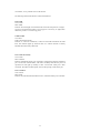
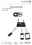
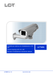
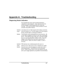
FHU-1604TXDS
FHU-2404TXDS
FHU-3204TXDS
16/24/32 Port Stackable 10/100Mbps
Dual-Speed Hub
User’s Manual
(Revision 1.0)
Edition 1.01 (Feb. 1998)
1
FCC Class A Appliance
This equipment generates and uses radio frequency energy. If it is not installed and
used properly in strict accordance with the manufacturer‘s instructions, it may
cause interference to radio and television reception. It has been type-tested and
found to comply the specifications in sub-part J of Part 15 of FCC Rules, which
are designed to provide reasonable protection against such interferencein a
residential installation. There is no guarantee that interference will not occur in a
particular installation. If this equipment does cause interference to radio or
television reception which can be determined by turning the equipment off and on,
the user is encouraged to try to correct the interference by one or more of the
following measures:
Re-orient the receiving antenna
l
Relocate the computing device with respect to the receiver
l
Move the computer away from the deceiver
l
Plug the computer into a different outlet so that computer
and receiver are on different electrical circuits.
If necessary the user should consult the dealer or an experienced radio or television
technician for additional suggestions.
The information in this manual is subject to change without notice. All
the brand names are registered trademarks of their respective companies.
2
Checklist
Carefully unpack the package and check its contents against the checklist giben
below.
Checklist of FHU-1603TXS/FHU-2403TXS/FHU-3203TXS 16/24/32 Port
100Mbps Stackable Ethernet Hub
l
l
l
l
l
l
16/24/32 Port 100Mbps Stackable Ethernet Hub
User‘s manual
Power cord
19” mount brackets
Stack cable
Plastic stand
Please inform your supplier immediately for any wrong, missing, or damaged part
if possible, retain the carton including the original packing materials, and use them
against to repack the product in case there is a need to return it to us for repair.
3
Contents
Introduction
Ethernet Standards and Operating Speeds
Fast Ethernet Hub Classes
100BASE-TX Fast Ethernet Cabling
100BASE-TX and 10BASE-T:Important Differences
100BASE-TX Fast Ethernet Summary
Features and Specification
Specification
Features
Installation
Hardware Description
Front Panel
Rear Panel
Hardware Installation
General Rules
Connecting End Nodes
Stacking two Hubs
Connecting the hub to Another Hub by Uplink port
Connecting the Hub to AC Power
4
Troubleshooting
Hub‘s RJ-45 Pin Assignments
Introduction
These hubs are technically known as 10/100BASE-TX Dual-Speed Ethernet hubs
and 100BASE-TX Fast Ethernet hubs. This Section describes what this means in
practical terms.
Ethernet Standards and Operation Speeds
Ethernet standards are defined by the Institute of Electrical and Electronics
Engineers ( IEEE ). The standard for traditional Ethernet using hubs and
twisted-pair cables is known as 10BASE-T. Traditional Ethernet works at a
signaling speed of 10 Mbps, that is, ten megabits ( slightly more than a characters)
per second.The BASE in 10BASE-T stands for “baseband,” a one-bit-at-a-time
signaling method; the T stands for twisted-pai cable.
Fast Ethernet was developed to meet the demand for increased “bandwidth,” in
other word, greater data-carrying capacity. A fast Ethernet hub works at 100Mbps,
ten times the speed of a 100BASE-T hub.
The IEEE had defined several Fast Ethernet Standards. The hub complies with the
100BASE-TX standard: 100 Mbps baseband signaling on twisted-pair cables, with
signals crossing from the Transmit lines to the Receive lines somewhere between
each pair of communction end noeds.
Fast Ethernet Hub Classes
This hub series are Class II Fast Ethernet hub. This means two things:
1.This hub series will work with Fast Ethernet interface cards of one type only,
5
and
2.This hub series can be connected to another hub for the purpose of expanding the
network.
Note: A Class I hub will work with more than one type of Fast Ethernet interface
card, but cannot be connected to another hub.
100BASE-TX Fast Ethernet Cabling
The twisted-pair cables used for traditional Ethernet and Fast Ethernet all look the
same on the outside. Such cables, however, come in different grades and with
different wire arrangement, and can have different kinds of sheathing.
The kinds of cables that can be used with a 100BASE-TX Class II Fast Ethernet
hub are
l
l
Category 5 unshielded twisted-pair cable, and ( Category 5 UTP)
Type 1 shielded twisted-pair cable (Type 1 STP )
100BASE-TX Fast Ethernet Summary
Be sure to remember the following rules about a 100BASE-TX Class II Fast
Ethernet hub:
1. All end nodes connected to the hub must have 100BASE-TX Fast Ethernet
interface cards.
2. Only Category 5 UTP or Type 1 STP cables may be used to connect and nodes
to the hub. The cables must be straight-wired.
3. To expand a network built around one Fast Ethernet hub, you can connect the
hub to one and only one other 100BASE-TX Class II hub.
6
Features and Specifications
Features
1. Comply with the IEEE802.3u 100Base-TX Class II standard.
2. The 100Mbps Stackable Ethernet Hub are
FHU-1603TXS: 16-port fast Ethernet hub
FHU-2403TXS: 24-port fast Ethernet hub
FHU-3203TXS: 32-port fast Ethernet hub
The fast and dual speed Rack-Mount products’ series can stack up each.
3. Four different modules provide multiple options to enhance the ability of
expansion of network.
MDU-0115B:
10Base-2 BNC switching module
MDU-0116TX: 10/100Base-TX 10/100Mbps NWay switching module
MDU-0117FXT: 100Mbps Fiber (ST) switching module
7
MDU-0117FXC: 100Mbps Fiber (SC) switching module
4. At rear panel, there are two stack connectors for stacking up to 3 units max.
5. At the front panel of 19” case, one push-bottom switch to setting the
corresponding port as “normal port” or “Up-link port”. The “reset” switch is for
reboot the hub.
6. 19” case size design for rack-mount series
7. LED indicators array for simple diagnostics and management
Specifications:
Standard:
IEEE802.3u 100BASE-TX
Network Media:
100BASE-TX – UTP/STP category 5 cable
10BASE-T – UTP/STP category 3 or 5 cable
Connector:
STP RJ-45 ports for 10/100Mbps
1 RJ-45 connector for Up-link port
Stacking ports
LED indicators:
System – power and collision LEDs
Individual port – link/activity and partition LEDs
Dimension:
200mm(W) x 430mm(L) x 44mm(H)
Temperature:
Operating -- 0? to 50?
Storage -- -20? to 70?
Humidity:
Operating – 10% to 90% RH
8
Storage – 5% to 90% RH
Input Power Requirement: 100-240 VAC, 50-60Hz
Registrations:
FCC Part 15 Class A, CE
Installation
Hardware Description
Fast Ethernet products provide only 100Mbps.
The fast and dual speed Rack-mount hubs can stack up each other, but in a stack
only one hub’s internal switching function is enabled and the others will be
disabled automatically.
For the network size expansion, provide four different function modules:
* MDU-0115B: one BNC port for connecting to 10Base-2 network
* MDU-0116TX: one full switching function 10/100Mbps TX ports
* MDU-0117FXT: one full switching function 100Mbps port for ST fiber
* MDU-0117FXC:
one full switching function 100Mbps port for SC fiber
All modules provide a port with the ability to extend the cable length between hubs
in 100 meters for TX and 2000 meters for FX and over the limitation of
9
100BASE-TX Class II standard. Normally, the distance between two Class II hubs
is 5 meters. This special ability allows user to use the bridging port as daisy-chain
port(just like as 10BASE-T) and to expand the network size more flexible and the
cabling system is similar to 10BASE-T.
Front panel
The following figure shows the front panel of 100Mbps Stackable Ethernet Hub
FHU-1603TXS Front Panel
FHU-2403TXS Front Panel
FHU-3203TXS Front Panel
l
All ports‘ Transmit and Receive lines are crossed within the hub. A
10/100BASE-TX port must be internally cross-wired to let you connect an
end node using straight-wired cabling.
For FHU-1603TXS/FHU-2403TXS/FHU-3203TXS Series
A special push-bottom switch is for setting the corresponding RJ-45 connector
into “Normal” or “Up-link” mode. For example, 16-port dual speed hub, the 12th
port can be act as normal port or “Up-ink” port by pushing the switch. The
“Up -link” port is used for connection another hub through an ordinary straightwired twisted-pair cable by running one end of straight cable to “Up -link” port and
the other end to another hub‘s station port.
On the front panel, there are several LED indicators for monitoring the device itself,
and the network status. At a quick glance of the front panel, the user would be able
to tell if the product is receiving power; if it is monitoring another hub or
10
concentrator; or if a problem exists on the network.
The following describes the function of each LED indicator
Power LED
Color: Green
Lable: PWR
Function: This LED light is located at the left side on the front panel. It will light
up (ON ) to show that the product is receiving power. Conversely, no light (OFF)
means the product is not receiving power.
Collision LED
Color: Red
Label: COL10 and COL100
Function: A “collision” in Ethernet, is when two end nodes transmit at the same
time. The indicator lights up whenever there is a collision between a directly
attached end node and any other node
Port’s Link and Activity
Color: Green
Label: Link/Act
Function: Each RJ45 station port on the hub is assigned one LED for monitoring
port “Good Link” and data traffic. The LED is normally OFF after the power on
operation, but will light up steadily to show “Good Link” when port is been
connected. The LED will flash rapidly to show data passing in and out the port.
Port’s Partition
Color: Yellow
Label: PAR
Function: For fast Ethernet Rack-Mount series, each RJ45 station port on the hub
11
is assigned one LED to indicate the partition status. The LED is normally in state
of “Off” after power on operation. If that port is partitioning, the LED will keep
“On”, otherwise, keeping “Off”
On the front panel also has several LEDs to indicate the status of expansion
module.
Expansion Port’s Activity
Color: Green
Label: ACT
Function: The LED will flash rapidly to show data passing in and out the port.
BNC Module Installed
Color: Yellow
Label: BNC
Function: The LED light up steadily means that 10Base-2 BNC module installed.
TX Module Installed
Color: Green
Label: TXM
Function: The LED light up steadily means that 10/100Base-TX module installed.
FX Module Installed
Color: Yellow
Label: FXM
Function: The LED light up steadily means that 100Base-FX fiber module
installed.
Rear Panel
On the rear panel there are AC power inlet, power switch, fans, and stack
connectors. The following describes the function of each connector and switch.
12
FHU-1603TXS/FHU-2403TXS/FHU-3203TXS Series
Power Connector
For FHU-1603TXS/FHU-2403TXS/FHU-3203TXS Series
AC Power Inlet
The power cord should be plug into this socket. The AC power inlet accepts AC
voltage equal to 100-240VAC, 50-60 Hz.
Stack Connectors
For FHU-1603TXS/FHU-2403TXS/FHU-3203TXS Series
There are two DB-25 connectors at rear panel with same pin definition and
function. These connectors are for stacking up several hubs to expanding the
station ports. By driving one end of cable to anyone connector of one hub and the
other end to another hub’s stack connector. No ID switch for setting, the ID
address will automatically assign when stack cable connected.
Expansion Slot
This slot is for four different modules. The status LED of module will display on
module itself and front panel.
Hardware Installation
After selecting an appropriate location, you are ready to connect it. This section
covers important rules -- fast Ethernet connections, and how to connect the hub to
end nodes, another hub, and power supply.
General Rules
13
Before making any connections to the hub, note the following rules:
l
All network connections to the hub must be made using Category 5 UTP or
Type 1 STP cables. Do not use similar-looking Category 2 or 3 cables or
“flat satin” telephone cords.
l
No more than 100 meters ( about 328 feet ) of cabling may be used between
the hub and an end node; no more than 5 meters (16.4 feet) may be used
between two sacks. Each stack is composed up to 2 hubs max. Under this
limitation, no more than 205 meters of cabling may be used between any two
end nodes.
l
To expand your network, you have three methods:
First -- you can connect the hub to another 100BASE-TX Class II Fast
Ethernet hub, but not to more than one, and not to any other kind of hub
through “Uplink” port. These two hubs can come from different suppliers.
Second -- you can connect the hub to another hub by stack connector. The
function of stack connector is defined by manufacture, therefore, different
vandor supplied hubs car not be connected togther.
Third -- Two stacks can connect together by using method one, i.e. choosing
one station port from the first stack and one “Uplink” port from another
stack, and linking these two ports within 5 meters (16.4 feet ) length.
Connecting End Nodes
LAN end nodes such as single-user computers, serveres, bridges, and routers must
be connected to the 100BASE-TX ports using straight-wired high-grade (Category
5 unshielded or Type 1 shielded) twisted-pair cabling.
l
We recommend starting with the higher-numbered ports when connecting
Ethernet LAN and the new hub does not have an “Uplink” port or switch,
14
you will have to use “Uplink” port on the hub for the connection.
l
We also recommend making sure the end node is turned off before plugging
the cable in for the first time. If the plug does not fit well and the nose‘s
LAN board is loose, forcible insertion can momentarily break an internal
contact and damage the end node.
Followings are step-by-step instructions for connecting and end node to the hub
using straight-wired twisted-pair cable.
1. Select a port on the hub
2. Plug one end of the cable into the node‘s RJ-45 jack.
3. Plug the cable‘s other end into the selected RJ-45 jack on the hub.
To test and end-node connection, connect the hub to power, then turn the hub and
the end node on. The link indicator for the port should shine steadily. If it does not,
check the cable and all connections.
Stacking two Hubs
For FHU-1603TXS/FHU-2403TXS/FHU-3203TXS Series
Two hubs can be connected by an attached stack cable – 25-pin D-sub cable.
1. Connect one end to stack port of hub.
2. Connect the other end to another stack port of another hub. These two hubs are
stacked.
Connecting the Hub to Another Hub by Uplink port
You can connect the hub to another 100BASSE-TX Class II Fast Ethernet hub
using a twisted-pair cable. Never, connect the hub to any other kind of hub, or to
more than one 100BASE-TX Class II hub.
15
Make the connection as follows:
1. Make sure “Up-link” port on the hub is free.
2. Plug one end of the cable into “Uplink” port on the hub.
3. Plug the cable‘s other end into the available port ( except “Up-link” port ) on the
second hub.
Connecting the Hub to DC Power
After making network connections as described in the preceding sections, you are
ready to plug the hub in and turn it on.
The hub can run on AC power with 100-240VAC, 50-60Hz, auto-sensing.
Before plugging the hub in, make sure the power cord ( 1 ) is long enough to reach
an AC wall outlet of an approved type, ( 2 ) has plugs that match both the hub‘s
power inlet and the type of wall outlet you will use, and ( 3 ) conforms to safety
regulations in your area.
Troubleshooting
Symptom: Link indicator remains off
Causes: Workstation‘s network adapter, cable or hub port is defective.
Solution: The most common cause is a defective network adapter or cable
connection. Check the corresponding cable connections, or the
workstations’ network adapter for possible defects. Verify that the
correct cable type is being used. ( Note that crossover cable is
only required if you cascade hubs via RJ45 station ports, i.e. an
uplink port is not used.) Replace the defective cable or adapter.
Some network adapters’ link indicator needs to be initialized by
software driver. Therefore, if no driver is pre-loaded ,the hub‘s link
indicator will remain off even the connection completed.
16
Hub‘s RJ-45 Pin Assignments
Pin
1
2
2
6
4,5,7,8
Station Ports 1-8
Input Receive Data +
Input Receive Data Output Transmit Data+
Output Transmit DataNot used
Uplink Port
Output Transmit Data+
Output Transmit DataInput Receive Data +
Input Receive Data Not used
Schematics for both straight and crossover twisted-pair cable are shown below.
( Note that crossover cable is only required if you cascade hubs via the RJ-45
station ports; i.e. the Uplink port is not used.)
Straight-Through
(Hub)
1 IDR+
2 IRD3 OTD+
6 OTD-
Crossover
(Adapter)
1 OTD+
2 OTD3 IRD+
6 IRD-
(Hub)
1 IRD+
2 IRD3 OTD+
6 OTD-
17
(Hub)
1 IRD+
2 IRD.
3 IRD6 IRD-
- 13 -
18