1
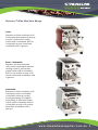
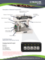
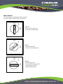
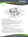
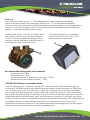
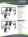
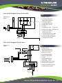
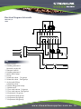
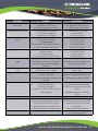
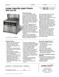
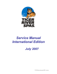
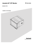
Eroica
Operating
Instructions
Streamline Supplies
9 Joseph Baldwin Place,
Shepparton Victoria 3630
Ph.: 03 5831 5555
Fax: 03 5821 3633
www.streamlinesupplies.com.au 1
Introduction
Please read this technical handbook carefully as it provides
important information on the correct installation, use and
maintenance. Keep this handbook in a safe place for further
consultation. The Manufacturer is not responsible for any damage
caused by incorrect or unreasonable use and maintenance. The
Manufacturer accepts no responsibility for damage to persons
or objects caused by incorrect installation. The instructions in this
handbook are in no way a substitute for the safety instructions and
technical data on the machine or the packaging concerning
installation and function. This handbook is an essential part of the
machine. For further information or additional handbooks, please
contact your distributor or the manufacturer. This handbook reflects
the current manufacturing requirements and is subject to change
according to future modifications. The Manufacturer is free to
modify this manual without updating previous editions except in
exceptional cases. This machine is to be operated according to
the instructions supplied in the handbook by a responsible adult
operator, installation and/or service technician.
www.streamlinesupplies.com.au 2
Instructions for use
This machine is designed for the sole purpose of producing coffee, hot water and steam
for hot drinks. All other uses are incorrect and, therefore, dangerous. This machine is
designed for professional use only. The machine components are made of non-toxic and
long lasting parts which are easily accessed for cleaning and maintenance. The end
user must be an adult, sufficiently trained to operate the appliance properly and it must
forbid the use of the appliance to children or non-responsible persons. To ensure efficient
and correct operation it is essential to follow the Manufacturer’s instructions concerning
the periodic maintenance carried out by authorized technicians in compliant with the
local standards and laws. The installation technician, the user and the person in charge of
maintenance are obliged to inform the manufacturer of any defects or damages which
could affect the safety of the original installation. The installation technician must check
the surrounding area to ensure safe and hygienic use are guaranteed. The machine
components’ Manufacturers are responsible for the parts supplied by them. The Customer
is responsible for the personal use of the equipment. Do not expose the machine to
environmental elements (sun, rain, etc.). When the machine is idle and not in use for an
extended period of time, it should be emptied completely and stored in an area with
temperature above freezing (0º C or 32º F). This prevents any possible damage to pipes
and boiler. All maintenance procedures must be carried out exclusively by authorized
technicians and all spare-parts must be genuine. Any modification or forcing performed
by persons not authorized by the Manufacturer will void all warranties covering the
appliance. The motor-pump set must be position far from hydraulic pipes, heat sources,
electrical appliances or it must be protected by a water-resistant aerated enclosure.
WARNING:
Before performing tests and maintenance
procedures DISCONNECT MACHINE FROM
MAINS.
Never pull the electrical supply cable.
Unplug the machine or turn off the main
switch before cleaning the machines
interior.
Never use detergents of any kind.
To reduce the risk of electrical shock,
avoid operating the machine with wet
hands or
feet and do not operate the machine
with bare fee.
The machine has to be installed with an
efficient ground system; the Manufacturer
recommends a wooden platform on
which the operator can stand.
Never touch coffee groups, spouts, steam
and hot water pipes. They are HOT and
could cause burns.
Never operate the machine without
water.
The machine must be operated with
clean water. This must be filtered water
with filters replaced every 6 months.
Use water softeners if the water has a
high mineral content. Mineral deposits
may obstruct the machine’s water
circuit which may cause damage to the
machine and possibly personal injury.
The machine must operate only with
drinking water.
The machine has to be switched
off whenever unattended from the
operator.
Tea and coffee cups must be carefully
drained before placing them over the
cup-tray.
www.streamlinesupplies.com.au 3
Espresso Coffee Machine Range
Lever
Espresso coffee machine with
lever operated manual dosing
control. Automatic water
boiler refill is standard. Built-in
volumetric pump. Machine
available with 2 groups
Semi – Automatic
Espresso coffee machine
with switch operated manual
dosing control. Automatic
water boiler refill is standard.
Built-in volumetric pump with
motor. Machine available with
2 groups.
Automatic
Espresso coffee machine with
microprocessor-controlled
volumetric dosing control
& programming via digital
keyboard. Automatic boiler
water refill is standard. Built-in
volumetric pump with motor.
Machine available with 2
groups.
www.streamlinesupplies.com.au 4
Description of External Components.
Keyboard for Coffee
Delivery Service
Hot Water
Control Knob
Stream Control knob
Boiler Pressure Gauge
Mains Pilot Lamp
Hot Water Wand
Main Switch
Boiler Water
Level Indicator
Steam Wand
Push Button Panel
(keyboard for Coffe Delivery Service)
Ranging from left to right
Ristretto
Espresso
Two Ristrettos
Two Espressos
Manual Delivery
The programming operation between a key and the
other has to be completed within 30 seconds, otherwise
the memory will be lost. For partial keyboard dosesetting push star key again after the last selected dose
key has been programmed.
www.streamlinesupplies.com.au 5
Function of the machine
The main components of the espresso coffee
machine are the following:
BOILER
Contains hot water and steam.
HOT-WATER TAP
This delivers hot water.
COFFEE DELIVERY GROUP AND
HEAT EXCHANGERS
This is the component where the filter holder
is inserted. The hot water enters the delivery
group, where the processes of pre-infusion,
infusion and delivery of the coffee take place.
The machine comes with one heat exchanger
for each delivery group. The heat exchanger
is fitted in the boiler and it’s purpose is to heat
up the fresh water coming from the mains to
the correct temperature.
CONTROL & MONITORING DEVICES
Pressure gauge
Indicates the boiler pressure and the
working pressure of the pump.
Pressure switch
This is used to keep the boiler water
temperature constant by controlling the
heating elements, based on the boiler
pressure.
Automatic Boiler
Water Level Control: Electronic circuitry
used to the boiler water
level constant.
HEATING SOURCE
An electric element warms the water in the
boiler.
ELECTRIC PUMP
This component is to increase the water
pressure of the mains to the correct water
pressure needed for espresso coffee
preparation which is 9 bars.
STEAM WAND
This wand delivers hot steam for milk
frothing and steaming of drinks in jugs (tea,
chocolates, etc.)
HYDRAULIC CIRCUIT
The hydraulic diagram shows that the
water used for the preparation of coffee
comes directly from the mains and is
heated in the heat exchangers inside
the boiler.
Electric Diagram
The machine is connected to the electric mains by a supply cable.
As shown on the electric diagram there are two circuits:
- A feeding circuit for electric components (solenoid valves, pump
motor, electronic control panel.
- A feeding circuit for the heating element.
ATTENTION: In all cases, this appliance must be connected to a 3 pin
power point or a hard wired (direct wired) power source. The use of
extension leads or loose type connectors is strictly forbidden
and unlawful.
www.streamlinesupplies.com.au 6
Main Switch
The machine is equipped with a main
power supply switch with 3 positions.
0
0
0
1
2
Pos. 0
No power supply to
internal components.
2
Pos. 1
Power supply to
function components.
1
1
2
Pos. 2
Power supply to
functional components
and electric boiler
heating elements.
www.streamlinesupplies.com.au 7
Installation Warnings
Please read carefully
The Manufacturer has tried to foresee all possible safety requirements to ensure the safety
of users. Anyhow, different conditions of installation or of equipment moving can cause
situations which cannot be controlled or foreseen. Therefore, it’s absolutely necessary to
evaluate all remaining risks and to care about the following suggestions:
- This machine is safe only if appropriately connected to an efficient grounding system
complying with the safety standards in force the Country where the machine will be
installed. The Manufacturer rejects any responsibility for accidents due to the missed application of the above standards, since a wrong installation may result in injuries to persons, as well as other problems that may affect other areas.
- Do not leave packing items such as plastic bags, Styrofoam, nails etc. around because children or other persons could get injured.
- Any defect or discrepancy has to be notified immediately to the persons authorized for installation and maintenance of the machine.
- Machine installation has to be performed exclusively by authorized and qualified technicians.
- Authorized service: if the service is not complying with the instruction of the Manufacturer, or is components other than those recommended by the Manufacturer will be used for installation or maintenance of the appliance, the conformity declaration of the product will be voided, and so the Manufacturer’s responsibility.
- Possible replacement of the supply cable, if damaged, must be performed immediately and exclusively by service staff qualified or authorized by the Manufacturer, in order to prevent any danger to persons.
- Before the connection of the appliance to the fixed installation, verify if a conformity certificate has been issued to confirm the suitability of the fixed installation for this use; if not, inform the end user and leave the appliance disconnected.
- Check the integrity of all components and do not install defective or damaged parts. Ask for substitution.
- Check and verify that the outlet power supply voltage is the same as shown on the rating-plate of the appliance.
- The customer has to protect the power outlet used to supply the appliance by means of a safety switch system, complying with the standards and laws in force.
- The installation of a water softener is highly recommended.
- Machine should not be installed with supplying water having hardness degree higher than 8 French degrees. It is imperative that a suitable water filter is installed in line prior to the machine and the cartridge changed every 6 months.
- The motor-pump set must be positioned far from hydraulic pipes, heat sources, electrical appliances or it must by protected by a water resistant aerated enclosure.
- When installing the appliance, a multi-pole main switch having contacts with opening gap equivalent or higher than 3 mm should be connected, as requested by the
safety standards.
- Any unreliable cable connection is forbidden.
- The appliance must be placed over a flat and stable surface, leaving a minimum
clearance of 30 mm from walls.
www.streamlinesupplies.com.au 8
Installation
Water
drain vessel
Electric
supply cable
Main switch
Water feed
from the mains
Water inlet
connection
Water
inlet valve
Water
drain hose
Water hose
to drain
Pipe from water softener
to water inlet
Mains switch
(not provided)
Electrical
connection
to the mains
Water filter
POSITIONING AND CONNECTIONS
Before installation the Manufacturer strongly recommend to control the water
supply system and the electrical connections.
Check the mains pressure which should not exceed 6 bar, otherwise it is
recommended the installation of a water pressure reducer.
The machine must be installed with a mains electrical switch with adequate fuses.
Attention: the machine must be connected to an efficient earthling
system (yellow-green-cable).
Check the efficiency of the main drain hose (part 8). Then proceed with
the connection of the water drain hose to the machine (part 7).
Hydraulic connections:
- water inlet 3/8” BSP water (male fitting)
- water drain hose internal Ø 14 mm.
The machine must be installed on a stable surface find a good position for the
water softener (part 12). Connect the valve (part 9) to pipe (part 11). Connect
the pipe to the water inlet connector (part 5). Connect the pipe (part 7) to the
discharge recipient (part 6) and then on the general discharge (part 8). Put a
recipient under the water softener discharge pipe and let out the water for a few
minutes to clean the resin. Effect the electric connection between the feeding
(part 3) and the switch (part 2).
www.streamlinesupplies.com.au 9
Start up
Turn the main switch to pos. “1”. The filling process will proceed automatically.
When the boiler is filled, turn the main switch to pos. “2” to activate the heating
element’s electrical feed. Wait until boiler pressure reaches maximum working pressure
(approx. 1 bar).Open steam valve for a few seconds. Be sure Boiler pressure reaches
approx. 1 bar after releasing steam valve.
Prepare one dose of coffee. As coffee flows,
check the correct pump pressure (approx.
9 bar) on the pump pressure gauge. Pump
pressure can be adjusted using the screw A
positioned on the pump’s by-pass.
The boiler pressure is controlled by
a pressure switch. Turn screw A for
boiler pressure adjustment.
A
A
Recommended working data of the machine
Pump pressure: 9 Bar
Boiler pressure: 1 Bar
Opening pressure of boiler Security valve: 1.5 Bar
Expansion valve opening Pressure: 11 Bar
COFFEE-DOSE Setting on Automatic Model.
Hold the star key (pos.1) pressed until all LED’s are switched on the keyboard (group
on the left). Put filter holder with perfectly ground dosed coffee in the group. Place the
cup for which you want to set the dose under the coffee group. Push the key related
to the selected dose and push it again when the correct quantity of coffee is reached.
Repeat this for dose setting of each key. Once the dose for one brewing group is set, the
same dose will be simultaneously set in the other group; however, for a more accurate
dosing, we recommend to program each group keyboard individually. The programming
operation between a key and the other has to be completed within 30 seconds,
otherwise the memory will be lost. For partial keyboard dose-setting push star key again
after the last selected dose key has been programmed.
w w w . s t r e a m l i n e s u p p l i e s . c o m . a u 10
Maintenance
Manufacturer – recommended cleaning procedures to be performed at the
end of each working day.
- Clean showers, group gaskets, group flange with a brush.
- Wash filters and filter holder in warm water adding a special detergent product (for use with coffee machines).
- Put the filter holder with the blind filter in the coffee delivery group and press the button for semi-automatic coffee delivery. Switch it off after 15 seconds. Remove the filter holder and take the blind filter out.
- Clean the cup tray and grid without removing the tray from the machine.
- Clean the steam wands and spout accurately with a non abrasive damp
cloth immediately after each single to prevent clogging of the steam holes and taste persistence of previously steamed drinks. Do it without touching the wands directly. Caution: HOT Surface.
Manufacturer – recommended weekly cleaning operations.
- The group and shower plate are cleaning by putting one teaspoon of special espresso machine detergent in the blind filter and then inserting it into the group.
- Press the button for semi-automatic working and wait about 30 seconds. Push this button again to stop. Repeat this operation for 3 to 4 times.
- Remove blind filter and replace it with the regular filter, continue rinsing. Finally, prepare one coffee to remove residual detergent taste.
- Turn the machine off prior to proceeding to the following operations:
- Clean the drip tray and grid
- Clean the plastic recipient located in the part under the drip tray. Use a spoon for this purpose.
- Clean the body-work with a non abrasive damp cloth. Never use aggressive products or alcohol.
- Periodic regeneration of water softener.
Streamline Supplies
Recommends the use of:
w w w . s t r e a m l i n e s u p p l i e s . c o m . a u 11
Water Circuit Semi-automatic 2 group.
Key
11
B
A
13
9
8
12
4 5
10
7
6
3
1
2
Water circuit, Automatic 2 Group
Key
11
B
A
13
14
9
14
8
12
4 5
6
3
2
10
7
1
A. Boiler
B. Heat exchange
1. Water circuit feeding pipe
2. Pump
3. Boiler water Filling
Solenoid valve
4. Non-return Valve
5. Exapansion valve
6. Water Discharge Vessel
7. Coffee delivery group
8. Pump/boiler
9. Steam valve
10. Water valve
11. Secruity valve
12. Delivery group
solenoid-valve
13. Pressure switch
A. Boiler
B. Heat exchange
1. Water circuit feeding pipe
2. Pump
3. Boiler water filling
Solenoid valve
4. Non-return valve
5. Expansion valve
6. Water discharge vessel
7. Coffee delivery group
8. Pump/boiler pressure guage
9. Steam valve
10. Water valve
11. Security valve
12. Delivery group
solenoid-valve.
13. Pressure switch
14. Volumetric counter
(flow-rate sensor.)
w w w . s t r e a m l i n e s u p p l i e s . c o m . a u 12
Electrical Diagram Semi-Automatic
EROICA S/2
230V
4
1. Main switch
2. Heating element
thermal protector
3. Pressure switch
4. Heating element
5. Mains pilot lamp
6. Pump
7. Solenoid valve - 1st group
8. Solenoid valve - 2nd group
9. Automatic filling
solenoid valve
10. Boiler filling pilot lamp
11. Keyboard 1st group
12. Keyboard 2nd group
13. Boiler lever sesor
8
7
9
Key
3
2
5
10
6
1
13
12 11
Electrical Diagram Hand Lever
EROICA L/2
230V
8
2
3
4
7
6
1
5
Key
1. Main switch
2. Heating element
thermal protector
3. Pressure switch
4. Heating element
5. Mains pilot lamp
6. Pump
7. Automatic filling
solenoid - valve
8. Boiler filling pilot lamp
9. Keyboard 1st group
10. Keyboard 2nd group
11. Boiler level sensor
9
10
11
w w w . s t r e a m l i n e s u p p l i e s . c o m . a u 13
Electrical Diagram Automatic
EROICA S/2
230V
12
11
13
1
5
6
7
8
9
10
Key
1. Main switch
2. Heating element
thermal protector
3. Pressure switch
4. Heating element
5. Mains pilot lamp
6. Pump
7. Solenoid valve - 1st group
8. Solenoid valve - 2nd group
9. Automatic filling
solenoid valve
10. Boiler filling pilot lamp
11. Boiler level
12. Flow rate sensor 1st group
13. Flow rate sensor 2nd group
14. Keyboard 1st group
15. Keyboard 2nd group
16. Keyboard 3rd group
17. Keyboard 4th group
2
3
4
w w w . s t r e a m l i n e s u p p l i e s . c o m . a u 14
TROUBLE
CAUSE
SOLUTION
the appliance dosen’t
switch ON
1. main switch id off
2. appliance switch if off
3. wrong connection to mains
1. set main switch in on
2. set appliance switch in pos. 1
3. contact service for check
missing hot water in boiler
1. water source tap closed
2. pump filter clogged
3. motor-pump set failure
1. open water source tap
2. replace filter
3. contact service
missing coffee delivery from
group
1. water source tap closed
2. motor-pump set failure
3. clogged giggler
4. electronic control unit fuse melt
5. group solenoid-valve failure
1. Open water source tap
2. Contact service
3. Contact service
4. Contact service
5. Contact service
missing steam from lances
1. Too much water in boiler 2. Heating
element failure
3. Sprayer clogged
4. Heating element protector trip
1. See SPECIFIC TROUBLE
2. Contact service
3. Clean sprayer
4. Reset protector
water level in boiler is too
high
1. The pump motor always run 2. Heatexchange is perforated 3. Solenoidvalve for automatic water filling is
blocked
1. Replace motor
2. Replace heat exchanger 3. Replace solenoid-valve
water leakages on table
top
1. Exhaust basin is dirty 2. Exhaust pipe
is disconnected or clogged
1. Clean exhaust basin 2. Replace
exhaust pipe
Coffee dregs are wet
1. Coffee grinding is too fine
2. Group is still cold
3. Group solenoid-valve doesn’t work
properly
1. Adjust grinding degree
2. Wait for appliance to get warm
3. Clean group exhaust system
Coffee delivery is too slow
1. Coffee grinding is too fine
2. Filter holder is dirty
3. Group is clogged
4. Injector or solenoid-valve are partially clogged
1. Adjust grinding degree
2. Replace filter and clean filter
holder more frequently 3. Contact
service
4. Replace injector or solenoidvalve
Coffee delivery is too fast
1. Coffee grinding is too rough
1. Adjust grinding degree
Delivered coffee is cold
1. Heat-exchangers or heating element coated with limestone 2. Pressure-switch contacts are oxidised
3. Defective electrical connections
4. Heating element is partially burned
1. Contact service for overhauling
2. Clean pressure-switch contacts
3. Contact service to check the
connections
4. Replace heating element
Delivered coffee is too hot
1. Wrong pressure-switch calibration
1. Adjust pressure-switch by acting
on the relevant screw
w w w . s t r e a m l i n e s u p p l i e s . c o m . a u 15
Warranty Conditions
The warranty period is 12 months from the installation effected by an authorized
la SCALA technician and covers the faulty parts only. Not included are transport costs
and labour cost. Cannot be considered under our responsibility non installation of in line
water filter, periodic change of water filter damage in transit, damage due to incorrect
installation or maintenance, periodic regeneration of water softener not effected,
problems caused from the electric and hydraulic supplies of the client, installation by
non authorized persons, non genuine parts, seals, filters, gutters etc. Not included in
the warranty conditions are incorrect use of the machine and non-observance of the
maintenance and technical handbook. For no reason can the buyer delay or suspend
the payment agreed, this forfeits all rights and the guarantee.
Streamline Supplies
9 Joseph Baldwin Place,
Shepparton Victoria 3630
Ph: 03 5831 5555
Fax: 03 5821 3633
w w w . s t r e a m l i n e s u p p l i e s . c o m . a u 16