1
Solution-16/
Solution-16 Safecom
Installation Manual
ISSUE 2.22
MA880I
Solution-16/
Solution-16
This page has been included for you to cut out and insert into the spine
of the folder
Safecom
Installation
Manual
ISSUE 2.22
(61-2) 9672 1777
Solution-16/Solution-16 Safecom
Installation Manual
Copyright 2001 by Electronics Design & Manufacturing Pty Limited,
SYDNEY, AUSTRALIA
Document Part Number MA880I
Document Issue 2.22
Printed 1/4/2002
This documentation is provided to suit Solution-16 Control Panel (CC880/LP880 + SC8016)
Firmware Revision 1.10 - 2.06
Hardware Revision E - M
This installation manual includes programming locations to suit both Solution-16 (CC880/LP880) and the Solution16 Safecom (SC8016) control panel. Locations that are only relevant when using the SC8016 are prefixed with the
word Safecom.
Copyright Notice
All rights reserved. No part of this publication may be reproduced, transmitted or stored in a retrieval system in any form or
by any means, electronic, mechanical, photocopying, recording, or otherwise, without the prior written permission of
Electronics Design and Manufacturing Pty Limited.
Trademarks
Throughout this document trademark names may have been used. Rather than put a trademark symbol in every occurrence
of a trademark name, we state that we are using the names only in an editorial fashion and to the benefit of the trademark
owner with no intention of infringement of the trademark.
Notice of Liability
While every precaution has been taken in the preparation of this document, neither Electronics Design & Manufacturing Pty
Limited nor any of its official representatives shall have any liability to any person or entity with respect to any liability,
loss or damage caused or alleged to be caused directly or indirectly by the information contained in this book.
Electronics Design & Manufacturing Pty Limited reserves the right to make changes to features and specifications at any
time without prior notification in the interest of ongoing product development and improvement.
Table Of Contents
INTRODUCTION................................................................................................................................ 13
INTRODUCTION ..............................................................................................................................................................14
QUICK START ..................................................................................................................................................................15
TELEPERMIT NOTE ........................................................................................................................................................16
PROGRAMMING................................................................................................................................ 17
PROGRAMMING ..............................................................................................................................................................18
PROGRAMMING WITH THE REMOTE CODEPAD .....................................................................................................19
PROGRAMMING WITH THE HAND HELD PROGRAMMER .....................................................................................20
PROGRAMMING USING THE PROGRAMMING KEY ................................................................................................21
PROGRAMMING VIA THE DTMF COMMAND MODULE..........................................................................................22
How To Establish A Communication Link With The Control Panel ...........................................................................22
Programming The Control Panel Once A Communication Link Has Been Established ..............................................22
PROGRAMMING OPTION BITS .....................................................................................................................................22
INSTALLERS PROGRAMMING COMMANDS .............................................................................................................23
Command 958 - Enable/Disable Zone Status Mode ....................................................................................................23
Command 959 - Test Programming Key......................................................................................................................24
Command 960 - Exit Installer's Programming Mode...................................................................................................24
Command 961 - Reset Control Panel Back To Factory Default Settings.....................................................................24
Command 962 - Copy Control Panel Memory To Programming Key.........................................................................25
Command 963 - Copy From Programming Key To Control Panel ..............................................................................25
Command 964 - Erase Programming Key....................................................................................................................26
Command 965 - Set Up Domestic Dialling Format .....................................................................................................27
Command 966 - Enable/Disable Automatic Stepping Of Locations ............................................................................28
Command 999 - Display Software Version Number....................................................................................................28
Disable Factory Default...................................................................................................................................................29
DEFAULTING THE CONTROL PANEL .........................................................................................................................29
SYSTEM INDICATORS AND OPERATIONS................................................................................ 31
SYSTEM INDICATORS AND OPERATIONS.................................................................................................................32
The Codepad................................................................................................................................................................32
Zone Indicators ............................................................................................................................................................32
AWAY Indicator..........................................................................................................................................................32
STAY Indicator ...........................................................................................................................................................32
MAINS Indicator .........................................................................................................................................................33
FAULT Indicator .........................................................................................................................................................33
Audible Indicators........................................................................................................................................................33
LCD CODEPAD INDICATORS ........................................................................................................................................34
SYSTEM OPERATIONS ...................................................................................................................................................35
Arming The System In AWAY Mode.............................................................................................................................35
Forced Arming .............................................................................................................................................................35
Disarming The System From AWAY Mode ...................................................................................................................35
Arming The System In STAY Mode 1............................................................................................................................36
Forced Arming .............................................................................................................................................................36
Disarming The System From STAY Mode 1 ..................................................................................................................37
Arming The System In STAY Mode 2............................................................................................................................38
Forced Arming .............................................................................................................................................................38
Disarming The System From STAY Mode 2 ..................................................................................................................39
Codepad Duress Alarm ...................................................................................................................................................40
Codepad Panic Alarm - Software Version 1.10 - 1.36 ....................................................................................................40
Codepad Panic Alarm - Software Version 1.37 Onwards ...............................................................................................40
Codepad Fire Alarm - Software Version 1.37 Onwards..................................................................................................40
Codepad Medical Alarm - Software Version 1.37 ..........................................................................................................40
Isolating Zones ................................................................................................................................................................41
Standard Isolating ........................................................................................................................................................41
Code To Isolate............................................................................................................................................................41
Fault Analysis Mode .......................................................................................................................................................42
Fault Descriptions ...........................................................................................................................................................42
1
Low Battery.........................................................................................................................................................42
2
Date and Time.....................................................................................................................................................42
3
Sensor Watch ......................................................................................................................................................42
4
Horn Speaker Monitor ........................................................................................................................................43
5
Telephone Line Fault ..........................................................................................................................................43
6
E2 Fault...............................................................................................................................................................43
7
Zone 16 In Alarm - Partitioned Systems Only ....................................................................................................43
8
Communication Failure.......................................................................................................................................43
AC Mains Failure ........................................................................................................................................................43
SYSTEM FUNCTIONS........................................................................................................................45
SYSTEM FUNCTIONS .....................................................................................................................................................46
Installer Code Functions .................................................................................................................................................46
2
Set The Number Of Days Until The First Test Report........................................................................................46
3
Event Memory Recall Mode ...............................................................................................................................47
4
Walk Test Mode..................................................................................................................................................48
5
Satellite Siren Service Mode...............................................................................................................................48
7
Telephone Monitor Mode On and Off ................................................................................................................49
Master Code Functions ...................................................................................................................................................50
0
Arming and Disarming All Areas At The Same Time - Partitioned Systems Only .............................................50
1
Changing and Deleting User Codes ....................................................................................................................51
Auxiliary Codes...........................................................................................................................................................52
2
Programming Domestic Phone Numbers ............................................................................................................54
3
Event Memory Recall Mode ...............................................................................................................................55
4
Walk Test Mode..................................................................................................................................................56
5
Turning Outputs On and Off ...............................................................................................................................57
6
Setting The Date and Time .................................................................................................................................58
7
Turning Day Alarm On and Off (Software Version 1.10 Only) ..........................................................................58
8
Setting STAY Mode 2 Zones ..............................................................................................................................59
User Code Functions - Partitioned Systems Only ...........................................................................................................60
0
Arming and Disarming All Areas At The Same Time - Partitioned Systems Only .............................................60
Hold Down Functions .....................................................................................................................................................61
# Arm The System In AWAY Mode......................................................................................................................61
* Arm The System In STAY Mode 1.....................................................................................................................61
0 Arm The System In STAY Mode 2.....................................................................................................................61
1 Horn Speaker Test...............................................................................................................................................61
2 Bell Test..............................................................................................................................................................62
3 Strobe Test ..........................................................................................................................................................62
4 Turning Day Alarm On and Off (New - Software Version 1.20 Onwards) .........................................................62
5 Fault Analysis Mode ...........................................................................................................................................63
6 Initiate A Modem Call ........................................................................................................................................63
7 Reset Latching Outputs .......................................................................................................................................63
8 Codepad ID and Buzzer Tone Change................................................................................................................64
9 Initiate A Test Report..........................................................................................................................................64
REMOTE OPERATIONS ...................................................................................................................65
REMOTE OPERATIONS ..................................................................................................................................................66
Remote Arming Via The Telephone ...............................................................................................................................66
How To Remotely Arm Your System Via The Telephone ..........................................................................................66
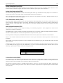
Operating The Control Panel Using The DTMF Command Module ..............................................................................67
Operation - Software From Version 1.10 ....................................................................................................................67
Operation - Software From Version 1.20 ....................................................................................................................67
Upload/Download Via Alarm Link Software..................................................................................................................69
Direct Connect.............................................................................................................................................................69
Remote Connect ..........................................................................................................................................................70
REPORTING FORMATS....................................................................................................................71
REPORTING FORMATS ..................................................................................................................................................72
Contact ID Format ..........................................................................................................................................................72
Event Codes ....................................................................................................................................................................73
Point ID Codes................................................................................................................................................................74
General Reporting Formats.............................................................................................................................................75
Securitel ..........................................................................................................................................................................77
How To Program and Set Up Securitel........................................................................................................................77
Securitel and Partitioning ................................................................................................................................................77
Domestic Reporting.........................................................................................................................................................78
Programming Domestic Reporting...............................................................................................................................78
Domestic Dialling Operation...........................................................................................................................................79
Acknowledge Domestic Dialling .................................................................................................................................79
Synthesised Voice Reporting ..........................................................................................................................................80
How To Set Up The Control Panel For Synthesised Voice Format.............................................................................80
How To Disable Synthesised Voice Dialling Using The Master Code........................................................................81
Synthesised Voice Dialling Operation.............................................................................................................................81
How To Acknowledge Synthesised Voice Dialling Without DTMF Command Module Fitted ..................................81
How To Acknowledge Synthesised Voice Dialling With DTMF Command Module Fitted .......................................81
Operation Of The Voice Module.....................................................................................................................................82
Recording The Voice Message ....................................................................................................................................82
Replay The Voice Message..........................................................................................................................................82
Connection Of The Voice Module...............................................................................................................................83
Basic Pager Format Reporting ........................................................................................................................................84
PET Alpha Pager Reporting............................................................................................................................................85
Programming and Hardware Requirements .................................................................................................................85
Telecom Access Telephone Numbers ..........................................................................................................................85
PET Alpha Pager Messages .........................................................................................................................................86
PET Alpha Pager Password.............................................................................................................................................87
Converting ASCII Characters To Hexadecimal ...........................................................................................................88
PET Alpha Pager ID Number..........................................................................................................................................88
Logging System Events Via Serial Printer ......................................................................................................................89
Printer Output Baud Rate ................................................................................................................................................89
BASE STATION INFORMATION.................................................................................................... 91
BASE STATION INFORMATION....................................................................................................................................92
How To Program A Phone Number.............................................................................................................................92
Primary Telephone Number ............................................................................................................................................92
Secondary Telephone Number ........................................................................................................................................93
Callback Telephone Number...........................................................................................................................................93
Dialling Format ...............................................................................................................................................................93
Handshake Tone..............................................................................................................................................................94
Transmission Format.......................................................................................................................................................94
Transmission Speed.........................................................................................................................................................95
Subscriber ID Number ....................................................................................................................................................96
Ring Count ......................................................................................................................................................................96
Answering Machine Bypass.........................................................................................................................................96
ACCESS CODES ................................................................................................................................. 97
ACCESS CODES................................................................................................................................................................98
Installer Code ..................................................................................................................................................................98
User Codes ......................................................................................................................................................................98
User Code Priority .......................................................................................................................................................99
Auxiliary Codes.............................................................................................................................................................101
Auxiliary Code 1 ...........................................................................................................................................................101
Auxiliary Code 2 ...........................................................................................................................................................101
Code Retries ..................................................................................................................................................................101
ZONE PROGRAMMING ................................................................................................................. 103
ZONE PROGRAMMING.................................................................................................................................................104
Zone Operating Information ......................................................................................................................................104
Zone Reporting Information ......................................................................................................................................104
Zone Defaults ................................................................................................................................................................104
Zone Types....................................................................................................................................................................105
0
Instant Zone.......................................................................................................................................................105
1
Handover Zone ..................................................................................................................................................105
2
Delay-1 Zone .....................................................................................................................................................105
3
Delay-2 Zone .....................................................................................................................................................105
4
Delay-3 Zone .....................................................................................................................................................105
5
Delay-4 Zone .....................................................................................................................................................105
6
Instant Zone + Isolated In STAY Mode 1 .........................................................................................................105
7
Handover Zone + Isolated In STAY Mode 1 ....................................................................................................105
8
Delay-1 Zone + Isolated In STAY Mode 1.......................................................................................................105
9
Delay-2 Zone + Isolated In STAY Mode 1.......................................................................................................106
10
Delay-3 Zone + Isolated In STAY Mode 1...................................................................................................106
11
Delay-4 Zone + Isolated In STAY Mode 1...................................................................................................106
12
24 Hour Burglary Zone .................................................................................................................................106
13
24 Hour Fire Zone.........................................................................................................................................106
14
Chime Zone (Follow Me)..............................................................................................................................106
15
Zone Not Used ..............................................................................................................................................106
Zone Options.................................................................................................................................................................107
1&2 Lockout Siren & Lockout Dialler..................................................................................................................107
4
Silent Alarm ......................................................................................................................................................107
8
Sensor Watch ....................................................................................................................................................108
Zone Pulse Count..........................................................................................................................................................108
Zone Pulse Count Handover .........................................................................................................................................109
Zone Pulse Count Time.................................................................................................................................................109
Day Alarm.....................................................................................................................................................................110
Day Alarm Resetting .................................................................................................................................................110
Day Alarm Latching ..................................................................................................................................................110
Day Alarm Operation - (Software Version 1.10) ..........................................................................................................111
Day Alarm Operation - (Software Version 1.20 Onwards) ...........................................................................................111
Day Alarm In Partitioning.............................................................................................................................................111
EOL Resistor Value ......................................................................................................................................................112
SYSTEM STATUS INFORMATION...............................................................................................113
SYSTEM STATUS INFORMATION..............................................................................................................................114
Zone Bypass Reports (1-8) ...........................................................................................................................................114
Zone Bypass Reports(9-16) ..........................................................................................................................................114
Zone Trouble Report (1-8)............................................................................................................................................115
Zone Trouble Report (9-16)..........................................................................................................................................115
Codepad Duress ............................................................................................................................................................116
Codepad Panic ..............................................................................................................................................................117
Access Denied...............................................................................................................................................................118
AC Fail..........................................................................................................................................................................118
Low Battery ..................................................................................................................................................................119
Program Altered Code ..................................................................................................................................................119
Sensor Watch ................................................................................................................................................................120
Open/Close Reports For Area 1 ....................................................................................................................................120
Safecom RF Fail ...........................................................................................................................................................121
Safecom Telco Fail .......................................................................................................................................................121
Safecom RF Jamming ...................................................................................................................................................121
Test Reports ..................................................................................................................................................................122
Test Report Options...................................................................................................................................................122
PROGRAMMABLE OUTPUTS .......................................................................................................123
PROGRAMMABLE OUTPUTS......................................................................................................................................124
Output Configurations...................................................................................................................................................125
Redirecting Outputs To The Codepad Buzzer ..............................................................................................................126
Safecom Remote Operation Of Outputs........................................................................................................................126
Example ........................................................................................................................................................................126
OUTPUT EVENT TYPES ...............................................................................................................................................127
Output Polarity - (Software Version 1.20 - 1.40)..........................................................................................................134
0
Output Not Used ...............................................................................................................................................134
1
Normally Open, Going Low..............................................................................................................................134
2
Normally Open, Pulsing Low............................................................................................................................134
3
Normally Open, One Shot Low.........................................................................................................................134
4
Normally Open, One Shot Low With Retrigger ................................................................................................134
5
Normally Open, One Shot Low With Reset ......................................................................................................134
6
Normally Open, One Shot Low With Alarm.....................................................................................................134
7
Normally Open, Latching Low.........................................................................................................................134
8
Normally Low, Going Open..............................................................................................................................135
9
Normally Low, Pulsing Open............................................................................................................................135
10
Normally Low, One Shot Open.....................................................................................................................135
11
Normally Low, One Shot Open With Retrigger ............................................................................................135
12
Normally Low, One Shot Open With Reset ..................................................................................................135
13
Normally Low, One Shot Open With Alarm .................................................................................................135
14
Normally Low, Latching Open......................................................................................................................135
Output Polarity - (Software Version 1.10 Only)............................................................................................................135
Timing Of Outputs ........................................................................................................................................................136
Pulsing Polarities...........................................................................................................................................................136
One Shot Polarities........................................................................................................................................................137
SYSTEM EVENT TIMERS.............................................................................................................. 139
SYSTEM EVENT TIMERS .............................................................................................................................................140
How To Program Entry/Exit Times...............................................................................................................................140
Entry Time .................................................................................................................................................................140
Entry Time 1 .................................................................................................................................................................140
Entry Time 2 .................................................................................................................................................................140
Entry Time 3 .................................................................................................................................................................140
Entry Time 4 .................................................................................................................................................................140
Exit Time.......................................................................................................................................................................141
Exit Time For AWAY Mode.........................................................................................................................................141
Exit Time For STAY Mode 1 .......................................................................................................................................141
Exit Time For STAY Mode 2 .......................................................................................................................................141
Entry Guard Time For STAY Mode .............................................................................................................................141
Codepad Lockout Time.................................................................................................................................................142
Sensor Watch Time .......................................................................................................................................................142
Safecom RF Jamming Delay .........................................................................................................................................142
Safecom RF Supervision Time......................................................................................................................................142
System Date...................................................................................................................................................................143
Setting The Date and Time ........................................................................................................................................143
Auto Arming Time ........................................................................................................................................................144
Auto Arming Pre-Alert Time ........................................................................................................................................144
Timed Output Pre-Alert Time .......................................................................................................................................145
Auto Operation Of The Timed Output ..........................................................................................................................145
Siren Run Time .............................................................................................................................................................145
Siren Sound Rate...........................................................................................................................................................146
Swinger Shutdown Count ..............................................................................................................................................146
Swinger Shutdown Count For Siren ..............................................................................................................................147
Swinger Shutdown Count For Dialler ...........................................................................................................................147
Ring Burst Time ............................................................................................................................................................148
Ring Burst Time ............................................................................................................................................................148
System Time..................................................................................................................................................................149
Setting The Date and Time ........................................................................................................................................149
OPTION BITS .................................................................................................................................... 151
OPTION BITS ..................................................................................................................................................................152
Dialler Options 1 ...........................................................................................................................................................152
Dialler Options 2 ...........................................................................................................................................................153
System Options 1...........................................................................................................................................................154
System Options 2...........................................................................................................................................................155
System Options 3...........................................................................................................................................................156
System Options 4...........................................................................................................................................................157
System Options 4...........................................................................................................................................................158
Consumer Options 1......................................................................................................................................................159
Consumer Options 1......................................................................................................................................................160
Consumer Options 2......................................................................................................................................................161
DTMF Command Module Options ...............................................................................................................................162
Expansion Board Type ..................................................................................................................................................163
Expansion Board Type ..................................................................................................................................................164
Telephone Line Fault Options .......................................................................................................................................166
Safecom Reporting Options ..........................................................................................................................................167
System Options 5...........................................................................................................................................................167
System Options 6...........................................................................................................................................................168
Carrier Sync Options .....................................................................................................................................................169
PARTITIONING ................................................................................................................................171
PARTITIONING ..............................................................................................................................................................172
Master Partitioned Codepad Indicators.........................................................................................................................172
1
Zone Indicators .................................................................................................................................................172
2
Areas On/Off Indicators ....................................................................................................................................172
3
Area Display Indicators.....................................................................................................................................172
4
Status Indicators................................................................................................................................................172
Operating Codepads In Partitioning..............................................................................................................................173
Operating From A "CP5 Area Addressable (CP500A)" Codepad.............................................................................173
Operating From A "CP5 Master Partitioned (CP500P)" Codepad ............................................................................173
Securitel and Partitioning..............................................................................................................................................173
Questions To Be Considered When Partitioning ..........................................................................................................174
Open/Close Reports ......................................................................................................................................................175
Dialler Options 2...........................................................................................................................................................175
Open/Close Reports For Area 1 ....................................................................................................................................176
Open/Close Reports For Area 2 ....................................................................................................................................176
Open/Close Reports For Area 3 ....................................................................................................................................176
Open/Close Reports For Area 4 ....................................................................................................................................176
Subscriber ID Number For Area 1 ................................................................................................................................177
Subscriber ID Number For Area 2 ................................................................................................................................177
Subscriber ID Number For Area 3 ................................................................................................................................177
Subscriber ID Number For Area 4 ................................................................................................................................177
Zone Allocations...........................................................................................................................................................178
Zone Allocations For Area 1.........................................................................................................................................178
Zone Allocations For Area 2.........................................................................................................................................178
Zone Allocations For Area 3.........................................................................................................................................179
Zone Allocations For Area 4.........................................................................................................................................179
User Code Allocations ..................................................................................................................................................180
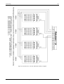
Setting Up and Programming Codepads For Partitioning .............................................................................................181
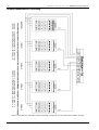
Codepad Connections For Partitioning .........................................................................................................................182
OPTIONAL EQUIPMENT................................................................................................................185
Optional Equipment ......................................................................................................................................................186
TERMINAL DEFINITIONS AND DESCRIPTIONS.....................................................................193
TERMINAL DEFINITIONS AND DESCRIPTIONS .....................................................................................................194
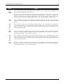
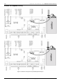
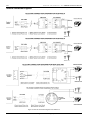
Solution-16 Wiring Diagram.........................................................................................................................................196
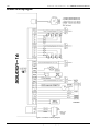
Eight Zone Expansion Board (CC885) - Fixed 3K3 EOL Resistors.............................................................................197
Eight Zone Expansion Board (CC883) - Variable EOL Resistors ................................................................................197
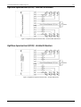
Connections Of Split EOL Resistors For 16 Zone Operation .......................................................................................198
Eight Channel Open Collector Output Board (CC884).................................................................................................198
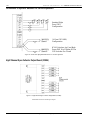
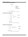
Connection For Momentary Or Latching Keyswitch ....................................................................................................199
Connections For 25 Pin Logging Printer.......................................................................................................................199
Connections For 9 Pin Logging Printer.........................................................................................................................199
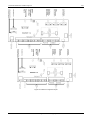
Solution-16 Component Overlay ..................................................................................................................................200
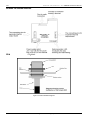
Solution-16 Safecom Interface......................................................................................................................................202
How To Install The BNC Fitting ..................................................................................................................................202
How To Mount The Radio............................................................................................................................................203
Mounting The Radio .....................................................................................................................................................203
Telecom Connection Diagrams.....................................................................................................................................204
APPENDICES .....................................................................................................................................205
APPENDIX A...................................................................................................................................................................206
Telephone Anti-Jamming ..........................................................................................................................................206
APPENDIX B...................................................................................................................................................................207
Test Reports Only When Armed ...............................................................................................................................207
SPECIFICATIONS.............................................................................................................................209
WARRANTY STATEMENT...........................................................................................................................................210
Specifications ............................................................................................................................................................210
Software Version Number.............................................................................................................................................210
PROGRAMMING SHEETS..............................................................................................................211
INDEX..................................................................................................................................................221
Introduction
14
Solution-16/Solution-16
Safecom Installation Manual
Introduction
Congratulations on selecting the Solution-16 control panel for your installation. So that you can obtain the most from
your unit, we suggest that you take the time to read through this manual and familiarise yourself with the numerous
outstanding operating and installation features of this control panel.
You will notice that in all aspects of planning, engineering, styling, operation, convenience and adaptability, we have sought
to anticipate your every possible requirement. Programming simplicity and speed have been some of the major
considerations and we believe that our objectives in this area have been more than satisfied.
This installation manual will explain all aspects of programming the Solution-16 control panel from factory default to
final commissioning. All system parameters and options are detailed, however, suitability is left up to the individual. Every
control panel can be tailored to meet all requirements quickly and easily. The programming simplicity will make your
installation quick, accurate and rewarding each and every time.
The Solution range of control panels has proven very popular amongst thousands of people throughout many countries
of the world, all who have various levels of technical aptitude and ability. We have tried to aim this installation manual to
all levels of readers.
As the Solution control panels have continued to advance over the years, they have become very powerful and extensive.
Some of its early first-time users have advanced to true "power users" and we need to address their needs too, while
maintaining the simplicity of the manual and the product.
ISSUE222.DOC
Electronics Design & Manufacturing Pty Limited
Introduction
15
Quick Start
The following steps will enable you to use the Solution-16 control panel with the factory default values.
1.
Connect the AC plug pack to the control panel.
All zone indicators on the remote codepad will illuminate momentarily and then extinguish. Check the operation of
the overload LED (LD1) on the printed circuit board. In normal operation the LED will not illuminate. The MAINS
indicator will remain on, as will the AWAY indicator. The system is now in the armed state.
2.
The lead acid back-up battery should now be connected. The lead acid rechargeable back-up battery should be rated
at 12v DC @ 6.5 Ah.
3.
Enter the
followed by the
button to disarm the system. The AWAY indicator will extinguish.
The control panel is now in the disarmed state. Programming of the control panel can now be accessed. Refer to the
"Master Code Functions" on page 50 for more information. The factory default Master Code is 2580.
4.
Enter the factory default
followed by the
button to access the Installer's Programming Mode.
The STAY and AWAY indicators will now flash simultaneously. Refer to "LOCATION 56 - 62" on page 98 for the
locations of the factory default Installer Code. The factory default Installer Code is 1234.
5.
Enter the Primary Telephone Number and the Secondary Telephone Number followed by the Subscriber ID Number.
6.
If required, program the test reporting time and any other programming changes to be made; otherwise the
programmed factory default settings will be used.
7.
Enter command 960 followed by the
button to exit the Installer's Programming Mode. The control panel
will return to the disarmed state and is now ready for use.
8.
Refer to page 42 for information on any system faults that may have occurred.
9.
Using a Master Code set the date and time. Refer to "Master Code Functions" on page 50 for more information on
setting the date and time.
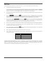
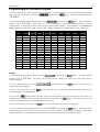
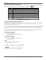
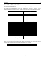
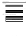
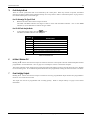
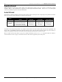
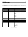
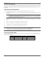
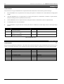
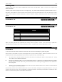
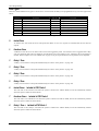
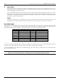
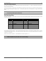
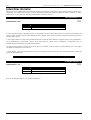
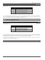
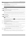
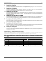
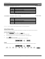
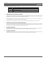
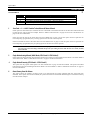
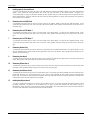
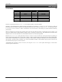
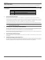
Zone Number
1
2, 3, 4, 5
6, 7 & 9 - 16
8
Zone Type
Delay-1
Handover
Instant
24 Hour
Table 1: Zone Defaults
The factory default settings allow the control panel to communicate in Contact ID Format operating eight zones. For further
information on the factory default settings, refer to the "Programming Sheets" on page 211 at the back of the installation
manual. If sixteen zones are required, refer to "LOCATION 339" on page 112 for setting the split EOL resistor value or
"LOCATION 672" to enable the zone expansion board if required on page 163.
Electronics Design & Manufacturing Pty Limited
ISSUE222.DOC
16
Solution-16/Solution-16
Safecom Installation Manual
Telepermit Note
The grant of a Telepermit for a device in no way indicates Telecom acceptance of responsibility for the correct operation of
that device under all operating conditions.
This equipment shall not be used in any manner that could constitute a nuisance to other Telecom customers.
Immediately disconnect this equipment should it become physically damaged, and arrange for its disposal or repair.
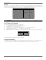
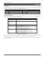
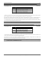
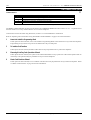
The preferred method of dialling is to use DTMF tones as this is faster than pulse (Decadic) dialling. In some situations
there may be difficulties with DTMF signalling as this control panel is not fully compatible with the Telecom Telephone
Network. In this case you must use decadic dialling, and your control panel must be set up to record numbers using the
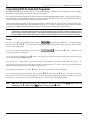
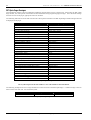
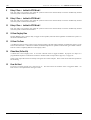
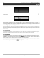
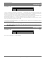
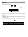
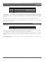
following translation table as it does not implement the New Zealand "Reverse Dialling" standard.
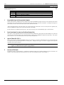
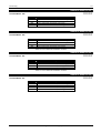
Number to be dialled
Number to be programmed
0
9
1
8
2
7
3
6
4
5
5
4
6
3
7
2
8
1
9
0
Note that where DTMF dialling is used, the numbers should be entered normally.
The transmit level from this device is set as a fixed level and because of this there may be circumstances where the
performance is less than optimal. Before reporting such occurrences as faults, please check the line with a standard
telepermitted telephone.
ISSUE222.DOC
Electronics Design & Manufacturing Pty Limited
Programming
18
Solution-16/Solution-16
Safecom Installation Manual
Programming
The programming options of this control panel are stored in a non-volatile EPROM. This memory will hold all the relevant
configuration and user specific data even during a total power loss.
The data retention time is as long as ten years without power, therefore, no reprogramming will be required after powering
the control panel down.
The data can be altered as many times as required without the need for any additional specialised equipment. This memory
is laid out in numerous locations, each of which holds the data for a specific function.
In general, the entire programming sequence will consist of nominating the location number required and then entering or
altering the data. You will repeat this procedure until all the data has been programmed to suit your requirements. The
factory default settings have been selected for reporting in the Contact ID Format.
Note:
15 is the maximum value that can be programmed into any location.
There are two programming modes. The Installer's Programming Mode and the Operators Programming Mode. Both
programming modes have individual access codes and these two codes must always be programmed differently. The
Master Code, as well as being able to arm and disarm the system gives access to the Operators Programming Mode. The
Installers Code only gives access to the Installer's Programming Mode and does NOT arm and disarm the system.
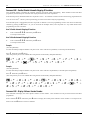
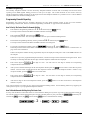
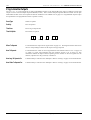
Programming of the Solution-16 control panel can be carried out via any of the following five methods.
ISSUE222.DOC
♦
System Codepad
♦
Hand Held Programmer (CC814)
♦
Programming Key (CC891)
♦
Alarm Link Upload/Download Software (CC816)
♦
DTMF Command Module (CC886)
Electronics Design & Manufacturing Pty Limited
Programming
19
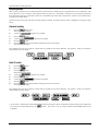
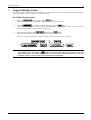
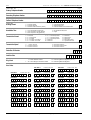
Programming With The Remote Codepad
The control panel must be in the disarmed state with no flashing zone alarm memories to access the Installer's Programming
followed by the
button. The factory default Master Code
Mode. This can be achieved by entering the
is 2580.
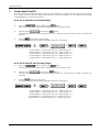
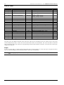
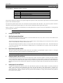
To access the Installer's Programming Mode, enter the
followed by the
button. The factory default
Installer Code is 1234. Three beeps will be heard and both the STAY and AWAY indicators will flash
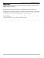
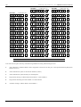
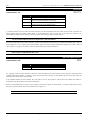
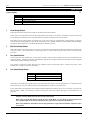
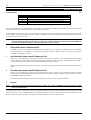
simultaneously. If a long beep is heard, check the control panel for alarm memory. The combination of the MAINS and
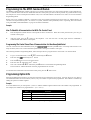
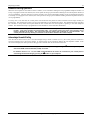
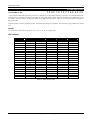
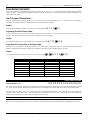
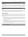
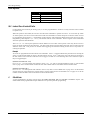
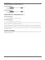
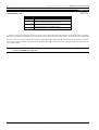
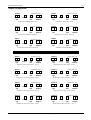
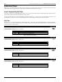
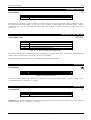
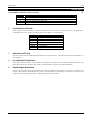
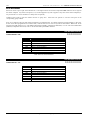
ZONE indicators will indicate the data stored in the first location of the Primary Telephone Number (LOCATION 000).
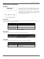
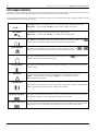
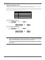
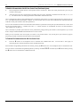
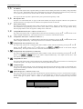
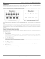
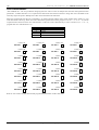
Data
Value
0
1
2
3
4
5
6
7
8
9
10
11
12
13
14
15
Zone 1
Indicator
Zone 2
Indicator
Zone 3
Indicator
Zone 4
Indicator
Zone 5
Indicator
Zone 6
Indicator
Zone 7
Indicator
Zone 8
Indicator
MAINS
Indicator
Table 2: Zone Indicators When Programming
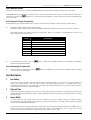
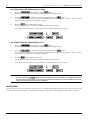
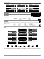
Example
To enter Installer's Programming Mode, enter the
Installer's Code is 1234.
"LOCATION 000".
followed by the
button. The factory default
Two beeps will be heard and the codepad will display the current data stored in
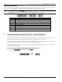
To go to a particular location, enter the
location will now be displayed.
To move to the next location, press the
will be displayed via the ZONE indicators.
required followed by the
button. The data of the new
button. This will step you to the next location and the data in that location
If you press the
button without previously entering a location number, the system will step back one location. To
button. This will store the new data
change data at the current location, enter the new value (0-15) followed by the
into the location and still leave you positioned at the same location.
To proceed to the next location, press the
button. The next locations data will now be displayed.
To exit the Installer's Programming Mode, enter command 960 followed by the
button. Two beeps will be
heard and the system will return back to normal operation. Refer to "Installers Programming Commands" on page 23 for
further information on commands that can be performed during access of the Installer's Programming Mode.
Electronics Design & Manufacturing Pty Limited
ISSUE222.DOC
20
Solution-16/Solution-16
Safecom Installation Manual
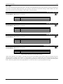
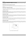
Programming With The Hand Held Programmer
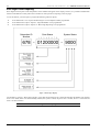
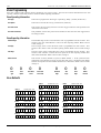
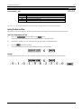
The Hand Held Programmer (CC814) has five, seven segment displays. The three on the left display the location number,
and the two on the right display the data for that particular location.
To connect the hand held programmer, locate the connections marked PROGRAMMING KEY. This point can be found on
the left hand side of the printed circuit board. Observe the triangular markings on the printed circuit board and line them up
with the markings on the hand held programmers connecting socket.
When the hand held programmer is correctly plugged onto the printed circuit board, one beep will be heard and four centre
bars on the hand held programmer will illuminate with either an 'A' or 'U' suffix to indicate the system is armed or unarmed.
Only when the Installer's Programming Mode has been accessed will any numerals appear on the display.
Note:
When connecting the hand held programmer to the control panel, make sure that the switch on the hand held
programmer is in the EXT position and that no external programming key has been connected. Failing to do this
may corrupt the control panel's memory. If this happens, the control panel will need to be returned to Electronics
Design and Manufacturing Pty Limited where a service fee will be charged to unlock the control panel’s memory.
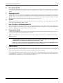
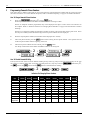
Example
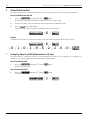
To enter the Installer's Programming Mode, enter the
followed by the
#
button. The factory default
Installers Code is 1234. Two beeps will be heard and the hand held programmers display will show the current data
stored in "LOCATION 000".
To move to a particular programming location, enter the
new location will now be displayed.
followed by the # button.
The data for the
To move to the next location press the # button. This will step you to the next location and the data in that location will
now be displayed via the ZONE indicators.
* button without previously entering a location number, the system will step back one location. To
change data in the current location, enter the new value (0-15) followed by the * button. This will store the new data into
If you press the
the location and still leave you still positioned at the same location.
To proceed to the next location, press the # button. The next locations data will now be displayed.
To exit the Installer's Programming Mode, enter command 960 followed by the # button. Two beeps will be heard
and the system will return back to normal operation. Refer to "Installers Programming Commands" on page 23 for further
information on commands that can be performed during access of the Installer's Programming Mode.
Note:
When using the hand held programmer, any reference in this manual made to the
considered as the * button and the
ISSUE222.DOC
button considered as the # button.
Electronics Design & Manufacturing Pty Limited
button should be
Programming
21
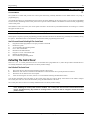
Programming Using The Programming Key
The Programming Key (CC891) is a unique device that will allow you to easily program your control panel. Inserting the
programming key will automatically initiate a data transfer from the programming key to the control panel memory.
If you have a new programming key, you should first enter the Installer's Programming Mode, configure your control panel as per
your requirements before inserting the programming key.
To connect the programming key, locate the connections marked PROGRAMMING KEY. This point can be found on the right
hand side of the control panel. Observe the triangular markings on the printed circuit board and line them up with the markings
on the programming key.
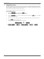
To copy the control panel's data into your new programming key, enter command 962 followed by the
to "Command 962 - Copy Control Panel Memory To Programming Key" on page 25 for further details.
button. Refer
Exit the Installer's Programming Mode by entering the command 960 followed by the
button, wait two seconds for
the activity LED to return to its normal state and then remove the programming key. This programming key will now become your
standard data pattern for future programming of your control panels.
It should be noted that when entering the Installer's Programming Mode, inserting a programming key and then altering any
location would cause a simultaneous update of not only the programming keys data, but also the control panel’s data. Therefore,
you are not able to alter data in the programming key without the same location being altered in the control panel’s memory.
Note:
Connecting a Programming Key (CC891) to the control panel when the programming keys memory is blank will
corrupt the control panel's memory unless the Installer's Programming Mode has been entered first. If this
occurs, then the control panel will need to be returned to Electronics Design & Manufacturing Pty Limited where a
service fee will be charged to unlock the control panel’s memory.
Electronics Design & Manufacturing Pty Limited
ISSUE222.DOC
22
Solution-16/Solution-16
Safecom Installation Manual
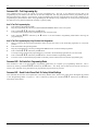
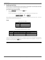
Programming Via The DTMF Command Module
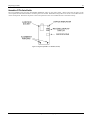
The DTMF Command Module (CC886) will allow you to operate and program your control panel remotely via the telephone line.
Once a communications link has been established with the control panel, you will be able to perform any system functions using
the codepad on a touch tone telephone for Master Code, User Code and Installer Code Functions as well as access into Installer's
Programming Mode.
Below will give an example of making a connection to the control panel and changing the "Exit Time" for AWAY Mode to 26
seconds on a non-partitioned system. To connect to a system, which has been partitioned, refer to "Operating The Control Panel
Using The DTMF Command Module" on page 67 for further information.
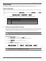
Example
How To Establish A Communication Link With The Control Panel
1.
2.
Dial the telephone number that the control panel has been connected to. When the control panel answers your call, you
will hear a short jingle.
After the jingle, press the 0 button on the telephone. You will now hear a second jingle and have established a
communication link with the control panel.
Programming The Control Panel Once A Communication Link Has Been Established
Once the connection has been established, enter your
followed by the # button. Two beeps will be heard.
If no
beeps are heard, enter a user code to disarm the system before entering the Installer's Code again.
After entering Installer's Programming Mode, follow the steps below to program the new "Exit Time " for AWAY Mode.
1.
To go to "LOCATION 632", enter 632 followed by the # button.
2.
Enter the value
3.
Press the # button to move to the next location.
4.
Enter the value 1 followed by the * button.
5.
Now enter command 960 followed by the # button to exit Installer's Programming Mode.
The exit time for AWAY Mode has now been programmed for 26 seconds.
followed by the * button.
To terminate the communication link with the control panel, press the # button twice.
Programming Option Bits
When programming these locations you will notice that there are four alternatives per location. You may select one, two, three or
all of these alternatives for each location, however, only one number is required to be programmed. This number is calculated by
adding the option bit numbers together.
Example
If at "LOCATION 663" you want options 1, 2 and 4. Add the numbers together and the total is the number to be programmed. In
this example, the number to be programmed is 7 (i.e. 1+2+4=7).
Option
1
2
4
8
Description
Enable Dialler Reporting Functions
Enable Remote Arming Via The Telephone
Enable Upload/Download
Terminate Alarm Link Session On Alarm
Table 3: Example - Programming Option Bits
ISSUE222.DOC
Electronics Design & Manufacturing Pty Limited
Programming
23
Installers Programming Commands
There are several commands that can be invoked to perform various functions once the Installer's Programming Mode has been
entered. To invoke the command, enter the corresponding numerical code followed by the
Command
958
959
960
961
962
963
964
965
966
999
button
Function
Enable and Disable Zone Status Mode
Test Programming Key
Exit Installer’s Programming Mode
Reset Control Panel Back To Factory Default Settings
Copy The Control Panel Memory To The Programming Key
Copy The Programming Key Data To The Control Panel
Erase Programming Key
Set Up Domestic Dialling Format
Enable and Disable Automatic Stepping Of Locations During Programming
This Command Displays The Control Panel’s Software Version Number Only When
Using The Hand Held Programmer
Table 4: Installer's Programming Commands
Command 958 - Enable/Disable Zone Status Mode
This function enables and disables the zone status display mode. When using the hand held programmer, the zones will be
displayed on the seven segment displays from left to right. If there is a dash illuminated on the display, the corresponding zone is
unsealed and if the display is blank, the zone is sealed.
The third (or centre) display shows either the number 4 or the number 8. The number 4 constantly illuminated indicates that
zones 1 - 4 are being displayed. The number 8 constantly illuminated indicates that zones 5 - 8 are being displayed. The number
4 flashing indicates zones 9 - 12 are being displayed. The number 8 flashing indicates that zones 13 - 16 are being displayed.
Pressing the # button will toggle the display between the zones. This feature will prove to be very useful during installation as
it allows you to view the status of the zones directly at the control panel, saving you time and money.
How To Enable Zone Status Mode
1.
Enter Installers Programming Mode.
2.
Enter command 958 followed by the # button.
Two beeps will be heard.
How To Disable Zone Status Mode
1.
Enter command 958 followed by the # button.
Two beeps will be heard.
Example
A " - " in the display indicates the zone is triggered.
A blank display indicates the zone is normal.
--4--
indicates that zones 1, 2, 3 and 4 are triggered.
A flashing "4" indicates zones 9, 10, 11 and 12 are being displayed.
-¤
¤8¤
¤-
indicates that zones 5 and 8 are triggered.
A flashing "8" indicates zones 13 and 16 are being displayed.
Electronics Design & Manufacturing Pty Limited
ISSUE222.DOC
24
Solution-16/Solution-16
Safecom Installation Manual
Command 959 - Test Programming Key
This command causes a test to be carried out on the programming key. This test is non destructive and any data in the
programming key will remain intact after the test has been completed. One long beep indicates that the programming key has
failed and three beeps indicate a successful test. If the programming key has been removed before the test has completed or the
programming key has failed, the data in the programming key has become corrupt. Remember, do not remove the programming
key while the activity LED is illuminated constantly or pulsing rapidly.
How To Test The Programming Key
1.
2.
Enter Installer's Programming Mode.
Plug the programming key onto the pins marked PROGRAMMING KEY on the control panel.
3.
Enter command 959 followed by the # button.
Two beeps will be heard and the programming key has now been tested.
4.
Enter command 960 followed by the
programming key.
#
button to exit the Installer's Programming Mode before removing the
How To Test The Programming Key Using The Hand Held Programmer
1.
2.
3.
Before connecting the hand held programmer, make sure that the switch on the hand held programmer is in the EXT
position.
Enter the Installer's Programming Mode.
Plug the programming key onto the pins marked EXTERNAL KEY on the hand held programmer.
4.
Enter command 959 followed by the # button.
Two beeps will be heard and the programming key connected to the hand held programmer has now been tested.
5.
6.
Enter command 960 followed by the # button to exit the Installer's Programming Mode.
Leave the switch on the hand held programmer in the EXT position and disconnect the external programming key.
Command 960 - Exit Installer's Programming Mode
This command is used to exit the Installer's Programming Mode after you complete your programming alterations. This is
achieved by entering command 960 followed by the # button. Two beeps will be heard and the system will return to
normal. This command can be performed at any programming stage and from any location.
Command 961 - Reset Control Panel Back To Factory Default Settings
This command will reset the control panel back to the factory default values. Refer to the values shown throughout this manual
or the “Programming Sheets” on page 211. This is achieved by entering the command
Three beeps will be heard.
ISSUE222.DOC
Electronics Design & Manufacturing Pty Limited
961 followed by the # button.
Programming
25
Command 962 - Copy Control Panel Memory To Programming Key
This command is used to copy the control panel memory to the programming key.
How To Copy The Control Panel Memory To The Programming Key
1.
2.
Enter Installer's Programming Mode.
Plug the programming key onto the pins marked PROGRAMMING KEY on the control panel.
3.
Enter command 962 followed by the # button.
Two beeps will be heard and the control panel’s memory has now been copied into the programming key.
4.
5.
Enter command 960 followed by the # button to exit the Installer's Programming Mode.
Disconnect the programming key from the control panel.
How To Copy The Control Panel Memory To The Programming Key Using The Hand Held Programmer
1.
2.
3.
Before connecting the hand held programmer to the control panel, make sure that the switch on the hand held programmer
is in the EXT position.
Enter the Installer's Programming Mode.
Plug the programming key onto the pins marked EXTERNAL KEY on the hand held programmer.
4.
Enter command 962 followed by the # button.
Two beeps will be heard and the control panel's memory has now been copied into the programming key.
5.
6.
Enter command 960 followed by the # button to exit the Installer's Programming Mode.
Leave the switch on the hand held programmer in the EXT position and disconnect the programming key.
Command 963 - Copy From Programming Key To Control Panel
This command is used to copy data from the programming key to the control panel.
How To Copy The Programming Key Memory To The Control Panel
1.
2.
Enter Installer's Programming Mode.
Connect the programming key onto the pins marked PROGRAMMING KEY on the control panel.
3.
Enter command 963 followed by the # button.
Two beeps will be heard and the programming key's data has now been copied to the control panel.
4.
5.
Enter command 960 followed by the # button to exit Installer's Programming Mode.
Now disconnect the programming key from the control panel.
How To Copy The Programming Key Memory To The Control Panel Using The Hand Held Programmer
1.
2.
3.
Before connecting the hand held programmer to the control panel, make sure that the switch on the hand held programmer
is in the EXT position.
Enter the Installer's Programming Mode.
Plug the programming key onto the pins marked EXTERNAL KEY on the hand held programmer.
4.
Enter command 963 followed by the # button.
Two beeps will be heard and the programming keys data will now be copied to the control panel.
5.
6.
Enter command 960 followed by the # button to exit the Installer's Programming Mode.
Leave the switch on the hand held programmer in the EXT position and disconnect the programming key.
Electronics Design & Manufacturing Pty Limited
ISSUE222.DOC
26
Solution-16/Solution-16
Safecom Installation Manual
Command 964 - Erase Programming Key
This command erases all data from the programming key.
How To Erase The Programming Key
1.
2.
Enter the Installer's Programming Mode.
Connect the programming key onto the pins marked PROGRAMMING KEY on the control panel.
3.
4.
Enter command 964 followed by the # button.
Two beeps will be heard and the programming keys data has now been deleted.
5.
6.
Enter command 960 followed by the # button to exit the Installer's Programming Mode.
Now remove the programming key from the control panel.
How To Erase The Programming Key Using The Hand Held Programmer
1.
2.
3.
Before connecting the hand held programmer to the control panel, make sure that the switch on the hand held programmer
is in the EXT position.
Enter the Installer's Programming Mode.
Plug the programming key onto the pins marked EXTERNAL KEY on the hand held programmer.
4.
Enter command 964 followed by the # button.
Two beeps will be heard and the programming keys data has now been deleted.
5.
6.
Enter command 960 followed by the # button to exit Installer's Programming Mode.
Now disconnect the programming key from the hand held programmer.
ISSUE222.DOC
Electronics Design & Manufacturing Pty Limited
Programming
27
Command 965 - Set Up Domestic Dialling Format
Command 965 has been added to make the set up of the Domestic Dialling Format a one step operation. Refer to page 78 for
more information on "Domestic Reporting".
After Installer's Programming Mode has been accessed, enter command 965 followed by the # button. This will
automatically set the following locations in bold below. No other locations will be altered when command 965 has been issued.
Location
Location 49
Location 50
Location 52 - 55
Location 340 - 347
Location 348 - 355
Location 356 - 363
Location 364 - 371
Location 372 - 379
Location 380 - 387
Location 388 - 395
Location 396 - 403
Location 404 - 411
Location 412 - 419
Location 420 - 427
Location 428 - 435
Location 436 - 443
Location 444 - 451
Location 452 - 459
Location 460 - 467
Location 468 - 471
Location 472 - 475
Location 476 - 479
Location 480 - 483
Location 484 - 487
Location 488 - 491
Location 492 - 495
Location 496 - 499
Location 500 - 503
Location 504 - 505
Location 506 - 513
Description
Handshake Tone
Transmission Format
Subscriber ID Number
Zone 1
Zone 2
Zone 3
Zone 4
Zone 5
Zone 6
Zone 7
Zone 8
Zone 9
Zone 10
Zone 11
Zone 12
Zone 13
Zone 14
Zone 15
Zone 16
Bypass Reports
Trouble Reports
Codepad Duress
Codepad Panic
Codepad Tamper
AC Fail
Low Battery
Program Altered
Sensor Watch
Open/Close Reports
Test Report Time
Setting
2 (1400 Hz)
11 (Domestic Dialling)
0, 0, 0, 1
2, 0, 0, 0, 0, 3, 0, 1 (Delay-1)
1, 0, 0, 0, 0, 3, 0, 1 (Handover)
1, 0, 0, 0, 0, 3, 0, 1 (Handover)
1, 0, 0, 0, 0, 3, 0, 1 (Handover)
1, 0, 0, 0, 0, 3, 0, 1 (Handover)
0, 0, 0, 0, 0, 3, 0, 1 (Instant)
0, 0, 0, 0, 0, 3, 0, 1 (Instant)
12, 0, 0, 0, 0, 3, 3, 1 (24 Hour Burglary)
0, 0, 0, 0, 0, 3, 0, 1 (Instant)
0, 0, 0, 0, 0, 3, 0, 1 (Instant)
0, 0, 0, 0, 0, 3, 0, 1 (Instant)
0, 0, 0, 0, 0, 3, 0, 1 (Instant)
0, 0, 0, 0, 0, 3, 0, 1 (Instant)
0, 0, 0, 0, 0, 3, 0, 1 (Instant)
0, 0, 0, 0, 0, 3, 0, 1 (Instant)
0, 0, 0, 0, 0, 3, 0, 1 (Instant)
0, 0, 0, 0
(Not Used)
0, 0, 0, 0
(Not Used)
0, 0, 0, 0
(Not Used)
0, 0, 0, 0
(Not Used)
0, 0, 0, 0
(Not Used)
0, 0, 0, 0
(Not Used)
0, 0, 0, 0
(Not Used)
0, 0, 0, 0
(Not Used)
0, 0, 0, 0
(Not Used)
0, 0
(Not Used)
0, 0, 0, 0, 0, 0, 9, 0 (Not Used)
Table 5: Command 965 Defaults
As you can see from the table above, all reporting other than zone alarms have been disabled. The handshake tone has been set
for 1400 Hz tone acknowledgment and the Subscriber ID Number has been set for one identification beep. The zone reporting
has been set so that any zone that triggers into alarm condition will only report when the alarm occurs, the zone restore report will
not report as there is no separate indications for zone alarm reports and zone alarm restore reports.
Note:
From Software Version 1.30, Command 965 disables zone restore reports.
Electronics Design & Manufacturing Pty Limited
ISSUE222.DOC
28
Solution-16/Solution-16
Safecom Installation Manual
Command 966 - Enable/Disable Automatic Stepping Of Locations
This command enables or disables the automatic stepping of locations while programming. When enabled via the hand held
programmer, the decimal point of the left most display will reflect the mode of operation.
If the decimal point is illuminated then auto step mode is active. An automatic increment of the location being programmed will
occur as soon as the * button is pressed positioning you at the next location ready for programming.
If the decimal point is extinguished, the auto step mode is disabled. The next programming location will need to be manually
selected by pressing the # button. As you can see from the examples below, auto step mode is a very useful feature when
programming successive locations.
How To Enable Automatic Stepping Of Locations
1.
Enter command 966 followed by the # button.
Two beeps will be heard.
How To Disable Automatic Stepping Of Locations
1.
Enter command 966 followed by the # button.
Two beeps will be heard.
Example
(Auto Step Enabled)
To enter the Primary Telephone Number "02 pause 9 672 1055" with auto step enabled (i.e. Decimal point illuminated).
Press 0 followed by the # button.
(This will position you at "LOCATION 000" being the start of the Primary Telephone Number).
+*+2+*+
+*+9+*+6+*+7+*+2+
+*+5+*+5+*+0+*
*+1+*+
Example
(Auto Step Disabled)
To enter the Primary Telephone Number "02 pause 9 672 1055" with auto step disabled (i.e. Decimal point extinguished).
Press 0 followed by the # button.
(This will position you at "LOCATION 000" being the start of the Primary Telephone Number).
+*+#+2+*+#+
+*+#+9+*+#+6+
+*+
*+#+7+*+#+2+*+#+1+*+#+
#+5+*+#+5+*+#+0+*
Command 999 - Display Software Version Number
This command will display the control panel's software version number. This command can only be used with the hand held
programmer.
999 followed by the # button to display the control panel's software version number.
Press the # button to exit this command.
Enter command
heard.
ISSUE222.DOC
Electronics Design & Manufacturing Pty Limited
Two beeps will be
Programming
29
Disable Factory Default
0
LOCATION 900
The system has a feature that prevents the control panel from being manually defaulted via the default button or by using a
programming key.
Any number between 0-14 programmed into this location will allow defaulting of the control panel. If 15 has been programmed
into this location, defaulting of the control panel will not operate and the Installer Code MUST be used for further programming
of the control panel.
If the Installer Code is not known, the control panel will need to be returned to your EDM Distributor for exchange. A nominal
fee applies for this service.
Warning:
Electronics Design and Manufacturing Pty Limited does not recommend the use of this feature.
If this option is required, a special programming procedure has been introduced to eliminate any possibility of accidentally setting
this option. The default button on the PCB must be held down while programming this location.
How To Prevent Manual Defaulting Of The Control Panel
1.
2.
3.
4.
5.
6.
7.
8.
Plug the hand held programmer to the pins provided on the PCB.
Disarm the system.
Access Installer's Programming Mode.
Go to "LOCATION 900".
Hold down the default button.
Program a 15 into "LOCATION 900".
Release the default button.
Exit Installer's Programming Mode.
Defaulting The Control Panel
If the Solution-16 control panel does not have "LOCATION 900" programmed as 15, follow the procedure outlined below to
successfully default the control panel back to the factory default settings.
How To Default The Control Panel
1.
2.
3.
4.
Disconnect the AC mains and backup battery from the control panel.
Hold down and continue to hold down the DEFAULT button located at the top of the printed circuit board.
Reconnect the AC mains to the control panel.
After reconnecting the AC mains, wait for 3-5 seconds before releasing the DEFAULT button.
You will hear the dialler seize relay (RL2) on the control panel click once and two beeps will be heard on the remote codepad.
The control panel will now need to be disarmed by using the default Master Code 2580.
The control panel has now been successfully defaulted back to the factory default settings.
Note:
If following the above procedure to default the control panel and you hear the dialler seize relay (RL2) click four
times, defaulting the control panel has been disabled. The control panel will need to be returned to Electronics
Design and Manufacturing Pty Limited for exchange where a service fee will be charged to unlock the control
panel's memory.
Electronics Design & Manufacturing Pty Limited
ISSUE222.DOC
30
ISSUE222.DOC
Solution-16/Solution-16
Electronics Design & Manufacturing Pty Limited
Safecom Installation Manual
System Indicators and Operations
32
Solution-16/Solution-16
Safecom Installation Manual
System Indicators and Operations
The Codepad
The codepad is the communications interface between you and your
alarm system. It allows you to issue commands and offers both visual
and audible indications that guide you through the general operation.
The codepad incorporates numerous indicators. There are ZONE
indicators that are used to show the condition of each zone and four
others for general status. The following is a list of situations and the
relevant indications that will be seen.
Figure 1: CP5 Eight Zone Codepad
Zone Indicators
The ZONE indicators are used to show the status of the zones. The following table list the various circumstances that the
indicators will display (i.e. Zone Sealed, Zone Unsealed).
Indicator
On
Off
Flashing Fast
(0.25 Sec On - 0.25 Sec Off)
Flashing Slow
(1 Sec On - 1 Sec Off)
Definition
Zone Is Unsealed
Zone Is Sealed
Zone Is In Alarm Condition
Zone Is Manually Isolated
Table 6: Zone Indicators
AWAY Indicator
The AWAY indicator is used to inform you that the system is armed in the AWAY Mode.
Indicator
On
Off
Definition
System Is Armed In AWAY Mode
System Is Not Armed In AWAY Mode
Table 7: AWAY Indicator Functions
STAY Indicator
The STAY indicator is used to indicate that the system is armed in STAY Mode 1 or STAY Mode 2.
Indicator
On
Off
Flashing
Definition
System Is Armed In STAY Mode 1 Or STAY Mode 2
System Is Not Armed In STAY Mode 1 Or STAY Mode 2
System Is In ISOLATE Mode Or STAY Mode 2 Zones Are
Being Programmed
Table 8: STAY Indicator Functions
ISSUE222.DOC
Electronics Design & Manufacturing Pty Limited
System Indicators and Operations
33
MAINS Indicator
The MAINS indicator is used to indicate that the systems AC mains power is normal or has failed.
Indicator
On
Flashing
Definition
AC Mains Power Normal
AC Mains Failure
Table 9: MAINS Indicator Function
FAULT Indicator
The FAULT indicator is used to indicate that the system has detected a system fault. Refer to "Fault Analysis Mode" on page 42
for more details on system faults.
Indicator
On
Off
Flashing
Definition
There Is A System Fault That Needs To Be Rectified
The System Is Normal, There Are No Faults
There Is A System Fault Waiting To Be Acknowledged
Table 10: FAULT Indicator Functions
Audible Indicators
In general, the audible indications given out by the codepad are as follows:
Indicator
One Short Beep
Two Short Beeps
Three Short Beeps
One Long Beep
One Short Beep Every Second
One Short Beep Every Minute
Definition
A Button Has Been Pressed On The Codepad Or End Of
Exit Time In STAY Mode 1 or STAY Mode 2
The System Has Accepted Your Code
The Requested Function Has Been Executed
Indicates The End Of Exit Time In AWAY Mode Or
The Requested Operation Has Been Denied Or Aborted
Walk Test Mode Is Currently Active Or Warning Before
Automatic Arming Takes Place
There Is A System Fault Waiting To Be Acknowledged
Table 11: Audible Indications
Electronics Design & Manufacturing Pty Limited
ISSUE222.DOC
34
Solution-16/Solution-16
Safecom Installation Manual
LCD Codepad Indicators
The LCD fixed icon codepads provide full zone status indication at all times as well as a number of special icons which indicate
such things as system armed, system disarmed, mains fail, system fault and other system functions.
The following table outlines all of the indicators that will be found on the “CP5 Eight Zone LCD Codepad (CP508L)” and the
“CP5 Sixteen Zone LCD Codepad (CP516L)”.
Zone Indicators!
"!#!$ ….
Mains Indicator
Armed In AWAY Mode
Armed In STAY Mode
System Disarmed
Zone Isolating Mode
Fault Indicator
The ZONE indicators (1-8 on CP508L and 1-16 on CP516L) show the status of each zone.
Illuminated = Zone Unsealed Flashing = Zone In Alarm Off = Zone Sealed
The MAINS icon indicates the status of the AC mains power supply.
Illuminated = AC Mains OK Flashing = AC Mains Disconnected Or Fail
The AWAY icon illuminates when the system is armed in the AWAY mode. The
indicator will also illuminate when the system is armed in the AWAY mode.
The STAY icon illuminates when the system is armed in the STAY mode. The
indicators will also illuminate when the system is armed in the STAY mode.
This icon will illuminate when the system has been disarmed. The
illuminate when the system has been disarmed.
and
indicator will also
This indicator will illuminate when you attempt to isolate zones. The person will flash once
every 3 seconds.
The FAULT icon will illuminate if the control panel has registered a fault condition.
Steady = A fault has been acknowledged. Flashing = A new fault has occurred.
Off = No faults have occurred.
Programming Mode
This indicator will illuminate when the system has entered either Installer’s Programming
Mode or Operators Programming Mode. Both persons will flash.
Flashing
Off Indicator / Zone Sealed
On Indicator / Zone In Alarm
The OFF icon will illuminate when the system is in the disarmed state and will flash when a
zone becomes unsealed. It will stop flashing when all zones are sealed.
The ON icon will illuminate when the system is armed in the AWAY mode and will flash
when an alarm occurs. The indicator will reset once a valid user code has been entered.
Table 12: ICON Indicators and Descriptions
ISSUE222.DOC
Electronics Design & Manufacturing Pty Limited
System Indicators and Operations
35
System Operations
Arming The System In AWAY Mode
There are two methods for arming your system in the AWAY Mode. Method one is standard and will always operate. Method
two is optional and requires to be enabled in "LOCATION 670" on page 161.
Note:
Single button arming in AWAY Mode will report as user code number 32.
Method One
How To Arm The System In AWAY Mode
1.
Enter your
followed by the
button.
Two beeps will be heard and the AWAY indicator will illuminate. Exit time will now begin.
+
Method Two
How To Arm The System In AWAY Mode
1.
Hold down the
button until two beeps are heard.
The AWAY indicator will illuminate and exit time will now begin. Refer to Option 2 in "LOCATION 670" on page 161 to
enable "Single Button Arming Allowed (AWAY Mode, STAY Mode 1 & STAY Mode 2".
If a zone is not sealed at the end of exit time the zone will be automatically isolated. It will become an active part of the system
again as soon as it has resealed (i.e. If a window is left open after exit time has expired, the window will not be an active part of
the system until it has closed. Opening the window after exit time has expired will cause an alarm condition).
Forced Arming
The feature of arming the system when a zone is not sealed is known as forced arming. To enable forced arming, Option 1 in
"LOCATION 665" on page 154 will need to be enabled.
If the AWAY indicator does not illuminate and a long beep is heard, forced arming is not permitted. If this is the case you must
ensure that all zones are sealed or manually isolated before you can arm the system.
Disarming The System From AWAY Mode
How To Disarm The System From AWAY Mode
1.
Enter your
followed by the
button.
Two beeps will be heard and the AWAY indicator will extinguish. A flashing ZONE indicator represents a previous alarm
on that zone.
+
Electronics Design & Manufacturing Pty Limited
ISSUE222.DOC
36
Solution-16/Solution-16
Safecom Installation Manual
Arming The System In STAY Mode 1
STAY Mode 1 is when the system has been armed with particular zones automatically isolated. These zones can only be
programmed by the installer.
When there is a need to arm only the system perimeter, this mode is extremely handy. It automatically disables the interior
detection zones for allowing movement within the protected area while at the same time arming the perimeter zones.
There are two methods for arming your system in STAY Mode 1. Method one is standard and will always operate. Method two
is optional and needs to be enabled in "LOCATION 670" on page 161.
Note:
Single button arming in STAY Mode 1 will report as user code number 32.
Method One
How To Arm The System In STAY Mode 1
1.
Enter your
followed by the
button.
Two beeps will be heard and the STAY indicator will illuminate. Exit time for STAY Mode 1 will now commence.
Any zones that have been programmed for STAY Mode 1 will be automatically isolated and their respective indicators will begin
to flash until exit time expires. At the end of exit time, the ZONE indicators will extinguish and the codepad will give one short
beep.
+
Method Two
How To Arm The System In STAY Mode 1
1.
Hold down the
button until two beeps are heard.
The STAY indicator will illuminate and exit time for STAY Mode 1 will now commence.
Any zone that have been programmed for STAY Mode 1 will be automatically isolated and their respective indicators will begin
to flash until exit time expires. At the end of exit time, the zone indicators will extinguish and the codepad will give one short
beep.
If a zone is not sealed at the end of exit time the zone will be automatically isolated. It will become an active part of the system
again as soon as it has resealed (i.e. If a window is left open after exit time has expired, the window will not be an active part of
the system until it has closed. Opening the window after exit time has expired will cause an alarm condition).
Forced Arming
The feature of arming the system when a zone is not sealed is known as forced arming. To enable forced arming, Option 1 in
"LOCATION 665" on page 154 will need to be enabled.
If the STAY indicator does not illuminate and a long beep is heard, forced arming is not permitted. If this is the case, you must
ensure that all zones are sealed or manually isolated before you can arm the system.
ISSUE222.DOC
Electronics Design & Manufacturing Pty Limited
System Indicators and Operations
37
Disarming The System From STAY Mode 1
There are two methods for disarming the system from STAY Mode 1. Method one is standard and will always operate. Method
two is optional and requires to be enabled in "LOCATION 670" on page 161.
Note:
Method two will not operate unless "Single Button Arming Allowed (AWAY Mode, STAY Mode 1 & STAY Mode 2"
has been enabled.
Method One
How To Disarm The System From STAY Mode 1
1.
Enter your
followed by the
button.
Two beeps will be heard and the STAY indicator will extinguish. A flashing ZONE indicator represents a previous alarm
on that zone.
+
OR
+
Method Two
A flashing ZONE indicator represents a previous alarm on that zone. If this is the case a valid user code will need to be used to
disarm the system. To enable method two, Option 4 in "LOCATION 670" on page 161 will need to be enabled.
Note:
Single button disarming from STAY Mode 1 will report as user code number 32.
How To Disarm The System From STAY Mode 1
1.
Hold down the
button until two beeps are heard.
The STAY indicator will extinguish and the system will be disarmed.
Electronics Design & Manufacturing Pty Limited
ISSUE222.DOC
38
Solution-16/Solution-16
Safecom Installation Manual
Arming The System In STAY Mode 2
STAY Mode 2 is when the system has been armed with particular zones automatically isolated. These zones are programmed via
the Master Code holder.
When there is a need to arm the system perimeter only, this mode is extremely handy. It automatically disables the interior
detection zones allowing for movement within the protected area while at the same time arming the perimeter zones.
For STAY Mode 2 to operate, Option 2 in "LOCATION 670" on page 161 will need to be enabled. Refer to the Master Code
Function - “Setting STAY Mode 2 Zones” on page 59 for further information on programming zones for STAY Mode 2.
Note:
Single button arming in STAY Mode 2 will report as user code number 32.
How To Arm The System In STAY Mode 2
1.
Hold down the 0 button until two beeps are heard.
The STAY indicator will illuminate and exit time for STAY Mode 2 will now commence.
Any zone that has been programmed for STAY Mode 2 will be automatically isolated and their respective indicators will begin to
flash until exit time expires. At the end of exit time, the ZONE indicators will extinguish and the codepad will give one short
beep.
0
If a zone is not sealed at the end of exit time the zone will be automatically isolated. It will become an active part of the system
again as soon as it has resealed (i.e. If a window is left open after exit time has expired, the window will not be an active part of
the system until it has closed. Opening the window after exit time has expired will cause an alarm condition).
Forced Arming
The feature of arming the system when a zone is not sealed is known as forced arming. To enable forced arming, Option 1 in
"LOCATION 665" on page 154 will need to be enabled.
If the STAY indicator does not illuminate and a long beep is heard, forced arming is not permitted. If this is the case, you must
ensure that all zones are sealed or manually isolated before you can arm the system.
ISSUE222.DOC
Electronics Design & Manufacturing Pty Limited
System Indicators and Operations
39
Disarming The System From STAY Mode 2
There are two methods for disarming the system from STAY Mode 2. Method one is standard and will always operate. Method
two is optional and requires to be enabled in "LOCATION 670" on page 161.
Note:
Method two will not operate unless "Single Button Arming Allowed (AWAY Mode, STAY Mode 1 & STAY Mode 2"
has also been enabled.
Method One
How To Disarm The System From STAY Mode 2
1.
Enter your
followed by the
button.
Two beeps will be heard and the STAY indicator will extinguish. A flashing ZONE indicator represents a previous alarm
on that zone.
+
OR
+
Method Two
A flashing ZONE indicator represents a previous alarm on that zone. If this is the case, a valid user code will need to be used to
disarm the system. To enable method two, Option 4 in "LOCATION 670" on page 161 will need to be enabled.
How To Disarm The System From STAY Mode 2
1.
Hold down button 0 until two beeps are heard.
The STAY indicator will extinguish and the system will be disarmed.
0
Electronics Design & Manufacturing Pty Limited
ISSUE222.DOC
40
Solution-16/Solution-16
Safecom Installation Manual
Codepad Duress Alarm
A codepad duress alarm can be used as a hold up alarm. This will occur when the number 9 is added to the end of any valid
user code that is being used to disarm the system. A duress alarm is always silent and can only be made use of if your system is
reporting back to a monitoring station or pocket pager.
+9+
Codepad Panic Alarm - Software Version 1.10 - 1.36
A codepad panic alarm will be triggered when any two outside buttons in the same horizontal row on the remote codepad are
pressed simultaneously. This is an audible alarm. Refer to Option 4 in "LOCATION 666" on page 155 to enable codepad panic
to be silent.
+
or
1 + 3 or 4 + 6 or 7 + 9
Codepad Panic Alarm - Software Version 1.37 +
A codepad panic alarm will be triggered when either the 1 and 3 buttons or the
and
buttons are pressed
simultaneously. This is an audible alarm. Refer to Option 4 in "LOCATION 666" on page 155 to enable codepad panic to be
silent.
1 + 3 or
+
Codepad Fire Alarm - Software Version 1.37 +
A codepad fire alarm will be triggered when the 4 and 6 buttons on the remote codepad are pressed simultaneously. This is an
audible alarm. A distinct fire sound is emitted through the horn speaker to indicate this type of alarm condition. The fire sound is
different to the burglary sound.
4+6
Codepad Medical Alarm - Software Version 1.37+
A codepad medical alarm will be triggered when the
audible alarm.
7 and 9 buttons on the codepad are pressed simultaneously.
This is an
7+9
Note:
To disable both the reporting and the audible alarms for codepad panic, codepad fire and codepad medical
alarms, the following will need to be programmed.
In "LOCATION 666" on page 155, "Option 2 - Enable Codepad Panic To Be Silent" will need to be enabled. You
will also need to program "LOCATION 483" on page 117 as 0.
ISSUE222.DOC
Electronics Design & Manufacturing Pty Limited
System Indicators and Operations
41
Isolating Zones
When a zone is isolated, access is allowed into that zone at all times. Isolating zones is performed by one of two methods. One
way requires the use of a valid user code while the other way does not. The ability to isolate zones is governed by the priority
level allocated to each user code holder. Some user code holders may not be able to isolate zones. Refer to "User Code Priority"
on page 99 for further details.
Twenty-four hour zone types and zones not used cannot be isolated. If isolation of these zones is attempted, a long beep will be
heard.
Standard Isolating
1.
Press the
button twice.
Three beeps will be heard.
2.
3.
4.
5.
6.
* Enter the
Press the
required to be isolated.
button.
* Enter the next
Press the
required to be isolated.
button.
Press the
button when finished selecting the zones to be isolated.
Two beeps will be heard.
The isolated zones will now continue to flash until the system has next been disarmed. The system is ready to be armed in
AWAY Mode or STAY Mode 1.
+
+
+
+
+
+
Code To Isolate
1.
2.
3.
4.
5.
6.
7.
8.
Press the
Enter your
button.
.
Press the
button.
Three beeps will be heard.
* Enter the
Press the
required to be isolated.
button.
* Enter the next
Press the
required to be isolated.
button.
Press the
button when finished selecting the zones to be isolated.
Two beeps will be heard.
The isolated zones will now continue to flash until the system has next been disarmed. The system is ready to be armed in
AWAY Mode or STAY Mode 1.
+
+
+
+
+
+
+
* As each zone is isolated, the corresponding ZONE indicator will begin to flash. If a mistake is made, press the zone number that
was incorrectly entered followed by the
extinguish.
button. This zone is now no longer isolated and the ZONE indicator will
Electronics Design & Manufacturing Pty Limited
ISSUE222.DOC
42
Solution-16/Solution-16
Safecom Installation Manual
Fault Analysis Mode
Whenever a system fault occurs, the FAULT or MAINS indicator will flash and the codepad will beep once every minute.
If the MAINS indicator is flashing, this is because the AC mains has been disconnected. There is no need to determine this type of
system fault. Pressing the
once every minute.
button for two seconds will acknowledge the AC mains fault and will stop the codepad beeping
How To Determine The Type Of System Fault
To determine the type of system fault that has occurred, enter "Fault Analysis Mode" by following the procedures below.
1.
Hold down the 5 button until two beeps are heard.
The FAULT indicator should remain steady and the STAY and AWAY indicators should flash in unison with each other.
The ZONE indicators will indicate the type of system fault. Refer to the "Table 13: Fault Indicators" for the list of
different system faults that may occur.
Zone
Indicator
1
2
3
4
5
6
7
8
Fault Description
Low Battery
Date and Time
Sensor Watch
Horn Speaker Disconnected
Telephone Line Fault
E2 Fault
Zone 16 In Alarm - Partitioned Systems Only
Communications Failure
Table 13: Fault Indicators
2.
To exit fault analysis mode, press the
indicator will remain illuminated.
button. The STAY and AWAY indicators will extinguish and the FAULT
How To Acknowledge The System Fault
1.
To acknowledge the system fault, press the
will cease its once a minute beep.
button. The FAULT indicator will remain illuminated and the codepad
Fault Descriptions
1
Low Battery
A low battery fault will register when the battery supply voltage falls below 10.5 volts or when a dynamic battery test
detects a low capacity battery. This fault will clear after a successful dynamic battery test. A dynamic battery test is
performed every four hours once power has been connected to the control panel and also every time the system is armed in
AWAY Mode, STAY Mode 1 and STAY Mode 2.
2
Date and Time
The date and time fault will register every time the control panel has been powered down. This fault will clear after the
date and time has been programmed. Refer to "Setting The Date and Time" on page 58 for further information on setting
the date and time.
3
Sensor Watch
A sensor watch fault will register because one of the detection devices has stopped working or has failed to detect
movement for the programmed time period whilst the control panel is disarmed. The fault will clear after the registered
zone has been unsealed and resealed again.
To find out which zone has registered the sensor watch fault, enter "Fault Analysis Mode" and hold down the 5 button to
display the zone that has registered the sensor watch fault. Refer to "LOCATION 642 - 643" on page 142 for setting
sensor watch time and "Zone Options" on page 107 for setting zones for sensor watch.
ISSUE222.DOC
Electronics Design & Manufacturing Pty Limited
System Indicators and Operations
4
43
Horn Speaker Monitor
A horn speaker fault will register when the horn speaker becomes disconnected from the control panel. This fault will
clear when the horn speaker is reconnected. Refer to "LOCATION 665" on page 154 to enable monitoring of the horn
speaker.
5
Telephone Line Fault
A telephone line fault will register if the telephone line has been disconnected from the control panel for more than 40
seconds. This can only occur if the Telephone Line Fault Module (CC887) has been connected to the "Line Fault
Module" socket on the printed circuit board and Option 1 in "LOCATION 673" on page 166 has been enabled. The fault
will clear once the telephone line has been reconnected for more than 40 seconds.
6
E2 Fault
An E2 fault will register when the control panel detects an internal checksum error. The control panel will need to be
powered down and defaulted to clear this fault.
7
Zone 16 In Alarm - Partitioned Systems Only
When the control panel has been partitioned, Zone 16 cannot be allocated to an area. When Zone 16 has triggered, the
zone will register as a system fault on any "CP5 Area Addressable (CP500A)" codepad. If a “CP5 Master Partitioned
(CP500P)” codepad has been used, the AUX indicator will illuminate.
8
Communication Failure
A communication failure fault will register if the control panel was unsuccessful in calling the receiving party after the
control panel has exhausted its maximum number of attempts.
V2.00+ Press the 8 button again to determine communication method has failed (Zone 1 = On-Board Dialler, Zone =
Safecom network.
Note:
If the control panel is not connected to the telephone line and no Primary Telephone Number or Secondary
Telephone Numbers have been programmed, the control panel will still register this fault if Option 1 in
"LOCATION 663" is enabled and a communication dialler hybrid is fitted.
V2.03+ The control panel will no longer display the FAULT indicator or beep the codepad once every
minute when the system fails to communicate via the safecom network.
AC Mains Failure
An AC mains failure will flash the MAINS indicator, sound the codepad buzzer once every minute and an "AC Fail" report
will be transmitted to the monitoring station. This fault will clear after the AC mains has been restored. An "AC Restore"
report will be transmitted once the AC mains has been restored for more than two minutes.
If you require the MAINS indicator to flash and an "AC Fail" report to be transmitted after one hour, enable Option 4 in
"LOCATION 667" on page 156. If you wish only to transmit an "AC Fail" report and ignore the mains failure on the
codepad (V1.30+), enable Option 4 in "LOCATION 668" on page 158.
Electronics Design & Manufacturing Pty Limited
ISSUE222.DOC
44
ISSUE222.DOC
Solution-16/Solution-16
Electronics Design & Manufacturing Pty Limited
Safecom Installation Manual
System Functions
46
Solution-16/Solution-16
Safecom Installation Manual
System Functions
This section deals with the more advanced features that are required for testing and regular maintenance of the system. Features
such as Installer Code Functions, Master Code Functions and Hold Down Functions are covered in this section.
Installer Code Functions
Installer Code Functions are designed to allow the installer to perform various system tests without the need to know a Master
Code.
followed by the required
To enter the required installer code function, enter the
button.
+
digit and the
+
These functions can only be carried out when the system is in the disarmed state.
Function
2
3
4
5
7
Description
Set The Number Of Days Until The First Test Report
Event Memory Recall Mode
Walk Test Mode
Satellite Siren Service Mode - (EDMSAT)
Turning Telephone Monitor Mode On and Off
Table 14: Installer Code Functions
2
Set The Number Of Days Until The First Test Report
If test reports are required "LOCATION 506 - 513" on page 122 will need to be programmed. After this has been carried
out, test reports need to be initiated by setting the first test report. If the first test report is not set, the test report will be
transmitted in the number of days as programmed in the repeat interval programmed in "LOCATION 506 - 513".
Note:
Each time Installer's Programming Mode has been entered, you will need to reset the number of days until
the first test report. Otherwise, the next test report will report as programmed in the repeat interval time.
How To Set The First Test Report
1.
Enter the
followed by 2 and the
button.
Three beeps will be heard and the STAY and AWAY indicators will begin to flash.
2.
Enter the
3.
Press the
button when finished.
Two beeps will be heard and the STAY and AWAY indicators will extinguish.
to wait (1-99) until the first test report.
+2+
Note:
+
+
Test reports will not be transmitted if the Subscriber ID Number is 0000. The number of days decrements
by one at 2400 hours as set in "LOCATION 901 - 904" on page 149.
ISSUE222.DOC
Electronics Design & Manufacturing Pty Limited
System Functions
3
47
Event Memory Recall Mode
This feature allows you to playback the last forty events that have occurred to the system. The event memory recall mode
reports all alarms and arming/disarming of the system in the AWAY Mode, STAY Mode 1 and STAY Mode 2. This
function helps with trouble shooting system faults. The events are displayed via the codepad indicators.
How To Enter The Event Memory Recall Mode
1.
Enter your
followed by 3 and the
button.
Three beeps will be heard. The events will be played back via the ZONE indicators on the codepad in reverse
chronological order.
+3+
If the system has been partitioned, only the last ten events will be recorded for each of the four areas. You will be
required to enter this mode at each of the four area codepads.
Example
If the events were as follows:
Event No
1
2
3
4
Description Of Event
System Armed In AWAY Mode
Alarm In Zone 3
Alarm In Zone 4
System Disarmed
Table 15: Event Memory Recall - Example Events
The event memory playback will report as follows:
Event No
4
3
2
1
Codepad Indicator
All Indicators Off Except MAINS
Zone 4 + AWAY Indicator Illuminates
Zone 3 + AWAY Indicator Illuminates
AWAY Indicator Illuminates
Event Description
System Disarmed
Alarm In Zone 4
Alarm In Zone 3
System Armed In AWAY Mode
Table 16: Event Memory Recall - Example Event Playback
A beep and an illuminated indicator indicate each event. Resetting a 24-hour alarm in the disarmed state is indicated by
one beep only. After the last event, three beeps will be heard to indicate the end of playback. The replay can be
terminated at any time by pressing the
Note:
button.
If the control panel has been powered down, the memory of all events will be lost.
Electronics Design & Manufacturing Pty Limited
ISSUE222.DOC
48
4
Solution-16/Solution-16
Safecom Installation Manual
Walk Test Mode
Walk test mode allows you to test detection devices to ensure that they are functioning correctly. Before activating walk
test mode, isolate any zones that are not required for testing. Refer to "Isolating Zones" on page 41 for further
information.
How To Enter Walk Test Mode
1.
Enter the
followed by 4 and the
button.
Three beeps will be heard and the STAY and AWAY indicators will begin to flash. The codepad will beep once
every second while the system is in the walk test mode.
2.
Unseal and seal the zones to be tested.
The codepad will sound a long beep while the horn speaker will sound a short beep every time a zone is sealed or
unsealed.
3.
Press the
button to exit this mode.
Two beeps will be heard and the STAY and AWAY indicators will extinguish.
+4+
5
Satellite Siren Service Mode
If an EDMSAT is connected to Output 1, this mode will allow you to perform service work on the satellite siren without
triggering the siren or the strobe. The unit will return to its normal working state the next time the system is armed.
How To Enter Satellite Siren Service Mode
1.
Enter your
followed by 5 and the
Three beeps will be heard.
button.
+5+
ISSUE222.DOC
Electronics Design & Manufacturing Pty Limited
System Functions
7
49
Telephone Monitor Mode On and Off
Telephone monitor mode allows the remote codepad to be used for a visual representation of data transmissions between
the control panel and the base station receiver. The dialling sequence is also shown in this mode.
The codepad will beep once every two seconds while telephone monitor mode is turned on regardless of whether the
system is in Installer's Programming Mode or normal operating mode. The first five indicators are used to display the
progressive steps for a transmission to the base station receiver.
Zone LED
1
2
3
4
5
None
Dialling Event
Telephone Line Seized
Dialling Phone Number
Handshake Received
Data Is Being Transmitted
Kiss-Off Received
Telephone Line Released
Table 17: Telephone Monitor Mode Indications
How To Turn Telephone Monitor Mode On
1.
Enter your
followed by 7 and the
Three beeps will be heard.
button.
+7+
How To Turn Telephone Monitor Mode Off
1.
Enter your
followed by 7 and the
Two beeps will be heard.
button.
+7+
note:
To test the on-board dialler, you will need to program Option 1 – Disable Safecom Communication
Reporting in LOCATION 896 before you power down the system and re-apply the power for the on-board
dialler to operate or have the base station perform a reframe of the Safecom System.
After you have successfully tested the reporting of the on-board dialler, you will need to disable Option 1
in LOCATION 896 and then power down the system or have the base station perform a reframe of the
Safecom System.
Electronics Design & Manufacturing Pty Limited
ISSUE222.DOC
50
Solution-16/Solution-16
Safecom Installation Manual
Master Code Functions
Master Code Functions are designed to allow those users that have the appropriate priority level to perform certain functions of a
Supervisory level. These functions can only be carried out when the system is in the disarmed state.
Note:
The default Master Code is 2580 and is known as User Code 1. It is possible for the system to have
multiple Master Codes. Refer to "User Code Priority" on page 99 for more information.
+
Function
0
1
2
3
4
5
6
7
8
+
Description
Arming and Disarming All Areas At The Same Time - Partitioned Systems Only
Changing and Deleting User Codes
Changing Domestic Phone Numbers
Event Memory Recall Mode
Walk Test Mode
Turning Outputs On and Off
Setting The Date and Time
Turning Day Alarm On and Off (Software Version 1.10 Only)
Setting Zones For STAY Mode 2
Table 18: Master Code Functions
0
Arming and Disarming All Areas At The Same Time - Partitioned Systems Only
This option allows the user to arm and disarm all areas at the same time that the code belongs to.
All areas that the code belongs to will arm or disarm to follow the state of the area that the code was entered from (i.e. If
you disarm an area, all other areas will disarm or if you arm an area, all other areas will arm as well).
This allows the user to ensure that pressing one extra button rather than entering a user code at each area codepad will arm
all areas. For this feature to function, enable Option 1 in "LOCATION 670" on page 161.
This process can be carried out from either the “CP5 Area Addressable (CP500A)” codepads or the "CP5 Master
Partitioned (CP500P)" codepads.
How To Arm Or Disarm All Areas That The Code Belongs To At The Same Time
1.
Enter your
followed by 0 and the
Two beeps will be heard.
button.
+0+
ISSUE222.DOC
Electronics Design & Manufacturing Pty Limited
System Functions
1
51
Changing and Deleting User Codes
This function allows a Master Code user to add/change or delete any of the system user codes including Auxiliary Codes 1
and 2. The auxiliary codes are treated as user codes 33 and 34.
How To Add Or Change A User Code
1.
Enter your
followed by 1 and the
button.
Three beeps will be heard and the STAY and AWAY indicators will begin to flash.
2.
Enter the
(1-34) that you wish to alter followed by the
button.
Two beeps will be heard and the corresponding ZONE indicator will illuminate. Refer to "Table 19: Zone
Indicators Showing Relative User Numbers" on page 53 .
3.
Enter the digits required for the
followed by the
button.
Two beeps will be heard and the STAY and AWAY indicators will extinguish.
If you wish to change any further user codes, repeat this procedure as many times as required.
+
Note:
+
+1+
+
+
When adding or changing user codes, this function will automatically terminate if a button is not pressed
within sixty seconds. Pressing the
button will also terminate the session at anytime. One long
beep indicates the code entered already exists, an incorrect user number was selected, or the area
allocation of the user code is incorrect if the system has been partitioned.
Electronics Design & Manufacturing Pty Limited
ISSUE222.DOC
52
Solution-16/Solution-16
Safecom Installation Manual
How To Delete A User Code (Software Version 1.10 Only)
1.
Enter your
followed by 1 and the
button.
Three beeps will be heard and the STAY and AWAY indicators will begin to flash.
2.
Enter the
(1-34) that you wish to delete followed by the
button.
Two beeps will be heard and the corresponding ZONE indicator will illuminate. Refer to "Table 19: Zone
Indicators Showing Relative User Numbers" on page 53.
3.
Press the
button to delete the user code.
Two beeps will be heard and the STAY and AWAY indicators will extinguish.
If you wish to erase any further user codes, repeat this procedure as many times as required.
+
+1+
+
+
How To Delete A User Code (Software Version 1.20 +)
1.
Enter your
followed by 1 and the
button.
Three beeps will be heard and the STAY and AWAY indicators will begin to flash.
2.
Enter the
(1-34) that you wish to delete followed by the
button.
Two beeps will be heard and the corresponding ZONE indicator will illuminate. Refer to "Table 19: Zone
Indicators Showing Relative User Numbers" on page 53.
3.
Press the
button to delete the user code.
Two beeps will be heard and the STAY and AWAY indicators will extinguish.
If you wish to erase any further user codes, repeat this procedure as many times as required.
+
Note:
+1+
+
+
When deleting user codes, this function will automatically terminate if a button is not pressed within sixty
seconds. Pressing the
button will also terminate the session at anytime. One long beep indicates
the code entered already exists, an incorrect user number was selected, or the area allocation of the user
code is incorrect if the system has been partitioned.
Auxiliary Codes
Auxiliary Codes 1 and 2 are treated as user codes 33 and 34. To add or change either of these two codes, refer to “How To Add
Or Change A User Code” on page 51. To delete either of these two codes, refer to “How To Delete A User Code” on page 52.
ISSUE222.DOC
Electronics Design & Manufacturing Pty Limited
System Functions
53
Zone Indicators Showing Relative User Numbers
User
No
1
2
3
4
5
6
7
8
9
10
11
12
13
14
15
16
17
18
19
20
21
22
23
24
25
26
27
28
29
30
31
32
33
34
Zone 1
Indicator
Zone 2
Indicator
Zone 3
Indicator
Zone 4
Indicator
Zone 5
Indicator
Zone 6
Indicator
Zone 7
Indicator
Zone 8
Indicator
MAINS
Indicator
FAULT
Indicator
Table 19: Zone Indicators Showing Relative User Numbers
Electronics Design & Manufacturing Pty Limited
ISSUE222.DOC
54
2
Solution-16/Solution-16
Safecom Installation Manual
Programming Domestic Phone Numbers
This option allows a Master Code holder to view and program the required telephone numbers that the system will call in
the event of an alarm. For a more detailed description, refer to "Domestic Reporting" on page 78 for further information.
How To Change Domestic Phone Numbers
Enter your
followed by 2 and the
button.
Three beeps will be heard and the STAY and AWAY indicators will begin to flash.
1.
If there are telephone numbers programmed, they will be displayed one digit at a time via the zone indicators on
the codepad. Refer to "Table 20: Indicators For Changing Phone Numbers" on page 54 for the indicators and their
meanings.
If there are no telephone numbers programmed, a further two beeps will be heard after entering this mode. These
two beeps are normally heard after the last digit of the last phone number has been displayed.
2.
Enter the required phone number (Each number will be displayed as it entered).
3.
After each phone number, press the
button before entering the next phone number. This separates the end
of the first phone number and the beginning of the next.
4.
After the last phone number has been entered, press the
button.
Two beeps will be heard and the STAY and AWAY indicators will extinguish.
+2+
+
+
+
+
+
+
How To Disable Domestic Dialling
If at any time the user wishes to cancel domestic dialling for any reason (eg. They are moving house and they do not wish
followed by 2,
the system to continue calling their work place or mobile phone etc), they may enter the
the
button, the
button and the
button to disable domestic dialling.
+2+
+
+
Indicators For Changing Phone Numbers
Digit
0
1
2
3
4
5
6
7
8
9
Number
Separator
Zone 1
Indicator
Zone 2
Indicator
Zone 3
Indicator
Zone 4
Indicator
Zone 5
Indicator
Zone 6
Indicator
Zone 8
Indicator
MAINS
Indicator
Table 20: Indicators For Changing Phone Numbers
ISSUE222.DOC
Zone 7
Indicator
Electronics Design & Manufacturing Pty Limited
System Functions
3
55
Event Memory Recall Mode
This feature allows you to playback the last forty events that have occurred to the system. The event memory recall mode
reports all alarms and arming/disarming of the system in the STAY or AWAY Modes. This function helps with trouble
shooting system faults. The events are displayed via the codepad indicators.
How To Enter The Event Memory Recall Mode
1.
Enter your
followed by 3 and the
Three beeps will be heard.
button.
The events will be played back via the ZONE indicators on the codepad in reverse chronological order.
+3+
If the system has been partitioned, only the last ten events will be recorded for each of the four areas. You will be
required to enter this mode at each of the four areas.
Example
If the events were as follows:
Event No
1
2
3
4
Description Of Event
System Armed In AWAY Mode
Alarm In Zone 3
Alarm In Zone 4
System Disarmed
Table 21: Event Memory Recall - Example Events
The event memory playback will report as follows:
Event No
4
3
2
1
Codepad Indicator
All Indicators Off Except MAINS
Zone 4 + AWAY Indicator Illuminates
Zone 3 + AWAY Indicator Illuminates
AWAY Indicator Illuminates
Event Description
System Disarmed
Alarm In Zone 4
Alarm In Zone 3
System Armed In AWAY Mode
Table 22: Event Memory Recall - Example Event Playback
A beep and an illuminated indicator indicate each event. Resetting a 24-hour alarm in the disarmed state is indicated by
one beep only. After the last event, three beeps will be heard to indicate the end of playback. The replay can be
terminated at any time by pressing the
Note:
button.
If the control panel has been powered down, the memory of all events will be lost.
Electronics Design & Manufacturing Pty Limited
ISSUE222.DOC
56
4
Solution-16/Solution-16
Safecom Installation Manual
Walk Test Mode
Walk test mode allows you to test detection devices to ensure that they are functioning correctly. This should be
performed on a weekly basis.
Before activating walk test mode, isolate any zones that are not required for testing. Refer to “Isolating Zones" on page 41
for more information on isolating zones.
How To Enter Walk Test Mode
1.
Enter your
followed by 4 and the
button.
Three beeps will be heard and the STAY and AWAY indicators will begin to flash. The codepad will beep once
every second while the system is in the walk test mode.
2.
Unseal and seal the zones to be tested. The codepad will sound a long beep and the horn speaker will sound a
short beep every time a zone is sealed or unsealed.
3.
Press the
button to exit this mode.
Two beeps will be heard and the STAY and AWAY indicators will extinguish.
+4+
ISSUE222.DOC
Electronics Design & Manufacturing Pty Limited
System Functions
5
57
Turning Outputs On and Off
If an output has been programmed for remote operation via the telephone or to automatically turn on at a particular time, it
can be turned on and off using this Master Code Function via the remote codepad, over the telephone via the DTMF
Command Module or the Alarm Link Software.
How To Turn An Output ON From The Remote Codepad
1.
Enter your
followed by 5 and the
button.
Three beeps will be heard and the STAY and AWAY indicators will begin to flash.
2.
Enter the required
followed by the
button.
Three beeps will be heard and the output will now turn on. Repeat step 2 if more than one output is required to be
turned on.
3.
Press the
button again to exit this mode.
Two beeps will be heard and the STAY and AWAY indicators will extinguish.
+5+
+
+
+
Output Number 1 = Output Event Type "2,8" (Refer to page 131)
Output Number 2 = Output Event Type "2,9" (Refer to page 131)
Output Number 3 = Output Event Type "2,10" (Refer to page 131)
Output Number 4 = Output Event Type "2,11" (Refer to page 131)
Output Number 5 = Output Event Type "1,1" (Refer to page 128)
How To Turn An Output OFF From The Remote Codepad
1.
Enter your
followed by 5 and the
button.
Three beeps will be heard and the STAY and AWAY indicators will begin to flash.
2.
Enter the required
followed by the
button.
Two beeps will be heard and the output will turn off. Repeat step 2 if more than one output is required to be
turned off.
3.
Press the
button to exit this mode.
Two beeps will be heard and the STAY and AWAY indicators will extinguish.
+5+
+
+
+
Output Number 1 = Output Event Type "2,8" (Refer to page 131)
Output Number 2 = Output Event Type "2,9" (Refer to page 131)
Output Number 3 = Output Event Type "2,10" (Refer to page 131)
Output Number 4 = Output Event Type "2,11" (Refer to page 131)
Output Number 5 = Output Event Type "1,1" (Refer to page 128)
Electronics Design & Manufacturing Pty Limited
ISSUE222.DOC
58
6
Solution-16/Solution-16
Safecom Installation Manual
Setting The Date and Time
This function needs to be used when the date and time requires to be changed or the system has been powered down.
How To Set The New Date and Time
1.
Enter your
followed by 6 and the
button.
Three beeps will be heard and the STAY and AWAY indicators will begin to flash.
2.
Enter the day, month, year, hour and minute using the (DD, MM, YY, HH, MM) format.
3.
Press the
button when finished.
Two beeps will be heard and the STAY and AWAY indicators will extinguish.
+6+
Example
If the date and time needs to be set for the 1st January 1996 at 10:00 PM, program the date and time as follows;
+6+
+0+1+0+1+9+6+2+2+0+0+
7
Turning Day Alarm On and Off (Software Version 1.10 Only)
Day alarm enables a combination of zones to be monitored while the system is in the disarmed state. Indications are
available via any of the programmable outputs including the codepad buzzer.
How To Turn Day Alarm ON
1.
Enter your
followed by 7 and the
Three beeps will be heard.
button.
How To Turn Day Alarm OFF
1.
Enter your
followed by 7 and the
Two beeps will be heard.
button.
+7+
ISSUE222.DOC
Electronics Design & Manufacturing Pty Limited
System Functions
8
59
Setting STAY Mode 2 Zones
This function allows the Master Code holder to select which zones are to be automatically isolated when the system is
armed in STAY Mode 2. Every time the system is armed in STAY Mode 2, the zones programmed using this function
will be automatically isolated until the system has been powered down or the Master Code holder changes the zones
numbers required to be automatically isolated in STAY Mode 2.
This function will not operate when the system has been partitioned.
How To Set STAY Mode 2 Zones
Enter your
followed by 8 and the
button.
Three beeps will be heard and the STAY indicator will begin to flash.
1.
2.
Enter the
that you wish to automatically isolate followed by the
indicator will now begin to flash.
3.
If more than one zone is required to be automatically isolated, repeat step 2 until all zones required have been set.
4.
Press the
button to exit this function.
Two beeps will be heard and the STAY indicator will extinguish.
button. The ZONE
+8+
+
+
+
+
Electronics Design & Manufacturing Pty Limited
+
ISSUE222.DOC
60
Solution-16/Solution-16
Safecom Installation Manual
User Code Functions - Partitioned Systems Only
+
Function
0
+
Description
Arming and Disarming All Areas At The Same Time - Partitioned Systems Only
Table 23: User Code Functions
0
Arming and Disarming All Areas At The Same Time - Partitioned Systems Only
This option allows the user to arm and disarm all areas that the code is assigned to at the same time.
All areas that the code belongs to will arm or disarm to follow the state of the area that the code was entered from (i.e. If
you disarm an area, all other areas will disarm or if you arm an area, all other areas will arm as well).
This allows the user to ensure that pressing one extra button rather than entering a user code at each area codepad will arm
all areas. For this feature to function, enable Option 1 in "LOCATION 670" on page 161.
This process can be carried out from either the “CP5 Area Addressable (CP500A)” codepads or the "CP5 Master
Partitioned (CP500P)" codepads.
How To Arm Or Disarm All Areas That The Code Belongs To At The Same Time
1.
Enter your
followed by 0 and the
Two beeps will be heard.
button.
+0+
ISSUE222.DOC
Electronics Design & Manufacturing Pty Limited
System Functions
61
Hold Down Functions
Hold down functions are incorporated to allow easy activation of specific operations. When a button is held down for two
seconds, two beeps will be heard and a particular function will operate. The functions available are listed below.
# Arm The System In AWAY Mode
Holding the
button down until two beeps are heard will arm the system in the AWAY Mode. Refer to Option 2 in
"LOCATION 670" on page 161 for setting this feature.
If the system has been partitioned, holding the
button down until two beeps are heard on the “CP5 Area
Addressable (CP500A)” codepad will only arm the area that the codepad is allocated to in AWAY Mode.
This hold down function does not operate on the "CP5 Master Partitioned (CP500P)" codepad as pressing the
button will toggle you to the next area display.
* Arm The System In STAY Mode 1
Holding the
button down until two beeps are heard will arm the system in STAY Mode 1. Option 2 in
"LOCATION 670" on page 161 will need to be enabled for this function to operate.
If there has not been an alarm during the armed cycle, holding the
button down a second time will disarm the
system from STAY Mode 1. Option 4 in "LOCATION 670" on page 161 will need to be enabled for this hold down
function to operate.
If an alarm has occurred or entry warning has been triggered, a valid user code will need to be used to disarm the system.
If the system has been partitioned, holding down the
button on the “CP5 Area Addressable (CP500A)” codepad
will only arm the area that the codepad belongs to in STAY Mode 1. This function does not operate on the "CP5 Master
Partitioned (CP500P)" codepad.
0 Arm The System In STAY Mode 2
Holding the 0 button down until two beeps are heard will arm the system in STAY Mode 2. Option 2 in "LOCATION
670" on page 161 will need to be enabled for this function to operate.
If there has not been an alarm during the armed cycle, holding the 0 button down again until two beeps are heard will
disarm the system. Option 4 in "LOCATION 670" on page 161 will need to be enabled for this hold down function to
operate.
If an alarm has occurred or entry warning has been triggered, a valid user code will need to be used to disarm the system.
STAY Mode 2 is not available when the system has been partitioned, therefore this hold down function does not operate
when the system has been partitioned.
1 Horn Speaker Test
Holding the 1 button down until two beeps are heard will sound the horn speaker for a two second burst. No other
sounding device will sound in this mode. If An EDMSAT (SS914) has been connected to the control panel, this function
will test the horn speaker for a two second burst followed by the strobe connected to the satellite siren.
Electronics Design & Manufacturing Pty Limited
ISSUE222.DOC
62
Solution-16/Solution-16
Safecom Installation Manual
2 Bell Test
Holding the 2 button down until two beeps are heard will sound the speakers for a two second burst. No other sounding
device will sound in this mode.
If an EDMSAT (SS914) has been connected to the control panel, this function will test the horn speaker for a two second
burst followed by the strobe connected to the satellite siren.
3 Strobe Test
Holding the 3 button down will operate the strobe. No other device will operate in this mode.
If an EDMSAT (SS914) has been connected to the control panel, this function will also test the strobe on the satellite
siren.
How To Turn Strobe Test ON
1.
Hold down the 3 button until three beeps are heard.
The strobe will begin to flash.
How To Turn Strobe Test OFF
1.
Hold down the 3 button until two beeps are heard.
The strobe will stop flashing.
4 Turning Day Alarm On and Off (New - Software Version 1.20 +)
Holding the 4 button down will turn day alarm on or off.
How To Turn Day Alarm ON
1.
Hold down the 4 button until three beeps are heard.
Day alarm has now been turned on.
How To Turn Day Alarm OFF
1.
Hold down the 4 button until two beeps are heard.
Day alarm has now been turned off.
If the STAY indicator is required to indicate the status of day alarm operation (enabled/disabled), refer to "LOCATION
669" on page 160 for further information.
ISSUE222.DOC
Electronics Design & Manufacturing Pty Limited
System Functions
63
5 Fault Analysis Mode
There are various system faults that can be detected by the control panel. When any of these are present, the FAULT
indicator will begin to flash and the codepad will beep once every minute. Refer to "Fault Descriptions" on page 42 for a
more detailed description on each fault type.
How To Determine The Type Of Fault
1.
Hold the 5 button down until two beeps are heard.
The STAY and AWAY indicators will begin to flash in unison with the FAULT indicator. One or more ZONE
indicators (1-8) will illuminate to indicate the type of fault.
How To Exit Fault Analysis Mode
1.
To exit fault analysis mode, press the
button.
The STAY and AWAY indicators will extinguish.
Zone
Indicator
1
2
3
4
5
6
7
8
Fault Description
Low Battery
Date and Time
Sensor Watch
Horn Speaker Disconnected
Telephone Line Fault
E2 Fault
Zone 16 In Alarm - Partitioned Systems Only
Communications Failure
Table 24: Fault Indicators
6
Initiate A Modem Call
Holding the 6 button down until two beeps are heard will force the control panel to dial the callback telephone number
programmed in "LOCATION 032 - 047" on page 93 in an attempt to connect to the remote computer.
The remote computer will be required to be running the Alarm Link Software (CC816) and will need to be set to "Waiting
For An Incoming Call". If no callback telephone number has been programmed, entering this function will have no effect.
7
Reset Latching Outputs
Holding the 7 button down until two beeps are heard will reset any programmable output that has been programmed to
remain on once it has been activated.
The output will need to be programmed with a latching polarity. Refer to "Output Polarity" on page 134 for further
information.
Electronics Design & Manufacturing Pty Limited
ISSUE222.DOC
64
8
Solution-16/Solution-16
Safecom Installation Manual
Codepad ID and Buzzer Tone Change
Holding the 8 button down for two seconds performs one of two functions.
The first function is to indicate the area that the codepad belongs to when the system has been partitioned.
The second function changes the tone of the codepad buzzer. There are fifty different tones to choose from between 1500
Hz and 5000 Hz and they are specific to each codepad. In a multiple codepad installation, each codepad can have a
different tone.
How To Determine The Area That The Codepad Belongs To
1.
Hold the 8 button down until two beeps are heard.
A ZONE indicator will illuminate. If no ZONE indicator illuminates, the codepad cannot be used when the system
has been partitioned.
Z1 = Area One Codepad.
Z2 = Area Two Codepad.
Z3 = Area Three Codepad.
Z4 = Area Four Codepad.
Z7 = “CP5 Master Partitioned (CP500P)” codepad.
2.
Press the
button to exit this mode.
How To Change The Tone Of The Buzzer
1.
2.
9
To change the tone of the codepad buzzer, hold the 8 button down continuously.
The tone of the buzzer will start to increase in pitch.
If the codepad is a “CP5 Area Addressable (CP500A)” codepad, or a "CP5 Master Partitioned (CP500P)" codepad,
two beeps will be heard indicating the area that the codepad belongs to as in above when you determine which area
that the codepad belongs to when the system has been partitioned. Shortly after hearing the two beeps, the tone of
the buzzer will start to increase in pitch. (Ranges from 1500 Hz - 5000 Hz).
3.
Release the 8 button when the desired tone has been reached.
4.
Press the
button to exit this mode.
Initiate A Test Report
Holding the 9 button down until two beeps are heard will transmit a "Test" report that is used to test the dialling and
reporting capabilities of the system without causing the sirens to sound.
A "Test" report will not be transmitted if the Subscriber ID Number is 0000. This feature is only applicable if the control
panel has a dialler hybrid fitted and enabled in "LOCATION 663" on page 152.
Note:
ISSUE222.DOC
Test reports will only be sent via the safecom network if there is no alternate route V2.02 +
Electronics Design & Manufacturing Pty Limited
Remote Operations
66
Solution-16/Solution-16
Safecom Installation Manual
Remote Operations
This section covers all aspects of operating and programming the Solution-16 control panel other than by a remote codepad or
the hand held programmer. There are a number of methods that can be used via the telephone line to gain access to the control
panel. These methods will prove to be time saving and easy to perform.
Remote Arming Via The Telephone
This feature allows you to arm your system from any remote location via the telephone line. For obvious security reasons, the
control panel cannot be disarmed using this method. To make use of this feature, you will require the Phone Controller (CC911).
How To Remotely Arm Your System Via The Telephone
1.
Call the telephone number that your control panel has been connected to.
2.
When the control panel answers the incoming call, a short jingle will be heard. Hold the phone controller to the
mouthpiece of the telephone and press the button on the side of the unit for 3 seconds.
3.
After releasing the button on the phone controller, two beeps will be heard to indicate that the system has armed in the
AWAY Mode. If the control panel has been partitioned, ALL areas will arm in AWAY Mode.
4.
Hang up the telephone and the system will remain armed.
If you hear a number of strange sounding tones when the control panel answers the incoming call, this means that the system has
been programmed for remote programming functions. Simply wait for a pause in the tones and follow the steps above to
remotely arm the system.
If the control panel does not answer the call, this means that the system may already be armed or remote functions have not been
enabled. Refer to "LOCATION 663" on page 152 to enable remote arming via the telephone.
Note:
Where both remote arming and Upload/Download have been selected, the control panel will answer the call
expecting the remote computer. This is easily noticed as the modem negotiating tones will be heard rather than
the remote arming jingle.
ISSUE222.DOC
Electronics Design & Manufacturing Pty Limited
Remote Operations
67
Operating The Control Panel Using The DTMF Command Module
The DTMF Command Module (CC886) will allow you to operate the control panel remotely via the telephone line. Once a
communications link has been established with the control panel, you can perform any system functions as you would using the
codepad on a touch-tone telephone. Master Code Functions, User Code Functions, Installer Code Functions and the ability to
enter Installer's Programming Mode to remotely program the control panel are available options that may be performed via the
telephone. Refer to “LOCATION 671” on page 162 to enable the options required to the used when using the DTMF Command
Module.
The DTMF Command Module also allows domestic dialling to be acknowledged by pressing the
(New - Software Version 1.32 +).
# button on your telephone
Operation - Software From Version 1.10
How To Establish A Communication Link With Your Control Panel (Non Partitioned System)
1.
2.
Dial the telephone number that the control panel has been connected to. When the control panel answers your call, a short
jingle will be heard.
After the jingle, press the # button on your telephone during the pause. You will then hear a second jingle. You have
now established a communication link.
Operation - Software From Version 1.20
How To Establish A Communication Link With Your Control Panel (Non Partitioned System)
1.
2.
Dial the telephone number that the control panel has been connected to. When the control panel answers your call, a short
jingle will be heard.
After the jingle, press the 0 button on your telephone during the pause. You will then hear a second jingle. You have
now established a communication link.
Note:
If your control panel has been partitioned, pressing 0 to establish a communication link will not work.
Electronics Design & Manufacturing Pty Limited
ISSUE222.DOC
68
Solution-16/Solution-16
Safecom Installation Manual
To Establish A Communication Link With Your Control Panel (Partitioned System)
1.
Dial the telephone number that the control panel has been connected to. When the control panel answers your call, you
will hear a short jingle.
2.
After the jingle, press the corresponding area number that you wish to establish a communication link with (i.e. 1, 2, 3 or
4). You will now hear a second jingle and have established a communication link.
Once a communication link has been established with a partitioned control panel, you cannot toggle from area to area like you can
on a "CP5 Master Partitioned (CP500P)" codepad. To access another area, you will need to terminate the communication link,
redial the control panel and then select the required area.
You can arm and disarm all areas at the same time when linked to a partitioned control panel provided that the user code is valid
for all areas and that Option 1 - "Enable User Code + 0 + AWAY Function To Arm/Disarm All Areas" has been enabled in
"LOCATION 670" on page 161.
Once connected, any normal system function can be performed by simply entering the numbers on the telephone as you would
from a codepad. HOLD DOWN FUNCTIONS however will not work.
While you are connected to the control panel, if a button is not pressed within a sixty second period, you will hear a jingle of
decreasing pitch that will indicate that the link has been terminated.
To Terminate The Communication Link With Your Control Panel
1.
Press the # button on the telephone twice to terminate the communication link. You will hear a short jingle of
decreasing pitch to indicate termination of the communication link.
When Installer's Programming Mode has been entered, pressing the # button twice on the telephone will not terminate the call.
You will need to exit Installer's Programming Mode by entering command
960 followed by the # button before pressing
the # button twice to terminate the communication link.
ISSUE222.DOC
Electronics Design & Manufacturing Pty Limited
Remote Operations
69
Upload/Download Via Alarm Link Software
The Solution-16 control panel can be remotely programmed or controlled via an IBM or compatible personal computer via the
Alarm Link Software (CC816). This facility will allow you to make alterations to your customers control panel without the need
to leave your office, thus improving customer service and saving you time and money. For country locations where a control
panel may be situated hundreds of kilometres from your office, the Upload/Download feature is invaluable.
When selecting the control panel type during the set up of a new customer database in the Alarm Link Software, refer to the table
below to select the software version number that corresponds to the control panel type required.
Control Panel’s
Software Version
Solution-16 1.10
Solution-16 1.20
Solution-16 1.3x
Solution-16 1.40
Solution-16 2.00
Select
Panel Type
S16_11
S16_12
S16_13
S16_14
S16_20
Table 25: Alarm Link Panel Forms
After selecting the correct panel type when adding a new customer in the Alarm Link Software, the Subscriber ID Number and
the Installer Code will need to match that of the control panel for synchronisation when making connection to the control panel.
If these two locations do not match that of the control panel, the computer and the control panel will not synchronise.
Direct Connect
The direct connect feature has been incorporated giving the installer a simple method for programming the Solution-16
control panel at the office. There is no need for telephone lines or modems that makes programming of the control panel
completed easily in minutes. It can also be used on site visits where the installer is using a portable personal computer.
All that is required is the Direct Link Cable (CC808) connected to the relevant serial port on your IBM or compatible computer
and the other end to the "Auxiliary Module" socket on the control panel.
When using the direct connect method of connecting to the control panel, Option 4 in "LOCATION 663" on page 152 does not
require to be enabled. The direct connect method of connecting to the control panel will operate regardless of this option set.
Note:
If the Solution-16 has an optional Voice Module connected and enabled, the direct connect method of
connecting to the control panel will not function unless Option 15 in "LOCATION 050" has been disabled and the
Voice Module disabled prior to the connection being made.
Electronics Design & Manufacturing Pty Limited
ISSUE222.DOC
70
Solution-16/Solution-16
Safecom Installation Manual
Remote Connect
The remote connect feature allows you to establish a connection through the telephone network from your IBM or compatible
computer to the Solution-16 control panel anywhere in the country where a telephone line is present. The advantages of this
are very obvious and having this facility will allow you to offer faster service to your clients.
Remote Connect With Customer Control
If you wish to configure the control panel so that a remote connection can only be established when the client initiates it through
the remote codepad, you will need to program the following information.
"LOCATION 032 - 047" will need to have the "Callback Telephone Number" programmed and Option 4 in "LOCATION 663" on
page 152 will need to be disabled. The control panel has now been set so that the client has control for when a remote connection
can be established.
To cause the control panel to dial the remote computer to establish a link, hold down the 6 button to two seconds on the remote
codepad.
Remote Connect Without Callback Verification
Remote connect without callback verification can be handy where you have a need to perform Upload/Download functions from
multiple locations. It should be noted that by using this feature you are reducing the security of your control panel.
"LOCATION 032 - 047" should be cleared and Option 4 in "LOCATION 663" on page 152 will need to be enabled. The control
panel will now allow a connection of the first call without calling the remote computer back to make contact.
Remote Connect With Callback Verification
Remote connect with callback verification offers the highest degree of data security by incorporating a two level security check.
The first is the Installer Code combined with the Subscriber ID Number needs to match that of the control panel. Secondly, the
control panel will callback the programmed callback phone number to establish the valid connection. The "Callback Telephone
Number" is the phone line that the modem and computer has been connected to.
"LOCATION 032 - 047" must be programmed with the "Callback Telephone Number" and Option 4 in "LOCATION 663" on
page 152 will need to be enabled.
ISSUE222.DOC
Electronics Design & Manufacturing Pty Limited
Reporting Formats
72
Solution-16/Solution-16
Safecom Installation Manual
Reporting Formats
When making use of the control panel's dialling and communication features, there are a number of transmission formats
available. Refer to "LOCATION 050" on page 94 to set the required transmission format. The Solution-16 control panel
comes factory default to report in the Contact ID Format.
Contact ID Format
This format can identify hundreds of protection zones by their unique code and provides a single digit event qualifier and a threedigit event code that quickly identifies the condition being reported.
Subscriber ID
Number
SSSS
Four Digit
Subscriber ID
Number
Qualifier
Q
Event Qualifier, Which Gives
Specific Event Information.
1 = New Event Or Opening
3 = New Restore Or Closing
Event Code
XYZ
Event Code
(Made Up Of 3
Hex Digits)
Group Number
GG
Group Number
(Made Up Of 2
Hex Digits)
Point ID Number
CCC
Point ID Number
(Made Up Of 3
Hex Digits)
Table 26: Contact ID Format Breakdown
In general, Contact ID reporting format is very simple as most of the Event Codes and Point ID Codes have been predefined. The
Event Code is programmable whereas the Point ID Codes are fixed. The base station software usually only has the ability to
identify a zone going into alarm by its Point ID Code and usually pays little attention to the Event Code.
Refer to "Table 28: Point ID Codes" on page 74 for further information on the Solution-16 Point ID Codes and "Table 27:
Contact ID Event Codes" on page 73 for the list of Event Codes that are supported by the control panel.
ISSUE222.DOC
Electronics Design & Manufacturing Pty Limited
Reporting Formats
73
Event Codes
Event
100
101
102
110
111
112
113
114
115
116
117
118
120
121
122
123
130
131
132
133
134
135
136
137
138
140
141
142
143
144
145
Description
Medical Alarms
Medical
Pendant Transmitter
Fail To Report In
Fire Alarms
Fire Alarm
Smoke
Combustion
Water Flow
Heat
Pull Station
Duct
Flame
Near Alarm
Panic Alarms
Panic Alarm
Duress Alarm
Silent Alarm
Audible Alarm
Burglary Alarms
Burglary
Perimeter
Interior
24 Hour
Entry/Exit
Day/Night
Outdoor
Tamper
Near Alarm
General Alarms
General Alarm
Polling Loop Open
Polling Loop Short
Exp’n Module Fail
Sensor Tamper
Exp’n Module Tamper
Event
Description
24 Hour Non Burglary
25 Hour Non Burg
150
Gas Detected
151
Refrigeration
152
Loss Of Heat
153
Water Leakage
154
Foil Break
155
Day Trouble
156
Bottled Gas Low
157
High Temperature
158
Low Temperature
159
Loss Of Air Flow
161
Fire Supervisory
Fire Supervisory
200
Low Water Pressure
201
Low CO2
202
Gate Valve Sensor
203
Low Water Level
204
Pump Activated
205
Pump Failure
206
System Troubles
System Trouble
300
AC Loss
301
Low System Battery
302
RAM Checksum Bad
303
ROM Checksum Bad
304
System Reset
305
Panel Program Altered
306
Self Test Failure
307
System Shutdown
308
Battery Test Failure
309
Ground Fault
310
Sounder Relay Troubles
Sounder/Relay
320
Bell 1
321
Bell 2
322
Alarm Relay
323
Trouble Relay
324
Reversing
325
Event
Description
Peripheral Troubles
System Peripheral
330
Polling Loop Open
331
Polling Loop Short
332
Exp Module Failure
333
Fail To Communicate
334
Lcl Printer Paper Out
335
Local Printer Failure
336
Comms Trouble
RF Jamming
344
Communication
350
Telecom Line 1 Fail
351
Telecom Line 2 Fail
352
Long Radio TX Fail
353
Fail To Communicate
354
Loss Of Radio Super
355
Loss Of Central Poll’g
356
Protection Loop Trouble
Protection Loop
370
Protection Loop Open
371
Protection Loop Short
372
Fire
Trouble
373
Sensor Troubles
Sensor Trouble
380
Loss Of Super - RF
381
Loss Of Super - RPM
382
Sensor Tamper
383
RF XMTR Low Battery
384
Access Control
Access Denied
421
Zone Bypass
Zone Bypass
570
602
Test
Table 27: Contact ID Event Codes
Electronics Design & Manufacturing Pty Limited
ISSUE222.DOC
74
Solution-16/Solution-16
Safecom Installation Manual
Point ID Codes
Point ID
Zone Specific
Zone Specific
User Specific
Event Description
Burglary Zones 1-7 and 9-16
Burglary Zone 8 (24 Hour)
Open/Close
Event Code
130
133
401 Fixed
User Specific
Open/Close (Partitioned)
402 Fixed
030
031
040
041
042
043
044
045
046
048
049
050
Zone Specific
Zone Specific
Zone Specific
Zone Specific
AC Mains Fail
Low Battery
Duress Alarm
Panic Alarm
Access Denied
Program Change
Test Report
Medical Alarm
Fire Alarm
RF Fail
Telco Fail
RF Jamming
Sensor Watch
Sensor Watch
Zone Trouble
Zone Bypass
301
309
121
120
421
306
602 Fixed
100 Fixed
110 Fixed
353
351
344
307 Fixed
307 Fixed
380 Fixed
570 Fixed
Explanation
Burglary
24 Hour Burglary
Opening - User ##
Closing - User ##
Opening - Group - User ##
Closing - Group - User ##
AC Power
Battery Test Failure
Codepad Duress Alarm
Codepad Panic Alarm
Code Retry Exceeded
Programming Information Changed
Test Report
Codepad Medical Alarm (New - 1.37)
Codepad Fire Alarm (New - 1.37)
Safecom communication Failure (New – 2.00)
Telephone Line Failure (New – 2.00)
Constant Carrier Detected (New – 2.00)
Sensor Tamper (1.10 Only)
Sensor Tamper (1.20 Onwards)
Zone Unsealed After End Of Exit Time
Zone Manually Isolated
Page
104
104
120
175
118
119
116
117
118
119
122
117
117
121
121
121
120
120
115
114
Table 28: Point ID Codes
This table shows the different Point ID Codes and Event Codes that are transmitted to the base station receiver when using
Contact ID Reporting Format. Some event codes are fixed while others are user definable. The event codes that are fixed will
always transmit the same code as there are no programming locations made available to alter these. The other event codes may be
changed when required.
Example
If zone 8 is being used as a 24-hour medical alarm rather than a 24-hour burglary, its event code may be changed from Event
Code 133 (24 Hour Burglary) and instead programmed as Event Type 100 (Medical).
Note:
Before changing any event codes, consult your base station supervisor to ensure that you select the correct
code.
ISSUE222.DOC
Electronics Design & Manufacturing Pty Limited
Reporting Formats
75
General Reporting Formats
The following formats may be designated to report in either Standard of Extended Formats. In all cases, the standard format will
report to the central monitoring station a Subscriber ID Number followed by an Alarm, Trouble, Restore or Open/Close codes.
The Expanded 3+1 and Expanded 4+1 Formats will report a Subscriber ID Number followed by an Expansion Code, followed by
a second line where the Expansion Code is repeated as the Subscriber ID Number followed by the Reporting Channel (Or User
ID) relevant to that report.
If 4+2 Format is selected then no second line is transmitted and the reporting channel number is transmitted directly after the
expansion code.
3+1/4+1
Universal
Event
Alarm
SSS (S) A
Trouble
SSS (S) T
Bypass
SSS (S) B
AC Fail
SSS (S) E
Low Battery
SSS (S) L
Open
SSS (S) O
Close
SSS (S) C
Test
3+1/4+1
Expanded
4+2
SSSS ACH
SSS (S) TE
SSS (S) A
AAA (A) CH
SSS (S) T
TTT (T) CH
SSS (S) B
BBB (B) CH
SSS (S) E
EEE (E) AC
SSS (S) L
LLL (L) LB
SSS (S) O
OOO (O) U
SSS (S) C
CCC (C) U
SSS (S) TE
SSSS TEO
Program Altered
SSS (S) P
SSS (S) P
SSSS P0
Duress
SSS (S) D
SSS (S) D
SSSS DD0
Alarm
3+1/4+1
Universal
SSSS (S) R
Trouble
SSS (S) TR
Bypass
SSS (S) BR
AC Fail
SSS (S) ER
Low Battery
SSS (S) LBR
Restore
SSSS TCH
SSSS BCH
SSSS EAC
SSSS LLB
SSSS OU
SSSS CU
3+1/4+1
Expanded
SSS (S) R
RRR (R) CH
SSS (S) TR
TRTRTR (TR) CH
SSS (S) BR
BRBRBR (BR) CH
SSS (S) ER
ERERER (ER) ACR
SSS (S) LBR
LBRLBRLBR (LBR) LB
4+2
SSSS R CH
SSSS TR CH
SSSS BR CH
SSSS ER ACR
SSSS LBR LB
Table 29: General Reporting Formats
Electronics Design & Manufacturing Pty Limited
ISSUE222.DOC
76
Solution-16/Solution-16
Code
SSSS
A
CH
0
T
B
E
AC
L
LB
OP
CP
U
Description
Subscriber ID Number
Alarm
Channel Number
Zero
Trouble
Bypass
AC Fail Code 1st Digit
AC Fail Code 2nd Digit
Low Battery Code 1st Digit
Low Battery Code 2nd Digit
Open
Close
User Number
Code
R
TR
BR
ER
ACR
LR
LBR
D
D0
P
PCH
TP
Description
Alarm Restore Code
Trouble Restore Code
Bypass Restore Code
AC Fail Restore Code 1st digit
AC Fail Restore Code Second Digit
Low Battery Restore Code 1st Digit
Low Battery Restore Code 2nd Digit
Duress Code 1st Digit
Duress Code 2nd Digit
Panic Code 1st Digit
Panic Code 2nd Digit
Test Code
Table 30: 3+1/4+1 Transmission Code Descriptions
ISSUE222.DOC
Safecom Installation Manual
Electronics Design & Manufacturing Pty Limited
Reporting Formats
77
Securitel
The Solution-16 control panel can communicate to base stations via the Securitel Network using an EDMSTU (CS800). Not
all messages can be transmitted via securitel as they can via the communication dialler transmitting in Contact ID Format. Refer
to "Table 31: Securitel Reporting Messages" below for the list of messages that are supported by securitel.
Event
Alarms and Restores
Zone Bypass Reports *
Zone Trouble Reports *
Open/Close Reports
AC Fail
Low Battery
Codepad Panic
Codepad Duress
Codepad Tamper
Location
340 - 467
468 - 471
472 - 475
504 - 505
488 - 491
492 - 495
480 - 483
476 - 479
484 - 487
Page No
104
114
115
120
118
119
117
116
118
Table 31: Securitel Reporting Messages
Note:
Zone bypass and zone trouble reports are not transmitted separately. They are transmitted as one combined
isolate report.
How To Program and Set Up Securitel
To connect and set up the EDMSTU, follow the procedures below:
1.
2.
3.
4.
5.
Program the Subscriber ID Number in "LOCATION 052 - 055".
Program Output 2 as all zeros in "LOCATION 546 - 552".
Disable Option 1 in "LOCATION 663" if the control panel is not going to use the on-board dialler.
Connect the EDMSTU to the Solution-16 control panel using the table below.
Once the EDMSTU has been connected to the control panel, the EDMSTU will now need to be 'upped' by the monitoring
station.
Solution-16
Output 2
GND
+ COM
EDMSTU
D
+
Table 32: EDMSTU Connection Terminals
Refer to your EDMSTU Installation Manual for further information.
Securitel and Partitioning
The EDMSTU (CS800) was not designed to transmit individual Open/Close Reports for each area via the Securitel Network. It
will however transmit "First To Open/Last To Close Reporting" if Option 2 in "LOCATION 664" has been enabled.
Electronics Design & Manufacturing Pty Limited
ISSUE222.DOC
78
Solution-16/Solution-16
Safecom Installation Manual
Domestic Reporting
The "Primary Telephone Number" and the "Secondary Telephone Number" locations that are normally used for base station
reporting can be added together making provision to store up to 32 digits. The 32 data locations are now used to store any
number of telephone numbers and subject to the length of each of the telephone numbers it is possible to store 3 or more different
telephone numbers for Domestic Dialling Format.
Programming Domestic Reporting
Programming the control panel for "Domestic Reporting" has been made extremely simple by the use of the Installer's
Programming Command 965. Refer to "Installers Programming Commands" on page 23 for more information.
How To Set Up The Control Panel For Domestic Dialling
1.
Enter Installer's Programming Mode (EG: 1234 followed by the
button).
Two beeps will be heard and the STAY and AWAY indicators will begin to flash.
2.
Enter Command 965 followed by the
button.
Two beeps will be heard. The control panel has now been set up for Domestic Dialling Format.
3.
Exit Installer's Programming Mode by entering Command 960 followed by the
Two beeps will be heard and the STAY and AWAY indicators will extinguish.
4.
button.
To program your telephone numbers, enter the
followed by 2 and the
button.
Three beeps will be heard and the STAY and AWAY indicators will begin to flash. Refer to "Master Code Functions" on
page 50 for more information.
If there are telephone numbers already programmed, they will be displayed one digit at a time via the ZONE indicators on
the codepad.
If there are no previous programmed telephone numbers, a further two beeps will be heard after entering this mode. These
two beeps are normally heard after the last digit of the last telephone number has been displayed.
5.
Enter all the digits for
, one digit at a time. You will notice as each digit is entered, the corresponding
codepad indicators will illuminate.
6.
After you have entered all the digits of the first telephone number press the
button if there is more than one phone
number. This will insert a break between the first telephone number and the second telephone number. If there is only
one phone number, press the
button to exit this mode.
7.
Enter all the digits for
codepad indicators will illuminate.
, one digit at a time. You will notice as each digit is entered, the corresponding
8.
After the last digit of the second telephone number, press the
number is required.
button to exit this mode unless a third telephone
Your control panel has now been set up to report in the Domestic Dialling Format. Test the dialling functions by triggering the
control panel to report to your programmed telephone numbers.
How To Disable Domestic Dialling Using The Master Code
If at any time the Master Code holder wishes to cancel domestic dialling for any reason (eg. They are moving house and they do
not wish the system to continue calling their place of work or mobile phone etc), they can enter the
and then the
button, the
button and the
+2+
ISSUE222.DOC
button to disable domestic dialling.
+
Electronics Design & Manufacturing Pty Limited
+
followed by 2
Reporting Formats
79
Domestic Dialling Operation
When the control panel has activated into alarm condition, it will commence dialling the first programmed telephone number. If
a busy or engaged tone has been detected, the control panel will hang up and commence dialling the second telephone number (if
one is programmed). The first call however will be counted as one unsuccessful dialling attempt. If the second telephone number
is also busy or an engaged tone is detected, the control panel will hang up and commence dialling the third telephone number (if
one is programmed).
If a busy tone is not detected, the control panel will assume that the phone has been answered and will begin sending its
transmission. The transmission consists of a siren tone followed by a unit identification beep. The identification beep will allow
the customer to verify which control panel made the call if more than one control panel is reporting to the same telephone
number. The identification beep is programmed in "LOCATION 55" of the Subscriber ID Number.
Note:
A maximum of 6 calls per alarm event will be made when the control panel has been set up for "Domestic Dialling
Format". This count includes any unsuccessful calls. The counter will be reset if the zone retriggers and a
further 6 attempts will be made. The control panel will stop dialling after 6 attempts or 3 successful calls. The
control panel will also stop dialling if a valid user code has been entered at the remote codepad.
Acknowledge Domestic Dialling
Once the call has been received, if it is not acknowledged using a Phone Controller (CC911), the control panel will continue to
send its transmission for a period of 2 minutes. It will then hang up and commence dialling the next telephone number. If the
call is acknowledged, the control panel will hang up and no further calls will be made for that event.
Note:
From Software Version 1.32 onwards, you can acknowledge the call by pressing the
without the DTMF Command Module (CC886) connected.
* button on your telephone
For Software Version 1.10 - 1.31, the DTMF Command Module will need to be connected to your control panel to
acknowledge Domestic Dialling by pressing the # button on your telephone.
Electronics Design & Manufacturing Pty Limited
ISSUE222.DOC
80
Solution-16/Solution-16
Safecom Installation Manual
Synthesised Voice Reporting
The Voice Module (CC888) has been designed so that a clear concise voice message can be transmitted by the control panel to
the telephone numbers of your choice when an alarm condition occurs. This allows the person receiving your call to easily
understand that the alarm at your home or office has been activated and that action is required. This voice message is prerecorded and can be changed as many times as necessary. The message can be from between 1-16 seconds in length.
There is no longer a need to put up with having to decipher alarm tones and trying to explain to your relatives just what the tones
actually mean. Any person can easily interpret the recorded message and then take immediate action according to your specific
message. The voice message can be recorded in any language and once programmed, it will be retained indefinitely irrespective
of power loss. No messy batteries are required.
How To Set Up The Control Panel For Synthesised Voice Format
1.
Enter Installer's Programming Mode (EG: 1234 followed by the
button).
Two beeps will be heard and the STAY and AWAY indicators will begin to flash.
2.
Enter Command 965 followed by the
button.
Two beeps will be heard. The control panel has now been set up for Domestic Dialling Format.
3.
Enable "Synthesised Voice Format" by programming "LOCATION 050" as 15.
4.
Exit Installer's Programming Mode by entering Command 960 followed by the
Two beeps will be heard and the STAY and AWAY indicators will extinguish.
5.
button.
To program your telephone numbers, enter the
followed by 2 and the
button. Three beeps will be
heard and the STAY and AWAY indicators will begin to flash. Refer to "Master Code Functions" on page 50 for more
information.
If there are telephone numbers already programmed, they will be displayed one digit at a time via the ZONE indicators on
the codepad.
If there are no previous programmed telephone numbers, a further two beeps will be heard after entering this mode. These
two beeps are normally heard after the last digit of the last telephone number has been displayed.
6.
Enter all the digits for
, one digit at a time. You will notice as each digit is entered, the corresponding
codepad indicators will illuminate.
7.
After you have entered all the digits of the first telephone number press the
button if there is more than one phone
number. This will insert a break between the first telephone number and the second telephone number. If there is only
one phone number, press the
button to exit this mode.
8.
Enter all the digits for
codepad indicators will illuminate.
, one digit at a time. You will notice as each digit is entered, the corresponding
9.
After the last digit of the second telephone number, press the
number is required.
button to exit this mode unless a third telephone
Your control panel has now been set up to report in Synthesised Voice Format. Test the dialling functions by triggering the
control panel to report to your programmed telephone numbers.
ISSUE222.DOC
Electronics Design & Manufacturing Pty Limited
Reporting Formats
81
How To Disable Synthesised Voice Dialling Using The Master Code
If at any time the Master Code holder wishes to cancel Synthesised Voice dialling for any reason (eg. They are moving house and
they do not wish the system to continue calling their place of work or mobile phone etc), they can enter the
followed by 2 and then the
button, the
button and the
+2+
button to disable domestic dialling.
+
+
Synthesised Voice Dialling Operation
When the control panel has activated into alarm, it will commence dialling the first programmed telephone number. If a busy or
engaged tone has been detected, the control panel will hang up and commence dialling the second telephone number (if one is
programmed). The first call however will be counted as one unsuccessful dialling attempt. If the second telephone number is
also busy or an engaged tone is detected, the control panel will hang up and commence dialling the third telephone number (if one
is programmed).
If a busy tone is not detected, the control panel will assume that the phone has been answered and will begin sending its
transmission. The transmission consists of the recorded voice message repeating itself for a period of about 90 seconds followed
by two beeps.
Note:
A maximum of 6 calls per alarm event will be made when the control panel has been set up for "Synthesised
Voice Dialling Format". This count includes any unsuccessful calls. The counter will be reset if the zone
retriggers and a further 6 attempts will be made. The control panel will stop dialling after 6 attempts or 3
successful calls or a user code has been entered from the remote codepad.
How To Acknowledge Synthesised Voice Dialling Without DTMF Command Module Fitted
Once the call has been received, if the call is not acknowledged once the message has completed by pressing the button on the
Phone Controller (CC911) for three seconds or alternatively by pressing the * button on the touch tone telephone for 3 seconds,
the control panel will commence dialling the next telephone number. If the call has been acknowledged, the control panel will
hang up and no further calls will be made for that event.
How To Acknowledge Synthesised Voice Dialling With DTMF Command Module Fitted
Once the call has been received, if the call is not acknowledged by pressing the # button on the telephone at any time during the
message playback, the control panel will then hang up after the message has completed and commence dialling the next telephone
number. If the call has been acknowledged, the control panel will hang up and no further calls will be made for that event.
Electronics Design & Manufacturing Pty Limited
ISSUE222.DOC
82
Solution-16/Solution-16
Safecom Installation Manual
Operation Of The Voice Module
The unit has two modes of operation being:
1.
2.
Record Mode - Crystal Earpiece Not Plugged In.
Replay Mode - Crystal Earpiece Plugged In.
Recording The Voice Message
In the RECORD mode, the crystal earpiece should not be connected. To record a message on the voice module, press and hold
the Record/Play switch. At the same time commence speaking into the microphone slowly and clearly dictating your desired
message.
The status indicator will illuminate as the Record/Replay switch is pressed and will remain on while ever the switch is being held
in or until the maximum recording time of 16 seconds has expired. If your message is less than 16 seconds long, simply release
the switch to stop recording.
For good recording results, keep all background noise to a minimum and speak clearly into the microphone approximately 30 cm
away.
WARNING
Do not press the Record/Play switch without the earpiece connected unless you want to record.
If you do, the current message will be erased and a new message recorded.
Replay The Voice Message
There are two different Replay modes available. One is to check the message and the other is used during an alarm condition.
The first replay mode is to check the message with the crystal earpiece connected. By pressing the Record/Replay switch once,
the voice module will replay the message it currently has stored so that it can be checked for accuracy and clarity. This mode will
automatically terminate as soon as the programmed message has been completely replayed.
The second replay mode occurs when an alarm condition occurs and the control panel that the voice module is connected to dials
the programmed telephone numbers. This can be achieved by triggering a zone or by sending a test report. Once triggered, the
control panel will dial the programmed telephone number and commence playing its recorded voice message.
The message consists of a 90 second period during which time the recorded voice message will be repeated continuously. The
90-second timer commences as soon as the last digit of the telephone number has been dialled. At the end of the 90 seconds, the
control panel will send two beeps followed by a pause. This will be repeated over a 20 second period. During this pause, the
control panel looks for an acknowledge tone. If it is received within the next 20 seconds, the control panel will hang up and make
no further calls.
ISSUE222.DOC
Electronics Design & Manufacturing Pty Limited
Reporting Formats
83
Connection Of The Voice Module
The Voice Module plugs onto the AUXILIARY MODULE socket on the control panel. Please ensure that all power to the
control panel has been removed before connecting the voice module. Remember to align the arrows on the voice module to those
on the control panel. Reconnect the power to the control panel once the voice module has been connected correctly.
Figure 2: Diagram Of EDM Voice Module (CC888)
Electronics Design & Manufacturing Pty Limited
ISSUE222.DOC
84
Solution-16/Solution-16
Safecom Installation Manual
Basic Pager Format Reporting
Basic Pager Format requires some interpretation of the numbers that appear on the display, however, it is possible to differentiate
between 1000 different control panels when a number of control panels are reporting to the one pager.
To use this feature, you will require to program the following software options.
1.
2.
3.
"LOCATION 000 - 015" requires the Basic Pager's access telephone number programmed.
"LOCATION 049" requires "Option 5 - Pager Handshake" to be programmed.
"LOCATION 050" requires "Option 12 - Basic Pager Reporting" to be programmed.
Figure 3: Basic Pager Display
The example in "Figure 3: Basic Pager Display" shows that the transmission has come from Subscriber ID Number 678 and that
Zone 2 is in alarm, Zone 3 has been manually isolated, the system is armed, the panic zone is normal, the AC is connected and
there is no fault condition.
Note:
ISSUE222.DOC
Basic Pager Format Only Supports Zones 1-8
Electronics Design & Manufacturing Pty Limited
Reporting Formats
85
PET Alpha Pager Reporting
The Solution-16 control panel is capable of transmitting PET Alpha characters at the rate of 300 baud to a pocket pager using
the PET Protocol (Page Entry Terminal). Using this method of reporting will allow people who are on the move to monitor
burglary alarms, medical alarms, refrigeration alarms and virtually any other event that can be used to trigger the Solution-16
control panel.
Programming and Hardware Requirements
To use PET Alpha Pager Reporting Format, the following programming and hardware options are required.
1.
The EDM Modem Module (CC811 or CC811B) will be required to be fitted to the AUXILIARY MODULE socket on the
control panel.
Note:
Some pager companies use the BELL communication frequencies and others use the CCITT frequencies.
It is important to obtain this information from the pager company so that you can connect the appropriate
modem module for the format used. Use EDM Modem Module (CC811) for Telecom Paging CCITT
frequencies and (CC811B) for BELL frequencies.
2.
The "Primary Telephone Number" in "LOCATION 000 - 015" will require the PET Alpha Pager's Access Telephone
Number.
3.
Option 5 - "Pager Reporting" in "LOCATION 049" will need to be enabled.
4.
Option 14 - "Alpha Pager" in "LOCATION 050" will need to be enabled.
5.
"LOCATION 514 - 529" requires the PET Alpha Pager's network password.
6.
"LOCATION 530 - 539" requires the 7 digit Alpha Pager ID Number.
Note:
All Contact ID Event Codes will require any ZERO in the Event Code to be programmed to other than zero. If the
Event Code has a zero, the report for that event will not transmit to the PET Alpha Pager.
The Solution-16 only communicates to the PET Network at the rate of 300 BAUD.
Telecom Access Telephone Numbers
Each state has different access numbers to the PET Network. The access telephone numbers to the Telecom Paging Networks for
CCITT frequencies are as follows:
State
NSW
QLD
WA
Access Number
02 9 281 9255
07 3 891 6824
09 321 3528
State
VIC/TAS
SA/NT
Access Number
03 9 510 4451
08 231 1493
Table 33: Telecom Access Telephone Numbers
Electronics Design & Manufacturing Pty Limited
ISSUE222.DOC
86
Solution-16/Solution-16
Safecom Installation Manual
PET Alpha Pager Messages
This transmission format is the most informative method of reporting alarm activity to the end user. When using the PET Alpha
Pager Format, the control panel will transmit all alarm information using English language messages. Once the alarm message
has been received on the pager, appropriate action can be taken.
The following table lists the events that will cause the control panel to transmit to the PET Alpha Pager and the messages that will
be displayed on the pager.
Event At Panel
AC Fail
AC Restore
Area Has Been Armed
Area Has Been Disarmed
Burglary Zone Has Triggered
Burglary Zone Has Restored
Burglary Zone Has Triggered, Area #
Burglary Zone Has Restored, Area #
Codepad Tamper - Code Retries Exceeded
Data Programming Change
System Has Been Armed
System Has Been Disarmed
Codepad Duress
Low Battery
Low Battery Restored
Codepad Panic Alarm
Codepad Fire Alarm (V1.37 +)
Codepad Medical Alarm (V1.37 +)
RF Jamming (V2.00 +)
RF Fail (V2.00 +)
Telco Fail (V2.00 +)
Test Report
Zone Automatically Isolated When Armed
Disarming When Zones Have Been Isolated
Zone Unsealed At End Of Exit Time
Zone Has Resealed After End Of Exit Time
24 Hour Zone Triggered
24 Hour Zone Restored
24 Hour Fire Zone Triggered
24 Hour Fire Zone Restored
Pager Message
AC Fail
AC Restore
Close Area #, User #
Open Area #, User #
Alarm Zone #
Restore Zone #
Alarm Zone #, Area #
Restore Zone #, Area #
Codepad Tamper
Data Change
Close User #
Open User #
Duress, Open User #
Low Battery
Battery Restored
Panic
Fire
Medical
RF Jam
RF Fail
Telco Fail
Test
Bypass Zone #
Bypass Restore Zone #
Trouble Zone #
Trouble Restore Zone #
24 Hour Alarm #
24 Hour Restore #
Fire Zone #
Fire Restore #
Table 34: Alpha Pager Messages
The # symbol represents the zone number or user code number in the transmission.
The following example shows how a single transmission will be received on the PET Alpha Pager. A similar message to the one
below will be seen when user 1 has armed the system.
Subscriber ID Number
1111
System Armed
CLOSE USER
Table 35: Example Of PET Alpha Pager Transmission
ISSUE222.DOC
Electronics Design & Manufacturing Pty Limited
User
01
Reporting Formats
87
PET Alpha Pager Password
70 61 73 73 77 64 00 00
LOCATION 514 - 529
A provision has been made in the PET protocol for a mandatory six-digit ASCII character password to be transmitted before the
alarm message is transmitted. However, at the time of writing this manual, neither Telecom nor Hutchinson is making full use of
this feature. There is however an important difference in what both organisations expect to see as the password for all pagers at
the present time.
Telecom expects to see the password "passwd" sent before the message is transmitted. The password is programmed using ASCII
text.
Example
To communicate with Telecom, program "70, 61, 73, 73, 77, 64" as the password.
ASCII Characters
ASCII
30
31
32
33
34
35
36
37
38
39
41
42
43
44
45
46
47
48
49
4A
4B
Character
0
1
2
3
4
5
6
7
8
9
A
B
C
D
E
F
G
H
I
J
K
ACSII
4C
4D
4E
4F
50
51
52
53
54
55
56
57
58
59
5A
61
62
63
64
65
66
Character
L
M
N
O
P
Q
R
S
T
U
V
W
X
Y
Z
a
b
c
d
e
f
ASCII
67
68
69
6A
6B
6C
6D
6E
6F
70
71
72
73
74
75
76
77
78
79
7A
Character
g
h
I
j
k
l
m
n
o
p
q
r
s
t
u
v
w
x
y
z
Table 36: ASCII Character Table
Electronics Design & Manufacturing Pty Limited
ISSUE222.DOC
88
Solution-16/Solution-16
Safecom Installation Manual
Converting ASCII Characters To Hexadecimal
To program an ASCII letter character and convert that to a number to be programmed, refer to “Table 37: Hexadecimal
Conversion Table" for converting letters and numbers to decimal numbers.
Example
If you need to program an Alpha Pager Password with the letter 'L' in upper case, you would then program that letter as: 4,12.
Hexadecimal Conversion Table
Hexadecimal Number
A
B
C
D
E
F
Decimal Number
10
11
12
13
14
15
Table 37: Hexadecimal Conversion Table
PET Alpha Pager ID Number
0000000000
LOCATION 530 - 539
The Pager ID Number locations are used to store the unique number that allows the network to identify individual pagers.
To program the Pager ID Number, enter the decimal characters that represent the Pager ID Number. Remember to substitute a 10
for a zero and to terminate the number with a zero as you would if you were programming the telephone numbers.
Note:
If the Pager ID Number is less than 7 digits, it must be prefixed with the digit 6 until the number of digits equals 7.
This is only relevant when using the PET format.
Example
If the Pager ID Number is 123456, it must be programmed as 6123456.
ISSUE222.DOC
Electronics Design & Manufacturing Pty Limited
Reporting Formats
89
Logging System Events Via Serial Printer
A serial printer can be connected to the control panel to report all events that have occurred. The logging of an event will include
the time and date along with a description of the event that occurred.
The serial printer is required to be connected to Output 3 and programmed as follows:
OUTPUT 3 -
LOCATION 552 - 557
000000
Select the required baud rate that the printer is to communicate at with the control panel.
Printer Output Baud Rate
2
LOCATION 756
Option
1
2
3
4
Printer Baud Rate
300 BPS
600 BPS
1200 BPS
2400 BPS
Table 38: Location 756 Option Bits
Refer to "Table 41: Serial Printer Messages" on page 90 for a full list of events that will be logged by the serial printer connected
to output 3.
Additional Messages When System Has Been Partitioned
Zone # On Area # Triggered Into Alarm
Zone # On Area # Restored
Area # Armed
Area # Disarmed
Zone Bypassed In Area #
Zone Bypass Restore In Area #
Zone Trouble In Area #
Zone Trouble Restore In Area #
Alarm Zone # Area #
Alarm Restore Zone # Area #
Area # Armed By User #
Area # Disarmed By User #
Bypass Zone # Area #
Bypass Restore Zone # Area #
Trouble Zone # Area #
Trouble Zone Restore # Area #
Table 39: Additional Serial Printer Messages When Partitioned
The # symbol represents the zone or area number in the transmission.
The following example shows how a single transmission will be displayed via the serial printer connected to output 3. A similar
message to the one below will be seen when user 1 arms the alarm system.
Date
09/12/96
Time
12:30:42
Event
System Armed By User #
Table 40: Example Serial Printer Log Report
For the wiring diagram for the 25 Pin Logging Printer and the 9 Pin Printer please refer to Figure 18,19 Page 199.
Electronics Design & Manufacturing Pty Limited
ISSUE222.DOC
90
Solution-16/Solution-16
System Event
Set Date and Time
Enter Installer’s Programming Mode
Communications Failure
Change Programming Information
Exit Installer’s Programming Mode
System Armed
System Disarmed
Zone Triggered
Zone Restored
Auto Operation Of Output
Auto Arm
Auto Arm Pre-Alert Warning
Incoming Alarm Link Call
Alarm Link Connection
Terminate Alarm Link Session
AC Fail
AC Restore
Low Battery
Low Battery Restore
Codepad Medical Alarm
Codepad Fire Alarm
Codepad Panic Alarm
Codepad Duress Alarm
Telephone Line Fault
Telephone Line Restore
No Handshake
Zone Bypass
Zone Bypass Restore
Zone Trouble
Zone Trouble Restore
Sensor Watch Fault
Test Report
Request To Call Remote Computer
Dialling Callback Telephone Number
Access Denied
Printer Congested
Satellite Siren Service Mode - On
Satellite Siren Service Mode - Off
Dialling Primary Telephone Number
Dialling Secondary Telephone Number
Horn Speaker Has Been Disconnected
Horn Speaker Has Been Reconnected
No Kiss Off Received
No Handshake Received
Battery Falls Below 10.5V With No AC
System Has Been Defaulted
Copying Information From Key To Panel
Printer Log Report
Time Altered By User #
Entering Installer’s Mode
Comms Fail
EPROM Data Changed
Exit Installer’s Mode
System Armed By User #
System Disarmed By User #
Alarm Zone #
Restore Zone #
Auto Operating Output
System Armed By User 32
Initiating Auto Arm Sequence
Answering Incoming Call
Opened Alarm Link Session
Closed Alarm Link Session
Mains Failure
Mains Restore
Battery Failed Load Test
Battery Passed Load Test
Medical Codepad Alarm
Fire Codepad Alarm
Panic Codepad Alarm
Duress Codepad Alarm
Phone Line Failure
Phone Line Restore
Handshake Failure
Bypass Zone #
Bypass Restore Zone #
Trouble Zone #
Trouble Zone Restore #
Sensor Watch Alert Zone #
Test Report Requested
Request To Call Alink Received
Dial Call Back Number
Access Denied Alert
Printer Congested
Satellite Siren Off Line
Satellite Siren On Line
Dialling Primary Number
Dialling Secondary Number
Siren Disconnected
Siren Reconnected
Kiss Off Failure
Handshake Failure
Low Battery Detected
System Defaulted
Solution Key Uploaded
Table 41: Serial Printer Messages
ISSUE222.DOC
Safecom Installation Manual
Electronics Design & Manufacturing Pty Limited
Base Station Information
92
Safecom Installation Manual
Solution-16/Solution-16
Base Station Information
This section outlines the programming information required for the Solution-16 control panel when communicating with base
station receivers. Typically these parameters specify the telephone numbers to call, the transmission formats, handshake tones
and transmission speeds.
How To Program A Phone Number
When programming the telephone number, if a '0' is required, it must be programmed as a '10'. Each location in the primary,
secondary and callback telephone numbers hold one digit of the telephone number.
Example
To program the telephone number 9 672 1055, you would program 96721
55.
Programming The End Of A Phone Number
To tell the dialler when the end of the telephone number has been reached, a '0' must be inserted at the end of the telephone
number. Therefore the dialling sequence will be terminated when a zero appears.
Example
To program the number 9 672 1055 completely, you would program 96721
550.
Programming A Four Second Pause In The Phone Number
To enter a four second pause in the dialling sequence, you would need to program the value '13'. This may be necessary when the
dialler is communicating through an old (slower) telephone exchange or where a PABX system is in place.
Example
To program the number 02 pause 9 672 1055, you would program
Digit Required
0
1
2
3
4
5
6
7
Number To Program
10
1
2
3
4
5
6
7
2
96721
Digit Required
8
9
Stop
*
#
Pause (4 sec)
Break
550.
Number To Program
8
9
0
11
12
13
14
Table 42: Dialling Digits
Primary Telephone Number
LOCATION 000 - 015
0000000000000000
When the control panel has triggered, the control panel will dial this number in an attempt to contact the monitoring station, pager
etc. If the call is successful, the relevant information will be transmitted and the dialler will return back to the stand-by mode.
If unsuccessful, the dialler will try twice more using the "Primary Telephone Number" after which the "Secondary Telephone
Number" will be called three times. This procedure will be repeated only once again (i.e. Maximum of 12 call attempts per
alarm) after ten minutes if none of the first six attempts were successful.
Note:
When programming the telephone number, if a '0' is required, it must be programmed as a '10'.
Please contact your monitoring station or Pager Company for the relevant telephone numbers before programming this location.
ISSUE222.DOC
Electronics Design & Manufacturing Pty Limited
Base Station Information
93
Secondary Telephone Number
0000000000000000
LOCATION 016 - 031
Refer to the Primary Telephone Number for programming information.
Callback Telephone Number
0000000000000000
LOCATION 032 - 047
This location contains the telephone number that will be called when Upload/Download is requested or the number 6 button is
held down to initiate a modem call from the control panel to establish a communications link with the remote computer. The
computer must be running the Alarm Link Software (CC816) and will need to be set to "Waiting For An Incoming Call". The
“Callback Telephone Number" is also required to be programmed if "Remote Connect With Callback Verification" on page 70 is
required.
Dialling Format
1
LOCATION 048
The method for dialling telephone numbers is entered here. Options 3 and 6 will alternate the dialling sequence between DTMF
and Decadic if the call to the base station receiver was unsuccessful. Caution should be exercised when selecting the dialling
method.
Only use the Australian method if the control panel is to be connected to the Australian Telecommunications Network. The
International DTMF dialling option should only be used in those countries that allow both the caller and the receiver to terminate
the phone call. Using the incorrect format will disable EDM's patent Telephone Anti-Jamming feature.
Option
1
2
3
Dialling Format
Australian DTMF (Touch Tone)
Australian Decadic
Alternating DTMF & Decadic (Aust)
Option
4
5
6
Dialling Format
International DTMF (Touch Tone)
Reversed Decadic (10 Minus 1)
Alternating DTMF & Reversed Decadic
Table 43: Dialling Formats
Note:
The alternating sequence is as follows; DTMF - Decadic - DTMF - Decadic - DTMF - Decadic
Electronics Design & Manufacturing Pty Limited
ISSUE222.DOC
94
Solution-16/Solution-16
Safecom Installation Manual
Handshake Tone
1
LOCATION 049
This location sets the type of handshake tone required before data transmissions to the monitoring station will begin.
1.
Hi Lo Handshake Tone is required when the control panel requires to communicate in Contact ID Format or High Speed
DTMF.
2.
1400 Hz Handshake Tone is required when the control panel requires to communicate in Ademco Lo Speed Format,
Domestic Dialling Format or Synthesised Voice Formats.
3.
2300 Hz Handshake Tone is required when the control panel needs to communicate in Sescoa Lo Speed Format.
4.
No Handshake Tone is not recommended.
5.
Pager Handshake is required when the control panel needs to communicate in Basic Pager Format or PET Alpha Pager
Format.
Option
1
2
3
Handshake Tone
HI LO Handshake
(Contact ID Format)
1400 Hz Lo Speed
(Ademco Tx At 1900Hz)
2300 Hz Lo Speed
(Sescoa Tx At 1800 Hz)
Option
4
5
Handshake Tone
No Handshake
Pager Handshake
Table 44: Handshake Tones
Transmission Format
1
LOCATION 050
Enter the desired transmission format here. This location selects the data format that will be transmitted to the monitoring station
receiver. This location also allows you to configure the control panel for domestic, synthesised voice or pager reporting formats.
Option
1
2
3
4
5
6
7
8
Transmission Format
Contact ID
4+2 Express
4+2 Pulsed
4+2 Pulsed + Checksum
4+1 Pulsed Universal
4+1 Pulsed Expanded
3+1 Pulsed Universal
3+1 Pulsed Expanded
Option
9
10
11
12
13
14
15
Transmission Format
Reserved
Reserved
Domestic
Basic Pager
Reserved
Alpha Pager
Synthesised Voice
Table 45: Transmission Formats
ISSUE222.DOC
Electronics Design & Manufacturing Pty Limited
Base Station Information
95
Transmission Speed
2
LOCATION 051
This location selects the speed at which data is transmitted to the base station receiver when Low-Speed Pulsed transmission
formats are used. Altering this location will only effect pulsed transmission formats.
Option
1
2
3
Transmission Speed
1 Pulse Per Second
10 Pulses Per Second
15 Pulses Per Second
Option
4
5
6
Transmission Speed
20 Pulses Per Second
20 Pulses Per Second Fixed Digit Length
40 Pulses Per Second
Receivers and Their Formats
The following is a list of some compatible control room receivers, their specific handshake tones and transmission formats. Use
this table only as a guide when selecting the transmission format.
Receiver Type
Silent Knight
Ademco Slow
Sescoa
Franklin
DCI
Vertex
Silent Knight FAST
Ademco
FBI
Transmission Format
10 PPS, 1400 Hz HS, 3+1, 3+2, 4+1, 4+2
20 PPS, 2300 Hz, 3+1, 3+2, 4+1, 4+2
20 PPS, 2300 HS, 3+1, 3+2, 4+1, 4+2
10 PPS, 1400 Hz HS, 3+1, 3+2, 4+1, 4+2
20 PPS, 2300 Hz HS, 3+1, 3+2, 4+1, 4+2
40 PPS, 1400 Hz HS, 3+1, 3+2, 4+1, 4+2
DTMF, Hi-Low HS, Expanded Format, 4+2 Express
10 PPS, 1400 Hz HS or 2300 Hz HS, 3+1, 3+2, 4+1, 4+2
20 PPS, 1400 Hz HS or 2300 Hz HS, 3+1, 3+2, 4+1, 4+2
40 PPS, 1400 Hz HS or 2300 Hz HS, 3+1, 3+2, 4+1, 4+2
DTMF, 1400 Hz HS or 2300 Hz or Hi-Low, 4+2 or 4+2+CS
DTMF, Hi-Low HS, Expanded Format
Table 46: Receivers and Their Formats
If your base station receiver type is not listed above, do not despair, there are many combinations of formats, speeds and
handshake tones. Try a few combinations and you will more than likely find the one that works for your receiver.
It should be noted that some formats offer much more detailed information than others, so take the time to consider the many
alternatives being offered.
Electronics Design & Manufacturing Pty Limited
ISSUE222.DOC
96
Solution-16/Solution-16
Safecom Installation Manual
Subscriber ID Number
0000
LOCATION 052 - 055
This number is transmitted to identify the calling control panel. Enter the desired Subscriber ID Number in the four locations
provided. For Basic Pager Format, "LOCATION 052" is ignored and the first digit of the Subscriber ID Number required must
start in "LOCATION 053". When using Domestic Dialling Format, the number of identification beeps will be the number that is
programmed in "LOCATION 055". This gives the ability to identify between 15 different control panels calling the same
telephone number.
Ring Count
8
LOCATION 063
This location sets the number of rings before the control panel will answer an incoming call. This should be set at an acceptable
level bearing in mind that one ring = "Ring, Ring - Ring, Ring" and that a ring count of 10 represents approximately 60 seconds.
This location only has an effect if remote arming and/or remote Upload/Download via Alarm Link Software have been
programmed. If this location is programmed as 'zero', then the answering of incoming calls will be disabled.
Answering Machine Bypass
Answering machine bypass has been incorporated so that it is possible to make a connection with the control panel for remote
arming or Upload/Download when there is an answering machine or facsimile machine on the same telephone line. There are
two different methods of using answering machine bypass as explained below. The secondary method should only be used when
there is a large amount of traffic on the line (eg. A home office). It will reduce the chance of the control panel incorrectly
answering incoming calls.
1.
Programming the ring count as 15 will enable "Answering Machine Bypass" in the primary mode. When calling the
control panel, let the phone ring for no more than 4 rings and then hang up. If you call again within 45 seconds, the
control panel will answer the call on the first ring and the connection will be established. This will prevent the answering
machine or facsimile from answering the call. Refer to "LOCATION 664" on page 153 if you wish to enable "Answering
Machine Bypass Only When System Is Armed".
2.
(From Software Version 1.37 +)
Programming a 14 as the ring count will enable "Answering Machine Bypass" in the secondary mode. In this mode, when
calling the control panel, allow the phone to ring for no more than 2 rings and then hang up. Wait a minimum of 8
seconds before calling the control panel again. The control panel will now answer on the first ring. If you don't wait the 8
seconds, the control panel will not answer the call. Refer to "LOCATION 664" on page 153 if you wish to enable
"Answering Machine Bypass Only When System Is Armed".
Note:
You should set the ring count on the answering machine or facsimile machine to be higher than two rings. Four
or six rings would be preferred.
ISSUE222.DOC
Electronics Design & Manufacturing Pty Limited
Access Codes
98
Solution-16/Solution-16
Safecom Installation Manual
Access Codes
This section describes the access codes that are used to assign privileges and access functions for user code holders of the system.
Three types of user codes exist within the system, the Installer Code, User Codes and Auxiliary Codes. Each of these codes allow
specific access and operation of the varied functions of the control panel.
Installer Code
1234
LOCATION 56 - 62
This code is used to access the Installer's Programming Mode and can be between one to seven digits long. However, after the
control panel has been powered up, the Installer Code can disarm the system if it is the first code used. The next time the Installer
Code is used, access into Installer's Programming Mode will be gained.
User Codes
LOCATION 064 - 319
The purpose of user codes is to arm and disarm the system as well as perform other specific functions as described in "Master
Code Functions" on page 50.
User codes can be any length between one to seven digits long. Each user code can have a different priority level allocated to it.
This controls the behaviour of the code, allowing it to arm only or to arm and disarm etc. This priority level of each user code is
programmed in the last location of each user code.
2580
User Code
Priority
There are a total of 32 user codes available that can be altered or deleted at any time by a Master Code holder. Multiple Master
Codes can be programmed. Refer to "Master Code Functions" on page 50 for more information on adding, deleting or changing
user codes.
Note:
ISSUE222.DOC
The priority level for each user code can only be programmed or altered by the installer.
Electronics Design & Manufacturing Pty Limited
Access Codes
99
User Code Priority
There are seven different priority levels that can be allocated to the user code. Each priority level allows or restricts the functions
that different user code holders can perform.
Note:
Once user code priority levels 4, 6 and 12 have been enabled to any of the available 32 user codes, the method of
"Standard Isolating" will no longer operate. Only those user codes with the priority level of 4, 6 and 12 will be
able to isolate zones using the method "Code To Isolate".
Priority Level
0
1
2
4
6
8
12
Description
Arming & Disarming
Arming Only
Patrolman Code
Arming & Disarming + Code Required To Isolate
Patrolman Code + Code Required To Isolate
Master Code Functions
Master Code Functions + Code Required To Isolate
Figure 4: Priority Levels
0
Arming & Disarming
This priority level allows the user code holder to arm and disarm the system.
1
Arming Only
This priority level allows the user code holder to arm the system but not disarm it.
2
Patrolman Code
A Patrolman Code will allow you to issue a code that will only disarm the system after an alarm has occurred. This will
prevent unauthorised use of the code. A Patrolman Code can always arm the system. This code is designed to work in
conjunction with Open/Close reports to gain maximum benefit. Refer to "LOCATION 664" on page 153 to enable
"Open/Close Reports To Be Transmitted Only After An Alarm Has Occurred".
4
Arming/Disarming Allowed + Code To Isolate
This priority level allows arming and disarming of the control panel. Isolating of zones will only be allowed by using the
method "Code To Isolate" once this priority level has been set. Refer to "Isolating Zones" on page 41 for further
information.
6
Patrolman Code + Code To Isolate
This priority level allows the Patrolman Code to disarm the system once an alarm has occurred. Isolating zones will only
be allowed by using the method "Code To Isolate" once this priority level has been set. A Patrolman Code can always arm
the system. Refer to "Isolating Zones" on page 41 for further information.
8
Master Code Functions Are Allowed
This priority level allows arming and disarming of the control panel and the ability to carry out any of the Master Code
Functions described on page 50. More than one user code can be allocated to this priority level.
12
Master Code Functions Are Allowed + Code To Isolate
This priority level allows arming and disarming of the control panel and the ability to carry out any of the Master Code
Functions described on page 50. More than one user code can be allocated to this priority level. Isolating zones will only
be allowed by using the method "Code To Isolate" once this priority level has been set. Refer to "Isolating Zones" on page
41 for further information.
Electronics Design & Manufacturing Pty Limited
ISSUE222.DOC
100
Solution-16/Solution-16
User Code 1
2
User Code 3
Location 080 - 087
15 15 15 15 15 15 15
User Code 6
Location 104 - 111
15 15 15 15 15 15 15
User Code 9
0
Location 272 - 279
15 15 15 15 15 15 15
User Code 30
0
Location 248 - 255
15 15 15 15 15 15 15
User Code 27
0
Location 224 - 231
15 15 15 15 15 15 15
User Code 24
0
Location 200 - 207
15 15 15 15 15 15 15
User Code 21
0
Location 176 - 183
15 15 15 15 15 15 15
User Code 18
0
Location 152 - 159
15 15 15 15 15 15 15
User Code 15
0
Location 128 - 135
15 15 15 15 15 15 15
User Code 12
0
0
Location 296 - 303
15 15 15 15 15 15 15
Note:
0
5
8
Location 064 - 071
0 15 15 15
User Code 4
Location 088 - 095
15 15 15 15 15 15 15
User Code 7
0
Location 280 - 287
15 15 15 15 15 15 15
User Code 31
0
Location 256 - 263
15 15 15 15 15 15 15
User Code 28
0
Location 232 - 239
15 15 15 15 15 15 15
User Code 25
0
Location 208 - 215
15 15 15 15 15 15 15
User Code 22
0
Location 184 - 191
15 15 15 15 15 15 15
User Code 19
0
Location 160 - 167
15 15 15 15 15 15 15
User Code 16
0
Location 136 - 143
15 15 15 15 15 15 15
User Code 13
0
Location 112 - 119
15 15 15 15 15 15 15
User Code 10
8
0
Location 304 - 311
15 15 15 15 15 15 15
0
Safecom Installation Manual
User Code 2
Location 072 - 079
15 15 15 15 15 15 15
User Code 5
Location 096 - 103
15 15 15 15 15 15 15
User Code 8
0
Location 288 - 295
15 15 15 15 15 15 15
User Code 32
0
Location 264 - 271
15 15 15 15 15 15 15
User Code 29
0
Location 240 - 247
15 15 15 15 15 15 15
User Code 26
0
Location 216 - 223
15 15 15 15 15 15 15
User Code 23
0
Location 192 - 199
15 15 15 15 15 15 15
User Code 20
0
Location 168 - 175
15 15 15 15 15 15 15
User Code 17
0
Location 144 - 151
15 15 15 15 15 15 15
User Code 14
0
Location 120 - 127
15 15 15 15 15 15 15
User Code 11
0
0
Location 312 - 319
0 15 15 15 15 15 15
1
User Codes 16 - 32 report as user 15 except for Contact ID Format.
User Code 32 also reports when any of the following methods for arming and disarming are used.
1.
Arm and disarm via Remote Radio Control equipment connected to the JP5 pins or the optional Radio Key/Keyswitch
Interface (CC813).
2.
Arm and disarm the system via Alarm Link Software (CC816).
3.
Arm and disarm the system remotely over the telephone.
4.
Single button arming in AWAY Mode, STAY Mode 1 or STAY Mode 2.
5.
Single button disarming from STAY Mode 1 or STAY Mode 2.
6.
Automatic arming in AWAY Mode or STAY Mode 1.
ISSUE222.DOC
Electronics Design & Manufacturing Pty Limited
Access Codes
101
Auxiliary Codes
Auxiliary Codes can be used to operate programmable outputs. Refer to Output Event Types "2,12" and "2,13" on page 131 for
further information.
Auxiliary Codes can be any length from one to seven digits long. Any unused location should be programmed with the value 15.
The priority level (Which is the last location of each Auxiliary Code) controls the behaviour of the code, allowing the code to
operate when the system is armed or disarmed etc. Refer to "Table 47: Auxiliary Code Priority Levels" below for the available
options.
Auxiliary Code 1
2
LOCATION 320 - 327
Auxiliary Code 2
2
LOCATION 328 - 335
Priority Level
1
2
3
4
5
6
7
Description
Operate When The System Is Armed
Operate When The System Is Disarmed
Operate When The System Is Armed Or Disarmed
Operate Always As Long As No Alarm Memories Are Present
Operate If Armed & No Alarm Memories Are Present
Operate If Disarmed & No Alarm Memories Are Present
Operate If Armed Or Disarmed & No Alarm Memories Are Present
Table 47: Auxiliary Code Priority Levels
When the control panel has been partitioned, the Auxiliary Codes are global to all areas. This means that an output that is
controlled from an Auxiliary Code can be operated from all areas. Auxiliary Codes cannot be dedicated to an area.
Code Retries
6
LOCATION 338
Code retries restricts the amount of times an invalid user code can be used in an attempt to operate the system.
This location sets the number of incorrect code attempts that will cause an alarm condition. When the number of incorrect code
attempts equals the number programmed in this location, the system will carry out the following;
1.
Activate the sirens, internal screamers and strobes connected to the control panel. Refer to "LOCATION 666" on page
155 to enable "Access Denied To Be Silent".
2.
Shutdown all codepads (Including “CP5 Area Addressable (CP500A)” codepads and "CP5 Master Partitioned (CP500P)"
codepads that are connected to the control panel and lock them out for the time period programmed in "LOCATION 640 641" on page 142.
3.
Transmit an "Access Denied" (Contact ID Event Code 421) report to the base station receiver. Refer to "LOCATION 484
- 487" on page 118 for more information.
Each time the system is armed or disarmed, the counter is reset. The number of attempts can be anywhere between 1 - 15. If you
program a zero into this location, the code attempts are unlimited and neither of the three points listed above will take place. This
function works when the system is in the armed or disarmed state.
Electronics Design & Manufacturing Pty Limited
ISSUE222.DOC
102
ISSUE222.DOC
Solution-16/Solution-16
Electronics Design & Manufacturing Pty Limited
Safecom Installation Manual
Zone Programming
104
Solution-16/Solution-16
Safecom Installation Manual
Zone Programming
Each zone contains eight locations that are divided into two groups of four. The first four locations determine how the zone
operates, while the second four locations contain the dialler reporting information.
Zone Operating Information
Zone Type
This location programs the “Zone Type” required (eg. Delay-1, Instant, 24 Hour etc).
Zone Option
This location controls the zone (eg. Lockout Siren, Silent etc).
Zone Pulse Count
This location sets how many times the zone must trigger within the time specified in the
“Zone Pulse Count Time.
Zone Pulse Count Time
This parameter sets the time period for the number of times the zone must trigger before
activating an alarm.
Zone Reporting Information
Hundreds Digit
The hundreds digit of the Contact ID Event Code is programmed into this location. This
location is also the “Alarm Restore” code in all other reporting formats. Refer to Event
Codes on Page 73
The tens digit of the Contact ID Event Code is programmed into this location. This
location is the “Alarm” code in all other reporting formats. Refer to Event Codes on Page
73
The unit’s digit of the Contact ID Event Code is programmed into this location. This
location is the “Channel” code that the zone reports on in other reporting formats other
than Contact ID Format. Refer to Event Codes on Page 73
Tens Digit
Units Digit
Dialler Channel
This location is factory default to report on dialler channel 1. If the system has been
partitioned, zones allocated to report on areas other than Area 1 should have their dialler
channel correspond to the area number that the zone is allocated to. Refer to Event Codes
on Page 73
0
0
0
0
0
0
0
0
Zone
Type
Zone
Option
Zone Pulse
Count
Zone Pulse
Count Time
Hundreds
Digit
Tens
Digit
Units
Digit
Dialler
Channel
Zone Defaults
Zone 1
2
Zone 3
1
0
Location 356 - 363
0
Zone 6
0
0
0
0
0
0
0
0
ISSUE222.DOC
0
0
1
1
3
0
1
1
3
0
1
Location 428 - 435
0
0
Zone 15
0
3
Location 404 - 411
Zone 12
0
1
Location 380 - 387
Zone 9
0
0
1
3
0
1
Location 452 - 459
0
0
1
3
0
1
0
Location 340 - 347
0
Zone 4
1
0
0
0
0
0
0
0
0
0
0
0
1
1
3
0
1
1
3
0
1
1
3
0
1
Location 436 - 443
0
0
Zone 16
0
0
Location 412 - 419
Zone 13
0
3
Location 388 - 395
Zone 10
0
1
Location 364 - 371
Zone 7
0
0
1
3
0
1
Zone 2
1
0
1
3
0
0
Zone 5
1
0
12 0
0
0
0
0
0
0
1
Electronics Design & Manufacturing Pty Limited
0
0
1
1
3
0
1
1
3
3
1
Location 420 - 427
0
0
Zone 14
0
3
Location 396 - 403
Zone 11
0
1
Location 372 - 379
Zone 8
Location 460 - 467
0
0
Location 348 - 355
1
3
0
1
Location 444 - 451
0
0
1
3
0
1
Zone Programming
105
Zone Types
There are sixteen different zone types to choose from. Each zone has the ability to be programmed as any one of the types listed
below;
Zone Type
0
1
2
3
4
5
6
7
Description
Instant
Handover
Delay-1
Delay-2
Delay-3
Delay-4
Instant + Isolated In STAY Mode 1
Handover + Isolated In STAY Mode 1
Zone Type
8
9
10
11
12
13
14
15
Description
Delay-1 + Isolated In STAY Mode 1
Delay-2 + Isolated In STAY Mode 1
Delay-3 + Isolated In STAY Mode 1
Delay-4 + Isolated In STAY Mode 1
24 Hour Burglary
24 Hour Fire
Chime Only
Zone Not Used
Table 48: Zone Types
0
Instant Zone
An Instant zone will sound the sirens and operate the dialler as soon as it registers as unsealed after the exit time has
expired.
1
Handover Zone
A Handover zone will act as an instant zone if it has been triggered by itself. If a handover zone is triggered after a delay
zone, the remaining delay time will handover from the delay zone to the handover zone. Handover may be sequential or
random. Refer to Option 2 in "LOCATION 666" on page 155 if you require handover to be sequential or non sequential.
2
Delay-1 Zone
A Delay-1 zone will have a delay time determined by the value in "Entry Time 1" on page 140.
3
Delay-2 Zone
A Delay-2 zone will have a delay time determined by the value in "Entry Time 2" on page 140.
4
Delay-3 Zone
A Delay-3 zone will have a delay time determined by the value in "Entry Time 3" on page 140.
5
Delay-4 Zone
A Delay-4 zone will have a delay time determined by the value in "Entry Time 4" on page 140.
6
Instant Zone + Isolated In STAY Mode 1
This zone will act as an Instant zone when the system is armed in the AWAY Mode, but will be automatically isolated
when the system is armed in STAY Mode 1.
7
Handover Zone + Isolated In STAY Mode 1
This zone will act as a Handover zone when the system is armed in the AWAY Mode, but will be automatically isolated
when the system is armed in STAY Mode 1.
8
Delay-1 Zone + Isolated In STAY Mode 1
This zone will act as a Delay-1 zone when the system is armed in the AWAY Mode, but will be automatically isolated
when the system is armed in STAY Mode 1.
Electronics Design & Manufacturing Pty Limited
ISSUE222.DOC
106
9
Solution-16/Solution-16
Safecom Installation Manual
Delay-2 Zone + Isolated In STAY Mode 1
This zone will act as a Delay-2 zone when the system is armed in the AWAY Mode, but will be automatically isolated
when the system is armed in STAY Mode 1.
10
Delay-3 Zone + Isolated In STAY Mode 1
This zone will act as a Delay-3 zone when the system is armed in the AWAY Mode, but will be automatically isolated
when the system is armed in STAY Mode 1.
11
Delay-4 Zone + Isolated In STAY Mode 1
This zone will act as a Delay-4 zone when the system is armed in the AWAY Mode, but will be automatically isolated
when the system is armed in STAY Mode 1.
12
24 Hour Burglary Zone
24 Hour Burglary zone is always ready to trigger the horn speaker, bell and strobe regardless of whether the system is in
the armed or disarmed state.
13
24 Hour Fire Zone
A 24 Hour Fire zone is always ready to trigger the horn speaker, bell and strobe regardless of whether the system is in the
armed or disarmed state. A distinct fire sound is emitted through the horn speaker to indicate this type of alarm condition.
This fire sound is completely different to the burglary sound.
14
Chime Zone (Follow Me)
A Chime zone is not a burglary zone. It can never sound the sirens or trigger the dialler. Its purpose is to map it to a
programmable output for an indication of sealed or unsealed. Refer to Output Event Type "4,5" on page 132.
Chime zones require EOL resistors and they will register at a remote codepad. These zones do not effect the operation of
forced arming.
15
Zone Not Used
If a zone is not used, program it as a zone type of 15. This zone will never sound the sirens or trigger the dialler. An
EOL resistor is not required if this zone type is used.
ISSUE222.DOC
Electronics Design & Manufacturing Pty Limited
Zone Programming
107
Zone Options
Option
1
2
4
8
Description
Lockout Siren
Lockout Dialler
Silent Alarm
Sensor Watch
Table 49: Zone Options
1&2 Lockout Siren & Lockout Dialler
Lockout means one activation per arming cycle (i.e. A zone programmed for "Lockout" can only cause the sirens or dialler
to operate once).
When the system is next armed, the zone can cause the sirens and dialler to operate once more. As can be seen by "Table
49: Zone Options", the sirens can be locked out but still leave the dialler to transmit all reports to the base station receiver
by programming "Zone Option 1". Programming "Zone Option 2" will lockout the dialler but leave the sirens to be reset.
Programming "Zone Option 3" (i.e. 1+2=3), will lockout both the sirens and dialler. Restore signals will be transmitted
when the system has been disarmed.
The Solution-16 control panel performs lockout different to most other control panels in that only the first zone to
trigger an alarm condition will be locked out. All other zones that are triggered during the same siren run time will reset
when the sirens reset. This prevents an intruder from triggering all zones then waiting for the sirens to stop before reentering the premises.
Example
All zones are programmed for both lockout siren and dialler. Zone 1 is triggered followed by all other zones causing the
sirens to sound and the dialler to report to the base station receiver. Zone 1 will be the only zone that stops reporting to
the base station receiver because of the first zone to trigger is locked out. The remaining zones will continue to report if
they are triggered again.
(Software Version 1.10 - 1.37)
For Solution-16 control panels with software version 1.10 - 1.37, refer to "Swinger Shutdown Count" in "LOCATION
662" on page 146 to set the number of times the siren and/or dialler will activate before lockout will take effect.
(Software Version 1.40 +)
For Solution-16 control panels with software version 1.40, refer to "LOCATION 662" on page 147 to set the number
of times the siren will be allowed to activate before it will be locked out and "LOCATION 757" on page 147 to set the
number of times the dialler will activate before lockout will take effect.
4
Silent Alarm
A zone programmed to be silent will not trigger the HORN SPEAKER, RELAY, STROBE or EDMSAT outputs. The
dialler and all other programmable outputs will function as per their particular programming.
Electronics Design & Manufacturing Pty Limited
ISSUE222.DOC
108
8
Solution-16/Solution-16
Safecom Installation Manual
Sensor Watch
Sensor watch gives the control panel the ability to recognise that detection devices may have stopped working. This is a
feature that monitors the operation of a zone over a programmed time period. Refer to "LOCATION 642 - 643" on page
142 for programming "Sensor Watch Time".
This value determines how many 24 hour periods a zone may remain continuously sealed before it registers as a "Sensor
Watch" fault. The number of hours required to fulfil these 24-hour periods is only calculated while the system is in the
disarmed state. Every time the system is armed the counter pauses calculating. Sensor watch will continue calculating the
next time the system has been disarmed.
Example
If the "Sensor Watch Time" is programmed for two days in a situation where a premises is armed for twelve hours and
disarmed for twelve hours each day, it will take four days before a zone can register as a faulty sensor watch zone.
Zone Pulse Count
Zone pulse count is the number of times a zone must be triggered before the zone registers as an alarm. The number of pulses
vary between 0 - 15. The zone pulse count value is relative to a time frame (i.e. The number of pulses must be present during a
particular time frame). Refer to "Table 51: Zone Pulse Count Times" on page 109 for time frame settings.
Option
0
1
2
3
4
5
6
7
Number Of Pulses
None
1
2
3
4
5
6
7
Option
8
9
10
11
12
13
14
15
Number Of Pulses
8
9
10
11
12
13
14
15
Table 50: Number Of Pulses
Zone pulse count does not effect the LED indicators on a codepad. The triggering of a zone will always illuminate the respective
indicator but an alarm condition will not occur until the total number of pulses has been reached.
A zone programmed as a day alarm zone is not effected by any pulse count setting (i.e. Pulse count is only relevant when the
system is in the armed state).
Note:
A pulse count of zero disables both the zone pulse count and zone pulse count time. The zone will cause an
alarm as soon as it becomes unsealed. The loop response time in this instance defaults to 150 ms.
ISSUE222.DOC
Electronics Design & Manufacturing Pty Limited
Zone Programming
109
Zone Pulse Count Handover
Zone pulse count handover will only operate with zone pulse count time options 8 - 15. Refer to "Zone Pulse Count Time" on
page 109 for more information.
Any zone that registers one trigger pulse will automatically increment any other zones pulse count that has already registered at
least one trigger pulse during its respective time. To enable this option refer to "LOCATION 667" on page 156 for further
details.
Note:
From Software Version 1.37 onwards, 24-hour zones do not receive any handover pulses from other zones. 24hour zones may handover pulses to other zones.
Zone Pulse Count Time
Zone pulse count time is the time frame or period over which the programmed number of pulses must register before an alarm
condition is generated.
20 ms Loop Response Time
Option
0
1
2
3
4
5
6
7
Pulse Count Time
0.5 Seconds
1 Second
2 Seconds
3 Seconds
4 Seconds
5 Seconds
10 Seconds
15 Seconds
150 ms Loop Response Time
Option
8
9
10
11
12
13
14
15
Pulse Count Time
20 Seconds
30 Seconds
40 Seconds
50 Seconds
60 Seconds
90 Seconds
120 Seconds
200 Seconds
Table 51: Zone Pulse Count Times
For zone pulse count time, options 0 - 7 have a zone loop response time of 20 ms. For zone pulse count time, options 8 - 15 have
a zone loop response time of 150 ms. Loop response time is the length of time a zone must be triggered before it can register as
unsealed or as a valid pulse.
Inertia sensors should use options 0 - 7, while PIR detectors should use options 8 - 15.
Note:
Zones which trigger for more than 10 seconds continuously will be considered unsealed and cause an alarm
condition irrespective of any zone pulse count or zone time settings
Electronics Design & Manufacturing Pty Limited
ISSUE222.DOC
110
Solution-16/Solution-16
Safecom Installation Manual
Day Alarm
1
LOCATION 336
Option
1
2
4
8
Day Alarm Zone
Zone 1
Zone 2
Zone 3
Zone 4
Table 52: Day Alarm Zones 1-4
0
LOCATION 337
Option
1
2
4
8
Day Alarm Zone
Zone 5
Zone 6
Zone 7
Zone 8
Table 53: Day Alarm Zones 5-8
Day alarm enables a combination of zones to be monitored while the system is in the disarmed state. Indications are available via
any of the programmable outputs including the codepad buzzer. This function has been expanded to accommodate latching and
non-latching day alarm output event types. Refer to Output Event Types "0,14" and "0,15" on page 128 for further information
on programming an output for monitoring day alarm zones.
When the system has been armed in the AWAY Mode or STAY Mode 1/STAY Mode 2, zones that have been programmed as day
alarm zones will activate the sirens and dialler just as non day alarm zones do. When day alarm has been activated, it will ignore
any zone pulse count settings that have been programmed for that zone (i.e. Zone pulse count is only relevant when the system
has been armed).
Day Alarm Resetting
An output that is programmed as "Day Alarm Resetting" will operate when a zone programmed for day alarm has been triggered.
The output will reset when the zone has returned to normal. This will only occur when the system is disarmed.
Day Alarm Latching
An output that is programmed as "Day Alarm Latching" will operate when a zone programmed for day alarm has been triggered.
The ZONE indicator and the latching output will reset when the
button has been pressed. This will only occur when the
system is disarmed. Refer to "Output Event Type - 0,15" on page 128 for more information.
If the codepad buzzer has been programmed to operate when a day alarm zone has triggered, all relevant zone indicators will flash
while the codepad beeps once a second until the
ISSUE222.DOC
button is pressed.
Electronics Design & Manufacturing Pty Limited
Zone Programming
111
Day Alarm Operation - (Software Version 1.10)
How To Turn Day Alarm ON
1.
Enter your
followed by 7 and the
Three beeps will be heard.
button.
How To Turn Day Alarm OFF
1.
Enter your
followed by 7 and the
Two beeps will be heard.
button.
Day Alarm Operation - (Software Version 1.20 +)
How To Turn Day Alarm ON
1.
Hold down the 4 button until three beeps are heard.
How To Turn Day Alarm OFF
1.
Hold down the 4 button until two beeps are heard.
If a zone has been programmed for day alarm, the zone can be isolated in the normal way so that it does not register as a day
alarm zone. Only zones 1 - 8 can be used as day alarm zones.
The STAY indicator can be programmed to indicate whether day alarm has been turned "On" or "Off". When day alarm has been
turned "On", the STAY indicator will flash every three seconds. Refer to "LOCATION 669" on page 160 to enable this option.
Monitoring of zones 9 - 16 can be achieved by programming an output to mimic a zone. Refer to Output Event Types on page
127 for further information.
Day Alarm In Partitioning
Day alarm operates independently for each area when the system has been partitioned. Any area can turn day alarm "On" or "Off"
without effecting another area.
Electronics Design & Manufacturing Pty Limited
ISSUE222.DOC
112
Solution-16/Solution-16
Safecom Installation Manual
EOL Resistor Value
4
LOCATION 339
Option
1
2
3
4
5
6
7
8
Resistor Value
1K (Brown, Black, Red)
1K5 (Brown, Green, Red)
2K2 (Red, Red, Red)
3K3 (Orange, Orange, Black, Brown) 1%
3K9 (Orange, White, Red)
4K7 (Yellow, Violet, Red)
5K6 (Green, Blue, Red)
6K8 (Blue, Grey, Black, Brown) 1%
Option
9
10
11
12
13
14
15
Resistor Value
10K (Brown, Black, Orange)
12K (Brown, Red, Orange)
22K (Red, Red, Orange)
Reserved
Reserved
Reserved
3K3 + 6K8 (Split EOL For 16 Zones)
Table 54: EOL Resistor Values
The control panel has the ability to be programmed for different values of EOL resistors. This feature is only applicable to zones
one through to eight. This is a global parameter and will effect all eight zones simultaneously. It gives the ability to fit the
Solution-16 control panel into an existing installation without having to change the EOL resistors. This feature also increases
the security of the system as there are eleven possible EOL resistor values that can be used. This makes it extremely difficult for
anyone to tamper with the system.
The EOL resistor value for the zones can be chosen from any of the different values listed. If 16 zones are required, an EDM
Zone Expansion Board will be required to be fitted to the control panel and enabled in "LOCATION 672" on page 163.
If split EOL resistors have been selected, the control panel will look for sixteen EOL resistors consisting of 3K3 resistors for
zones 1 - 8 and 6K8 resistors connected in parallel for zones 9 - 16. The zone 1 termination on the PCB becomes the termination
for zones 1 and 9.
Note:
Caution should be exercised when using split EOL resistors to create 16 zones. This configuration is only
suitable for normally closed contacts. If normally open contacts are used, as is the case with most types of
smoke detectors, a short circuit on one zone will trigger both zones connected in parallel.
If there is a requirement to use a normally open contact with split EOL, program either the primary or secondary zone as not used.
If split EOL resistors are not suitable, there is a choice of two eight-zone expansion boards that can be purchased and fitted to the
control panel. The Eight Zone Expansion Board (CC883) can be programmed for different resistor values, whereas the Eight
Zone Expansion Board (CC885) is fixed for 3K3 EOL resistors. These eight zone expansion boards provide additional
terminations for zones 9 - 16. Refer to "LOCATION 672" on page 163 to enable the expansion board fitted.
ISSUE222.DOC
Electronics Design & Manufacturing Pty Limited
System Status Information
114
Solution-16/Solution-16
Safecom Installation Manual
System Status Information
This section covers features that are involved with the basic house keeping of the system. This includes monitoring of the zones whether they are isolated from the system or more importantly that they are actually operating, the status of both the AC mains
and DC power to the system and codepad generated alarms activated by the user.
Zone Bypass Reports (1-8)
99
LOCATION 468 - 469
Location
468
469
Description
Alarm Or Expansion Code In 4+2 Format
Restore Code In 4+2 Format
Table 55: Zone Bypass Codes For Zones 1-8
A zone is bypassed when it is manually isolated. A "Zone Bypass" report (Contact ID Event Code 570) will be transmitted at the
end of exit time for zones that have been manually isolated. 24-hour zones cannot be manually isolated, therefore they will never
transmit bypass reports.
A "Zone Bypass Restore" report will be transmitted when the system has been disarmed. If bypass restore is not programmed, it
can be assumed that it will transmit a bypass restore report when an opening report is transmitted. All bypassed zones are
automatically cleared when the system has been disarmed.
The bypass code parameter is used as the expansion digit in 4+2 Formats. It has no effect on Contact ID Format as a zone bypass
will always be reported on event code 570.
A "Zone Bypass" report will be transmitted on which ever dialler channel the respective zone has been allocated to when the
system has been partitioned.
Note:
If "Zone Bypass" reports are not required, program "LOCATION 468 - 471" with a zero.
Zone Bypass Reports(9-16)
99
LOCATION 470 - 471
Location
470
471
Description
Alarm Or Expansion Code In 4+2 Format
Restore Code In 4+2 Format
Table 56: Zone Bypass Codes For Zones 9-16
Refer to "Zone Bypass Reports (1-8" for more information.
ISSUE222.DOC
Electronics Design & Manufacturing Pty Limited
System Status Information
115
Zone Trouble Report (1-8)
99
LOCATION 472 - 473
Location
472
473
Description
Alarm Or Expansion Code In 4+2 Format
Restore Code In 4+2 Format
Table 57: Zone Trouble Codes For Zones 1-8
A zone is in trouble when it is unsealed at the end of exit time. A "Sensor Trouble" report (Contact ID Event Code 380) will be
transmitted to indicate that one or more zones have been automatically isolated by the system. 24 hour zones that are unsealed at
the end of exit time will not transmit a "Sensor Trouble" report as the restore for that zone is still outstanding.
A "Sensor Trouble" restore report will be transmitted for burglary zones when the zone reseals or when the system is next
disarmed (which ever happens first). A 24-hour zone will only transmit a restore signal when it has resealed.
The trouble code parameter is used as the expansion digit in 4+2 Format. It has no effect on Contact ID Format as a "Sensor
Trouble" report will always be reported on event code 380.
A "Sensor Trouble" report will be transmitted on which ever dialler channel the respective zone has been allocated to when the
control panel has been partitioned.
Note:
If "Sensor Trouble" reports are not required, program "LOCATION 472-475" with a zero.
"Zone Trouble" and "Zone Trouble Restore" reports will not be transmitted via securitel for software version 1.10
and software version 1.20
Zone Trouble Report (9-16)
99
LOCATION 474 - 475
Location
474
475
Description
Alarm Or Expansion Code In 4+2 Format
Restore Code In 4+2 Format
Table 58: Zone Trouble Codes For Zones 9-16
Refer to "Zone Trouble Report (1-8" for more information.
Electronics Design & Manufacturing Pty Limited
ISSUE222.DOC
116
Solution-16/Solution-16
Safecom Installation Manual
Codepad Duress
1211
LOCATION 476 - 479
Location
476
477
478
479
Description
Contact ID Event Code - Hundreds Digit
Contact ID Event Code - Tens Digit Or
Alarm Or Expansion Digit In 4+2 Format
Contact ID Event Code - Units Digit Or
Channel Location For All Other Formats
Dialler Channel (Dialler Channel 1, 2, 3 or 4)
Table 59: Codepad Duress Locations
A "Duress" report (Contact ID Event Code 121) will be transmitted to the base station receiver when the 9 button is added to
the end of any valid user code being used to disarm the system. This alarm will always be silent. A duress alarm can be triggered
during exit time (i.e. If the system has been armed and then disarmed by adding the 9 button to the end of the user code before
exit time has expired, a "Duress" report will be transmitted. Adding 9 to the end of a user code when arming the system will not
cause a duress alarm.
Note:
Restore signals are not transmitted for this event. If a "Duress" report is not required, program the dialler
channel "LOCATION 479" with a zero.
ISSUE222.DOC
Electronics Design & Manufacturing Pty Limited
System Status Information
117
Codepad Panic
1201
LOCATION 480 - 483
Location
480
481
482
483
Description
Contact ID Event Code - Hundreds Digit
Contact ID Event Code - Tens Digit Or
Alarm Or Expansion Digit In 4+2 Format
Contact ID Event Code - Units Digit Or
Channel Location For All Other Formats
Dialler Channel (Dialler Channel 1, 2, 3 or 4)
Table 60: Codepad Panic Locations
Software Version 1.10 - 1.36
A "Panic Alarm" report (Contact ID Event Code 120) will be transmitted to the base station receiver when any two outside
buttons in the same horizontal row on a codepad are pressed simultaneously. This is an audible alarm. Refer to "LOCATION
666" on page 155 if you require codepad panic to be silent.
If Installer's Programming Mode has been entered and a codepad panic alarm has been triggered, the Installer's Programming
Mode will be terminated as the panic alarm has priority.
Note:
Restore signals are not transmitted for this event. If a "Panic Alarm" report is not required, program the dialler
channel "LOCATION 483" with a zero.
Software Version 1.37 +
A "Panic Alarm" report (Contact ID Event Code 120) will be transmitted to the base station receiver when either the two outside
buttons 1 and 3 or
and
are pressed simultaneously. This is an audible alarm. Refer to "LOCATION 666" on
page 155 if you require codepad panic to be silent.
A "Fire Alarm" report (Contact ID Event Code 110) will be transmitted to the base station receiver when the 4 and 6 buttons
are pressed simultaneously. This is an audible alarm.
A "Medical" report (Contact ID Event Code 100) will be transmitted to the base station receiver when the 7 and 9 buttons are
pressed simultaneously. This is an audible alarm.
Note:
To disable both the reporting and the audible alarms for ALL codepad alarm events, the dialler channel for
"Codepad Panic" in "LOCATION 483" will need to be programmed as zero and enable "Codepad Panic To Be
Silent" in "LOCATION 666" on page 155.
Electronics Design & Manufacturing Pty Limited
ISSUE222.DOC
118
Solution-16/Solution-16
Safecom Installation Manual
Access Denied
4211
LOCATION 484 - 487
Location
484
485
486
487
Description
Contact ID Event Code - Hundreds Digit
Contact ID Event Code - Tens Digit Or
Alarm Or Expansion Digit In 4+2 Format
Contact ID Event Code - Units Digit Or
Channel Location For All Other Formats
Dialler Channel (Dialler Channel 1, 2, 3 or 4)
Table 61: Access Denied Locations
An "Access Denied" report (Contact ID Event Code 421) will be transmitted to the base station receiver when the number of
incorrect code attempts equals the number programmed in "LOCATION 338" on page 101. This is an audible alarm. Refer to
Option 8 in "LOCATION 666" on page 155 if you require this alarm to be silent.
Note:
Restore signals for this event are not transmitted. If an "Access Denied" report is not required, program the
dialler channel "LOCATION 487" with a zero.
AC Fail
3011
LOCATION 488 - 491
Location
488
489
490
491
Description
Contact ID Event Code - Hundreds Digit
Contact ID Event Code - Tens Digit Or
Alarm Or Expansion Digit In 4+2 Format
Contact ID Event Code - Units Digit Or
Channel Location For All Other Formats
Dialler Channel (Dialler Channel 1, 2, 3 or 4)
Table 62: AC Fail Locations
An "AC Loss" report (Contact ID Event Code 301) will be transmitted to the base station receiver when the AC mains supply has
been disconnected for two minutes. If you require an "AC Loss" report to be transmitted to the base station receiver when the AC
mains supply has been disconnected for 1 hour, enable Option 4 in "LOCATION 667" on page 156.
A restore signal will be transmitted when the AC mains has been reconnected for two minutes. If you wish to ignore AC fail,
enable Option 4 in "LOCATION 668" on page 158.
Note:
ISSUE222.DOC
If an "AC Loss" report is not required, program the dialler channel in "LOCATION 491" with a zero.
Electronics Design & Manufacturing Pty Limited
System Status Information
119
Low Battery
3091
LOCATION 492 - 495
Location
492
493
494
495
Description
Contact ID Event Code - Hundreds Digit
Contact ID Event Code - Tens Digit Or
Alarm Or Expansion Digit In 4+2 Format
Contact ID Event Code - Units Digit Or
Channel Location For All Other Formats
Dialler Channel (Dialler Channel 1, 2, 3 or 4)
Table 63: Low Battery Locations
A "Battery Test Failure" report (Contact ID Event Code 309) will be transmitted to the base station receiver when the systems
battery voltage falls below 10.5 volts or when a dynamic battery test detects a low capacity battery.
The control panel continually monitors the battery voltage. Refer to "Fault Descriptions" on page 42. A dynamic battery test is
performed every time the system (or an area) has been armed as well as every four hours from power up of the control panel.
A “Low Battery Restore” signal will be transmitted if the back up battery has been restored the next time the system is armed, or
when the dynamic battery test reports the battery test is OK.
Note:
If a "Battery Test Failure" report is not required, program the dialler channel "LOCATION 495" with a zero.
Program Altered Code
3060
LOCATION 496 - 499
Location
496
497
498
499
Description
Contact ID Event Code - Hundreds Digit
Contact ID Event Code - Tens Digit Or
Alarm Or Expansion Digit In 4+2 Format
Contact ID Event Code - Units Digit Or
Channel Location For All Other Formats
Dialler Channel (Dialler Channel 1, 2, 3 or 4)
Table 64: Program Altered Code
A "Panel Program Altered" report (Contact ID Event Code 306) will be transmitted to the base station receiver when data in one
or more locations has been altered in the Installer's Programming Mode.
The transmission will report once Installer's Programming Mode has been terminated. Changes made via the Master Code
functions do not cause the "Panel Program Altered" report to be transmitted.
Note:
Restore signals are not transmitted for this event. If a "Panel Program Altered" report is not required, program
the dialler channel in "LOCATION 499" with a zero.
Electronics Design & Manufacturing Pty Limited
ISSUE222.DOC
120
Solution-16/Solution-16
Safecom Installation Manual
Sensor Watch
3071
LOCATION 500 - 503
Location
500
501
502
503
Description
Contact ID Event Code - Hundreds Digit
Contact ID Event Code - Tens Digit Or
Alarm Or Expansion Digit In 4+2 Format
Contact ID Event Code - Units Digit Or
Channel Location For All Other Formats
Dialler Channel (Dialler Channel 1, 2, 3 or 4)
Table 65: Sensor Watch Code
A "Self Test Failure" report (Contact ID Event Code 307) will be transmitted to the base station receiver when a zone has not
been triggered during the "Sensor Watch Time" in "LOCATION 642 - 643" on page 142. This report will continue to be
transmitted (according to the frequency of the sensor watch time) until the fault has been rectified.
Note:
Software Version 1.10 - 1.31 transmitted "Sensor Trouble" as Contact ID Event Code 383. From Software Version
1.32, the Contact ID Event Code was changed to 307 - "Self Test Failure".
To clear the fault and stop any further reporting, the zone that registered the fault must be unsealed and resealed again. Refer to
"LOCATION 642 - 643" on page 142 to set the number of days a zone may remain sealed before registering as a fault. Refer to
"Zone Options" on page 107 to enable a zone to be monitored by the sensor watch feature.
Note:
Restore signals are not transmitted for this event. If a "Self Test Failure" report is not required, program the
dialler channel "LOCATION 503" with a zero.
Open/Close Reports For Area 1
89
LOCATION 504 - 505
Location
504
505
Description
Opening Report Code
Closing Report Code
Table 66: Open/Close Locations
An "Opening" report (Contact ID Event Code 401) will be transmitted to the base station receiver when the system has been
disarmed from AWAY Mode. A "Closing" report (Contact ID Event Code 401) is transmitted at the end of exit time when the
system has been armed in the AWAY Mode.
If an expanded format has been selected, this code will be used as the expansion code and the user number that armed or
disarmed the system will follow in the same transmission.
Refer to "LOCATION 664" on page 153 for enabling "Open/Close" reports in STAY Mode. To enable "Open/Close" reports
only after a previous alarm, refer to "LOCATION 664" on page 153.
Note:
ISSUE222.DOC
If you do not require "Open/Close" reports, program "LOCATION 504 - 505" with zero.
Electronics Design & Manufacturing Pty Limited
System Status Information
121
Safecom RF Fail
3531
LOCATION 760 - 763
Location
760
761
762
763
Description
Contact ID Event Code - Hundreds Digit
Contact ID Event Code - Tens Digit Or
Alarm Or Expansion Digit In 4+2 Format
Contact ID Event Code - Units Digit Or
Channel Location For All Other Formats
Dialler Channel (Dialler Channel 1, 2, 3 or 4)
(Point ID =48 Decimal)
(V2.00+) An “RF Fail” report (Contact ID Event Code 353) will be transmitted to the base station when the safecom unit misses
a poll or fails contact with the base station Receiver. A restore signal will be transmitted when radio communication is restored
Safecom Telco Fail
3511
LOCATION 764 - 767
Location
764
765
766
767
Description
Contact ID Event Code – Hundreds Digit
Contact ID Event Code - Tens Digit Or
Alarm Or Expansion Digit In 4+2 Format
Contact ID Event Code - Units Digit Or
Channel Location For All Other Formats
Dialler Channel (Dialler Channel 1, 2, 3 or 4)
(Point ID =49 Decimal)
(V2.00+) Telco Fail report (Contact ID Event Code 351) will be transmitted via the Safecom network when the telephone line is
disconnected. This will only be reported if you are using a Telephone Line Fault Module (CC887) with Location 673 programmed
with a 7.
Safecom RF Jamming
3441
LOCATION 768 - 771
Location
768
769
770
771
Description
Contact ID Event Code – Hundreds Digit
Contact ID Event Code - Tens Digit Or
Alarm Or Expansion Digit In 4+2 Format
Contact ID Event Code - Units Digit Or
Channel Location For All Other Formats
Dialler Channel (Dialler Channel 1, 2, 3 or 4)
(Point ID = 50)
(V2.00+) RF Jamming report (Contact ID Event Code 344) will be transmitted when the safecom interface detects carrier for
more than the specified period that is determined by the RF Jamming Delay feature in location 772.
Electronics Design & Manufacturing Pty Limited
ISSUE222.DOC
122
Solution-16/Solution-16
Safecom Installation Manual
Test Reports
00000090
LOCATION 506 - 513
Location
506
507
508
509
510
511
512
513
Description
Actual Required Hour Of The Day (Tens Digit)
Actual Required Hour Of The Day (Units Digit)
Actual Required Minute Of The Day (Tens Digit)
Actual Required Minute Of The Day (Units Digit)
Repeat Interval In Days (Tens Digit)
Repeat Interval In Days (Units Digit)
Expansion Code For 4+2 Format
Test Report Options
Table 67: Test Report Locations
A "Test" report (Contact ID Event Code 602) is a specific signal that is transmitted to the base station receiver and is normally
used to test the dialling and reporting functions of the control panel. Test reports will not be transmitted if the Subscriber ID
Number is 0000.
When programming test reports, the control panel needs to know the hour and minute of the day the report is required as well as
how often to transmit the report. Test reports are transmitted on a daily basis ranging from every day to every ninety-nine days.
Refer to "Installer Code Functions" on page 46 to set the first test report.
Note:
If you do not require "Test" reports, program the repeat interval in "LOCATIONS 510-511" as zero.
Test reports will only be sent via the safecom network if there is no alternate route V2.02 +
Test Report Options
Option
1
2
Description
Send Test Reports Only If The System Is Armed
Send Test Reports On All Active Diallers - Partitioning Only
Table 68: Test Report Options
1
Send Test Reports Only If The System Is Armed
If this option has been enabled, test reports will only be transmitted when the system has been armed in the AWAY Mode
or STAY Mode 1/STAY Mode 2. It is no longer necessary to send a test report as well as an opening and closing report
every day.
During the working week most commercial premises would be open and therefore a test report is not necessary as "Open"
and "Close" reports would have been transmitted. On the weekend however, the control panel would be armed and thus
test reports would be sent at the programmed time.
2
Send Test Reports On All Active Diallers - Partitioned Systems Only
This location enables a "Test" report to be transmitted to the base station receiver for each of the Subscriber ID Numbers
that have been programmed when the control panel has been partitioned.
ISSUE222.DOC
Electronics Design & Manufacturing Pty Limited
Programmable Outputs
124
Solution-16/Solution-16
Safecom Installation Manual
Programmable Outputs
The Solution-16 control panel has six fully programmable outputs on the main PCB and an option of adding an extra eight
outputs via the 8 Channel Output Expansion Board (CC884). The 8 Channel Output Expansion Board connects onto the pins
marked JP5 and JP6 on the control panel and must be enabled in "LOCATION 672" on page 163. Programmable outputs require
four parameters to be programmed in order to operate correctly.
Event Type
When To Operate
Polarity
How To Operate
Time Base
How Long To Operate For
Time Multiplier
How Often To Operate
Event Type
Polarity
Time Base
Time Multiplier
When To Operate
Is selected from the Output Event Types listed on page 127. Each digit should be entered into
the two corresponding locations for the output event type required.
How To Operate
Is selected from the “Table 70: Event Type Polarities For Software Version 1.20 ” on page 134
or “Table 71: Event Type Polarities Only For Software Version 1.10” on page 135. This
determines whether the output remains operating for the duration of the event, pulses for the
duration, operates once only (one shot) or latches on.
How Long To Operate For
Is determined by a time base and a multiplier. Refer to "Timing" on page 136 for further details.
How Often To Operate For
Is determined by a time base and a multiplier. Refer to "Timing" on page 136 for further details.
ISSUE222.DOC
Electronics Design & Manufacturing Pty Limited
Programmable Outputs
125
Output Configurations
Output 1
0
0
Location 540 - 545
0
0
0
0
Event
Polarity
Time
Time
Type
Base
Multiplier
Default For EDMSAT Operation
Output 2
0
0
Location 546 - 551
0
0
0
0
Event
Polarity
Time
Time
Type
Base
Multiplier
Default For EDMSTU Operation
Output 3
0
1
Location 552 - 557
10
2
0
3
Event
Polarity
Time
Time
Type
Base
Multiplier
Default For Smoke Reset Operation
Output 4
2
0
Event
Type
Location 558 - 563
1
0
0
0
Polarity
Time
Time
Base
Multiplier
Default For Strobe Operation
Output 5
Location 564 - 569
1 15
1
Event
Type
Polarity
0
0
0
Time
Time
Base
Multiplier
Default For Screamers - RELAY
Output 6
Location 570 - 575
0 12
2
Event
Type
Polarity
1
0
1
Time
Time
Base
Multiplier
Default For Codepad Buzzer
The following outputs are available via an optional plug-on 8 Channel Output Expansion Board (CC884)
Output 7
5
2
Location 576 - 581
6
3
1
0
Event
Polarity
Time
Time
Type
Base
Multiplier
Default For Siren Operation - Area 1
Output 8
5
2
Location 582 - 587
6
3
6
0
Event
Polarity
Time
Time
Type
Base
Multiplier
Default For Strobe Operation - Area 1
Output 9
5
3
Location 588 - 593
6
3
1
0
Event
Polarity
Time
Time
Type
Base
Multiplier
Default For Siren Operation - Area 2
Output 10
5
3
Location 594 - 599
6
3
6
0
Event
Polarity
Time
Time
Type
Base
Multiplier
Default For Strobe Operation - Area 2
Output 11
5
4
Location 600 - 605
6
3
1
0
Event
Polarity
Time
Time
Type
Base
Multiplier
Default For Siren Operation - Area 3
Output 12
5
4
Location 606 - 611
6
3
6
0
Event
Polarity
Time
Time
Type
Base
Multiplier
Default For Strobe Operation - Area 3
Output 13
5
5
Location 612 - 617
6
3
1
0
Event
Polarity
Time
Time
Type
Base
Multiplier
Default For Siren Operation - Area 4
Output 14
5
5
Location 618 - 623
6
3
6
0
Event
Polarity
Time
Time
Type
Base
Multiplier
Default For Strobe Operation - Area 4
Electronics Design & Manufacturing Pty Limited
ISSUE222.DOC
126
Solution-16/Solution-16
Safecom Installation Manual
Redirecting Outputs To The Codepad Buzzer
Multiple output event types can be directed to the codepad buzzer so that it may be used to indicate any number of events.
This is achieved by selecting an output and programming it for the required output event type. When you are satisfied that the
output is functioning correctly, change the first digit of the output event type (i.e. The tens digit) by adding the value 8.
Example
3, 0
Communications Failure
This event will operate when the dialler has made all possible attempts to reach the base station receiver. It will reset
when the first "Kiss-Off" is received. This output event type is not applicable to domestic or voice reporting.
To redirect the above output event type to operate a codepad buzzer, program the output event type as below:
,0
Communications Failure
This event will operate when the dialler has made all possible attempts to reach the base station receiver. It will reset
when the first "Kiss-Off" is received. This output event type is not applicable to domestic or voice reporting.
The codepad buzzer will now operate instead of the output that has been programmed. The output is no longer functional and
cannot be used for any other output event type.
Note:
If you have used all programmable outputs on the control panel and require an additional output, program the
output event type on any output between 7-14 and redirect the output to the remote codepad buzzer. This enables
you and your customer to save money on purchasing the additional 8 Channel Output Expansion Board (CC884).
Safecom Remote Operation Of Outputs
Safecom can remotely operate up to 3 outputs on the Solution (SC8016) as well as Arm and Disarm from the ST1000 software
in the Control Room. The Solution (SC8016) needs to be programmed for this function to work. Outputs that are to be operated
via ST1000 software need to be programmed with the event codes Remote control 2 (2,9), Remote control 3 (2,10), Remote
control 4 (2,11). These correspond to the ST1000 output 1, 2 and 3.
Example
If you wanted Output 1 on the ST1000 to control Output 2 on the Solution (SC8016) you would need to program ‘LOCATION
546’ as a 2 and ‘LOCATION 547’ as a 9 (Remote control 2)
Note:
You cannot use Remote Control 1 when operating outputs via Safecom as this is already used to arm/disarm the
system via ST1000 software and CANNOT be CHANGED.
If Safecom is disabled or you don’t wish to use the ST1000 software to remotely operate outputs, programming
Remote operation of outputs is done as normal.
ISSUE222.DOC
Electronics Design & Manufacturing Pty Limited
Programmable Outputs
127
Output Event Types
There are approximately ninety different output event types to choose from. Each output event type is designated by two
numbers. These two numbers need to be programmed into the appropriate locations of the output being used to indicate when the
output should operate.
Note:
0,0
0,0
0,0
0,1
0,2
0,3
0,4
0,4
0,5
0,6
All reset times are in reference to polarity 1 and 8. Reset times will vary depending on the polarity used.
EDMSAT - Satellite Siren (Output 1 Only)
This output controls all functions of an EDMSAT satellite siren (SS914). The option of speaker indication beeps will
not operate via the EDMSAT for remote operations.
EDMSTU - Securitel Unit (Output 2 Only)
This output controls all functions of an EDMSTU Securitel unit (CS800).
PRINTER (Output 3 Only)
This output allows connection of a serial printer to be used to log all reports with a date and time stamp. Refer to
"LOCATION 756" on page 89 to select the required baud rate that the serial printer will communicate.
System Armed
This output will operate when the system is armed in the AWAY Mode, STAY Mode 1 or STAY Mode 2. It will reset
when the system has been disarmed. If the system has been partitioned, this event will operate when all areas have
been armed in either AWAY Mode or STAY Mode 1.
System Disarmed
This output will operate when the system is in the disarmed state. It will reset as soon as the system becomes armed.
If the system has been partitioned, this event will operate when all areas have been disarmed.
Armed In STAY Mode
This output will operate when the system has been armed in STAY Mode 1 or STAY Mode 2. When the system has
been partitioned, this event will operate when any area has been armed in STAY Mode 1 or STAY Mode 2.
Armed In AWAY Mode (Software Version 1.20 +)
This output will operate when the system has been armed in the AWAY Mode and will reset when the system is next
disarmed. If the system has been partitioned, this event will operate when any area has been armed in the AWAY
Mode.
Pre-Arming Alert Time (Software Version 1.10)
This output will operate during the time period before the control panel will automatically arm in AWAY Mode or
STAY Mode 1. Once the control panel has automatically armed in the AWAY Mode or STAY Mode 1, the output
will reset. To program the Pre-Arming Alert Time, refer to "LOCATION 654" on page 144.
Pre-Arming Alert Time (Software Version 1.20 +)
This output will operate during the time period before the control panel will automatically arm in AWAY Mode or
STAY Mode 1. Once the control panel has automatically armed in the AWAY Mode or STAY Mode 1, the output
will reset. To program the Pre-Arming Alert Time, refer to "LOCATION 654" on page 144.
Exit Warning With All Zones Sealed Or Entry Warning
This output will operate during exit time when the control panel has been armed in AWAY Mode, STAY Mode 1 or
STAY Mode 2 if all zones are sealed. This output event type will reset once exit time has expired.
The next time this output event type will operate will be during entry time and will reset once entry time has expired or
the system has been disarmed. This output event type will also operate if a zone has triggered when the system has
been armed in STAY Mode 1 or STAY Mode 2 if the Entry Guard Timer For STAY Mode has been programmed in
"LOCATION 638 - 639" on page 141.
0,7
Exit Warning
This output operates during exit time when the system has been armed in AWAY Mode, STAY Mode 1 or STAY
Mode 2. The output will reset once exit time has expired.
Electronics Design & Manufacturing Pty Limited
ISSUE222.DOC
128
0,8
0,9
Solution-16/Solution-16
Safecom Installation Manual
Exit Warning Finished
This output operates when the exit time has expired if the system has been armed in AWAY Mode, STAY Mode 1 or
STAY Mode 2. The output will reset when the system has been disarmed.
Kiss-Off After End Of Exit Time
This output will operate after the first successful transmission to the base station receiver when exit time has expired.
The output will reset when the system has been disarmed.
Note: This output will operate when a kiss-off is received via the safecom network (V2.03+).
0,
0,
Entry Warning
This output will operate when either Entry Time 1, Entry Time 2, Entry Time 3, Entry Time 4 or Entry Guard Timer
For STAY Mode are operating. The output will reset when the entry time expires.
Entry Warning + Day Alarm Resetting
This output combines both Entry Warning and Day Alarm Resetting so that either of these two events will activate the
output.
If the output has been triggered by either Entry Time 1, Entry Time 2, Entry Time 3, Entry Time 4 or Entry Guard
Timer For STAY Mode, the output will reset once the Entry Time has expired or the system has been disarmed.
If the output has been triggered by a zone programmed for day alarm, the output will reset when the zone has resealed.
0,
0,
Day Alarm Resetting
This output will operate when a zone programmed for day alarm has been triggered. The output will reset when the
day alarm zone has resealed.
Day Alarm Latching
This output will operate when a zone programmed for day alarm has been triggered. The output will reset when the
button has been pressed.
If the control panel has been partitioned, pressing the
button on a "CP5 Area Addressable (CP500A)" codepad
other than that the zone was allocated or pressing the
button on a "CP5 Master Partitioned Codepad (CP500P)"
codepad will not reset the output. You can only reset this output on the area codepad that the zone has been allocated
to when the system has been partitioned.
1,0
1,1
1,2
1,4
Day Alarm Enabled (Software Version 1.20 +)
This output will operate as soon as day alarm has been enabled. The output will reset when day alarm has been turned
off. Refer to "Hold Down Functions" on page 61 for further information day alarm.
Timed Output
This output will operate when the time set in "LOCATION 656 - 659" on page 145 has been reached. This output can
also be activated using the following methods:
1.
Remote Codepad - Refer to "Turning Outputs On and Off" on page 57 for more information.
2.
Via Touch Tone Telephone - Refer to "Operating The Control Panel Using The DTMF Command Module" on
page 67 and "Turning Outputs On and Off" on page 57 for more information.
3.
Via Alarm Link Software (CC816) - Refer to the Alarm Link Instruction Manual for more information.
Pre-Alert Warning For Timed Output
This output will operate for the duration of the pre-alert time set in "LOCATION 655" on page 145.
AC Fail
This output will operate as soon as the AC mains has failed. It will reset as soon as the AC mains has restored. This
output will operate irrespective if Option 4 in "LOCATION 668" on page 158 has been enabled or disabled.
ISSUE222.DOC
Electronics Design & Manufacturing Pty Limited
Programmable Outputs
1,5
129
Low Battery
This output will operate when a dynamic battery test detects that the battery has failed or the battery voltage has fallen
below 10.5 volts. The dynamic battery test is performed every four hours from when the system has been powered up
or every time the system has been armed in AWAY Mode, STAY Mode 1 or STAY Mode 2.
This output will reset only after a dynamic battery test reports the backup battery is OK.
1,6
1,7
1,8
Horn Speaker Fail
If Option 4 in "LOCATION 665" on page 154 has been enabled, this output will operate when the horn speaker has
been disconnected. The output will reset when the horn speaker has been reconnected.
Sensor Watch Alarm
This output will operate when the sensor watch count has been reached. Refer to "Zone Options" on page 107 for
more information on programming zones for sensor watch. Refer to "LOCATION 642 - 643" on page 142 for setting
how many days before a zone can register as a faulty sensor watch zone.
Codepad Medical Alarm (New - Software Version 1.37 +)
This output will operate when a codepad medical alarm has been initiated by pressing the 7 and
remote codepad simultaneously. This output will reset once a valid user code has been entered.
1,9
Codepad Fire Alarm (New - Software Version 1.37 +)
This output will operate when a codepad medical alarm has been initiated by pressing the 4 and
remote codepad simultaneously. This output will reset once a valid user code has been entered.
1,
9 buttons on the
6 buttons on the
Codepad Panic Alarm (Software 1.10 - 1.36)
This output will operate when a codepad panic alarm (audible or silent) has been initiated by pressing the 1 and 3
buttons, the 4 and 6 buttons, the 7 and 9 buttons or the
and
simultaneously. This output will reset once a valid user code has been entered.
1,
buttons on the remote codepad
Codepad Panic Alarm (Software 1.37 Onwards)
This output will operate when a codepad panic alarm (audible or silent) has been initiated by pressing the 1 and 3
buttons or the
and
buttons on the remote codepad simultaneously. This output will reset once a valid
user code has been entered at the remote codepad.
1,
Codepad Duress Alarm
This output will operate when a duress alarm has been initiated by adding a 9 to the end of the user code being used
to disarm the system. The output will reset the next time the system has been armed.
1,
1,
Codepad Tamper
This output will operate when the wrong code has been entered more times than allowed. Refer to "LOCATION 338"
on page 101 for setting the number of incorrect attempts that may be allowed. This output will reset once a valid user
code has been entered.
Speaker Beeps (New - Software Version 1.37)
This output will function during all remote radio/keyswitch operations allowing you to fit a 12V DC buzzer or light to
provide status indication for the end user. Option 8 in "LOCATION 665" on page 154 is not required to be enabled
for this event type to operate. Refer to "Table 69: Horn Speaker Beeps" for the identification beeps and their
meanings.
No Of Beeps
1
2
3
System Status
System Disarmed
System Armed In AWAY Mode
System Armed In STAY Mode 1
Table 69: Horn Speaker Beeps
Electronics Design & Manufacturing Pty Limited
ISSUE222.DOC
130
1,
2,0
2,1
2,2
2,3
2,5
2,6
2,7
Solution-16/Solution-16
Safecom Installation Manual
Sirens Running
This output will operate for the duration of the siren run time programmed in "LOCATION 660" on page 145. When
the sirens have been activated, this output will reset once the siren run time has expired.
Strobe Operating
This output will operate when an alarm condition occurs and will reset once a valid user code has been entered, or
when the system is next armed or disarmed.
Silent Alarm
This output will operate whenever a zone programmed as silent has triggered. The output will reset when the siren run
time expires, an audible alarm has triggered, or a valid user code has been entered.
Alarm When In STAY Mode
This output will operate whenever an audible or silent zone alarm has triggered when the system has been armed in
STAY Mode 1 or STAY Mode 2. The output will reset when the system has been disarmed.
Alarm When In AWAY Mode
This output will operate whenever an audible or silent zone alarm has triggered when the system has been armed in the
AWAY Mode. The output will reset when the system has been disarmed.
Fire Alarm Resetting
This output will operate when a 24-hour fire zone is triggered. The output will reset once a valid user code has been
entered or when siren run time expires. If the control panel has been partitioned, a user code allocated to another area
may reset this output.
Fire Alarm Latching
This output will operate when a 24-hour fire zone has triggered and will reset when the system has been armed or
disarmed. If the system has been partitioned, the output will reset when any area has been armed or disarmed.
Fire Alarm Verification (New - Software Version 1.37 +)
This feature is used on some commercial fire control panels to reduce false alarms on smoke detectors. It is
conceptually very similar to zone pulse count as used in some motion detectors. Basically, a fire zone is allotted a
pulse count of 3 pulses over a period of 3 minutes.
If the smoke detector trips, the voltage to the smoke detector is disconnected for 15 seconds and then reapplied. No
alarm has registered.
If within 3 minutes of the first trigger the unit triggers again, no alarm will be registered and the voltage to the smoke
detector will again be disconnected for 15 seconds and then reapplied.
If a third trigger is detected within 3 minutes of the first trigger, (i.e. 3 pulses in 3 minutes) a fire alarm will be
registered. Power to the smoke detector will be maintained to facilitate unit identification via the detector memory.
This output should be connected to the negative side of any fire/smoke detector. To configure an output for this
feature, use the following settings.
EVENT TYPE = 2,7
POLARITY = 10
TIMEBASE = 2
MULTIPLIER = 15
The zone that the fire/smoke detector is connected to should be programmed as follows:
ZONE TYPE = 13
ISSUE222.DOC
OPTION = 0
ZONE PULSE COUNT = 3 ZONE TIME = 15
Electronics Design & Manufacturing Pty Limited
Programmable Outputs
2,8
2,
2,
2,
2,
2,
3,0
3,1
3,2
3,3
Remote Control 1
131
2,9
2,
Remote Control 2
Remote Control 3
Remote Control 4
These outputs can be remotely activated (Turned "On" or "Off") via the following methods:
1.
Remote Codepad - Refer to “Turning Outputs On and Off” on page 57 for further information.
2.
Remotely Via Touch Tone Phone - Refer to "Operating The Control Panel Using The DTMF Command
Module" on page 67 and "Turning Outputs On and Off" on page 57 for further information.
3.
Remotely Via Alarm Link Software - Refer to your Alarm Link Instruction Manual for further information.
4.
Remotely Via Safecom Radio Link – Refer to Safecom Remote Operation Of Outputs on page 126 for further
information.
Auxiliary Code 1
This output will operate when Auxiliary Code 1 has been entered. The output will reset when Auxiliary Code 1 has
been entered again. The output can be activated via the remote codepad, the Alarm Link Software (CC816) or a
touch-tone telephone if a DTMF Command Module (CC886) has been enabled and connected to the control panel.
Auxiliary Code 2
This output will operate when Auxiliary Code 2 has been entered. The output will reset when Auxiliary Code 2 has
been entered again. The output can be activated via the remote codepad, the Alarm Link Software (CC816) or a
touch-tone telephone if a DTMF Command Module (CC886) has been enabled and connected to the control panel.
Telephone Line Fault
This output will operate when the Solution Line Fault Module (CC887) detects that the telephone line has been
disconnected for more than 40 seconds. The output will reset once the telephone line has been restored continuously
for more than 40 seconds. This output will not operate unless the Solution Line Fault Module (CC887) has been
enabled in "LOCATION 673" on page 166.
Communications Failure After 3 Unsuccessful Calls
This output will operate when the communication dialler has made 3 unsuccessful calls to the base station receiver.
The output will reset when all messages have been transmitted (i.e. When the buffer is empty or when all possible
attempts have been made).
Communications Failure
This event will operate when the communication dialler has made all possible attempts to reach the base station
receiver. It will reset when the first "Kiss-Off" has been received. This output does not operate for domestic or voice
reporting formats.
Dialler Disabled
This output will operate as long as the communication dialler has been disabled in "LOCATION 663" on page 152.
The output will reset once the dialler reporting functions has been enabled in "LOCATION 663".
Dialler Active
This output will operate when the communication dialler is on-line. The output will reset when the communication
dialler has released the telephone line.
Ring Detect (New - Software Version 1.37 +)
This output will operate when an incoming call has been detected. The output will reset when the ringing has stopped
or when the call has been answered.
Electronics Design & Manufacturing Pty Limited
ISSUE222.DOC
132
3,5
3,6
3,7
3,8
3,9
3,
3,
3,
4,5
4,6
4,7
4,
4,
Solution-16/Solution-16
3,
3,
3,
4,0
4,1
4,2
4,3
4,4
Mimic Zone 1
Mimic Zone 2
Mimic Zone 3
Mimic Zone 4
Mimic Zone 5
Mimic Zone 6
Mimic Zone 7
Safecom Installation Manual
Mimic Zone 9
Mimic Zone 10
Mimic Zone 11
Mimic Zone 12
Mimic Zone 13
Mimic Zone 14
Mimic Zone 15
Mimic Zone 8
Mimic Zone 16
These output types will mimic the zone inputs. The output will operate when the zone is unsealed and will reset when
the zone has resealed. They will operate regardless of the zone type chosen (i.e. A zone "Not Used" can still operate a
mimic output). This feature operates when the system is armed or disarmed.
Global Chime
This output will operate when any zones programmed as "Chime" have triggered. The output will reset when the zone
has resealed.
Zone Not Sealed
This output will operate whenever a burglary zone is unsealed. Chime zones will not operate this output event type.
Zone Not Sealed After Exit Time
This output will operate at the end of exit time if a burglary zone is unsealed. The output will reset when all zones are
sealed or the system has been disarmed. Chime zones will not operate this output event type.
Area 1 Has Zone Unsealed
4,
4,
Area 3 Has Zone Unsealed
Area 2 Has Zone Unsealed
Area 4 Has Zone Unsealed
These outputs will operate when a zone in their corresponding area has registered as unsealed in either the armed or
disarmed state. The output will reset once the zone has resealed.
Example
Zone 1 is allocated to Area 1. If Zone 1 becomes unsealed, Output Event Type 4,10 will activate. The output will
reset once the zone has resealed.
5,1
5,2
5,3
AC Mains 60 Hz Or 50 Hz
This output will activate when the AC mains has a frequency of 60 Hz. The output will reset once the AC mains has
returned to 50 Hz.
Area 1 In Alarm
5,4
5,5
Area 3 In Alarm
Area 2 In Alarm
Area 4 In Alarm
These outputs will operate when a zone in their corresponding area has triggered an alarm. These outputs will reset
once a valid user code has been entered.
Example
Zone 1 has been allocated to Area 1. If zone 1 has triggered into alarm, Output Event Type 5,2 will activate. The
output will reset once a valid user code allocated to Area 1 has been entered.
ISSUE222.DOC
Electronics Design & Manufacturing Pty Limited
Programmable Outputs
5,6
5,7
Area 1 Is Armed
133
5,8
5,9
Area 3 Is Armed
Area 2 Is Armed
Area 4 Is Armed
These outputs will operate once their corresponding area has been armed in either AWAY Mode or STAY Mode 1.
The output will reset once the corresponding area has been disarmed.
Example
If Area 1 has been armed in AWAY Mode or STAY Mode 1, Output Event Type 5,6 will activate. The output will
reset once Area 1 has been disarmed.
5,
5,
Area 1 Is Disarmed
5,
5,
Area 3 Is Disarmed
Area 2 Is Disarmed
Area 4 Is Disarmed
These outputs will operate once their corresponding area has been disarmed. The output will reset once the
corresponding area has been armed in AWAY Mode or STAY Mode 1.
Example
If Area 1 has been disarmed, Output Event Type 5,10 will operate. If Area 1 has been armed in AWAY Mode or
STAY Mode 1, the output will reset.
5,
5,
Any Areas Armed
Any Areas Disarmed
Output Event Type 5,14 will operate when any area becomes armed if the control panel has been partitioned. The
output will reset when all areas have been disarmed.
Output Event Type 5,15 will operate when any area becomes disarmed if the control panel has been partitioned. The
output will reset when all areas have been armed.
6,0
6,1
Area 1 Codepad Data
6,2
6,3
Area 3 Codepad Data
Area 2 Codepad Data
Area 4 Codepad Data
If the control panel has been partitioned, "CP5 Area Addressable (CP500A)" codepads are required to be connected to
separate outputs and programmed for the required area that the codepad belongs to.
Refer to "Codepad Connections For Partitioning" on page 182 for further information on connecting the "CP5 Area
Addressable (CP500A)" codepads to the control panel.
Example
If the Area 1 codepad is to be connected to Output 2, you would then set DIP Switch 1 on the back of the "CP5 Area
Addressable (CP500A)" codepad into the "ON" position. For the Area 1 codepad to communicate to and from the
control panel, Output 2 will need to be programmed with Output Event Type 6,0.
Only Outputs 1 - 4 on the control panel can be used for these output event types. The 8 Channel Output Expansion
Board (CC884) cannot be used for these output event types.
Electronics Design & Manufacturing Pty Limited
ISSUE222.DOC
134
Solution-16/Solution-16
Safecom Installation Manual
Output Polarity - (Software Version 1.20 +)
There are fifteen different polarities to choose from. Each polarity is designated by a number. This number needs to be
programmed into the appropriate location of the output being used to indicate how the output should operate.
Option
0
1
2
3
4
5
6
7
Polarity
Output Not Used
Normally Open, Going Low
Normally Open, Pulsing Low
Normally Open, One Shot Low
Normally Open, One Shot Low (Retrigger)
Normally Open, One Shot Low (Can Reset)
Normally Open, One Show Low (Alarm)
Normally Open, Latching Low
Option
8
9
10
11
12
13
14
Polarity
Normally Low, Going Open
Normally Low, Pulsing Open
Normally Low, One Shot Open
Normally Low, One Shot Open (Retrigger)
Normally Low, One Shot Open (Can Reset)
Normally Low, One Shot Open (Alarm)
Normally Low, Latching Open
Table 70: Event Type Polarities For Software Version 1.20 +
0
Output Not Used
If an output is not required for use, the polarity should be programmed as zero.
1
Normally Open, Going Low
This polarity is normally open circuit and will switch to zero volts when the event occurs. The output will switch back to
open circuit when the event has restored. Time parameters are not applicable to this polarity.
2
Normally Open, Pulsing Low
This polarity is normally open circuit and will switch to pulsing zero volts when the event occurs. It will switch back to
open circuit when the event has restored. Time parameters vary the "On" time of the pulse.
3
Normally Open, One Shot Low
This one shot polarity is normally open circuit and will switch to zero volts when the event occurs. It will switch back to
open circuit when the time parameter setting has expired. This one-shot time setting will always run its full duration and
cannot be manually reset.
4
Normally Open, One Shot Low With Retrigger
This one shot polarity is normally open circuit and will switch to zero volts when the event occurs. Every time the event
occurs, it will restart the one shot timer. The output will switch back to open circuit once the one shot time has expired.
This polarity is ideally suited for lighting control. A PIR can be used to trigger an output for turning on lights. While ever
there is movement, the PIR will keep re-triggering the output and lengthen the time the lights will remain switched on.
5
Normally Open, One Shot Low With Reset
This one shot polarity is normally open circuit and will switch to zero volts when the event occurs. The output will switch
back to open circuit when the one shot time has expired or when the event has returned to normal. This means the
operation of the output can be shortened regardless of the time parameter.
6
Normally Open, One Shot Low With Alarm
This one shot polarity is normally open circuit and will switch to zero volts when the event occurs. The output will switch
back to open circuit once the one shot time has expired, when the event has returned to normal or when the system has
been disarmed.
This polarity is ideally suited for the operation of strobe lights as they can be timed (Up to 99 hours) to reset and prevent
them from burning out or becoming annoying to others from prolonged operation.
7
Normally Open, Latching Low
This polarity is normally open circuit and will switch to zero volts when the event occurs. The output will switch back to
open circuit once the 7 button on the remote codepad is held down until two beeps are heard. Time parameters are not
applicable to this polarity.
ISSUE222.DOC
Electronics Design & Manufacturing Pty Limited
Programmable Outputs
8
135
Normally Low, Going Open
This polarity is normally zero volts and will switch to open circuit when the event occurs. The output will switch back to
zero volts when the event has restored. Time parameters are not applicable to this polarity.
9
Normally Low, Pulsing Open
This polarity is normally zero volts and will switch to pulsing open circuit when the event occurs. It will switch back to
zero volts when the event has restored. Time parameters vary the "On" time of the pulse.
10 Normally Low, One Shot Open
This one shot polarity is normally zero volts and will switch to open circuit when the event occurs. The output will switch
back to zero volts when the time parameter has expired. This one-shot time setting will always run its full duration and
cannot be manually reset.
11
Normally Low, One Shot Open With Retrigger
This one shot polarity is normally zero volts and will switch to open circuit when the event occurs. Every time the event
occurs, it will restart the one shot timer. The output will switch back to zero volts once the one shot time has expired.
12
Normally Low, One Shot Open With Reset
This one shot polarity is normally zero volts and will switch to open circuit when the event occurs. The output will switch
back to zero volts when the one shot time has expired or when the event has returned to normal. This means the one shot
timer can be shortened regardless of the time setting.
13
Normally Low, One Shot Open With Alarm
This one shot polarity is normally zero volts and will switch to open circuit when the event occurs. The output will switch
back to zero volts when the one shot time has expired, when the event has returned to normal or when the system has been
disarmed. This means that the one shot timer can be shortened regardless of the time setting.
14
Normally Low, Latching Open
This polarity is normally zero volts and will switch to open circuit when the event occurs. The output will switch back to
zero volts once the 7 button on the remote codepad has been held down until two beeps are heard. Time parameters are
not applicable to this polarity.
Output Polarity - (Software Version 1.10 Only)
There are thirteen different polarities to choose from. Each polarity is designated by a number. This number needs to be
programmed into the appropriate location of the output being used to indicate how the output should operate.
Note:
Refer to “Output Polarity - (Software Version 1.20 +)” on page 134 for the description of the different polarity
types.
Option
0
1
2
3
4
5
6
Polarity
Output Not Used
Normally Open, Going Low
Normally Open, Pulsing Low
Normally Open, One Shot Low
Normally Open, One Shot Low (Can Reset)
Normally Open, One Shot Low (Retrigger)
Normally Open, Latching Low
Option
8
9
10
11
12
13
Polarity
Normally Low, Going Open
Normally Low, Pulsing Open
Normally Low, One Shot Open
Normally Low, One Shot Open (Can Reset)
Normally Low, One Shot Open (Retrigger)
Normally Low, Latching Open
Table 71: Event Type Polarities Only For Software Version 1.10
Electronics Design & Manufacturing Pty Limited
ISSUE222.DOC
136
Solution-16/Solution-16
Safecom Installation Manual
Timing Of Outputs
The timing of outputs is calculated by a time base and a multiplier. These two values play different roles depending on the
polarity selected. When programming pulsing outputs, both the "On" and "Off" times can be set. One-shot polarities can be
timed between 200 ms up to 99 hours in duration.
Time
Base
Multiplier
Tens / Units
The maximum value that can be programmed in the two multiplier locations is
Option
1
2
3
4
9,9.
Time Base
200 ms
1 Second
1 Minute (60 Seconds)
1 Hour (60 Minutes)
Table 72: Time Base Settings
The time base settings can be set to only one of the values listed in “Table 72: Time Base Settings”. This is not like other options
where more than one can be selected and the option numbers added together to give various combinations. The multiplier value
is a two digit decimal number from 00-99. For greater accuracy, use 60 seconds for 1 minute intervals and use 60 minutes for one
hour intervals.
Pulsing Polarities
When calculating pulsing polarities both the "On" and "Off" times need to be set. The duration or "On" time of an output is
determined by selecting only one of the time bases from “Table 72: Time Base Settings” on page 136. This means there are only
four "On" times to choose from.
The "Off" time is calculated as a multiple of the "On" time by choosing a decimal number between 0 and 99. If an output is
required to operate for 200 ms every five seconds, program the time settings as follows;
1
On Time
ON Time
200 ms
1 Sec
1 Min
1 Hour
OFF Time
200 ms - 19.8 ms
1 Sec - 99 Sec’s
1 Min - 99 Min’s
1 Hour - 99 Hours
2
5
Off Time
Increments
200 ms
1 Sec
1 Min
1 Hour
Table 73: Pulsing Time Settings
ISSUE222.DOC
Electronics Design & Manufacturing Pty Limited
Tolerance
+/- 200 ms
+/- 1 Sec
+/- 1 Min
+/- 1 Hour
Programmable Outputs
137
One Shot Polarities
The duration or "On" time of an output is determined by the product of the time base and the multiplier.
If an output is required to operate for five seconds, program the time settings as follows;
2
0
Time Base
5
Multiplier
The "On" time is calculated by multiplying the time base setting (1 second) by the multiplier value (05).
(i.e. 5 x 1 = 5 seconds)
On Time
200 ms - 19.8 Sec’s
1 Sec - 99 Sec’s
1 Min - 99 Min’s
1 Hour - 99 Hours
Increments
200 ms
1 Sec
1 Min
1 Hour
Tolerance
+/- 200 ms
+/- 1 Sec
+/- 1 Min
+/- 1 Hour
Table 74: One Shot Time Settings
Electronics Design & Manufacturing Pty Limited
ISSUE222.DOC
138
ISSUE222.DOC
Solution-16/Solution-16
Electronics Design & Manufacturing Pty Limited
Safecom Installation Manual
System Event Timers
140
Solution-16/Solution-16
Safecom Installation Manual
System Event Timers
This section covers the features that involve timing. Features such as entry and exit times, sensor watch time, siren run time and
system date and time along with a host of other timers are discussed extensively in this section.
How To Program Entry/Exit Times
There are two locations to be programmed for Entry Time 1, Entry Time 2, Exit Time For AWAY Mode, Exit Time For STAY
Mode 1/STAY Mode 2 and Entry Guard Time For STAY Mode.
The first location of the timer is for programming increments of between 0 - 15 seconds. The second location of the timer is for
programming increments of 16 seconds. By adding these two locations together will give the total time required.
Entry Time
The Solution-16 control panel has four separate Entry Times. Entry time can be programmed between 0 and 255 seconds in
increments of one second. These will prove to be helpful when the control panel has been partitioned or in any installation that
requires more than one Entry Time.
Entry Time 1
0
LOCATION 624 - 625 (Defaulted To 10 Seconds)
Location
624
625
Description
1 Second Increments For Entry Time 1
16 Second Increments For Entry Time 1
Table 75: Entry Time 1 Locations
Entry Time 2
41
LOCATION 626 - 627 (Defaulted To 20 Seconds)
Location
626
627
Description
1 Second Increments For Entry Time 2
16 Second Increments For Entry Time 2
Table 76: Entry Time 2 Locations
Entry Time 3
1
LOCATION 628 - 629 (Defaulted To 30 Seconds)
Location
628
629
Description
1 Second Increments For Entry Time 3
16 Second Increments For Entry Time 3
Table 77: Entry Time 3 Locations
Entry Time 4
82
LOCATION 630 - 631 (Defaulted To 40 Seconds)
Location
630
631
Description
1 Second Increments For Entry Time 4
16 Second Increments For Entry Time 4
Table 78: Entry Time 4 Locations
ISSUE222.DOC
Electronics Design & Manufacturing Pty Limited
System Event Timers
141
Exit Time
The control panel has three separate Exit Times. Exit time can be programmed to be between 0 and 255 seconds in increments of
one second. The remote codepad will always give one beep at the end of exit time when arming in AWAY Mode or one short
beep at the end of exit time when arming in STAY Mode 1 or STAY Mode 2.
Exit Time For AWAY Mode
3
LOCATION 632 - 633 (Defaulted To 60 Seconds)
Location
632
633
Description
1 Second Increments For Exit Time For AWAY Mode
16 Second Increments For Exit Time For AWAY Mode
Table 79: Exit Time For AWAY Mode Locations
Exit Time For STAY Mode 1
3
LOCATION 634 - 635 (Defaulted To 60 Seconds)
Location
634
635
Description
1 Second Increments For Exit Time For STAY Mode 1
16 Second Increments For Exit Time For STAY Mode 1
Table 80: Exit Time For STAY Mode 1 Locations
Exit Time For STAY Mode 2
3
LOCATION 636 - 637 (Defaulted To 60 Seconds)
Location
636
637
Description
1 Second Increments For Exit Time For STAY Mode 2
16 Second Increments For Exit Time For STAY Mode 2
Table 81: Exit Time For STAY Mode 2 Locations
Entry Guard Time For STAY Mode
LOCATION 638 - 639 (Defaulted To 60 Seconds)
Location
638
639
3
Description
1 Second Increments For Entry Guard Time For STAY Mode
16 Second Increments For Entry Guard Time For STAY Mode
Table 82: Entry Guard Timer For STAY Mode Locations
"Entry Guard Time For STAY Mode" is the delay time used for ALL ZONES except 24 hour burglary and 24 hour fire zones
when the system is armed in STAY Mode 1 or STAY Mode 2. Each zone including delay zones will have the entry delay as
programmed in "LOCATION 638 - 639" (i.e. The delay time programmed for a delay zone will be overridden by the entry guard
timer). If the entry guard timer has been programmed as "0" each zone will act as per its programmed zone type.
Electronics Design & Manufacturing Pty Limited
ISSUE222.DOC
142
Solution-16/Solution-16
Safecom Installation Manual
Codepad Lockout Time
00
LOCATION 640 - 641
Location
640
641
Description
1 Second Increments For Codepad Lockout Time
16 Second Increments For Codepad Lockout Time
Table 83: Codepad Lockout Timer Locations
All codepads will be locked out for the specified time programmed if the wrong code has been entered more times than allowed
by the code retry attempts in "LOCATION 338" on page 101. If the "Codepad Lockout Time" is programmed as zero, no lockout
will occur.
Sensor Watch Time
00
LOCATION 642 - 643
Location
642
643
Description
Number Of Days (Tens Digit)
Number Of Days (Units Digit)
Table 84: Sensor Watch Timer Locations
The time set in these two locations determines how many days (0-99) a zone may remain sealed before registering as a fault. This
feature is only active when the system is in the disarmed state. If a zone programmed for sensor watch has not triggered and reset
during this time, the FAULT indicator will illuminate. Refer to "Fault Descriptions" on page 42 for further information on sensor
watch faults.
Safecom RF Jamming Delay
0
LOCATION 772
Location
772
Description
Increments of Minutes (0 – 15 minutes)
Table 85: RF Jamming Delay Time
(V2.00+) This is used to set the amount of time that the safecom interface detects continuous signal before reporting RF Jamming
to the base station receiver via the safecom network , if it can’t get through , then the panel will attempt to report via the
telephone line. If reporting can not get through via the safecom network or via the telephone network then the fault indicator will
illuminate. Refer to “Fault Descriptions” on page 45 for further information.
Safecom RF Supervision Time
LOCATION 773
Location
773
Description
Increments of Minutes (0 – 15 minutes)
Table 86: RF Supervision Time
(V2.02+) The RF Supervision Time is used to monitor safecom activity within the same framer. It is used to ensure that the
receiver is not deaf in between status polls from the base station. This is the time in minutes that the receiver must receive a
valid safecom packet on the same framer before timing out.
If the RF Supervision Timer expires before a valid packet is received, the system will initiate a back poll to validate that the
ST1000 interface is truly not present. If the back poll fails, an RF Fail report is then sent to the base station receiver via the
telephone line. To disable this function, program the time to zero. Refer to Safecom RF Fail on page 121 for more
information on reporting.
ISSUE222.DOC
Electronics Design & Manufacturing Pty Limited
System Event Timers
143
System Date
010195
LOCATION 644 - 649 (Software Version 1.20+)
Location
644
645
646
647
648
649
Description
Day Of The Month (Tens Digit)
Day Of The Month (Units Digit)
Month Of The Year (Tens Digit)
Month Of The Year (Units Digit)
Current Year (Tens Digit)
Current Year (Units Digit)
Table 87: System Date Locations (Software Version 1.20 +)
110195
LOCATION 644 - 649 (Software Version 1.10 Only)
Location
644
645
646
647
648
649
Description
Day Of The Week (Sun = 1 Sat = 7)
Month Of The Year (Jan = 1 Dec = 12)
Day Of The Month (Tens Digit)
Day Of The Month (Units Digit)
Current Year (Tens Digit)
Current Year (Units Digit)
Table 88: System Date Locations (Software Version 1.10 Only)
Solution-16
has a real time 12 month calendar that needs to be set during installation.
Setting The Date and Time
This function needs to be used when the date and time requires to be changed or the system has been powered down.
How To Set The New Date and Time
1.
Enter your
followed by 6 and the
button.
Three beeps will be heard and the STAY and AWAY indicators will begin to flash.
2.
Enter the day, month, year, hour and minute using the (DD, MM, YY, HH, MM) format.
3.
Press the
button when finished.
Two beeps will be heard and the STAY and AWAY indicators will extinguish.
+6+
Example
If the date and time needs to be set for the 1st January 1996 at 10:00 PM, program the date and time as follows;
+6+
+0+1+0+1+9+6+2+2+0+0+
Electronics Design & Manufacturing Pty Limited
ISSUE222.DOC
144
Solution-16/Solution-16
Safecom Installation Manual
Auto Arming Time
0000
LOCATION 650 - 653
Location
650
651
652
653
Description
Actual Hour Of The Day (Tens Digit)
Actual Hour Of The Day (Units Digit)
Actual Minute Of The Day (Tens Digit)
Actual Minute Of The Day (Units Digit)
Table 89: Auto Arming Locations
This time parameter is used to select the actual time of the day that the system will automatically arm itself in the AWAY Mode
or STAY Mode 1. This time must be set in 24 hour format (i.e. 10:30 PM would be programmed as 2230). Refer to
"LOCATION 668" on page 157 and page 158 for selecting whether the control panel should arm in the AWAY Mode or STAY
Mode 1.
If forced arming has been disabled, the feature of auto arming will operate regardless of zones being sealed or unsealed.
If the control panel has been partitioned, ALL areas will automatically arm. If automatic arming is not required, program
"LOCATION 650 - 653" with zeros.
Auto Arming Pre-Alert Time
5
LOCATION 654
Location
654
Description
Increments Of 1 Minute (0 – 15 Minutes)
Table 90: Auto Arming Pre-Alert Time Locations
This is the time period before the control panel will automatically arm itself. The codepad will beep once every second until the
pre-alert timer has expired, after which time the system will arm in the AWAY or STAY Mode 1.
Once the control panel has automatically armed in the AWAY Mode or STAY Mode 1, exit time will commence. If a valid user
code has been entered during the pre alert time, the auto arming time as programmed in "LOCATION 650 - 653" will extend by
one hour.
Refer to "Output Event Type - Pre-Arming Alert Time" on page 127 if you required an indication via a programmable output
during the "Pre-Alert Timer".
ISSUE222.DOC
Electronics Design & Manufacturing Pty Limited
System Event Timers
145
Timed Output Pre-Alert Time
5
LOCATION 655
Location
655
Description
Increments Of 1 Minute (0 – 15 Minutes)
Table 91: Auto Operation Pre-Alert Timer Locations
This location sets the amount of time in minutes (0-15) that will operate an output programmed with the “Output Event Type Pre-Alert Warning For Timed Output" on page 128 to warn you before the timed output will automatically operate. Refer to
"LOCATION 656 - 659" for programming the output time operation. Refer to "Output Event Types" on page 127 for more
information.
Auto Operation Of The Timed Output
0000
LOCATION 656 - 659
Location
656
657
658
659
Description
Actual Hour Of The Day (Tens Digit)
Actual Hour Of The Day (Units Digit)
Actual Minute Of The Day (Tens Digit)
Actual Minute Of The Day (Units Digit)
Table 92: Auto Operation Of The Timed Output Locations
These locations set the time of the day that an output programmed with "Output Event Type - Timed Output" will automatically
operate. Refer to "Output Event Types" on page 127 for more information.
This time must be set in 24 hour format (i.e. 10:30 PM would be programmed as 2230).
Siren Run Time
LOCATION 660
Location
660
Description
Siren Run Time - Increments Of 1 Minute
Table 93: Siren Run Time Locations
The siren run time determines how long the horn speaker will activate during alarm condition. The siren run time can be
programmed between 0 - 15 minutes (+/- 1 minute).
Siren Run Time
5
LOCATION 660
Location
660
Description
Siren Run Time - Increments Of 1 Minute
Table 94: Siren Run Time Locations
(V2.04+) The siren run time determines how long the horn speaker will activate during alarm condition. The siren run time can
be programmed between 0 - 15 minutes (+/- 1 minute).
Electronics Design & Manufacturing Pty Limited
ISSUE222.DOC
146
Solution-16/Solution-16
Safecom Installation Manual
Siren Sound Rate
7
LOCATION 661
Location
661
Description
Siren Sound Rate (0 = SLOWEST - 15 = FASTEST)
Table 95: Siren Run Time Locations
The siren sound rate varies the frequency of the siren tone. Zero rate is the slowest and fifteen is the fastest rate. This siren sound
rate does not change the frequency rate for the fire alarm tone.
Swinger Shutdown Count
0
LOCATION 662
Location
662
Description
Swinger Shutdown Count (0 - 15)
Table 96: Swinger Shutdown Count Locations
(V1.10 - 1.37) Swinger shutdown determines the amount of times the sirens and dialler can be triggered before any lockout
options will take effect. A minimum of one zone must be programmed for lockout siren or lockout dialler for swinger shutdown
to be effective.
Only alarms triggered from zone inputs will increment the swinger shutdown counter. This means alarms such as codepad panic,
code retries and any other system alarms will not effect the swinger shutdown count.
While the sirens are operating, the counter for the sirens is only incremented by the first zone that causes the alarm. Any other
zones that are triggered during siren time will not effect the counter. While the dialler is on line, its counter is only incremented
by the first zone that causes the alarm. Any other zones that are triggered while the dialler is on line will not effect the counter.
When the swinger shutdown count (As programmed in "LOCATION 662") has been reached, all zones that have been triggered
will be locked out according to their individual lockout settings.
If "Lockout Dialler" has been programmed for any zone, the last restore signal will not be transmitted until the system or area (if
partitioned) has been disarmed.
ISSUE222.DOC
Electronics Design & Manufacturing Pty Limited
System Event Timers
147
Swinger Shutdown Count For Siren
0
LOCATION 662
Location
662
Description
Swinger Shutdown Count For Siren (0 - 15)
Table 97: Swinger Shutdown Count For Siren Locations
(V1.40+) This location determines the amount of times the sirens can be triggered before any lockout options will take effect. A
minimum of one zone must be programmed for lockout siren for this location to be effective.
Only alarms triggered from zone inputs will increment the swinger shutdown counter. This means alarms such as codepad panic,
code retries and any other system alarms will not effect the swinger shutdown count.
While the sirens are operating, the counter for the sirens is only incremented by the first zone that causes the alarm. Any other
zones that are triggered during siren time will not effect the counter. While the dialler is on line, its counter is only incremented
by the first zone that causes the alarm. Any other zones that are triggered while the dialler is on line will not effect the counter.
When the swinger shutdown count (As programmed in "LOCATION 662") has been reached, all zones that have been triggered
will be locked out according to their individual lockout settings.
Swinger Shutdown Count For Dialler
0
LOCATION 757
Location
757
Description
Swinger Shutdown Count For Dialler (0 - 15)
Table 98: Swinger Shutdown Count For Dialler Locations
(V1.40+) This location determines the amount of times the dialler can be triggered before any lockout options will take effect. A
minimum of one zone must be programmed for lockout dialler for this location to be effective.
Only alarms triggered from zone inputs will increment the swinger shutdown counter. This means alarms such as codepad panic,
code retries and any other system alarms will not effect the swinger shutdown count.
While the sirens are operating, the counter for the dialler is only incremented by the first zone that causes the alarm. Any other
zones that are triggered during siren time will not effect the counter. While the dialler is on line, its counter is only incremented
by the first zone that causes the alarm. Any other zones that are triggered while the dialler is on line will not effect the counter.
When the swinger shutdown count (As programmed in "LOCATION 757") has been reached, all zones that have been triggered
will be locked out according to their individual lockout settings.
Note:
If "Lockout Dialler" has been enabled for any zone, the last restore signal will not be transmitted until the system
or area (If partitioned) has been disarmed.
Electronics Design & Manufacturing Pty Limited
ISSUE222.DOC
148
Solution-16/Solution-16
Safecom Installation Manual
Ring Burst Time
00
LOCATION 846 – 847
Location
846
847
Description
Increments Of 5 ms
Increments Of 80 ms
Table 99: Ring Burst Time Locations
(V2.04+) These locations program the ring burst time. If the duration of the telephone ring tone is 1.5 seconds, programming the
ring burst time more than the telephone ring duration (1.5 seconds); the control panel will not detect an incoming call. Always
program the ring burst time less than the duration of the ring tone.
Note:
These locations are factory set and should not be changed unless required.
Ring Burst Time
46
LOCATION 846 – 847
Location
846
847
Description
Increments Of 5 ms
Increments Of 80 ms
Table 100: Ring Burst Time Locations
(V2.05+) These locations program the ring burst time (Default = 500 ms). If the duration of the telephone ring tone is 1.5
seconds, programming the ring burst time more than the telephone ring duration (1.5 seconds); the control panel will not detect an
incoming call. Always program the ring burst time less than the duration of the ring tone.
Note:
ISSUE222.DOC
These locations are factory set and should not be changed unless required.
Electronics Design & Manufacturing Pty Limited
System Event Timers
149
System Time
0000
LOCATION 901 - 904
Location
901
902
903
904
Description
Current Hour In 24 Hour Time (Tens Digit)
Current Hour In 24 Hour Time (Units Digit)
Current Minute (Tens Digit)
Current Minute (Units Digit)
Table 101: System Time Locations
The Solution-16 control panel has a real time 24 hour clock that needs to be set during installation.
Setting The Date and Time
This function needs to be used when the date and time requires to be changed or the system has been powered down.
How To Set The New Date and Time
1.
Enter your
followed by 6 and the
button.
Three beeps will be heard and the STAY and AWAY indicators will begin to flash.
2.
Enter the day, month, year, hour and minute using the (DD, MM, YY, HH, MM) format.
3.
Press the
button when finished.
Two beeps will be heard and the STAY and AWAY indicators will extinguish.
+6+
Example
If the date and time needs to be set for the 1st January 1996 at 10:00 PM, program the date and time as follows;
+6+
+0+1+0+1+9+6+2+2+0+0+
Electronics Design & Manufacturing Pty Limited
ISSUE222.DOC
150
ISSUE222.DOC
Solution-16/Solution-16
Electronics Design & Manufacturing Pty Limited
Safecom Installation Manual
Option Bits
152
Solution-16/Solution-16
Safecom Installation Manual
Option Bits
When programming these locations you will notice that there are four options per location. You may select one, two, three or all
four of these options, however, only one number needs to be programmed. This number is calculated by adding the option bit
numbers together. Program a seven (7) if you require options 1, 2 and 4 simultaneously (i.e. 1+2+4=7).
Dialler Options 1
5
LOCATION 663
Option
1
2
4
8
Description
Dialler Reporting Functions
Remote Arming Via The Telephone
Upload/Download Via Alarm Link
Terminate “Alarm Link” Session On Alarm
Table 102: Dialler Options 1
1
Dialler Reporting Functions
If this option has been enabled, the dialler will function for all operations. Upload/Download via Alarm Link Software
(CC816) and telephone remote arming will remain operational regardless of this setting as long as a communication
dialler hybrid has been fitted to the control panel.
Note:
If this option has been disabled (V2.00 Only), it will also disable the control panel from reporting via the
Safecom network.
Disable Dialler Reporting Functions
If this option is not enabled, the communication dialler will not operate. Upload/Download via Alarm Link Software
(CC816) and telephone remote arming will remain operational regardless of this setting as long as a communication
dialler hybrid has been fitted to the control panel. Safecom reporting will still function as normal with the dialler disabled.
2
Remote Arming Via The Telephone
If this option has been enabled, you can arm your control panel via a standard telephone using a Phone Controller
(CC911). Refer to "Remote Arming Via The Telephone" on page 66 for more information. Forced arming is
automatically assumed when this feature is being used. Refer to Option 1 in "LOCATION 665" on page 154 for further
details on forced arming.
A communication dialler hybrid must be fitted to the control panel for this feature to operate. Whether the reporting
functions of the dialler have been enabled or disabled (Refer to Option 1 of this location), this will have no effect on
remote arming via the telephone. Refer to "Ring Count" on page 96 for programming the number of rings before the
control panel will answer an incoming call.
4
Upload/Download Via Alarm Link Software
This option will need to be enabled if you require to use the Alarm Link Software (CC816) to remotely program the
control panel. The control panel will not respond to the Alarm Link Software if this option has not been enabled.
For direct Upload/Download operations via the Direct Link Cable (CC808), this option does not need to be set. Whether
the dialler reporting functions (Option 1 of this location) are enabled or disabled, this will have no effect on
Upload/Download operations.
8
Terminate Alarm Link Session On Alarm
If the control panel is communicating with a remote computer via Alarm Link Software (CC816) and an alarm has
registered, the "Alarm Link" session will be terminated and the relevant alarm message will be transmitted to the base
station receiver.
If an alarm occurs that does not need to report to the base station receiver, the session will not be terminated. If this
option is not enabled and an alarm has registered, the Alarm Link software will prompt the operator with a "Terminate" or
"Continue" message.
ISSUE222.DOC
Electronics Design & Manufacturing Pty Limited
Option Bits
153
Dialler Options 2
0
LOCATION 664
Option
1
2
4
8
Description
Open/Close Reports Only After Alarm
First To Open/Last To Close Reporting (Partitioned Systems Only)
Open/Close Reports In STAY Mode Allowed
Answering Machine Bypass Only When System Is Armed (V1.31+)
Table 103: Dialler Options 2
1
Open/Close Reports Only After Alarm
This option requires Open/Close Reports in "LOCATION 504 - 505" enabled on page 120 for it to be effective.
An opening report will be transmitted to the base station receiver when the system has been disarmed after an alarm has
occurred. When the system has been armed, a closing report will be transmitted. This feature can also be used in
conjunction with the Patrolman Code. Refer to “Patrolman Code” on page 99 for more information.
If the system has been partitioned, an Open/Close report will only be transmitted on the area that the alarm had occurred.
Note:
2
If the system is disarmed when an alarm occurs, only a closing report will be transmitted when the system
is next armed.
First To Open/Last To Close Reporting (Partitioned Systems Only)
This option needs to be enabled if only one Open/Close report is required when the system has been partitioned. Rather
than having individual Open/Close reports for each area, a closing report will be transmitted only when ALL areas have
been armed and an opening report will be transmitted as soon as one area has been disarmed.
The reports will be transmitted on the Subscriber ID Number allocated to that particular area. Subscriber ID Numbers and
Open/Close reports must be programmed for all areas.
4
Open/Close Reports In STAY Mode Allowed
If open and close reports are required when the system is armed in STAY Mode 1 or STAY Mode 2, this option will need
to be enabled.
8
Answering Machine Bypass Only When Armed (V1.31+)
This option needs to be enabled if the answering machine bypass feature is required to operate only when the system has
been armed. When the system is disarmed, the control panel will not answer any incoming calls. This option is beneficial
in high telephone traffic installations where the control panel could answer an incoming call. Refer to “LOCATION 063”
on page 96 to enable answering machine bypass.
Electronics Design & Manufacturing Pty Limited
ISSUE222.DOC
154
Solution-16/Solution-16
Safecom Installation Manual
System Options 1
1
LOCATION 665
Option
1
2
4
8
Description
Forced Arming Allowed
EDM Smart Lockout Allowed
Horn Speaker Monitor
Horn Speaker Beeps Allowed
Table 104: System Options 1
1
Forced Arming Allowed
If this option has been selected, the system can be armed with zones unsealed.
If this option is not selected, all zones must be sealed before the system can be armed. An attempt to arm the system with
forced arming not enabled will clear any alarm memories present but arming will not be permitted.
This feature will be ignored if the system has been set for auto arming in AWAY Mode or STAY Mode or has been
remotely armed via the telephone using a Phone Controller (CC911), DTMF commands via the DTMF Command Module
(CC886) or remote operation via the Radio Key/Keyswitch Interface (CC813).
2
EDM Smart Lockout Allowed
This feature allows the control panel to remove any zones that are programmed for lockout from the lockout list while the
sirens are running. This feature allows a monitoring station to receive codes from previously locked out zones during
siren time.
4
Horn Speaker Monitor
If this option has been enabled, the control panel will detect when the horn speaker has been disconnected from the
speaker terminals. The FAULT indicator will illuminate when the horn speaker has been disconnected and will extinguish
when the horn speaker has been reconnected.
If an output is required to operate when the horn speaker has been disconnected, refer to “Output Event Type - Horn
Speaker Fail" on page 129 for more information.
8
Horn Speaker Beeps Allowed
No Of Beeps
1
2
3
System Status
System Disarmed
System Armed In AWAY Mode
System Armed In STAY Mode 1
Table 105: Horn Speaker Beeps
This feature will enable horn speaker beeps to be heard when the system is armed and disarmed via a hand held radio
remote control unit. Devices connected to the bell output (RELAY OUTPUT) will not activate.
These speaker beeps are applicable when using the Radio Key/Keyswitch Interface (CC813) or connecting a switch to the
JP5 pins (EXP + GND). If connecting a switch to the JP5 pins, enable the required input type in "LOCATION 672" on
page 163.
Note:
Arming the system in STAY Mode 1 will only sound the three beeps when carried out via a keyswitch
interface. The two JP5 pins do not have access to this feature.
When using the Night Arm Station (CP105) to arm in STAY Mode 1, if this option has been enabled, three
horn speaker beeps will be heard to indicate that the system has been armed in STAY Mode 1.
When using RE005 the transmitters must be programmed for single button Arm/Disarm if Speaker beeps
are required.
ISSUE222.DOC
Electronics Design & Manufacturing Pty Limited
Option Bits
155
System Options 2
2
LOCATION 666
Option
1
2
4
8
Description
Keyswitch Interface, Night Arm Station Or RE005 Installed
Handover Delay To Be Sequential
Codepad Panic To Be Silent
Access Denied (Codepad Tamper) To Be Silent
Table 106: System Options 2
1
Keyswitch Interface, Night Arm Station Or RE005 Installed
This option must be selected when using the Radio Key/Keyswitch Interface (CC813), Night Arm Station (CP105) or the
2 Channel Radio Interface (RE005). This option allows the control panel to be operated using either of these two
accessories.
2
Handover Delay To Be Sequential
If this option has been enabled, handover delay will be sequential (i.e. In numerical order from lowest to highest). If the
sequence is broken before the entry time expires, an alarm will occur. If this option is not enabled, handover delay will
follow the entry path provided that a delay zone has been triggered first.
4
Codepad Panic To Be Silent
If this option has been enabled, a codepad panic alarm will not operate the horn speaker, the bell or the strobe outputs. If
this option is not enabled, all three outputs will operate after a codepad panic alarm has been activated. Selecting this
option does not effect the operation of the communication dialler.
Note:
If the control panel has a Software Version Number 1.37 or higher, a codepad fire or a codepad medical
alarm will be audible irrespective of this option being enabled or disabled.
To disable the codepad fire and codepad medical alarms, ALL codepad alarms will need to be disabled
from transmitting alarms to the base station receiver. For this to be achieved, program "LOCATION 483"
on page 117 as a zero. This will disable all reporting of codepad alarms and enable codepad fire and
codepad medical alarms to be silent.
8
Access Denied (Codepad Tamper) To Be Silent
If this option has been enabled, a codepad tamper alarm will not operate the horn speaker, bell or the strobe outputs. If
this option is not enabled, all three outputs will operate after a codepad tamper alarm has occurred.
Refer to "LOCATION 338" on page 101 to set the number of "Code Retries" before an alarm condition occurs. Enabling
this option does not effect the operation of the communication dialler.
Electronics Design & Manufacturing Pty Limited
ISSUE222.DOC
156
Solution-16/Solution-16
Safecom Installation Manual
System Options 3
0
LOCATION 667
Option
1
2
4
8
Description
Area 1 Codepad Connected To Main Data Terminal
Modem Module Required For Alarm Link Operation
AC Fail After 1 Hour (Disabled = AC Fail After 2 Minutes)
Zone Pulse Count Handover Allowed
Table 107: System Options 3
1
Area 1 Codepad Connected To Main Data Terminal
If this option has been enabled, the DATA terminal on the panel will be configured to transmit status information that is
relevant only to Area 1. A "CP5 Area Addressable (CP500A)" codepad would be used in this instance.
If this option is not enabled, the "CP5 Master Partitioned (CP500P)" codepad will need to be used because information for
all areas will be transmitted on the DATA terminal.
An advantage in using this option is that it allows you to configure a system into separate areas while still leaving the
maximum number of programmable outputs available for other uses.
2
Modem Module Required For Alarm Link Operation
If this option has been enabled, the control panel will use the external plug-in Modem Module (CC811) for remote
programming via the Alarm Link Software (CC816). This option should only be enabled in situations where the
telephone line is susceptible to noise.
If this option is not enabled, the control panel will use its own built in modem.
4
AC Fail After 1 Hour (Disabled = AC Fail After 2 Minutes)
If this option has been enabled, the MAINS indicator will begin to flash and an "AC Loss" signal will be transmitted to the
base station receiver after the AC mains has been disconnected continuously for more than 60 minutes.
If this option is not enabled, the MAINS indicator will begin to flash and an "AC Loss" signal will be transmitted to the
base station receiver after the AC mains power has been disconnected continuously for 2 minutes.
The MAINS indicator will cease to flash once the AC mains has been restored for more than two minutes.
8
Zone Pulse Count Handover Allowed
If this option has been enabled, any zone pulse count readings will handover and accumulate to any zone that is triggered
during the same arming cycle. Zone pulse count handover will only operate with zone pulse count options 8-15.
Refer to "Zone Pulse Count" on page 108 and "Zone Pulse Count Time" on page 109 for more information.
Note:
From Software Version 1.37 onwards, 24 hour zones do not receive any handover pulses from other zones.
24 hour zones can handover pulses to other zones.
ISSUE222.DOC
Electronics Design & Manufacturing Pty Limited
Option Bits
157
System Options 4
0
LOCATION 668 - Software Version 1.10 Only
Option
1
2
4
8
Description
Delay Audible Alarm Until Communication Complete
Reset Alarm Outputs From Any Area (Partitioned Systems Only)
Auto Arm In AWAY Mode
Auto Arm In STAY Mode 1
Table 108: System Options 4 - Software Version 1.10 Only
1
Delay Audible Alarm Until Communication Complete
If this option has been enabled, the horn speaker, bell, strobe and EDMSAT outputs will not activate until the base station
receiver has sent a "Kiss-Off" back to the control panel after the message has been transmitted. If multiple messages are
transmitted, the sirens will activate after the last "Kiss-Off" has been sent.
If the transmission back to the base station was unsuccessful and a "Kiss-Off" was not received, the horn speaker, bell,
strobe and EDMSAT outputs will activate after the third call attempt.
24 hour alarms are not effected by this option. The sirens will always activate immediately upon a 24 hour alarm.
2
Reset Alarm Outputs From Any Area (Partitioned Systems Only)
This option is only applicable when the control panel has been partitioned. If this option has been enabled, any valid user
code from any area will be able to stop the horn speaker, strobe, bell and EDMSAT outputs from operating. This option
does not allow a user code allocated from one area to disarm another area.
4
Auto Arming In AWAY Mode
If automatic arming in AWAY Mode is preferred to automatic arming in STAY Mode 1, this option will need to be
enabled. When the system has been partitioned, ALL areas will automatically arm in AWAY Mode.
8
Auto Arming In STAY Mode 1
If automatic arming in STAY Mode 1 is preferred to automatic arming in the AWAY Mode, this option will need to be
enabled. When the system has been partitioned, ALL areas will automatically arm in STAY Mode 1.
Electronics Design & Manufacturing Pty Limited
ISSUE222.DOC
158
Solution-16/Solution-16
Safecom Installation Manual
System Options 4
0
LOCATION 668 (V1.20 +)
Option
1
2
4
8
Description
Delay Audible Alarm Until Communication Complete
Reset Alarm Outputs From Any Area (Partitioned Systems Only)
Ignore AC Mains Fail (V1.30 +)
Auto Arming In STAY Mode 1
Table 109: System Options 4 - Software Version 1.20 +
1
Delay Audible Alarm Until Communication Complete
If this option has been enabled, the horn speaker, bell, strobe and EDMSAT outputs will not activate until the base station
receiver has sent a "Kiss-Off" back to the control panel after the message has been transmitted. If multiple messages are
transmitted, the sirens will activate after the last "Kiss-Off" has been sent.
If the transmission back to the base station was unsuccessful and a "Kiss-Off" was not received, the horn speaker, bell,
strobe and EDMSAT outputs will activate after the third call attempt.
24 hour alarms are not effected by this option. The sirens will always activate immediately upon a 24 hour alarm.
2
Reset Alarm Outputs From Any Area (Partitioned Systems Only)
This option is only applicable when the control panel has been partitioned. If this option has been enabled, any valid user
code from any area will be able to stop the horn speaker, strobe, bell and EDMSAT outputs from operating. This option
does not allow a user code allocated from one area to disarm another area.
4
Ignore AC Mains Fail (V1.30 +)
If this option has been enabled, the MAINS indicator will not flash, nor will the codepad beep once every minute when the
AC mains has been disconnected from the control panel. “Output Event Type - AC Fail" on page 128 will operate
regardless of this option being set.
Note:
8
V1.40 – V2.05 software still beeps the codepad buzzer once every minute when the AC mains has
registers as failed when this option is programmed.
Auto Arm In STAY Mode 1
If automatic arming in STAY Mode 1 is preferred to automatic arming in the AWAY Mode, this option will need to be
enabled. When the system has been partitioned, ALL areas will automatically arm in STAY Mode 1.
ISSUE222.DOC
Electronics Design & Manufacturing Pty Limited
Option Bits
159
Consumer Options 1
2
LOCATION 669 - Software Version 1.10 Only
Option
1
2
4
8
Description
Entry Guard Delay In STAY Mode
Audible Alarm In STAY Mode Allowed
User Code Required To Isolate Zones
Codepad Extinguish Mode Allowed
Table 110: Consumer Options 1(1.10 Only)
1
Entry Guard Delay In STAY Mode
If this option has been selected, all instant and handover zones will have an entry delay time as programmed in
"LOCATION 638 - 639" on page 141 when armed in STAY Mode 1 or STAY Mode 2.
Zone Type
Delay-1
Delay-2
Delay-3
Delay-4
24 Hour
Instant
Handover
Entry Time When In STAY Mode
Delay-1
Delay-2
Delay-3
Delay-4
Nil
Entry Guard
Entry Guard
Table 111: Entry Guard Delay Timer In STAY Mode
2
Audible Alarm In STAY Mode
This option will need to be enabled if audible alarms are required when the system has been armed in STAY Mode 1 or
STAY Mode 2.
4
User Code Required To Isolate Zones
If this option has been selected, the procedure for isolating zones changes from the method of standard isolating to one
that requires the use of a valid user code. Refer to "Isolating Zones" on page 41 for further information.
8
Codepad Extinguish Mode Allowed
If this option has been enabled, all indicators on the remote codepads will extinguish if a button is not pressed for 60
seconds. The indicators will illuminate when there is an alarm (except a silent alarm), when a button is pressed on the
codepad, when the AC mains fail beeps, or if the Entry Time has been activated.
Electronics Design & Manufacturing Pty Limited
ISSUE222.DOC
160
Solution-16/Solution-16
Safecom Installation Manual
Consumer Options 1
2
LOCATION 669 (V1.20+)
Option
1
2
4
8
Description
STAY LED To Display Day Alarm ON/OFF Status
Audible Alarm In STAY Mode Allowed
AUX LED To Display Dialler On-Line
Codepad Extinguish Mode Allowed
Table 112: Consumer Options 1 (V1.20 +)
1
STAY LED To Display Day Alarm ON/OFF Status
If this option has been selected, the STAY indicator will be used to display when day alarm has been enabled. The STAY
indicator will blink once every 3 seconds while day alarm is active.
2
Audible Alarm In STAY Mode Allowed
This option will need to be enabled if audible alarms are required when the system has been armed in STAY Mode 1 or
STAY Mode 2.
4
AUX LED To Display Dialler On-Line
If this option has been enabled, the AUX indicator on a "CP5 Master Partitioned (CP500P)" codepad will illuminate when
the control panel has seized the telephone line to transmit a report. The AUX indicator will extinguish once the telephone
line has been released.
Note:
8
If the control panel has been partitioned and zone 16 has been used, the AUX indicator will also be used to
indicate when zone 16 has triggered into alarm.
Codepad Extinguish Mode Allowed
If this option has been enabled, all indicators on the remote codepads will extinguish if a button is not pressed for 60
seconds. The indicators will illuminate when there is an alarm (except a silent alarm), when a button is pressed on the
codepad, when the AC mains fail beeps, or if the Entry Time has been activated.
ISSUE222.DOC
Electronics Design & Manufacturing Pty Limited
Option Bits
161
Consumer Options 2
2
LOCATION 670
Option
1
2
4
8
Description
‘User Code + 0 + AWAY’ Function To Arm/Disarm All Areas Allowed
Single Button Arming Allowed (AWAY, STAY Mode 1 & STAY Mode 2)
Single Button Disarming From (STAY Mode 1 & STAY Mode 2)
Alarm Memory Reset On Disarm
Table 113: Consumer Options 2
1
‘User Code + 0 + AWA’" Function To Arm/Disarm All Areas Allowed
If this option has been selected, it will allow the user code holder to arm/disarm all areas at the same time without the need
to enter the user code at each area codepad. Refer to "Master Code Functions" on page 50 and "User Code Function" on
page 60 for more information.
If the user arms all areas at the same time and "LOCATION 664" on page 153 has the option "First To Open/Last To
Close Reporting" programmed, only a closing report for the last area will be reported.
If the user disarms all areas at the same time and "LOCATION 664" on page 153 has the option "First To Open/Last To
Close Reporting" programmed, only an opening report for the first area will be reported.
Note:
2
V2.04+ If an area has a zone unsealed when attempting to arm all areas at the same time, the codepad will sound
one long beep if forced arming is disabled and prevent you arming all areas until all zones are sealed (normal)
and/or isolated.
Single Button Arming Allowed (AWAY Mode, STAY Mode 1 & STAY Mode 2)
If this option has been selected, the hold down functions for arming in AWAY Mode, STAY Mode 1 and STAY Mode 2
will be functional. Refer to "Hold Down Functions" on page 61 for more information.
4
Single Button Disarming (STAY Mode 1 & STAY Mode 2)
This option will only operate when Option 2 in "LOCATION 670" on page 161 has been enabled. This option will enable
hold down functions for disarming from STAY Mode 1 and STAY Mode 2. Refer to "Hold Down Functions" on page 61
for more information.
8
Alarm Memory Reset On Disarm
This option allows the memory of alarm events to be cleared from the remote codepad when the system has been
disarmed. If this option has not been enabled, the system will need to be armed and disarmed again to clear alarm memory
from the remote codepad.
Electronics Design & Manufacturing Pty Limited
ISSUE222.DOC
162
Solution-16/Solution-16
Safecom Installation Manual
DTMF Command Module Options
0
LOCATION 671
Option
1
2
4
8
Description
Access Into Installer’s Programming Mode
Access To Installer Code Functions Allowed
Disarming & Auxiliary Code Functions Allowed
Master Code Functions Allowed
Table 114: DTMF Command Module Options
The DTMF Command Module (CC886) must be fitted to the COMMAND MODULE socket on the Solution-16 printed circuit
board to enable access to any of these features via a touch-tone telephone.
Caution must be exercised when using this feature, as there is no visual feedback for confirmation.
Refer to "Operating The Control Panel Using The DTMF Command Module" on page 67 for more information.
1
Access Into Installer's Programming Mode
If this option has been selected, access into Installer's Programming Mode will be allowed via any touch-tone telephone.
Programming of any location except for “LOCATION 900” may now take place.
2
To Installer Code Functions
If this option has been selected, Installer Code Functions may be performed via any touch-tone telephone.
4
Disarming & Auxiliary Code Operations Allowed
If this option has been selected, the system can be armed and disarmed via any system user code and the operation and use
of auxiliary code operations may be performed via any touch-tone telephone.
8
Master Code Functions Allowed
If this option has been selected, access to Master Code Functions may be performed via any touch-tone telephone. Refer
to "Master Code Functions" on page 50 for more information.
ISSUE222.DOC
Electronics Design & Manufacturing Pty Limited
Option Bits
163
Expansion Board Type
0
LOCATION 672 - Software Version 1.10 Only
Option
0
1
2
4
8
Description
No Expansion Board Fitted
Eight Zone Expansion Board
Eight Channel Output Board
Momentary Keyswitch Input
Latching Keyswitch Input
Table 115: Expansion Board Type - Software Version 1.10 Only
This location enables the operation of an optional eight-zone expansion board, eight channel output board or keyswitch operated
inputs to arm or disarm the system.
The keyswitch operated inputs need to be connected to the JP5 terminals EXP and GND. Every time the system is armed or
disarmed via the keyswitch-operated input, user code 32 will be transmitted with the Open/Close reports.
Refer to "Figure 18: Connection For Momentary Or Latching Keyswitch" on page 199 for more information on wiring the JP5
pins for keyswitch operation.
Note:
Only one option can be selected from the options listed in this location.
0
No Expansion Board Fitted
1
Eight Zone Expansion Board Fitted
If an eight-zone expansion board is required to connect the additional zones (9-16), there is a choice of two different zone
expansion boards that may be purchased.
The Eight Zone Expansion Board (CC883) can use variable resistor values enabling you to use one EOL resistor value for
zones 1-8 and another EOL resistor value for zones 9-16.
The Eight Zone Expansion Board (CC885) can only be used with a fixed 3K3 EOL resistor value. This means that zones
1-8 can have any EOL resistor value from the available options in "LOCATION 339" on page 112 and only 3K3 EOL
resistors for zones 9-16.
2
Eight Channel Output Board Fitted
The Eight Channel Output Board (CC884) allows the total number of programmable outputs to total 14. The eightchannel output board provides terminals for programmable outputs 7-14.
Note:
4
A plug in Termination Board (CC882) is available for the following keyswitch input options.
Momentary Input For Arm and Disarm
A momentary keyswitch may be used to arm and disarm the system in the AWAY Mode via the JP5 pins EXP and GND.
If the system has been partitioned, ALL areas will arm and disarm in the AWAY Mode. If Option 8 in "LOCATION 665"
on page 154 has been enabled, the horn speaker will give indication beeps when the system has been armed and disarmed.
One beep indicates that the system has been disarmed; two beeps will indicate that the system has been armed in AWAY
Mode.
8
Latching Input For Arm and Disarm
A toggle or latching keyswitch may be used to arm and disarm the system in the AWAY Mode via the JP5 pins EXP and
GND. If the system has been partitioned, ALL areas will arm and disarm in the AWAY Mode. If Option 8 in
"LOCATION 665" on page 154 has been enabled, the horn speaker will give indication beeps when the system has been
armed and disarmed. One beep indicates that the system has been disarmed; two beeps will indicate that the system has
been armed in AWAY Mode.
Electronics Design & Manufacturing Pty Limited
ISSUE222.DOC
164
Solution-16/Solution-16
Safecom Installation Manual
Expansion Board Type
0
LOCATION 672 - Software Version 1.20 +
Option
0
1
2
3
4
5
6
7
Description
No Expansion Board Fitted
Eight Zone Expansion Board Fitted
Eight Channel Output Board Fitted
Momentary Input For Arm and Disarm
Latching Input For Arm and Disarm
Momentary Arm In AWAY Mode
Momentary Arm In STAY Mode 1
Momentary Arm In STAY Mode 2
Option
8
9
10
11
12
Description
Momentary Disarm
Momentary Arm Area 4
Momentary Disarm Area 4
Momentary Arm/Disarm Area 4
Latching Arm/Disarm Area 4
Table 116: Expansion Board Type - Software Version 1.20 +
This location enables the operation of an optional eight-zone expansion board, eight channel output board or a number of
different options for keyswitch operated inputs to arm or disarm the system.
The keyswitch operated inputs need to be connected to the JP5 terminals EXP and GND. Every time the system is armed or
disarmed via the keyswitch-operated input, user code 32 will be transmitted with the Open/Close reports.
Refer to "Figure 18: Connection For Momentary Or Latching Keyswitch" on page 199 for more information on wiring the JP5
pins for keyswitch operation.
Note:
Only one option can be selected from the options listed in this location.
0
No Expansion Board Fitted
1
Eight Zone Expansion Board Fitted
If an eight-zone expansion board is required to connect the additional zones (9-16), there is a choice of two different zone
expansion boards that may be purchased.
The Eight Zone Expansion Board (CC883) can use variable resistor values allowing you to use one EOL resistor value for
zones 1-8 and another EOL resistor value for zones 9-16.
The Eight Zone Expansion Board (CC885) can only be used with a fixed 3K3 EOL resistor value. This means that zones
1-8 can have any EOL resistor value from the available options in "LOCATION 339" on page 112 and only 3K3 EOL
resistors for zones 9-16.
2
Eight Channel Output Board Fitted
The Eight Channel Output Board (CC884) allows the total number of programmable outputs to total 14. The eight
channel output board provides terminals for programmable outputs 7-14.
Note:
3
A plug in Termination Board (CC882) is available for the following keyswitch input options.
Momentary Input For Arm and Disarm
A momentary keyswitch may be used to arm and disarm the system in the AWAY Mode via the JP5 pins EXP and GND.
If the system has been partitioned, ALL areas will arm and disarm in the AWAY Mode. If Option 8 in "LOCATION 665"
on page 154 has been enabled, the horn speaker will give indication beeps when the system has been armed and disarmed.
One beep indicates that the system has been disarmed; two beeps will indicate that the system has been armed in AWAY
Mode.
ISSUE222.DOC
Electronics Design & Manufacturing Pty Limited
Option Bits
4
165
Latching Input For Arm and Disarm
A toggle or latching keyswitch may be used to arm and disarm the system in the AWAY Mode via the JP5 pins EXP and
GND. If the system has been partitioned, ALL areas will arm and disarm in the AWAY Mode. If Option 8 in
"LOCATION 665" on page 154 has been enabled, the horn speaker will give indication beeps when the system has been
armed and disarmed. One beep indicates that the system has been disarmed; two beeps will indicate that the system has
been armed in AWAY Mode.
5
Momentary Arm In AWAY Mode
A momentary keyswitch may be used to arm the system in the AWAY Mode via the JP5 pins EXP and GND. If the
system has been partitioned, ALL areas will arm in the AWAY Mode. Horn speaker indication beeps do not function for
the option type.
6
Momentary Arm In STAY Mode 1
A momentary keyswitch may be used to arm the system in the STAY Mode 1 via the JP5 pins EXP and GND. If the
system has been partitioned, this option will not operate. Horn speaker indication beeps do not function for the option
type.
7
Momentary Arm In STAY Mode 2
A momentary keyswitch may be used to arm the system in the STAY Mode 2 via the JP5 pins EXP and GND. If the
system has been partitioned, this option will not operate. Horn speaker indication beeps do not function for the option
type.
8
Momentary Disarm Only
A momentary keyswitch may be used to disarm the system from AWAY Mode, STAY Mode 1 and STAY Mode 2 via the
JP5 pins EXP and GND. If the system has been partitioned, ALL areas will disarm. Horn speaker indication beeps do not
function for the option type.
9
Momentary Arm Area 4
A momentary keyswitch may be used to arm only Area 4 when the system has been partitioned via the JP5 pins EXP and
GND. Horn speaker indication beeps do not function for the option type.
10
Momentary Disarm Area 4
A momentary keyswitch may be used to disarm only Area 4 when the system has been partitioned via the JP5 pins EXP
and GND. Horn speaker indication beeps do not function for the option type.
11
Momentary Arm/Disarm Area 4
A momentary keyswitch may be used to arm and disarm Area 4 via the JP5 pins EXP and GND when the system has been
partitioned. If Option 8 in "LOCATION 665" on page 154 has been enabled, the horn speaker will give identification
beeps when the system has been armed and disarmed. One beep indicates that Area 4 has been disarmed; two beeps will
indicate that Area 4 has been armed in AWAY Mode.
12
Latching Arm/Disarm Area 4
A toggle or latching keyswitch may be used to arm and disarm Area 4 via the JP5 pins EXP and GND when the system
has been partitioned. If Option 8 in "LOCATION 665" on page 154 has been enabled, the horn speaker will give
identification beeps when the system has been armed and disarmed. One beep indicates that Area 4 has been disarmed;
two beeps will indicate that Area 4 has been armed in AWAY Mode.
Electronics Design & Manufacturing Pty Limited
ISSUE222.DOC
166
Solution-16/Solution-16
Safecom Installation Manual
Telephone Line Fault Options
0
LOCATION 673
Option
1
2
4
8
Description
Display FAULT Indicator If Telephone Line Fails
Sound Alarm When System Is Armed If Telephone Line Fails
Sound Alarm When System Is Disarmed If Telephone Line Fails
Reserved
Table 117: Telephone Line Fault Options
The optional Telephone Line Fault Module (CC887) may be connected to the LINE FAULT MODULE socket located towards
the top right hand corner of the control panel to monitor the telephone line.
If the telephone line has been cut or disconnected for more than forty seconds, the telephone line fault module will recognise this
and the FAULT indicator will illuminate on the codepad. The FAULT indicator will extinguish once the telephone line has been
restored for more than forty seconds.
Note:
1
Option 2 and 4 will not operate unless option 1 has been enabled. If option 1 has been enabled and no telephone
line fault module has been connected to the control panel, a FAULT indicator will illuminate and "LOCATION 673"
will need to be programmed back to the factory default value to clear the fault.
Display FAULT Indicator If Telephone Line Fails
The FAULT indicator will flash and the codepad buzzer will beep once every minute if the Telephone Line Fault Module
(CC887) detects that the telephone line has been disconnected. Refer to "Fault Descriptions" on page 42 for further
information on telephone line fault.
2
Sound Alarm When System Is Armed If Telephone Line Fails
Option 1 in "LOCATION 673" will need to be enabled for this option to operate. If the Telephone Line Fault Module
(CC873) detects that the telephone line has been disconnected when the system is armed in AWAY Mode, STAY Mode 1
or STAY Mode 2, the horn speaker, bell, strobe and EDMSAT outputs will operate.
If the control panel has been partitioned, this option will operate when any area has been armed in AWAY Mode or STAY
Mode 1.
4
Sound Alarm When System Is Armed If Telephone Line Fails
Option 1 in "LOCATION 673" will need to be enabled for this option to operate. If the Telephone Line Fault Module
(CC887) detects that the telephone line has been disconnected when the system is disarmed, the horn speaker, bell, strobe
and EDMSAT outputs will operate.
If the system has been partitioned, this option will operate only when ALL areas have been disarmed.
8
Note:
Reserved
If ALL three options have been enabled, the horn speaker, bell, strobe and EDMSAT outputs will operate in either
armed or disarmed state.
If a serial printer has been connected to output 3, the message "Phone Line Failure" will be reported when the telephone line has
been disconnected. Once the telephone line has been restored for more than 40 seconds continuously, the message "Phone Line
Restore" will be reported. The printer will log the actual date and time that the report had occurred.
ISSUE222.DOC
Electronics Design & Manufacturing Pty Limited
Option Bits
167
Safecom Reporting Options
6
LOCATION 896 (V2.00+)
Option
1
2
4
8
1
Description
Safecom Communication Reporting Disabled
Arming From ST1000 Base Allowed
Disarming From ST1000 Base Allowed
Reserved
Safecom Communications Reporting Disabled
Programming this option will disable safecom communication control panel will only report via the telephone line to the
base station.
2
Arming From ST1000 Base Allowed
If this option has been enabled, the control panel can be armed via the Base Station on the safecom terminal.
4
Disarming From ST1000 Base Allowed
If this option has been enabled, the control panel can be disarmed via the Base Station on the safecom terminal.
8
Note:
Reserved
If Option 1 is Programmed and Dialler is enabled in location 663 the Solution 16 will report via the telephone line.
System Options 5
0
LOCATION 897 (V1.37+)
Option
1
2
4
8
1
Description
Send ‘Test’ Report At End Of Siren Time
Power Up In Disarmed State (Re-Boot)
Internal Crystal To Keep Time (V1.40+)
Reserved
Send ‘Test’ Report At End Of Siren Time
Enabling this option will force the control panel to transmit a test report after the siren has reset. This can be used to
indicate to the monitoring station that the control panel has not been tampered with during the alarm period.
Note:
2
Test reports will only be sent via the safecom network if there is no alternate route V2.02 +
Power Up In Disarmed State (Re-boot)
If this option has been enabled, the control panel will power up in the disarmed state once the battery and AC mains have
been reconnected once the system has been powered down. EDM does not recommend this feature.
4
Internal Crystal To Keep Time (V1.40+)
If this option has been enabled, it will force the control panel not to use the mains frequency as a time base to keep time.
The control panel will use the internal crystal (XTAL) to keep track of time. This option is useful in countries that do not
have a constant mains frequency.
Electronics Design & Manufacturing Pty Limited
ISSUE222.DOC
168
Solution-16/Solution-16
Safecom Installation Manual
System Options 6
3
LOCATION 898 (V1.33 +)
Option
1
2
4
8
Description
Busy Tone Detection For Domestic Dialling
“Kiss-Off” Detection For Domestic Dialling
Extend Acknowledge Tone Detection From 30 - 60 Seconds
If Battery Fails, Restrict Battery Test Only On Arming (V1.35 +)
Table 118: System Options 6
1
Busy Tone Detection For Domestic Dialling
This option is valid only when the control panel has been set up for "Domestic Dialling Format". When this option has
been enabled, the dialling algorithm will check for a busy tone. This is particularly important in that the control panel will
only make 3 valid call attempts. A valid attempt is signified by the absence of a busy tone.
2
"Kiss-Off" Detection For Domestic Dialling
This option is valid only when the control panel has been programmed for domestic dialling format. A defaulted control
panel will seize the telephone line and commence reporting an alarm condition. During its report, the control panel looks
for a tone either from a hand held phone controller, or, if a DTMF Command Module is not fitted, the * button on a
touch tone telephone. Once the control panel has received this tone, the control panel terminates the report and hangs up
the telephone line; otherwise the control panel will keeps dialling until it reaches its maximum call attempts.
With this option disabled, the control panel will not look for the "Kiss-Off" tone and will therefore keep reporting until the
unit is either disarmed, or the maximum call count has been reached.
4
Extend Acknowledge Tone Detection From 30 - 60 Seconds
The control panel after dialling the monitoring station will wait approximately 30 seconds for receipt of a valid handshake
tone. The handshake tone indicates to the control panel that it has reached the monitoring station and can now transmit its
messages. Enabling this option will extend the wait time from 30 seconds to 1 minute.
8
If Battery Fails, Restrict Battery Test Only On Arming (V1.35+)
The control panel will execute a "Dynamic Battery Test" every four hours while the AC mains is present. During this
battery test, the battery is loaded and its voltage monitored over a 3 second period. If the battery voltage drops below
approximately 10.5V, a low battery condition is generated and reported accordingly. The control panel will continue to
test the battery even when the battery has failed a previous load test.
Enabling this option will cancel the 4 hourly dynamic battery tests if there is a current low battery condition. The control
panel will still however test the battery every time the system has been armed in AWAY Mode, STAY Mode 1 and STAY
Mode 2.
ISSUE222.DOC
Electronics Design & Manufacturing Pty Limited
Option Bits
169
Carrier Sync Options
9
LOCATION 899
Option
1
2
3
4
5
6
7
8
Carrier Sync Time
100 ms
200 ms
300 ms
400 ms
500 ms
600 ms
700 ms
800 ms
Option
9
10
11
12
13
14
15
Carrier Sync Time
900 ms
1 Second
1.1 Seconds
1.2 Seconds
1.3 Seconds
1.4 Seconds
1.5 Seconds
Table 119: Carrier Sync Time
The micro chip that operates the Solution-16 control panel simulates a 300 baud modem.
Generally, a telecommunications interface (Phone Line Interface) incorporates a 2 wire to a 4 wire conversion so that the
information that you transmit is separate to the information that you receive. However, in the Solution-16 control panel, there
is no 2 wire to 4 wire conversion. What is transmitted is also received (This is like talking on a phone handset and hearing
yourself talk).
When two modems are connected, they exchange tones with each other that allow them to communicate with one another. The
sync tone a modem sends to another modem is called a carrier. Generally, to remain in sync, each modem must receive the other
modems carrier. If a carrier has been lost, some modems initiate an error correction algorithm.
Because the Solution-16 control panel does not have a 2 wire to 4 wire converter, the control panel must stop sending its
carrier to the remote modem when it receives data. When it is time to send data again, it reapplies the carrier before sending data.
Some modems unfortunately do not synchronise as quickly as other modems. Remember a modem must be synchronised before
receiving data. The time it takes a modem to sync varies from modem to modem. Some modems may only want a carrier for 100
ms while others may require a carrier for 900 ms.
“LOCATION 899” specifies in units of 100 ms, how long the
commencing data transmissions.
Solution-16
control panel should apply a carrier before
Electronics Design & Manufacturing Pty Limited
ISSUE222.DOC
170
ISSUE222.DOC
Solution-16/Solution-16
Electronics Design & Manufacturing Pty Limited
Safecom Installation Manual
Partitioning
172
Solution-16/Solution-16
Safecom Installation Manual
Partitioning
Partitioning allows a single control panel to act as if it were four different control panels. There is a "CP5 Master Partitioned
(CP500P)" codepad that has indicators to show the status of all areas individually.
If you wish to allocate each area a separate codepad, the "CP5 Area Addressable (CP500A)" codepad must be used. This will
give the user the impression that they are the only operator of the system.
Figure 5: "CP5 Master Partitioned (CP500P)" Codepad
Figure 6: "CP5 Area Addressable (CP500A)" Codepad
If the control panel has been partitioned, you can have a maximum of four areas. Each area can have up to a maximum of 8
zones.
Zones may be shared between areas to act as common zones. Zone 16 cannot be allocated to an area and will be indicated when
triggered by the AUX indicator on the "CP5 Master Partitioned (CP500P)" codepad or the FAULT indicator on "CP5 Area
Addressable (CP500A)" codepad. It would then be recommended to program Zone 16 to operate as a 24 hour zone and common
to all areas.
Master Partitioned Codepad Indicators
The indicators on a "CP5 Master Partitioned (CP500P)" codepad are configured in to four groups. Following is a description of
what the indicators show;
1
Zone Indicators
Zone indicators (1-8) display the status of each zone. These zones belong to the area that has the AREA DISPLAY
indicator illuminated (i.e. If a ZONE indicator is illuminated, that zone is unsealed and if the ZONE indicator is not
illuminated, that zone is sealed).
2
Areas On/Off Indicators
The group of four AREA DISPLAY indicators show the status of each area (i.e. If an indicator is illuminated, that area is
armed and if the indicator is not illuminated, that area is disarmed).
3
Area Display Indicators
A group of four AREA DISPLAY indicators show what area the zones belong to that are currently being displayed.
4
Status Indicators
A group of four indicators show the following:
ISSUE222.DOC
Electronics Design & Manufacturing Pty Limited
Partitioning
173
AUX Indicator
This indicator will display the status of Zone 16 when the control panel has been partitioned. If Option 4 has been enabled in
"LOCATION 669" the AUX indicator may be used to display when the control panel is using the telephone line.
MAINS Indicator
This indicator displays the status of the AC mains supply (i.e. If the MAINS indicator is illuminated, the AC mains is normal and
if the indicator is flashing, the AC mains has been disconnected).
FAULT Indicator
This indicator displays the status of the systems fault register (i.e. If the indicator is flashing, the system has detected a fault that
has not yet been acknowledged. If the indicator is illuminated, the fault has been acknowledged and if the indicator is not
illuminated, the system has no system faults).
PARTIAL Indicator
The partial indicator displays whether an area is armed in STAY Mode 1 or STAY Mode 2. (i.e. If the PARTIAL indicator is
illuminated, an area is armed in either STAY Mode 1 or STAY Mode 2 and if the PARTIAL indicator is not illuminated, no areas
are armed in STAY Mode 1 or STAY Mode 2).
Whilst isolating zones, the PARTIAL indicator flashes to indicate that you are in the isolate mode.
This PARTIAL indicator will flash in conjunction with the AUX indicator to indicate successful entry into any programming mode.
For example, this will occur when entering the Installer's Programming Mode.
Operating Codepads In Partitioning
Operating From A "CP5 Area Addressable (CP500A)" Codepad
If you have a partitioned system with "CP5 Area Addressable (CP500A)" codepads installed, the operating procedure is exactly
the same as described throughout this manual. Refer to "Hold Down Functions" on page 61 to determine which area a particular
codepad belongs.
Operating From A "CP5 Master Partitioned (CP500P)" Codepad
If you have a partitioned system with a "CP5 Master Partitioned (CP500P)" codepad installed, the operating procedure is the same
as described throughout this manual with one exception. All operations are relative to the area whose AREA DISPLAY indicator is
illuminated at the time.
Example
If the AREA DISPLAY indicator number 2 is illuminated, all operations performed will only affect Area 2. To perform any
operations in another area, you will have to move the AREA DISPLAY indicator to the desired area.
To Move From One Area To The Next
1.
Press the
button.
The area display indicator will move to the next area.
2.
Press the
button again.
The area display indicator will move to the next area.
Securitel and Partitioning
The EDMSTU was not designed to send individual Open/Close reports for each area via the Securitel Network. It will however
send first to open and last to close reports if Option 2 in "LOCATION 664" has been enabled. Refer to "Table 31: Securitel
Reporting Messages" on page 77 for the list of reports that can be transmitted via the Securitel Network.
Electronics Design & Manufacturing Pty Limited
ISSUE222.DOC
174
Solution-16/Solution-16
Safecom Installation Manual
Questions To Be Considered When Partitioning
When programming a Solution-16 control panel for partitioning there are a few steps that need to be considered.
1.
How many areas do you need ?
2.
What zones will be common to what areas ?
3.
Does each area need to send individual open and close reports ? or
4.
Will first to open and last to close reports be sufficient ?
5.
Is your base station running Sims 1 or Sims 2 software ?
6.
If the base station is running Sims 1 software and you want to send individual open and close reports for each area, you
will need to allocate a separate Subscriber ID Number for each area. Sims 2 software will accept multiple open and close
reports on the same Subscriber ID Number ?
7.
Does each area need its own different entry delay time ?
8.
Does each area need its own individual codepad ?
9.
Does each area need its own individual siren and strobe ?
10.
What areas is each user allowed access to ?
ISSUE222.DOC
Electronics Design & Manufacturing Pty Limited
Partitioning
175
Open/Close Reports
The following options are related to Open/Close reports. You can select one, two or all three options to suit your application.
Dialler Options 2
0
LOCATION 664
Option
1
2
4
8
Description
Open/Close Reports Only After Alarm
First To Open/Last To Close Reporting (Partitioned Systems Only)
Open/Close Reports In STAY Mode Allowed
Answering Machine Bypass Only When Armed (V1.31+)
Table 120: Dialler Options 2
1
Open/Close Reports Only After Alarm
This option requires Open/Close Reports in "LOCATION 504 - 505" programmed on page 120 for it to be effective.
An open report will be transmitted to the base station receiver when the system has been disarmed after an alarm has
occurred. When the system has been armed, a closing report will be transmitted. This feature can also be used in
conjunction with the Patrolman Code. Refer to “Patrolman Code” on page 99 for more information.
If the system has been partitioned, an Open/Close report will only be transmitted on the area that the alarm had occurred.
Note:
2
If the system has been disarmed when an alarm has occurred, only a closing report will be transmitted
when the system has been armed.
First To Open, Last To Close Reporting (Partitioned Systems Only)
This option needs to be enabled if only one Open/Close report is required when the system has been partitioned. Rather
than having individual Open/Close reports for each area, a closing report will be transmitted only when ALL areas have
been armed and an opening report will be transmitted as soon as one area has been disarmed.
The reports will be transmitted on the Subscriber ID Number allocated to that particular area. Subscriber ID Numbers and
Open/Close reports must be programmed for all areas.
4
Open/Close Reports In STAY Mode 1 Allowed
If open and close reports are required when the system is armed in STAY Mode 1 or STAY Mode 2, this option will need
to be enabled.
8
Answering Machine Bypass Only When Armed (V1.31+)
This option needs to be enabled if the answering machine bypass feature is required to operate only when the system has
been armed. When the system has been disarmed, the control panel will not answer any incoming calls. This option is
beneficial in high telephone traffic installations where the control panel could answer an incoming call.
Electronics Design & Manufacturing Pty Limited
ISSUE222.DOC
176
Solution-16/Solution-16
Safecom Installation Manual
Open/Close Reports For Area 1
89
LOCATION 504-505
Location
504
505
Description
Opening Report Code For Area 1
Closing Report Code For Area 1
Table 121: Area 1 Open/Close Report Locations
Open/Close Reports For Area 2
00
LOCATION 674 - 675
Location
674
675
Description
Opening Report Code For Area 2
Closing Report Code For Area 2
Table 122: Area 2 Open/Close Report Locations
Open/Close Reports For Area 3
00
LOCATION 676 - 677
Location
676
677
Description
Opening Report Code For Area 3
Closing Report Code For Area 3
Table 123: Area 3 Open/Close Report Locations
Open/Close Reports For Area 4
00
LOCATION 678 - 679
Location
678
679
Description
Opening Report Code For Area 4
Closing Report Code For Area 4
Table 124: Area 4 Open/Close Report Locations
ISSUE222.DOC
Electronics Design & Manufacturing Pty Limited
Partitioning
177
Subscriber ID Number For Area 1
0000
LOCATION 052 - 055
Location
052
053
054
055
Description
Area 1 Subscriber ID Number (Thousands Digit)
Area 1 Subscriber ID Number (Hundreds Digit)
Area 1 Subscriber ID Number (Tens Digit)
Area 1 Subscriber ID Number (Units Digit)
Table 125: Area 1 Subscriber ID Number Locations
Subscriber ID Number For Area 2
0000
LOCATION 680 - 683
Location
680
681
682
683
Description
Area 2 Subscriber ID Number (Thousands Digit)
Area 2 Subscriber ID Number (Hundreds Digit)
Area 2 Subscriber ID Number (Tens Digit)
Area 2 Subscriber ID Number (Units Digit)
Table 126: Area 2 Subscriber ID Number Locations
Subscriber ID Number For Area 3
0000
LOCATION 684 - 687
Location
684
685
686
687
Description
Area 3 Subscriber ID Number (Thousands Digit)
Area 3 Subscriber ID Number (Hundreds Digit)
Area 3 Subscriber ID Number (Tens Digit)
Area 3 Subscriber ID Number (Units Digit)
Table 127: Area 3 Subscriber ID Number Locations
Subscriber ID Number For Area 4
0000
LOCATION 688 - 691
Location
688
689
690
691
Description
Area 4 Subscriber ID Number (Thousands Digit)
Area 4 Subscriber ID Number (Hundreds Digit)
Area 4 Subscriber ID Number (Tens Digit)
Area 4 Subscriber ID Number (Units Digit)
Table 128: Area 4 Subscriber ID Number Locations
Electronics Design & Manufacturing Pty Limited
ISSUE222.DOC
178
Solution-16/Solution-16
Safecom Installation Manual
Zone Allocations
Each area can have up to eight zones allocated to it. The eight locations for each area represent ZONE indicators one to eight on
the remote codepad. Any of the zone inputs (1-15) can be mapped to any area to appear as any zone on the remote codepad (i.e.
Any zone from 1-15 can be common to as many areas as required).
Common zones report to the base station receiver on group zero. Zones that are specific to one area will report on the
corresponding group number.
Zone 16 is common to all areas and cannot be mapped to an individual area. It is ideally suited as a 24 hour burglary or fire zone.
If zone 16 has been programmed as an instant zone, it will become active as soon as any area has been armed. When zone 16 has
triggered, the AUX indicator on a "CP5 Master Partitioned (CP500P)" codepad will illuminate, or if an "CP5 Area Addressable
(CP500A) codepad has been used, zone 16 will be indicated by the FAULT indicator.
Zone Allocations For Area 1
0000000
LOCATION 692 - 699
Location
692
693
694
695
696
697
698
699
Description
Area 1 - Zone 1 Indicator
Area 1 - Zone 2 Indicator
Area 1 - Zone 3 Indicator
Area 1 - Zone 4 Indicator
Area 1 - Zone 5 Indicator
Area 1 - Zone 6 Indicator
Area 1 - Zone 7 Indicator
Area 1 - Zone 8 Indicator
Table 129: Area 1 Zone Allocations
Zone Allocations For Area 2
00000000
LOCATION 700 - 707
Location
700
701
702
703
704
705
706
707
Description
Area 2 - Zone 1 Indicator
Area 2 - Zone 2 Indicator
Area 2 - Zone 3 Indicator
Area 2 - Zone 4 Indicator
Area 2 - Zone 5 Indicator
Area 2 - Zone 6 Indicator
Area 2 - Zone 7 Indicator
Area 2 - Zone 8 Indicator
Table 130: Area 2 Zone Allocations
ISSUE222.DOC
Electronics Design & Manufacturing Pty Limited
Partitioning
179
Zone Allocations For Area 3
0000000
LOCATION 708 - 715
Location
708
709
710
711
712
713
714
715
Description
Area 3 - Zone 1 Indicator
Area 3 - Zone 2 Indicator
Area 3 - Zone 3 Indicator
Area 3 - Zone 4 Indicator
Area 3 - Zone 5 Indicator
Area 3 - Zone 6 Indicator
Area 3 - Zone 7 Indicator
Area 3 - Zone 8 Indicator
Table 131: Area 3 Zone Allocations
Zone Allocations For Area 4
00000000
LOCATION 716 - 723
Location
716
717
718
719
720
721
722
723
Description
Area 4 - Zone 1 Indicator
Area 4 - Zone 2 Indicator
Area 4 - Zone 3 Indicator
Area 4 - Zone 4 Indicator
Area 4 - Zone 5 Indicator
Area 4 - Zone 6 Indicator
Area 4 - Zone 7 Indicator
Area 4 - Zone 8 Indicator
Table 132: Area 4 Zone Allocations
Note:
Any zone that is common to more than one area will report to the base station receiver on group zero.
Example
Area 1 Zone Allocations
LOCATION 692 - 699
78900000
Figure 7: "CP5 Area Addressable (CP500A)" Codepad
In this example, zones 7, 8 and 9 have been mapped to Area 1 to appear as zones 1, 2 and 3.
Programming the same zone number into more than one area indicates that the zone will operate as a common zone.
For example, if zone 2 is allocated to Area 1 and Area 3, zone 2 will then become a common zone to both Areas 1 and Area 3.
Zone 2 will not trigger unless both Area 1 and Area 3 have been armed. Any number of zones can be mapped to any combination
of the four areas to act as common zones.
Electronics Design & Manufacturing Pty Limited
ISSUE222.DOC
180
Solution-16/Solution-16
Safecom Installation Manual
User Code Allocations
"LOCATIONS 724 - 755" are provided for assigning each user code to an area or multiple area when the control panel has been
partitioned. A number between 1-15 is required to be entered into each of these locations to assign each user code holder to the
areas they require to operate. Multiple user codes can be allocated to the same areas.
Select the required areas that the user code holder is to operate and then add the option values together from "Table 133: User
Code Allocations" below (eg. If the user code is allocated to operate all four areas, program a 15 (i.e. 1 + 2 + 4 + 8 = 15) into the
required location relevant to their user code allocation. If the user code is allocated only to Area 1 and Area 3 (i.e. 1 + 4 = 5),
program their user code allocation as 5).
Option
1
2
4
8
Allocated Areas
Area 1
Area 2
Area 3
Area 4
Table 133: User Code Allocations
Location 724
User Code 1
0
Location 728
User Code 5
0
Location 732
User Code 9
0
Location 736
User Code 13
0
Location 740
User Code 17
0
Location 744
User Code 21
0
Location 748
User Code 25
0
Location 752
User Code 29
0
Location 725
User Code 2
0
Location 729
User Code 6
0
Location 733
User Code 10
0
Location 737
User Code 14
0
Location 741
User Code 18
0
Location 745
User Code 22
0
Location 748
User Code 26
0
Location 753
User Code 30
0
Location 726
User Code 3
0
Location 730
User Code 7
0
Location 734
User Code 11
0
Location 738
User Code 15
0
Location 742
User Code 19
0
Location 746
User Code 23
0
Location 750
User Code 27
0
Location 754
User Code 31
0
Refer to "User Codes" on page 98 for further programming information of the actual codes.
ISSUE222.DOC
Electronics Design & Manufacturing Pty Limited
Location 727
User Code 4
0
Location 731
User Code 8
0
Location 735
User Code 12
0
Location 739
User Code 16
0
Location 743
User Code 20
0
Location 747
User Code 24
0
Location 751
User Code 28
0
Location 755
User Code 32
0
Partitioning
181
Setting Up and Programming Codepads For Partitioning
To connect area addressable codepads to a system that has been partitioned, a few steps will need to be taken for the codepads to
operate correctly.
Setting Up The Master Partitioned Codepad As The Main Codepad
If you are using the “CP5 Master Partitioned (CP500P)” codepad as the main codepad of the partitioned system, you will need to
connect the codepad to the main codepad terminals (GND, +12V, CLK and DATA). All three DIP Switches need to be set to the
ON position.
Setting Up An Area 1 Codepad As The Main Codepad
If you are not using a “CP5 Master Partitioned (CP500P)” codepad as the main codepad of the partitioned system, you will need
to connect the Area 1 codepad to the main codepad terminals (GND, +12V, CLK and DATA). In addition to setting up the Area
1 codepad, you will need to set the DIP switch 1 on the back of the codepad into the ON position and enable Option 1 in
“LOCATION 667” on page 156.
Setting Up An Area 1 Codepad
If you wish to have a separate area codepad only for Area 1 when using the “CP5 Master Partitioned (CP500P)” codepad as the
main codepad, you will need to connect the Area 1 codepad to the main codepad terminals (GND, +12V & CLK) with the DATA
terminal to be connected to one of the programmable outputs programmed as “6,0 - Area 1 Codepad Data”. DIP switch 1 on the
back of the Area 1 codepad will need to be in the on position.
Setting Up An Area 2 Codepad
If you wish to have a separate area codepad only for Area 2 when using the “CP5 Master Partitioned (CP500P)” codepad as the
main codepad, you will need to connect the Area 2 codepad to the main codepad terminals (GND, +12V & CLK) with the DATA
terminal to be connected to one of the programmable outputs programmed as “6,1 - Area 2 Codepad Data”. DIP switch 2 on the
back of the Area 2 codepad will need to be in the on position.
Setting Up An Area 3 Codepad
If you wish to have a separate area codepad only for Area 3 when using the “CP5 Master Partitioned (CP500P)” codepad as the
main codepad, you will need to connect the Area 3 codepad to the main codepad terminals (GND, +12V & CLK) with the DATA
terminal to be connected to one of the programmable outputs programmed as “6,2 - Area 3 Codepad Data”. DIP switch 1 and 2
on the back of the Area 3 codepad will need to be in the on position.
Setting Up An Area 4 Codepad
If you wish to have a separate area codepad only for Area 4 when using the “CP5 Master Partitioned (CP500P)” codepad as the
main codepad, you will need to connect the Area 4 codepad to the main codepad terminals (GND, +12V & CLK) with the DATA
terminal to be connected to one of the programmable outputs programmed as “6,3 - Area 4 Codepad Data”. DIP switch 3 on the
back of the Area 4 codepad will need to be in the on position.
Figure 8:D\AREA Codepad DIP Switch Settings
Electronics Design & Manufacturing Pty Limited
ISSUE222.DOC
182
Solution-16/Solution-16
Safecom Installation Manual
Codepad Connections For Partitioning
Figure 9: Connections For "CP5 Master Partitioned (CP500P)" Codepad and "CP5 Area Addressable (CP500A)" Codepads
ISSUE222.DOC
Electronics Design & Manufacturing Pty Limited
Partitioning
183
Figure 10: Connections For "CP5 Area Addressable (CP500A)" Codepads
Electronics Design & Manufacturing Pty Limited
ISSUE222.DOC
184
ISSUE222.DOC
Solution-16/Solution-16
Electronics Design & Manufacturing Pty Limited
Safecom Installation Manual
Optional Equipment
186
Solution-16/Solution-16
Safecom Installation Manual
Optional Equipment
EDM manufactures numerous accessories that can be used in conjunction with the Solution-16 control panel. These optional
pieces of equipment will enhance certain features thus making the system extremely flexible.
EDMSAT - Satellite Siren (SS914)
The EDMSAT Satellite Siren is a totally self contained unit incorporating a high powered siren and a weatherproof strobe. A 1.2
AH sealed lead acid battery needs to be fitted. The EDMSAT requires only two wires for operation on which the charging of the
battery and triggering of the siren and strobe are carried out. This is done by pulse code modulating (PCM) the charging voltage.
Any attempt to tamper with the wiring or to substitute an alternative power source across the wiring will disrupt the data
transmission and the EDMSAT will activate immediately. When the EDMSAT carries out a battery test, the unit will sound for
two seconds if the battery test fails.
EDMSTU - Securitel Interface (CS800)
This EDMSTU (Securitel Interface) has been designed to operate in conjunction with the Solution-16 control panel using a
serial connection. This means that all alarm information can be transmitted from the control panel to the EDMSTU using only 3
wires.
The EDMSTU provides full serial reporting of alarms, opening and closing reports, isolations and user ID information. The
monitoring control room also monitors line integrity.
Hand Held Programmer (CC814)
The hand held programmer is used to program the locations in the Solution-16 control panel. The unit displays the actual
location number and the data value currently programmed. It comes complete with a one metre connecting cable and a socket for
an external programming key.
Programming Key (CC891)
The programming key is a unique device that will store all programming information programmed in your control panel once
copied to the programming key. The programming key can hold all your common configuration data such as monitoring station
telephone numbers and zone reporting channels etc.
Modem Module (CC811)
This modem module is required when the control panel is to report to a PET Alpha Pocket Pager Protocol using the CCITT
frequency.
Connection
Ensure that all power is disconnected from the Solution-16 control panel. Locate the AUXILIARY MODULE socket on the
printed circuit board and connect the modem module ensuring that the orientation of the triangular markings on the printed circuit
board correspond to those on the modem module.
Modem Module (CC811B)
This modem module is required when the control panel is to report to a PET Alpha Pocket Pager Protocol using the BELL
frequency.
Connection
Ensure that all power is disconnected from the Solution-16 control panel. Locate the AUXILIARY MODULE socket on the
printed circuit board and connect the modem module ensuring that the orientation of the triangular markings on the printed circuit
board correspond to those on the modem module.
Voice Module (CC888)
The voice module has been designed so that a clear concise voice message can be transmitted by the control panel to the domestic
phone numbers of your choice when an alarm condition occurs. This allows the person receiving the call to easily understand that
the control panel at your home or office has been activated and that action is required.
This voice message is pre-recorded by the installer and can be changed as many times as necessary. The message can be any
length between 1-16 seconds.
Refer to "Synthesised Voice Reporting" on page 80 for more information
ISSUE222.DOC
Electronics Design & Manufacturing Pty Limited
Optional Equipment
187
Telephone Line Fault Module (CC887)
This module is used to monitor the existence of the telephone line connected to the control panel. There are a number of options
for the different type of indications available when a line fault has been detected. Refer to "LOCATION 673" on page 166 for
the different options available.
DTMF Command Module (CC886)
This module is required to be connected to the control panel if any remote programming or operating commands are required to
be carried out from a touch tone telephone. Refer to "LOCATION 671" on page 162 for more information on the available
options that may be enabled. Refer to "Operating The Control Panel Using The DTMF Command Module" on page 67 for more
information on operational procedures.
Dialler Amplifier Lead (CC807)
This lead is required when using a telephone amplifier for listening to the data transmissions between the control panel and the
base station receiver. The standard inductive pick-up that is supplied with the amplifier is not compatible with the Solution
range of control panels. This lead plugs into the amplifier unit and onto the AUXILIARY MODULE socket on the Solution16 control panel.
Alarm Link Software (CC816)
This software package is designed for programming the Solution-16 control panels by either the direct link or remote connect
methods. All options and features can be accessed via this software as well as maintaining history and service reports. Refer to
"LOCATION 663" on page 152 for enabling this feature.
Direct Link Cable (CC808)
The Solution-16 control panel has the ability to be programmed using the Alarm Link software without the need of a remote
telephone line connection. Using the direct link method, one end of this cable plugs directly onto the AUXILIARY MODULE
socket of the Solution-16 control panel with the other end going to a serial communications port of an IBM or compatible
computer. The control panel can be programmed in the same way as one would if a telephone line was used.
Eight Channel Output Board (CC884)
The eight channel output board is used to increase the available programmable outputs that can be operated from the control
panel. An additional eight outputs can be monitored using this expansion board. Refer to Option 2 in "LOCATION 672" on
page 163 to enable the eight channel output board. Refer to "Figure 17: Eight Channel Open Collector Output Board (CC884) "
on page 198 for connection information.
Eight Zone Expansion Board 3K3 EOL (CC885)
This eight zone expansion board provides terminations for zones 9-16 when the configuration of split EOL resistors is not
suitable. 3K3 EOL resistors must be used with this board. Refer to "LOCATION 672" on page 163 to enable this zone
expansion board.
Eight Zone Expansion Board Variable EOL (CC883)
This eight zone expansion board provides terminations for zones 9-16 when the configuration of split EOL resistors is not
suitable. This board is supplied with different value EOL hybrids for the available resistors that may be used. There is no longer
a need to replace the EOL resistor when replacing an existing control panel with a Solution-16. Refer to "LOCATION 672"
on page 163 to enable this zone expansion board.
Termination Block For JP5 Pins (CC882)
This termination block provides two terminals when using the JP5 pins EXP and GND for keyswitch operation for arming and
disarming the system. Refer to Options 3-12 in "LOCATION 672" on page 163 for more information.
CP5 Eight Zone Codepad (CP508)
This codepad is designed to operate with the Solution range of control panels. It provides indications for up to 8 zones. This
codepad cannot be used with any system that has been partitioned.
Electronics Design & Manufacturing Pty Limited
ISSUE222.DOC
188
Solution-16/Solution-16
Safecom Installation Manual
CP5 Sixteen Zone Codepad (CP516)
This codepad is designed to operate with the Solution range of control panels. It provides indications for up to 16 zones. This
codepad cannot be used with any system that has been partitioned.
CP5 Area Addressable Codepad (CP500A)
This codepad is designed to operate with the Solution range of control panels. It provides indications for up to 8 zones. This
codepad is designed to be used with any Solution system that has been partitioned. These codepads have dip switches on the
printed circuit board to indicate which area in partitioning that the codepad belongs to. Refer to "Codepad Connections For
Partitioning" on page 182 for further information on how to connect these codepads.
CP5 Master Partitioned Codepad (CP500P)
This codepad is designed to operate with the Solution range of control panels. It provides indications for up to 8 zones. This
codepad is deigned to be used in any system when the system has been partitioned. These codepads allow the user to toggle from
one area to another without the need to go to each area codepad. Refer to "Codepad Connections For Partitioning" on page 182
for further information on how to connect these codepads.
Night Arm Station (CP105)
The night arm station incorporates a panic button and is designed to allow system operation from a bedroom or sitting room to
arm and disarm the system in STAY Mode 1.
Phone Controller (CC911)
The phone controller operates at a frequency of 1400 Hz and allows the user to remotely arm the system in AWAY Mode via the
telephone. This phone controller can also be used to acknowledge a phone call from the control panel when the system is set up
for domestic dialling.
Hand Held Dialler Tester (DD901)
The hand held dialler tester simulates a base station for testing of the control panel's dialling functions. It communicates in most
formats.
Cellular Dialler
The cellular dialler when connected to the control panel will transmit alarm information via the cellular phone network to the base
station receiver when a land telephone line is not present or has been tampered with.
PS100 Power Supply Module (PS100)
The PS100 Power Supply Module has been designed for applications requiring 13.8 volts DC at currents of up to 1 Amp and
must be used in conjunction with the TF008 - 18 volt AC plug pack.
The unit comes complete with our standard, fully short circuit proof, power out and battery charging terminals as well as a DC
LED indicator and AC mains fail output. For situations requiring an uninterrupted power source, a rechargeable sealed lead-acid
battery can be fitted. In the event of a mains failure, the power supply will switch to battery power without interrupting the load
being supplied.
TF008 Plug Pack (TF008)
The TF008 plug packs have been designed to be used with the EDM control panels and the PS100 Power Supply Module. The
plug pack includes built in thermal fuses that under overload or fault conditions will blow and eliminate any possible fire threat
due to excessive heat build up inside the casing.
The TF008 plug pack incorporates a three wire flying lead that enables a mains earth connection to be made between the
equipment and the plug pack. This connection may be required for lightning protection on equipment that is connected to phone
lines or for safety reasons such as earthing of metal enclosures.
ISSUE222.DOC
Electronics Design & Manufacturing Pty Limited
Optional Equipment
189
Solution Codepad Mimic Board (CC820)
The Solution Codepad Mimic Board (CC820) has been designed to allow you to have a separate output indicator for each
indicator found on the remote codepad. This will be useful to remotely display system status information.
Solution Relay Output Interface (CC892)
The Solution Relay Output Interface (CC892) has been designed to allow up to an additional 8 relay outputs to be connected to a
Solution control panel. This will be useful to remotely display system status information.
The 3 way DIP switch on the board is used to select the data that is to be displayed on the relays. Multiple interfaces may be
connected in parallel for different data displays.
2 Wire Smoke Detector Interface (FA101)
The 2 Wire Smoke Detector Interface (FA101) has been designed to allow high quality 2 wire, 24 volt DC smoke detectors to be
easily connected to the Solution range of control panels. The interface provides the 24 volts required to power the smoke detector
and also provides a relay output that is used to trigger the control panel. Multiple detectors may be connected to the same
interface.
Radio Key/Keyswitch Interface (CC813)
This interface was designed to allow simple interfacing of a momentary keyswitch or radio equipment for remote control
operations to operate the control panel.
If the R/K terminal is used, a number of momentary keyswitches may be connected in parallel for multiple arm/disarm locations.
The ON and OFF terminals can be used to directly interface to any access control system.
For non partitioned control panels, the HOME Mode terminal will force the system to arm and disarm in STAY Mode 1.
There is also a PANIC terminal that allows the customer to issue a panic alarm from a remote keyswitch or hand held radio
transmitter.
This is handy if you require your system to be radio controlled and you would like to give your customer total control via a hand
held radio remote.
Indication beeps can be provided via the horn speakers when arming and disarming using this interface board. Refer to Option 8
in "LOCATION 665" on page 154 for more information. As you can see the radio key/keyswitch interface allows you the
flexibility to perform quite a number of functions cheaply and easily.
No Of Beeps
1
2
3
System Status
System Disarmed
System Armed In AWAY Mode
System Armed In STAY Mode 1
Table 134: Horn Speaker Beeps
2 Channel Radio Interface (RE005)
The EDM 2 channel radio interface has been designed to allow customers to remotely operate Solution control panels and control
two on-board relays. The interface may also be used as a stand alone receiver, independent of a Solution control panel and used
solely for remote control of external devices connected to the two on-board relays.
The interface’s operating frequency is 304 Mhz with the ability to store up to 120 radio remote codes. When connecting the
interface to a Solution control panel, there is only a three wire connection in parallel to the codepad and Option 1In LOCATION
666 on page 155.
Electronics Design & Manufacturing Pty Limited
ISSUE222.DOC
190
Solution-16/Solution-16
Figure 11: Radio Key/Keyswitch Interface (CC813) Connection Diagram
ISSUE222.DOC
Electronics Design & Manufacturing Pty Limited
Safecom Installation Manual
Optional Equipment
191
Figure 12: Radio Key/Keyswitch Interface (CC813) Connection Diagram
Electronics Design & Manufacturing Pty Limited
ISSUE222.DOC
192
ISSUE222.DOC
Solution-16/Solution-16
Electronics Design & Manufacturing Pty Limited
Safecom Installation Manual
Terminal Definitions and Descriptions
194
Solution-16/Solution-16
Safecom Installation Manual
Terminal Definitions and Descriptions
Terminal
Definition
EARTH
This terminal should be connected to the green wire on the TF008 Plug Pack that is internally connected to
the mains earth. Extensive lightning protection has been built into the control panel and this terminal will
have to be connected correctly if you are to take the best advantage of the protection provided.
18V AC
These two terminals are plug on type, and are the termination point for the TF008 Plug Pack. The voltage of
the plug pack being used must be 18 - 22 volts AC and rated at 1.3 Amps minimum for correct operation.
+BATTERY
-BATTERY
The + BATTERY connects to the red positive terminal of the battery and the - BATTERY connects to the
black negative terminal of the battery. The battery should be a 12-volt sealed lead acid rechargeable type
with a capacity of between 1.2 AH - 6.5 AH. The battery is protected by a 3 Amp fuse.
The charging globe that is situated above the 3 Amp fuse will always be illuminated until the battery is
100% charged. Because the battery is pulse charged it is not possible to read 13.8 volts from the battery
leads. A nominal measurement of 5.6 volts across these terminals will be evident on a digital meter when
the battery has been disconnected.
Note: If the control panel detects a low battery, the safecom transmitter will inhibit to transmit
reports until the system detects a valid battery. It may take the control panel 9 hours to fully
charge a 7 Ah battery.
GND
+12V
CLK
DATA
This group of terminals are the connection points for your system codepads. All system codepads should
connect in a parallel configuration back to these terminals. The only factor restricting the number of
codepads that can be connected is the available power and its distribution. Each codepad has a maximum
power requirement of 60 ma with all indicators illuminated, therefore this should be taken into consideration
when calculating your available continuous power. The total continuous stand-by current on the system
should not exceed 500 mA maximum (combined external load is 1 Amp with backup battery).
Note: If the system has been partitioned, the connection of codepads will be different. Refer to
“Codepad Connections For Partitioning” on page 182 or “Setting Up and Programming
Codepads For Partitioning” on page 181 for more information.
+12V
OUT3
OUT2
OUT1
This group of terminals are the output interface terminals. They can be configured to any combination of
the functions available via the system programming options. They can be used for a variety of functions
with incredible flexibility. All outputs have a common terminal that is positive 12 VDC.
The outputs are protected by EDM's unique Integrated Protection System, [IPS]. This makes them extremely
tolerant to abuse or incorrect wiring. It should be noted that each output is open collector and will not
source any current but can sink a maximum of 400 mA per output. The total continuous stand-by current on
the system should not exceed 500 mA maximum (combined external load is 1 Amp with backup battery).
GND
+12V
These two terminals are provided to power detectors and other equipment. They are fuse protected by the 1
amp fuse. The total continuous stand-by current on the system should not exceed 500 mA maximum
(combined external load is 1 Amp with backup battery).
STRB
SPK
+COM
This group of terminals is protected by EDM's solid-state IPS system, giving them incredible tolerance
against short circuits.
The STRB terminal (Output 4) is fully programmable as with outputs 1,2 and 3. This output is factory set as
the strobe output and is the connection point for the negative side of a strobe light. The positive side of the
strobe is connected to the +COM terminal. This output is normally open circuit going low and is capable of
sinking 400 mA. The total continuous stand-by current on the system should not exceed 500 mA maximum
(combined external load is 1 Amp with backup battery).
The SPK terminal is the reflex horn speaker output with the common terminal being +COM. There are
fifteen different sounds available for the horn speaker. Refer to "Siren Sound Rate" on page 146 for more
information. A maximum of two 8-ohm horn speakers may be connected in parallel.
ISSUE222.DOC
Electronics Design & Manufacturing Pty Limited
Terminal Definitions and Descriptions
195
Terminal
Definition
N/O
COMM
N/C
These relay contacts are fully programmable as with Outputs 1, 2 and 3. They are factory defaulted as an
alarm output (Sirens Running - Event Type 1,15).
The N/O contact is the connection point for the positive side of a DC siren such as a piezo screamer. The
negative side of the DC siren needs to be connected to the GND terminal. A link (JP7) is provided on the
PCB for connecting the COM terminal to either GND or 12V. This link should be connected to +12V as
shown in "Figure 13: Solution-16 Wiring Diagram" on page 196. The relay is rated at 1 Amp/30 VDC.
+12V
GND
These two terminals are provided to power detectors and other equipment. The total continuous stand-by
current on the system should not exceed 500 mA maximum (combined external load is 1 Amp with backup
battery).
+12V
Z1
Z2
Z3
Z4
These terminals are zones one to four and their common terminal is +12V. All normally closed contacts are
to be connected in series with the EOL resistor, where all normally open contacts are to be connected in
parallel with the EOL resistor. The function of the zones and their response times are programmable via the
system programming options.
+12V
GND
These two terminals are provided to power detectors and other equipment. They are fuse protected by the 1
amp fuse. The total continuous stand-by current on the system should not exceed 500 mA maximum
(combined external load is 1 Amp with backup battery).
Z5
Z6
Z7
Z8
+12V
These terminals are zones five to eight and their common terminal is +12V. All normally closed contacts
are to be connected in series with the EOL resistor, where all normally open contacts are to be connected in
parallel with the EOL resistor. The function of the zones and their response times are programmable via the
system programming options.
+12V
GND
These two terminals are provided to power detectors and other equipment. They are fuse protected by the 1
amp fuse. The total continuous stand-by current on the system should not exceed 500 mA maximum
(combined external load is 1 Amp with backup battery).
Electronics Design & Manufacturing Pty Limited
ISSUE222.DOC
196
Solution-16/Solution-16
Solution-16 Wiring Diagram
Figure 13: Solution-16 Wiring Diagram
ISSUE222.DOC
Electronics Design & Manufacturing Pty Limited
Safecom Installation Manual
Terminal Definitions and Descriptions
197
Eight Zone Expansion Board (CC885) - Fixed 3K3 EOL Resistors
Figure 14: Eight Zone Expansion Board (CC885) - Fixed 3K3 Ohm EOL Resistor
Eight Zone Expansion Board (CC883) - Variable EOL Resistors
Figure 15: Eight Zone Expansion Board (CC883) - Variable EOL Resistor
Electronics Design & Manufacturing Pty Limited
ISSUE222.DOC
198
Solution-16/Solution-16
Connections Of Split EOL Resistors For 16 Zone Operation
Figure 16: Connections Of Split EOL Resistors For 16 Zone Operation
Eight Channel Open Collector Output Board (CC884)
Figure 17: Eight Channel Open Collector Output Board (CC884)
Maximum current is 400 ma per Output
ISSUE222.DOC
Electronics Design & Manufacturing Pty Limited
Safecom Installation Manual
Terminal Definitions and Descriptions
199
Connection For Momentary Or Latching Keyswitch
Figure 18: Connection For Momentary Or Latching Keyswitch
Connections For 25 Pin Logging Printer
Figure 19: Connections For 25 Pin Serial Logging Printer
Connections For 9 Pin Logging Printer
Figure 20: Connections For 9 Pin Serial Logging Printer
Electronics Design & Manufacturing Pty Limited
ISSUE222.DOC
200
Solution-16/Solution-16
Solution-16 Component Overlay
Figure 21 Solution-16 Component Layout With Safecom Interface
ISSUE222.DOC
Electronics Design & Manufacturing Pty Limited
Safecom Installation Manual
Terminal Definitions and Descriptions
201
Figure 22: Solution-16 Component Layout
Electronics Design & Manufacturing Pty Limited
ISSUE222.DOC
202
Solution-16/Solution-16
Solution-16 Safecom Interface
Figure 23: Solution-16 Safecom Interface
How To Install The BNC Fitting
Figure 24: BNC Installation Diagram
ISSUE222.DOC
Electronics Design & Manufacturing Pty Limited
Safecom Installation Manual
Terminal Definitions and Descriptions
203
How To Mount The Radio
Figure 25: Radio Mounting For SC8016
Mounting The Radio
Before attempting to mount the radio in the metal cabinet the Radio must be programmed with the correct information such as
transmit and receive frequencies, transmit power and bandwidth. If you are unable to program this information then please
contact your nearest Detection Systems office for assistance.
Once programmed, proceed with mounting the Radio in the metal cabinet by placing the double sided tape on the base of the
Maxon Radio as in Figure 25. Then connect the coax cable to the metal cabinet as in figure 24 then attach the male BNC to the
Maxon Radio. Finally connect the wiring harness to the Radio and the SAFECOM Solution-16 interface.
Electronics Design & Manufacturing Pty Limited
ISSUE222.DOC
204
Solution-16/Solution-16
Telecom Connection Diagrams
Figure 26: Telecom Connection Diagrams For Solution-16
ISSUE222.DOC
Electronics Design & Manufacturing Pty Limited
Safecom Installation Manual
Appendices
206
Solution-16/Solution-16
Safecom Installation Manual
Appendix A
Telephone Anti-Jamming
There are many companies today importing American designed products that claim to have Anti-Jamming and believe it or not,
they push this feature as if it were a major break through in control panel technology. Well this in fact is not the case at all as
most control panels have some sort of Anti-Jamming feature. We can go as far back as the early 1980's where even the 678
diallers incorporated a form of Anti-Jamming as a standard programmable option.
The important thing to note is that as most American designed products are primarily aimed at their local market and telephone
networks, when they are imported to Australia their anti-jamming function does not perform as it should.
To clear up just what anti-jamming is and how it works needs some understanding of Telephone Networks. In America either of
the two parties (i.e. the one who initiated the call or the one receiving the call) can clear the line by placing the hand piece back
on the hook. If you pick up the hand piece again, dial tone will be received and you will be able to make a new call immediately.
This is not so here in Australia.
In Australia, only the calling party can immediately terminate the call. If you receive a call from someone and hang up, picking
the hand piece back up again to make a new call only reconnects you to the original caller. It will not be possible to make another
call until the original caller hangs up or you hang up phone for ninety seconds or longer. So you see Australia is very different
and needs a special form of anti-jamming to suit our telephone network.
There are control panels on the market that after making a few call attempts that fail simply hang up and wait for ninety seconds
or so, in an attempt to clear the jamming incoming call. This may work in some instances where the caller is not a genuine
burglar and is not deliberately trying to jam the control panel. With this simple method of hanging up for ninety seconds we have
not only delayed the alarm signal for this time but also the time taken for the original failed call attempts which could easily total
4 minutes. This is bad enough in its own right but even more disturbing is the fact that the initial failed call attempts allow for the
establishment of an audio connection between the would be burglar and the control panel. Anyone with a little knowledge of
alarm systems will be able to actually trick the dialler into thinking it is talking to a base station thus actually clearing the alarm
signal. Pretty frightening when you thought the control panel you were using and recommending to your customers is supposed
to have anti-jamming.
At Electronics Design and Manufacturing Pty Limited we take anti-jamming very seriously and have in fact devoted a great deal
of time and money researching this problem. Our engineers have come up with the best possible anti-jamming procedure known
and patented accordingly {Patent Number 571994}.
Our procedure is very simple and effective because we never answer the burglars phone call and the Telecom Network will
automatically clear an unanswered call in approximately ninety seconds. This time will be even shorter if the call is originated
through the Mobile-Net Network where it will most likely be in the case of a true burglary.
Once the control panel detects that the phone line has stopped ringing it immediately loops the line and makes its call therefore
transmitting its alarm message successfully. The line is also automatically disconnected from the telephones within the protected
premises immediately on an alarm condition by the control panel to further confuse the burglar and eliminate the possibility of the
burglar answering the call. As you can see, our method of anti-jamming will in the worst possible case delay the alarm signal by
ninety seconds but even more importantly will never allow for an audio connection between the burglar and the control panel.
All dialling products produced by Electronics Design and Manufacturing Pty Limited have incorporated this true anti-jamming
feature as standard since 1985 and we do not consider it as an option but a must in any professional security system.
True anti-jamming can only be found in products produced by Electronics Design and Manufacturing Pty Limited and any other
manufacturer can only offer second best due to our patent on this very unique and effective procedure.
ISSUE222.DOC
Electronics Design & Manufacturing Pty Limited
Appendices
207
Appendix B
Test Reports Only When Armed
The Solution-16 control panel allows for test reports to be transmitted to the base station receiver to verify that the dialler
functional. So what you might say, as most alarm diallers allow you to do this.
The one problem with this is that installations that report opening and closing reports will generally also transmit a test report
each day. This call is unnecessary, as a successful opening and closing report means that the dialler is functioning correctly.
The Solution-16 control panel allows you to save time and money by providing test reports only while the system is in the
armed state.
Program "LOCATION 506 - 513" on page 122 with Option 1 (Send test reports only if the system is armed), and then set the test
report time to be in the middle of the day. During Monday to Friday when the premises are generally open and the system
disarmed a test report will not be transmitted. However, on the weekend, the premises will be closed and the system armed, so a
test report will be transmitted at the programmed time thus verifying the operation of the dialler.
At first glance this may not seem to be a big deal but lets do a few sums and you will see just where savings can be made.
Let us assume that the customer wants, needs or has test reports programmed for once a day as well as opening and closing
reports. This means that at least three phone calls will be made each week day and one call on Saturday and one call on Sunday.
By using the Solution-16 control panel you will be able to eliminate five calls per week. This means that over one week you
will save your customer $1.20 and over one year you will save them $62.40.
Not a bad saving, and remember these figures are for local calls only.
Turning the table slightly, a control room with lets say 1000 customers sending the above mentioned reports, can expect to
receive some 884,000 phone calls ($212,160 assuming local calls) just for reporting opening, closing and test reports over a 12
month period.
If you use the Solution-16 control panel, you can effectively cut the calls to 624,000 per year (at a value of $149,760 assuming
local calls), a saving of $62,400. If we now assume that for each call one line is printed on the logging printer, and that one page
is filled per 60 calls. You will be able to save 4333 sheets of paper per year and at approximately $45 per box this becomes a
considerable saving.
As you can see using the Solution-16 control panel will save you money, your customer money and will help conserve our
natural resources, in fact, the only people who don't like this feature is Telecom.
Electronics Design & Manufacturing Pty Limited
ISSUE222.DOC
208
ISSUE222.DOC
Solution-16/Solution-16
Electronics Design & Manufacturing Pty Limited
Safecom Installation Manual
Specifications
210
Solution-16/Solution-16
Safecom Installation Manual
Warranty Statement
Electronics Design and Manufacturing Pty Limited warrants this product to be free from defects in material and workmanship for
a period of three years from the date of manufacture as indicated by the date stamp and /or the serial number on the product.
Defective units returned by the purchaser at their own expense during this period will be repaired or replaced at the option of the
manufacturer. The repair or replacement will be free of charge provided that the defects were not incurred during shipping or
handling, or the damage was not due to causes beyond the control of Electronics Design and Manufacturing Pty Limited, such as
lightning, excessive voltage, mechanical shock or damage arising out of abuse, alteration or improper application of the
equipment.
Specifications
Temperature Range:
0 - 45 Degrees Celsius
Humidity:
10% - 95%
Power Source:
TF008 Plug Pack - 240 Volt/18 Volt AC @ 1.3 Amp
Stand-By Current:
65 ma
Current Draw In Alarm Condition:
115 ma
Current Draw With No Alarm and Codepad Fitted:
105 ma
Back-Up Battery:
6.5 Ah / 12 Volt DC Rechargeable Sealed Lead Acid Battery
Dimensions:
306 mm x 262 mm x 84 mm (Packed In Carton)
Weight:
2.5 Kg
Austel Approval Number:
A94/02B/0476 (Only With TF008 Plug Pack)
New Zealand Telepermit:
PTC 211/95/246
Software Version Number
1.40
LOCATION 999
When using the Hand Held Programmer (CC814), you have the ability to display the software version number of the control
panel. Refer to “Command 999 - Display Software Version Number” on page 28 for more information.
ISSUE222.DOC
Electronics Design & Manufacturing Pty Limited
Programming Sheets
212
Safecom Installation Manual
Solution-16/Solution-16
Location 000 - 015
Page 92
Primary Telephone Number
0
0
0
0
0
0
0
0
0
0
0
0
0
0
Location 016 - 031
0
0
0
0
0
0
0
0
0
0
0
0
0
0
Location 032 - 047
0
0
0
0
0
0
0
0
0
0
0
0
0
0
Dialling Format
1 = Australian DTMF
2 = Australian Decadic
3 = Alternate DTMF & Decadic (AUST)
4 = International DTMF
5 = Reversed Decadic
6 = Alternate DTMF & Reversed Decadic
1 = HI-LO Handshake (Contact ID)
2 = 1400 Hz (Ademco TX @ 1900 Hz)
3 = 2300 Hz (Sescoa TX @ 1800 Hz)
4 = No Handshake Required
5 = Pager
1
Location 050
Page 94
Transmission Format
1 = Contact ID
2 = 4 + 2 Expressed
3 = 4 + 2 Pulsed
4 = 4 + 2 Pulsed + Checksum
5 = 4 + 1 Pulsed + Universal
6 = 4 + 1 Pulsed Expanded
7 = 3 + 1 Pulsed Universal
8 = 3 + 1 Pulsed Expanded
9 = Reserved
10 = Reserved
11 = Domestic
12 = Basic Pager
13 = Reserved
14 = PET Alpha Pager
15 = Synthesised Voice
1
Page 95
Location 051
Transmission Speed
1 = 1 Pulse / Second
2 = 10 Pulses / Second
3 = 15 Pulses / Second
4 = 20 Pulses / Second
5 = 20 Pulses / Second FDL
6 = 40 Pulses / Second
1
Location 052 - 055
Page 96
Subscriber ID Number
0
0
Location 056 - 062
1
2
3
Page 96
Ring Count
0 = Panel Will Not Answer
1 – 13 = No Of Rings Until Panel Answers
14 = Answering Machine Bypass 2 (V1.37+)
15 = Answering Machine Bypass 1
8
Location 064 - 319
Page 98
User Codes
User Code 1
2
Location 080 - 087
15 15 15 15 15 15 15
0
Location 104 - 111
15 15 15 15 15 15 15
0
Location 128 - 135
15 15 15 15 15 15 15
0
Location 152 - 159
15 15 15 15 15 15 15
0
Location 176 - 183
15 15 15 15 15 15 15
0
Location 200 - 207
15 15 15 15 15 15 15
0
Location 224 - 231
15 15 15 15 15 15 15
ISSUE222.DOC
0
4 15 15 15
Location 063
User Code 21
0
Page 98
Installer Code
User Code 18
0
Page 94
Handshake Tone
User Code 15
0
1
Location 049
User Code 12
0
Page 93
Location 048
User Code 9
0
Page 93
Callback Telephone Number
User Code 6
0
Page 93
Secondary Telephone Number
User Code 3
0
0
5
8
User Code 4
Location 064 - 071
0 15 15 15
Location 088 - 095
15 15 15 15 15 15 15
User Code 7
0
Location 208 - 215
15 15 15 15 15 15 15
User Code 22
0
Location 184 - 191
15 15 15 15 15 15 15
User Code 19
0
Location 160 - 167
15 15 15 15 15 15 15
User Code 16
0
Location 136 - 143
15 15 15 15 15 15 15
User Code 13
0
Location 112 - 119
15 15 15 15 15 15 15
User Code 10
8
0
Location 232 - 239
15 15 15 15 15 15 15
0
User Code 2
Location 072 - 079
15 15 15 15 15 15 15
User Code 5
Location 096 - 103
15 15 15 15 15 15 15
User Code 8
0
Location 240 - 247
15 15 15 15 15 15 15
Electronics Design & Manufacturing Pty Limited
0
Location 216 - 223
15 15 15 15 15 15 15
User Code 23
0
Location 192 - 199
15 15 15 15 15 15 15
User Code 20
0
Location 168 - 175
15 15 15 15 15 15 15
User Code 17
0
Location 144 - 151
15 15 15 15 15 15 15
User Code 14
0
Location 120 - 127
15 15 15 15 15 15 15
User Code 11
0
0
Programming Sheets
User Code 24
213
Location 248 - 255
15 15 15 15 15 15 15
User Code 27
0
User Code 30
0
15 15 15 15 15 15 15
User Code 28
0
0
User Code 31
User Code 29
0
0
Location 288 - 295
15 15 15 15 15 15 15
User Code 32
Location 304 - 311
15 15 15 15 15 15 15
Location 264 - 271
15 15 15 15 15 15 15
Location 280 - 287
15 15 15 15 15 15 15
Location 296 - 303
User Code 26
Location 256 - 263
15 15 15 15 15 15 15
Location 272 - 279
15 15 15 15 15 15 15
User Code 25
0
0
Location 312 - 319
0 15 15 15 15 15 15
1
Page 101
Location 320 - 327
Auxiliary Code 1
15 15 15 15 15 15 15
2
Page 101
Location 328 - 335
Auxiliary Code 2
15 15 15 15 15 15 15
Location 336 - 337
2
Page 110
Day Alarm Mask
1 = Zone 1
2 = Zone 2
4 = Zone 3
8 = Zone 4
Location 336
1 = Zone 5
2 = Zone 6
4 = Zone 7
8 = Zone 8
Location 337
1
0
Page 101
Location 338
Code Retries
6
Page 112
Location 339
EOL Resistor Value
1 = 1K
2 = 1K5
3 = 2K2
4 = 3K3
5 = 3K9
6 = 4K7
7 = 5K6
8 = 6K8
9 = 10K
10 = 12K
11 = 22K
12 = Reserved
13 = Reserved
14 = Reserved
15 = Split EOL (3K3/6K8)
For 16 Zone Operation
4
Page 104
Location 340 - 467
Zones
Zone 1
2
Zone 3
1
0
Location 356 - 363
0
Zone 6
0
0
0
0
0
0
0
0
0
0
Zone
Type
0
0
1
1
3
0
1
1
3
0
1
Location 428 - 435
Zone 15
0
3
Location 404 - 411
Zone 12
0
1
Location 380 - 387
Zone 9
0
0
1
3
0
1
Location 452 - 459
0
0
1
Zone
Option
3
0
1
Zone Pulse
Count
0
Location 340 - 347
0
Zone 4
1
0
0
0
0
0
0
0
0
0
0
0
0
0
1
1
3
0
1
1
3
0
1
1
3
0
1
Location 436 - 443
Zone 16
0
0
Location 412 - 419
Zone 13
0
3
Location 388 - 395
Zone 10
0
1
Location 364 - 371
Zone 7
0
0
1
3
0
1
Zone 2
1
0
Location 348 - 355
0
Zone 5
1
0
0
0
0
0
0
0
0
1
1
3
0
1
1
3
3
1
Location 420 - 427
0
0
0
0
Zone 14
0
3
Location 396 - 403
Zone 11
0
1
Location 372 - 379
Zone 8
12 0
0
1
3
0
1
Location 444 - 451
1
3
0
1
Location 460 - 467
0
0
1
3
0
1
Zone Pulse Count
Event Code
Time
Hundreds Digit
Event Code
Tens Digit
Event Code
Units Digit
Dialler
Channel
Each zone contains eight locations that are divided into two groups of four. The first four locations determine how the zone
operates, while the second four locations contain the dialler reporting information.
Electronics Design & Manufacturing Pty Limited
ISSUE222.DOC
214
Solution-16/Solution-16
Safecom Installation Manual
Zone Types
There are fifteen different zone types to choose from. Each zone can be programmed as any one of the zone types listed in the
table below.
Zone Type
0
1
2
3
4
5
6
7
Description
Instant
Handover
Delay-1
Delay-2
Delay-3
Delay-4
Instant + Isolated In STAY Mode 1
Handover + Isolated In STAY Mode 1
Zone Type
8
9
10
11
12
13
14
15
Description
Delay-1 + Isolated In STAY Mode 1
Delay-2 + Isolated In STAY Mode 1
Delay-3 + Isolated In STAY Mode 1
Delay 4 + Isolated In STAY Mode 1
24 Hour Burglary
24 Hour Fire
Chime Only
Zone Not Used
Zone Options
Zone Option
1
2
4
8
Description
Lockout Siren
Lockout Dialler
Silent Alarm
Sensor Watch
Zone Pulse Count Settings
The pulse count settings for each zone can be programmed between 0 - 15.
Zone Pulse Count Time
Zone pulse count time is the time frame or period over which the number of pulses must register.
0
1
2
3
4
5
6
7
20 ms Loop Response Time
Zone Pulse Count Time
0.5 Second
1 Second
2 Seconds
3 Seconds
4 Seconds
5 Seconds
10 Seconds
15 Seconds
8
9
10
11
12
13
14
15
150 ms Loop Response Time
Zone Pulse Count Time
20 Seconds
30 Seconds
40 Seconds
50 Seconds
60 Seconds
90 Seconds
120 Seconds
200 Seconds
Zone Descriptions
Use this table as a reference to indicate what each zone is connected to.
Zone
1
2
3
4
5
6
7
8
ISSUE222.DOC
Description
Zone
9
10
11
12
13
14
15
16
Electronics Design & Manufacturing Pty Limited
Description
Programming Sheets
215
Location 468 - 469
Page 114
Zone Bypass (1- 8)
9
Location 470 - 471
Page 114
Zone Bypass(9 - 16)
9
Location 472 - 473
9
Page 115
Zone Trouble (1 - 8)
9
Location 474 - 475
9
Page 115
Zone Trouble (9 - 16)
9
Location 476 - 479
9
Page 116
Codepad Duress
1
2
Location 480 - 483
1
1
Page 117
Codepad Panic
1
2
0
1
Page 118
Location 484 - 487
Access Denied (Code Retries)
4
2
1
1
Page 118
Location 488 - 491
AC Fail
3
0 1
1
Page 119
Location 492 - 495
Low Battery
3
0
9
1
Page 119
Location 496 - 499
Program Altered Code
3
0
6
0
Page 120
Location 500 - 503 (V1.10 - 1.31)
Sensor Trouble (Sensor Watch)
3
8
3
1
Page 120
Location 500 - 503 (V1.32 +)
Sensor Trouble (Sensor Watch)
3
0
7
1
Page 120
Location 504 - 505
Open/Close
8
Location 506 - 513
9
Page 122
Test Reporting Time
0
0
0
0
0
0
Location 514 - 529
Pager Network Password
9
9
0
Page 87
7
0
6
1
7
3
7
3
7
7
6
4
0
0
0
0
0
0
0
0
0
0
Location 530 - 539
0
0
Page 88
Pager ID Number
Electronics Design & Manufacturing Pty Limited
0
0
ISSUE222.DOC
216
Solution-16/Solution-16
Safecom Installation Manual
Location 540 - 623
Page 125
Output
Configurations
Location 540 - 545
Output 1
0
Location 552 - 557
Output 3
0
1 10 2
0
3
0 12 2
Output 9
5
1
0
1
2
6
3
1
0
5
4
6
3
6
0
0
0
0
0
1
0
0
5
2
Output 10
5
3
6
3
1
0
0
3
6
0
5
5
6
3
1
0
0
0
5
2
Output 11
5
4
6
3
6
3
5
5
6
3
Increments Of 1 Second (0 - 15 Sec’s)
Increments Of 16 Seconds (0 - 240 Sec’s)
Location 626
Location 627
Increments Of 1 Second (0 - 15 Sec’s)
Increments Of 16 Seconds (0 - 240 Sec’s)
Location 628
Location 629
Increments Of 1 Second (0 - 15 Sec’s)
Increments Of 16 Seconds (0 - 240 Sec’s)
Location 630
Location 631
Increments Of 1 Second (0 - 15 Sec’s)
Increments Of 16 Seconds (0 - 240 Sec’s)
Location 632
Location 633
Increments Of 1 Second (0 - 15 Sec’s)
Increments Of 16 Seconds (0 - 240 Sec’s)
Location 634
Location 635
Increments Of 1 Second (0 - 15 Sec’s)
Increments Of 16 Seconds (0 - 240 Sec’s)
Location 636
Location 637
Increments Of 1 Second (0 - 15 Sec’s)
Increments Of 16 Seconds (0 - 240 Sec’s)
Location 638
Location 639
Increments Of 1 Second (0 - 15 Sec’s)
Increments Of 16 Seconds (0 - 240 Sec’s)
Location 640
Location 641
Increments Of 1 Second (0 - 15 Sec’s)
Increments Of 16 Seconds (0 - 240 Sec’s)
Location 642
Location 643
Increments Of Days (Tens Digit)
Increments Of Days (Units Digit)
Location 644
Location 645
Location 646
Location 647
Location 648
Location 649
Day Of The Week (Sun = 1 Sat = 7)
Month Of The Year (Jan = 1 Dec = 12)
Day Of The Month (Tens Digit)
Day Of The Month (Units Digit)
Current Year (Tens Digit)
Current Year (Units Digit)
8
Page 141
12 3
Page 141
12 3
Page 141
12 3
Page 142
0
ISSUE222.DOC
0
Page 142
0
0
Page 143
1
1
0
1
9
5
Page 143
Location 644 - 649 (V1.20 +)
System Date
2
12 3
Location 644 - 649 (V1.10 Only)
System Date
1
Page 141
Location 642 - 643
Sensor Watch Time
0
Page 140
Location 640 - 641
Codepad Lockout Time
6
14 1
Location 638 - 639
Entry Guard Time For STAY Mode
0
Page 140
Location 636 - 637
Exit Time For STAY Mode 2
1
4
Location 634 - 635
Exit Time For STAY Mode 1
0
Page 140
Location 632 - 633
Exit Time For AWAY Mode
6
10 0
Location 630 - 631
Entry Time 4
0
Page 140
Location 624
Location 625
Location 628 - 629
Entry Time 3
0
Location 618 - 623
Output 14
Location 626 - 627
Entry Time 2
0
Location 600 - 605
Location 624 - 625
Entry Time 1
0
Location 582 - 587
Output 8
Location 612 - 617
Output 13
0
1 15 1
Location 594 - 599
6
0
Location 564 - 569
Relay
Location 576 - 581
Location 606 - 611
Output 12
0
Output 7
Location 588 - 593
3
0
Location 558 - 563
Strobe
Location 570 - 575
Codepad
0
Location 546 - 551
Output 2
Location 644
Location 645
Location 646
Location 647
Location 648
Location 649
Day Of The Month (Tens Digit)
Day Of The Month (Units Digit)
Month Of The Year (Tens Digit)
Month Of The Year (Units Digit)
Current Year (Tens Digit)
Current Year (Units Digit)
Electronics Design & Manufacturing Pty Limited
0
1
0
1
9
5
Programming Sheets
217
Location 650 - 653
Page 144
Auto Arming Time
Location 650
Location 651
Location 652
Location 653
Hour Of The Day (Tens Digit)
Hour Of The Day (Units Digit)
Minute Of The Day (Tens Digit)
Minute Of The Day (Units Digit)
Location 654
Increments Of Minutes (0-15)
Location 655
Increments Of Minutes (0-15)
Location 656
Location 657
Location 658
Location 659
Hour Of The Day (Tens Digit)
Hour Of The Day (Units Digit)
Minute Of The Day (Tens Digit)
Minute Of The Day (Units Digit)
Location 660
Increments Of Minutes (0-15)
0
5
Page 145
Location 655
Timed Output Pre-Alert Time
5
Location 656 - 659
Auto Operation Of Timed Output
Page 145
Siren Run Time
Location 662 (V1.10 - 1.37)
Location 662 (V1.40 +)
0
Location 663
Page 152
1 = Dialler Reporting Functions Allowed
2 = Remote Arming Via The Telephone
4 = Upload/Download Via Alarm Link
8 = Terminate “Alarm Link” Session On Alarm
Location 664
0
Page 154
1 = Forced Arming Allowed
2 = EDM Smart Lockout
4 = Horn Speaker Monitor
8 = Horn Speaker Beeps Allowed
Location 666
1
Page 155
1 = Keyswitch Interface, Night Arm Station Or RE005 Installed
2 = Handover Delay To Be Sequential
4 = Codepad Panic To Be Silent
8 = Access Denied (Codepad Tamper) To Be Silent
Location 667
2
Page 156
1 = Area 1 Codepad Connected To Main Data Terminal
2 = Modem Module Required For Alarm Link Operation
4 = AC Fail In One Hour (Disabled = After 2 Minutes)
8 = Pulse Count Handover Allowed
Location 668 (V1.10 Only)
0
Page 157
1 = Delay Audible Alarm Until Communication Complete
2 = Reset Alarm Outputs From Any Area (Partitioned Systems Only)
4 = Auto Arm In AWAY Mode
8 = Auto Arm In STAY Mode 1
Location 668 (V1.20 +)
System Options 4
5
Page 153
1 = Open/Close Reports Only After Alarm
2 = First To Open/Last To Close Reporting (Partitioned Systems Only)
4 = Open/Close Reports In STAY Mode Allowed
8 = Answering Machine Bypass Only When Armed (V1.31 +)
Location 665
System Options 4
0
Page 147
Swinger Shutdown Count For Siren
System Options 3
7
Page 146
Swinger Shutdown Count For Siren and Dialler
System Options 2
10
Page 145
Siren Sound Rate (Slow <-Sound-> Fast)
System Options 1
0
5
Location 661
Dialler Options 2
0 0
Page 145
Location 660 (V2.04+)
Dialler Options 1
0
Page 145
Location 660
Siren Run Time
0
Page 144
Location 654
Auto Arming Pre-Alert Time
0 0
0
Page 158
1 = Delay Audible Alarm Until Communication Complete
2 = Reset Alarm Outputs From Any Area (Partitioned Systems Only)
4 = Ignore AC Mains Fail (V1.30 +)
8 = Auto Arm In STAY Mode 1
Electronics Design & Manufacturing Pty Limited
0
ISSUE222.DOC
218
Solution-16/Solution-16
Safecom Installation Manual
Location 669 (V1.10 Only)
Consumer Options 1
Page 159
1 = Entry Guard Time In STAY Mode
2 = Audible Alarm In STAY Mode Allowed
4 = User Code Required To Isolate Zones
8 = Codepad Extinguish Mode Allowed
2
Location 669 (V1.20 +)
Consumer Options 1
Page 160
1 = STAY LED To Display Day Alarm ON/OFF State
2 = Audible Alarm In STAY Mode Allowed
4 = AUX LED To Display Dialler On-Line
8 = Codepad Extinguish Mode Allowed
2
Location 670
Consumer Options 2
Page 161
1 = “User Code + 0 + AWAY” Function To Arm/Disarm All Areas
2 = Single Button Arming (AWAY, STAY Mode 1 and STAY Mode 2)
4 = Single Button Disarming (STAY Mode 1 and STAY Mode 2)
8 = Alarm Memory Reset On Disarm
2
Page 162
Location 671
DTMF Command Module Options
1 = Access To Installer’s Programming Mode Allowed
2 = Installer Code Functions Allowed
4 = Disarming and Auxiliary Code Operations Allowed
8 = Master Code Functions Allowed
0
Location 672 (V1.10 Only)
Expansion Board Type
Page 163
1 = Eight Zone Expansion Board
2 = Eight Channel Output Board
4 = Momentary Keyswitch Input
8 = Latching Keyswitch Input
0
Location 672 (V1.20 +)
Expansion Board Type
Page 164
1 = Eight Zone Expansion Board
2 = Eight Channel Output Board
3 = Momentary Keyswitch Input
4 = Latching Keyswitch Input
5 = Momentary Arm In AWAY Mode
6 = Momentary Arm In STAY Mode
7 = Momentary Arm In STAY Mode 2
8 = Momentary Disarm
9 = Momentary Arm Area 4
10 = Momentary Disarm Area 4
11 = Momentary Arm/Disarm Area 4
12 = Latching Arm/Disarm Area 4
0
Location 673
Telephone Line Fault Options
Page 166
1 = Display FAULT Indicator If Telephone Line Fails
2 = Sound Alarm When System Is Armed If Telephone Line Fails
4 = Sound Alarm When System Is Disarmed If Telephone Line Fails
Note: Options 2 and 4 Must Be Used In Conjunction With Option 1
(EG: Program a 1, 3 or 5)
0
Page 176
Location 674 - 675
Open/Close Code For Area 2
0
Page 176
Location 676 - 677
Open/Close Code For Area 3
0
0
Page 176
Location 678 - 679
Open/Close Code For Area 4
0
0
Page 177
Location 680 - 683
Subscriber ID Number For Area 2
0
0 0
0
Page 177
Location 684 - 687
Subscriber ID Number For Area 3
0
0 0
0
Page 177
Location 688 - 691
Subscriber ID Number For Area 4
ISSUE222.DOC
0
0
Electronics Design & Manufacturing Pty Limited
0 0
0
Programming Sheets
219
Page 178
Location 692 - 699
Zone Allocations For Area 1
0
0
0
0
0
0
0
0
Page 178
Location 700 - 707
Zone Allocations For Area 2
0
0
0
0
0
0
0
0
Page 179
Location 708 - 715
Zone Allocations For Area 3
0
0
0
0
0
0
0
0
Page 179
Location 716 - 723
Zone Allocations For Area 4
0
0
0
0
0
0
0
0
Page 180
Location 724 - 755
User Code Allocations
Location 724
Areas For User #1 0
Location 728
Areas For User #5 0
Location 732
Areas For User #9 0
Location 736
Areas For User #13 0
Location 740
Areas For User #17 0
Location 744
Areas For User #21 0
Location 748
Areas For User #25 0
Location 752
Areas For User #29 0
Location 725
Areas For User #2 0
Location 729
Areas For User #6 0
Location 733
Areas For User #10 0
Location 737
Areas For User #14 0
Location 741
Areas For User #18 0
Location 745
Areas For User #22 0
Location 749
Areas For User #26 0
Location 753
Areas For User #30 0
Location 726
Areas For User #3 0
Location 730
Areas For User #7 0
Location 734
Areas For User #11 0
Location 738
Areas For User #15 0
Location 742
Areas For User #19 0
Location 746
Areas For User #23 0
Location 750
Areas For User #27 0
Location 754
Areas For User #31 0
Electronics Design & Manufacturing Pty Limited
Location 727
Areas For User #4 0
Location 731
Areas For User #8 0
Location 735
Areas For User #12 0
Location 739
Areas For User #16 0
Location 743
Areas For User #20 0
Location 747
Areas For User #24 0
Location 751
Areas For User #28 0
Location 755
Areas For User #32 0
ISSUE222.DOC
220
Solution-16/Solution-16
Safecom Installation Manual
Location 756
Printer Output Baud Rate
Page 89
1 = 300 Baud
2 = 600 Baud
3 = 1200 Baud
4 = 2400 Baud
2
Location 757 (V1.40 +)
Page 147
Swinger Shutdown Count For Dialler
0
Location 760 – 763 (V2.00 +)
Safecom - RF Fail
Page 121
Location 758
Location 759
Location 760
Location 761
Event Code – Hundreds Digit
Event Code – Tens Digit
Event Code – Units Digit
Dialler Channel
Location 764
Location 765
Location 766
Location 767
Event Code – Hundreds Digit
Event Code – Tens Digit
Event Code – Units Digit
Dialler Channel
3
5
Location 764 – 767 (V2.00 +)
Safecom - Telco Fail
3
5
Location 764
Location 765
Location 766
Location 767
Event Code – Hundreds Digit
Event Code – Tens Digit
Event Code – Units Digit
Dialler Channel
Location 772
Increments Of Minutes (0 – 15 Min’s)
Location 773
Increments Of Minutes (0 – 15 Min’s)
Location 846
Location 847
Increments Of 5 ms
Increments Of 80 ms
Location 846
Location 847
Increments Of 5 ms
Increments Of 80 ms
3
Page 148
0
4
1 = Safecom Communication Reporting Disabled
2 = Arming From ST1000 Base Allowed
4 = Disarming From ST1000 Base Allowed
8 = Reserved
6
Page 167
1 = Send “Test” Report At End Of Siren Time
2 = Power Up In Disarmed State (Re-Boot)
4 = Internal Crystal To Keep Time (V1.40 +)
8 = Reserved
0
Page 168
1 = Busy Tone Detection For Domestic Dialling
2 = ‘Kiss-Off’ Detection For Domestic Dialling
4 = Extend Acknowledge Tone Detection From 30 - 60 Seconds
8 = If Battery Failed, Restrict Battery Test Only On Arming (V1.35 +)
3
Page 169
Location 899
Carrier Sync Options
1 = 100 ms
2 = 200 ms
3 = 300 ms
4 = 400 ms
5 = 500 ms
6 = 600 ms
7 = 700 ms
8 = 800 ms
9 = 900 ms
10 = 1 Second
11 = 1.1 Seconds
12 = 1.2 Seconds
13 = 1.3 Seconds
14 = 1.4 Seconds
15 = 1.5 Seconds
9
Page 29
Location 900
Disable Factory Default
0 = Defaulting System Allowed
15 = Defaulting System Disabled
0
Location 901 - 904
System Time
ISSUE222.DOC
6
Page 167
Location 898 (V1.33 +)
System Options 6
0
Page 148
Location 897 (V1.37 +)
System Options 5
1
10
Location 896 (V2.00 +)
Safecom Reporting Options
4
Page 142
Location 846 - 847 (V2.05+)
Ring Burst Time
4
6
Location 846 - 847 (V2.04+)
Ring Burst Time
1
Page 142
Location 773 (V2.02 +)
Safecom - RF Supervision Time
1
Page 121
Location 772 (V2.00 +)
Safecom - RF Jamming Delay
1
Page 121
Location 768 – 771 (V2.00 +)
Safecom - RF Jamming
3
Page 149
Location 901
Location 902
Location 903
Location 904
Hour Of The Day (Tens Digit)
Hour Of The Day (Units Digit)
Minute Of The Day (Tens Digit)
Minute Of The Day (Units Digit)
Electronics Design & Manufacturing Pty Limited
0
0 0
0
Index
222
Solution-16/Solution-16
Handshake Tone .........................................................94
Primary Telephone Number ........................................92
Programming Telephone Numbers ..............................92
Secondary Telephone Number.....................................93
2
2 Wire Smoke Detector Interface ............................... 189
24 Hour Fire Zone ........................................................ 106
24 Hour Zone ............................................................... 106
A
AC Fail .................................................................. 43, 118
In 1 Hour ................................................................. 156
In 2 Minutes ............................................................. 156
AC Mains
Ignore ...................................................................... 158
Access Denied .................................................... 118, 155
Acknowledge Tone
Extend Detection From 30 To 60 Seconds................. 168
Alarm Link ............................................................ 69, 152
Modem Module Required ......................................... 156
Terminate On Alarm ............................................... 152
Alarm Link Software .................................................. 187
Alarm Memory Reset On Disarm .................................. 161
Answering Machine Bypass.................................. 96, 175
Only When Armed ........................................... 153, 175
Appendices ................................................................. 205
Area 1 Codepad Connected To Data Terminal .............. 156
Area Display Indicators .............................................. 172
Area On/Off Indicators ............................................... 172
Arming
All Areas At Same Time ............................... 50, 60, 161
Auto Arm In AWAY Mode ...................................... 157
Auto Arm In STAY Mode 1 ............................. 157, 158
Automatic ................................................................ 144
AWAY Mode....................................................... 35, 61
Enable Single Button Arming ................................... 161
Latching Input For Arm/Disarm In AWAY Mode .... 163,
165
Momentary Input Arm/Disarm In AWAY Mode 163, 164
Pre-Alert (Automatic Arm) ..................................... 144
STAY Mode 1 ............................................................ 36
STAY Mode 2 ............................................................ 38
Via Telephone ............................................................ 66
ASCII Characters.......................................................... 87
Converting To Hexadecimal ....................................... 88
Audible Indicators .......................................................... 33
Auto Arming ............................................................... 144
Auto Arming Pre-Alert Time ...................................... 144
Automatic Stepping Of Locations ................................... 28
AUX Indicator ............................................................. 173
Display When Telephone Line In Use ....................... 160
Auxiliary Code 1......................................................... 101
Auxiliary Code 2......................................................... 101
Auxiliary Codes ..................................................... 52, 101
Output Event Type ................................................... 131
AWAY Indicator ...................................................... 32, 34
AWAY Mode
Automatic Arm ........................................................ 157
Enable Single Button Arming ................................... 161
Latching Input .................................................. 163, 165
Momentary Input .............................................. 163, 164
B
Base Station Information
Dialling Format .......................................................... 93
ISSUE222.DOC
Safecom Installation Manual
Subscriber ID Number ..............................................96
Transmission Format ..................................................94
Transmission Speed ....................................................95
Basic Pager.....................................................................84
Battery Test
Only On Arming .......................................................168
Bell Test .........................................................................62
Busy Tone Detection For Domestic Dialling ..................168
Bypass Report ..............................................................114
C
Call Back Telephone Number .........................................93
Carrier Sync Options...................................................169
Cellular Dialler............................................................188
Chime
Output ......................................................................106
Zone Type ................................................................106
Code Retries................................................................101
Codepad
CP5 Eight / Sixteen Zone LCD ...................................34
CP5 Eight Zone LED ..................................................32
Duress Alarm .............................................................40
Duress Report ...........................................................116
Extinguish Mode ..............................................159, 160
Fire Alarm ..................................................................40
ID and Buzzer Tone Change .......................................64
Lockout Time ...........................................................142
Medical Alarm............................................................40
Panic Alarm................................................................40
Panic Report .............................................................117
Panic To Be Silent ....................................................155
Tamper To Be Silent .................................................155
Codepad Indicators
Audible ......................................................................33
AWAY .................................................................32, 34
Disarmed ....................................................................34
FAULT.................................................................33, 34
Isolating Mode............................................................34
MAINS ......................................................................33
Off Indicator / Zone Sealed .........................................34
On Indicator / Zone In Alarm ......................................34
STAY ...................................................................32, 34
ZONES ................................................................32, 34
Codepads
Area 1 Codepad As Main Codepad ...........................181
Area 1 Codepad Setup ..............................................181
Area 2 Codepad Setup ..............................................181
Area 3 Codepad Setup ..............................................181
Area 4 Codepad Setup ..............................................181
Master Partitioned Codepad Setup.............................181
Command
958 - Enable/Disable Zone Status ................................23
959 - Test Programming Key.......................................24
960 - Exit Installer's Programming Mode .....................24
961 - Default System ..................................................24
962 - Copy Control Panel To Key................................25
964 - Erase Programming Key.....................................26
965 - Domestic Dialling ..............................................27
Electronics Design & Manufacturing Pty Limited
Index
966 - Enable/Disable Automatic Stepping Of Locations
..............................................................................28
999 - Software Version Number ..................................28
Communications Failure .................................................43
Component Overlay ....................................................200
Consumer Options 1............................................159, 160
Consumer Options 2 .....................................................161
Contact ID ......................................................................72
Event Codes ...............................................................73
CP5 Area Addressable Codepad .................................188
CP5 Eight Zone Codepad............................................187
CP5 Master Partitioned Codepad ................................188
CP5 Sixteen Zone Codepad ........................................188
223
DTMF Command Module ............................................ 187
Allow Access Into Programming Mode .................... 162
Allow Access To Installer Code Functions ................ 162
Allow Master Code Functions .................................. 162
Arm/Disarm + Auxiliary Code Operations ................ 162
Establish Communication Link ................................... 22
Operations ................................................................. 67
Programming ............................................................. 22
Duress
Alarm ........................................................................ 40
Report...................................................................... 116
E
E2 Fault ......................................................................... 43
EDMSAT - Satellite Siren ............................................ 127
D
Date and Time ..........................................42, 58, 143, 149
Allow Internal Crystal To Keep Time ........................167
Day Alarm ....................................................................110
Enable STAY Indicator To Display Status .................160
Latching ...................................................................110
Operation .................................................................111
Partitioning...............................................................111
Resetting ..................................................................110
Turn On/Off .........................................................58, 62
Default System .........................................................24, 29
Delay-1 Zone ................................................................105
Delay-1 Zone + Isolate In STAY 1 ................................105
Delay-2 Zone ................................................................105
Delay-2 Zone + Isolate In STAY 1 ................................106
Delay-3 Zone ................................................................105
Delay-3 Zone + Isolate In STAY 1 ................................106
Delay-4 Zone ................................................................105
Delay-4 Zone + Isolate In STAY 1 ................................106
Dialler Amplifier Lead ................................................187
Dialler Options 1.........................................................152
Dialler Options 2.................................................153, 175
Dialler Reporting Functions
Enable / Disable .......................................................152
Dialling Format ..............................................................93
Direct Connect ..............................................................69
Direct Link Cable........................................................187
Disarmed ........................................................................34
Power Up .................................................................167
Disarming
All Areas At Same Time ...............................50, 60, 161
Allow Alarm Memory Reset On Disarm ....................161
Enable Single Button Arming ...................................161
Enable Single Button Disarming ...............................161
From AWAY Mode ....................................................35
Latching Input For Arm/Disarm In AWAY Mode .....163,
165
Momentary Input Arm/Disarm In AWAY Mode 163, 164
STAY Mode 1 ............................................................37
STAY Mode 2 ............................................................39
DMTF Command Module
Options ....................................................................162
Domestic Dialling...........................................................27
Acknowledge..............................................................79
Busy Tone Detection ................................................168
Disable Via Master Code ............................................78
Kiss Off Detection ....................................................168
Operation ...................................................................79
Program Phone Numbers ......................................54, 78
EDMSAT – Satellite Siren ......................................... 186
EDMSTU - Securitel Interface ................................... 186
EDMSTU – Securitel Interface ..................................... 127
Eight Channel Output Board .............................. 187, 198
Eight Zone Expansion Board 3K3 EOL ............. 187, 197
Eight Zone Expansion Board Variable EOL ...... 187, 197
Entry Guard Timer For STAY Mode ......................... 141
Entry Time.................................................................. 140
Entry Time 1............................................................... 140
Entry Time 2............................................................... 140
Entry Time 3............................................................... 140
Entry Time 4............................................................... 140
EOL Resistor Value.................................................... 112
Event Codes........................................................... 73, 104
Event Memory ............................................................... 47
Event Memory Recall ..................................................... 55
Exit Time
AWAY Mode .......................................................... 141
STAY Mode 1 ......................................................... 141
STAY Mode 2 ......................................................... 141
Expansion Board
Enable 8 Channel Output Board ....................... 163, 164
Enable 8 Zone Expansion Board ....................... 163, 164
F
Factory Default .............................................................. 29
FAULT
AC Mains Fail............................................................ 43
Analysis ..................................................................... 63
Analysis Mode ........................................................... 42
Communications Fail ................................................. 43
Date and Time............................................................ 42
Descriptions ............................................................... 42
E2 Fault ..................................................................... 43
Horn Speaker ............................................................. 43
Indicator ...................................................... 33, 34, 173
Line Fail .................................................................... 43
Low Battery ............................................................... 42
Sensor Watch ............................................................. 42
Zone 16 (Partitioned) ................................................. 43
Fire Alarm ..................................................................... 40
Forced Arming.......................................... 35, 36, 38, 154
G
General Reporting Formats........................................... 75
H
Hand Held Dialler Tester............................................ 188
Electronics Design & Manufacturing Pty Limited
ISSUE222.DOC
224
Hand Held Programmer .............................................. 186
Handover
Sequential Handover ................................................ 155
Handover Zone ............................................................ 105
Handover Zone + Isolate In STAY 1 ............................. 105
Handshake Tone ........................................................... 94
Hold Down Functions
Arm In AWAY Mode ................................................. 61
Arm In STAY Mode 1 ................................................ 61
Arm In STAY Mode 2 ................................................ 61
Bell Test .................................................................... 62
Codepad ID and Buzzer Tone Change......................... 64
Fault Analysis ............................................................ 63
Horn Speaker Test ...................................................... 61
Initiate Modem Call.................................................... 63
Initiate Test Report ..................................................... 64
Reset Latching Outputs .............................................. 63
Strobe Test ................................................................. 62
Turn Day Alarm On/Off ............................................. 62
Horn Speaker ................................................................. 43
Beeps ....................................................................... 154
Monitor .................................................................... 154
Test............................................................................ 61
I
Installer Code................................................................ 98
Installer Code Function
Event Memory............................................................ 47
Satellite Siren Service Mode ....................................... 48
Set First Test Report ................................................... 46
Telephone Monitor Mode ........................................... 49
Walk Test................................................................... 48
Installer's Programming Command
958 - Enable/Disable Zone Status ............................... 23
959 - Test Programming Key ...................................... 24
960 - Exit Installer's Programming Mode .................... 24
961 - Default System .................................................. 24
962 - Copy Control Panel To Key ............................... 25
963 - Copy Key To Control Panel ............................... 25
964 - Erase Programming Key .................................... 26
965 - Domestic Dialling ............................................. 27
966 - Automatic Stepping Of Locations ...................... 28
999 - Software Version Number ................................. 28
Instant Zone ................................................................. 105
Instant Zone + Isolate In STAY 1 ................................. 105
Introduction .................................................................. 14
Isolating Zones
Code To Isolate Method ............................................. 41
Enable Code To Isolate............................................. 159
Standard Method ........................................................ 41
J
JP5 Terminal Block ...................................................... 187
K
Keyswitch Interface
Enable...................................................................... 155
Kiss Off Detection For Domestic Dialling ..................... 168
L
Latching Input
Arm/Disarm Area 4 .................................................. 165
Arm/Disarm AWAY Moder ..................................... 163
ISSUE222.DOC
Solution-16/Solution-16
Safecom Installation Manual
Arm/Disarm In AWAY Mode ...................................165
Latching Outputs ............................................................63
Lockout
Dialler ......................................................................107
Siren.........................................................................107
Low Battery............................................................42, 119
Dynamic Battery Test Only On Arm ..........................168
M
MAINS Indicator ..............................................33, 34, 173
Master Code ...................................................................99
Master Code Function
Adding / Deleting User Codes .....................................51
Arm All Areas At Same Time .....................................50
Date and Time ............................................................58
Disarm All Areas At Same Time .................................50
Event Memory Recall .................................................55
Program Domestic Phone Numbers .............................54
Program STAY Mode 2 Zones ....................................59
Turn Day Alarm On/Off ..............................................58
Turn Outputs On / Off ................................................57
Walk Test ...................................................................56
Master Partitioned Codepad
Area Display Indicators.............................................172
Area On/Off Indicators .............................................172
AUX Indicator ..........................................................173
FAULT Indicator ......................................................173
MAINS Indicator ......................................................173
PARTIAL Indicator ..................................................173
Zone Indicators .........................................................172
Medical Alarm................................................................40
Modem Call
Initiate ........................................................................63
Modem Module ....................................................156, 186
Momentary Input
Arm Area 4...............................................................165
Arm In AWAY Mode ...............................................165
Arm In STAY Mode 1 ..............................................165
Arm In STAY Mode 2 ..............................................165
Arm/Disarm Area 4 ..................................................165
Arm/Disarm In AWAY Mode ...........................163, 164
Disarm Area 4 ..........................................................165
Disarm Only .............................................................165
Momentary Or Latching Keyswitch ............................199
N
Night Arm Station ........................................................188
Enable ......................................................................155
O
Off Indicator / Zone Sealed .............................................34
On Indicator / Zone In Alarm ..........................................34
Open/Close Reports ......................................................120
Area 1 ......................................................................176
Area 2 ......................................................................176
Area 3 ......................................................................176
Area 4 ......................................................................176
First To Open/Last To Close .............................153, 175
In STAY Mode .........................................................153
In STAY Mode 1 ......................................................175
In STAY Mode 2 ......................................................175
Only If Previous Alarm Occurred ......................153, 175
Optional Equipment
Electronics Design & Manufacturing Pty Limited
Index
16 Zone LED Codepad .............................................188
2 Channel Radio Interface (RE005) ...........................189
2 Wire Smoke Detector Interface...............................189
8 Channel Output Board ...........................................187
8 Zone Area Codepad ...............................................188
8 Zone Expansion Board (3K3) ..............................187
8 Zone Expansion Board (Variable) ..........................187
8 Zone LED Codepad ...............................................187
8 Zone Master Partitioned Codepad ..........................188
Cellular Dialler .........................................................188
Codepad Mimic Board ..............................................189
Dialler Amplier Lead ................................................187
Direct Link Cable .....................................................187
EDMSTU .................................................................186
Hand Held Dialler Tester ..........................................188
Hand Held Programmer ............................................186
JP5 Terminal Block ..................................................187
Modem Module ........................................................186
Night Arm Station ....................................................188
Phone Controller ......................................................188
Programming Key .....................................................186
PS100 Power Supply ................................................188
Radio Key/Keyswitch Interface .................................189
Relay Output Interface ..............................................189
Satellite Siren ..........................................................186
Telephone Line Fault Module ...................................187
TF008 Plug Pack ......................................................188
Voice Module ...........................................................186
Output 1 .......................................................................125
Output 10 .....................................................................125
Output 11 .....................................................................125
Output 12 .....................................................................125
Output 13 .....................................................................125
Output 14 .....................................................................125
Output 2 .......................................................................125
Output 3 .......................................................................125
Output 4 .......................................................................125
Output 5 .......................................................................125
Output 6 .......................................................................125
Output 7 .......................................................................125
Output 8 .......................................................................125
Output 9 .......................................................................125
Output Event Type
AC Fail ....................................................................128
AC Mains 60 Hz Or 50 Hz ........................................132
Alarm In AWAY Mode ............................................130
Alarm In STAY Mode ..............................................130
Any Areas Armed .....................................................133
Any Areas Disarmed .................................................133
Area 1 Codepad Data ................................................133
Area 1 Has Zone Unsealed ........................................132
Area 1 In Alarm ........................................................132
Area 1 Is Armed .......................................................133
Area 1 Is Disarmed ...................................................133
Area 2 Codepad Data ................................................133
Area 2 Has Zone Unsealed ........................................132
Area 2 In Alarm ........................................................132
Area 2 is Armed .......................................................133
Area 2 Is Disarmed ...................................................133
Area 3 Codepad Data ................................................133
Area 3 Has Zone Unsealed ........................................132
Area 3 In Alarm ........................................................132
Area 3 Is Armed .......................................................133
225
Area 3 Is Disarmed................................................... 133
Area 4 Codepad Data ............................................... 133
Area 4 Has Zone Unsealed ....................................... 132
Area 4 In Alarm ....................................................... 132
Area 4 Is Armed ....................................................... 133
Area 4 Is Disarmed................................................... 133
Armed In AWAY Mode ........................................... 127
Armed In STAY Mode ............................................. 127
Auxiliary Code 1 ...................................................... 131
Auxiliary Code 2 ...................................................... 131
Chime ...................................................................... 132
Codepad Duress Alarm ............................................ 129
Codepad Fire Alarm ................................................. 129
Codepad Medical Alarm........................................... 129
Codepad Panic Alarm............................................... 129
Codepad Tamper ...................................................... 129
Communications Failure........................................... 131
Day Alarm Enabled .................................................. 128
Day Alarm Latching ................................................. 128
Day Alarm Resetting ................................................ 128
Dialler Active .......................................................... 131
Dialler Disabled ....................................................... 131
EDMSAT - Satellite Siren ........................................ 127
EDMSTU - Securitel ................................................ 127
Entry Warning.......................................................... 128
Entry Warning + Day Alarm Resetting...................... 128
Exit Warning............................................................ 127
Exit Warning Finished .............................................. 128
Exit Warning With All Zones Sealed + Entry Warning
............................................................................ 127
Fire Alarm Latching ................................................. 130
Fire Alarm Resetting ................................................ 130
Fire Alarm Verification ............................................ 130
Horn Speaker Fail .................................................... 129
Kiss-Off After End Of Exit Time .............................. 128
Low Battery ............................................................. 129
Mimic Zone 1 .......................................................... 132
Mimic Zone 10 ........................................................ 132
Mimic Zone 11 ........................................................ 132
Mimic Zone 12 ........................................................ 132
Mimic Zone 13 ........................................................ 132
Mimic Zone 14 ........................................................ 132
Mimic Zone 15 ........................................................ 132
Mimic Zone 16 ........................................................ 132
Mimic Zone 2 .......................................................... 132
Mimic Zone 3 .......................................................... 132
Mimic Zone 4 .......................................................... 132
Mimic Zone 5 .......................................................... 132
Mimic Zone 6 .......................................................... 132
Mimic Zone 7 .......................................................... 132
Mimic Zone 8 .......................................................... 132
Mimic Zone 9 .......................................................... 132
Pre-Alert Warning For Timed Output........................ 128
Pre-Arming Alert Time ............................................ 127
Printer...................................................................... 127
Remote Control 1 ..................................................... 131
Remote Control 2 ..................................................... 131
Remote Control 3 ..................................................... 131
Remote Control 4 ..................................................... 131
Ring Detect .............................................................. 131
Sensor Watch ........................................................... 129
Silent Alarm............................................................. 130
Sirens Running ........................................................ 130
Electronics Design & Manufacturing Pty Limited
ISSUE222.DOC
226
Speaker Beeps .......................................................... 129
Strobe Operating ...................................................... 130
System Armed .......................................................... 127
System Disarmed...................................................... 127
Telephone Line Fault ................................................ 131
Timed Output ........................................................... 128
Zone Not Sealed ....................................................... 132
Zone Not Sealed After Exit Time .............................. 132
Outputs
Automatic Operations Time ...................................... 145
Defaults................................................................... 125
Event Types ............................................................. 127
One Shot Polarity ..................................................... 137
Polarity .................................................................... 134
Pre-Alert Timer ........................................................ 145
Pulsing Polarities...................................................... 136
Redirecting To Codepad Buzzer ............................... 126
Timing ..................................................................... 136
Toggle On/Off Via Master Code ................................. 57
P
Panic Alarm ................................................................... 40
Silent ....................................................................... 155
Panic Report ................................................................ 117
PARTIAL Indicator .................................................... 173
Partitioning .................................................................. 172
Allow Resetting Of Sirens From All Areas........ 157, 158
Area 1 Codepad As Main Codepad ........................... 181
Area 1 Codepad Setup .............................................. 181
Area 2 Codepad Setup .............................................. 181
Area 3 Codepad Setup .............................................. 181
Area 4 Codepad Setup .............................................. 181
Area Addressable Codepad Operations ..................... 173
Arm/Disarm All Areas At Same Time ....................... 161
Connecting Codepads ............................................... 182
Master Codepad Operations ...................................... 173
Master Partitioned Codepad ...................................... 172
Master Partitioned Codepad Setup ............................ 181
Securitel ................................................................... 173
User Code Allocations .............................................. 180
Zone Allocations ...................................................... 178
Patrolman Code ............................................................ 99
PET Alpha Pager
ID Number ................................................................. 88
Password.................................................................... 87
Programming & Hardware Requirements .................... 85
Reporting ................................................................... 85
Reporting Messages ................................................... 86
Telecom Access Telephone No's ................................. 85
Phone Controller......................................................... 188
Point ID Codes.............................................................. 74
Power Up Disarmed ..................................................... 167
Primary Telephone Number ............................................ 92
Printer Output BAUD Rate ............................................. 89
Program Altered Code ................................................ 119
Programming ................................................................ 18
Disable Factory Default .............................................. 29
Domestic Format ........................................................ 78
DTMF Command Module .......................................... 22
Entry/Exit Timers ..................................................... 140
Exit ............................................................................ 24
Hand Held Programmer ............................................ 20
Installer's Programming Commands ............................ 23
ISSUE222.DOC
Solution-16/Solution-16
Safecom Installation Manual
Option Bits .................................................................22
Outputs ....................................................................124
Programming Key .......................................................21
Telephone Numbers ....................................................92
With Codepad ...........................................................19
Programming Key ...................................................24, 186
Copy Control Panel To Key ........................................25
Erase ..........................................................................26
Programming Mode ........................................................34
Programming Sheets....................................................211
PS100 Power Supply Module .....................................188
Pulse Count ..................................................................108
Handover..................................................................156
Time.........................................................................109
Q
Quick Start ....................................................................15
R
Radio Key/Keyswitch Interface...................................189
RE005 ..........................................................................189
Enable ......................................................................155
Receivers and Their Formats.........................................95
Remote Operations
Arming Via Telephone........................................66, 152
DTMF Command Module Operations .........................67
Upload/Download.......................................................69
Reporting Formats
3+1 Format .................................................................75
4+1 Format .................................................................75
4+2 Format .................................................................75
Basic Pager.................................................................84
Contact ID ..................................................................72
Domestic ....................................................................78
PET Alpha Pager ........................................................85
Securitel .....................................................................77
Synthesised Voice Reporting.......................................80
Resistor Value .............................................................112
RF Fail .........................................................................121
RF Jamming .................................................................121
RF Jamming Delay......................................................142
RF Supervision Time ..................................................142
Ring Burst Time ...........................................................148
Ring Count ....................................................................96
S
Safecom
Interface ...................................................................202
Remote Arming Via ST1000 Base.............................167
Remote Disarming Via ST1000 Base ........................167
RF Fail .....................................................................121
RF Jamming .............................................................121
RF Jamming Delay..................................................142
RF Supervision Time ..............................................142
Telco Fail .................................................................121
Satellite Siren .......................................................127, 186
Service Mode .............................................................48
Secondary Telephone Number ........................................93
Securitel .................................................................77, 127
Partitioning ...............................................................173
Sensor Watch .................................................42, 108, 120
Time.........................................................................142
Serial Printer ................................................................127
Electronics Design & Manufacturing Pty Limited
Index
Logging Events...........................................................89
Program Output BAUD Rate.......................................89
Reporting Messages ....................................................90
Wiring Diagram ........................................................199
Silent Alarm ................................................................107
Siren
Allow Resetting From All Areas .......................157, 158
Delay Until Transmission Complete ..................157, 158
Operate In STAY Mode ............................................159
Run Time .................................................................145
Sound Rate ...............................................................146
Sirens
Operate In STAY Mode ............................................160
Smart Lockout ..............................................................154
Software Version Number.......................................28, 210
Solution Codepad Mimic Board..................................189
Solution Relay Output Interface..................................189
Specifications ..............................................................210
Split EOL Resistors For 16 Zone Operation ...............198
Status Indicators..........................................................172
STAY Indicator ........................................................32, 34
STAY Mode 1 ................................................................36
Arming .......................................................................61
Automatic Arm .................................................157, 158
Disarming...................................................................37
Enable Single Button Arming ...................................161
Enable Single Button Disarming ...............................161
Entry Guard Time .............................................141, 159
Momentary Input ......................................................165
Single Button Arming/Disarming ................................61
STAY Mode 2
Arming .................................................................38, 61
Disarming...................................................................39
Enable Single Button Arming ...................................161
Enable Single Button Disarming ...............................161
Entry Guard Time .............................................141, 159
Momentary Input ......................................................165
Programming Zones....................................................59
Single Button Arm/Disarm..........................................61
Strobe Test .....................................................................62
Subscriber ID Number ..................................................96
Area 1 ......................................................................177
Area 2 ......................................................................177
Area 3 ......................................................................177
Area 4 ......................................................................177
Swinger Shutdown
Dialler ......................................................................147
Siren ........................................................................147
Siren/Dialler .............................................................146
Synthesised Voice
Disable Via Master Code ............................................81
Synthesised Voice Reporting
Acknowledge..............................................................81
Operation ...................................................................81
Set Up and Programming Numbers .............................80
System Operations
Arming In AWAY Mode ............................................35
Arming In STAY Mode 1 ...........................................36
Arming In STAY Mode 2 ...........................................38
Disarming...................................................................35
Disarming From STAY Mode 1 ..................................37
Disarming From STAY Mode 2 ..................................39
System Options 1 ........................................................154
227
System Options 2 ......................................................... 155
System Options 3........................................................ 156
System Options 4 ................................................. 157, 158
System Options 5 ......................................................... 167
System Options 6 ......................................................... 168
System Status Reports
AC Fail .................................................................... 118
Access Denied ......................................................... 118
Duress Alarm ........................................................... 116
Low Battery ............................................................. 119
Open/Close Reports ................................................. 120
Panic Alarm ............................................................. 117
Programming Changed ............................................. 119
RF Fail..................................................................... 121
RF Jamming............................................................. 121
Sensor Watch ........................................................... 120
Telco Fail................................................................. 121
Test ......................................................................... 122
Zone Bypass Report ................................................. 114
Zone Trouble ........................................................... 115
T
Telco Fail..................................................................... 121
Telecom Connection Diagrams .................................. 204
Telepermit Note............................................................ 16
Telephone Anti-Jamming ........................................... 206
Telephone Line Fail ....................................................... 43
Activate Alarm When Armed ................................... 166
Activate Alarm When Disarmed ............................... 166
Operate FAULT Indicator......................................... 166
Telephone Line Fault Module .................................... 187
Telephone Monitor Mode ............................................... 49
Terminal Definitions and Descriptions....................... 194
Termination Block For JP5 Pins (CC882).................. 187
Test
Programming Key ...................................................... 24
Test Reports ................................................................. 122
Initiate ....................................................................... 64
On All Active Diallers (Partitioning) ........................ 122
Only When Armed ........................................... 122, 207
Send After Siren Reset ............................................. 167
Set First Test Report ................................................... 46
TF008 Plug Pack ........................................................ 188
Timed ......................................................................... 145
Timed Output Pre-Alert Time .................................... 145
Transmission Format .................................................... 94
Transmission Speed...................................................... 95
Trouble Reports ........................................................... 115
U
Upload/Download
Call Back Telephone Number ..................................... 93
Direct Connect.......................................................... 69
Enable ..................................................................... 152
Remote Connect......................................................... 70
Remote Connect With Callback Verification............... 70
Remote Connect With Customer Control .................... 70
Remote Connect Without Callback Verification .......... 70
Terminate On Alarm............................................... 152
User Code Function
Arm/Disarm All Areas At Same Time......................... 60
User Codes .................................................................... 98
Adding....................................................................... 51
Electronics Design & Manufacturing Pty Limited
ISSUE222.DOC
228
Allocations............................................................... 180
Auxiliary ............................................................ 52, 101
Deleting ..................................................................... 52
Priority Level ............................................................. 99
V
Voice Module .............................................................. 186
Connection................................................................. 83
Operation ................................................................... 82
Recording Message .................................................... 82
Replaying Message..................................................... 82
W
Walk Test................................................................. 48, 56
Warranty Statement .................................................... 210
Wiring Diagram .......................................................... 196
Z
Zone
Allocations............................................................... 178
Bypass Report .......................................................... 114
Defaults................................................................... 104
Dialler Channel ........................................................ 104
EOL Resistor Value.................................................. 112
Event Code .............................................................. 104
Indicator .................................................................... 34
Indicators ........................................................... 32, 172
Operating Information .............................................. 104
Option...................................................................... 104
Options .................................................................... 107
Programming ........................................................... 104
ISSUE222.DOC
Solution-16/Solution-16
Safecom Installation Manual
Pulse Count ......................................................104, 108
Pulse Count Handover ......................................109, 156
Pulse Count Time .............................................104, 109
Reporting Information ..............................................104
Trouble Report .........................................................115
Types ...............................................................104, 105
Zone 16 (Partitioned Systems).........................................43
Zone Options
Lockout Dialler.........................................................107
Lockout Siren ...........................................................107
Sensor Watch ...........................................................108
Silent Alarm .............................................................107
Zone Status Mode ...........................................................23
Zone Type
24-Hour Burglary .....................................................106
24-Hour Fire .............................................................106
Chime ......................................................................106
Delay-1 ....................................................................105
Delay-1 + Isolated In STAY 1 ...................................105
Delay-2 ....................................................................105
Delay-2 + Isolated In STAY 1 ...................................106
Delay-3 ....................................................................105
Delay-3 + Isolated In STAY 1 ...................................106
Delay-4 ....................................................................105
Delay-4 + Isolated In STAY 1 ...................................106
Handover..................................................................105
Handover + Isolated In STAY 1 ................................105
Instant ......................................................................105
Instant + Isolated In STAY 1 .....................................105
Not Used ..................................................................106
Electronics Design & Manufacturing Pty Limited
Index
229
Electronics Design & Manufacturing Pty Limited
ISSUE222.DOC