1
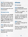
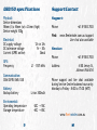
Contents
Introduction1
SIM card requirements
2
SIM card installation
3
OBD port connection
4
LED status6
SMS commands7
Optional: Live tracking
8
Troubleshooting9
Specifications
11
Support/Contact12
www.fleetminder.com.au
The fleetminder OBD150 is an inexpensive,
simple to install GPS tracking device
solution.
SIM card requirements
It can be fitted easily by the vehicle owner.
An active, full size, mobile phone type SIM
card is required for the OBD150 tracking
device to function.
The OBD150 GPS tracking device operates
via the vehicle’s OBDII computer diagnostic
port found on most passenger and light
commercial vehicles.
Live Tracking: Use the supplied Telstra
SIM card. Fleetminder will activate your
online tracking once the completed service
agreement is received and processed.
The benefits of connecting to the OBDII
port is that no wiring is required and the
tracking device can be hidden out of sight
- Plug & Go Tracking.
SMS Only: A SMS/voice prepaid or postpaid
plan is required. The SIM card supplied
can be used for Telstra plans, it is up to
you to activate this SIM card with a SMS/
voice plan of your choosing. If you would
like to use a different carrier (Vodafone,
Optus etc.), they will supply you with a
new SIM card.
The OBD150 is supplied with an OBDII
extension cable and a driver duress/panic
button.
Fleetminder take no responsibility for
excessive data charges.
For more information on SIM activation,
go to www.tinyurl.com/kmw8xow
SIM card installation
OBD port connection
Step 1) Using a flat bladed screw driver
gently prise both left and right sides
where the opening gaps are located. The
top cover can then be removed.
Step 1) Locate the OBDII computer
diagnostic port on your vehicle. It is usually
found under the dash. If you cannot find
it, consult your vehicle’s user manual.
Step 2) Insert the SIM card, as shown, and
push it firmly until it clears the bottom
cover edge, and as far it will go into the
SIM card socket.
Step 2) Optional: Extension cable.
Plug the OBD150 into the end of the
extension cable, and the extension cable
connector into the vehicle’s OBDII port.
Step 3) Replace the top cover.
The extension cable can used to better
hide the OBD150 tracker within the dash,
or to position for improved reception.
Step 3) Optional: Panic/Duress button.
Connect to the OBD150’s USB port and
mount button to a convenient place on
the dash.
For setting the phone number for duress,
see SMS Commands table on page 7. When
activated, the programmed mobile phone
number will receive a duress message and
GPS map location URL via SMS.
Step 4) Turn on the vehicle’s ignition to
provide power to the OBD150 tracking
device. Check the LED status on the
OBD150 device as described on page 6.
Step 5) Send a command via SMS to check
for correct operation.
SMS commands for testing:
PIN: Must send PIN command PIN 0000
(including space) to register your primary
mobile phone number to receive SMS
reports. To change the PIN to your own
4 digit PIN, send PIN 0000 followed by
NEWPIN xxxx (include spaces). Must be
sent as two separate messages.
STATUS: OBD150 will send a reply SMS
to your mobile phone showing enabled
features.
Step 6) Secure the extension cable and
the OBD150 as required within the dash.
Close any dash covers.
LED status
RED: Power indicator.
YELLOW: GSM/GPRS indicator.
ON: There is GSM connection to the mobile
network.
OFF: There is no connection - See
troubleshooting on page 9.
The indicator will flash during GPRS
connection to our the fleetminder server
(applicable only if the optional live
tracking has been activated).
GREEN: GPS indicator.
ON: The device is receiving signal from
the GPS satellites.
Please note, it may take up to 1 minute
for the device to receive signal after
powering on the device.
SMS commands
Note: Commands must be in CAPITALS
Command
Purpose/Report
PIN xxxx
Register primary mobile phone you are
sending commands from. If sending
commands from a different phone, you must
enter the PIN from that phone before SMS
reports can be received. Only the last phone
that sent the PIN command can receive
reports and control the device.
NEWPIN xxxx
Change the PIN to a 4 digit PIN of your
own. Original PIN must be entered first as a
separate command message
ie. PIN 0000 send NEWPIN 1234 send.
MAP
Will return the vehicle’s location with a map
URL link.
For smartphone users: open this link in your
browser to view the current location.
Other phones: URL link includes longitude
and latitude for manual entry.
(Include space. Default 0000)
(Include space)
SYS
Reports back additional parameters,
including device ID, firmware version,
voltage, GSM signal strength (%), GPS status
and GPRS status.
STATUS
Reports device ID, current vehicle speed
(km/h), backup battery power level (%), IP
address and port.
PH2 xxxxxxxxxx
Set emergency panic/duress phone
number. This phone number will receive an
emergency SMS alert if the driver engages
the panic button. This registered number
does not receive other reports or have
control over the device.
(Include space)
Live tracking
Great for business or personal use, live
web tracking has many more features than
SMS Only. With live tracking, the OBD150
sends location logs every 10 minutes, so
if a vehicle is stolen, it is possible to see
its last known location even if the OBD150
has been disabled or unplugged. 1 or 3
minute logs available (additional charges
apply).
Some other live tracking features:
Multi-device: Access via your web browser
on your PC/Mac, Smartphone or Tablet.
Replay a day: See were a vehicle has been
on any given day (6 months history).
Geo-fence setup: Set up a zone and be
alerted if the vehicle moves out of that
zone. Can also be used as tow/theft alert.
Multi-vehicle use: Track all of your
vehicles on the one account/login. Perfect
for businesses.
View reports: Vehicle activity, driving
time, mileage etc. (6 months history).
Troubleshooting
return the OBD150 to fleetminder for
testing.
PROBLEM: OBD150 device not sending
report data or not responding to
commands.
Red power LED on/Yellow LED off:
Check list in order of suggested steps:
SIM problem:
1) Did you send the command to the
correct SIM card number?
2) Is the SIM card plan still active? Or
has it expired. Check your invoices and
payments.
Hardware problem:
Access the OBDII port in the vehicle and
check the OBD150 unit.
Red power LED off:
Turn off the vehicle’s ignition and check
the OBDII wiring and extension cable if
used. Reconnect the OBD100 and extension
cable. If still not working, try the OBD150
in another vehicle. If still no power light,
This can mean that the SIM card is either
not active, not working or the vehicle is
in a 2G mobile “dead zone”. Drive the
vehicle to a known area with good mobile
reception. Wait 1 minute and check the
yellow LED again. If still no yellow light,
remove the OBD150 device from the
vehicle and remove and re-insert the SIM
card. Reconnect the OBD150 device. After
that, check SIM problem as per page 9.
Then test/replace the SIM card.
Red power LED on/Green LED off:
No signal from the GPS satellites. Drive
the vehicle to another location and check
again. Relocate the OBD150 to ensure
there is no metal above the device. If
still no green light, return the OBD150 to
fleetminder for testing.
OBD150 specifications
Support/Contact
Physical:
Device dimensions
58mm (l) x 45mm (w) x 23mm (high)
Device weight 100g
Support:
Electrical:
DC supply voltage DC tolerance voltage
Current (GPRS online)
GPS:
Frequency
12v or 24v
9v ~ 30v
36mA
L1 - 1575 MHz
Communication:
GSM/GPRS/SMS/USB
Battery:
Backup battery
Enviromental:
Operating temperature
Storage temperature
Li-ion 300mAh
-20C ~ +55C
-40C ~ +85C
Phone:
+61 8 9383 7833
Web: www.fleetminder.com.au/support
Live chat also available
Service:
Phone:
+61 8 9383 7833
Address:
4/50 Jersey St,
Jolimont WA 6014
Phone support and live chat available
during Service Centre business hours only:
Monday to Friday - 8:00 to 17:00 (WST)
www.fleetminder.com.au