1
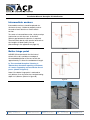
Installation Manual: Sentryline II Cable Barrier
Sentryline II Cable Barrier
Test Level 3 - 3 & Test Level 4 - 4 Cable Systems
Installation Manual
New South Wales
Sydney 02 9772 4172
Victoria
Melbourne 03 9213 5199
Queensland
Brisbane 07 3271 9133
Western Austalia
Perth
04 1743 0230
www.acprod.com.au
ACP | 28th January 2011 | Page
1
Installation Manual: Sentryline II Cable Barrier
Table of contents
Introduction
3
Safety statements
3
Before installation 4
Tension
4
Tools required 4
Intermediate anchors
5
Batter hinge point
5
Parts identification
6
Bill of materials
7
Installation instructions
8
Installation examples
15
Installation checklist
16
Appendix – technical drawings
Sentryline II Test Level 3 - 3 cable line post set up
18
Sentryline II Test Level 4 - 4 cable line post set up
18
Sentryline II WRBS Terminal End - Universal overlap
18
New South Wales
Sydney 02 9772 4172
Victoria
Melbourne 03 9213 5199
Queensland
Brisbane 07 3271 9133
Western Austalia
Perth
04 1743 0230
www.acprod.com.au
ACP | 28th January 2011 | Page
2
Installation Manual: Sentryline II Cable Barrier
Sentryline II Cable Barrier
System - Introduction
Safety statements
General safety
Test Level 3 – 3 Cable barrier
The Sentryline II TL-3 barrier is a 3 cable, high
tension cable barrier. The system has been
designed and tested to meet the evaluation
criteria of NCHRP 350 Test Level 3 (TL-3) for
a longitudinal barrier.
When correctly installed it is capable of
stopping, containing or redirecting an errant
vehicle in a safe manner under NCHRP 350
impact conditions. Those conditions are an
820kg passenger car and a 2,000kg pickup
truck impacting at 20 and 25 degrees at a
speed of 100kph.
» All required traffic safety precautions should
be complied with. All workers should wear
required safety clothing - high visibility vests,
steel capped footwear, gloves, hard hats,
safety glasses etc.
» Only authorised trained personnel should
operate any machinery. Where overhead
machinery is used, care must be taken to
avoid any overhead hazards.
» Before auguring, always have the area
checked for underground services by the
appropriate service providers.
» Gloves should be worn at all times.
Test Level 4 – 4 Cable barrier
The Sentryline II TL-4 barrier is a 4 cable, high
tension cable barrier. The system has been
designed and tested meet of the evaluation
criteria of NCHRP 350 Test Level 4 (TL-4) for
a longitudinal barrier.
When correctly installed it is capable of
stopping, containing or redirecting an errant
vehicle in a safe manner under NCHRP 350
impact conditions. Those conditions are an
820kg passenger car, 2,000kg pickup truck
and an 8,000kg truck impacting at 20, 25 and
15 degrees at a speed of 100kph and 80kph.
New South Wales
Sydney 02 9772 4172
Victoria
Melbourne 03 9213 5199
Sentryline II safety statements
» All installers must be well clear of machinery
while the holes are augured.
» The posts and components are easily lifted
and positioned by hand, while the cable and
reel are extremely heavy so it is recommended
that the cable is run out on a heavy duty,
single axis spindle.
» Avoid placing hands or fingers in and around
moving parts when components are being
lifted and manoeuvred into place.
» Only trained personnel should use the
tensioning machine. All installers must be
extremely careful they are clear of moving
parts when the hydraulic ram is being
operated.
Queensland
Brisbane 07 3271 9133
Western Austalia
Perth
04 1743 0230
www.acprod.com.au
ACP | 28th January 2011 | Page
3
Installation Manual: Sentryline II Cable Barrier
Before installation
Tension
Design, selection and placement of the
Sentryline II shall be in accordance with the
local road authority guidelines and the details
shown in the construction drawings. Installation
shall be in accordance with the installation
instructions supplied for this product.
It is important that when tensioning the
Sentryline II cable barrier that the tension
machine is set correctly. The tension machine
is usually set to 25kN’s (for 21-26°C days)
but may need to be changed to reflect the air
temperature at the time of installation as shown
in the table below. Advice should be sought on
all installations from your Sentryline II distributor.
Before installing a Sentryline II cable barrier,
ensure that all components required for the
system are on site and have been identified.
The Sentryline II is a highly engineered safety
device made up of relatively small number of
parts. Before starting installation ensure that
one is familiar with the make up of the system.
Refer to the ‘Bill of materials’ and ‘Parts
identification’ sections in this manual for more
information.
Depending on the application, post spacing
and circumstances at the site, installation and
assembly of the system should take a 2 person
crew less than 2 hours to cast the piles, install
the posts and place the cables for a 100m
section.
It is essential that the Sentryline II is installed
correctly. Please carefully read and understand
the following instructions before installing the
Sentryline II. These instructions relate only to the
installation of Sentryline II and are for standard
installations only.
Tension bays
Required at a minimum of every 450m or as
often as is necessary to correctly tension the
system. When installing the strong backs,
care must be taken to cut the cables mid span
between posts so that the installed strong
backs do not coincide with the line posts.
Note: Do not place two strong backs within
30m of each other when on the same cable.
Tools required
The tools required to install the Sentryline II
cable barrier are:
» Auger for drilling 300mm holes
» Machinery capable of lifting the cable reel
and a single axle spindle
» 300mm Wrench
» Measuring tape and marker pen
» String line
» Cut off saw
» Tensioning machine
Tension Table
Temp ºC (air)
0-3
4-9
10-14
15-20
21-26
26-32
33-37
38-43
Tension kN’s
32
30.5
28.5
26.5
25
23.2
21.5
19.5
New South Wales
Sydney 02 9772 4172
Victoria
Melbourne 03 9213 5199
Queensland
Brisbane 07 3271 9133
Western Austalia
Perth
04 1743 0230
www.acprod.com.au
ACP | 28th January 2011 | Page
4
Installation Manual: Sentryline II Cable Barrier
Intermediate anchors
Intermediate anchors should be placed at a
minimum of every 1,000m to properly anchor
the ends of each barrier run and maintain
tension.
To create an intermediate anchor, simply overlap
one barrier run with the next. A minimum
300mm gap between the barriers is required.
Terminate each barrier with terminal end so that
the Lengths of Need (LoN’s) line up.
(See drawing in the appendix on page 18)
Figure A
Batter hinge point
NCHRP 350 recommends that the lateral
extent of the soil, outside an envelope of
the embedded portion of the test article, be
approximately 1.3 times the embedment length.
ie: The standard Sentryline II footing is
750mm deep therefore requiring a minimum
of 1 metre supporting soil outside the line of
posts. (shown in figure A)
Note: If the batter hinge point is reduced to
only 600mm, then increase the standard footing
depth to 1,000mm. (Shown in figure B)
Figure B
New South Wales
Sydney 02 9772 4172
Victoria
Melbourne 03 9213 5199
Queensland
Brisbane 07 3271 9133
Western Austalia
Perth
04 1743 0230
www.acprod.com.au
ACP | 28th January 2011 | Page
5
Installation Manual: Sentryline II Cable Barrier
Sentryline II - Parts identification
» Line post & ‘O’ ring
» Cable grip
(required as per spacing specified)
(6 required per tension bay)
» Post cap
» Strong back
» Post socket
(1 required per post)
(3 required per tension bay)
(1 required per post)
» 3 Cable barrier
(3 x length of barrier required)
» 4 Cable barrier
(4x length of barrier required)
» Rebar ring
(1 required per post)
All steel components used in the Sentryline II are hot dipped galvanised, except the rebar ring
which are cast into the concrete piles.
New South Wales
Sydney 02 9772 4172
Victoria
Melbourne 03 9213 5199
Queensland
Brisbane 07 3271 9133
Western Austalia
Perth
04 1743 0230
www.acprod.com.au
ACP | 28th January 2011 | Page
6
Installation Manual: Sentryline II Cable Barrier
Sentryline II – Bill of materials
Components required for each post:
Cable Grips and associated components:
» 1 x Galvanised line post
(powder coating is optional)
» 1 x Plastic cap
» 1 x Plastic socket
» 1 x Rebar ring
» 1 x Rubber ‘o’ ring
TL3 - 3 Cable barrier
» 6 x Cable Grips c/w M20 nuts for each tension
bay
TL4 - 4 Cable barrier
» 8 x Cable grips c/w M20 nuts for each tension
bay
Cable required for both TL-3 and TL-4 systems:
TL-3 - 3 Cable barrier
» 3 x the total length of the barrier of 19mm
cable
Note: There may be more than 1 tension bay
per barrier run depending on the length or
design of the barrier.
Concrete required for each post:
» 1 x 0.053m³ 25 MPa concrete
TL-4 - 4 Cable barrier
» 4 x the total length of the barrier of 19mm
cable
Note: This is the theoretical volume only and
that allowance must be made that the holes
may be larger than this due to the act of drilling
and removing spoil.
Note: It pays to be conservative with these
lengths.
Strong Backs required for both TL-3 and TL-4
systems:
TL-3 - 3 Cable barrier
» 3 x Strong backs for each tension bay
TL-4 - 4 Cable barrier
» 4 x Strong backs for each tension bay
Note: There may be more than 1 tension bay
per barrier run depending on the length or
design of the barrier.
New South Wales
Sydney 02 9772 4172
Victoria
Melbourne 03 9213 5199
Queensland
Brisbane 07 3271 9133
Western Austalia
Perth
04 1743 0230
www.acprod.com.au
ACP | 28th January 2011 | Page
7
Installation Manual: Sentryline II Cable Barrier
Sentryline II
- Installation instructions
It is preferred that the Sentryline II is installed
on flat, level ground (minor site grading may
be required) with sufficient distance behind
the foundation piles as described in the ‘batter
hinge point’ section of this Installation Manual.
The Sentryline II barrier starts at post #5 (where
post #1 is the trigger post of the Sentryline
II WRBS Terminal End - Universal with post
spacing as described in the construction
drawings. (The first 4 line posts after the trigger
post are always at 2m spacing)
Before drilling always have the area checked
for underground services
Step 2 – Drilling the holes
Figure 1
‘Standard’ footing pile
Using an auger, drill 300mm diameter holes
750mm deep (shown in Figure 1 & 2) at the
spacing as shown in the construction drawings.
Theoretical volume of concrete required for each
pile is 0.053m³.
N.B. Due to the drilling and removing spoil, the
actual amount of concrete required is likely to
be larger than the theoretical volume.
NOTE: If the conditions on site don’t allow
for a 750mm hole it may be possible to use
a ‘shallow’ option. Soil tests will need to be
carried out and the required soil strength
present. For more details on this ‘shallow’
option and all other ‘alternative’ options
consult the ‘footings’ section under ‘design
considerations’ in the Sentryline II Product
Manual.
New South Wales
Sydney 02 9772 4172
Victoria
Melbourne 03 9213 5199
Figure 2
Queensland
Brisbane 07 3271 9133
Western Austalia
Perth
04 1743 0230
www.acprod.com.au
ACP | 28th January 2011 | Page
8
Installation Manual: Sentryline II Cable Barrier
Step 3 - Construction
Fill the holes to within 100mm of the top with
25mpa concrete, place the rebar ring in the
centre of the footing taking care to ensure that
the ring is centred in the hole and level. (shown
in figure 3) A string line and level are useful to
ensure this. Fill the remainder of the hole with
concrete until flush with grade.
(shown in figure 4)
New South Wales
Sydney 02 9772 4172
Push plastic socket into centre of the footing
until the top edge of the socket is flush with
the top of the concrete. (shown in figure 5)
Alignment of the socket is important so use of
a string line and level, or some other suitable
installation method, is required.
Note: To prevent the possibility of a socket
‘floating’ use a stiff mix of concrete or place a
post in the socket. (shown in figure 6)
Figure 3
Figure 5
Figure 4
Figure 6
Victoria
Melbourne 03 9213 5199
Queensland
Brisbane 07 3271 9133
Western Austalia
Perth
04 1743 0230
www.acprod.com.au
ACP | 28th January 2011 | Page
9
Installation Manual: Sentryline II Cable Barrier
Step 4 – Installing the posts
Push a rubber ‘o’ ring onto the bottom of the
post by approximately 350mm. This will prevent
debris from building up in the socket which can
make removal difficult. (shown in figure 7)
Slide a post into the socket once the concrete
has set and adjust the ‘o’ ring so that it fills the
gap between the post and post socket. (shown
in figure 8)
Ensure that the side slots in the post are aligned
so that the orientation of the two slots are
consistent. (shown in figure 9)
Figure 7
Figure 8
Figure 9
New South Wales
Sydney 02 9772 4172
Victoria
Melbourne 03 9213 5199
Queensland
Brisbane 07 3271 9133
Western Austalia
Perth
04 1743 0230
www.acprod.com.au
ACP | 28th January 2011 | Page 10
Installation Manual: Sentryline II Cable Barrier
Step 5 – Installing the cables
Using a truck or trailer fitted with a cable reel
frame, run the cables out to the desired length.
(shown in figure 10) One or more of the cables
may be run out at the same time depending on
the installer’s equipment. (shown in figure 11)
For a 3 cable system place the bottom 2 cables
into the bottom slots on either side of the post
and the top cable into the top slot. (shown in
figure 12)
For a 4 cable system place the bottom 2 cables
into the bottom slots on either side of the post
and the top 2 cables into the top slot.
Ensure that the cable is pushed fully down to
the bottom of the slots. (shown in figure 13)
New South Wales
Sydney 02 9772 4172
Figure 10
Figure 12
Figure 11
Figure 13
Victoria
Melbourne 03 9213 5199
Queensland
Brisbane 07 3271 9133
Western Austalia
Perth
04 1743 0230
www.acprod.com.au
ACP | 28th January 2011 | Page 11
Installation Manual: Sentryline II Cable Barrier
Step 6 – Placing the post caps
Slide the cap down the inside of the post and
push down until cap is pushed hard home onto
the top of the post. (shown in figure 14)
Note: Make sure that cap sleeves are on the
outside of the 2 cables in the bottom slots.
(shown in figure 15)
Step 7 – Connecting to the
cable barrier terminal end
Connect the cables to the terminal end as per
the manufacturer’s instructions. The Sentryline
II WRBS Terminal End - Universal is the
recommended terminal end for Sentryline II
cable barriers. (shown in figure 16)
Figure 14
Figure 16
Figure 15
New South Wales
Sydney 02 9772 4172
Victoria
Melbourne 03 9213 5199
Queensland
Brisbane 07 3271 9133
Western Austalia
Perth
04 1743 0230
www.acprod.com.au
ACP | 28th January 2011 | Page 12
Installation Manual: Sentryline II Cable Barrier
Step 8 – Connecting the cable
grips
At the desired location, cut the cable using a
cut off wheel in a grinder (treat cut end of cables
with a zinc containing paint). Mark the cable
with a marker pen 75mm from the cut end.
(shown in figure 17 & 18)
Now push the cable end into the cable grip
and ‘jiggle’ a few times until hard home and the
mark previously placed on the cable is flush
with the mouth of the fitting.
(shown in figure 19)
Note: If the cable has just been unwrapped and
still has an oily residue on it, wipe with a cloth
before fitting the cable grip.
It is acceptable for the cable to ease out of
the cable grip up to 10mm when tensioned.
If the cable has eased out more than 10mm,
remove the Cable Grip and refit. (shown in
figure 20)
Figure 17
Figure 19
Max 10mm
Figure 18
New South Wales
Sydney 02 9772 4172
Victoria
Melbourne 03 9213 5199
Figure 20
Queensland
Brisbane 07 3271 9133
Western Austalia
Perth
04 1743 0230
www.acprod.com.au
ACP | 28th January 2011 | Page 13
Installation Manual: Sentryline II Cable Barrier
Step 9 – Tensioning the barrier
Note: Tension is dependant on temperature,
therefore it may be necessary to adjust the
tension applied to suit the temperature. (refer to
the ‘System design’ section of the Sentryline II
Product Manual for more information)
Ensure full tension machine training,
including safe use, has been completed
before using the following methodology to
tension the cable barrier.
Tension machine and on site training is available
from Australian Construction Products Pty Ltd.
It is recommended that the supplied Sentryline II
tension machine is used.
Tensioning is achieved by pulling the cables
together using an appropriately placed strong
back and cable grip assembly.
Place the cable grips and strong back into
the tension machine ensuring that the cable is
held in place by the safety catches. Once all
personnel’s hands are clear, activate the tension
machine so that it contracts, pulling the cable
grips together and hence tensions the cables.
The tension machine is pre-set to stop at 25kN.
New South Wales
Sydney 02 9772 4172
Victoria
Melbourne 03 9213 5199
Run nuts up onto the threaded section of the
cable grips inside the strong backs by using a
ring spanner. (shown in insert below) Take care
not to place fingers between nut and turnbuckle
end.
Extend the tension machine so that the cable
grip and strong back are holding the cable
under tension. Remove the tension machine
and repeat until all cables have been tensioned
using the same technique.
Queensland
Brisbane 07 3271 9133
Western Austalia
Perth
04 1743 0230
www.acprod.com.au
ACP | 28th January 2011 | Page 14
Installation Manual: Sentryline II Cable Barrier
Sentryline II - Installation examples
» Sentryline II Test Level 3 – 3 Cable Barrier
» Sentryline II Test Level 4 – 4 Cable Barrier
New South Wales
Sydney 02 9772 4172
Victoria
Melbourne 03 9213 5199
Queensland
Brisbane 07 3271 9133
Western Austalia
Perth
04 1743 0230
www.acprod.com.au
ACP | 28th January 2011 | Page 15
Installation Manual: Sentryline II Cable Barrier
Appendix – Technical drawings
» 3 cables line post set up
» 4 cables line post set up
» Sentryline II WRBS Terminal End - Universal – Overlapping Sentryline II cable
New South Wales
Sydney 02 9772 4172
Victoria
Melbourne 03 9213 5199
Queensland
Brisbane 07 3271 9133
Western Austalia
Perth
04 1743 0230
www.acprod.com.au
ACP | 28th January 2011 | Page 16