1
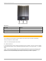
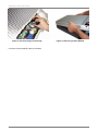
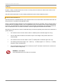
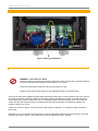
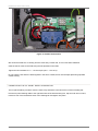
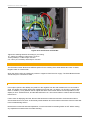
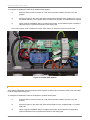
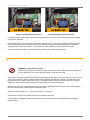
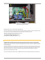
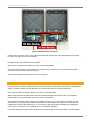
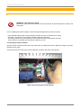
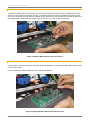
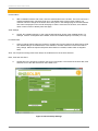
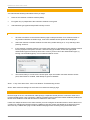
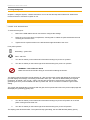
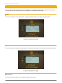
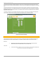
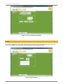
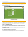
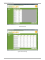
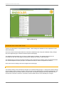
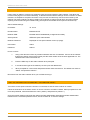
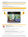
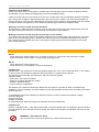
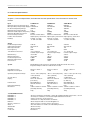
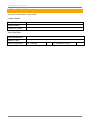
EnaSolar GT Series Solar Inverter
Installation Manual
Page 1
EnaSolar GT Series Solar Inverter
About EnaSolar
EnaSolar Limited (“EnaSolar”) is a division of Enatel Limited (“Enatel”), based in Christchurch, New Zealand.
EnaSolar designs, builds, and supplies efficient, cost effective, sustainable and upgradeable solar inverters to
the global market.
Trademarks
EnaSolar and the EnaSolar ‘e’ are both registered trademarks.
Notice of Copyright
Copyright © 2011 EnaSolar. No part of this document may be reproduced in any form or disclosed to third
parties without the express written consent of EnaSolar Ltd. 66 Treffers Road, Christchurch 8042, New Zealand.
EnaSolar reserves the right to revise this document and to periodically make changes to the content hereof
without obligation or organization of such revisions and changes, unless required to do so by prior arrangement.
Exclusion for Documentation
Unless specifically agreed to in writing, EnaSolar makes no warranty as to the accuracy, sufficiency, or
suitability of any technical or other information provided in its manuals or other documentation. EnaSolar
assumes no responsibility or liability for losses, damages, costs or expenses, whether special, direct, indirect,
consequential or incidental, which might arise out of the use of such information. The use of any such
information will be entirely at the user’s risk. Steps have been taken to maintain the accuracy of translation of
this manual into other languages other than English but there is no guarantee as to the correctness of such
translations.
Date/Version
May 2011 v1.4
Applicable for products
1.5kWGT-AUNZ/UK
2kWGT-AUNZ/UK
3kWGT-AUNZ/UK
1.5kWGT-AUNZE/UKE
2kWGTE-AUNZE/UKE
3kWGTE-AUNZE/UKE
Contact Information
Phone:
+64-3-366 4550
Fax:
+64-3-366 0884
Email:
[email protected]
Web:
www.enasolar.net
Installation Manual
Page 2
EnaSolar GT Series Solar Inverter
About This Manual
P U R P O S E A N D A U DI E NC E
The purpose of this installation manual is to explain the procedures for installing and troubleshooting the
EnaSolar GT Series Solar Inverter.
This manual is intended for qualified electrical installers. The Solar Inverter must only be installed by trained
specialists.
Please read the installation manual thoroughly before installing the device and keep it safe for future reference.
SYMBOLS USED
Throughout the installation manual we use certain symbols. Here is what they mean:
WARNING
Warnings identify conditions that could result in personal injury or loss of life.
CAUTION
Cautions identify conditions or practices that could result in damage to the unit or other
equipment.
IM PORTAN T NOTICE TO THE INSTALLER
This manual must remain in the possession of the end user customer.
Once the installation has been completed the relevant data must be
filled in the rear section of this manual. This data may be used for the
customers’ reference and to aid in any technical assistance.
WARRANTY R EGISTRATION
To validate the warranty for a newly installed inverter, the registration
must be carried out within 1 week of installation.
This form is to be filled out either on the EnaSolar website at:
www.enasolar.net/warranty
Or on the EnaSolar reporting software platform “Online” at:
http://partner.enasolar.net
Installation Manual
Page 3
EnaSolar GT Series Solar Inverter
Contents
About This Manual ............................................................................................................................................... 3
Purpose and Audience ................................................................................................................................... 3
Symbols Used ................................................................................................................................................ 3
Important Notice to the Installer...................................................................................................................... 3
Warranty Registration..................................................................................................................................... 3
Safety Instructions ............................................................................................................................................... 6
1. Introduction ...................................................................................................................................................... 7
About the EnaSolar GT Series Solar Inverter ................................................................................................. 7
Unit Description .............................................................................................................................................. 7
Understanding the Part Number ..................................................................................................................... 8
Unpacking the Inverter ................................................................................................................................... 9
2. Installation...................................................................................................................................................... 11
Installation Options ....................................................................................................................................... 11
Before You Begin ......................................................................................................................................... 11
Preparation .................................................................................................................................................. 12
Location Requirements ................................................................................................................................ 12
Wi-Fi Networking Requirements ................................................................................................................... 13
Installing the Wall mounting box ................................................................................................................... 13
3. Wiring ............................................................................................................................................................ 15
Wiring Compartment .................................................................................................................................... 16
Earthing of Solar Modules ............................................................................................................................ 18
Additional Wall Mount Box Information ......................................................................................................... 22
Inverter Module ............................................................................................................................................ 23
4. Configuration ................................................................................................................................................. 26
Network Setup.............................................................................................................................................. 26
Installing the Installer Utility .......................................................................................................................... 26
Information Reporting ................................................................................................................................... 27
Using the Solar Installation Utility ................................................................................................................. 27
General ........................................................................................................................................................ 28
Wireless Network Setup ............................................................................................................................... 29
Ethernet Network Setup ............................................................................................................................... 29
Test the customers Webpage....................................................................................................................... 30
5. Using the System ........................................................................................................................................... 32
Commissioning the System .......................................................................................................................... 32
Stopping the System .................................................................................................................................... 32
Navigating the front panel ............................................................................................................................ 33
6. Advanced Settings ......................................................................................................................................... 35
Advanced Network Setup ............................................................................................................................. 35
Grid connect Settings ................................................................................................................................... 35
Time and date .............................................................................................................................................. 36
Other ............................................................................................................................................................ 37
Information ................................................................................................................................................... 38
Logs ............................................................................................................................................................. 38
Inverter Settings Web Page.......................................................................................................................... 40
Adhoc network ............................................................................................................................................. 43
Lost or Forgotten Password / Password Reset ............................................................................................. 43
7. Troubleshooting ............................................................................................................................................. 44
Installer Serviceable components ................................................................................................................. 44
Network Troubleshooting ............................................................................................................................. 45
General Troubleshooting .............................................................................................................................. 46
8. Maintenance .................................................................................................................................................. 47
Routine Maintenance Tasks ......................................................................................................................... 47
Installation Manual
Page 4
EnaSolar GT Series Solar Inverter
9. Technical Specification .................................................................................................................................. 48
Warranty ............................................................................................................................................................ 49
Warranty Registration ........................................................................................................................................ 49
Glossary ............................................................................................................................................................ 49
Installation Data ........................................................................................................................................... 50
Table of Figures
Figure 1 Installed Inverter .................................................................................................................................... 8 Figure 2 Unscrewing Display Module .................................................................................................................. 9 Figure 3 Lifting Display Module ............................................................................................................................ 9
Figure 4 Removing Connectors ........................................................................................................................... 9 Figure 5 Disconnecting Inverter Plugs .............................................................................................................. 10 Figure 6 Removing Inverter Module .................................................................................................................. 10
Figure 7 Inverter Parts ....................................................................................................................................... 11 Figure 8 Wall Mounting Box ............................................................................................................................... 13 Figure 9 Wall Mounting Box Fixed to the Wall.................................................................................................... 14 Figure 10 Wiring Compartment .......................................................................................................................... 16 Figure 11 PV Wire Connections ......................................................................................................................... 17 Figure 12 PV Connection to Earth Bar ............................................................................................................... 18 Figure 13 Isolated Earth System ........................................................................................................................ 19 Figure 14 Positive Earth Connection .................................................................................................................. 20 Figure 15 Negative Earth Connection ................................................................................................................ 20
Figure 16 AC wiring connections ....................................................................................................................... 21 Figure 17 Multiple Unit Connections .................................................................................................................. 22 Figure 18 Connecting the Inverter Module ......................................................................................................... 23 Figure 19 Display Module (Wi-Fi) with Connections ........................................................................................... 24 Figure 20 Display Module (Ethernet) with Connections ...................................................................................... 24 Figure 21 General Setup Settings ...................................................................................................................... 28 Figure 22 Wireless Network Setup Settings ....................................................................................................... 30 Figure 23 Customer’s Internal Webpage ............................................................................................................ 31 Figure 24 Display Home page............................................................................................................................ 33 Figure 25 Display Totals page ........................................................................................................................... 33 Figure 26 Display Voltages page ....................................................................................................................... 34 Figure 27 Display Network page ........................................................................................................................ 34 Figure 28 Advanced Network Settings ............................................................................................................... 35 Figure 29 Grid Connect Settings ........................................................................................................................ 36 Figure 30 Time and Date Setup Settings ........................................................................................................... 37 Figure 31 Other Settings .................................................................................................................................... 37 Figure 32 Inverter Information ............................................................................................................................ 38 Figure 33 Daily log ............................................................................................................................................. 39 Figure 34 Five minute log .................................................................................................................................. 39 Figure 35 Event log ............................................................................................................................................ 40 Figure 36 Wireless Settings -Webpage .............................................................................................................. 41 Figure 37 Network Settings -Webpage .............................................................................................................. 41 Figure 38 Time & Date Settings -Webpage ........................................................................................................ 42 Figure 39 Versions -Webpage ........................................................................................................................... 42 Figure 40 Installer Serviceable Components...................................................................................................... 44 Installation Manual
Page 5
EnaSolar GT Series Solar Inverter
Safety Instructions
This manual contains important safety and operating instructions. Keep it safe for future reference.
Before installing and using the inverter module, read all the instructions carefully.
WARNING
The following warnings identify practices that could result in personal injury or death.
When the device is in use it can become quite hot (up to 70° C in normal operation, depending on the ambient
temperature). Do not touch the inverter while it is being operated or you may get burned.
Do not cover or obstruct the inverter, because it could overheat and become a fire hazard.
Make sure that the wiring is kept in good condition and is the correct size and type for its purpose.
Unless you are a qualified electrician, you must not open the inverter or attempt any type of repair or
modification to the wiring. There may still be a high residual voltage within the inverter itself even if you have
switched off the power source.
Never attempt to remove, repair or modify the inverter until the AC and DC power has been disconnected.
CAUTION
The following cautions identify conditions or practices that could result in damage to the
unit or other equipment.
When installing the inverter make sure you follow the recommended clearances and location instructions. Do
not install it in a location that does not have ventilation as this could lead to overheating and damage to the unit
or significantly reduce its life or reduce power output.
Do not open the display module or the inverter module. They contain no user-serviceable parts.
Installation Manual
Page 6
EnaSolar GT Series Solar Inverter
1. Introduction
Chapter 1, Introduction, describes the features and functions of the EnaSolar GT Series Solar Inverter.
A B O UT T HE E NA S OL A R G T S E R I E S S O L A R I NV E R TE R
The EnaSolar GT Series Solar Inverter is designed to convert solar energy to AC (mains) power, which can be
used to power appliances in a home or business.
The EnaSolar GT Series Solar Inverter features:
•
DC and AC isolating switches
•
low operating voltage range, starting at 120V allowing you to install with a minimal panel array
•
light weight inverter – 15kg in the 3kW unit
•
built in Wi-Fi and stats package as standard, optional Ethernet version available
•
5 year warranty
•
easy upgrade path to larger units, changing only the main module and re-using the back mount,
control panel and all wiring.
•
front mounted heat sink allows more airflow, easy care and cleaning
•
an efficient design
U NI T D E S C R I P T I O N
The EnaSolar GT Series Solar Inverter are made up of several components:
•
a wall mounting box containing the wiring compartment
•
a removable display module containing an LCD panel and Wi-Fi (Optional Ethernet)
•
a removable inverter module containing the power electronics and heat sink
•
a wireless antenna (not included with Ethernet version)
Installation Manual
Page 7
EnaSolar GT Series Solar Inverter
Figure 1 Installed Inverter
Dimensions
Case width
330mm
Case height (including switch handles)
550mm
Case depth
140mm
Total weight
15kg (for the 3kWGT unit)
U N D E R S T A N DI N G T H E P A R T N U MB E R
The Part Number of the EnaSolar GT Series Inverters can be broken down to for better understanding.
Taking for example the 1.5kWGT-AUNZE
1.5kW - the nominal output power of the inverter
GT - stands for Grid Tied
E - This identifies that the inverter is fitted with the Ethernet version of display. There are 2x versions of display
interface: Ethernet and Wi-Fi. Wi-Fi is standard and if fitted there will be no E in the part number. I.e. 1.5kWGTAUNZ
-AUNZ – This is the country identifier which has the specific parameters for the grid connect settings for that
country. AUNZ (Australia/New Zealand) uses the same settings as they are both governed by the AS4777
regulations. For the -UK (United Kingdom) the settings are governed by the G83/1-1 regulations.
Installation Manual
Page 8
EnaSolar GT Series Solar Inverter
U N P A CK I N G T H E I NV E R TE R
The GT Series Inverters comes partially assembled out of the box. This reduces the weight and cost of
packaging/shipping. The packaging materials are recyclable to help reduce the materials going to landfill.
After removing the inverter from the box, undo the 4x screws, slide hands under the Inverter Module and lift to
assist in removal of the Display Module.
Figure 2 Unscrewing Display Module
Figure 3 Lifting Display Module
Then carefully disconnect the 3x cables from the display PCB (ground tab, communications cable, Wi-Fi coaxial
connector). Note: When removing the coaxial connector do not pull on the cable. The Wi-Fi connector is not
fitted for the Ethernet version.
Figure 4 Removing Connectors
Set the Display Module aside.
Disconnect the 2x main inverter connectors by squeezing the side release tabs and carefully pulling out.
Installation Manual
Page 9
EnaSolar GT Series Solar Inverter
Figure 5 Disconnecting Inverter Plugs
Figure 6 Removing Inverter Module
Lift off the Inverter Module and then set aside
Installation Manual
Page 10
EnaSolar GT Series Solar Inverter
2. Installation
Chapter 2, Installation, contains information about how and where to install the EnaSolar GT Series Solar
Inverter.
I NS TA L L A TI O N O P T I O NS
The EnaSolar GT Series Solar Inverter can be installed as a single inverter connected to a single PV array, or
multiple PV arrays.
Multiple EnaSolar GT Series Solar Inverters can be installed side by side.
The EnaSolar GT Series Solar Inverter can be connected to a home network using Wi-Fi if one is available.
B E F O R E Y O U B E GI N
Unpack the box containing the EnaSolar GT Series Solar Inverter and make sure that you have all the required
parts.
Figure 7 Inverter Parts
Installation Manual
Page 11
EnaSolar GT Series Solar Inverter
1)
Wall mounting case x1
4)
Antenna
x1
2)
Display module
x1
5)
Conduit bungs
x2
3)
Inverter module
x1
6)
Mounting Hardware
x6
Note: If installing an Ethernet version display module (identified by an ‘E’ in the part number) there will be no
antenna included.
Eliminate the chance of dissimilar metal corrosion by using the supplied mounting hardware.
If you are missing any of the inverter parts that you need for the installation, please contact your EnaSolar
representative.
P RE P A RA TI O N
Obtain the required network settings from the site owner (see the Network Setup section for further information).
Check that the panel configuration (voltage and current) is suitable for the inverter.
Have the latest version of Installation software loaded onto the notebook/PC that will be used to configure the
inverter. Requires a minimum OS of windows XP or later. A USB to mini USB cable is required to connect from
the notebook/PC to the inverter display module.
L OC A TI O N RE Q UI RE ME NT S
The EnaSolar GT Series Solar Inverter can be installed indoors or outdoors. It must be installed somewhere
with a free flow of air, where the ambient temperature is between -25°c and +50°c. It must be installed in a
location that is out of direct sunlight during peak power times when the sun is at its hottest, as the sun’s heat
may interfere with the cooling abilities of the inverter module.
Our standard warranty terms can be found on our website. However the warranty may be compromised if the
inverter is not installed in strict accordance with the installation guidelines contained in this installation manual.
The minimum requirements for airflow around the heat sink are a major factor contributing to efficient cooling of
the inverter and as a result the inverter should never be installed where these minimum space requirements are
not met.
The inverter must be mounted vertically, with the wiring box at the bottom, on a wall or other flat surface, with at
least 100cm clearance between the bottom of the unit and the ground, at least 40cm clearance between the top
of the unit and any other surface and 7cm between any surface and the side of the inverter.
Do not mount inverters above each other or another source of hot air.
Do not install the inverter anywhere that it is likely to accumulate debris such as tree leaves or large amounts of
dust.
Do not mount the inverter in a cupboard or an enclosed space. This may cause the inverter to overheat and
potentially cause damage.
Installation Manual
Page 12
EnaSolar GT Series Solar Inverter
S U R FA CE S FO R I N S T A L L A TIO N
The wall mounting box can be attached to a vertical surface such as plaster board, wood siding, concrete wall,
or pole assembly. Make sure the mounting surface is flat and can support the weight of the inverter (14kg)
before you begin. If you are installing onto plaster board, use supporting material such as plywood or secure the
fasteners to supporting wall studs. The inverter must not be installed directly on galvanised steel, for corrosion
reasons.
W I - FI N E T WO RK I NG RE Q UI RE M E N TS
In order to make use of the wireless capabilities of the inverter unit, the homeowner must provide wireless
networking capabilities. The wireless router must be located close enough to the inverter to have a minimum of
30% signal strength at the inverter location to maintain connection. (See the section on Wi-Fi range
considerations on page 22 for more info)
The network security settings need to be known. The inverter is compatible with both WPA and WEP.
A list of known compatible wireless routers is available on the dealers section of the EnaSolar website.
I NS TA L L I N G TH E WA L L MO UN TI NG BO X
The metal wall mounting box comes with six pre-drilled 8mm screw holes for attaching it to the wall, as well as
eight conduit holes for the electrical cables.
Figure 8 Wall Mounting Box
Installation Manual
Page 13
EnaSolar GT Series Solar Inverter
S UG G E S TE D I N S TA L LA T I O N M E T HO D
1.
Using the wall mounting box as a template, mark the required screw locations.
2.
Set aside the wall mounting box and drill the marked screw hole locations. A minimum of four
screws are required to fix the wall mounting box to the wall.
3.
Using the supplied mounting hardware, fit the wall mounting box and insert screws through the
drilled holes so that the box is held firmly in place. Ensure that you use the supplied fasteners that
are capable of holding the unit securely.
4.
Inspect the installation for any potential water leaks. Seal using an appropriate silicone sealant.
Note: If the inverter is incorrectly installed, this will void the warranty. Please see our warranty terms and
conditions on our website.
Figure 9 Wall Mounting Box Fixed to the Wall
Installation Manual
Page 14
EnaSolar GT Series Solar Inverter
3. Wiring
Chapter 3, Wiring, contains instructions on how to correctly wire the EnaSolar GT Series Solar Inverter to the
solar array and to the AC power.
Only solar trained electricians or other suitably qualified technicians should install this product.
WI RI NG REQ UI R E ME N TS
Wire sizes must be coordinated with the array maximum short circuit current and the AC breaker sizes used. All
wiring must be in accordance with applicable codes.
Wiring in Australia and New Zealand must meet AS/NZS3100 and AS4777 standards. AS4777 requires that the
inverter feeds into a separate breaker on the AC distribution board. This breaker must be rated for bidirectional
power flow. This standard also requires that specific signs and labels are attached to the distribution board and
main AC distribution board. For further information consult the appropriate standards documentation.
Wire size for the AC and DC is critical. Undersized wiring can lead to significant power losses and a reduction in
system efficiency.
•
The maximum size for the DC cable is 16mm2 or 6AWG (solid or stranded copper wire only).
•
The DC cable must be rated for the maximum open circuit voltage of the panels. 600V min is
recommended.
•
The maximum size for the AC cables is 16mm2 or 6AWG (solid or stranded copper wire only).
•
The earthing terminal wire range is 2.5 – 25mm2 (4 – 14 AWG) copper or 4 – 25mm2 (4 – 12 AWG)
aluminium solid or stranded wire.
•
We recommend that the DC wires are a minimum of 4mm2 and that the AC wires are a minimum of
2.5mm2 to reduce voltage drop.
WARNING – Fire Hazard
Using undersized wiring can result in a fire hazard.
Installation Manual
Page 15
EnaSolar GT Series Solar Inverter
WI RI NG CO MP A R TME NT
Figure 10 Wiring Compartment
C O N N E C T I NG T H E D C WI RI N G
WARNING – Risk of Electric Shock
Before you begin connecting the electrical components, make sure that the AC and DC switches
are both in the Off position and the inverter module is not in place.
Ensure the incoming DC cables are disconnected at the PV cells.
Ensure the AC Inverter feed breaker on the distribution board is in the Off position.
There are 2x empty bung positions at either side of the wall mounting box to route conduit for wire entry. Ensure
all unused conduit entry points are fitted with the spare conduit bungs that are supplied. If required these may
be transposed to a desired conduit entry hole. Fix a suitable length of electrical conduit to the case. Feed the
cables from the solar array through this conduit and into the wall mounting box, identifying the positive and
negative cables as you do so.
If there are 2 arrays of panels, ensure that both of the strings are identical, i.e. the same number of panels in
each string.
Strip 9mm (⅜ inch) of insulation from the wire(s). Insert the appropriate cables into the DC terminals. There are
two terminals for PV+ and PV-, which allow you to wire two strings of panels in parallel.
Installation Manual
Page 16
EnaSolar GT Series Solar Inverter
Figure 11 PV Wire Connections
We recommend that the +ve wire(s) from the solar array is either red, or has a red sleeve attached.
Cable tie the DC wires to the PCB using the slot provided on the PBC.
Tighten the DC terminals to 1.2 – 1.5 Nm torque (10.6 – 13.3 Lb-In).
Do not route the AC and DC cables together in the same conduit, these must be kept apart using separate
conduit routing.
CONNECTING THE PV PANEL EARTH CONDUCTOR
The PV panel earthing conductor from the solar array should be connected to the inverter’s earthing bar.
Pull the PV panel earthing cable to the right-hand side of the wall mounting box, strip the end 10mm of wire,
insert into one of the termination holes of the earthing bar and tighten into place.
Installation Manual
Page 17
EnaSolar GT Series Solar Inverter
Figure 12 PV Connection to Earth Bar
Tighten the earthing terminals according to your wiring:
16 – 25mm (4–6 AWG) / 5 Nm torque / 45 Lb-In
10mm (8 AWG) / 4.5 Nm torque / 40 Lb-In
2.5 – 6mm (10–14 AWG) / 8 Nm torque / 35 Lb-In
EARTHING OF SOLAR MODULES
The EnaSolar inverter allows three different options for the earthing of the Solar Module DC Poles: Isolated,
Negative earth or Positive earth.
Note: this section refers to earthing the positive or negative of the Solar DC supply. The Solar Module frames
should always be connected to earth.
I S O LA TE D E A RT H S Y S T E M
In this option (which is the default), the positive or the negative from the solar modules are not connected to
earth. On startup, the inverter will test the impedance from both the +ve and the –ve DC input, to ensure that
there is > 600kΩ (+-15%) between the DC inputs and earth. If the inverter detects a lower impedance, it will
display an error “PV Earth Fault”, and the RED LED will be on. The inverter will then continue with the startup
tests and run.
If the inverter is displaying this fault, then the fault should be located and resolved. If left unresolved and a
second earth fault occurs, then an electrically unsafe situation and a fire hazard could result. See PV earth fault
in the troubleshooting section.
Note that the inverter has internal impedances, so ensure that the DC Isolating Switch is OFF before making
any impedance measurements for trouble shooting.
Installation Manual
Page 18
EnaSolar GT Series Solar Inverter
To configure the EnaSolar inverter as an Isolated Earth System:
1)
Ensure that the inverter is turned off – both the DC and AC isolators must be in the “Off”
position.
2)
Move the jumper on the end of the yellow/orange wire and place on the “Isolated” tab. This is
the default selection, so the jumper does not need to be moved if an isolated earth is required.
3)
When using the installation utility to configure the inverter, ensure that the option “Isolated” is
selected on the PV panel earth section of the Setup page.
Note: If the inverter earth is selected as “None” there will be no monitoring of the PV panel earth.
Figure 13 Isolated Earth System
N E G A TI VE O R P O SI TI VE E A RT H SYS TE M
Some panels (particularly thin film) require that the negative or positive be connected to earth. This connection
is via the large “Earth Fault” fuse.
To configure the EnaSolar inverter as a negative or positive earth system:
1)
Ensure that the inverter is turned off – both the DC and AC isolators must be in the “Off”
position.
2)
Move the jumper on the end of the yellow wire and place on the “negative earth” or “positive
earth” tab.
3)
When using the installation utility to configure the inverter, ensure that the corresponding
option is selected on the PV panel earth section of the Setup page.
Installation Manual
Page 19
EnaSolar GT Series Solar Inverter
Figure 14 Positive Earth Connection
Figure 15 Negative Earth Connection
For safety reasons ensure that all earth reference tabs that are not in use have a terminating jumper installed
over the bare terminals.
If an earth fault occurs on the panels that results in a greater than 1A of PV current flowing to earth, the Earth
Fault Fuse will blow, disconnecting the fault current path.The inverter will detect the blown fuse, will display
“Earth Fuse Fail”, and will shut down, as an electrically unsafe situation and a fire hazard could exist.
If the Earth Fault fuse is blown, see the PV Earth Fuse fail in the troubleshooting section.
C O NN E C T I N G T H E A C W I R I N G
WARNING – Risk of Electric Shock
Make sure the DC and AC switches on the inverter unit are set to Off, and the breaker switch in
the AC distribution is set to Off, before you begin connecting the wiring.
There are 2x empty bung positions at either side of the wall mounting box to route conduit for wire entry. Ensure
all unused conduit entry points are fitted with the spare conduit bungs that are supplied. If required these may
be transposed to a desired conduit entry hole. Fix a suitable length of electrical conduit to the case. Feed the
cables from the AC power supply through this conduit and into the wall mounting box.
Strip 9mm (⅜ inch) of insulation from the wires. Connect the phase and neutral from the mains power cable to
the AC terminals on the right-hand side of the wiring panel.
Tighten the AC terminals to 1.2 – 1.5 Nm torque (10.6 – 13.3 Lb-In).
Cable tie the AC wires to the PCB using the slot provided on the PCB.
Do not route the AC and DC cables together in the same conduit, these must be kept apart using separate
conduit routing.
Installation Manual
Page 20
EnaSolar GT Series Solar Inverter
Figure 16 AC wiring connections
CONNECTING THE AC EARTHING CONNECTOR
Pull the AC earthing wire to the right-hand side of the wall mounting box. Remove 10mm of insulation from the
wire. Insert into one of the termination holes of the earthing bar and tighten into place.
Tighten the earthing terminals according to your wiring:
16 – 25mm (4–6 AWG) / 5 Nm torque / 45 Lb-In
10mm (8 AWG) / 4.5 Nm torque / 40 Lb-In
2.5 – 6mm (10–14 AWG) / 8 Nm torque / 35 Lb-In
C O NN E CT I NG M U L TI P L E U NI T S
If multiple inverters are being used each inverter unit must be wired to its own PV array. You can position
multiple inverter units side by side on the wall. Please note that you must not connect the same panels into
more than one inverter. For the AC connection we suggest that each inverter be wired to a different AC phase
for phase balancing.
Second or subsequent PV array cables can be fed through the first inverter unit (thread the cable through the
upper left-hand conduit hole, through the first inverter unit, out through the upper right-hand conduit hole and
into the second inverter unit). This lets you keep the wiring tidy while still having separate connections.
Earth each inverter through its AC cable.
If you are connecting more than one unit, complete the wiring for each unit before moving on to the next one.
Installation Manual
Page 21
EnaSolar GT Series Solar Inverter
Figure 17 Multiple Unit Connections
If there will be more than one PV array, label the positive and negative wire pairs appropriately (for example,
PV1 POS, PV1 NEG, PV2 POS, PV2 NEG).
CONNECTING THE WIRELESS ANTENNA
Note: This is not applicable for Ethernet version of the Display Module
The Solar Inverter is able to communicate with a network using a wireless link. The wireless coaxial cable
comes pre-connected to the wall mounting box.
Screw in the antenna to the bottom of the wall mounting box.
ADDITIONAL WALL MOUNT BOX INFORMATION
If fitting an Ethernet version of Display Module ensure to route the communication cable (cat5 or cat6 Ethernet
cable) in separate conduit to ensure that there is no noise induced into the communications line.
Ensure that all cables are outdoor rated if the inverter is mounted outside.
When routing the Ethernet cable ensure that there is sufficient length to be able to connect to the display
module when it is being suspended, to allow for ease of configuration.
The EnaSolar GT Series Solar Inverter can be installed in stages. You have the option of installing the wall
mounting box, wiring and inverter module at separate times or all together at the same time. If you are not
installing the inverter module at this point, you can make the wall mounting box waterproof by installing the
service panel. The service cover is available from your EnaSolar distributor.
If you are installing the inverter module at this point you should continue to the next section, “Inverter Module.”
Installation Manual
Page 22
EnaSolar GT Series Solar Inverter
I NV E R T E R M OD U LE
C O N N E C T I NG T H E I N V E R T E R M O DU LE
WARNING – Risk of Electric Shock
Before connecting the inverter module, make sure that the AC and DC switches are both in the
Off position
Prior to installing the inverter module, ensure that the following items have been checked:
- Every possible ingress point of water and dust is sealed correctly to maintain the IP rating.
- There are no loose items, wire strands or debris inside the wiring area.
- The fixing hardware is not over-torqued to ensure that the inverter housing does not warp.
If the inverter is not installed correctly then the warranty is void.
Connecting the inverter module:
Slot the inverter module into place at the top of the wall unit, making sure that no cables are caught or pinched
between the two units.
Connect the 6-pin and 9-pin plugs to their respective sockets in the wiring compartment.
Figure 18 Connecting the Inverter Module
Installation Manual
Page 23
EnaSolar GT Series Solar Inverter
A T TA C H T HE DI S P L A Y M O D ULE ( WI - FI )
To attach the display panel to the inverter unit, connect the earthing wire from the back of display panel to the
earth bar in the wiring box and fasten securely. The display panel can then be suspended from this wire while
you work. Connect the four-pin lead to the display board. Connect the coaxial cable from the wireless antenna to
the display board. Leave the display module open so that you can continue with configuration.
Figure 19 Display Module (Wi-Fi) with Connections
A T TA C H T HE DI S P L A Y M O D ULE ( E TH E R N E T )
As per the above Wi-Fi version attach the Ethernet Display Module by connecting the Earth cable and the 4 way
communication cable.
Connect the Ethernet cable to Ethernet port on the Display Module.
Figure 20 Display Module (Ethernet) with Connections
Installation Manual
Page 24
EnaSolar GT Series Solar Inverter
TESTING THE DC AND AC VOLTAGE
1.
Switch off and lock DC and AC inverter switches.
2.
Check that the solar array plugs are correctly installed.
3.
Re-connect the solar array and expose it to full sunlight which is intense enough to produce the
required output voltage.
4.
Measure the PV array open circuit DC voltage across the DC positive (+) and negative (-) terminals
in the wall mounting box. This voltage must be greater than 150 volts DC and less than 600 volts
DC.
5.
Turn on the breaker at the AC distribution.
6.
Using an AC voltmeter, measure the AC open circuit voltage, and make sure that the voltage is at
approximately the nominal value.
7.
Turn on the DC isolator and measure the DC voltage at the terminals, this should not have changed.
Potential damage to inverter
The open circuit DC voltage must be less than 600 volts DC at all times, to prevent damage to
the inverter.
Installation Manual
Page 25
EnaSolar GT Series Solar Inverter
4. Configuration
Chapter 4, Configuration, contains instructions on how to configure the EnaSolar GT Series Solar Inverter for
use.
Note: The DC isolation switch on the inverter distribution must be turned on at this point.
The inverter will require to be configured to:
-Set the Network (Wi-Fi/Ethernet) settings
-Change any grid access settings from the default
-Set the panel earth setting
Configure the inverter as required following the instructions in the Configuration section.
N E T W OR K S E T U P
W I - FI R A N G E CO NS I DE RA T I O N S
Before you begin configuration you should establish whether the homeowner’s wireless network is within range.
A laptop, PDA or mobile phone with Wi-Fi can be used at the proposed site of Installation to test the signal
strength. The inverter should be installed as close as possible to the user’s access point. Ideally the signal
strength will be at least 30% for reliable operation.
The range of wireless networks varies depending on the installation due to obstacles, reflections, and
interference. The typical maximum range between the inverter and the access point (when going through walls)
is 20m.
Any obstacle in the signal path between the inverter and access point will decrease the radio signal. High
humidity and moisture on walls will absorb the radio signal and decrease the range. Walls with metal in them
and concrete walls will decrease the signal strength significantly.
The aerials on the inverter and the access point should always be vertical. These aerials should also be
mounted above ground and away from metal objects. Larger directional antennas can be used on the access
point, inverter or both, if an increase in signal strength between them is required. Installing a directional antenna
may not always increase the signal strength as there are many variables that influence the range.
Wi-Fi range is also affected by interference from other devices such as microwave ovens, 2.4GHz cordless
phones, Bluetooth devices, and other Wi-Fi devices. If there is another Wi-Fi access point within range of the
user’s access point, the access point can be configured to operate on a different channel. For example, if a
neighbouring access point is on channel 6 then configure the user’s access point to channel 1 or 11.
I NS TA L L I N G TH E I NS TA L L E R UTI LI T Y
The inverter requires software which you must use to configure its settings when installing a new inverter. This
software is available from the Partners section of the EnaSolar website. This should be installed on a PC
running Windows XP or later and with an available USB port. A laptop with built-in Wi-Fi is preferred.
Installation Manual
Page 26
EnaSolar GT Series Solar Inverter
Ensure that you have the latest version of installation utility installed on the PC prior to installing the inverter. All
required software and supporting material is available from the EnaSolar website.
Once the software has been downloaded, follow the prompts on the installation utility to install the installation
utility. Open the utility. At this stage the USB driver will install automatically.
I NF O R MA TI O N R E P O R T I NG
If an inverter is connected to a wireless access point, data from the 5 minute and event logs will be collated and
sent on the hour to EnaSolar servers in order to provide detailed performance data for the EnaSolar reporting
software.
This information is read-only from the servers and will have no security concerns for the customer. The data that
is pushed from the inverter contains no site or personal information.
There will be a limited amount of bandwidth use to push this data to the servers (approximately 1Mb of data per
month).
This feature may be disabled by selecting a check box in the Advanced Settings of the Installation Utility. By
doing this there will be no information about the inverter’s performance sent to EnaSolar and therefore, they will
not be able to monitor if there are any anomalies with the installation.
U S I NG T H E S O L A R I NS T A L L A T I O N U TI LI TY
To configure a new inverter, connect the PC to the inverter using a USB to mini USB cable. The mini USB port
is on the back of the display panel.
Start the EnaSolar Installer Utility.
If an inverter is not connected to the PC then the utility will display an error message. If this happens, plug the
inverter in to the PC and click the scan button at the bottom of the page.
On any page the “Refresh this Page” button can be used to update the contents of the page.
CO N F I GU RA TI O N
To configure a new inverter there are only a few steps required, all of which are on the Setup tab in the contents
table on the left side of the screen.
Under the Setup tab there are three pages that need to have information entered: General, Time and Date and
Wireless Network.
Enter the required details for each of the following fields.
Installation Manual
Page 27
EnaSolar GT Series Solar Inverter
GENERAL
Inverter Name
a.
With consultation with the site owner, enter the desired name for the inverter. The name can have a
maximum alphanumeric character length of 20. The default name of the inverter is blank. The
customer can then change the inverter’s name at any time in the Settings page of the web interface.
This name is displayed on the inverter web page. If there is more than one inverter, set a different
name in each inverter to identify each web page.
Solar Settings
b.
Set the “DC Installed Capacity” to the nominal rated maximum power of the installed panels. For
example, if twelve 175W panels are installed, set the DC Installed Capacity to 2100W (12 x 175).
PV Panel Earth
c.
Some PV panels require either the positive or negative line from the panel to be referenced to earth.
The default setting is an isolated earth. In this selection, the earth reference is half of the total PV
array voltage. Select the required PV panel earth reference: Isolated, Positive earth or Negative
earth.
Note: The PV panel mounting frame must always be earthed back to the inverter earth bar.
Date, Time and Time Zone
d.
Set the time in the inverter by using the “Set to PC Time” button. This will set the inverter date, time
and time zone to the date and time on the installer’s PC.
Figure 21 General Setup Settings
Installation Manual
Page 28
EnaSolar GT Series Solar Inverter
W I R E LE S S NE T W O RK S E T UP
You will need the following information before you begin:
•
Name of the customer’s wireless network (SSID)
•
Encryption key or passphrase if the customer’s network is encrypted.
•
Authentication type (open/closed) if WEP security is used.
S E T UP P R O C E S S
1.
Click the scan button on the wireless network page to setup and search for a wireless network. If
any wireless networks are within range, a list of the available access points will be displayed.
2.
Select the customer’s wireless network from the list by double clicking on it, or by selecting it and
pressing “Connect”.
3.
If the customer’s wireless network is encrypted, enter the key or passphrase for the wireless network
into the popup box and press “Connect”. If the security type is WEP, choose the appropriate
authentication type from the drop down menu. Note: If you don’t know the authentication type, try
leaving it as the default (Open). In most cases this will be correct.
4.
The inverter will try to connect to the access point. Upon successful connection with the access
point, and if DHCP is enabled, it will attempt to get an IP address.
Note 1: If any of the above fails - refer to the Network Troubleshooting section.
Note 2: More advanced settings can be found on the advanced settings page.
E T H E R NE T N E T W O R K S E T UP
Route a length of cat 5 or cat 6 Ethernet cable (through a separate conduit) from the customer’s router to the
inverter’s display panel. Upon connection, if DHCP is enabled (most routers have DHCP enabled by default) the
DHCP server inside the router will allocate an IP address for the inverter.
If there are multiple inverters on the same network you must configure the domain names to ensure there is not
a conflict. By changing the Domain names to a different name per inverter (the default is: Enasolar-GT) there
will not be any conflicts with trying to load individual web pages when searching using the domain name.
Installation Manual
Page 29
EnaSolar GT Series Solar Inverter
N E T W OR K S E T T I N G S
The Domain Name is the name that a user can use to access the inverter’s web server via a web browser on
the LAN. If more than one inverter is installed this should be changed so that each inverter has a unique domain
name. Up to 15 characters may be used and should not contain spaces. The default domain name is EnasolarGT.
Using a computer enabled for the customer’s Wi-Fi; check that the inverter web page can be displayed. Enter
‘Enasolar-GT’ into the address of the browser. If this doesn’t work, go to trouble shooting.
Figure 22 Wireless Network Setup Settings
If for any reason, the inverter does not operate as required with regard to the Setup sections, further parameters
may be changed in the Advanced Settings tab. See section 6, page 35.
T E S T T HE CU S T O ME RS WE B P A G E
To verify that the Wi-Fi is configured to the customer’s router correctly, test the customers interfacing (inverter’s
internal) webpage.
1)
2)
3)
Gain access to the customer’s computer connected to the local network.
Open up the web browser (Internet Explorer, Firefox, Safari etc.)
Type either the Domain Name or the IP address into the title bar.
The Domain Name was selected upon setup or default – Enasolar-GT. The IP address that is issued to the
inverter by the router’s DHCP server is able to be viewed on the Network page (4th page) on the front panel.
Ensure that the prefix http:// is used when searching for the webpage.
Installation Manual
Page 30
EnaSolar GT Series Solar Inverter
Figure 23 Customer’s Internal Webpage
This should bring up the inverter’s internal webpage. If this doesn’t work, go to troubleshooting, see page 45.
Installation Manual
Page 31
EnaSolar GT Series Solar Inverter
5. Using the System
Chapter 5, Using the System, contains instructions on how to start and stop the EnaSolar GT Series Solar
Inverter and how to monitor the system in use.
C O MMI SS IO NI N G TH E SY ST EM
CLOSE THE WIRING BOX
To close the wiring box:
1.
Remove the USB cable that was connected to configure the settings.
2.
Place the cover on the wiring compartment, ensuring that no cables are pinched between the wall
mounting box and the cover.
3.
Tighten the two captive screws on the left-hand and right-hand side of the cover.
Front panel symbols:
Generating – green LED.
Fault – red LED.
1.
Turn the DC switch (on the bottom left of the wall mounting box) to the ‘On’ position.
2.
Turn the AC switch (on the bottom right of the wall mounting box) to the ‘On’ position.
WARNING – Risk of Electric Shock
Make sure that all AC and DC wiring is correct before starting the inverter.
The display panel should read “Inverter starting up”. After a moment the inverter will attempt to connect to the
grid and display the message “Connecting to the Grid in XXs” (XX – this time is determined by the regional
regulations, for AUNZ – 60s, for UK – 180s). The time will count down to 0 and then the inverter will start
generating if there is power available from the PV panels and the AC connection is within the grid connect
setting.
The system will automatically synchronise with the grid, the front panel will revert to the power output page and
will display the generating (green) LED.
S T O P P I NG TH E S Y S TE M
1.
Turn the DC switch (on the bottom left of the wall mounting box) to the ‘Off’ position to cut off the
power coming from the solar unit.
2.
Turn the AC switch (on the bottom right of the wall mounting box) to the ‘Off’ position.
The display panel should be blank. The system will stop generating; the red LED will flash (battery power).
Installation Manual
Page 32
EnaSolar GT Series Solar Inverter
N A V I G A T I N G T H E F R O N T P A NE L
The front panel display shows key information pages. To scroll through these pages, lightly tap the metal front
panel, (not on the see through screen). The backlight from the display will illuminate.
H O ME
This screen shows the current production, yesterday’s total production and today’s total production.
Figure 24 Display Home page
TOTALS
This screen shows the inverter’s total production (in kWhs) and the total time the inverter has been generating.
Figure 25 Display Totals page
VOLTAGES
This screen shows the input and the output voltages of the inverter.
Installation Manual
Page 33
EnaSolar GT Series Solar Inverter
Figure 26 Display Voltages page
N E T W OR K
This screen shows the IP address to which the inverter is connected, as well as the Wi-Fi signal strength.
Figure 27 Display Network page
ADHOC
When connected as an Adhoc network, this screen will display the access key.
E V E NT S
If an event or fault occurs, this page will be displayed prior to the home page. During low light (dawn and dusk) a
Low DC message will displayed for the first page.
Installation Manual
Page 34
EnaSolar GT Series Solar Inverter
6. Advanced Settings
A DV A N CE D NE T W O R K S E T UP
The Network Connection Details section shows the current details for the inverter’s network interface.
The Network Settings section allows the inverter network interface settings to be changed.
DHCP Enabled – Enable or disable DHCP (enabled by default).
If DHCP is disabled then the Default IP Address, Default Subnet Mask, Default Gateway, Default Primary DNS
Server, and Default Secondary DNS Server will need to be set. The Gateway and DNS should usually be set to
the address of the router or access point.
The Web Administrator Username and Password that are used to log into and gain access to the settings web
pages can be changed using this screen, consult the customer for their preference.
The Wireless Settings section allows the wireless settings to be changed at a lower level than the automated
process on the Wireless Network page. Changing the region and deselecting scan channels is not advised. The
default region is ETSI with all scan channels selected. Click the Write button to apply these settings.
Figure 28 Advanced Network Settings
G RI D C O N NE CT S E T T I N G S
The grid connect settings set the parameters for the AS4777 / G83/1-1 grid disconnect. The inverter will
disconnect if the AC mains goes lower than the minimum AC volts or greater than the maximum AC volts. The
inverter will also disconnect if the frequency is less than the minimum AC frequency or greater than the
maximum AC frequency.
Installation Manual
Page 35
EnaSolar GT Series Solar Inverter
The minimum and maximum voltage and frequency limits can be changed but this should only be done after
discussion with the relevant electricity distributor. Timeouts cannot be changed and are displayed for information
only.
The grid reconnect time is the minimum amount of time for the inverter to wait before reconnecting to the grid
following a disconnection. The voltage and frequency must be stable and within range throughout the specified
time period before the inverter will reconnect. The minimum grid reconnect time is determined by the regulation
standards for each country.
To be able to change any of the voltage and frequency values you must enter your Installer ID and select the
‘Unlock’ button. This ID will be issued by EnaSolar upon application at the EnaSolar website.
Figure 29 Grid Connect Settings
T I M E A N D DA T E
These settings are used if the computer you are using to configure the inverter has a different time/time zone
that that which the inverter is being installed in, for example in a different state across the same country.
Date/Time
a.
Set the time in the inverter by using the “Set to PC Time” button, which will set the
inverter date and time to the date and time on the installer’s PC.
Time Zone
a.
Installation Manual
Set the time offset by using the “Set to PC Time” button, which will set the inverter time
zone to the UTC time offset on the installer’s PC.
Page 36
EnaSolar GT Series Solar Inverter
Figure 30 Time and Date Setup Settings
O T HE R
This section displays the other inverter information such as totals: Energy Total and Hours Total. Also in this
section is the program for copying and restoring parameters from the display module.
Figure 31 Other Settings
Installation Manual
Page 37
EnaSolar GT Series Solar Inverter
I NF O R MA TI O N
This section displays the inverter information such as current generating data: Output Voltage, Output Power
and Input Voltage. Also in this section the specific inverter information is stored such as: Name, Serial Number,
and hardware and firmware revisions.
Figure 32 Inverter Information
L OG S
To read all the log entries for a particular log, click the “Read All” button. If there are many logs it can take some
time to read all of them. To read the 20 most recent logs, click the “Read Last 20” button. To delete all log
entries in a log, click the “Delete Log” button. To save the displayed log list to disk, click the “Export” button.
The three logs contain the following information:
Daily Log: Logs the amount of power produced each day and the amount of time spent exporting power to the
grid for that day.
5 Minute Log: Logs every 5 minutes the various powers, voltages, currents, temperatures, auxiliary inputs and
the operating state of the inverter.
Event Log: Logs any events that occur and the time that they occur. These events help to diagnose potential
faults. Blank lines mean that all events were cleared at that time.
The end user customer only has access to the Daily log. The 5 min and event logs are intended for use by
installers and EnaSolar personnel for diagnostic purposes.
Installation Manual
Page 38
EnaSolar GT Series Solar Inverter
Figure 33 Daily log
Figure 34 Five minute log
Installation Manual
Page 39
EnaSolar GT Series Solar Inverter
Figure 35 Event log
I NV E R T E R S E TT I N G S WE B P A G E
These are an alternative to using EnaSolar software. These settings are available for user adjustment via the
internal web page.
Once the inverter has been paired with the customers LAN/WLAN router using the Installation Utility, settings
may be changed using the customers interface (internal web page).
The settings web page allows user access to network and time settings. The settings web page can be
accessed from the main index page by following the “Settings” link from the main web page.
The settings page can also be accessed via Adhoc mode. See page 43 for details. Enter the web administrator
user name and password when prompted. The default username is “Admin” and password “Admin1”.
Note “Grid Connect” settings cannot be changed via the web page.
W I R E LE S S S E T T I N G S
The wireless setting can be viewed and changed on the wireless settings page. To change the wireless settings
enter the SSID, security mode, encryption type (if security mode is WEP) and the network key/passphrase. The
region should be left to the default of ETSI in most cases. The wireless settings must match with those of the
access point to which the inverter is connected. Click the Write button to save and apply the changes.
Installation Manual
Page 40
EnaSolar GT Series Solar Inverter
Figure 36 Wireless Settings -Webpage
N E T W OR K S E T T I N G S
The Network page allows the inverter’s advanced network interface settings to be changed.
Figure 37 Network Settings -Webpage
DHCP Enabled – Enable or disable DHCP (enabled by default).
If DHCP is disabled then the Default IP Address, Default Subnet Mask, Default Gateway, Default Primary DNS
Server, and Default Secondary DNS Server will need to be set. The Gateway and DNS should usually be set to
the address of the router or access point.
The Domain Name is the name that a user can use to access the inverter’s web server via a web browser on
the LAN. If more than one inverter is installed this should be changed so that each inverter has a unique domain
name. Up to 16 characters may be used and should not contain spaces. The default domain name is EnasolarGT.
The Location is used to identify an inverter. It is displayed under the EnaSolar banner on the inverters web
pages. By default the Inverter Name is blank.
Installation Manual
Page 41
EnaSolar GT Series Solar Inverter
The Web Administrator Username and Password are used to log into and gain access to the settings web
pages.
Click “Write All” to save the settings to the inverter.
TIME SETTINGS
Date/Time
Set the time in the inverter by using the “Set to PC Time” button, which will set the inverter date and time to the
date and time on the connected PC viewing this webpage.
Time Zone
Set the time offset by using the “Set to PC Time” button, which will set the inverter time zone to the UTC time
offset on the user’s PC.
Figure 38 Time & Date Settings -Webpage
V E R S I O NS
This page is not editable but displays the serial number and version numbers of the inverter.
Figure 39 Versions -Webpage
H O ME P A GE
The normal home page, current generation values, charts and settings can be accessed by following the home
page link.
Installation Manual
Page 42
EnaSolar GT Series Solar Inverter
A D HO C N E TWO RK
If the inverter is unable to connect to a wireless access point it will create an Adhoc network. This allows the
inverter’s web page to be accessed wirelessly, so that the wireless network settings can be corrected. An Adhoc
network is a computer-to-computer connection. Only one user at a time may connect to the inverter by this
method. The Adhoc network can also be used by the customer to change inverter Wi-Fi encryption without
requiring a serviceman using the installer utility, (this requires the wireless access point to be turned off).
Adhoc Default Settings:
IP Address:
10.10.5.5
Domain Name:
ENASOLAR-GT
Network SSID:
ENASOLAR-GT-0000000000 (10 digit serial number)
Security Mode:
WEP with Open Authentication
Network Password:
Displayed on front panel network screen (4th page).
User Name:
Admin
Password:
Admin1
How to connect:
1.
Using a PC disconnect from any wireless networks and scan for networks. Connect to the network
that has the domain name of the inverter plus the serial number of the inverter appended to it. The
default domain name is Enasolar-GT.
2.
Enter the WEP Key for the Adhoc network when prompted.
3.
In a web browser type the IP address (10.10.5.5) into the address bar.
4.
When prompted for a user name and password enter these and click ok. The default user name is
“Admin” and password “Admin1”.
Disconnect from the Adhoc network when you are finished using it.
L OS T O R F O R G O T T E N P A S S W O R D / P A S S W O R D R E S E T
Turn off the access point to which the inverter is connected, so that an Adhoc network is created.
Follow the instructions in the Adhoc section on how to connect to an Adhoc network. When prompted for a user
name and password, enter the default user name (“Admin”) and password (“Admin1”.)
Go to the network settings web page and change the Web Administrator Username and Web Administrator
Password to the customers preferred choice, and click “Write All” to save the settings.
Installation Manual
Page 43
EnaSolar GT Series Solar Inverter
7. Troubleshooting
Chapter 7, Troubleshooting, contains instructions on how to resolve problems with the EnaSolar GT Series
Solar Inverter after installation.
The inverter will store all faults and events that occur.
At extremely high or low temperatures the display module may not function correctly.
I N S TA L L E R S E R V I C E A B L E C O M P O N E N T S
1. MOV (-ve to +ve).
2. MOV (-ve to earth).
3. PV Earth Fault Fuse.
4. MOV (AC protection).
Each of the parts will be available from your EnaSolar representative and can only be replaced by a trained
solar technician.
Figure 40 Installer Serviceable Components
R E M O V I N G T HE DI S P L A Y M O D U L E
WARNING – Risk of Electric Shock
Take care when removing the display module. There is live DC and AC power on
the wiring terminals.
To remove the display module (which also acts as the wiring compartment cover):
1.
Turn the AC and DC switches to the ‘Off’ position.
2.
Remove the two captive screws on the left-hand and right-hand side of the cover, and carefully
remove the display module out for access to the connectors.
3.
Disconnect the 4 way connector, the wireless coaxial connector and the earth connector.
4.
Carefully set aside the display module.
Installation Manual
Page 44
EnaSolar GT Series Solar Inverter
R E P L A CI N G T HE D I S P L A Y M O D U L E
WARNING – Risk of Electric Shock
Take care when replacing the display module. There is live DC and AC power on
the wiring terminals.
To replace the display module (which also acts as the wiring compartment cover):
1.
Ensure that the AC and DC switches are in the ‘Off’ position.
2.
Connect the 4 way connector, the wireless coaxial connector and the earth connector.
3.
Place the cover on the wiring compartment, ensuring that no cables are pinched between the wall
mounting box and the cover.
4.
Replace the two captive screws on the left-hand and right-hand side of the cover and tighten
securely.
If a replacement front panel is required to be fitted, the historic data that has been saved on the older unit can
be transferred by using the transfer function on the Installation Utility. This can be found within the “Advanced
Settings” page under the tab labelled “Other”.
N E T W O R K T RO U B L E S HO O T I N G
All issues
If the signal strength is less than 30%, move the access point closer to the inverter if possible and/or try a larger
antenna on either the inverter or access point, or both.
Check the access point is configured in “mixed mode” with “b” compatibility enabled.
A repeater may need to be installed if the access point cannot be moved closer. Consult EnaSolar for further
details.
Access Point Not Found
Check that the access point is switched on.
Check the aerial connections on the inverter and access point.
Move the access point and inverter closer together if possible.
Security Not Matched
Check that the wireless security settings match with the access point.
Failed to Join Network
Check that the wireless settings match with the access point.
Failed to Authenticate
Check that the WEP key and WEP authentication type or WPA passphrase match with the access point.
Failed to Associate
Check that the WEP key and WEP authentication type or WPA passphrase match with the access point.
Check that MAC filtering is not enabled on the access point. If it is disable it, or add the MAC address of the
inverter to the allowed list.
Adhoc Connected
A user is connected to the inverter by the Adhoc connection.
Installation Manual
Page 45
EnaSolar GT Series Solar Inverter
Failed to get an IP Address
If there is no DHCP server on the network, disable DHCP and manually enter the default IP address, DNS IP
and Gateway IP in the advanced settings page of the Solar Installation Utility.
If there is a DHCP server on the network, then the user’s access point may be transmitting wireless broadcasts
at the wrong rate. Change the base transmit rate of the access point to 2 Mb/s. Look at the documentation for
the access point on how to do this. Otherwise set the inverter to have a static IP and manually enter the default
IP address, DNS IP and gateway IP in the advanced settings page of the Solar Installation Utility.
Web page can’t be accessed using the IP address
Check that the IP address has been entered correctly and that both the inverter and computer from which the
web page is being accessed from are successfully connected to the same network.
Web page can’t be accessed using the Domain Name as the address
Try to access the web page using the IP address displayed on the network page of the LCD screen. If the web
page can be accessed through the IP address then the access point is transmitting broadcasts at the wrong
rate. Change the base transmit rate of the access point to 2 Mb/s (refer to the documentation for the access
point on how to do this).
G E N E R A L T R O U B L E S HO O T I NG
NO DC
- Check that the DC Isolator switch is on; check the PV array is in circuit and is fully exposed to sunlight.
- Check the polarity of the PV input, reverse polarity will display as 0V.
NO AC
- Check that the AC Isolator switch is on.
- Check that the AC circuit breaker is on at the switchboard.
PV Earth Fault
Isolated Earth – this means there is less than 600kΩ between the +ve or -ve PV input and earth. I.e. the cabling
for the PV array has developed a fault from either the positive or negative input to ground.
This will display the message “PV Earth Fault” and will continue to operate.
Possible causes:
- Faulty cell in one of the PV modules.
- Cracked / Corroded / Damage PV module
- Chaffed or damaged wiring.
- Incorrect wiring or configuration.
This situation has a fault that needs to be address but will continue to operate as under an isolated earth
installation, it is not necessarily an unsafe situation but has the potential to become a fire and safety risk should
another fault occur.
To help diagnose where the problem lies, while the inverter is running, measure the following voltages:
Positive to Negative
Positive to Ground
Negative to Ground
By comparing these values, this will give an indication where the problem lies.
PV Earth Fuse
Positive or Negative Earth – If this alarm is generated, a current of greater than 1A is flowing to ground, blowing
the earth fault fuse. Once the fault has been verified, the Earth Fuse will need to be replaced, see below for the
procedure.
WARNING – Risk of Electric Shock
The PV Earth Fuse must only be replaced by a trained solar technician.
Installation Manual
Page 46
EnaSolar GT Series Solar Inverter
-
Ensure that both the AC and DC isolator switches are turned off.
De-energise both the AC (from the switchboard) and DC (PV array) feeds into the inverter.
Gain access to the wiring compartment by removing the display module.
Check if the Earth Fault Fuse is open and leave the fuse holder open.
Inspect the PV array for any possible cause of the fault and remedy as required.
Replace the fuse with – 1A, 600Vdc Littlefuse KLKD 1
Refit the display module and reenergise the system.
If the PV earth fault still exists, contact the EnaSolar Service department.
MOV Fail
WARNING – Risk of Electric Shock
Any of the MOV protection devices must only be replaced by a trained solar technician.
- Ensure that both the AC and DC isolator switches are turned off.
- Gain access to the wiring compartment by removing the display module.
- Inspect each of the MOV’s fitted in the system:
- 2x DC protection: negative – positive and negative – earth.
- 1x AC protection: phase – neutral.
Note: The MOV fail alarm will be generated when any of the 3x MOV’s has failed.
- Replace the applicable MOV. These items are available from your EnaSolar distributor.
- Refit the display module and reenergise the system.
- If the MOV Fail alarm still exists, contact the EnaSolar Service department.
8. Maintenance
Chapter 8, Maintenance, covers common maintenance tasks that should be carried out for the EnaSolar GT
Series Solar Inverter after installation.
R O U TI NE M A I NT E N A N CE T A S K S
Keep the inverter heatsink clean and clear of cobwebs, dust, leaves, etc, by sweeping it with a broom or
something similar on a regular basis.
Use a soft damp cloth to clean the outside of the inverter if required.
If the inverter is installed into a salty environment (near the sea), ensure that the inverter is regularly hosed
down with a light spray.
Installation Manual
Page 47
EnaSolar GT Series Solar Inverter
9. Technical Specification
Chapter 9, Technical Specification, describes the technical specification of the EnaSolar GT Series Solar
Inverter.
Input
Maximum Open Circuit Voltage (Voc):
MPP Operating Voltage Range (Vmpp):
DC Nominal Operating Voltage:
Maximum Input Current (Immp):
Maximum Usable Input Power (Pmax):
Maximum Allowable Input Power:
Reverse Polarity Protection:
Isolation From AC Mains:
Earthing:
Output
Nominal Output Voltage:
Output Voltage Range:
Max Output Current:
Line Frequency:
Total Harmonic Distortion:
Max Efficiency:
Max Euro Efficiency:
Nominal Output Power:
Maximum Output Power:
Power Factor:
1.5kW Model
500V DC
120-450V DC
300V DC
11A
1640Wp
2250W
Inherent crowbar diodes.
High frequency transformer.
Isolated, +ve earth,
-ve earth selectable.
2.0kW Model
600V DC
120-450V DC
350V DC
12A
2200Wp
3000W
Inherent crowbar diodes.
High frequency transformer.
Isolated, +ve earth,
-ve earth selectable.
3.0kW Model
600V DC
120-500V DC
300V DC
15A
3200Wp
4500W
Inherent crowbar diodes.
High frequency transformer.
Isolated, +ve earth,
-ve earth selectable.
230V AC
202-259V AC
7.5A
50Hz
<5% at full load,
nominal output voltage.
>95% TBC
>93% TBC
1500W
1600W
>0.98
230V AC
202-259V AC
10A
50Hz
<5% at full load,
nominal output voltage.
>96%
>94.5%
2000W
2100W
>0.98
230V AC
202-259V AC
15A
50Hz
<5% at full load,
nominal output voltage.
>96.5%
>94.5%
3000W
3100W
>0.98
System
Inbuilt lightning surge protection. Integrated lockable DC and AC disconnect.
Integrated wiring box with removable inverter module.
Islanding Protection:
Night-time Consumption:
AS4777.3, G83/1-1
<1.2W
AS4777.3, G83/1-1
<1.2W
AS4777.3, G83/1-1
<1.2W
Operating Temperature Range:
-30°C to +50°C (full power),
+70°C (derated)
<33dBa @ 1m.
4 line x 16 character.
(no buttons)
Wi-Fi IEEE 802.11
with web interface.
IP55
330mm x 550mm x 145mm.
(excluding antenna)
14kg
-30°C to +50°C (full power),
+70°C (derated)
<33dBa @ 1m.
4 line x 16 character.
(no buttons)
Wi-Fi IEEE 802.11
with web interface.
IP55
330mm x 550mm x 145mm.
(excluding antenna)
14kg
-30°C to +50°C (at V AC nom),
+70°C (derated)
<33dBa @ 1m.
4 line x 16 character.
(no buttons)
Wi-Fi IEEE 802.11
with web interface.
IP55
330mm x 550mm x 145mm.
(excluding antenna)
15kg
Acoustic Noise:
Display:
Data Interface:
Environmental Rating:
Mechanical:
1.5/2.0/3.0kW Standards
EN61000-6-3:
EN61000-6-1:
EN61000-3-2:
EN61000-3-3:
EN62233:
AS4777-2, AS4777-3:
G83/1-1:
AS/NZ3100:
BS50178:
C-Tick, CE:
Installation Manual
“Emission standard for residential, commercial and light industrial environments”, class B
“Immunity for residential, commercial and light-industrial environments”
“Limits for harmonic current emissions”
“Limitations for voltage fluctuations and flicker”
“Electromagnetic fields for household appliances”
“Grid connection of energy systems via inverters”
“Recommendations for small scale embedded generators”
“Electrical safety”
“Electrical safety”
Declarations
Page 48
EnaSolar GT Series Solar Inverter
Warranty
Our standard warranty terms and conditions are available on the EnaSolar website.
http://www.enasolar.net/Products/EnaSolar-Limited---Inverter-Warranty
In no event shall EnaSolar be responsible for indirect or consequential damages or lost profits even if EnaSolar
has been advised of the possibility of such damages. EnaSolar Ltd’s sole obligation to you shall be the repair or
replacement of a non-conforming product.
Warranty Registration
To validate the warranty for a newly installed inverter, the registration must be carried out within 1 week of
installation.
This form is to be filled out on the EnaSolar website at: www.enasolar.net/warranty
Alternatively the installation can be registered on “Online” at: http://partner.enasolar.net under an individual
installer login.
Glossary
PV Array
Photovoltaic Array (solar panels)
Nm
Newton metre
Lb-In
Pounds-inches
PV
Photovoltaic
LCD
Liquid Crystal Display
LED
Light Emitting Diode
MOV
Metal Oxide Varistor – A transient protection device.
AC
Alternating Current
DC
Direct Current
Installation Manual
Page 49
EnaSolar GT Series Solar Inverter
INSTALLATION D ATA
This section must be filled in by the installer.
Installers Details
Company Name
Installers Name
Contact Ph / email
Solar Panel Data
Panel Manufacturer
Model of Panel
Panel Configuration
Installation Manual
No. of strings
No. of panels in string
Page 50
EnaSolar GT Series Solar Inverter
Page intentionally blank.
Installation Manual
Page 51
EnaSolar GT Series Solar Inverter
Installation Manual
Page 52