1
Instrumentation Scientifique de Laboratoire
FPP 5G & FPP 5Gs
User manual
Instrumentation Scientifique de Laboratoire - BP 70285 - 14653 CARPIQUET CEDEX FRANCE
Phone : (+33) 2.31.26.43.00 Fax : (+33) 2.31.26.62.93 Web: http://www.isl-france.com
Page 2
FPP 5G & 5Gs User Manual
DOCV211A001-D
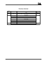
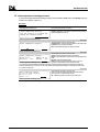
Revisions historical
Revision
index
A
B
§ concerned
Part 2 § 6.2, 7.4, 7.5 ;
8.9
General § 6.2
Part 1 § 2.4.2
Part 2 § 4.6
Part 2 § 5
C
D
DOCV211A001-D
Part 2 § 8
Part 2 § 9.1
Appendix A
Appendix B
Part 1 § 2.5
Appendix D
Modification descriptive
Date
Creation
Software update to version 2.3: Jacket temperature checking procedure
(Quality menu); addition of a memory resetting key (Configuration menu), spare
parts list adding.
Welcome screen: language selection at power on
Assisted edition function
Printer configuration menu
Program parameters configuration menu: detection parameters for up and
down time added
Alarms treatment with historical
Configuration menu of power on parameters
Printout examples updated
Description of the communication protocol of the RS 232C link
Modification of the Jacket Preparation menu
Manual mode available
00/04/01
FPP 5G & 5Gs User Manual
02/06/18
03/07/11
03/11/06
Page 3
ISL (C) copyright
The FPP5G/s Analyzers and this manual are protected by copyright.
Reproduction of the unit will result in prosecution.
All rights to the manual are reserved. Reproduction in any form, including in the form of excerpts, shall require written permission from the copyright
holder.
ISL FPP5G/s Software© 1999, ISL
This software is owned by ISL and is registered under the registration number IDDN.FR.001.250006.02.R.P.1999.000.30000 at the « Agence pour la
Protection des Programmes », 119 Avenue de Flandre - 75019 Paris. It is protected in France by the « Code de Propriété Intellectuelle » laws and
internationally by international treaty provisions, and all other applicable national laws. It must not be copied, reproduced, adapted, translated, rented or
disassembled. This also applies to the accompanying manuals.
INFORMATION
Information in this document is subject to change without notice and does not represent a commitment on the part of ISL. ISL provides this document "as
is", without warranty of any kind, either expressed or implied, including, but not limited to, the particular purpose. ISL may make improvements and/or
changes in this manual or in the product(s) and/or the program (s) described in this manual at any time. This product could include technical inaccuracies
or typographical errors. Changes are periodically made to the information herein; these changes may be incorporated in new editions of the publication.
Reproduction of any part of this manual without express written permission is forbidden.
Translation in foreign local language (other than French or English)
Translation in other language than French and English have no contractual value and have been performed under responsibility of the local distributor.
In any case the reference of the present literature will be the French and/or English release provided under ISL copyright.
Page 4
FPP 5G & 5Gs User Manual
DOCV211A001-D
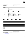
Reserved for public relations department
N° ................................
Date .............................
CUSTOMER
REPORT
PURPOSE
I wish to
Report an error
Submit a suggestion / a comment
Get more information
In the area of
Hardware
Software
Manual
ANALYZER ENVIRONMENT (please be complete)
• HARDWARE
Type of analyzer: ......................................
Serial N° : ...................................................
Options:
Parallel printer
Graphic printer
Plotter
RS232C interface
Current loop interface
Other : ......................................................
• SOFTWARE
Version : ........................................................
ATTACHED SHEETS
Listing
Diskette
Drawing
Text
Other
PROBLEM DESCRIPTION / COMMENTS
SUBMITTED BY
Name :
Company :
Address :
Phone :
Fax :
Date:
Send this report to your local Sales office or to Groupe ISL - Service Clients
BP 70285
14653 CARPIQUET CEDEX FRANCE
Tel : (+33) 2.31.26.43.00 – Monday through Friday from 9 :00 a.m. to 5 :00 p.m. French Time
Fax : (+33) 2.31.26.62.93
Web: http://www.isl-france.com/
DOCV211A001-D
FPP 5G & 5Gs User Manual
Page 5
Page intentionally blank.
Page 6
FPP 5G & 5Gs User Manual
DOCV211A001-D
Caution
This ISL analyzer has been carefully designed, manufactured and inspected
for quality. It has been equipped with a number of safety features.
However, the use of this analyzer may involve the handling of solvents,
chemicals, and other potentially dangerous flammable, toxic, etc.) materials.
Please exercise caution when- handling these materials while operating the
analyzer.
Please:
•read the manual
•wear proper protective clothing
•perform all suggested service procedures
•use care to prevent accidents.
The manufacturer accepts no responsibility for any damage or liability arising
from the use of analyzers.
Use of Non-ISL Products and Accessories: Defects or damage that result from
the use of Non-ISL branded or certified Products, Accessories, Software or
other peripheral equipment are excluded from warranty.
DOCV211A001-D
FPP 5G & 5Gs User Manual
Page 7
Page intentionally blank.
Page 8
FPP 5G & 5Gs User Manual
DOCV211A001-D
Contents
GENERAL
11
1. INTRODUCTION
1.1.ISL COMPANY PROFILE
1.2.TYPOGRAPHICAL CONVENTIONS
1.3.ABOUT THIS MANUAL
2. TYPE OF ANALYZER
3. CARE IN USE
3.1.MEANING OF SYMBOLS
3.2.CARE IN THE USE OF TESTING AND CLEANING EQUIPMENT
3.3.PRECAUTIONS TO TAKE WHEN USING BUILT-IN COOLING ANALYZERS
4. UNPACKING AND INSTALLATION
4.1.CARE IN UNPACKING
4.2.INSTALLING THE FPP 5GS: UNLOCKING THE SHOCK-ABSORBER
4.3.CONNECTIONS
5. DESCRIPTION OF THE DEVICE
6. THE USER INTERFACE
6.1.FRONT PANEL
6.2.WELCOME DISPLAY AND LANGUAGE CHOICE
13
13
14
14
14
15
15
15
15
16
16
16
16
19
20
20
21
PART 1 USE OF THE FPP 5G/S WITH PRE-INSTALLED PROGRAMS
1-23
1. INTRODUCTION
2. THE FIRST TEST
2.1.PREPARING A SAMPLE
2.2.ASSEMBLING THE FILTRATION AND MEASURING ASSEMBLY
2.3.CHARACTERIZATION OF THE SAMPLE
2.4.TEXT ENTRY DISPLAY
2.5.PREPARING THE JACKET
2.6.INITIATING THE TEST
2.7.CLEANING THE EQUIPMENT
1-25
1-25
1-26
1-26
1-28
1-29
1-30
1-31
1-33
PART 2 ADVANCED USE OF THE FPP 5G/5GS
2-35
1. INTRODUCTION
2. SCREENS OF THE MAIN MENU
3. DISPLAYING RESULTS: THE "RESULTS" MENU
4. PRINTING OUT: THE " PRINT" MENU
4.1.PRINTING OUT RESULTS
4.2.PRINTING TEST AND CLEANING PROGRAM PARAMETERS
4.3.PRINTING OUT THE CALIBRATION TICKET
4.4.PRINTING OUT MEASUREMENTS IN PROGRESS
4.5.PRINTOUT TEST
4.6.PRINTER CONFIGURATION
5. CHOOSING A PROGRAM AND DISPLAY FOR THESE PARAMETERS: THE "PROGRAM" MENU
5.1.COOLING PROFILE : THE "COOLING PROFILE" MENU
5.2.VACUUM PROFILE: THE "VACUUM PROFILE" MENU
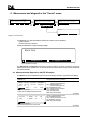
6. MEASUREMENT AND DIAGNOSTICS: THE "SERVICE" MENU
6.1.MEASUREMENT AND DIAGNOSTIC ON THE FPP 5G ANALYZER
6.2.MEASUREMENT AND DIAGNOSTIC ON THE FPP 5GS ANALYZER
7. ADJUSTMENT AND CALIBRATION: THE "QUALITY" MENU
7.1.SAMPLE PROBE CORRECTION TABLE: THE "CORRECT TABLE" MENU
7.2.CALIBRATION OF SAMPLE TEMPERATURE MEASUREMENT : THE "SAMP. T. CALIB." MENU
7.3.CALIBRATION OF JACKET TEMPERATURE MEASUREMENT: THE "JACK. T CALIB." MENU
7.4.CALIBRATION OF VACUUM CIRCUIT: THE "VACUUM CALIB." MENU
7.5.JACKET TEMPERATURE CHECKING PROCEDURE
2-37
2-37
2-39
2-41
2-42
2-42
2-43
2-43
2-43
2-44
2-45
2-48
2-50
2-52
2-52
2-54
2-57
2-58
2-58
2-60
2-61
2-62
DOCV211A001-D
FPP 5G & 5Gs User Manual
Page 9
8. ALARM TREATMENT
8.1.TYPES OF ALARM
8.2.DISPLAYING ALARMS, STOPPING THE BUZZER
8.3.ALARM PROCESSING
8.4.ALARMS HISTORICAL
9. CONFIGURATION: THE "SETUP" MENU
9.1.POWER ON PARAMETERS: THE "PWR.ON" MENU
9.2.CONFIGURING RESULTS DISPLAY: THE "DISPLAY" MENU
9.3.CONFIGURING ALARMS: THE "ALARM" MENU
9.4.FAULTS AND INDICATIONS
9.5.PERSONALIZATION AND ACCESS AUTHORIZATION TO LEVEL 1 : THE "LABO." MENU
9.6.PRINTER CONFIGURATION: THE " PRINTER" MENU
9.7.FPP 5G/S PC COMMUNICATION: THE "PC LINK" AND "RS232" MENUS
9.8.DATE/TIME SETTING : THE "CLOCK." MENU
9.9.THE "SERVICE" MENU
10. ACCESS LEVELS AND PASSWORD : THE "ACCESS" MENU
11. CLEANING PROGRAMS: THE "CLEAN." MENU
2-63
2-63
2-63
2-63
2-64
2-65
2-66
2-66
2-66
2-67
2-70
2-70
2-70
2-72
2-72
2-76
2-77
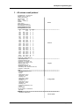
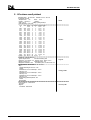
APPENDIX A - EXAMPLES OF PRINTOUT TYPES
79
1 - 40 COLUMN RESULT PRINTOUT
2 - 80 COLUMN RESULT PRINTOUT
3 - 80 COLUMN INTERNAL PARAMETER PRINTOUT
4 - 80 COLUMN CALIBRATION TICKET PRINTOUT
5 - 80 COLUMN MEASUREMENT PRINTOUT
6 - 80 COLUMN TEST PRINTOUT
81
82
83
84
84
84
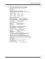
APPENDIX B - RS232 LINK FEATURES ON FPP 5G/S
85
1 - INTERFACE FEATURES
2 - OUTLET CONNECTOR BROACHING
3 - COMMUNICATION PROTOCOLS
4 - ENQ / ACK PROTOCOL DETAILS
5 - TRANSMITTED DATA
5.1 -MESSAGE FORMAT
5.2 -RESULT MESSAGES
5.3 -CONTEXT MESSAGE
5.4 -PROGRAM MESSAGE
5.5 -COOLING PROFILE MESSAGE
5.6 -VACUUM PROFILE MESSAGE
5.7 -RS 232C LINK CHECK MESSAGE
6 - RS232 COST
87
87
88
89
90
90
91
91
92
92
93
93
93
APPENDIX C - DIAGRAMS
95
1 - TEST LAUNCH DIAGRAM
2 - ACTION CHART
97
98
APPENDIX D - MANUAL MODE
99
1 - PREPARING THE TEST
2 - TEST RUNNING IN MANUAL MODE
102
103
INDEX
104
SPARE PARTS LIST
Page 10
DOCV211X200
FPP 5G & 5Gs User Manual
DOCV211A001-D
General
Page intentionally blank.
Page 12
FPP 5G & 5Gs User Manual
DOCV211A001-D
General
1. Introduction
1.1. ISL company profile
We would like to take this opportunity to thank you for choosing ISL product. We are confident that you will be
completely satisfied with your new Analyzer and we hope that you continue to call on us for all of your laboratory’s
petroleum testing needs. Before you begin, we ask you to take a few minutes to become acquainted with ISL and its
history.
ISL’s beginnings go back to 1975, when a group of engineers and scientists from the heart of the Northern France’s
petrochemical industry began seeking ways to automate petroleum testing. The neighboring industry served as an
excellent research and development proving ground for their new equipment.
By the end of 70’s, several quality instruments had been developed and were being marketed in Europe under
ATPEM Trademark.
The most famous of these new instruments was the CPP 97, Automatic Cloud and Pour Point Analyzer. Introduced
in the early 1980’s, its successor, the CPP97-6, revolutionized cold flow testing enabling up to six tests automatically
and simultaneously.
Adding new automatic instruments each year, ATPEM soon became a world-wide leader in automatic petroleum test
instrumentation. In 1986, they expanded operations, reorganizing into the company now knows as ISL.
Striving to maintain close contact with customers in over 75 countries, ISL has since grown, founded Sales & Service
branches on each continent. With design, marketing, service and support operating together under the ISL roof, the
company reached “a new dimension” in 1993 by obtaining ISO 9002 certification from the BVQI. Working hard to
extend our quality assurance program, we received ISO 9001 certification in 1995.
Though best known for distillation, viscosity testing, cold behavior instrumentation, flash point, evaporation loss,
oxidation, and asphalt testing equipment, ISL's contributions to automated petroleum testing continue to grow. With
more than 10 patents to date, ISL's constant research into new technologies buttresses our precedent for ultimate
precision, performance and safety. The company now offers over 20 Automatic Analyzers for different applications
giving incontestable benefits to its users in increasing of test precision by elimination of operator subjectivity and
human errors, while increasing productivity and reduce operator time with highest level of safety.
A worldwide distribution network supports our customers with quick, efficient service, and our highly knowledgeable
service staff buttresses this relationship, providing solutions to product or application challenges.
Please visit our web site for more information: http://www.isl-france.com .
DOCV211A001-D
FPP 5G & 5Gs User Manual
Page 13
FPP 5G & FPP 5Gs
1.2. Typographical conventions
Convention
Meaning
Bold
Important words or phrases
Bold Italics
Menus or buttons on the LCD
Bold + SMALL CAPITALS
Keys on the front panel of the device
1.3. About this manual
This manual is made up of two main parts, entitled:
1. Part 1: Using the FPP 5G with the pre-installed program.
2. Part 2: Advanced use of the FPP 5G
The first part allows the operator to carry out an initial plugging test with the FPP 5G in a few stages, confidently and
with no particular prior knowledge.
The second part, on the other hand, makes it possible to use the FPP 5G's potential to the full. It is, therefore,
intended for the knowledgeable user who is familiar with low temperature plugging tests. In any case, the sensitive
parts of the FPP 5G control software, those linked to the test parameters, can be read & write-protected by a system
of passwords chosen by the user.
There are two FPP models:
• The FPP 5G, an external cooling analyzer.
• The FPP 5Gs, a built in cooling analyzer.
The two models are similar and will be described as one (FPP 5G/s) throughout the manual. However, the special
characteristics of each model will be explained where necessary.
2. Type of analyzer
The FPP 5G makes it possible to determine the filterability limit temperature of medium distillates, including those
containing fluidification agents and other additives. It will be recalled that the filterability limit temperature, or CFPP, is
the highest temperature at which a given device when it is subjected to cooling in standard conditions (ref. NF EN
116).
The special feature of the present device is that it is very multi-functional, in that all its parameters can be re-set. It can
thus, over and above the program governed by the NF EN 116 standard (standard pre-installed CFPP test, as well
as four other programs) run programs based on the personalized parameters and linked to the needs of the user.
This major trump card allows the device to be used not only for the usual tests but also in the R & D area. What is
more, this multi-functionality has not been achieved at the expense of ease of use. Indeed, as we shall see in the
following chapters, the multi-functionality of the device is equaled only by ease of use.
Finally, it should be noted that the device has an electronic vacuum regulation system, which significantly improves
the accuracy of the tests and considerably reduces the weight, fragility and complexity of the device.
ISL has taken great care with the design and manufacture of this device and hopes it will give you every satisfaction.
Page 14
FPP 5G & 5Gs User Manual
DOCV211A001-D
General
3. Care in use
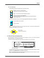
3.1. Meaning of symbols
Note
Important comment.
ATTENTION !
Call for particular care.
Referral
Referral to a particular document (Standards) or to another manual.
3.2. Care in the use of testing and cleaning equipment
It is supposed that operators are familiar with the handling of hydrocarbon products and that they are thus aware of
the dangers and risks that attach to them.
3.3. Precautions to take when using built-in cooling analyzers
Built-in cooling analyzers comprise a cooling compressor that necessitates several special precautions to be
respected for the long life of the analyzer and its optimum performance:
•Avoid using the analyzer on a vibrating surface. Surface vibrations can enter into resonance with those of the
compressor and cause damage to the analyzer.
•The optimal operating temperature for the analyzer is around 20°C. To avoid harmful overheating of the unit:
1.Keep the rear of the unit clear to allow heat to escape easily.
2.Keep the ventilation holes in the side of the unit clear. They must be regularly blown clear of dust to avoid
clogging and possible blocking.
DOCV211A001-D
FPP 5G & 5Gs User Manual
Page 15
FPP 5G & FPP 5Gs
4. Unpacking and installation
4.1. Care in unpacking
After unpacking, check the device and its accessories as well as any possible damage sustained in transit, which
must immediately brought to the attention of the carrier so that a statement of damage can be made.
The various parts of the FPP 5G/s are carefully checked and tested before shipping. Nevertheless, it is worth
checking that the equipment received corresponds to the packing list enclosed.
On taking delivery of the FPP 5G/s, unpack all these parts.
Put the analyzer on a work bench near electrical sockets and connections to cold sources. Allow enough space for
access to the rear connectors.
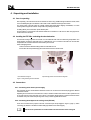
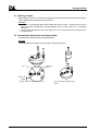
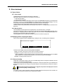
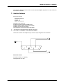
4.2. Installing the FPP 5Gs: unlocking the shock-absorber
The FPP 5Gs cooling compressor is mounted on a shock-absorber that must be locked during transportation. The
shock-absorber is locked by bolts that screw in underneath the unit. To ensure that the bolts are removed after
transportation the unit will not sit flat on its base until they are removed.
When unwrapping the unit:
1.Remove the shock-absorber locking bolts from underneath the unit.
2.Screw them into the special storage panel at the back of the unit as shown below.
Shock-absorber locking bolt
Special storage panel for shock-absorber locking bolts.
Figure 1: Locking/unlocking the shock-absorber
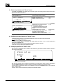
4.3. Connections
4.3.1. Connecting to the electric power supply
After unpacking the FPP 5G the different extensions need to be connected and it should be plugged into different
networks and circuits.
Regarding the connection of the FPP 5G/s to the mains, it should be noted that the device is built to operate from 90
to 130 Volts and from 180 to 250 Volts, at 50 or 60 Hz, in accordance with the majority of countries where the device
is marketed. The power cable corresponding to the country of sale is supplied with the device.
4.3.2. Connecting the analyzer to the cooling circuit (FPP 5G)
There are two nozzles for this purpose at the rear of the device (see the photograph in Figure 2, page 17). When
connecting, pay attention to the inlet and outlet markings (indicated on the nozzle support).
Refer to the ISL specifications for further details of the characteristics of the coolingunit.
Page 16
FPP 5G & 5Gs User Manual
DOCV211A001-D
General
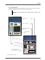
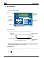
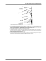
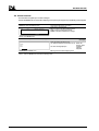
4.3.3. Connecting the printer
A parallel port is provided at the back of the analyzer for connecting a printer compatible with the Analyzer
(using ESC/P language) with which to print out test results, among other things.
Caution! The Analyzer and peripherals must be switched off before connecting any new
peripherals.
FPP 5G
"Service" Port
Parallel port - Printer
ALAN network inlet and
outlet
Cooling circuit inlet and
outlet
Logic card ventilator
Mains switch and
socket
Cooling unit ventilator
Shock-absorber fixing panel with
the two blocking bolts in place
FPP 5Gs
Figure 2: Rear panels and connections
DOCV211A001-D
FPP 5G & 5Gs User Manual
Page 17
FPP 5G & FPP 5Gs
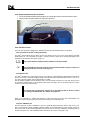
4.3.4. Sample temperature probe connection
1. Connect the sample temperature probe DIN plug to the corresponding socket on the front panel of the device.
2. Insert the probe in the probe-holder on the upper part of the device .
Probe holder
Vacuum tube rest
Sample temperature
probe socket
Figure 3: Sample temperature probe connection
4.3.5. FPP 5G/s / PC link
The FPP 5G/s Analyzer is fitted with an RS232C interface and an RS485 interface as standard.
®
4.3.5.1.Connection to the Alan network (RS 485 link)
The Alan® network allows among others one or more devices to be run by a PC using software specially
developed by ISL. The connection to the Alan® network is done by means of two ports (input/output) in the
back side of the Analyzer (see Figure 2 page 17).
Refer to Alan® Software installation manual and follow on line help available.
Note: The RS 485 communication mode has to be parameterized. Refer to the Part 2 section 9.7.2
- Setting up the PC link: "PC Link" menu page 2-71.
4.3.5.2.RS 232 C link
The Alan® network input / output ports may be connected via a special adapter supplied with the analyzer
to form an RS 232 C serial link enabling results to be collected to the delimited ASCII format on a PC or on
any other computer system and for transmission to a LIMS.
Use the adapter supplied (see the Packing List): it has two RS 485 connectors on one side, which have to
be connected simultaneously to the Analyzer’s Alan input and output, and on the other side an RS 232C
connector to be connected to the PC.
Note: The RS 232C communication mode has to be parameterized. Refer to the Part 2 section
9.7.1 - Setting up the RS232C link: the "RS232" menu page 2-70.
Refer to the Appendix B - RS232 link features on FPP 5G/s page 85 for the link characteristics, the
description of the communication protocol and the meaning of the messages and .
4.3.5.3.The "SERVICE" port
The FPP 5G/s has a serial « SERVICE » port as a standard fitting with which, with the help of the « ISL
UDS » maintenance software supplied, software updates can be downloaded via a PC and the contents of
the memory such as the internal parameters and results can be saved for subsequent reloading (refer to
the Part 2 section 9.9.4 - File upload/download commands: the "UDS" menu page 2-73).
Page 18
FPP 5G & 5Gs User Manual
DOCV211A001-D
General
5. Description of the device
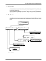
The FPP 5G/s consists, broadly speaking, of two major parts:
• The user interface.
• The filtration bank and the electronic and mechanical parts linked to it.
The user interface will be the subject of the next paragraph.
As regards the filtration bank, we will here only deal with the parts handled by an operator in the context of an CFPP
test (or one of the other four tests pre-installed in the device memory at the factory).
The equipment necessary for a CFPP test (in direct contact with the sample) is strictly compliant with the current
standard.
The FPP 5G/s consists of:
1.
A cylindrical, flat bottomed, transparent glass Testing tube with a permanent mark corresponding to a volume
of 45 ml; designed to contain the sample.
2.
A flat bottomed brass cylinder forming a sealed air bath, called (in compliance with the standard) a Jacket,
designed to contain the Testing tube, so as to heat and cool it. In the case of the FPP 5G/s, the Jacket is of a
piece with the Cooling bath. To maintain this bath at the desired temperature, the FPP 5G must be linked to a
coolingunit, in order to keep to the requirements of the current standard.
3.
So as to insulate the Tube from the Jacket (since the temperature change must occur across the air bath and
not by contact), there is a one-piece assembly consisting, from bottom to top, of an Insulating ring and two Ring
wedges. The insulating assembly is made of an oil-resistant plastic material; the different parts are held
together by stainless steel rods.
4.
A Stopper adapted to the testing tube by means of clips (ISL improvement).It is made of an oil-resistant plastic
material (see Figure 7 on page 1-26).
5.
A pipette and filtration assembly, strictly compliant with the current standard (see Figure 9 on page 1-27).
6.
A standardized and calibrated Temperature probe.
7.
Finally, a Vacuum source equipped with an electronic Vacuum regulator.
•Refer to the text of standard NF EN 116 for further details.
•See on Part 2 section 7 - Adjustment and calibration: the "Quality" menu on page 2-57 for the
temperature probe calibration procedure.
DOCV211A001-D
FPP 5G & 5Gs User Manual
Page 19
FPP 5G & FPP 5Gs
6. The user interface
6.1. Front panel
The front panel of the device appears thus:
Back-lighted 8-line
LCD
Activation keys
for menus or
buttons displayed
on LCD
LCD navigation key
Keys : Stop,
Reset and Alarm stop
Numeric keypad
and CANCEL
and ENTER keys
Direction keys
Figure 4: Front panel.
6.1.1. The LCD screen
The front panel of the device therefore includes an 8-line LCD which may be represented thus:
Button calling for
entry of a numeric or
alphanumeric value
Returns one level
in the display
hierarchy
Next display
Previous display
Figure 5: General operation of display and menus
Menu activated by key
immediately below (see
Figure 4).
On either side of this display, two keys make it possible to travel up and down the hierarchy of screens (activate the
NEXT SCREEN and PREVIOUS SCREEN keys – see Figure 3). In the lower part of the display, there are four keys by
means of which the menus displayed on the display can be activated.
6.1.2. Backlight setting
The LCD screen backlight is set by a combination of the ENTER KEY and the high DIRECTION KEY for less contrast
and low DIRECTION KEY for more contrast (refer to the next section).
Note: The intensity of the backlight can change according to the ambient temperature.
Page 20
FPP 5G & 5Gs User Manual
DOCV211A001-D
General
6.1.3. The control keys
The lower left hand side of the front panel is taken up by three keys, namely:
TEST
STOP/TEST: To stop a test or any other operation
If the LED is lit up, this means that a test is in progress.
STOP
RESET : To cancel and go up through the display/menu hierarchy
R
Interrupts the audible alarm signal. (ALARM STOP)
If the LED is lit up, this means that a problem has arisen. Pressing on this button will give
the error message content.
The rest of the front panel is occupied by a numeric keypad equipped with a CANCEL KEY and an ENTER key:
ENTER key: validate an input of variables.
ENT
TO CANCEL characters.
Finally, in the lower left hand section, there are four direction keys used to move around a text field and select
characters to enter variables (e.g. name of sample).
DIRECTION keys.
Scrolling of test result suctions.
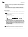
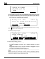
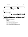
6.2. Welcome display and language choice
When the analyzer is switched on, the welcome screen is displayed. If it does not, first check the backlight
settings (see section 6.1.2 on the previous page).
This screen provides information about ISL and two menus offering the choice of language.
I
S
L
Zi Verson
14790 VERSON
FRANCE
www.isl-france.com
Tel:(+33) 2 31 26 43 00
Fax:(+33) 2 31 26 62 93
English
Français
Figure 6: Welcome display.
This display remains active until the key corresponding to the language of your choice is pressed. Doing this activates
the display 1 of the CFPP Run/Start menu (see Diagram 1 page 1-25).
Note: You can disable the language choice as part of the startup parameters (refer to the Part 2 section 9.1 page 266). If the choice is locked, press any key on the front panel.
DOCV211A001-D
FPP 5G & 5Gs User Manual
Page 21
FPP 5G & FPP 5Gs
Page intentionally blank.
Page 22
FPP 5G & 5Gs User Manual
DOCV211A001-D
Part 1
Use of the FPP 5G/s with
pre-installed programs
Page intentionally blank.
Page 1-24
FPP 5G & 5Gs User Manual
DOCV211A001-D
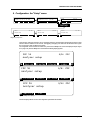
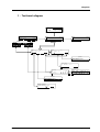
Use of the FPP 5G/s with pre-installed programs
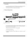
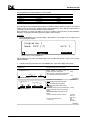
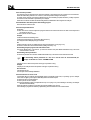
1. Introduction
The multi-functional nature of the FPP 5G/s is shown, as discussed previously, by the fact that it is possible to carry
out, over and above tests complying with the current standard (in this case standard NF EN 116), a personalized test
programs based on specific inputs.
In this part, we will focus on a standard test, i.e. the CFPP test. This test is, along with four others, pre-installed at ISL.
They are saved in a memory that is very easily updated (e.g. to change a name) by downloading from a PC via the
ALAN network.
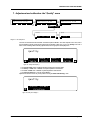
2. The first test
In this chapter we will deal with a CFPP standard test carried out with the FPP 5G, stage by stage. We will, however,
only describe the menus that are strictly necessary for the successful operation of the test. We will further assume that
the operator has taken due note of the care that needs to be taken with the substances tested and of cleaning
products.
I
S
L
Zi Verson
14790 VERSON
FRANCE
English
Sample:
Prog
Jacket
Prepar.
Sample
Français
Sample:
No:
: 1 CFPP (°C)
www.isl-france.com
Tel:(33) 2 31 26 43 00
Fax:(33) 2 31 26 62 93
Prog
Op:
Op:
°C
Start
now
No
No:
: 1 CFPP (°C)
Cloud
Prog.
Start
now
Oper.
Operator
_
ABCDEFGHIJKLMNOPQRSTUVWXYZ °#&\|@[]^~:
abcdefghijklmnopqrstuvwxyz +*/=<>()’"%
OK
Delete
Insert
Select a program
Name: CFPP (°C)
No:
OK
ID:
Status: Running
26.0°C
Test:
Jack:
Next
-34.0°C
12/05/1999 14:12
Up:
s
Dwn:
s
Unit:°C
Details
Sample temp.: -17.5°C
Time
Durat.
Up Down Temp.H t.H
t-1<->t (s) (s)
(°C)
(s)
t0->t
40'41
3'46
41
9
-15.7
80
Test: 28/ 28 at -17 °C Next:-18°C
Sample ID
_
ABCDEFGHIJKLMNOPQRSTUVWXYZ °#&\|@[]^~:
abcdefghijklmnopqrstuvwxyz +*/=<>()’"%
OK
Delete
Insert
Status: idle mode
Tmp: 25.0°C
Jacket setup: 25.0°C
-34.0°C
Next setpoint
Step
Value
Apply
Diagram 1: Starting a test.
DOCV211A001-D
FPP 5G & 5Gs User Manual
Page 1-25
FPP 5G & FPP 5Gs
2.1. Preparing a sample
Before initiating the test phase, a sample must be prepared. It will be remembered that the FPP 5G/s is intended for
medium distillates and is not suitable for other hydrocarbons.
Procedure:
1. By means of a non-fluffy paper filter (products certified with reference number – standard NF EN 116), about
50ml of the sample at the laboratory's ambient temperature, but in any case not below 15 C° (ref. Standard
NF EN 116).
2. Pour the sample thus filtered into the empty testing tube, as far as the permanent level marking (a volume
equivalent to 45ml).
2.2. Assembling the filtration and measuring assembly
The filtration and measuring assembly is assembled as follows :
Procedure
1. Insert the pipette into the stopper as shown in Figure 7 and Figure 8 see above.
Vent
Space for the
pipette
Space for the
sample
t
t
Figure 7: Stopper, 3D view and view from above
Page 1-26
Figure 8: Positioning of the Pipette on the
stopper.
FPP 5G & 5Gs User Manual
DOCV211A001-D
Use of the FPP 5G/s with pre-installed programs
Pipette
Upper wheel nut
Conical seal holder
O-ring
Cylindrical seal holder
O-ring
Strainer body
O-ring
Ring
Strainer filter
Web support
Filter tightening nut
Figure 9: Assembly of filtration assembly, with parts list.
2. When the pipette is introduced into the stopper, insert into it: The upper wheel nut, the conical seal holder, the first
O-ring, the cylindrical seal holder and the second O-ring, before introducing the assembly into the strainer body
and tightening. Assemble the rest of the filtration assembly as per Figure 9 on page 1-27.
3. Put the filtration assembly into the testing tube, having previously filled it.
4. Carefully push the filtration assembly-pipette-stopper assembly into the testing assembly until they clip together. To
remove the stopper, push in the direction opposite to that used to achieve mounting. Make sure that the filtration
assembly is right at the end of the testing tube.
5. Fix the vacuum pump tube at the free end of the pipette.
6. Place the measuring assembly (consisting of the pipette, the stopper and the filtration assembly) into the receptacle
intended for this purpose, to the right of the jacket and called the Measuring Head Port.
DOCV211A001-D
FPP 5G & 5Gs User Manual
Page 1-27
FPP 5G & FPP 5Gs
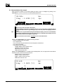
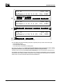
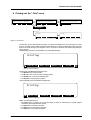
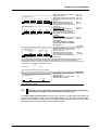
2.3. Characterization of the sample
When the device is switched on, the welcome display per Figure 6 page 21 is displayed. By pressing on the
STOP/TEST key on the front of the device, the following display appears thus:
ID Éch:
Prog : 1 CFPP (°C)
Jacket
Prepar.
Sample
No:
Op:
No
Start
now
Figure 10: Display 1 of the FPP Run/Start menu.
There are two points to be made in this respect :
After switching on the device, the display of the FPP Run/Start menu above is obtained after the
language has been chosen or by pressing any key on the front panel if the language has been
locked.
This screen is not placed hierarchically after the Welcome display. The arrow on the left bottom
of the display, the PREVIOUS LEVEL key (refer to the section 6.1.1 page 20), allows backing up on the
main screens level (refer to the Diagram 2 page 2-37).
These measures have been taken to accelerate access to test-related menus.
Display 1 of the FPP Run/Start menu contains the following information:
• Sample : identifying name of the sample
• No : sample number
• Prog : the program being used and the unit used for temperature measurement.
• Op : name of the operator
• The following menus and buttons:
Jacket Prepar.: jacket preparation menu
Sample: Sample ID entry button
No: Sample number entry button
Start now: Start test button
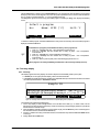
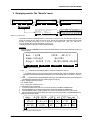
Display 2 of the FPP Run/Start menu, accessible via the next display button, has, in its upper part, the same fields as
the previous screen, and these buttons in its lower part :
Cloud : Button for cloud point entry.
Prog. : Program selection menu.
Oper. : Operator name entry button.
Start now: Start test menu.
ID éch:
No:
Prog
Op:
: 1 CFPP (°C)
°C
Cloud
Prog.
Oper.
Start
now
Figure 11: Screen 2 of FPP Run/start menu.
Page 1-28
FPP 5G & 5Gs User Manual
DOCV211A001-D
Use of the FPP 5G/s with pre-installed programs
With the Cloud button in display 2 of the FPP Run/Start menu, the sample cloud point temperature can be entered
directly by means of the numeric keypad. In fact, if the cloud point temperature is known, the test could start with that
plus x°C (x being a program parameter - x ≥ 5°C for a standard CFPP test).
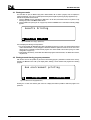
The Prog. button gives a choice of factory pre-installed programs. Activating the Prog. menu displays the following
screen :
Select a program
No:
Name: CFPP (°C)
OK
Unit:°C
Details
Next
Figure 12: Display 1 of the Prog. menu.
To select the desired program, activate the Next button as many times as necessary. When the desired program is
displayed, activate the OK button.
The FPP 5G/s has 5 programs pre-installed at the factory. These programs are:
1. CFPP (°C) : Standard CFPP test – Unit of temperature measurement °C.
2. Simul (°C) : Filterability test with constant rate of cooling of jacket - Unit of temperature
measurement °C.
3. CFPP (°F) : Filterability test - Unit of temperature measurement °F.
4. Simul (°F) : Filterability test with constant rate of cooling of jacket - Unit of temperature
measurement °F.
5. CFPP (°C) : Memory area for priority use for downloading programs from a PC.
All these programs are entirely modifiable (provided there is the necessary authority to do so).
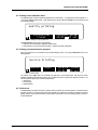
2.4. Text entry display
2.4.1. Text entry
This display is typical of text entry displays. It is found at all points and is essentially made up of two parts:
• A variable part, on the upper part of the display, which is the name of the field.
• A recurrent part (whatever the field is) consisting of an alphabetic table (from which the characters to be entered
are selected) and three buttons: OK, Delete and Insert .
Sample ID
_
ABCDEFGHIJKLMNOPQRSTUVWXYZ °#&\|@[]^~:
abcdefghijklmnopqrstuvwxyz +*/=<>()’"%
OK
Delete
Insert
Figure 13: Text entry screen. The field concerned is the sample identifying name (sample ID).
The characters are entered in the following way:
1. On the entry display, a black rectangle flashes on the first letter of the table ("A"). To select a letter, use the
direction keys on the front panel. Press the key as often as necessary (or keep the finger pressed on it) to indicate
the direction of the character sought.
2. When the flashing rectangle is positioned on the character sought, press the ENTER key on the numeric keypad. If
the character is incorrect, cancel it with the CANCEL key.
3. If there is a mistake in the string of characters entered, use the direction keys and the Insert and Delete buttons
to remedy it.
4. Finally, validate with the OK button.
DOCV211A001-D
FPP 5G & 5Gs User Manual
Page 1-29
FPP 5G & FPP 5Gs
Proceed in similar way for the operator name.
After validating (by means of the OK button in the text entry display), the initial display returns automatically to the
display 1 of the Run menu (see Figure 10, page 1-28). The same is true at each entry of text variables by means of
the text entry display.
2.4.2. Assisted edition
To speed up test starting the text entry screen enjoys a semi-automatic input feature: the latest text inputs are stored
in memory so that the operator only needs to enter the first two or three characters for the whole to be displayed.
If the function Auto Edition is activated, the Analyzer proposes a suite when characters are entered according to
prior enters. This function is intended for accelerate test initiating and it can be configured or deactivated (refer to the
Part 2 section 9.1 page 2-66).
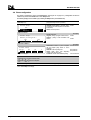
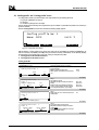
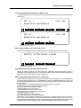
2.5. Preparing the Jacket
As indicated previously, in the FPP 5G, the jacket is of a piece with the cooling bath. Preparation of the jacket consists
of lowering the temperature to the first step of the cooling profile adopted, e.g. for a standard CFPP test (ref. standard
NF EN 116), this step is at the temperature of -34 ± 0.5 °C. The jacket can also be re-heated, if necessary, up to a
maximum of +50°C.
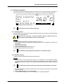
Procedure :
1. From the display 1 of the FPP Run / Start menu (see Figure 10 page 1-28), activate the Jacket Prepar menu.
The following display then appears :
Status: idle mode
Jacket setup : 25.0°c
Tmp: 25.0°C
-34.0°C
Next setpoint
Step
Value
Apply
Figure 14: Jacket Prepar. menu display.
2. The control program searches in the cooling profile of the program previously selected (see section 2.3 page 128) for the first step jacket setting and displays it. If the setpoint displayed meets the requirement of the tests,
press the APPLY key. The temperature setpoint is then displayed in the “Jacket setup:” field and the real jacket
temperature appears in the “Tmp:” field.
It is possible to go directly to the following step by pressing the STEP key (only after the first step was applied).
If the cooling profile does not include a jacket step, you will have to enter the desired temperature. Press the
VALUE key of the Next setpoint menu. Enter the temperature value of the desired step using the numeric
keypad, and validate with the ENTER key.
3. Initiate preparation of the jacket by activating the APPLY button. Otherwise activate the PREVIOUS LEVEL button (the
arrow on the left bottom). The effect of both these actions is to re-establish display 1 of the FPP Run / Start menu
(see Figure 10 page 1-28).
Do not forget to place the cover on the jacket so as to avoid condensation of water vapor inside it.
When the jacket has reached the set temperature, an audible signal is given.
If for any reason the preparation of the jacket must be stopped, simply press on the STOP/TEST button on the front
panel of the device. The control software will ask for confirmation of the command on the following display:
Page 1-30
FPP 5G & 5Gs User Manual
DOCV211A001-D
Use of the FPP 5G/s with pre-installed programs
Jacket preparation
Do you really want to stop ?
Yes
No
Figure 15: Confirmation that jacket preparation is to be cancelled
Confirm or cancel the command by activating the Yes or No buttons respectively.
To gain time, the Jacket preparation stage can be carried out first before even preparing the sample and
assembling the filtration assembly.
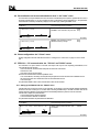
2.6. Initiating the test
After the audible signal for the end of the preparation of the jacket is sounded, carry out following operations:
Procedure
1.
2.
3.
4.
Remove the Jacket cover.
Place the insulating assembly at the bottom of the Jacket.
Remove the measuring assembly from the receptacle and place it in the Jacket.
Activate the Start now menu.
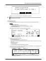
If all the stages have been carried out correctly, the display below will appear.
Status: Running
Test:
Jack: -34.0°C
12/05/1999 14:12
ID:
26.0°C
Up:
s
Dwn:
s
Figure 16: Display 1 Start now menu.
This display carries the following information :
• ID : Sample identification name
• Status : Operation under way, on this case the test is running.
• Test : During the test this field indicates the temperature of the sample at which the forthcoming suction will be
carried out.
• Jack : Jacket temperature.
• Current date and time.
• (In large characters) The sample temperature given by the probe.
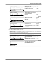
This screen gives access, by means of the Next Display button, to another display on which the progress and
details of the current test may be followed in real time.
Sample temp.:
Time
t0->t
Test:
26.0°C
Durat.
Up Down Temp.H t.H
t-1<->t (s) (s) (°C) (s)
0/
0 at
°C Next:
Figure 17: Display 2 Start now menu.
DOCV211A001-D
FPP 5G & 5Gs User Manual
Page 1-31
FPP 5G & FPP 5Gs
Display 2 of the Start now menu has the following components :
• Sample temp.: Temperature of the sample. This field is refreshed in real time.
st
• Time t0->t: Cumulative time from the 1 suction.
• Durat. t-1<->t: Time interval between two suctions.
• Up (s): Duration of the rise by suction of the sample in the pipette.
• Down (s): Duration of the descent of the sample in the testing tube.
• Temp.H (°C): Maximum temperature attained by a sample in a test.
• t.H (s): Time needed to attain temperature Temp.H from the beginning of the current suction.
• Test: __/__: Number of the suction displayed over the total number of suctions. In testing, it is always the last
suction that is displayed.
• at __°C: Temperature of the sample at the moment of suction.
• Next:: Temperature at which the next suction will be carried out.
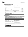
Sample temp.:
Time
t0->t
40'41
-17.5°C
Durat.
Up Down Temp.H t.H
t-1<->t (s) (s) (°C) (s)
3'46
41
9
-15.7 80
Test: 28/ 28 at -17 °C Next:-18°C
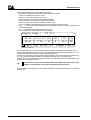
Figure 18: Example of test.
The FPP 5G/s will carry out, in accordance with the standard, a suction at each lowering of the temperature by 1°C.
If the cloud point temperature is known, the FPP 5G will undertake the first test at this temperature plus 5°C. If not ,
the first suction will be performed when the sample temperature reaches 10°C.
If the filter is not choked when the sample has reached a temperature of –20°C (the temperature of the jacket being 34 ± 0.5°C), the FPP 5G/s will automatically lower the Jacket temperature to (-51 ± 1)°C (second step).
If there is still no choking when the temperature has reached -51°C (third step), the FPP 5G/s control software stops
the test in accordance with the standard.
These parameters are those of the standard CFPP test (ref. NF EN 116). However, they may be
modified on condition that the necessary access authorizations have been given.
The personalization of the parameters, and the display and printing out of results will be dealt with in the second part
of this manual.
Page 1-32
FPP 5G & 5Gs User Manual
DOCV211A001-D
Use of the FPP 5G/s with pre-installed programs
2.7. Cleaning the equipment
At the end of each test the measuring assembly must be cleaned. This can be done manually or automatically. In
fact, the FPP 5G has two automatic cleaning programs. The programs are accessible from the Cleaning menu:
ID:
Jacket Preparation
Test:
Jack: 25.6°C
12/05/1999 14:12
26.0°C
Cleaning
Figure 19: Display 1 of the FPP Run/Display menu
The Cleaning menu is not accessible during testing.
2.7.1. Cleaning by hand
Manual cleaning is recommended by the standard (see Standard NF EN 116) and consists of complete disassembly
and cleaning of the filtration assembly.
Before each test it is necessary to check the condition of the filter. Choking of the filter by
paraffin crystals or other impurities may cause erroneous results.
Procedure
1. Disassemble the filtration assembly completely (see Figure 9, page 1-27).
2. Clean the filtration assembly, the pipette and the testing tube with a solvent appropriate to the nature of the
sample tested.
3. Dry the different parts carefully.
4. Check the condition of the filter.
5. Reassemble the assembly (see Figure 9, page 1-27).
The measuring assembly is now ready for use again.
If the metallic filter remains clogged after this treatment, it is advisable to change it.
2.7.2. Automatic cleaning
To initiate an automatic cleaning program, follow the procedure below:
Procedure
1. Fill two containers, of a base wide enough so that they are not unbalanced by the measurement assembly
(about 400 ml, similar to those constituting the measuring assembly receptacle), with two different solvents: one
for washing and the other for rinsing, in accordance with the products tested and the degree of cleanliness
desired.
It is assumed that the operator has taken all the precautions associated with the use of solvents
2. Remove the temperature probe from the stopper and put it in the probe port in the upper part of the device (See
Figure 3 on page 18).
3. Unclip the testing tube, which is to be cleaned separately .
4. Activate the FPP Run/Display menu, then the Cleaning menu, to call up the display below:
DOCV211A001-D
FPP 5G & 5Gs User Manual
Page 1-33
FPP 5G & FPP 5Gs
Cleaning No:1 <Name>
Select the next step
Done
Solv.1
Solv.2
Select.
Figure 20: Display 1 of the Cleaning menu
This display includes in its upper part the number of the automatic cleaning program in progress. Here it is program
N° 1. In the lower part of the display, two buttons give access to the two stages of cleaning and a third, Select, allows
a cleaning program to be selected and displayed. Completion of each stage will be indicated by "Done".
5. Immerse the measurement assembly in the container of the first solvent, and validate by activating the OK
button of the display below. Otherwise exit by means of the Exit button:
Cleaning No: 1 < Name>
Solvent 1
Immerse the pipette into the solvent
<Message>
Exit
Ok
Figure 21: Display 1 of the Solv.1 menu
Modification of the <Message> and <Name> fields are dealt with in Part 2 section 11 - Cleaning
programs: the "Clean." menu page 2-77.
After validating, the following screen appears :
Cleaning No: 1 <Name>
Status: Cleaning
0/5
150 mmH2O
Cycles
Depressure
+
-
Solvent 1
End
Figure 22: Display 2 of the Solv.1 menu
This display includes the following components:
• The number of the current program (permanent field).
• The current stage.
• The status, cleaning in progress.
• The number of cycles; this field may be modified directly by activating the Cycles button, in the course of
cleaning.
• Pressure reduction applied for suction of the solvent. This field may also be modified directly in the course of
cleaning, to allow the height of the solvent rise to be adjusted and the filtration assembly only to be cleaned, or the
whole measuring assembly by further reducing the pressure.
• With the End button the current cleaning stage can be definitively ended.
At the end of this stage the display in Figure 20 on page 1-34 appears. For solvent 2 exactly the same procedure is
followed.
At the end of each stage of the cleaning process, an intermittent alarm tells the operator that the operation has
finished.
A second program is available. This may be useful if there is a change in the type of sample, for example, which
might imply the use of different solvents and so a different number of cycles.
Page 1-34
FPP 5G & 5Gs User Manual
DOCV211A001-D
Part
2
Advanced use of
the FPP 5G/5Gs
Page intentionally blank.
Page 2-36
FPP 5G & 5Gs User Manual
DOCV211A001-D
Advanced use of the FPP 5G/5Gs
1. Introduction
This part deals with the advanced use of the FPP 5G, i.e. the setting of the device according to the needs of the user.
As previously indicated, this presupposes that the user is familiar with the techniques of plugging tests.
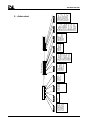
The FPP 5G settings are accessible from the main display (see following paragraph).
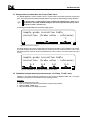
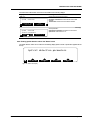
2. Screens of the main menu
I
S
L
BP 40
14790 VERSON
FRANCE
www.isl-france.com
Tel:(33) 2 31 26 43 00
Fax:(33) 2 31 26 62 93
English
FPP 5G
S/N: 212
Software V 2.4/ 2.4 (C)
FPP Run
Start
Display
ISL, 1999
⊕
Results
Access
Français
FPP 5G
S/N: 212
Software V 2.4/ 2.4 (C)
Print
Program
ISL, 1999
Service
Quality
FPP 5G
S/N: 212
Software V 2.4/ 2.4 (C)
Setup
ISL, 1999
Clean.
Main menu
Sample:
Prog
Jacket
Prepar.
Sample:
No:
: 1 CFPP (°C)
Sample
Prog
Op:
No
No:
: 1 CFPP (°C)
Op:
°C
Start
now
Cloud
Prog.
Oper.
Start
now
Diagram 2: Access to the main display level.
The main level display is the highest hierarchically speaking. It is not directly accessible when the device is switched
on. To access it, after switching the device on and pressing on any button, it is necessary to go up one display level.
Diagram 2 above shows how access to this level operates.
If the user has operator access, a very simple menu is available to him (
):
The user can run and follow a test.
The user can display and print a result.
If the user has Laboratory (Labo.) or Maintenance (Maint.) access, the complete menu is available
( + + )
DOCV211A001-D
FPP 5G & 5Gs User Manual
Page 2-37
FPP 5G & FPP 5Gs
FPP 5G
Software V 2.4/ 2.4 (C)
FPP Run
Start
Display
Results
FPP 5G
Software V 2.4/ 2.4 (C)
Print
Program
Access
S/N: 212
ISL, 1999
Service
FPP 5G
Software V 2.4/ 2.4 (C)
Setup
S/N: 212
ISL, 1999
⊕
Quality
S/N: 212
ISL, 1999
Clean.
Figure 23: The three displays of the main level with access level 1 or more.
The main display level includes the following components, respectively from top to bottom and from left to right:
• The name of the analyzer.
• The serial number of the analyzer.
• The version of the control software / and dialog boxes.
The menus of the main level are : FPP Run/Start & FPP Run/Display, Results, Print, Program, Service, Quality,
Setup, Access and Clean. These menus will be dealt with in detail in the paragraphs following.
It should be noted, however, that the FPP Run (Start and Display) menu was covered almost in its entirety in Part 1.
In the following we shall assume that the access level is level 1 (Labo level). This level allows access to the settings
associated with tests, making it possible to modify them and thus design personalized programs that respond to
specific needs. The access levels will be dealt with through the Setup menu.
Page 2-38
FPP 5G & 5Gs User Manual
DOCV211A001-D
Advanced use of the FPP 5G/5Gs
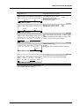
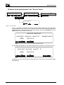
3. Displaying results: The "Results" menu
FPP 5G
S/N: 212
Software V 2.4/ 2.4 (C)
Start
FPP Run
Display
ISL, 1999
Results
FPP 5G
S/N: 212
Software V 2.4/ 2.4 (C)
⊕
Access
Print
Program
ISL, 1999
Service
Quality
FPP 5G
S/N: 212
Software V 2.4/ 2.4 (C)
Setup
ISL, 1999
Clean.
Results
Res. :2/28 CFPP: -18°C at filling up
Samp.:Diesel
No:001
Prog.: 1CFPP (°C) 12/05/1999 09:40
Print
Prev.
Next
Transm.
Res. :2/28 CFPP: -18°C at filling up
Time
Durat.
Up Down Temp.H t.H
t-1<->t (s) (s) (°C) (s)
t0->t
42'30
4'30
60
-14.2 50
Test: 15/ 15
at -18.0°C
Diagram 3 : The Results menu
Test results are stored in a dedicated memory. The FPP 5G can store up to 50 test results (this depends on the
number of suctions per test). When the memory is full, the FPP 5G automatically compresses the first results
recorded. The results can be sent to a PC by the ALAN or the RS232C link ( see § 9.7 : FPP 5G/s
PC communication: the "PC Link" and "RS232" on page 2-70).
To display the results the following procedure should be followed:
Procedure :
1. Press the button for the Results menu; this calls up the display allowing access to all the results saved, which are
shown as follows:
Res. :3/28
Samp.:Diesel
Prog.: 1CFPP (°C)
Print
Prev.
CFPP: -18.0°C
No:001
12/05/1999 09:40
Next
Transm.
Figure 24: Ecran 1 du menu Results
• Res. : __/__: number of the result displayed over the number of results stored in memory
* : An asterisk appears in front of the result number if the test has been carried out despite the date of the
adjustment of the sample temperature measurement circuit was exceeded (refer to the section 7.2 page 258).
• CFPP : __: Limit temperature of sample filterability and the type of blockage (this information cannot be displayed
– See Display/Print detection parameters, Table 3 program on page 44).
• Samp. : Identifying name of the sample
• No : Sample number
• Prog. : The program chosen for the test.
• Date and time of the end of the test.
2. To access the desired result, press as many times as necessary on the Prev. and Next buttons.
3. Press the Print button to print out the result previously selected with the Prev. and Next buttons.
4. Press the Transm. button to validate a result so as to send it to the RS323C link or to the ALAN network.
5. When the desired result is achieved, details of the result may be viewed by pressing on the NEXT DISPLAY button,
which gives the following display:
Res. :2/28 CFPP: -18°C at filling up
Durat.
Up Down Temp.H t.H
Time
t0->t
t-1<->t (s) (s) (°C) (s)
42'30
4'30
60
-14.2 50
Test: 15/ 15at
-18.0°C
Figure 25: Display 2 of the Results menu
DOCV211A001-D
FPP 5G & 5Gs User Manual
Page 2-39
FPP 5G & FPP 5Gs
This screen, similar to the one in Figure 19 (on page 26), differs from it in the following respects:
Upper part of screen, (above table)
• Res. :__/__: sample ranking (e.g. result of test n°2 out of 28 carried out Res. : 2/28)
• CFPP : limit temperature of filterability of the sample
Lower part of screen, (below table)
• Test : __/__at __°C: Number of the suction displayed over the total number and the temperature at which they
were carried out.
6. Press on the UP or DOWN keys on the front panel to display the details of each suction.
The duration of the rise, the descent, tH, can be visualized in seconds or in one-tenth seconds (see section 9 page 265 for the configuration).
Page 2-40
FPP 5G & 5Gs User Manual
DOCV211A001-D
Advanced use of the FPP 5G/5Gs
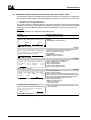
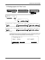
4. Printing out: the " Print" menu
FPP 5G
S/N: 212
Software V 2.4/ 2.4 (C) ISL, 1999
FPP Run
Start
Display
Results
⊕
FPP 5G
S/N: 212
Software V 2.4/ 2.4 (C) ISL, 1999
Access
Print
Program
Service
FPP 5G
S/N: 212
Software V 2.4/ 2.4 (C) ISL, 1999
Quality
Print
Setup
⊕
Printing
Printing
Results
Clean.
Run env
Quality
Stop
Service
Check
Setup
Stop
Diagram 4 : The Print menu
The FPP 5G/s can print out the following information : the results, the calibration ticket, or the parameters of a given
program. To be able to do this, make sure that the device is linked up to a printer compatible with analyzer (using the
PCL/3 or the ESC/P language) and configured “on line”. The printer is connected to the analyzer rear panel (see
Figure 2 page 17).
To initiate printing, activate the main level Print menu; this display will appear:
Printing
Results
Run env
Quality
Stop
Figure 26: Print menu Display 1
The first screen of the Print has the following menus:
• The Results menu, to print out results.
• The Run env. menu, to print out a test or cleaning program.
• The Quality menu, to print out the calibration ticket.
• The Stop button, to stop printing in progress.
The second display of the menu Print menu appears thus:
Printing
Service
Check
Setup
Stop
Figure 27: Print menu Display 2
Display 2 has the following menus:
• The Service menu, for printing out, among other things, the values of measurements in progress (sample
temperature, jacket temperature and cryostat)
• The Check menu, to check the printer link.
• The Setup menu, to set the printer parameters.
• The Stop button, to stop printing in progress.
DOCV211A001-D
FPP 5G & 5Gs User Manual
Page 2-41
FPP 5G & FPP 5Gs
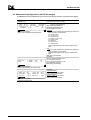
4.1. Printing out results
The FPP 5G/s can print, in different ways (with or without details, with or without program) and, as required, the
results of the last test, of any test, or of all the previous tests (see Examples of printout types page Appendix A-79).
Results can be printed out at two levels:
1. From the Results menu by activating the Print menu. At this level, the desired result can be printed out by
selecting it by means of the Next or Prev buttons.
2. From the Print menu (see Figure 23 on page 2-38). When the Results menu is activated, the following display
appears :
Results Printing
One res
All
Figure 28: Results menu Display 1 (Print menu)
From this display the following can be printed out :
• Any result. Activating the One res button calls up the display in Figure 24 on page 2-39. At this level the printout
mode is that described in 1 of this paragraph. It should be noted that a printout of a result can be set. Thus in the
printout result it is possible to include the test program used and/or details of the suctions. (See § 4.6: Printer
configuration on page 2-44)
• All the results in the memory. In this latter case neither the programs used for the tests, nor details of the suctions,
are printed out.
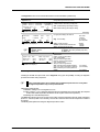
4.2. Printing test and cleaning program parameters
With the FPP 5G it is also possible to print the test and cleaning program parameters contained in the memory.
Activating the Run env menu calls up the display below, allowing a choice between test programs and cleaning
programs.
Run environment printing
Program
Cleaning
Figure 29: Run env menu display(Print menu).
Pressing one or other of the buttons gives access to a display that makes it possible to select the program to be
printed out.
Page 2-42
FPP 5G & 5Gs User Manual
DOCV211A001-D
Advanced use of the FPP 5G/5Gs
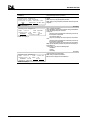
4.3. Printing out the calibration ticket
The calibration ticket can also be printed out (provided it is in access level 1 – see Appendix A section Appendix A - 4
-: 80 column calibration ticket printout – page Appendix A-84). Simply activate the Quality menu and from there call
up the following display:
Quality printing
Calibration
Ticket
Internal Param
40/80
80 col
Figure 30: Quality menu display (Print menu)
The Internal param. button gives a choice between :
• Taking into account the printer configuration (40/80 button).
• Always printing out in 80 columns (80 col button) – whatever the printer configuration.
4.4. Printing out measurements in progress
Print-out of Measures can be activated via the measures display screen or by using the Measures button in the
following display:
Service Printing
Measure
Regul.
Internal Param
40/80
80 col
Figure 31: Service Printing.
The contents of the Regul. menu are accessible only with level 2 access authorization. With this menu all the
regulation data linked to the following functions can be collected and sent to a printer (see Appendix A section 6 -80
column test printout page A-84) or another peripheral (PC):
• Jacket probe.
• Vacuum pump.
• Optical detectors.
4.5. Printout test
The Check button (see Figure 27 page 2-41) allows a test to be printed out to check the printer FPP 5G/s link (see
Appendix A section 6 - 80 column test printout page Appendix A–84). Moreover, this makes it possible to check the
printing quality of certain special characters (e.g. the degree symbol) which may not be printing properly because of
incorrect adjustment.
DOCV211A001-D
FPP 5G & 5Gs User Manual
Page 2-43
FPP 5G & FPP 5Gs
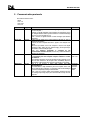
4.6. Printer configuration
The printer is configured by means of the Setup button (see Figure 27 on page 2-41). Configuration can also be
carried out by means of the Printer menu of the Setup menu.
The following displays can be called up by activating the Setup button (on the Print menu):
Display
Meaning of different menus
(Print / Setup menu).
(Going from left to right and from top to bottom).
Printer setup
YES
Automatic
Printing
lt
Setup menu display 1.
Check
Printer setting
Automatic result printing : Automatic printing Yes/No
of results at end of test (if a printer is connected
to the device).
Check : Printer test printout.
Next display
Results printing with :
Program : printing of program used for the test. Yes/No
Suctions : printing of data associated with
Yes/No
suctions
Printer setup
Results printing with :
YES
YES
Program
Field values
Suctions
Setup menu display 2.
Printer setup
40 col
18
Printer
Red
Select
code
Setup menu display 2.
91
2
Degree
code
Line
feeds
Printer Select : selection of a printer compatible
with the analyzer (using ESC/P or PCL/3
language)
Red code : code for printing in red
Degree code : ASCII code designating
"degree" code (see printer doc.).
Line feeds : number of line feeds after printing.
Next display
40 or 80 columns
See printer doc.
See printer doc.
0 to 5 or form feed
E.g. :
Configuration of a 40 column CITIZEN® printer:
40
18
91
2
Configuration of an 80 column EPSON® printer:
80
248
2
For the exact configuration, however, reference must be made to the manual supplied by the printer manufacturer.
Table 1: Print / Setup menu display
Page 2-44
FPP 5G & 5Gs User Manual
DOCV211A001-D
Advanced use of the FPP 5G/5Gs
5. Choosing a program and display for these parameters: the "Program"
menu
FPP 5G
S/N: 212
Software V 2.4/ 2.4 (C) ISL, 1999
⊕
FPP Run
Start Display Results
Access
FPP 5G
S/N: 212
Software V 2.4/ 2.4 (C) ISL, 1999
Print
Program
Service
Quality
FPP 5G
S/N: 212
Software V 2.4/ 2.4 (C) ISL, 1999
Setup
Clean.
Program
Program No: 1
Name: CFPP (°C)
Unit:°C
Details
Next
Program No: 1
Program No: 1
Program No: 1
-70.0°C
Alarm
-51.0°C
Stop
60s
Maximum
Up-time
10s
Allowed
Down-t
CFPP (°C)
°C
Name
Unit
Program No: 1
Display/Print
Yes
End of test
Detection
Anomalies
0%
0%
Up-time
Down-t
Delta
Delta
CFPP
Type of
analys.
NO
Check.
test
at
or Cloud
10°C + 5°C
First test
Temperature
Program No: 1
1: CFPP
Cooling Profile
1: CFPP
Vacuum Profile
Diagram 5 : The Program menu
A test program is made up of the following elements :
• Test parameters.
• A cooling profile.
• A vacuum profile.
The FPP 5G/s has 5 factory pre-installed programs, viz.:
• CFPP (°C) : standard CFPP test – Temperature measurement unit °C
• Simul (°C) : filterability test with constant cooling rate of jacket - Temperature measurement unit °C
• CFPP (°F) : CFPP test - Temperature measurement unit °F
• Simul (°F) : filterability test with constant cooling rate of jacket - Temperature measurement unit °F
• CFPP (°C) : memory area with priority use for downloading programs from a PC.
DOCV211A001-D
FPP 5G & 5Gs User Manual
Page 2-45
FPP 5G & FPP 5Gs
The FPP 5G/s also has 5 cooling profiles and 2 vacuum profiles:
Program
1. CFPP (°C)
2. Simul (°C)
3. CFPP (°F)
4. Simul (°F)
5. CFPP (°C)
Cooling profile
1. CFPP (°C)
2. Simul (°C)
3. CFPP (°F)
4. Simul (°F)
5. CFPP (°C)
Vacuum profile
1. CFPP
2. Simul
1. CFPP
2. Simul
1. CFPP
Table 2: Summary table of programs and profiles.
The Table 2 (page 2-46) summarizes all the programs and profiles contained in the FPP 5G memory. This makes it
possible to carry out a test in strict compliance with the current standard (e.g. line 1, table 2), but also all kinds of
combinations, provided one has the necessary access authorizations.
All the parameters of a program are visible, but can only be modified if one has the level 1 access authorization
(laboratory). To access the associated programs and profiles, proceed as follows:
Procedure:
1. Activate the Program menu of main level display 1 (see Diagram 5 : The Program menu on page2-45). The
following display then appears:
Program No: 1
Name: CFPP (°C)
Unit:°C
Details
Next
Figure 32: Display 1 of level 2, Program menu.
With the Next button the factory pre-installed programs can be scrolled and selected. In Figure 32, the program
selected is number 1.
2. To display the program parameters, press on the Details button. These are the displays which appear:
Display
Meaning of different menus
(Program menu).
(Going from left to right and from top to bottom).
Program No: 1
CFPP (°C)
°C
Name
Unit
Field values
Current program is N°1 (permanent display).
Name : selection of program name. The
String
program name in this case is CFPP
Unit : selection of temperature measurement
unit. The temperature is here measured in °C.
°C/°F
Program menu display 2
Program No: 1
at
CFPP
YES
Type of
analys.
Check
Test
Program menu display 3
or Cloud
5°C + 5°C
First test
Temperature
Next display..
CFPP/Simul
Type of test : choice of test type :
CFPP : plugging temperature result search.
or
Simul : result searched is the operability
temperature or temperature of the previous
plugging test.
Check Test : Carrying out or not a suction at the Yes/No
beginning of the test, so as to check the device
status
First test temperature : temperature θ of the
first test.
1) Fixed θ :
1) If tmp of cloud point unknown Enter θ
Min -70°C
Max +50°C
2) X
2) If tmp of cloud point known
Min 0°C
θ = cloud + X
Max +50°C
Next display..
Page 2-46
FPP 5G & 5Gs User Manual
DOCV211A001-D
Advanced use of the FPP 5G/5Gs
Program No: 1
-55.0°C
Alarm
-51.0°C
60s
10s
Stop
Maximum Allowed
Up-time Down-t.
Program menu display 4 (CFPP)
Program No: 1
-55.0°C
Alarm
-51.0°C
60s
10s
Stop
Maximum Maximum
Up-time Down-t.
Program menu display 4 (Simul)
Program No: 1
Display/Print
Anomalies
YES
0%
0%
End of test
Up-time Down-t
Detection
Delta
Delta
Program menu display 5
Alarm : alarm at the moment a noteworthy
temperature is reached.
Stop : adjustment of the end of test sample
temperature. The last test will be carried out
here at -51°C
Maximum up-time: adjustment of the
maximum duration of suction before the
test is stopped. 60s is the duration required
by NF EN 116.
If the test type is CFPP
Allowed down-t : time allowed for the
sample to go back down the testing tube. If
the temp. of the next suction is achieved
before this time has elapsed the test will not
be stopped.
If the test type is Simul,
Maximum Down-t : maximum time for the
sample to go back down the tube before
stopping the test.
(*) 0s : means that there is no detection
on descent; the sample is considered to
have gone down.
Detection Display/Print : type of detection
displayed or not " -18°C At filling up " - see
Figure 24 - page 2-39.
Anomalies: indicating the anomalies on
the up and down times (printed with the
result and indicated by a warning alarm at
the end of test).
Min -70°C
Max +50°C
Min -51°C
Max +50°C
Min 1s
Max 120s
Min 0s (*)
Max 120s
Min 0s (*)
Max 120s
Next display..
Yes/No
0 to 100%
(0: no check)
The up and down times are compared each others: if delta T (time interval between each suction) decreases, a warning
alarm is triggered at the end of test and a message will be printed with the result. The time reduction allowed is a
percentage of the previous suction time: if the interval in % (time of the suction (N-1) – time of the suction N) ≥ to the interval
programmed in %, an anomaly is detected at the suction N.
(t1 - t2)
Interval in % =
-------------- x 100
t1
with t1 : time of the suction N-1 ; t2 : time of the suction N
Program No: 1
1: CFPP
Cooling Profile
Program menu display 6
1: CFPP
Cooling profile : choice of cooling profile
(pre-heating option).
Vacuum profile : choice of vacuum profile.
Detailed in Table4 and Table 5
Next display..
1 or 2
1 or 2
Vacuum Profile
Table3: Program menu displays
Without the necessary authorizations (passwords), it is not possible to change the field values
of the Program menu displays. This requires authorization at Access 1 level.
The Cooling Profile and Vacuum Profile menus give access, in their turn, to another display level that allows the
cooling and vacuum profiles to be seen or set. Each pre-installed program has its own vacuum and cooling profiles
which can be set as desired. A cooling profile can be displayed following the procedure below; parameter setting
(change of values) is subject to the necessary access authorization for level 1.
DOCV211A001-D
FPP 5G & 5Gs User Manual
Page 2-47
FPP 5G & FPP 5Gs
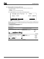
5.1. Cooling profile : the "Cooling profile" menu
A cooling profile is made up of several stages. Each stage is defined by the following elements:
• A type (not modifiable on the device).
• A Set point.
• A condition for passage to the next stage.
Only the stages that have already been programmed may be modified. To personalize the profiles, it is necessary to
go the PC software.
After the Cooling Profile menu has been activated, the following display appears:
Cooling profile No: 1
Name: CFPP
OK
Unit:°C
Details
Next
Figure 33 : Cooling profile menu Display 1
With this display, a cooling profile can be chosen from among the five pre-installed, by activating the Next button as
often as necessary and validating with OK (having received the necessary authorization). On the following displays
the parameters for each profile stage can be seen. Taking as examples two profiles:
1. Cooling profile for the standard CFPP test.
2. Cooling profile for the Simul (°C) test
Cooling profile N°1
Displays
Meaning of different menus
(Cooling Profile menu (No:1).
(Going from left to right and from top to bottom).
Cooling Profile No: 1
CFPP
°C
Name
Cooling Profile menu Display 1 (No :1)
The cooling profile is number 1
(permanent field).
Name : selection of profile name.
Unit : selection of temperature measurement
unit.
Field values
String
°C/°F
Unit
Next display
Cooling Profile No:
1
Step: 1
for
Sample Preheating
at 45.0°C
0 min
Set point
Limit
Cooling Profile menu Display 2 (No :1)
Step 1
Pre-heating of sample.
Set point : Sample pre-heating temperature
setting.
Limit : duration of pre-heating expressed in
minutes, once the setting has been reached.
0 min indicates that there is no pre-heating.
Min +30°C
Max+50°C
Min 0 min
Max 60 min
Next display
Step 1
Tests : there can be no suction during the preheating stage.
Cooling Profile No: 1
Step: 1
No
No
Tests
Cooling Profile menu Display 3 (No :1)
Next display
Cooling Profile No:
1
Step: 2
Jacket level
Until sample
at -34.0°C
< -20.0°C
Set point
Limit
Cooling Profile menu Display 4 (No :1)
Step 2
First cooling stage in the CFPP test
Set point : temperature setting of the jacket
cooling stage.
Limit : limit sample temperature for moving to
next stage of jacket cooling.
Next display
Page 2-48
FPP 5G & 5Gs User Manual
DOCV211A001-D
Advanced use of the FPP 5G/5Gs
Cooling Profile No:
Step 2
Tests : suction (or not) during the first jacket
cooling stage.
Frequency : setting of interval between two
suctions. Intervals are expressed either in
minutes or in degrees °C/°F :
1) Interval in minutes.
1
Step: 2
Temp. Interval
Yes
1.0°C
Tests
Frequency
Cooling Profile menu Display 5 (No :1)
Yes/No
If Tests = Yes:
Min 2 min
Max 60 min
Min 1°C/2°F
2) Interval in °C/°F.
Max 5°C/10°F
The above display is followed by four displays which correspond to the two jacket cooling stages described in standard NF EN 116 :
Step 5
Cooling Profile No:
1
Min 20°C/68°F
Type : 1 - Final jacket re-heating.
Max 30°C/86°F
2 - Preparation of jacket for next test.
Step: 5
Set point : Jacket temperature setting for final
Final Jacket temperature
Heating
25.0°C
re-heating (if Type = 1) or preparation for a new
test (if Type = 2).
Tests
Setpoint
Cooling Profile menu Display 10 (No :5)
Next display
Stage 6
Cooling Profile No: 1
End of profile display - common to all the
profiles.
Step: 6
End of profile
Cooling Profile menu Display 11 (No :1)
Table4: Cooling profile N°1.
Cooling profile N°2
Displays
Meaning of different menus
(Cooling Profile menu No:2).
(Going from left to right and from top to bottom).
Cooling Profile No: 2
Simul
°C
Name
Cooling Profile menu Display 1 (No :2)
Field values
Cooling profile 2
Name : selection of profile name.
Unit : selection of temperature measurement
unit.
Unit
Next display
Cooling Profile No:
2
Step: 1
Jacket Cooling
Until sample
rate at 40.0°C/h
< -70.0°C
Set point
Limit
Cooling Profile menu Display 2 (No :2)
Stage 1
Sample cooling rate
Set point : setting of jacket cooling rate.
Limit : limit sample temperature for moving to
next stage.
Min 0.5°C/h-1°F/h
Max
60°C/h-108°F/h
Next display
Cooling Profile No:
2
Step: 1
Temp. Interval
Yes
1.0°C
Tests
Frequency
Cooling Profile menu Display 5 (No :2)
Cooling Profile No:
2
Step: 2
Final
Jacket Temperature
Heating
25.0°C
Type
Set point
Cooling Profile menu Display 5 (No :2)
Stage 2
Tests : suction
Frequency : setting of interval between two
suctions. Intervals are expressed either in
minutes or in degrees °C/°F :
1) Interval in minutes.
2) Interval in °C/°F.
Yes/No
If Tests = Yes:
Min 2 min
Max 60 min
Min 1°C/2°F
Max 5°C/10°F
Next display
Stage 3
See Cooling Profile menu Display 10 (No :1)
End of profile.
Table 5: Cooling profile N°2
DOCV211A001-D
FPP 5G & 5Gs User Manual
Page 2-49
FPP 5G & FPP 5Gs
5.2. Vacuum profile: the "Vacuum profile" menu
A vacuum profile is composed of segments. Each segment is defined by the following elements:
• A type (non modifiable).
• A setting.
• A condition for moving to the next stage (if necessary).
After the Vacuum Profile menu has been activated, the following display appears:
Vacuum profile No:
Name: CFPP
OK
1
CFPP
Unit: mmH2O
Details
Next
Figure 34 : Vacuum Profile menu Display 1
This display allows one of the two pre-installed vacuum profiles to be chosen, by activation of the Next button and
validation with OK (the necessary authorization having been received). The following displays show the parameters
for each stage of the profiles:
1. Vacuum profile for the standardized CFPP test
2. Vacuum profile for the Simul (°C) test
Vacuum profile N°1
Displays
Meaning of different menus
(Vacuum Profile menu).
(Going from left to right and from top to bottom).
Vacuum profile No: 1
CFPP
CFPP
mmH2O
Name
Vacuum Profile menu Display 1.
Unit
Vacuum profile N°1 CFPP (perm. field)
Name : profile name.
Unit : unit of vacuum measurement.
Field values
Charac.
mmH2O
KPa
mbar
Next display
Vacuum profile No: 1
Segment: 1
CFPP
Segment 1
Constant Vacuum
Set pt : setting of vacuum value.
Constant
200 mmH2O
Set pt
Vacuum Profile menu Display 2.
(150 250)
mmH2O
(1.5 2.5)
Kpa
(15.0 25.0)
mbar
End of profile
Table 6: Vacuum profile displays N°1
Page 2-50
FPP 5G & 5Gs User Manual
DOCV211A001-D
Advanced use of the FPP 5G/5Gs
Vacuum profile N°2
Displays
Meaning of different menus
(Vacuum Profile menu).
(Going from left to right and from top to bottom).
Vacuum profile No: 2
Simul
Name
Vacuum Profile menu Display 1.
Simul
Vacuum profile N°2 Simul (perm. field)
Name : name of profile.
Unit : unit of vacuum measurement.
KPa
Unit
Field values
String
mmH2O
Kpa
mbar
Next display
Vacuum profile No: 2
Simul
Segment: 1
Segment 1
Linear variation vacuum
Set pt : First vacuum limit value.
Linear
9.00 KPa
10 s
Set pt to be reached in
Vacuum Profile menu Display 2.
to be reached in : time, in seconds, before
moving to second vacuum limit value.
The display above is followed by two displays corresponding to segment 2 and segment 3 of the vacuum profile:
1. 13,50 KPa to be attained in 26s
2. 15,50 KPa to be attained in 60s
End of profile
Table7: Vacuum profile displays N°2
DOCV211A001-D
FPP 5G & 5Gs User Manual
(0 1600)
mmH2O
(0 16)Kpa
(0 160)mbar
(1 180)s
Page 2-51
FPP 5G & FPP 5Gs
6. Measurement and diagnostics: the "Service" menu
FPP 5G
S/N: 212
Software V 2.4/ 2.4 (C) ISL, 1999
FPP Run
Start
Display
Results
FPP 5G
S/N: 212
Software V 2.4/ 2.4 (C) ISL, 1999
⊕
Access
Print
Program
Service
FPP 5G
S/N: 212
Software V 2.4/ 2.4 (C) ISL, 1999
Quality
Setup
Clean.
Service
Service
Measure
Diagnostics
Diagram 6 : The Service menu.
The Service menu is in great part dedicated to maintenance. With this menu it is possible to:
• Display measures.
• Slave the main parts of the device.
Activating the Service menu calls up the following display:
Service
Measures
Diagnostics
Figure 35: Service menu displays.
The Measurements and Diagnostics menus lead to a series of screens. The series of screens for the FPP 5G
differs from those for the FPP 5Gs. In fact, on the FPP 5Gs the menus allow a built-in cooling compressor diagnostic
to be made if necessary.
6.1. Measurement and diagnostic on the FPP 5G analyzer
The Measures menu (in the Service menu) gives access to the following information, organized into three displays:
Displays
Meaning of different menus
(Measures menu).
(Going from left to right and from top to bottom).
Samp.:
Jack.:
Refr.:
A/D:DEDE
30.4°C 111.85Ω
A/D:BE17
29.2°C 111.38Ω
31 °C
Cool.:
0.0%
Heat.:
0 0%Print
Measures menu Display 1.
Sample, jacket, and refrigerant temperatures taken.
Field values
Samp. : sample temperature (°C).
resistance of sample probe.(Ω).
Jack. : jacket temperature (°C)
resistance of jacket probe. (Ω).
A/D : analog/digital conversion.
Refr. : cooling circuit entry temperature.
Cool. : percentage cooling.
Heat : percentage heating.
Print : printing of three displays.
Next display
Pressure:
Pump
:
1 mmH2O
0 mmH2O
A/D:
D/A:
F97
0
Print
Measures menu Display 2.
Pressure measured and pump command noted.
Pressure : measured depression value.
A/D : analog/digital conversion.
Pump : vacuum value imposed on pump.
D/A : digital/analog conversion.
Print : printing of three displays.
Next display
Page 2-52
FPP 5G & 5Gs User Manual
DOCV211A001-D
Advanced use of the FPP 5G/5Gs
Upper opt. det.
Lower opt. det.
Receiver:
0pts
Receiver:
0pts
Emitter :
0pts
Emitter :
0pts
Print
Measures menu Display 3.
Optical sensors reading noted.
Upper optical detector.
Receiver : number of points received.
Emitter : number of points emitted.
Lower optical detector.
Receiver : number of points received.
Emitter : number of points emitted.
Table8: Measures menu displays.
The Diagnostics menu can be accessed with the level 2 access authorization (maintenance).
Displays
Meaning of different menus
(Diagnostics menu).
(Going from left to right and from top to bottom).
Samp.:30.4°C
111.85 Ω
A/D:DEDE
A/D:BE17
Jack.:29.2°C
111.38 Ω
Refr.: 31 °C
0.0%
0.0%
Cool.
Heat.
Diagnostics menu Display 1.
Field values
For upper part of display, see Table8.
Cool. : percentage of cooling entry.
Heat.: percentage of heating entry.
Next display
AirSV
200 / 1600
mmH2O
(2 / 16) Kpa
(20 / 160)
mbar
Diag. = 200 mmH2O ; Pump = ON
Suct.SV = ON/OFF
AirSV = OFF
Pump : manual pump start.
ON/OFF
Suct.SV : open/shut suction solenoid valve
ON/OFF
AirSV : open/shut leak solenoid valve.
ON/OFF
Diag. = 1600 mmH2O ; Pump = ON
Suct.SV = ON or OFF (set before pump start )
AirSV = ON
For upper part of display, see Table8.
Pressure:
Pump
:
1 mmH2O
0 mmH2O
200 mmH20 OFF
A/D:
D/A:
F97
0
OFF
Diag
Pump
Suct.SV
Diagnostics menu Display 2
OFF
Diag. : vacuum setting.
Next display
Upper opt. det.
Receiver:
0pts
Emitter :
0pts
Auto.
Emit
Diagnostics menu Display 3
Lower opt.det.
Receiver:
0pts
Emitter :
0pts
Auto.
Emit
Optical detector
Emitter : number of points emitted.
0 pts : no light emitted.
4095 pts : maximum light emitted
Receiver : number of points received :
0 pts : no light received.
4095 pts : maximum light received.
Auto. : automatic control of emitter to obtain a
given no. of points on the receiver (≈2000 pts).
Emit : manual entry of number of points to be
emitted.
0 4095 pts
(max. emission)
0
4095 pts
Table 9: Diagnostics menu displays.
DOCV211A001-D
FPP 5G & 5Gs User Manual
Page 2-53
FPP 5G & FPP 5Gs
6.2. Measurement and diagnostic on the FPP 5Gs analyzer
The Measures menu (in the Service menu) gives access to the following information, organized into three displays:
Displays
Meaning of different menus
(Measures menu).
(Going from left to right and from top to bottom).
Samp.: 22.7°C
Jack.: 27.9°C
108.84Ω
110.86Ω
A/D:D8DE
A/D:BD33
Cooling unit: 0
Heat.:
0
00000001
0.0%
0.0%
Print
Measures menu Display 1.
Sample, jacket, and refrigerant temperatures taken.
Samp. : sample temperature (°C).
resistance of sample probe.(Ω).
Jack. : jacket temperature (°C)
resistance of jacket probe. (Ω).
A/D : analog/digital conversion.
Cooling unit:
- Effective number of applied points. Information given back by the
cooling compressor command board.
D0 : reserved for ISL use
D1 : reserved for ISL use
D2 : reserved for ISL use
D3 : ventilation 1 = ON / 0 = OFF
D4 : temperature alarm
D5 : optical stroke
D6 : maximum current
D7 : optical stroke fault
- Request in percentage sent to the cooling compressor control
board.
Heat. :
- Effective number of applied points. Information given back by the
cooling compressor command board.
- Request in percentage sent to the cooling compressor control
board.
Pressure:
Pump
:
1 mmH2O
0 mmH2O
A/D:
D/A:
F97
0
Print
Measures menu Display 2.
Pressure measured and pump command noted.
Upper opt. det.
Lower opt. det.
Receiver:
0pts
Receiver:
0pts
Emitter :
0pts
Emitter :
0pts
Print
Measures menu Display 3.
Optical sensors reading noted.
Print : printing of three displays.
Next display
Pressure : measured depression value.
A/D : analog/digital conversion.
Pump : vacuum value imposed on pump.
D/A : digital/analog conversion.
Print : printing of three displays.
Next display
Upper optical detector.
Receiver : number of points received.
Emitter : number of points emitted.
Lower optical detector.
Receiver : number of points received.
Emitter : number of points emitted.
Table 10: Measures menu displays.
Page 2-54
FPP 5G & 5Gs User Manual
DOCV211A001-D
Advanced use of the FPP 5G/5Gs
The Diagnostics menu can be accessed with the level 2 access authorization (maintenance).
Displays
Meaning of different menus
(Diagnostics menu).
(Going from left to right and from top to bottom).
Samp.: 22.7°C
Jack.: 27.7°C
108.84Ω
110.77Ω
Cooling unit : 0
00000001
0.0
C.Unit
Cool.
Diagnostics menu Display 1.
A/D:D8DE
A/D:BD33
Heat.:
0
0.0
Heat.
Field values
For upper part of display, see Table 10.
C. Unit: enables to start cooling unit diagnostic.
Cool. : enables entering a percentage of cooling
Heat.: enables entering a percentage of heating.
Next display
For upper part of display, see Table 10.
Pressure:
1 mmH2O
A/D:
F97
Pump
:
0 mmH2O
D/A:
0
200 mmH20 OFF
OFF
OFF
Diag
Pump
Suct.SV AirSV
Diagnostics menu Display 2.
Diag. : vacuum setting
Pump : manual pump start.
Suct.SV : open/shut suction solenoid valve
AirSV : open/shut leak solenoid valve.
Diag. = 200 mmH2O ; Pump = ON
Suct.SV = ON/OFF
AirSV = OFF
200 / 1600
mmH2O
(2 / 16) Kpa
(20 / 160) mbar
ON/OFF
ON/OFF
ON/OFF
Diag. = 1600 mmH2O ; Pump = ON
Suct.SV = ON or OFF (set before pump start )
AirSV = ON
Next display
Upper opt. det.
Receiver:
0pts
Emitter :
0pts
Auto.
Emit
Diagnostics menu Display 3.
Lower opt.det.
Receiver:
0pts
Emitter :
0pts
Auto.
Emit
Optical detector.
Emitter : number of points emitted.
0 pts : no light emitted.
4095 pts : maximum light emitted
Receiver : number of points received :
0 pts : no light received.
4095 pts : maximum light received.
Auto. : automatic control of emitter to obtain a
given no. of points on the receiver (≈2000 pts).
Emit : manual entry of number of points to be
emitted.
0 4095 pts
(max. emission)
0
4095 pts
Table11: Diagnostics menu displays.
Activating the C. Unit menu (first screen of the Diagnostic menu) gives the possibility of running the diagnostic
procedure for a built-in cooling compressor.
Before running diagnostics remove pipette, tube and basket and place the cover on the jacket .
The diagnostic procedures may run for up to 80 minutes.
Diagnostics has three phases:
1.Initialization: heating to 40°C and regulation for 3 min.
2.Cooling: cooling to –110°C. During this phase the values of temperatures to be noted are taken (time required
to fall to each notable temperature and effective number of points at this same temperature).
3.Reheating: return to ambient temperature.
The Print button allows a print-out to be made of the cooling compressor parameters (plus the values noted during
phase two – see above) which can, if necessary, be sent to ISL’s Customer Service for the compressor’s condition to
be checked.
The following table explains the cooling unit diagnostic procedure to follow:
DOCV211A001-D
FPP 5G & 5Gs User Manual
Page 2-55
FPP 5G & FPP 5Gs
Displays
Meaning of different menus
(C. Unit menu).
(Going from left to right and from top to bottom).
Cooling unit diagnostic
Remove pipette, tube and basket
Place cover on jacket, then press start
100%
(Duration: 80 min max)
Cool.
Start.
Print
C. Unit menu Display 1.
Cooling unit diagnostic
Samp. : 39.9°C
Time :1min02s
Cooling unit : 80
Heat.: 36
00001001
10.0%
14.1%
Stop
< Current step>
C. Unit menu Display 2.
Cooling unit diagnostic
Samp. : 25.0°C
Time : 15min 32s
Cooling unit: 80
Heat.: 36
00001001 10.0%
14.1%
Print
Exit
Diagnostic completed
C. Unit menu Display 3.
Cool.: button for entering percentage cooling required (100% by
default)
Start: menu for running the diagnostic procedure.
Print : printing cooling compressor parameters stored during the last
diagnostic.
Next display
Samp.: sampling temperature
Time: elapsed time. Three-minute countdown during the initialization
phase, then diagnostic phase countdown.
Cooling unit:
- Effective number of applied points. Information given back by
the compressor control board.
- D7 to D0 see Table 10.
- Request in percentage sent to the compressor control board.
Heat.:
- Effective number of applied points. Information given back by
the compressor control board.
- Request in percentage sent to the compressor control board.
Stop: stop the diagnostic procedure and return to the first display of
the C. Unit menu.
<Current step> : one of the three following steps:
- Initialization,
- Cooling,
- Reheating.
Next display
Upper part similar to previous display.
Print : cooling compressor parameters.
Exit: back to first displays of the C. Unit menu.
Table12: C. Unit menu displays.
Page 2-56
FPP 5G & 5Gs User Manual
DOCV211A001-D
Advanced use of the FPP 5G/5Gs
7. Adjustment and calibration: the "Quality" menu
FPP 5G
S/N: 212
Software V 2.4/ 2.4 (C) ISL, 1999
FPP Run
Start Display
Results
FPP 5G
S/N: 212
Software V 2.4/ 2.4 (C) ISL, 1999
⊕
Access
Print
Program
Service
FPP 5G
S/N: 212
Software V 2.4/ 2.4 (C) ISL, 1999
Quality
Setup
Clean.
Quality
Quality
Correct
Table
Quality
Samp.T.
Calib
Jack.T.
Calib.
Vacuum
Calib.
Calib. ticket
Printing
Diagram 7 : The Quality menu
The FPP 5G measurement instrumentation sometimes requires calibration. How often depends on the user, but it is
recommended that all the measurement instruments be adjusted at least once a year. The Quality menu has a
series of menus dealing with the following adjustments; these are grouped in the display below:
Quality
Correct Samp.T. Jack.T.
Table
Calib
Calib.
Vacuum
Calib.
Figure 36: Quality menu display 1
• The "Correct Table" menu: sample temperature measurement correction table.
• The "Samp. T. Calib" menu: calibration of sample temperature measurement. .
• The "Jack. T Calib" menu: calibration of jacket temperature measurement. .
• The "Vaccum Calib" menu: vacuum circuit calibration.
Adjustments carried out in this way can be printed out using the Calib. ticket Printing : menu
Quality
Calib. ticket
Printing
Figure 37: Quality menu display 2
DOCV211A001-D
FPP 5G & 5Gs User Manual
Page 2-57
FPP 5G & FPP 5Gs
7.1. Sample probe correction table: the "Correct Table" menu
The Correct Table menu makes it possible to enter a correction table for the sample temperature measurement
probe. The sample temperature displayed takes this table into account (at rest, during testing and during calibration).
The sample probe is a Pt100 platinum probe compliant with standard IEC 51 - Class A. It is
supplied with an ISL Quality Certificate stating the value of the temperature discrepancy at 40°C
(discrepancy = (Value – reference t°)°C).
On activating the Correct Table menu the following display appears:
Sample probe correction table
Correction: (Probe value - reference)
°C
Name
Unit
Figure 38: Correct Table menu Display 1
This display allows the name of the correction table to be entered and the table’s unit of temperature to be selected.
On a series of displays similar to the display below the correction values can be entered (correction value = value
indicated by the probe – reference value), for temperatures from -100°C (-148°F) to +90°C(194°F) (with an increment
of 10°C) :
Sample probe correction table
Correction: (Probe value - reference)
0.0
0.0
0.0
0.0
-100°C
-90°C
-80°C
-70°C
Figure 39: Correct Table menu Display 2(/ 5): correction value entry display.
7.2. Calibration of sample temperature measurement : the "Samp. T. Calib." menu
Calibration of the sample temperature measurement is done through the Samp.T. Calib. menu. The sample
temperature measurement must be calibrated using the following procedure:
Procedure :
1.
2.
3.
4.
Page 2-58
Remove the DIN plug fom the probe.
Insert, into the free probe socket, the probe simulator socket (see spare parts list).
Activate the Samp. T. Calib. menu
Follow the indications on the displays set out below:
FPP 5G & 5Gs User Manual
DOCV211A001-D
Advanced use of the FPP 5G/5Gs
Displays
Meaning of different menus
(Samp. T. Calib. menu).
(Going from left to right and from top to bottom).
Sample temp. measurement calibration
Performed:01/01/1999 Next:O1/01/2000
365 days
NO
Frequency
Test refusal
Samp. T. Calib. menu Display 1
Field values
Frequency : frequency of calibration.
0 days indicates that there is no check for
the passing of the calibration date
Test refusal : initiation of test denied when
date set for calibration passed.
0
365 days
Operator : name of calibration operator.
Calib. Reference : calibration reference.
String
String
Yes/No
Next display
Sample temp. measurement calibration
<Name>
<Ref.>
operator
Calib.Reference
Samp. T. Calib. menu Display 2
Next display
Cancel : cancel calibration; Return to display 1 of « Samp. T. Calib »
menu.
Continue : once calibration has been initiated it is no longer possible
to cancel it . The keys on the front panel are disabled.
Sample temp. measurement calibration
CAUTION: be sure the Pt100 simulator
is connected, then press (continue).
Cancel
Samp. T. Calib. menu Display 3
Continue
Sample temp. measurement calibration
Position simulator on -50°C/-58°F
80.310 Ω
⊕
Resistor value
Next display
Position the simulator knob at
-50°C/-58°F.
Resistor value : enter, if necessary, the resistance value (Ohm).
Samp. T. Calib. menu Display 4
Sample temp. measurement calibration
Samp.: -50.0°C
80.310 Ω
A/D:88D9
Press (OK) when the reading is stable.
Ok
Samp. T. Calib. menu Display 5
Next display
When the display becomes almost stable (with the first thre
characters of the A/D conversion stable) validate withOK.
Proceed similarly with the simulator knob set on +50°C/122°F.
At the end of operation display1 of the Quality is displayed.
Table13: Samp. T. Calib. menu displays
DOCV211A001-D
FPP 5G & 5Gs User Manual
Page 2-59
FPP 5G & FPP 5Gs
7.3. Calibration of jacket temperature measurement: the "Jack. T Calib." menu
Jacket temperature measurement calibration should preferably be carried out after calibration of the sample probe
(see preceding paragraph). Calibration of the jacket temperature measurement can be carried out in one of two ways:
1. Automatically, by means of the sample probe.
2. Manually, by means of a calibrated thermometer.
The FPP 5G/s calculates the difference between the temperature indicated by the sample probe and the jacket
temperature. If this is too big, it will consider that the calibration is being done by means of the external calibrated
thermometer. In this case it will wait for a reference value to be entered before moving from one stage to the next.
Procedure :
1. Follow the indications on the displays set out in the following table:
Displays
Meaning of different menus
(Jack. T. Calib. menu).
(From left to right and from top to bottom).
Jacket temp. measurement calibration
<Name>
Operator : name of the operator for the jacket temperature probe
calibration.
Calib. Reference : calibration reference.
<Ref.>
Operator
Calib.Reference
Jack. T. Calib. menu Display 1
Jacket temp. measurement calibration
Fill the jacket up to the mark and
immerse the reference probe.
Setpt:10/-34°C
Jack. T. Calib. menu Display 2
Continue
Next display
Fill the jacket up to the mark visible on the internal wall of the jacket,
with the same liquid as that used in the cooling circuit.
Selection of two setting temperatures
Setpt: 10/-34°C or
Setpt: -34/51°C : cooling stages.
Continue : continuance of operation.
Next display
Jacket temp. measurement calibration
Set point : 10.0°C Waiting
:6 min
Jacket
: 29.8°C Sample
:29.0°C
Cancel
Jack. T. Calib. menu Display 3
Jacket temp. measurement calibration
Jacket
: 10.0°C Sample
:10.0°C
Waiting : 10 min
°C
Cancel
Jack. T. Calib. menu Display 4
Reference
Set point : selection of the two calibration points.
Waiting : waiting time for cooling of jacket
Jacket : jacket temperature.
Sample : sample temperature.
Cancel : ending of calibration procedure
(the only way of stopping the operation).
Next display
Jacket : jacket temperature.
Sample : sample temperature.
Waiting : waiting time for stabilization of sample temperature. During
this time the operator can enter the reference value (reference field). If
the sample probe is used, the FPP 5G/s will automatically take the
value of the sample temperature shown on the screen.
Cancel : stopping of calibration.
Reference : sample temperature :
-read on the thermometer.
-or measured by the probe.
Do the same for the second stage (-34.0°C).
End of jacket temperature calibration.
wait until the jacket is reheated
before draining it.
Jacket: 15°C
OK
At the end of the operation the FPP 5G/s reheats the jacket to +25°C
so as to allow emptying.
Jack. T. Calib. menu Display 5
Table14: Jack. T. Calib.menu displays
Page 2-60
FPP 5G & 5Gs User Manual
DOCV211A001-D
Advanced use of the FPP 5G/5Gs
7.4. Calibration of vacuum circuit: the "Vacuum Calib." menu
Vacuum pump calibration can be carried out at two vacuum levels : 200 mmH2Oand 1600 mmH2O.
For this calibration a manometer able to measure 250 mmH20 for the first level and 2000mmH20 for the second is
needed.
Note: Only the vacuum level of the pump can be calibrated. The air flow rate in the pump is
enslaved according to the vacuum.
The vacuum profile is managed by the system.
Procedure :
Displays
Meaning of different menus
(Vacuum Calib. menu).
(Going from left to right and from top to bottom).
Vacuum measure calibration
mmH2O
Exit
200
1600
Vacuum Calib. menu Display 1
Vacuum calibration
Exit : operation cancel.
200 mmH2O
1600 mmH2O
Unit :
Unit
Vacuum meas.calibration at
<Name>
200 mmH2O
Vacuum calibration at 200 mmH2O
Operator : operator name
Calib Reference : calibration reference.
Field values
KPa
mmH2O
mbar
Next display
String
String
<Ref.>
Operator
Calib.Reference
Vacuum Calib. menu Display 2
Next display
Vacuum meas.calibration at 200 mmH2O
Connect a manometer able to measure
250 mmH2O then press (OK).
Ok
Vacuum Calib. menu Display 3
At the end of the vacuum tube attach a
manometer able to measure 2.50 KPa.
Validate by activating the OK button
Next display
Vacuum meas.calibration at
Calibration at 0 mmH2O
200 mmH2O
Presetup at 0 KPa : resetting of A/D converter
waiting : time necessary for resetting.
waiting : 12s
Vacuum Calib. menu Display 4
Vacuum meas.calibration at 200 mmH2O
Wait for circuit depressure : 10 s
Cancel
Vacuum Calib. menu Display 5
Wait for circuit depressure : time necessary to
attain vacuum level desired (2.00 or 16.00)KPa.
Cancel : stops calibration.
Next display
10s
200mmH2O
30s
1600mmH2O
Cancel
Next display
OK : validates calibration.
Set pt : entry of value read on manometer.
-/+ : adjustment of vacuum as read on reference
manometer.
Ajust the depressure with -/+
or enter the read value.
200 H2O
D/A: 2E0
OK
Set pt
-
+
Vacuum Calib. menu Display 6
Table 15: Vacuum Calib. menu displays
DOCV211A001-D
FPP 5G & 5Gs User Manual
Page 2-61
FPP 5G & FPP 5Gs
7.5. Jacket temperature checking procedure
To access to the jacket temperature checking procedure, press the “Jack T. check” button of the Quality menu (see
second screen, Diagram 7 page 2-57 ).
Procédure:
Displays
Meaning of different menus
(Jacket temperature checking menu).
(Going from left to right and from top to bottom).
Jacket temperature checking
Fill the jacket up to the mark and
Immerse the reference probe
Jacket temperature checking: permanent field
Continue : fill the jacket with methanol, position the probe inside then
press the Continue key to go on.
Continue
Jacket Temperature checking Display 1
Next screen
Jacket temperature checking: permanent field
Jacket Set point : enter a set-point temperature for the jacket. Press
the Enter key on the keyboard to validate.
Start : Start the jacket temperature checking procedure
Jacket temperature checking
Jacket Set Point
Jacket Temperature checking Display 2
Start
Next screen
Jacket temperature checking: permanent field
Jacket : jacket temperature measured by the analyzer
Jacket temperature checking
Sample: sample temperature measured by the sample temperature
Jacket:22,2°C
Sample.:21,9°C
probe
Set point : -34°C
Waiting : min
Set point : jacket set point temperature
Abandon
Waiting : near the set point temperature (0,25°C or 0,45°F), a
countdown is activated before the temperature is stable
Jacket Temperature checking Display 3
15 mn after the set point temperature is reached, the analyzer displays the jacket temperature and the temperature read by the
sample temperature probe. These ones must be similar. Perform a jacket temperature calibration if necessary (see section Part
01.1 of this part, page 2-60).
Next screen
Jacket temperature checking: permanent field
Jacket temperature checking
At the end of the checking procedure the FPP 5G/s reheats the
Wait for the jacket reheating
jacket up to +25°C to allow to drain the jacket
Before draining it
OK : validate the procedure and return to the Quality menu
Jacket : 15°C
OK
Jacket Temperature checking Display 4
Table 16: Jacket temperature checking menu displays
Page 2-62
FPP 5G & 5Gs User Manual
DOCV211A001-D
Advanced use of the FPP 5G/5Gs
8. Alarm treatment
8.1.Types of alarm
8.1.1. Failure alarms
The failure alarms warn the operator in the event of a malfunction.
Failure alarm detection has at least one of the following consequences:
• A test cannot be started,
• A test in progress is stopped,
These failures set off a continuous audio alarm and the red LED of the ALARM STOP key lights up on the keypad (see
the section 6.1.3 page 21). Press the ALARM STOP key to display the alarm message and acknowledge it or not. The
red LED stays on for as long as the failure persists, even if the alarm has been acknowledged.
The failure alarms and the corresponding message are shown in the section 9.4.2 page 2-67.
The limits of certain of these failure alarms can be set (refer to the section 9.3 - Configuring alarms: the "Alarm" menu
page 2-66).
8.1.2. Warning alarms
The warning alarms warn the operator of an expected event: “ End of test with CFPP ” for example.
They are accompanied as for them by a discontinuous audio alarm (the signal modulation width is adjustable; refer to
the section 9.3 - Configuring alarms: the "Alarm" menu page 2-66). The red LED on the ALARM STOP key lights up on
the keypad. It goes off when the alarm is acknowledged.
The warning alarms and the corresponding message are shown in the section 9.4.3 page 2-69.
8.2.Displaying alarms, stopping the buzzer
When an alarm is triggered, press the ALARM STOP key to display the cause. The following screen is displayed:
No alarm to signal
Exit
Acquit
Review
Figure 40: Alarms displaying screen
The alarms screen display contains the following menus and buttons:
Exit: to go back to the previous screen without acquitting the alarm.
Acquit.: to acquit the alarm and to go back to the previous screen.
Press the Acquit key to stop the buzzer and return to the previous screen. Note that the red LED on the ALARM
STOP key stays on for as long as the default persists, even if the alarm has been acknowledged.
Review: to display the alarm historical.
8.3. Alarm processing
Certain alarm cases present a danger. This is why most default settings switch the Analyzer into idle status, thus the
cooling unit is cut out and the heating is stopped.
However, this is not to say that this type of analyzer is hazard-free or that if the Analyzer fails to go into idle status the
operator and/or Analyzer are not in danger. It is important always to check what is going on whenever an alarm is
triggered.
Attention! Generally when the alarm buzzer is triggered, the operator must display the cause and
ensure that everything is working correctly.
For example, owing to a faulty component an alarm that normally should place the analyzer in idle mode fails to do
so. In that case, the operator must intervene by switching off the Analyzer.
DOCV211A001-D
FPP 5G & 5Gs User Manual
Page 2-63
FPP 5G & FPP 5Gs
8.4. Alarms historical
The FPP 5G/s can register up to 16 alarm messages.
Activate the Review menu from the alarm displaying screen (see Figure 40 page 2-63), the following screens appear:
Displays
Meaning of different menus
(Review menu of the Alarm displaying screen)
(Going from left to right and from top to bottom).
Faults review
Date
Time
Message registered
Exit
Print
Field values
Faults review : permanent field
Exit: To go back to the alarms displaying screen
Print: To print the complete alarms review
Details: To display the detailed alarm message
Details
Display 1 of the Review menu
Press the Details key to access to the detail displaying screen of the alarm selected:
Date:
Src:
Def:
Exit
Details display the Review menu
Next Display
Date: date at which the failure occurs
Src: state of the analyzer when the alarm occurs Status: Idle,
Running, Jacket
Def: alarm message displayed
preparation,
Cleaning,
Diagnostic
Exit: to go back to the alarm displaying screen
Table 17: Screens of Review menu of the alarms displaying screen
Page 2-64
FPP 5G & 5Gs User Manual
DOCV211A001-D
Advanced use of the FPP 5G/5Gs
9. Configuration: the "Setup" menu
FPP 5G
S/N: 212
Software V 2.4/ 2.4 (C) ISL, 1999
FPP Run
Start
Display
Results
⊕
Access
FPP 5G
S/N: 212
Software V 2.4/ 2.4 (C) ISL, 1999
Print
Program
Service
FPP 5G
S/N: 212
Software V 2.4/ 2.4 (C) ISL, 1999
Quality
Setup
Clean.
Setup
FPP 5G
Analyser setup
Pwr.on
S/N: 212
FPP 5G
S/N: 212
Analyser setup
Display
Alarms
Labo
Printer
RS232
FPP 5G
S/N: 212
Analyser setup
PC Link
Clock
Service
ISL
Diagram 8 : Setup menu
The FPP G5/s "working environment" can be completely configured. Thus the testing and cleaning programs in place
when the device is switched on can be re-set. The triggering or stopping of an alarm can also be set for when a given
error occurs and in other conditions set out below.
The configuration of the FPP 5G/s is carried out by means of the Setup menu at the main display level (see Figure
23 on page 2-38). After the Setup menu is activated the following display appears :
FPP 5G
Analyser setup
Pwr.on
Display
S/N: 212
Alarms
FPP 5G
Analyser setup
Printer
RS232
S/N: 212
PC Link
FPP 5G
Analyser setup
Service
Labo
Clock
S/N: 212
ISL
Figure 41: Setup menu displays.
The above displays allows access to the configuration parameters set out below.
DOCV211A001-D
FPP 5G & 5Gs User Manual
Page 2-65
FPP 5G & FPP 5Gs
9.1. Power on parameters: the "Pwr.on" menu
The Power on parameters menu allows choice of the test program, the cleaning program and the access level in
place when the device is switched on.
Displays
Meaning of different menus
(Power on parameters. menu).
(Going from left to right and from top to bottom).
Power on parameters
Program : Test program choice.
Cleaning : Cleaning program choice.
Power on parameters
1: CFPP (°C)
Program
Field values
1
1
5
2
1:
Cleaning
Display 1 of the Pwr. on menu
Access level : choice of default access level
when the device is switched on.
: It should be noted that only the current
access level or lower access level can be
chosen.
Power on parameters
0
Selection
2
Access Country
Auto
level
Langua Edition
Country language: choice of language
selected by default (locked). “Selection” allows
the operator to choose the language.
Auto Edition : characters number needed to
activate the auto edition (0 inhibits the function).
Display 2 of the Pwr. on menu
Next display
0, 1 or 2
Selection/English/
Français
0
9
Table 18: Power on parameters menu displays.
9.2. Configuring results display: the "Display" menu
Up and Down times, and temp. H can be displayed/printed in seconds or in tenths of seconds. Example :
Format 99 seconds time in seconds.
99.9 seconds time in tenths of a second.
A tenths of a second display is only possible with results obtained with version 1.5 of the control software and
displayed in the Results Menu.
If the time is greater than 99.9 seconds, the display automatically switches to seconds.
A test which is running will always be displayed in seconds.
9.3. Configuring alarms: the "Alarm" menu
With this menu an audible alarm can be activated or de-activated for a given fault or indication. Activation of this menu
calls up the following display:
Alarms set up
Buzzer
ON
On/Off
20%
Modulation
Test
Figure 42: Alarms menu Display 1
With this menu the alarm can be activated or de-activated as a warning system, without, however, preventing the
LED of the ALARM STOP lighting up. Reminder: pressing on this button reveals the error message content.
The intermittence of discontinuous alarms can be adjusted by means of the Modulation button (100% continuous
alarm - 0% alarm mute).
Warnings, alarms and their corresponding messages are presented as follows:
Page 2-66
FPP 5G & 5Gs User Manual
DOCV211A001-D
Advanced use of the FPP 5G/5Gs
9.4. Faults and indications
9.4.1. Programming
Alarm
Buzzer active = No/OFF => The buzzer is globally inhibited.
Buzzer active = Yes/ON The buzzer will be active or inhibited depending on
the configuration of each active alarm or signal.
Buzzer OFF does not affect the alarm or the red LED but only the buzzer.
Buzzer modulation may be programmed for the signals, from 0% (buzzer off) to 100% (continuous buzz).
9.4.2. Faults
Faults are indicated by the red LED and a permanent buzz.
Releasing stops the buzzer, the LED remains lit as long as the fault is present.
Faults
Memory code fault
Data memory fault
Saved memory fault
Battery fault
Tests and complementary information
Calculation and checksum comparison check made on powering-up.
If this failure is reported, switch the analyzer off then on again. If the failure
persists, contact the ISL Customer Service.
Write, then read, checks made on powering-up.
If this failure is reported, switch the analyzer off then on again. If the failure
persists, contact the ISL Customer Service.
The battery for backing up the non-volatile back-up memory (NVRAM) has
a service life of 7 to 8 years. This alarm may therefore be due to a faulty
battery.
The content of the saved RAM memory where the Analyzer parameters are
stored is checked by the microprocessor. If there is an error, the Analyzer
goes automatically into « download » mode so that the contents of the RAM
memory saved can be restored by loading a backup file from a PC.
For this purpose, a diskette containing the internal parameter factory settings
(necessary if memory has not been recently uploaded) and a PC
up/download program are shipped with the standard version of the
Analyzer. Refer to the section 9.9.4 page 2-73on how to load the Analyzer
parameters.
Note: So as to have an up-to-date copy of the Analyzer’s internal
parameters always to hand, it is advised to upload the internal
parameters to the PC during routine maintenance operations.
Use a new file name each time this operation is performed. Do not use the
internal parameter file name on the original diskette supplied with the
Analyzer.
Permanent check.
The battery is used while the machine is stopped, for the dock and to save
parameters stored in RAM.
If the failure is reported:
Do not switch off the Analyzer as this will delete any stored
data.
Effects
Inhibits testing.
Inhibits testing.
Machine blocked
because loading of
internal parameters
requested.
Print or upload to a PC file the Analyzer parameters contained
in the non-volatile back-up memory, the NVRAM (see the
section 9.9.4 page 2-73).
A/D converter fault
Upper optical fork fault
Lower optical fork fault
DOCV211A001-D
Switch off the Analyzer and call a qualified technician to
replace the battery.
Download Analyzer internal parameters or enter them.
Note: Regular uploading of the internal parameters must be
programmed as part of the analyzer maintenance procedure. Use a
new filename (e.g. with the current date in the name- PIDDMMYY.
NVM). This way the latest version of the internal parameters will be
saved to a file.
Permanent check made for absence of dialogue with converter.
Inhibits testing and stops
a current test.
Check made at the end of light slaving
Stops a current test
(For the TLF, slaving is made before each suction)
Fault condition if transmission is strong and reception is weak, or if
transmission is weak and reception is strong
Thresholds are not programmable
Alarm stopped each time a test is run
Check made at the end of light slaving
Stops a current test
(For the TLF, slaving is made before each suction)
Fault condition if transmission is strong and reception is weak, or if
transmission is weak and reception is strong.
Thresholds are not programmable
Alarm stopped each time a test is run
FPP 5G & 5Gs User Manual
Page 2-67
FPP 5G & FPP 5Gs
Ambient light too
strong
Vacuum circuit fault
Cooling circuit fault
Checking is continuous.
Does not stop a test in
Fault condition if jacket temperature does not vary at least 1°C after 10 progress.
minutes for an SV cold command of 100%.
Thresholds not programmable.
Alarm is stopped each time a test is run.
Heating circuit fault
Checking is continuous.
Fault condition if jacket temperature does not vary at least 1°C after 8
minutes for an SV heat command of 100%.
Thresholds not programmable.
Alarm is stopped each time a test is run.
Check made during test
Fault condition if sample temperature is outside limits after recognition time.
Two thresholds, programmable in °C.
Lower threshold (-ve) and upper threshold (+ve) + recognition time (secs.).
LimitsThreshold (-ve): -120°C to +55°C
Threshold (+ve): -120°C to +55°C
Time: 0-120s
DefaultsThreshold (-ve): -100°C
Threshold (+ve): +55°C
Time: 30s
Alarm is stopped each time a test is run.
Checking is continuous.
Fault condition if jacket temperature is outside limits after recognition time.
Two thresholds, programmable in °C.
Lower threshold (-ve) and upper threshold (+ve) + recognition time (secs.).
LimitsThreshold (-ve): -120°C to +55°C
Threshold (+ve): -120°C to +55°C
Time: 0-120s
DefaultsThreshold (-ve): -120°C
Threshold (+ve): +55°C
Time: 30s
Sample temperature
fault
Jacket temperature
fault
Refrigerant
temperature fault
Jacket preparation
impossible
Test refused
Page 2-68
Permanent check on light received outside transmission period
Stop a current test.
One alarm for both upper and lower detectors
Two programmable thresholds:
Average threshold + time to be taken into account => alarm and stop test
Strong threshold with immediate recognition => alarm and stop test.
Threshold limits : 0 to 4095 points Time : 0 to 120 seconds
By default Threshold 1 : 1500pts after 5 seconds
Threshold 2 : 2000pts
Alarm stopped each time a test is run
Check made on testing and cleaning
Stops a current test
Fault if pressure measured is outside limits
Two thresholds programmable in % relative to the instructions
Lower threshold (-ve) and upper threshold (+ve) + recognition time
LimitsThreshold -ve : 0 to 100%csg
Threshold
+ve
:
0
to
100%csg
Time : 0 to 120 seconds
By default Threshold -ve : 20%Threshold +ve : 20%
Time : 10 seconds
Alarm stopped each time a test is run.
During cleaning, only the "Upper threshold exceeded" test is made.
Cuts the heat command
and stops a test being
run.
Stops a test currently
running
Stops a test currently
running
Does not stop a test
currently running
Indicated only during automatic preparation at end of test.
During operator preparation, this alarm is not indicated, but simple screen
messages appear.
Possible type of problem; no jacket "level off" programmed in the cold profile.
Indicated only during testing by PC.
During testing by PC, this alarm is not displayed, but simple screen
messages appear.
Allows problems to be indicated to PC.
Possible type of problem; Alarms present which prevent test being run.
Alarm is stopped each time a test is run.
FPP 5G & 5Gs User Manual
DOCV211A001-D
Advanced use of the FPP 5G/5Gs
Verification test fails
Badly positioned
pipette
Check position of
sample probe
Cooling unit
temperature safety
Cooling unit stroke
safety
Cooling unit board link
Suction occurs at the beginning of a test if the program contains a request
for verification.
Fault condition if there is a blockage => Test stopped, result not saved.
Alarm is stopped each time a test is run.
At the beginning of a test, if the upper or lower optical detectors give alarm
condition => no pipette.
Check made during test
Fault condition if sample temperature does not vary when difference
between sample and jacket temperatures is great.
(Fault condition if difference between sample and jacket temperatures >5°C
and sample temperature variation <0.4°C.
Turn off the analyzer.
Clean the ventilation filters.
Turn on the analyzer
If the problem continues, contact ISL customer service.
Contact ISL customer service.
Alarm condition => test
stopped, result not
saved.
Does not stop a test
currently running
Turn off the analyzer.
Turn on the analyzer
If the problem continues, contact ISL customer service.
Table 19: List of alarms and the corresponding messages.
9.4.3. Indications
Indications are made by the red LED and an intermittent buzzer.
A release stops the buzzer and turns off the LED.
Indications
Complementary information
End of test with CFPP
Result storedCFPP = xx.x°
Indication stopped each time a test is run.
Result storedCFPP = xx.x°
Indication stopped each time a test is run.
The sample temperature has exceeded the "Stop" temperature set in the test program.
Result storedStop on "Stop" temperature xx.x°
Indication stopped each time a test is run.
Indication at the end of cleaning cycles
End of test with CFPP at
end of first suction
End of test on "Stop"
temperature
End of cleaning
Sample temperature
reached
Jacket ready
Anomaly detected on
up/down times
Comparison of sample temperature with alarm temperature set in the test program.
Indication when sample temperature is low (apart from preheating)
Indication stopped each time a test is run.
Indication during jacket preparation, when jacket temperature reaches requested level +-0.25°C/+0.45°F
Indication stopped each time a test is run.
Two parameters of FPP programs let the up and down times to be verified (refer to the Table3
page 2-47).
If the time between two suctions decreases, this warning alarm is set off at the end of test and a
message will be printed with the result.
Table20: List of indications.
DOCV211A001-D
FPP 5G & 5Gs User Manual
Page 2-69
FPP 5G & FPP 5Gs
9.5. Personalization and access authorization to level 1 : the "Labo." menu
The FPP 5G/s can be personalized and so bear the name of the laboratory that acquires it, together with the name of
the head of the laboratory. He or she can restrict access to (write protect) certain parameters (e.g. the parameters
associated with a standard). The following displays can be called up by activating the Labo. menu.
Displays
Meaning of different menus
(Labo. menu).
(Going from left to right and from top to bottom).
Field values
-32768
32767
Lab Name : name of laboratory using FPP 5G/s String
Access Code : access code to level 1.
Laboratory setup
Access Code
Lab.name
Labo. menu Display 1
Next display
Manager : name of laboratory manager.
Title : title of laboratory manager.
Laboratory setup
Manager
String
String
Title
Labo. menu Display 2
Table 21: Labo. menu displays
9.6. Printer configuration: the " Printer" menu
Printing configuration has been dealt with the section 4 - Printing out: the " Print" menu on page 2-41 of the current
part.
9.7. FPP 5G/s
PC communication: the "PC Link" and "RS232" menus
The FPP 5G/s is an "open" device in more than one respect. Not only can it be completely parameterized, it can
communicate with a PC through:
• the ALAN network, whose inlet and outlet ports are at the back of the device.
• the RS 232 C link.
• the service port (on the rear panel).
Each of these communication modes is specialized. Thus:
• The ALAN allows, if necessary, several (FPP 5G/s) analyzers to be interconnected and controlled from a PC.
• By means of the RS 232 C link the FPP 5G/s can send test results to a PC.
• The service port.
The parameters linked to each of the communication modes are set out below.
9.7.1. Setting up the RS232C link: the "RS232" menu
If the RS 232 C link is chosen as means of communication, it is necessary to have the requisite adapter supplied with
the device. This has a series port on one side while connecting simultaneously to the inlet and outlet of the ALAN
network. When the adapter is connected, the device automatically detects the presence of an RS 232 C link.
If the RS 232 C adapter is not detected then :
• The RS 485 PC link is declared “detected”
• The RS 232 link is declared “not detected”
The parameters of this link are presented in the table below:
Displays
Meaning of different menus
(menu RS 232..).
(Going from left to right and from top to bottom).
RS232 Link setup <Detected/not det.>
No
Link
on line
RS 232 menu Display 1
OFF
Check
Link on line : link established.
Check : sending of a link check frame : <(ISL
FPP 5G)DB>
Field values
Yes/No
ON/OFF
Next display
Page 2-70
FPP 5G & 5Gs User Manual
DOCV211A001-D
Advanced use of the FPP 5G/5Gs
RS232 Link setup
Transmitted data with the result:
NO
NO
Condition of run
RS 232.menu Display 2
Data transmitted with result :
Conditions of run : context of test (e.g. operator Yes/No
name, pressure unit)
Yes/No
Program : test program carried out.
Program
Next display
RS232 Link setup
1
NO
0
Automatic
Analyz.
validation
ID
RS 232.menu Display 3
EOT
caract.
RS232 Link setup
9600 bds
8
Rate
Data
bits
RS 232.menu Display 4
1
Stop
bits
No
Yes/No
Rate : rate of transfer (in bauds)
Data bit : data bits
Stop bits : stop bits
Parity : parity.
Next display
9600 bds
7/8
1/2
No/odd/
Even
Parity
.
Flow control : flow control
RS232 Link setup
NO
Flow control
Analyz. ID : identifying name of analyzer
Automatic validation : automatic transmission
of results at the end of the test.
EOT caract. : end of transmission character
(ASCII code).
0.0s
Time between
two messages
Time between two messages : when there is
no transfer protocol.
String
Next display
No
RTS/CTS
Xon/Xoff
ENQ/ACK
0 10s
RS 232.menu Display 5
Table 22: RS 232. menu displays
9.7.2. Setting up the PC link: "PC Link" menu
With the PC Link menu the identification parameters of the analyzer (FPP 5G/s) in the ALAN network can be
displayed and fixed.
When the PC Link menu is activated, the following displays appear:
Displays
(PC Link. menu).
Meaning of different menus
Field values
(Going from left to right and from top to bottom).
PC Link setup
Analyzer PC ID: <PC ID>
NO
0
Link
Analyser netw.
on line
address
PC Link menu Display 1
Analyzer PC ID : identifying name of the
analyzer on the ALAN network.
Link on line : state of link between FPP5G and
the PC.
Analyrer netw. address : FPP 5G/s address
on network
Yes/No
1
31
Next display
PC Link setup
Interface status : 10
(0: Correct)
Interface status : possible errors code linked to
the FPP5G PC interface.
Interface initialization : initialization of
FPP5G PC interface.
Interface
initialisation
PC Link menu Display 2
Table23: PC Link. menu displays
DOCV211A001-D
FPP 5G & 5Gs User Manual
Page 2-71
FPP 5G & FPP 5Gs
9.8. Date/Time setting : the "Clock." menu
The date and time are set by means of Clock. menu. It is possible to change the date format according to the country
in which the FPP 5G/s is being used.
When the Clock menu is activated the following display appears:
Displays
Meaning of different menus
(Clock. menu).
(Going from left to right and from top to bottom).
Date format :
Adjust Date/Time
JJ-MM-AAAA
Date format
Clock menu Display 1
01-01-1999
Date
Date : date in the format selected
Time format
Hours : time in the format selected
Adjust Date/Time
24 hours
Time format
Clock menu Display 2
Field values
JJ-MM-AA
MM-JJ-AA
AA-MM-JJ
AA-JJ-MM
JJ-MM-AAAA
MM-JJ-AAAA
AAAA-MM-JJ
AAAA-JJ-MM
Next display
(12/24)h
15-45 <AM/PM>
Hours
Table 24: Clock. menu displays.
9.9. The "Service" menu
The Service menu is mainly dedicated to maintenance. It contains menus with which regulation parameters can be
entered, and setting values and optical instrument detection parameters modified. This menu also contents software
downloading commands and file loading command as well as a function to delete Ram memory content.
Activating the Service menu gives access to two displays:
Displays
Meaning of different menus
(menu Service..).
(Going from left to right and from top to bottom).
FPP 5G
Service setup
AccCode
Regul.
S/N: 212
Calib
ISL UDS
Service. menu Display 1.
FPP 5G
Service setup
S/N: 212
Field values
32768
AccCode : access code to level 2
32767
(maintenance)
Regul. : regulation parameters entry
Calib. : entry of setting values for vacuum pump,
sample temperature probe and jacket
temperature probe.
ISL UDS : software downloading commands
and command for data transfer to PC.
Next display
Detect : entry of optical detection parameters.
Result memory reset: saved memory results
deletion.
Result memory
reset
Detect.
Service. menu Display 2
Table25: Service. menu displays
Page 2-72
FPP 5G & 5Gs User Manual
DOCV211A001-D
Advanced use of the FPP 5G/5Gs
9.9.1. Entering regulation parameters: the "Regul." menu
The regulation parameters can be entered directly on to the following display (Refer to the list of parameters supplied
with the device):
FPP 5G
S/N: 212
Regulation parameters
Kp1
Ki1
Kd1
FPP 5G
Regulation parameters
Kp2
Ki2
Km
S/N: 212
Kd2
Figure 43 : Regul. menu display
9.9.2. Entering calibration values: the "Calib." menu
If data are lost, the calibration values can be entered directly on to the display below, without prior adjustment:
Modify calibration values
Sample
Jacket
Vacuum
Figure 44: Calib. menu display
9.9.3. Modifying sample temperature adjustment values
High and low reference resistance values are related to the adjustment of the sample temperature. They are
calculated by automatic adjustment and do not normally need modifying. If these values are modified manually this is
indicated by an asterisk on the display and on the results print-out.
9.9.4. File upload/download commands: the "UDS" menu
The basic analyzer is delivered with a PC program for downloading internal parameters of a PC to the analyzer, and
for receiving internal parameters of the non-volatile back-up memory. Downloading/Reception is made via the
analyzer’s standard RS-232C interface. It is also possible to update analyzer program code and software texts using
an update diskette.
An external connection cable is standard equipment for data flow between PC and analyzer.
During downloading, modem signal management is not assured.
Downloading via the modem is made in two stages:
1.Distant downloading, PC-PC, via a modem.
2.Local downloading, PC-analyzer without a modem.
Downloading/Reception is a function special to this analyzer.
The analyzer is in this mode, either:
•by automatic detection of a download request or,
•by an explicit request made via the analyzer’s keyboard.
In the first case, once the analyzer is in this mode, it can only quit when a connection has been made to the computer.
In the second case, it is preferable not to try to quit download mode. Downloading causes memory loss. If an error is
made, it is better to let the downloading continue, and then download again. If the operator stops the analyzer during
downloading, the next time the analyzer is powered up it will automatically detect that a transfer is necessary.
DOCV211A001-D
FPP 5G & 5Gs User Manual
Page 2-73
FPP 5G & FPP 5Gs
9.9.4.1.Transfer procedure
The analyzer goes into download mode- either automatically, or requested by the user. It waits for a PC transmission.
When the downloading software is run on the PC, it sends a specific message to the analyzer.
In replying to this message, the analyzer indicates the type of downloading required, followed by a safety sequence.
The PC then sends data which is processed by the analyzer.
When the PC software considers the downloading finished, it validates this with a signal to the analyzer.
9.9.4.2.Installation and start-up of the downloading program
See instructions in "Read me" file.
9.9.4.3.User-requested transfer
Preparation
•Power down the PC and the analyzer and plug the cable into the serial connection on the back of the analyzer and
the serial port of the PC.
•Power up the PC and the analyzer.
Analyzer
•Select the software downloading menu.
•Select the required functions. (The transfer will be to the PC.)
The analyser screen will display the type of transfer.
PC
•Start the transfer to the PC as explained in the "Read me" file (section 9.9.4.2 page 2-74).
•Enter the number of the serial communications (COM) port used (1 or 2).
Downloading analyzer program code and software texts
•Key in the data-file name – ISLFPP.Vxx (xx version of software code) and validate with ENTER. Key in the name
and the extension of the file.
Downloading internal parameters
•Enter the required file name and then validate with ENTER. Key in the name and the extension of the file.
For downloading internal parameters to a PC, use a new file name for each download (for
example, use the date as a name – IPDDMMYY.NVM
A display on the PC informs the operator of the type of operation running.
Analyzer
A display on the analyzer informs the operator of the type of operation running.
End of transfer
If the transfer was OK:
•The analyzer is automatically reinitialized.
9.9.4.4.Transfer fails or screen not lit
If the transfer fails, the analyzer will automatically detect a download request. Also, on powering up, if the analyzer
screen does not light up, the analyzer will similarly detect a download request.
•Power down the PC and the analyzer.
•Power up the PC and the analyzer.
•Run the downloading program as explained above (in 9.9.4.3 page 2-74). If downloading is necessary, the analyzer
will detect this automatically.
When the analyzer is waiting for a download, the red LED will flash every second.
A downloading in progress is indicated by rapid flashing which is related to the rate of data transfer.
Page 2-74
FPP 5G & 5Gs User Manual
DOCV211A001-D
Advanced use of the FPP 5G/5Gs
The download and data transfer commands are accessible from the following displays:
Displays
Meaning of different menus
(UDS. menu).
(Going from left to right and from top to bottom).
Transfer/download
Program & Text Download : control software and text fields
download.
Text Download : download of control software text fields
Upload / DownLoad
Program & Text
Download
UDS menu Display 1.
Text
Download
Upload / DownLoad
Internal parameters:
Download from
Upload to PC
PC
ALAN
UDS menu Display 2
Next display
Internal parameters :
Download from PC/ALAN : download from ALAN network.
Upload to PC : data transfer to a PC.
Table26: UDS. menu display
9.9.5. Entering optical detection values: the "Detect" menu
The optical detection values can be entered on the following display (Refer to the list of parameters supplied with the
device):
Optical detection parameters
Thresh1
Edge1
Thresh2
Edge2
Figure 45: Detect. menu display
DOCV211A001-D
FPP 5G & 5Gs User Manual
Page 2-75
FPP 5G & FPP 5Gs
10.Access levels and password : the "Access" menu
FPP 5G
S/N: 212
Software V 2.4/ 2.4 (C) ISL, 1999
FPP Run
Start Display
Results
⊕
Access
FPP 5G
S/N: 212
Software V 2.4/ 2.4 (C) ISL, 1999
Print
Program
Service
Quality
FPP 5G
S/N: 212
Software V 2.4/ 2.4 (C) ISL, 1999
Setup
Clean.
Access
Current Access Level: 2
Labo
Service
Level 1
Level 2
Level 0
Diagram 1: The Access menu
If entry to a protected level is attempted, the following message is displayed, indicating the current level and the
access level requested. The access codes can be entered by means of two buttons, Level1 and Level2 (see the
Config./Labo menu for configuring the access code for level 1 laboratory. Also, see the Config./Maint menu for the
definition of the access code for level 2 maintenance).
Access Denied
Current Access Level:0
Labo
Service
Level 1
Required:1
Level 2
Figure 46: Access to level refused message, indicating that the level is write protected
The main display of the Access menu, shown below, enables access to a given level or, if necessary, to zero level.
Current Access Level: 0
Labo
Service
Level 1
Level 2
Level 0
Figure 47: Access menu display
The (digital) access code is entered through the numeric segment. If the code is correct, access is achieved validation
with the ENTRY key.
Page 2-76
FPP 5G & 5Gs User Manual
DOCV211A001-D
Advanced use of the FPP 5G/5Gs
11.Cleaning programs: the "Clean." menu
FPP 5G
S/N: 212
Software V 2.34 2.4 (C) ISL, 1999
FPP Run
Start
Display
Results
FPP 5G
S/N: 212
Software V 2.4/ 2.4 (C) ISL, 1999
⊕
Access
Print
Program
Service
FPP 5G
S/N: 212
Software V 2.4/ 2.4 (C) ISL, 1999
Quality
Setup
Clean.
Clean.
Cleaning No: 1
Name: < Name >
OK
Unit:mmH2O
Details
Next
Cleaning No: 1
< Name >
Name
Cleaning No: 1 < Name >
Solvent1
< Message >
Message
Cleaning No: 1 <
Cleaning No: 1 < Name >
5
Cycles number
Name >
Solvent2
< Message >
Message
Cleaning No: 1 <Name>
5
Cycles number
mmH2O
Unit
Cleaning No: 1 < Name
Solvent1
3s
Idle
Time
150mmH2O
Depressure
Solvent2
150mmH2O
Depressure
⊕
⊕
5s
Suction
Time
Cleaning No: 1 <
3s
Idle
Time
>
Solvent1
1s
Time
before alarm
Name >
5s
Suction
Time
Solvent2
1s
Time
before alarm
Diagram 2: The Clean menu.
As indicated previously, the FPP 5G has two cleaning programs. The choice of cleaning program depends on the
needs of the user. A change of program can, for example, occur when there is a change in the nature of the sample.
When the Clean. menu is activated, the display below allows a choice of cleaning program:
Cleaning No: 1
Name: <Name>
OK
Unit:mmH2O
Next
Details
Figure 48: Clean menu Display 1
.
DOCV211A001-D
FPP 5G & 5Gs User Manual
Page 2-77
FPP 5G & FPP 5Gs
The following displays are set out in the table below:
Displays
Meaning of different menus
(menu Clean.).
(Going from left to right and from top to bottom).
Cleaning program No1
(Permanent field).
Name : program name
Cleaning No: 1
<Name>
mmH2O
Name
Unit
Unit : vacuum measurement unit.
Field values
String
mmH2O
Kpa
mbar
Clean. menu Display 1
Next display
Cleaning No: 1 <
Name>
Solvent1
Cleaning program No1
Solvent 1 or cleaning solvent
Message : entry of informative message for
operator.
Solvent1
Cycles number : number of suctions.
Depressure : level of vacuum necessary for
suction of solvent
< Message >
Message
String
Clean. menu Display 2
Cleaning No: 1 <Name>
5
Cycles number
Next display
1 50
(100 220)
mmH2O
150mmH2O
Depressure
Clean. menu Display 3
Cleaning No: 1 < Name >
3s
5s
Idle
Suction
Time
Time
Clean. menu Display 4
Solvent1
1s
Time
before alarm
1
Idle Time : idle time between suctions.
Suction Time : duration of suction.
1
Time before alarm : time at end of cycle before 1
triggering of alarm to indicate to operator need to
change solvent.
Next display
999s
999s
999s
Next display
Similarly with second solvent.
Table 27: Clean. menu display
Page 2-78
FPP 5G & 5Gs User Manual
DOCV211A001-D
Appendix A - Examples of
printout types
Page intentionally blank.
Appendix A-80
FPP 5G & 5Gs User Manual
DOCV211A001-D
Examples of printout types
1 - 40 column result printout
07/10/2003 09:49 ISL FPP 5Gs
Software V 2.4/ 2.4 S/N: 241
ALAN ID: ISL FPP 5Gs
Sample ID:2003
No:
Cloud : -5.0°C
Program : 1 CFPP (°C)
Operator :
CFPP: -22.0°C
at filling up during the step 3
Date: 04/02/2003 Time: 23:46
Anomaly detected at –20.0°C
Anomaly detected at –21.0°C
Time Durat. Temp.
0"
0.0°C
2'06"
2'06 -1.0°C
3'51"
1'45 -2.0°C
5'24"
1'33 -3.0°C
6'52"
1'28 -4.0°C
8'21"
1'29 -5.0°C
9'55"
1'34 -6.0°C
11'32"
1'37 -7.0°C
13'22"
1'50 -8.0°C
15'23"
2'01 -9.0°C
17'22"
1'59 -10.0°C
19'24"
2'02 -11.0°C
21'42"
2'18 -12.0°C
24'14"
2'32 -13.0°C
27'01"
2'47 -14.0°C
30'10"
3'09 -15.0°C
33'38"
3'28 -16.0°C
37'26"
3'48 -17.0°C
41'49"
4'23 -18.0°C
46'51"
5'02 -19.0°C
53'13"
6'22 -20.0°C
57'44"
4'31 -21.0°C
1h00'46" 3'02 -22.0°C
Result
Up Down
4
4
4
4
4
4
4
4
4
4
5
4
5
4
5
5
6
5
6
5
6
5
7
6
7
6
7
6
8
6
8
8
9
9
10
14
12
16
15
31
23
17
33
10
60
Program No: 1 Name: CFPP (°C)
Type of analysis: CFPP
One test for checking: YES
First test at 5°C or Cloud+ 5°C
Alarm at -55.0°C Stop at -51.0°C
Maximum up time: 60 s
Allowed down time: 10 s
Display/Print Detection : YES
Anomalies Up Time: 20% Down Time: 20%
Cooling No: 1 Name:CFPP
Step :
1 Sample preheating at 45.0°C
for 0 min
No test.
2 Jacket level at -34.0°C
until sample < -20.0°C
test every 1.0°C
3 Jacket level at -51.0°C
until sample < -35.0°C
test every 1.0°C
4 Jacket level at -67.0°C
until sample < -70.0°C
test every 1.0°C
5 Final heating, jacket temp. 25.0
No test.
6 End of profile
Suctions
Program
Cooling profiles
Vacuum profile No: 1 Name:CFPP
Type:CFPP
Segment :
1 Constant at 200mmH2O.
Vacuum profile
DOCV211A001-D
FPP 5G & 5Gs User Manual
Appendix A-81
FPP 5G & FPP 5Gs
2 - 80 column result printout
07/10/2003 09:50 ISL FPP 5Gs Software V 2.4/ 2.4 S/N: 241
ALAN ID:ISL FPP 5Gs
Sample ID:2003
No:
Cloud : -5.0°C
Program : 1 CFPP (°C)
Operator :
CFPP: -22.0°C
at filling up during the step 3
Date: 04/02/2003 Time: 23:46
Time Durat. Temp.
0"
0.0°C
2'06"
2'06 -1.0°C
3'51"
1'45 -2.0°C
5'24"
1'33 -3.0°C
6'52"
1'28 -4.0°C
8'21"
1'29 -5.0°C
9'55"
1'34 -6.0°C
11'32"
1'37 -7.0°C
13'22"
1'50 -8.0°C
15'23"
2'01 -9.0°C
17'22"
1'59 -10.0°C
19'24"
2'02 -11.0°C
21'42"
2'18 -12.0°C
24'14"
2'32 -13.0°C
27'01"
2'47 -14.0°C
30'10"
3'09 -15.0°C
33'38"
3'28 -16.0°C
37'26"
3'48 -17.0°C
41'49"
4'23 -18.0°C
46'51"
5'02 -19.0°C
53'13"
6'22 -20.0°C
57'44"
4'31 -21.0°C
1h00'46" 3'02 -22.0°C
Up Down
4
4
4
4
4
4
4
4
4
4
5
4
5
4
5
5
6
5
6
5
6
5
7
6
7
6
7
6
8
6
8
8
9
9
10
14
12
16
15
31
23
17
33
10
60 -21.8°C
TempH TimeH
3.6°C
19
1.8°C 16
0.4°C 16
-0.8°C 16
-1.9°C 14
-2.9°C 15
-4.1°C 15
-5.3°C 14
-6.1°C 16
-6.9°C 16
-7.5°C 17
-8.0°C 18
-9.1°C 17
-9.9°C 19
-10.6°C 19
-11.5°C 21
-12.5°C 23
-13.3°C 28
-14.2°C 31
-15.5°C 51
-15.9°C 44
-15.5°C 49
6
Program No: 1 Name: CFPP (°C)
Type of analysis: CFPP
One test for checking: YES
First test at 5°C or Cloud+ 5°C Alarm at -55.0°C Stop at -51.0°C
Maximun up time: 60 s
Allowed down time: 10 s
Display/Print Detection : YES
Anomalies Up Time: 0% Down Time: 0%
Cooling profile No: 1 Name:CFPP
Step :
1 Sample preheating at 45.0°C for 0 min
No test.
2 Jacket level at -34.0°C until sample < -20.0°C
test every 1.0°C
3 Jacket level at -51.0°C until sample < -35.0°C
test every 1.0°C
4 Jacket level at -67.0°C until sample < -70.0°C
test every 1.0°C
5 Final heating, jacket temperature 25.0
No test.
6 End of profile
Vacuum profile No: 1 Name:CFPP
Type:CFPP
Segment :
1 Constant at 200mmH2O.
Appendix A-82
Result
Suctions
Program
Cooling profiles
Vacuum profile
FPP 5G & 5Gs User Manual
DOCV211A001-D
Examples of printout types
3 - 80 column internal parameter printout
07/10/2003 09:50 ISL FPP 5Gs
ALAN ID:ISL FPP 5Gs
Software V 2.4/ 2.4 S/N: 241
Internal parameters
Sample Temp. measurement calibration Next calibration date: 04/17/2004
Calibration frequency: 365 days
Start test refusal: NO
-50°C/ -58°F: 80.310 ohms A/D: 88DF5D +50°C/+122°F: 119.400 ohms A/D: CBA045
Sample probe corr table:
-100°C: 0.0
-90°C: 0.0
-60°C: 0.0
-50°C: 0.0
-20°C: 0.0
-10°C: 0.0
20°C: 0.0
30°C: 0.0
60°C: 0.0
70°C: 0.0
-80°C: 0.0
-40°C: 0.0
0°C: 0.0
40°C: 0.0
80°C: 0.0
-70°C: 0.0
-30°C: 0.0
10°C: 0.0
50°C: 0.0
90°C: 0.0
Jacket Temp. measurement calibration
Set point: 10.00°C correction: 0.81°C Set point:-34.00°C correction: 0.16°C
Vacuum measurement calibration
Vacuum measurement calibration
Vacuum measurement calibration
at 0 mmH2O correction:FFF854
at 200 mmH2O A/D: 7B922 D/A: 1AC
at 160.0 mbar A/D:3F0902 D/A: BD3
Power on parameters
Access level:0 Auto edition:2
Program : 1 CFPP (°C)
Cleaning: 1 HEPTANE
Time display format: 99 seconds
Printer setup
Results printing with
Printer:80 columns
Automatic results printing: YES
Program :YES Aspirations: YES
Degree: 91 Feed: 2 lines
RS232 setup
Transmitted data with the result
Conditions of run: NO Program: NO
On line : NO Analyzer ID : 1 Automatic result validation : NO
Rate : 9600 Data bits : 8 Stop bits: 1 Parity : NO
End of transmission character : 0 Flow control : NO
Time between two messages
if no flow control used : 0.1 s
PC link setup
ID:ISL FPP 5Gs On line: YES Address:22
Date/time setup
Date:MM-DD-YYYY Time:24 hours
Laboratory setup
Laboratory name:
Laboratory Manager name:
Title:
Alarms setup
Buzzer :ON Modulation: 30 %
Prom :ON Ram :ON Safe mem:ON Keyboard:ON Screen :ON Battery :ON
AD Cnv :ON Upper OD:ON Lower OD:ON A. light:ON t1:1500 5s t2:2000
Vacuum :ON t-: 20 % t+: 20 % 10 s Cooling :ON Heating :ON
Sample T:ON t-:-100°C t+: 55°C 30 s Jacket T:ON t-:-112°C t+: 55°C 10 s
Refrig.T:ON t-:-120°C t+: 55°C 30 s PrepaJaq:OFF RunRefus:OFF ChkTest :ON
Pipette :ON ChkProbe:ON Cu Temp: ON Cu Stoke:ON Cu board:ON End Cfpp:ON
End1Aspi:ON EndStopT:ON EndRehea:ON EndClean:ON End Dry :ON TmpReach:ON
TmpPrepa:ON
Regulation parameters
Kp1: 25.0 Ki1: 0.40 Kd1:225.0 Km:10.0 Kp2: 6.0 Ki2: 0.10 Kd2: 0.0
Kcf1: 0 Kcf2: 30
Optical detection parameters
ThresholdL: 150 EdgeL: 350
ThresholdH:4095 EdgeH: 300
ISL 400/DFFF -1/FFFF 2.4/A9F4
DOCV211A001-D
2.4/41DD 1/ 4 06/16/2003 10
FPP 5G & 5Gs User Manual
Appendix A-83
FPP 5G & FPP 5Gs
Cooling unit parameters
S/N :M100B3#372 11/04/2002
Runs: 125
704:43 152:05
6:51
13:37
12:50
0:00
0:00
0:00
11/04/2002 12 241
17 1min24 230
0 2min17 231
-9 2min48 234
-17 3min18 233
-34 4min29 237
-51 5min55 239
-68 7min40 239
-87 10min18 239
12/06/2002
1:16
100 %
11/04/2002
100 %
17 1min24 230
0 2min17 231
-9 2min48 234
-17 3min18 233
-34 4min29 237
-51 5min55 239
-68 7min40 239
-87 10min18 239
4 - 80 column calibration ticket printout
07/10/2003 09:50 ISL FPP 5Gs
ALAN ID:ISL FPP 5Gs
Software V 2.4/ 2.4 S/N: 241
Calibration ticket
Sample Temp. measurement calibration
Operator: MD
Calibration reference: SV0513
Calibration performed: 04/17/2003
Next calibration : 04/17/2004
-50°C/ -58°F: 80.310 ohms A/D: 88DF5D +50°C/+122°F: 119.400 ohms A/D: CBA045
Sample probe corr table:
Jacket Temp. measurement calibration
Operator: SM
Calibration reference: 7171
Set point: 10.00°C correction: 0.81°C Set point:-34.00°C correction: 0.16°C
Vacuum measurement calibration
at 0 mmH2O correction:FFF854
Vacuum measurement calibration
at 200 mmH2O A/D: 7B922 D/A: 1AC
Operator: MD
Calibration reference: V21001
Vacuum measurement calibration
at 160.0 mbar A/D:3F0902 D/A: BD3
Operator:
Calibration reference:
Laboratory name:
Laboratory Manager name:
Title:
Comments:
Date:
Signature:
5 - 80 column measurement printout
07/10/2003 09:50 ISL FPP 5Gs
ALAN ID:ISL FPP 5Gs
Software V 2.4/ 2.4 S/N: 241
Measures
Sample temperature: 24.7°C
R:109.62ohms A/D:BAEC
Jacket temperature: 25.0°C
R:110.13ohms A/D:BBF4
Cooling : 0.0% 0 Flags: 00000011 Heating : 0.0% 5
Pump : 0mmH2O D/A: 0
Pressure : 0mmH2O A/D: 0
Aspi. SV : OFF
Air SV : OFF
Upper OD Em: 0 pts Rec: 5 pts Lower OD Em: 0 pts Rec: 0 pts
07/10/2003 09:51 ISL FPP 5Gs
ALAN ID:ISL FPP 5Gs
Software V 2.4/ 2.4 S/N: 241
6 - 80 column test printout
Printer checking
!"#$%&'()*+,-./@ABCDEFGHIJKLMNOPQRSTUVWXYZ^?`abcdefghijklmopqrstuvwxyz aeee °
Appendix A-84
FPP 5G & 5Gs User Manual
DOCV211A001-D
Appendix B - RS232 link
features on FPP 5G/s
Page intentionally blank.
Appendix B-86
FPP 5G & 5Gs User Manual
DOCV211A001-D
RS232 link features on FPP 5G/s
In this document, analyzer is used for the ISL FPP 5G/s while host computer designates the computer to which the
ISL FPP 5G/s is connected.
1 - Interface features
EIA-RS 232C serial link
Rate : 300 to 19200 bps
Data bits : 7, 8
Stop bits : 1, 2
Parity : none, odd, even
Switchable on-line / off-line state
Pre-defined message transmission available for test
Possibility to define an identifier (number) for the analyzer
Possibility to activate result auto-validation.
Automatic detection of the RS232 interface cable adapter
2 - OUTLET CONNECTOR BROACHING
The RS 232C connector of the adapter is a 9-pin connector. The pin configuration is as shown below.
RTS
EIA RS 232C interface
Line status in standby: +12 V (MARK),
Input signals used: CTS / RTS.
DOCV211A001-D
FPP 5G & 5Gs User Manual
Appendix B-87
FPP 5G & FPP 5Gs
3 - Communication protocols
Flow control / Protocol can be :
None
RTS / CTS
Xon / Xoff
ENQ / ACK
Flow control
None
Type
RTS / CTS
Hardware
Xon / Xoff
Software
ENQ / ACK
Software
Appendix B-88
Comments
Transmitted messages are sent without any way to stop them from
the host computer.
However, a special parameter ("Time between two messages") in the
ISL analyzers allows to define a pause between to successive message
from 0.0 s to 10.0 s (by step of 0.1 s)
Note : This time is applied between 2 entire messages (not between
characters)
Existing signals defined in the RS232 interface standard are used to
control the transmission.
Connect the host computer serial RTS signal to the analyzer CTS
signal.
When the input buffer of the host computer is full, the RTS signal
changes its state. Seeing its CTS signal changing, the analyzer stops
transmission until CTS changes again.
Note: This hardware handshake is controlled by the
communication hardware devices and can stop / restart transmission
between any characters
This well-known handshake is qualified as "software protocol" because it
is controlled by the host computer reception software to control
the data flow.
If the software needs time to process the last incoming message, it can
send the Xoff character to the analyzer which immediately stops the
transmission, until it receives from the host computer the Xon character.
This is a full protocol. It allows flow control and data
acknowledgment.
The transmission is fully controlled by the host computer which must
send a ENQ (enquiry) character. Any message must be acknowledged
by the host computer by sending a ACK character.
Note : There is no need to define a time between messages because
the message sequencing keeps pace with the ENQs sent by the host
computer.
FPP 5G & 5Gs User Manual
Xon = 11H
Xoff = 13H
Developed
by ISL this
protocol is
detailed
below.
DOCV211A001-D
RS232 link features on FPP 5G/s
4 - ENQ / ACK protocol details
All messages from the analyzer must be acknowledged by the host computer.
Should communication fail, only the host computer can decide whether or not to abort transmission.
Analyzer response time on receiving ENQ:
< 100 ms
Waiting time for message acknowledgment:
2 sec
Results transfer delay after end of test (delay for ENQ) :
not limited
Number of transmission of the same result message on receiving NAK:
not limited (end with ACK or EOT reception)
Request, reception and acknowledgement of results
The host computer uses the ENQ code (05H) to ask the analyzer if any results are ready to be sent.
If the analyzer has no results to send, it replies ACK (06H). the host computer does not have to reply to this ACK.
ANALYZER
HOST COMPUTER
ENQ
No result available
No result ACK
If the analyzer has results, it starts their transmission.
On receiving the message, the host computer must check it (checksum) and must reply ACK (06H) or NAK (15H),
depending on whether the message was correct or not.
If there are several fruitless communications, the host computer may decide to abort transmission by sending an
EOT (04H) character.
ANALYZER
Successfull transmissions
HOST COMPUTER
ENQ
1 result message XXXXX
ACK
ENQ
Next result YYYYY
ACK
ENQ
No more result ACK
ANALYZER
Result sent, faulty reception
HOST COMPUTER
ENQ
1 result message XXXXX
(not properly received)
NAK
ENQ
Same message XXXXXX
(not properly received)
NAK
ENQ
Same message XXXXXX
Host ends the communication
DOCV211A001-D
(not properly received)
EOT Abort
FPP 5G & 5Gs User Manual
Appendix B-89
FPP 5G & FPP 5Gs
5 - Transmitted data
Example:
( 1,"R ","ISL 3419 ","E8-N-05 ", 1,99, 0, -15.0, -32.0,9999.9,9999.9,9999.9, 1," ")69
( 1,"C ","LG", 99, 99, 9, 999.9, 0, 9, 999.9, "28/04/1999", 4,"12:29 ")46
( 1,"T1", "CFPP (°C) ", 0, 0, 0, 10, 5, -25.0, -70.0, 60, 60, 1)13
( 1,"T2", 1, "CFPP(p+0.5C)", 0)EC
( 1,"T2", 1, 3, 45.0, 0.0, 0, 0.0)57
( 1,"T2", 2, 4, -33.5, -20.0, 1, 1.0)89
( 1,"T2", 3, 4, -50.5, -35.0, 1, 1.0)8F
( 1,"T2", 4, 4, -66.5, -70.0, 1, 1.0)96
( 1,"T2", 5,13, 25.0, 0.0, 0, 0.0)6A
( 1,"T2", 6, 1, 0.0, 0.0, 0, 0.0)41
( 1,"T3", 1, "CFPP ", 0)2B
( 1,"T3", 1, 2, 200.00, 0)9C
The data which can be transmitted are divided in 5 groups :
Group
Contents
Transmitted...
Results
Run context
Program used
Cooling profile used
Vacuum profile used
See messages R below
See message C below
See message T1 below
See message T2 below
See message T3 below
Always
If defined in the RS232 Link setup
If defined in the RS232 Link setup
If defined in the RS232 Link setup
If defined in the RS232 Link setup
To be transmitted, a result must be validated.
manual validation must be performed at the analyzer level. The transmission is possible after the
validation.
automatic validation can be set in the RS232 Link setup. The transmission is possible as soon as
the distillation run ends.
5.1 - Message format
Messages are transmitted in ASCII code.
Character strings are enclosed within “ “ (double quotes).
They start with an opening bracket (
They finish witha closing bracket ) , 2 characters CK , and the characters : CR, LF and EOT
CK (2 characters) = checksum = the 2 least significant digits (expressed in ASCII) of the result of the
hexadecimal sum of all the preceding characters, including the brackets.
CR (1 non printable character) = Carriage Return = 0Dh
LF (1 non printable character) = Line Feed = 0Ah
EOT (1 non printable character) = End Of Transmission character, programmable in the RS232 configuration
menu (if = 0 , there is no end of transmission character)
Appendix B-90
FPP 5G & 5Gs User Manual
DOCV211A001-D
RS232 link features on FPP 5G/s
5.2 - Result messages
The CFPP result is sent using the R message.
Example: ( 1,"R ","ISL 3419 ","E8-N-05 ", 1,99, 0, -15.0, -32.0,9999.9,9999.9,9999.9, 1," ") 69
Meaning of result message fields from left to right
R message
Field name
Format
Analyzer no
Message type
Sample ID
Sample no.
Test program no.
Reserve
Temperature unit
from 00 to 99
string
string
string
from 00 to 99
99
00 to 01
Cloud point
Results
Reserve
Reserve
Reserve
Type of test end
-999.9 to 9999.9
-999.9 to 9999.9
9999.9
9999.9
9999.9
00 to 05
Calibration to be done
string
Number of
characters
2
2
12
12
2
2
2
6
6
6
6
6
2
1
Checksum
2
Field value
R =result
0=°C,
1=°F
Example
1
R
ISL 3419
E8-N-05
1
99
0
-15.0
-32.0
9999.9
9999.9
9999.9
0 = stopped by the operator,
1 = plugging at filling up
2 = plugging at flow back in Simul,
3 = plugging at flow back in CFPP,
4 = stop temperature reached,
5 = end of cooling profile
‘ ‘= OK,
‘*’= to be done
Sum of all the characters
1
<>
69
5.3 - Context message
The context of the run is sent in one single message C
Example : ( 1,"C ","LG", 99, 99, 9, 999.9, 0, 9, 999.9, "28/04/1999", 4,"12:29 ") 46
C message
Field name
Format
Analyzer no
Message type
Operator name
Reserve
Reserve
Reserve
Reserve
Pressure unit
de 00 a 99
string
string
99
99
9
999.9
from 00 to 02
Number of
characters
2
2
12
2
2
1
5
2
Reserve
Reserve
Date
Date format
9
999.9
string
from 00 to 07
1
5
10
2
Hour
Checksum
string
6
2
DOCV211A001-D
Field value
C =context
0=mmH20,
1=mbar,
2=Kpa
0 : JJ-MM-AA
1 : MM-JJ-AA
2 : AA-MM-JJ
3 : AA-JJ-MM
4 :JJ-MM-AAAA
5 : MM-JJ-AAAA
6 : AAAA-MM-JJ
7 : AAAA-JJ-MM
Sum of all the characters
FPP 5G & 5Gs User Manual
Example
1
C
LG
99
99
9
999.9
0
9
999.9
28/04/1999
4
12:29
46
Appendix B-91
FPP 5G & FPP 5Gs
5.4 - Program message
The “program” information is sent in one single message T1.
Example : ( 1,"T1", "CFPP (°C) ", 0, 0, 0, 10, 5, -25.0, -70.0, 60, 60, 1)13
T1 message
Field name
Format
Number of
characters
2
2
12
2
Analyzer no
Message type
Program name
Temperature unit
from 00 to 99
string
string
00 or 01
Test type
00 at 01
2
Checking test
00 or 01
2
Start temperature
Tmp start at cloud +
Alarm temperature
Stop temperature
Max up time
Min down time
Display/print end type
Checksum
-99 at 999
00 at 999
999.9 at 9999.9
99.9 at 9999.9
000 at 999
000 at 999
00 at 01
3
3
6
6
3
3
2
2
Field value
Example
1
T1
CFPP (°C)
0
T1=test program
0=°C,
1=°F
0=CFPP,
1=Simul
0=no
1=test
0
test,
0
10
5
-25.0
-70.0
60
60
1
13
In seconds
In seconds
0=no display, 1=display
Sum of all the characters
5.5 - Cooling profile message
The cooling profiles are sent in several messages T2. Each message corresponds to one step.
Example : ( 1,"T2", 1, "CFPP(p+0.5C)", 0)EC
( 1,"T2", 1, 3, 45.0, 0.0, 0, 0.0)57
( 1,"T2", 2, 4, -33.5, -20.0, 1, 1.0)89
( 1,"T2", 3, 4, -50.5, -35.0, 1, 1.0)8F
( 1,"T2", 4, 4, -66.5, -70.0, 1, 1.0)96
( 1,"T2", 5,13, 25.0, 0.0, 0, 0.0)6A
( 1,"T2", 6, 1, 0.0, 0.0, 0, 0.0)41
T2 message
Field name
Format
Number of
characters
Heading (1 message)
Analyzer no.
Message type
Cooling profile no.
Cooling profile name
Temperature unit
00 to 99
string
01 to 05
string
00 to 01
2
2
2
12
2
Checksum
Cooling profile stages
(1 message per stage)
Analyzer no.
Message type
Stage no.
Stage type
Setting
Limit
Test type
Test frequency
Checksum
Appendix B-92
2
00 to 99
string
00 to 20
00 to 13
2
2
2
2
-999.9 to 9999.9
-999.9 to 9999.9
2
00 to 02
-99.9 to 999.9
5
2
Field value
Example
1
T2
1
CFPP(p+0.5C)
0
T2 : Cooling profile
0=°C,
1=°F
Sum of all the
characters
EC
1
T2
T2 : Cooling profile
6 characters
6 characters
0=pas de test,
1=test/°C,
2=test/min
Sum of all the
characters
FPP 5G & 5Gs User Manual
1
3
45.0
0.0
2
4
-33.5
-20.0
3
4
-50.5
-35.0
4
4
-66.5
-70.0
5
13
25.0
0.0
6
1
0.0
0.0
0
1
1
1
0
0
0.0
57
1.0
89
1.0
8F
1.0
96
0.0
6A
0.0
41
DOCV211A001-D
RS232 link features on FPP 5G/s
5.6 - Vacuum profile message
The vacuum profiles are sent in several messages T3. Each message corresponds to one step.
Example : ( 1,"T3", 1, "CFPP ", 0)2B
( 1,"T3", 1, 2, 200.00, 0)9C
T3 message
Field name
Format
Number of
characters
Heading (1 message)
Analyzer no
Message type
Vacuum profile no.
Vacuum profile name
Pressure unit
00 to 99
string
01 à 02
string
00 à 02
2
2
2
12
2
Check sum
Segments
(1 message per
segment)
Analyzer no
Message types
For the attention of:
Segment no.
Segment type
Pressure setting
Limits
Check sum
2
00 to 99
string
01 to 06
2
2
2
00 to 03
2
–999.99 to 9999.99
000 à 999
7
3
2
Field value
T3 : vacuum profile
0=mmH20,
1=mbar,
2=Kpa
Sum of all the characters
T3 : Vacuum profile
0= nd,
1=end,
2=constant,
3=dynamic
Sum of all the characters
Example
1
T3
1
CFPP
0
2B
1
T3
1
2
200.00
0
9C
5.7 - RS 232C link check message
(ISL FPP 5G) DB
6 - RS232 cost
There is neither option, nor extra fee for RS232 software and hardware (including the RS232 cable adapter) which is
provided as standard.
DOCV211A001-D
FPP 5G & 5Gs User Manual
Appendix B-93
FPP 5G & FPP 5Gs
Page intentionally blank.
Appendix B-94
FPP 5G & 5Gs User Manual
DOCV211A001-D
Appendix C - Diagrams
Page intentionally blank.
Appendix C-96
FPP 5G & 5Gs User Manual
DOCV211A001-D
Diagrams
1 - Test launch diagram
I S L
www.isl-france.com
Tel:(+33) 2 31 26 43 00
Fax:(+33) 2 31 26 62 93
Zi Verson
14790 VERSON
FRANCE
English
FPP 5G
S/N: 212
Software V 2.4/ 2.4 (C)
Français
FPP 5G
ISL, 1999
⊕
S/N: 212
Software V 2.4/ 2.4 (C)
FPP 5G
ISL, 1999
S/N: 212
Software V 2.4/ 2.4 (C)
ISL, 1999
FPP Run
Start
Display
Results
Access
Print
Service
Quality
Setup
Clean.
Main Menu
FPP Run
Start
Display
Sample:
Sample:
No:
Prog : 1 CFPP (°C)
Jacket
Prepar.
Program
Sample
No:
Prog : 1 CFPP (°C)
Op:
Start
now
No
Op:
°C
Cloud
Prog.
Start
now
Oper.
Operator
_
ABCDEFGHIJKLMNOPQRSTUVWXYZ °#&\|@[]^~:
abcdefghijklmnopqrstuvwxyz +*/=<>()’"%
OK
Delete
Insert
Select a program
No:
Name: CFPP (°C)
OK
Next
ID:
Status: Running
26.0°C
Test:
Jack: -34.0°C
12/05/1999 14:12 Up: s Dwn: s
Unit:°C
Details
Sample temp.: -17.5°C
Durat.
Time
t0->t
t-1<->t
40'41
3'46
Up
(s)
41
Down
(s)
9
Temp.H
(°C)
t.H
(s)
-15.7
80
Test: 28/ 28 at -17 °C Next:-18°C
Sample ID
_
ABCDEFGHIJKLMNOPQRSTUVWXYZ °#&\|@[]^~:
abcdefghijklmnopqrstuvwxyz +*/=<>()’"%
OK
Jacket preparation
Jacket temperature : 25.0°c
-34.0°C
Cancel
Jacket setpoint
DOCV211A001-D
Delete
Insert
Prepare
Now
FPP 5G & 5Gs User Manual
Appendix C-97
Appendix C-98
FPP 5G & 5Gs User Manual
Access
• Level 1 access
(Laboratory)
• Level 2 access
(Service)
• Back to level 0
Results
• Results printing
• Results selection
• Results transmission
• Result details display
• Current measures
display
Access
Display
Résults
S/N:240
ISL,1999
Service
Print
Program
Quality
• Results printing
• Test environment
printing
• Quality printing
(Calibration ticket,
measures, regulation
parameters)
• Print test
• Printer configuration
Print
S/N:212
ISL,1999
Main menu screens
FPP 5G
Software V 2.4/ 2.4 (C)
• Program selection
• setup
• Program’s name entry
• Unit selection
• Test type selection
• First test temperature
entry
• Test and temperature
entry
• Test parameters entry
• Cooling profile
parameters selection /
deletion
• Vacuum profile
parameters selection /
deletion
Program
Quality
• Sample probe
correction table entry
• Sample probe
calibration
• Jacket probe
calibration
• Vacuum calibration
• Calibration ticket
printing
• Measures display /
printing
• Main Analyzer parts
control (pump,
electrovalves, upper &
lower optical detector)
Clean.
S/N:212
ISL,1999
Service
Config.
FPP 5G
Software V 2.4/ 2.4 (C)
• Startup parameters
setup
• Visualization
• Alarms setup
• Customization
• Level 1 access code
entry
• Printer setup
• RS 232 link setup
• Pc link (RS485) setup
• Date / time adjust
• Level 2 access code
entry
• Regulation parameters
entry
• Calibration values
entry
• Optical detector values
entry
• Memory / software
program download /
upload setup
Setup
• Cleaning program
selection
• Cleaning program
name entry
• Unit selection
• Information message
entry
• Cleaning cycles
number entry
• Depressure level entry
• Idle time entry
• Suction time entry
• Time before alarm
entry
Clean.
2 - Action chart
• Test starting
• Jacket preparation
• Sample ID entry
• Sample number ID
• Cloud point
temperature entry
• Program selection
• Operator name entry
Start
FPP Run
Start
Display
FPP 5G
Software V 2.4/ 2.4 (C)
FPP 5G & FPP 5Gs
DOCV211A001-D
Appendix D - Manual Mode
Page intentionally blank.
Appendix D-100
FPP 5G & 5Gs User Manual
DOCV211A001-D
Manual Mode
The manual mode consists in use only the temperature regulation function of the FPP 5G/s jacket to perform manual
tests of cooling behavior, for example to measure the pour point of a petroleum product (a manual CPP kit to install
on the FPP exists).
These tests are carried out via the Jacket Preparation menu (screen 1 of the FPP Run / Start menu).
I
S
L
BP 40
14790 VERSON
FRANCE
www.isl-france.com
Tel:(33) 2 31 26 43 00
Fax:(33) 2 31 26 62 93
English
Welcome
screen
Français
Main menu screens
FPP 5G/s
S/N: 212
Software V 2.4/ 2.4 (C)
FPP Run
Start
Display
FPP 5G/s
ISL, 1999
⊕
Results
S/N: 212
Software V 2.4/ 2.4 (C)
Access
Print
Program
Service
ISL, 1999
Quality
FPP 5G/s
S/N: 212
Software V 2.4/ 2.4 (C)
Setup
ISL, 1999
Clean.
FPP Run/Start menu
(display 1 et 2)
Sample:
Prog
Jacket
Prepar.
Sample:
No:
: 1 CFPP (°C)
Sample
Prog
Op:
No
Start
now
No:
: 1 CFPP (°C)
Op:
°C
Cloud
Prog.
Oper.
Start
now
Status: idle mode
Tmp: 25.0°C
Jacket setup: 25.0°C
-34.0°C
Next setpoint
Step
Value
Apply
Diagram 9: Access to the Jacket Preparation menu
The cooling bath insulating of the FPP 5G/s, originally predicted for CFPP tests, has not been provided for long-term
tests at low temperature (below –70°C). Ice should form around the bath in the analyzer and cause damages by
melting.
DOCV211A001-D
FPP 5G & 5Gs User Manual
Appendix D-101
FPP 5G & FPP 5Gs
CAUTION! The manual mode for measuring the cloud/pour point should not be used more than 4 or 5 times
a year for tests at low temperatures (below –70°C). The test should not exceed 4 hours and the jacket
temperature should not lower under –90°C.
Note: Beyond the number of test advised, if an insulating problem appears, the warranty could not be
taken into account (after the opinion of the Customer Service).
1 - Preparing the test
Prepare the sample and the analyzer:
• Prepare the sample following recommendations of the standard method used for the manual test.
• Install the different elements necessary for carrying out the test in the FPP 5G/s analyzer bath in accordance with
the recommendations of the standard method.
• Then using the Program menu of the FPP Run/Start menu display 2 (refer to the User Manual, Part 1 section 2.3
“Characterization of the sample”), select a prestored program on the analyzer to which a cooling profile with steps
complying with the standard method is associated (refer to the Part 2 in the User Manual section 5.1 “Cooling
profile: the Cooling profile menu” to visualize the parameters of a program).
Appendix D-102
FPP 5G & 5Gs User Manual
DOCV211A001-D
Manual Mode
You can use:
A prestored cooling profile by selecting a program to which it is associated.
A cooling profile specially created using ISL Alan® Software and downloaded into the analyzer.
A prestored cooling profile in which the desired values will be entered (this profile will be used as a
base, the values of steps entered will not be registered).
You also can modify a prestored cooling profile (refer to the User Manual, Part 2 section 5.1 “Cooling profile: the
Cooling profile menu”) if it contains enough number of step. Enter the cooling temperature of the bath indicated in the
standard method used for each step. It is even possible to program the analyzer to reheating the sample at the end of
test.
2 - Test running in manual mode
• Activate the FPP Run / Start menu of the main menu screen 1 (see Diagram 9 on the previous page).
Note: The display of the FPP Run/Start menu is obtained at switching on the device or as soon as you have
selected the language (if it has not been locked in the power on parameters). This measure has been taken to
accelerate access to test-related menus.
• Activate the Jacket Prepar. menu of the FPP Run/Start menu, display 1. The following screen appears:
Status: idle mode
Jacket setup : -34.0°c Tmp: 25.0°C
-34.0°C
Next setpoint
Step
Value
Apply
Figure 49: Jacket Prepar. menu display
The control program searches in the cooling profile of the program previously selected for the jacket setpoint
temperature of the first step. It is displayed on the screen in the field located above the Next setpoint menu.
If the setpoint displayed meets the requirement of the test, press the APPLY key.
If the setpoint displayed do not meet the requirement of the test, enter the jacket temperature desired:
press the VALUE key of the Next setpoint menu and enter the desired temperature value of the first step
using the NUMERIC KEYPAD. Validate with the ENTER key then press the APPLY key.
The jacket temperature setpoint is then displayed in the “Jacket setup:” field and the actual jacket temperature
appears in the “Tmp:” field (see Figure 49 above).
When the jacket temperature has reached the first step temperature programmed, the warning alarm is triggered
(alarm used in the preparation of a standard CFPP test).
• Press the ALARM STOP key, the alarms displaying screen appears and the message “Jacket ready” is displayed.
Acknowledge it by pressing the ACQUIT key.
• To reach the following step, press the STEP key of the Next setpoint menu. The setpoint temperature of the next
step is displayed (it is not possible to make scrolling the different steps).
As above, if the setpoint displayed do not meet the requirement of the test, enter the jacket
temperature desired by pressing the VALUE key of the Next setpoint menu.
• Press the APPLY key to lower the jacket temperature up to the following step and continue the test.
The new temperature setpoint appears in the “Jacket setup:” field. Proceed in this way until the test
is completed.
If for any reason the manual test of pour point must be stopped, simply press on the STOP/TEST button on the front
panel of the device. The control software will ask for confirmation of the command (refer to the User Manual). Then
activate the PREVIOUS LEVEL button (the arrow on the left bottom). The effect of both these actions is to re-establish
display 1 of the FPP Run / Start menu.
DOCV211A001-D
FPP 5G & 5Gs User Manual
Appendix D-103
FPP 5G & FPP 5Gs
Index
Appendix D-104
FPP 5G & 5Gs User Manual
DOCV211A001-D
Page intentionally blank.
DOCV211A001-D
FPP 5G & 5Gs User Manual
Page index-105
Vacuum pump__________________________ 2-53, 2-55
A
Cooling bath ______________________________ 19
Cooling rate _____________________________ 2-49
Cooling stage ____________________________ 2-48
Correction table
Access code
Level 2 ____________________________________ 2-72
Adjust
Sample probe _______________________________2-58
Time/Date __________________________________ 2-72
ALAN __________________18, 1-25, 2-39, 2-70, 2-75
Network____________________________________ 2-70
E
Alarm
ENQ/ACK protocol
Acknowledgement ___________________________ 2-63
Activated/De-activated_________________________ 2-66
Default alarm________________________________ 2-63
Modulation _________________________________ 2-66
Warning alarm_______________________________ 2-63
RS-232 _____________________________________ 89
Entry
Access code ________________________________2-76
Calibration values________________________ 2-72, 2-73
Optical detection parameters __________________2-72
Optical detection values ________________________2-75
Regulation parameters____________________ 2-72, 2-73
Text, Numerical values_________________________1-29
Alarms
Historical ___________________________________ 2-64
List of______________________________________ 2-67
Processing _________________________________ 2-63
Analyzer ___________________________ 2-70, 2-71
address____________________________________ 2-71
F
Filter ___________________________________ 1-33
Filterability_______________14, 1-29, 2-39, 2-40, 2-45
Format
Assemble
Filtration assembly____________________________ 1-26
Assembly
Filtration_____________________________19, 1-26, 1-33
Insulating___________________________________ 1-31
Measuring______________________________1-31, 1-33
ASTM___________________________________101
Automatic control
Date/Time __________________________________2-72
I
Insulating assembly ________________________ 19
Insulating ring _____________________________ 19
IP 15___________________________________ 101
ISL ____13, 14, 16, 18, 19, 21, 1-25, 2-58, 2-70, 90, 91
ISO 3016 _______________________________ 101
Emitter_________________________________2-53, 2-55
B
Button
Check _____________________________________ 2-43
Cloud _____________________________________ 1-29
Cycles_____________________________________ 1-34
Delete _____________________________________ 1-29
End _______________________________________ 1-34
Insert______________________________________ 1-29
Internal param_______________________________ 2-43
Level 1/Level 2 ______________________________ 2-76
Measures __________________________________ 2-43
Modulation _________________________________ 2-66
One res____________________________________ 2-42
Setup _____________________________________ 2-44
J
Jacket_________19, 1-30, 1-31, 1-32, 2-43, 2-49, 2-60
Jacket
Cover______________________________________1-31
Jacket Prepar ____________________________ 1-30
Jacket Prepar. _______________________ 1-30, 102
K
Keys
ALARM/STOP__________________________________ 21
CANCEL _____________________________________ 21
Control______________________________________ 21
DIRECTION ___________________________________ 21
ENTER ______________________________________ 21
LED ________________________________________ 21
Reset_______________________________________ 21
Stop/Test ________________________________21, 1-30
Up/Down ___________________________________2-40
C
Calibration ______________________________ 2-57
Jacket probe ________________________________ 2-60
Sample probe _______________________________ 2-58
Vacuum circuit_______________________________ 2-57
Vacuum pump calibration ______________________ 2-61
Care
Cleaning products ____________________________ 1-25
Unpacking____________________________________16
CFPP14, 19, 1-25, 1-29, 1-30, 1-32, 2-40, 2-46, 2-47, 2-48,
2-50, 90, 91, 92, 93
CFPP(°F) _______________________________ 2-45
Cleaning
Automatic __________________________________ 1-33
Manual ____________________________________ 1-33
Cleaning program
Change____________________________________ 2-77
Cloud
Point of ____________________________________ 1-29
Connecting
ALAN network_________________________________18
Cooling circuit _________________________________16
Mains _______________________________________16
Control
Leak solenoid valve_______________________2-53, 2-55
Solenoid _______________________________2-53, 2-55
DOCV211A001-D
L
Link
RS 232 C___________________________________2-70
M
Manual Mode _____________________________ 99
Menu
Access_____________________________________2-76
Clean. _____________________________________2-77
Cleaning ___________________________________1-33
Clock ______________________________________2-72
Cloud _____________________________________1-28
Cooling Profile _______________________________2-48
Correct Table___________________________ 2-57, 2-58
Diagnostics ____________________________ 2-53, 2-55
Display_____________________________________1-33
Jack. T Calib ________________________________2-57
Jack. T. Calib. _______________________________2-60
FPP 5G & 5Gs User Manual
Page index-1
FPP 5G & FPP 5Gs
Jacket Prepar. ______________________________ 1-28
Measures______________________________ 2-52, 2-54
No1-28
Oper _____________________________________ 1-28
PC Link ___________________________________ 2-71
Print ______________________________________ 2-42
prog______________________________________ 1-28
Program___________________________________ 2-46
Pwr.on ____________________________________ 2-66
Quality ________________________________ 2-43, 2-57
Regul _____________________________________ 2-43
Regul._____________________________________ 2-73
Results____________________________________ 2-42
Run ______________________________________ 1-28
Samp. T. Calib ______________________________ 2-57
Samp.T. Calib. ______________________________ 2-58
Sample ___________________________________ 1-28
Service________________________________ 2-52, 2-72
Start ______________________________________ 1-31
Start now__________________________________ 1-28
Vaccum Calib_______________________________ 2-57
Vacuum Calib_______________________________ 2-61
Vacuum Profile______________________________ 2-50
Menu.
Labo. _____________________________________ 2-70
Selection___________________________________ 2-46
Test_______________________________________ 2-42
R
Request and reception of results
RS-232 ______________________________________89
Results
Displays ___________________________________ 2-39
Printing ____________________________________ 2-42
Send to a PC or a LIMS _________________________18
Storage ____________________________________ 2-39
Ring wedges______________________________ 19
RS 232 C link ____________________________2-70
RS-232C
Connector ____________________________________87
Interface _____________________________________87
S
Sample
Filtering ____________________________________ 1-26
Preparation _________________________________ 1-26
Sceen
LCD ________________________________________20
Screen
N
Main level __________________________________ 2-37
Next ________________________________________20
Previous _____________________________________20
Network
Analyzer address/name _______________________ 2-71
Setpoint
Jacket _____________________________________ 1-30
O
Setup
Optical detector
Alarms ____________________________________ 2-66
upper/lower ____________________________ 2-53, 2-55
P
Solenoid valve _______________________ 2-53, 2-55
Stop
Jacket preparation____________________________ 1-30
Pipette __________________________________ 19
Preparation
Jacket_____________________________________ 1-30
Printer
Stopper______________________________ 19, 1-26
T
Temperature
Citizen® ___________________________________ 2-44
EPSON® _______________________________ 2-41, 2-44
Setup _____________________________________ 2-44
Printing
Jacket _____________________________________ 1-31
Temperature Sensor________________________ 19
Test
CFPP(°C) __________________________________ 2-45
Launch ____________________________________ 1-25
Simul(°C) __________________________________ 2-45
Simul(°F)___________________________________ 2-45
Calibration ticket _________________________ 2-43, 2-57
Check_____________________________________ 2-43
Program parameters _________________________ 2-42
Probe
Jacket (calibration) _______________________ 2-57, 2-60
Sample (calibration) ______________________ 2-57, 2-58
Sample (correction table) __________________ 2-57, 2-58
Profile
Cooling____________________________________ 2-48
Vacuum ___________________________________ 2-50
Program14, 1-25, 1-29, 1-30, 1-34, 2-38, 2-39, 2-41, 2-42, 244, 2-45, 2-46, 2-47, 2-48, 2-65, 2-66, 2-71, 2-78, 91, 92
Cleaning___________________________1-33, 2-42, 2-77
Elements __________________________________ 2-45
Number ___________________________________ 1-34
Parameters display___________________________ 2-46
Parameters printing __________________________ 2-42
Printing____________________________________ 2-42
Page index-2
Testing tube ______________________________ 19
U
Upload/download _________________________2-75
V
Vacuum regulator __________________________ 19
Vacuum Source ___________________________ 19
W
Welcome screen___________________________ 21
FPP 5G & 5Gs User Manual
DOCV211A001-D