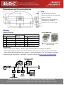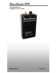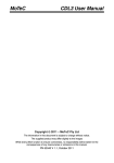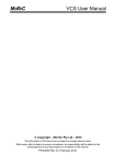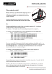
1
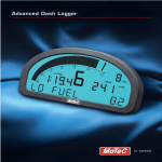
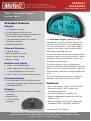
PRODUCT DATASHEET CDL3 #18022 rev 1.0 CDL3 - Club Dash Logger Part No. 18022 Standard features Display 70 segment bar graph 13 digit alphanumeric text bar 48 user-defined, scrollable message lines with programmable overrides 3 programmable 'pages' for Practice, Warm-Up and Race Adjustable backlight Internal Sensors 3-axis G sensor Dash temperature sensor The Club Dash Logger (CDL3) comes standard as a combined backlit display and powerful control device in one lightweight unit. With the addition of the Data Logging upgrade it becomes a fully programmable data logger with 8MB memory. It offers the same construction and advanced technology as the top of the line ADL3, with a package of features tailored to entry level motorsport requirements. Sensor supply voltage Battery voltage Buttons and Lights Alarm acknowledge button Mode, page and scroll line button 2 stage brightness control input SLM / SLM-C for shift and warning light The screen layout is fully configurable to display a multitude of data channels, warning alarms, lap times, fuel calculations, minimum corner speeds, maximum straight speeds and more. Communications The CDL3 performs calculations, acquiring data from other devices such as an ECU. 2 x configurable CAN or RS232 bus with individually programmable CAN bus speeds Features 1 dedicated RS232 All-in-one display, logger* and controller* Physical Suitable for bikes, cars, marine and industrial applications Dimensions 180 x 91 x 18 mm excluding connector Compact, durable and reliable unit Weight 385 g Supports Wideband Lambda from MoTeC PLMs or LTCs 1 x 34 pin AMP connector Easily integrates with MoTeC CAN-based expanders, GPS, shift lights and ECUs *Logging and I/O Optional (Continued on next page) MoTeC Pty. Ltd, 121 Merrindale Drive, Croydon South, Victoria 3136, Australia www.motec.com, Ph 61 3 9761 5050, Fax 61 3 9761 5051, [email protected] Product specifications are subject to change PRODUCT DATASHEET CDL3 #18022 rev 1.0 CDL3 - Club Dash Logger Optional Accessories Part No. 18022 CDL3 also available in Kits 18023—CDL3 Track Display Kit 18024 –CDL3 Track Logging Kit Optional features Inputs Or kit components separately 4 x Analogue voltage high resolution inputs 18122 SLM-C Club Shift Light Module 2 x Analogue temperature inputs 62203 Loom, CDL3 terminated 2 x Digital inputs 61221 Loom, two button 3 x Speed inputs with voltage measuring capability 41304 GPS L10, 10hz GPS Compatible with E888 expander (8 Thermocouples only) Additional options Outputs 4 x PWM, switched or digital outputs 61222 Terminated curly cord 61199 CDL3 to RS232 ECU 61198 CDL3 to MoTeC CAN ECU Logging 61197 CDL3 to OBD-II 8 MB logging memory 61196 CDL3 I-O Loom Logging rates up to 500 samples per second Fast Ethernet download Additional Information Compatibility MoTeC ECUs: M4, M48, M8, M84, M400, M600, M800 and M880 MoTeC Accessories: MDD, E888, SLM, PLM, LTC, BR2, PDM, GPS, VCS etc. Software Windows-based software designed for setup and management of the display and data logging system Generate a configuration file offline and then send this to the CDL3 Many non-MoTeC devices Calculations including lap times, lap gain/loss, speed and distance, fuel prediction PC Recommendations Monitor active channels Windows XP, Vista or Windows7 Sensor zeroing Screen size: 1024 x 768 Including details editor Processor speed: 1-2 GHz Pentium Extensive help screens 2 GB RAM User Manual and Software 256 MB graphics card 2 USB ports, 1 Ethernet port Latest versions available from www.motec.com/downloads. This will ensure it will run all MoTeC software. MoTeC Pty. Ltd, 121 Merrindale Drive, Croydon South, Victoria 3136, Australia www.motec.com, Ph 61 3 9761 5050, Fax 61 3 9761 5051, [email protected] Product specifications are subject to change PRODUCT DATASHEET CDL3 #18022 rev 1.0 Connector and Pinout Pin 1 2 3 Name E-TXE-TX+ AV1 Standard Function Ethernet Transmit Ethernet Transmit + Optional Function #29500 4 AV2 Analogue Voltage Input 2 5 AV3 Analogue Voltage Input 3 6 7 8 9 AV4 8V 5V 0V Sensor 8 V Sensor 5 V Sensor 0 V 10 E-RX- Ethernet Receive - 11 12 13 14 15 16 17 18 E-RX+ Ethernet Receive + DIG1 DIG2 AT1 AT2 CAN0L / RS232 0 RX Alarm Ack* Next Line* 19 20 21 22 23 24 25 26 27 28 29 30 31 32 33 34 CAN0H / RS232 0 TX TX SPD1 SPD2 SPD3 CAN0 Hi / RS232 0 TX RS232 Output CAN1L / RS232 1 RX CAN1H / RS232 1 TX RX AUX1 AUX2 AUX3 AUX4 BAT+ BAT- CAN1 Lo / RS232 1 RX CAN1 Hi / RS232 1 TX RS232 Input Analogue Voltage Input 1 Analogue Voltage Input 4 Digital Input 1 Digital Input 2 Analogue Temp Input 1 Analogue Temp Input 2 CAN0 Lo / RS232 0 RX Brightness Switch Speed Input 1 Speed Input 2 Speed Input 3 Auxiliary Auxiliary Auxiliary Auxiliary Output Output Output Output 1 2 3 4 Battery Positive Battery Negative *Press Alarm and Next together to change display mode. MoTeC Pty. Ltd, 121 Merrindale Drive, Croydon South, Victoria 3136, Australia www.motec.com, Ph 61 3 9761 5050, Fax 61 3 9761 5051, [email protected] PRODUCT DATASHEET CDL3 #18022 rev 1.0 Dimensions and Mounting Details Note: All dimensions in [mm] Ensure product is not stressed when mounted Dimensions indicate actual product size, allow for clearance when mounting Wiring Ethernet wiring CDL3 Pin numbering Function MoTeC loom Ethernet Connector colour Pin Function 11 Ethernet RX+ orange/white 1 Ethernet TX+ 10 Ethernet RX– orange 2 Ethernet TX– 2 Ethernet TX+ green/white 3 Ethernet RX+ 1 Ethernet TX– green 6 Ethernet RX– Pin Plug Socket Note: Cat 5 Ethernet cable must be used. ECU wiring When using an M4, M48 or M8 ECU, the CDL3 should be connected via RS232. The CDL3 should be connected via the CAN bus when using a ‘hundred series’ ECU M84/ M400/M600/M800/M880 and any number of other CAN devices. See the following example. Detailed wiring information is available in the user manual at www.motec.com/downloads. C MoTeC Pty. Ltd, 121 Merrindale Drive, Croydon South, Victoria 3136, Australia www.motec.com, Ph 61 3 9761 5050, Fax 61 3 9761 5051, [email protected]