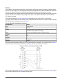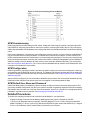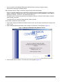
1
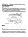
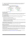
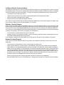
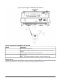
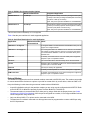
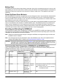
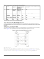
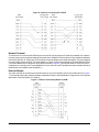
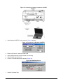
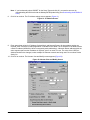
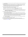
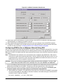
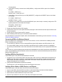
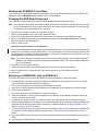
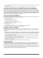
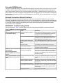
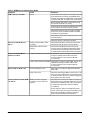
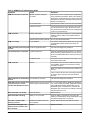
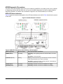
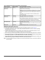
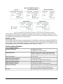
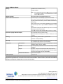
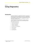
NCM45x0-2 Network Control Module Commissioning Guide
Code No. LIT-12011176
Software Release 6.0
Issued January 30, 2013
Supersedes October 4, 2010
Refer to the QuickLIT website for the most up-to-date version of this document.
Document Introduction.............................................................................................................3
Related Documentation.............................................................................................................3
NCM45x0-2 Commissioning Overview.....................................................................................3
About the NCM45x0-2 Network Control Module .............................................................................3
Metasys Network with the NCM45x0-2..............................................................................................4
Differences between NCM45x0-2 and NCM300 Series Controllers................................................4
Required Software..............................................................................................................................5
Supported NCM Types........................................................................................................................5
Supported Operator Devices.............................................................................................................6
Supported Communication Buses....................................................................................................6
Database Generation..........................................................................................................................6
Memory................................................................................................................................................6
Microprocessor...................................................................................................................................6
System Status LEDs...........................................................................................................................7
Communications.................................................................................................................................7
N1 Local Area Network.........................................................................................................................7
N2 Bus Communications......................................................................................................................7
LONWORKS Network Communications....................................................................................................8
Operator Terminal Support....................................................................................................................8
Network Terminal Support.....................................................................................................................8
RS232C Ports.......................................................................................................................................9
External Modem..................................................................................................................................10
Battery Pack......................................................................................................................................11
Power Up/Power Down Behavior....................................................................................................11
Resetting and Reloading the NCM45x0-2.......................................................................................11
Communication Port Comparison: NCM45x0-2 and NCM300 Series...........................................11
Cable Guidelines for RS232C Port Devices....................................................................................12
Configured or Unconfigured OWS......................................................................................................12
Operator Terminal...............................................................................................................................12
Network Terminal................................................................................................................................13
External Modem..................................................................................................................................13
Printers................................................................................................................................................14
NCM Commissioning........................................................................................................................15
NCM Configuration...........................................................................................................................15
NCM Default User Name and Password.........................................................................................15
Detailed Procedures................................................................................................................15
Setting the N2 Bus End-of-Line Switch..........................................................................................16
Downloading the NCM45x0-2 Code.................................................................................................16
Configuring the NCM with NCSETUP..............................................................................................21
Configuring NCM for Use on Metasys Network Using DDL..........................................................25
Connecting NCM to the Metasys Network..........................................................................................26
Verifying NCM Has Downloaded.........................................................................................................26
Verifying Online Status of NCM, Devices, and Objects......................................................................26
Verifying the NCM45x0-2 Code Base..............................................................................................27
NCM45x0-2 Network Control Module Commissioning Guide
1
Changing the NCM Default Password.............................................................................................27
Replacing an NCM350/361 with an NCM45x0-2..............................................................................27
Replacing an NCM That Uses the ARCNET Network with an NCM45x0-2...................................28
Replacing a Defective NCM45x0-2..................................................................................................28
Migrating an NCM to an NAE45.......................................................................................................28
Troubleshooting.......................................................................................................................28
Corrupted NCM Memory...................................................................................................................29
Network Connection Related Problems..........................................................................................29
NCM45x0-2 Troubleshooting Guide................................................................................................29
NCM Diagnostic Procedures............................................................................................................32
NCM LED Status Indicators................................................................................................................32
NCM Startup/Shutdown Sequence.....................................................................................................33
NCM Log Files...................................................................................................................................34
Technical Specifications..................................................................................................................34
NCM45x0-2 Network Control Module Commissioning Guide
2
Document Introduction
This document describes how to commission a Network Control Module (NCM) 45x0-2 in a Metasys® network. The
NCM45x0-2 emulates the NCM350/361 and operates with other Network Control Modules (NCMs), Network Control
Units (NCUs), Network Expansion Units (NEUs), Network Integration Engines (NIEs), and Operator Workstations
(OWSs) in the facility.
This document does not describe how to mount, wire, or turn on the NCM. Also, this document does not describe
how to build or download the NCM database, or how to configure an NCM to monitor and control a Building Automation
System (BAS).
Related Documentation
Table 1 lists documents related to the NCM45.
Table 1: Related Documentation
For Information On
Installing the NCM45x0-2
Installing the NCM45x0-2 as a
Replacement to Existing NCM350/361
Installing the NCM45x0-2 as a
Replacement to an NCM That Uses
ARCNET®
See Document
LIT or Part Number
NCM45x0-2 Series Network Control
Module Installation Instructions
Part No. 24-10249-18
N1 Ethernet/IP Network Technical Bulletin LIT-6360175
Using NCSETUP with the NCM45x0-2 NCSETUP for Windows® Operating
System Technical Bulletin
LIT-6360251d
Understanding How the N2 Bus Is
Integrated to the NCM
N2 Communications Bus Technical
Bulletin
LIT-636018
Understanding How the LONWORKS®
Network Is Integrated to the NCM
LONWORKS® Network Layout Technical
Bulletin
LIT-1162150
Overview of N2 Bus Controllers
Technical Bulletin for each N2 Bus field
controller
Various
Setting up NCM Database
DDL User’s Manual (offline method)
LIT-630010
Operator Workstation User’s Manual
(online method)
LIT-120165
GPL Programmer’s Manual
LIT-631010
JC-BASIC Programmer’s Manual
LIT-632010
Creating Processes for the NCM to
Execute
NCM45x0-2 Commissioning Overview
About the NCM45x0-2 Network Control Module
The Network Control Module 4500 Series (NCM45x0-2) is a fully user-programmable supervisory controller on the
Metasys network. The Network Control Module (NCM) coordinates and supervises the control activities for objects
and control loops connected to it from field controllers such as those that belong to the family of Application Specific
Controllers (ASCs).
The NCM integrates three streams of information:
•
•
system, database, and global information
application programs (Graphic Programming Language (GPL) and JC-BASIC processes)
•
data and Input/Output (I/O) information arriving from the communication ports
In addition, the NCM, via the N1 Local Area Network (LAN), can control activities for objects located in other NCMs.
An example of exchanged control would be objects shed or restored by the Demand Limiting/Load Rolling (DL/LR)
feature.
NCM45x0-2 Network Control Module Commissioning Guide
3
Note: Because the NCM45x0-2 emulates the operation of the NCM350/361, existing Metasys tools, such as
NCSETUP and the Metascan Data Collection Tool, can be used with the NCM45x0-2. However, the Metasys
software does not recognize the NCM45x0-2 as a new device type; rather, it identifies the NCM45x0-2 as
an NCM350.
Metasys Network with the NCM45x0-2
The NCM45x0-2 exists on the Ethernet portion of the N1 Network. Figure 1 shows an example of this type of
configuration with connections to some of the supported devices. As shown, a network that uses both ARCNET®
(Attached Resource Computer Network) and Ethernet nodes requires a Metasys Ethernet Router to handle
communication between the two segments of the network.
Figure 1: NCM45x0-2 with Other System Components
Differences between NCM45x0-2 and NCM300 Series Controllers
For those who are familiar with the NCM300 Series controllers, the following section outlines the most important
differences between the older models and the NCM45x0-2. If you are looking specifically for details on the
communication options, see Communication Port Comparison: NCM45x0-2 and NCM300 Series.
•
•
•
•
•
•
The NCM4510-2 model supports two NCM code download types: General with Operator Terminal (OT) and
General with Network Terminal (NT). The NCM4520-2 model supports one NCM code download type: General
with NT. No other NCM types are available on either model.
The NCM45x0-2 uses Ethernet exclusively. No model is available.
The NCM4510-2 model offers one N2 Bus, not two. The NCM4520-2 model offers one LONWORKS trunk.
The Ethernet, N2 Bus, and LONWORKS network components are built into the motherboard; separate network
cards are not required.
Memory is located on the motherboard and cannot be added to or removed.
The NCM45x0-2 offers two serial ports: RS232C A/Port 3 and RS232C B/Port 5. Port 3 on the older models is
equivalent to RS232C A/Port 3, and Port 5 is equivalent to RS232C B/Port 5. A device connected to Port 3 on
the NCM350/361 can be moved to RS232C A/Port 3 on the NCM45x0-2. A device connected to Port 5 on the
NCM45x0-2 Network Control Module Commissioning Guide
4
•
•
•
NCM350/361 can be moved to RS232C B/Port 5 on the NCM45x0-2. Serial Ports 2, 4, and 6 on the NCM350/361
models are not offered on the NCM45x0-2.
N1 communication at 10 or 100 Mbps is supported. Connection at 100 Mbps greatly increases the speed of
uploads and downloads.
The NCM45x0-2 is powered with a 24 VAC power transformer, ordered separately. The adapter requires a
standard power outlet near the NCM.
The code for the NCM45x0-2 is downloaded and updated with a tool called the Metasys NCM Update Utility,
available on the Branch Purchase Package (BPP). If you try to download both code and data from an Operator
Workstation (OWS), only the data is downloaded.
•
To return the NCM to factory condition, the device must be reflashed with the Metasys NCM Update Utility. There
is no switch or jumper on the NCM45x0-2 that can be used to return the unit to its default factory condition (Gate
1, Node 99). After the device is reflashed, it must be reconfigured with NCSETUP because the flash process
erases the Non-Volatile Random Access Memory (NOVRAM) settings.
•
The NCM45x0-2 is smaller than the NCM300 Series and in most situations can fit in the same location as the
NCM300 if it is replacing it.
The N2 Bus terminal connector on the NCM45x0-2 is called Field Controller (FC) Bus. Also, this connector has
four terminals, including a termination for an optional shield.
Two LEDs on the NCM45x0-2 indicate failure: Fault and Batt Fault. The LEDs do not indicate diagnostic error
codes, nor do they indicate the network address of the NCM while it is booting. For details, see NCM LED Status
Indicators.
•
•
•
•
•
•
Do not push the Reload switch (Figure 2) on the NCM45x0 to initiate a device reload. It does not have the same
function as the Reload button on the NCM300.
The NCM error log records the use of any invalid ports that may have been configured on the NCM45x0-2. To
determine if an invalid port is defined, open the NCM error log file from the OWS and look for the entry Error
Adding IO Device. Even though the controller functions normally with invalid ports defined, it is good practice
to correct invalid port definition.
If Serial Port 3 (RS232C A/Port 3 on the NCM45x0-2) is selected for OT use, a direct connection with NCSETUP
to that port is no longer available; in this case, use WNCSETUP from the OWS.
The NCM45x0-2 does not support remote NT connections. This capability is lost if an NCM45x0-2 replaces an
existing NCM300 that uses remote NT connections.
Required Software
The NCM45x0-2 requires Metasys Person-Machine Interface (PMI) Release 12.04 software. The M-Series Workstation
Software at Release 5.4 is also supported. With either system, be sure that the most recent Quick Patch has been
applied.
Supported NCM Types
The two NCM code download types that the NCM4510-2 (N2 Bus version) model supports are General with OT and
General with NT. For the NCM4520-2 (LONWORKS network) model, only the General with NT type is supported. No
other NCM download types are supported on either model.
Both NCM types support the following N2 Bus devices: Air Handling Units (AHUs), Variable Air Volume (VAV)
controllers, VAV Modular Assemblies (VMAs), Unitary (UNT) controllers, Lab and Central Plant Controllers (LCPs),
Phoenix Lab and Fume Hood (PHX) Interface Modules, DC-9100s, DR9100s, DX-9100s, TC9100s, Intelligent Fire
Controller (IFC-2020 or IFC-1010) panels, Extension Modules, Generic Vendor Devices, and Metasys Integrator®
units.
For the NCM with the LONWORKS network, these devices are supported: DX9200, TCU1200, VMA1200 and other
non Johnson Controls® LONWORKS compatible devices.
Unsupported devices include: Intelligent Lighting Controller (ILC), Intelligent Access Controller (IAC-600), N2 Dialer
Module (NDM), and DX9120/DX9121. The various migration NCM types, such as Network Port, S2 Migration, and
JC/85 Gateway, also are not supported.
NCM45x0-2 Network Control Module Commissioning Guide
5
Supported Operator Devices
The three user devices that can communicate with the NCM are the OWS, OT, and NT. When connected, these
devices can display, schedule, and control applications connected to this and any other NCMs on the network.
Supported Communication Buses
The NCM supports the N2 Bus or LONWORKS network. It does not support N2E (N2 communication on Echelon®
network), L2, or a second N2 Bus.
Database Generation
Data Definition Language (DDL) is used to generate the NCM database offline. If the online method is preferred,
the OWS can be used. Once the NCM is configured with NCSETUP, its database can be downloaded from the
workstation. Unlike older NCM models, the code for the NCM45x0-2 is not downloaded from the OWS. This function
is accomplished with the Metasys NCM Update Utility. (For details, see Downloading the NCM45x0-2 Code.) If you
try to download code and data from the workstation, only the data portion is downloaded.
Figure 2 illustrates the basic components of the NCM. These components are referred to throughout this document.
Figure 2: NCM45x0-2 Components
Memory
The NCM45x0-2 contains 128 MB Synchronous Dynamic Random Access Memory (SDRAM) and 128 MB of Flash
memory on the motherboard, which cannot be added to or removed. The NCM45x0-2 is designed to emulate the
capacity of the NCM350/361 with 10 MB installed. Also, like the NCM350/361, the NCM45x0-2 allocates 8 MB of
available memory for use by the application database.
Microprocessor
The microprocessor applies the various supervisory programs to the combined data, and exercises control over the
modules and devices that connect to the NCM via a local bus. This supervision and control operate in the same
manner when either of the NCM code types is selected.
The NCM45x0-2 Central Processing Unit (CPU) has more processing bandwidth than the older NCM300 Series
controllers. This is evident when viewing the idle time reported by NCSETUP. The %idle time for the NCM45x0-2
may be higher than that reported by an NCM350 when running the same database; however, the idle time as reported
by each device is accurate.
NCM45x0-2 Network Control Module Commissioning Guide
6
Note: A high %idle for a NCM4500 does not indicate that the NCM45x0 can support more field devices than a
NCM350, and does not ensure reasonable service time with an Network Integration Engine (NIE).
System Status LEDs
The NCM has nine LEDs that indicate power and status information (Figure 3).
Figure 3: NCM45x0-2 Status Indicators
For the purpose of each LED, see Table 8.
Communications
The I/O subsystem supports a multi-user environment consisting of network connections (N1 network and integrated
N2 Bus or LONWORKS network) and direct I/O communication (OT, NT, and printer using the RS232C ports).
N1 Local Area Network
The N1 LAN allows communication with both OWSs and other NCMs on the network. The Ethernet circuitry is built
into the NCM45x0-2 motherboard.
Each NCM and OWS on the system contains a Node Manager task, whose responsibilities include:
•
•
•
•
•
broadcasting once per minute that it is still online
listening to other node managers to track on and offline devices
issuing a time stamp for every global database in its memory
comparing the time stamps of its own databases to the received time stamps of other node managers’ databases,
and updating the current database if necessary
monitoring the printer for online or offline status
The device with the lowest address number on the network issues time and date information every 4 hours to ensure
system synchronization. A clock/calendar chip backs up time and date information. This Node Manager also monitors
broadcasts and issues online/offline advisories.
In the event of a severed N1 network, each separated LAN forms an independent network.
N2 Bus Communications
The NCM4510-2 has a built-in FC bus called the N2 Bus (RS-485) that allows it to communicate with a variety of
field controllers. Devices on the N2 Bus constitute a local network, controlled by the NCM. The NCM polls the devices
according to a user-set priority level, which is set at the Definition window at each device. In most cases, the default
priority level is sufficient.
The N2 Bus connects in a daisy-chain fashion and provides the transmission medium for external devices (field
controllers such as the Air Handling Unit (AHU), UNT, Lab and Central Plant Controller (LCP), DX-9100, Digital
Control Module (DCM), and IFC-1010/IFC-2020 Indoor Fan Contractor (IFC).
Each end of the N2 Bus is terminated with an EOL termination resistor provided by a switch. For information on
setting the N2 Bus EOL switch, see Setting the N2 Bus End-of-Line Switch in this document.
NCM45x0-2 Network Control Module Commissioning Guide
7
LONWORKS Network Communications
The NCM4520-2 has a built-in LONWORKS network interface that allows it to communicate with a LONWORKS network
of compatible devices. The LONWORKS network carries all communication between the NCM and LONWORKS compatible
devices and between the devices themselves. The types of data that are transferred across the network include:
•
•
•
•
commands from the NCM to the devices
responses from the devices to the NCM, including identification and requested data values
time synchronization messages from the NCM
analog and binary point data shared between devices
The LONWORKS network uses End-of-Line (EOL) terminators to balance the communication signals. For details, refer
to the LONWORKS Network Layout Technical Bulletin (LIT-1162150).
Operator Terminal Support
An OT can be connected to either of the RS232C ports, but if you select RS232C B/Port 5, direct connection to the
RS232C A/Port 3 is still available with NCSETUP. Both the direct-connect and dial-up connect options are supported.
To use the OT function, select General with OT and its serial port while commissioning the NCM with NCSETUP.
All OT functions, such as displaying summary and trend information, commanding objects, and performing schedule
operations, are available. The choices for running the OT software are:
•
•
VT100 terminal or VT220 terminal running in VT100 mode
computer running VT100 emulation software, such as provided by HyperTerminal®, an application that comes
with all Microsoft® Windows® operating systems
For full details on using the OT with the NCM, refer to the Operator Terminal Technical Bulletin (LIT-636015).
Network Terminal Support
An NT can be connected to RS232C B/Port 5 to provide for all available NT functions; however, there are a few
restrictions:
•
•
•
•
•
Connect the NT to RS232C B/Port 5 only; communication is at 9600 baud.
Use the special cable kit to connect the NT to the NCM45x0-2 serial port (refer to Table 8 in the NCM45x0-2
Series Network Control Module Installation Instructions [Part No. 24-10249-18]). The kit contains a serial port
adapter and a power adapter. The serial adapter is connected to the RS232C B/Port 5 port on the NCM (Figure
4), and the standard NT cable connects between one of the NT jacks and the back of the serial adapter. This
cable provides the data connection. The power adapter connects between AC power and the other NT jack, to
provide the power connection. The NT jacks are identical, which means either jack can accept data or power.
Provide AC power for the NCM4500 NT Cable Kit within 6 feet of the NCM.
Connect to the NT locally only; remote connection to the NT via modems is not supported.
Keep the RS232C B/Port 5 as an unconfigured port. If configured for a purpose, NT operations are not available.
NCM45x0-2 Network Control Module Commissioning Guide
8
Figure 4: Connecting NT to NCM45x0-2 with Cable Kit
Table 2: Connecting NT to NCM45x0-2 with Cable Kit
Callout
Description
1
RS-232C B/Port 5 Serial Port
2
Insert serial port adapter into RS232C B/Port 5. Connect NT cable into back of serial
adapter.
3
Connect Adapter to Back of NT and to 120 VAC power.
4
NT (back view)
Note:
The NT jacks are identical, so either can be used for power or data.
RS232C Ports
Two RS232C serial ports on the NCM45x0-2 provide input/output at standard RS232C levels using the Data Terminal
Equipment (DTE) protocol. They provide for several communication options. See Table 3.
NCM45x0-2 Network Control Module Commissioning Guide
9
Table 3: RS232C Port Communication Options
Port
Maximum Baud Rate
RS232C A/Port 3
Supported Application
19,200 bps
Printer (direct or dial-up connection) Configured OWS (direct
or dial-up connection) Unconfigured OWS (direct connection)
OT (direct or dial-up connection)
Note: This port is equivalent to Port 3 on an NCM350/361.
RS232C B/Port 5
Printer (direct or dial-up connection) Configured OWS (direct
or dial-up connection) Operator Terminal (direct or dial-up
connection) NT (direct connection only)
1
56,700 bps
Note: This port is equivalent to Port 5 on an NCM350/361.
1 Do not select a baud of 28,800 bps. It is not supported.
Table 4 lists the port restrictions for each supported application.
Table 4: Serial Port Restrictions for each Application
Application
Maximum Number Notes
of Connections
OWS Direct - Configured
2
A configured OWS is an OWS defined in the database. Each port can
support one configured OWS.
OWS Direct - Unconfigured
1
An unconfigured OWS is an OWS that is not defined in the database
(for example, a laptop computer). Use it to run logs and summaries,
or to download the database. It cannot be connected directly to the
Ethernet LAN.
OWS Dial
1
A remotely connected OWS on one of the serial ports is supported.
Requires a pair of compatible modems.
OT Direct
1
You cannot have both a direct and dial-up OT on the same NCM.
OT Dial
1
Requires a pair of compatible modems. You cannot have both a direct
and dial-up OT on the same NCM.
NT Direct
1
Can only be used by NT application.
NCM Printer Direct
1
A directly connected printer on one of the serial ports is supported.
NCM Printer Dial
1
A remotely connected printer on one of the serial ports is supported.
Requires a pair of compatible modems.
External Modem
The NCM45x0-2 supports the use of two external modems connected to its RS232C ports. The modems can provide
for remote annunciation of alarms to a printer or provide for remote dial-in by a user device, either an OWS or OT.
Keep the following in mind when using an external modem with an NCM45x0-2:
•
A specific initialization string for the particular modem you are using must be configured with NCSETUP. Refer
to the NCSETUP for Windows Operating System Technical Bulletin (LIT-6360251d).
•
The external modem is connected directly to either port by using a cable with the proper pinouts (see Cable
Guidelines for RS232C Port Devices). Once the port is configured for a modem, it is no longer available for direct
connect diagnostics using NCSETUP.
Only one dial-up OWS, OT, or printer can be connected to the NCM.
•
•
The baud rate for a modem connected to a dial-up printer must be programmed to connect at 9600 bps using
the S37=9 parameter.
NCM45x0-2 Network Control Module Commissioning Guide
10
Battery Pack
The NCM comes from the factory with its battery connected. As part of the commissioning process, be sure to verify
that the battery is connected. It provides a method of saving the database from Dynamic Random Access Memory
(DRAM) into Flash memory when the unit is turned off or a power outage occurs. The database is then saved
indefinitely.
Power Up/Power Down Behavior
When the NCM45x0-2 is turned on, it runs through a series of diagnostic checks. If an internal fault is detected after
the unit is fully operational, the FAULT LED turns on red momentarily, then turns off. If a fault with the battery is
detected, the BATT FAULT LED stays on red. The LEDs do not indicate any particular error condition code, nor do
they indicate the current node number of the device.
When the NCM45x0-2 is turned off, either manually or by a power failure, the operational database is stored to Flash
memory. The database is then stored for an indefinite period of time. This database protection is provided by the
battery, which is charged by the 24 VAC supply power to the NCM. At initial startup, the battery may require a
charging period of at least 4 hours before it supports data protection if power fails. Maximum protection (up to three
consecutive power failures without recharging time) requires a 15-hour charging period.
Resetting and Reloading the NCM45x0-2
The NCM can be manually reset or reloaded from the OWS or from NCSETUP. An NCM reset initiates an orderly
reset that saves recent changes to the NCM database. An NCM reload restarts the operating system, then forces
a database-only download from the archive workstation.
Note: Whenever the NCM download code type is changed in NOVRAM, the change does not go into effect until
the NCM is reset or reloaded.
Note: The reload process does not download the code to the NCM45x0-2 also. This is accomplished with the
Metasys NCM Update Utility. For details, see Downloading the NCM45x0-2 Code.
Important: Pressing the Reload switch on the NCM (Figure 2) may cause flash corruption, rendering the device
inoperable until it is reflashed with the Metasys NCM Update Utility; therefore, we highly recommend
that if you need to reload or reset the NCM, do so from an OWS or with NCSETUP.
Communication Port Comparison: NCM45x0-2 and NCM300 Series
Here is a comparison chart that shows the choices for each Network Communication Module (NCM) port for the
NCM300and NCM45x0-2 Series. Select only one option per port.
Table 5: Communications Port Comparisons between Models
Port
No.
Port Type
NCM300 Series
NCM45x0-2
Label/Location Use
Label
NCM4510-2 Use
NCM4520-2 Use
1
RS-485
I
N2 Bus 1
FC Bus
N2 Bus 1
N/A
2
RS-232C
II
N2 Bus 2
N/A
external CVT or
Printer (direct
or dial-up) or
OWS (direct or
dial-up) or OT
N/A
3
RS-232C
III
Printer (direct RS232C
or dial-up) or
A/Port 3
OWS (direct or
dial-up) or
Unconfigured
OWS or OT
Printer (direct or dial-up) or OWS (direct or dial-up)
or Unconfigured OWS or OT
NT (RJ11) or
OT (RS232C)
N/A
4
RS-232C or RJ11
IV
NCM45x0-2 Network Control Module Commissioning Guide
N/A
Note:
Operator Terminal cannot be used with
the NCM4520-2 Model
11
Table 5: Communications Port Comparisons between Models
5
RS-232C
ISA Slot A
(optional)
Printer (direct RS232C
or dial-up) or
B/Port 5
OWS (direct or
dial-up) or OT
Printer (direct or dial-up) or OWS (direct or dial-up)
1
or NT or OT
6
RS-232C
ISA Slot B
(optional)
Printer (direct N/A
or dial-up) or
OWS (direct or
dial-up) or OT
N/A
-
Ethernet
ISA Slot A
(optional)
Ethernet(10
Mbps)
Ethernet
Ethernet(10/100 Mbps)
-
ARCNET®
ISA Slot A
(optional)
ARCNET
Network
N/A
N/A
-
LONWORKS Network ISA Slot B
(optional)
LON
LON
N/A
-
USB
N/A
USB
N/A
N/A
LON
1 Operator Terminal cannot be used with the NCM4520-2 Model.
Cable Guidelines for RS232C Port Devices
A variety of devices can be connected to the RS232C ports on the NCM. The cable required for each device is
described and illustrated in this section. As a general rule, use shielded cable for all RS232C connections to third-party
equipment.
Configured or Unconfigured OWS
The cable required for connecting a configured or unconfigured OWS to one of the RS232C ports on the NCM is
shown in Figure 5. This is a null modem serial cable with a 9-pin female connector on both ends.
Figure 5: Cable for Connecting OWS Serial Port to NCM
Operator Terminal
To connect the OT to either RS232C port on the NCM, a 9-pin connection from the NCM serial port to either the
25-pin serial port or 9-pin serial port of the VT100 or computer is required. See Figure 5 or Figure 6. A null modem
serial cable such as the one shown in Figure 6 can also work if using a computer running HyperTerminal.
NCM45x0-2 Network Control Module Commissioning Guide
12
Figure 6: Cable for Connecting OT to NCM
Network Terminal
To connect the NT to the second RS232C port on the NCM, use the special NT cable kit purchased from Johnson
Controls (refer to the Accessories Ordering Information in the NCM45x0-2 Series Network Control Module Installation
Instructions [Part No. 24-10249-18]). The kit consists of a power adapter and a serial port adapter. The power adapter
is used to supply power to the NT. The serial adapter is a 9-pin connector that attaches to the NCM RS232C B/Port
5 to provide data to the NT. Make the connections as shown in Figure 4. (This special cable kit is the only kit that
we support for connecting an NT to the NCM45x0-2. Once connected, all NT operations that are available with other
NCM models are available at the NCM45x0-2.)
External Modem
The cable required for connecting an external modem to one of the RS232C ports on the NCM is shown in Figure
7. The external modem also requires software configuration. Refer to General Modem Configurations in the Operator
Workstation Technical Bulletin (LIT-636013).
Figure 7: Cable for Connecting Modem to NCM
NCM45x0-2 Network Control Module Commissioning Guide
13
Printers
The NCM45x0-2 only supports printers with a serial interface; USB printers are not permitted. Acceptable printers
are those you can configure to a Lexmark® Proprinter® emulation mode and have either an available serial connection
option or the ability to connect to the NCM through a bidirectional RS232C serial-to-parallel converter.
If you are using the Color Printing feature for printing alarms, do not connect the color printer to the NCM. The printer
must be connected to the OWS for color printing to work. Refer to the Operator Workstation Technical Bulletin
(LIT-636013) for details.
The printer cable diagrams in Figure 8 and Figure 9 are typical but may not be exact for your interface.
To properly configure the printer for the NCM, use the individual printer instructions as a guide to set the mode and
DIP switches to the configurations shown in Table 6.
Table 6: DIP Switch Configuration for Printer
Configuration
Value
Card
Serial interface
Mode
RS232C
Polarity
No reverse polarity (Typically this setting could change, depending on the
individual computer system and cabling.)
Baud
Set to the rate established in DDL. The default is 9600.
Data Bits
8
Parity
No
Stop Bits
1
Protocol
XON/XOFF
Operation
Normal
The printer connects to either RS232C A/Port 3 or RS232C B/Port 5 of the NCM, or to a remote modem. Figure 8
shows the printer connections to the RS232C port; Figure 9 shows connections to the modem.
Figure 8: Cable for Connecting Printer to NCM
In printer dial-up applications, see Figure 7 for the pin connections from the NCM to the local modem. Figure 9 shows
the connections between the remote modem and the printer.
NCM45x0-2 Network Control Module Commissioning Guide
14
Figure 9: Cable for Connecting Printer to Modem
NCM Commissioning
NCM commissioning includes setting the EOL switch, loading the Flash image (if required), configuring the NCM
with NCSETUP, configuring the NCM as a node on the network, connecting the NCM to the N1 LAN, verifying the
OWS has downloaded the NCM database, and verifying that all devices and objects defined in the NCM are reporting
online.
Each network installation, commissioning, and configuration scenario is unique. In some scenarios, the NCM45x0-2
may be commissioned and configured before it is installed and connected to the network. In other scenarios, the
NCM is mounted and wired to the network before it is commissioned and configured. The unit can be commissioned
away from the job site because, unlike the older versions of the NCM, a sufficiently charged battery on the NCM45x0-2
allows the storage of the full database to Flash memory, which saves the database indefinitely. (For more details,
see Power Up/Power Down Behavior.) The 72 hour maximum database backup limitation of the NCM350/361 does
not apply to the NCM45x0-2 Series model.
NCM Configuration
NCM configuration is preparing the NCM to operate on a specific network site, and communicating with, monitoring,
and controlling specific BAS field devices on that site. The Metasys PMI Software provides the tools for adding the
NCM45x0-2 and the field controllers and objects it supervises and controls. See Configuring NCM for Use on Metasys
Network Using DDL.
After an NCM is configured, you can download its database using the OWS. After a successful download, the new
NCM and its field controllers and objects come online and appear on the Metasys Network Map.
NCM Default User Name and Password
Unlike older NCM models, the NCM45x0-2 Series controller includes an internal user name and password. They
are used by the NAE Configuration Tool (NCT) to access the controller for gathering diagnostic information. Metasys
PMI software does not make use of this user name and password, but there is a procedure for changing the default
password if required for security reasons. See Changing the NCM Default Password.
Detailed Procedures
To perform the following procedures and commission the NCM45x0-2, you should have:
•
a laptop or desktop computer with the Metasys NCM Update Utility, which is available on the BPP
•
1 FS10x 10/100 Netgear® switch (for example, FS105NA Netgear 5 Port or 10/100 is CompuCom #464163,
Model FS105NA) or 1 W-Linx 5-port 10/100 Mini Hub (USB) E63746 (part number SW-005CM-X) or 1 Netgear
5 Port or 10/100 Desktop switch (model FS605) connected to your computer
NCM45x0-2 Network Control Module Commissioning Guide
15
Note: Do not use any other hub or dual-speed hub.
•
•
•
•
the Media Access Control (MAC) address of each NCM you want to update (MAC address sticker located on
the unit)
null-modem serial cable (9-pin female)
2 RJ45 Ethernet patch cables (equivalent to CompuCom #131740, Model A3L791-07)
a new, unique IP address for each NCM you want to commission
Setting the N2 Bus End-of-Line Switch
Network and field devices at either end of the N2 Bus must be set as network terminated devices. The NCM4510-2
model has an EOL switch that is located to the left of the N2 Bus (FC Bus) termination block (Figure 2). The NCM
is shipped with the EOL switch in the factory default, ON (up) position (Figure 10). Set the EOL switch to the
appropriate position for each NCM in your network. For more details, refer to the Setting Terminations section of
the N2 Communications Bus Technical Bulletin (LIT-636018).
Figure 10: End-of-Line Switch on NCM45x0-2
Downloading the NCM45x0-2 Code
This step is only required if the NCM has lost its code (flash image) that was originally installed in the factory, or a
code update is required. If you cannot communicate with the NCM using NCSETUP, then another download may
be required to return the unit to its factory state. A tool called the Metasys NCM Update Utility is used. If an update
to the flash image is not required, go to the next section, Configuring the NCM with NCSETUP.
Important: This process clears out the NOVRAM settings in the NCM, so before you update a commissioned NCM
with the Metasys NCM Update Utility, be sure to record the NCM NOVRAM settings so that you can
reenter them after the code download is complete.
No other devices besides the computer and NCM should be connected to the Ethernet switch or hub during the
update process.
The Metasys NCM Update Utility will normally be run on the following computers:
•
a computer used for normal NCM configuration, such as a computer with Microsoft Windows 2000 Professional,
or Microsoft Windows XP® Operating System (OS) with SP1, and with Microsoft .NET Framework 1.1 installed.
•
a computer that has the Microsoft Windows 7 32-bit OS Professional, Enterprise, or Ultimate Edition installed,
provided this computer and the NCM45x0 are the only devices on the network. You cannot use this computer
for other NCM configuration tools.
The Metasys NCM Update Utility has the following characteristics:
•
can change an NAE45 back to an NCM45x0-2 if it was originally a factory NCM45x0-2 (the update is reversible)
Note: The Microsoft Windows 7 OS requires Java® Runtime Environment (JRE) 1.6.0.16. If you are using the
Microsoft Windows 7 OS and browsing to an Network Automation Engine (NAE) at Release 4.1 or earlier,
an attempt is made to download an earlier version of the JRE which may not run properly. with the Microsoft
Windows 7 OS.
•
•
•
•
•
should not be used to convert a factory NAE45 into an NCM45x0-2; if this occurs, the Metasys NAE/NIE Update
Tool must be used to update the NAE45 with the NAE code.
updates only one NCM45x0-2 at a time
updates either an NCM4510-2 or NCM4520-2 controller
should not be used at the same time as the NAE/NIE Update Tool is being used
clears out the NOVRAM settings of a commissioned NCM
NCM45x0-2 Network Control Module Commissioning Guide
16
•
•
only one instance of the Metasys NCM Update Utility should be running in computer memory
should not be used across a building network
Other important factors to keep in mind when using this utility include the following:
•
•
•
Before you start the update process, make sure the computer has an IP address assigned. If no address is
present, configure the Transmission Control Protocol/Internet Protocol (TCP/IP) properties to use a static IP
address (for example, 169.254.10.1 with submask 255.255.0.0).
The cables used to connect to the switch or hub should be Category 5 computer network cables; crossover
cables should not be used.
The FAULT LED is On during the update process, which is normal.
To download or update the code for the NCM:
1. Connect the computer and NCM to the Ethernet switch or hub. Turn on power to the NCM, the computer, and
switch or hub.
2. Start the Metasys NCM Update Utility on the computer. The Welcome screen appears (Figure 11).
Figure 11: Metasys NCM Update Utility Welcome Screen
3. Click the Next button to continue. The Connection screen appears (Figure 12).
NCM45x0-2 Network Control Module Commissioning Guide
17
Figure 12: Connection Screen
4. Click the Next button to continue. The MAC Address Entry screen appears (Figure 13).
Figure 13: MAC Address Entry Screen
Note: A selection for Update type is given, with Quick as the default. The Extended update takes much longer
to complete. Do not use unless Technical Support requests that you do so.
NCM45x0-2 Network Control Module Commissioning Guide
18
5. Select Quick and enter the MAC address of the NCM you want to flash. Refer to the MAC address sticker on
the unit.
6. Press the Next button. The Update Device screen appears (Figure 14).
Figure 14: Update Device Screen
7. Click the View Log button if you want to display the log window that shows progress messages. Click Update
Device. The Waiting for Response Screen appears (Figure 15).
8. Cycle power to the NCM or issue an NCM Reload command from the OWS. Within a minute or so, the update
process starts.
NCM45x0-2 Network Control Module Commissioning Guide
19
Figure 15: Waiting for Response Screen
During the update, a Progress screen indicates the approximate time left in the process (Figure 16).
Figure 16: Download Progress Screen
If the update was successful, the Completion screen appears (Figure 17). If the update was unsuccessful,
this screen indicates that the NCM update failed. Recheck the cable connections and try again.
NCM45x0-2 Network Control Module Commissioning Guide
20
Figure 17: Completion Screen
9. If you need to update another NCM, click Continue, which returns you to the Welcome screen (Figure 11). If you
have no other devices to update, click Exit.
Note: When you have updated all devices, we recommend that (for future use) you copy the Metasys NCM
Update Utility to the archive OWS computer under the C:\FMS folder.
The RUN LED on the NCM should be flashing, indicating its database has not yet been downloaded. Go to
Configuring the NCM with NCSETUP.
Configuring the NCM with NCSETUP
The stand-alone version of Windows NCSETUP is used to initially communicate and configure a new or updated
NCM45x0-2. NCSETUP establishes the NCM configuration and parameters in flash memory. This information sets
the archive data path, the port designations and values, the NCM code type, the dial-up phone numbers when
applicable, and other parameters. Follow these steps to configure the unit:
1.
Connect a null-modem cable between the serial port on the laptop computer (COM1 or COM2) and RS232C
A/Port 3 on the NCM (Figure 18). Do not use RS232C B/Port 5.
NCM45x0-2 Network Control Module Commissioning Guide
21
Figure 18: Connecting a Laptop Computer to the NCM
2.
Start Windows NCSETUP on the computer. Figure 19 appears.
Figure 19: First Screen of Windows NCSETUP
3.
4.
5.
Enter an NC Gate of 1 and an NC node of 99.
Specify which serial port on the computer you are using.
Specify 19200 as the baud rate.
6.
Click OK. The NCM Setup screen appears (Figure 20).
Figure 20: NCM Setup Screen
7.
Select IP for Setup Type.
NCM45x0-2 Network Control Module Commissioning Guide
22
Note: If you inadvertently select ARCNET for the Setup Type and click OK, you need to start over by
re-downloading the NCM code with the Metasys NCM Update Utility (see Downloading the NCM45x0-2
Code).
8.
Click OK to continue. The IP Address settings screen appears (Figure 21).
Figure 21: IP Address Screen
9.
Enter appropriate values for IP Address, Subnet Mask, and Network Router. All three address entries are
required, even if the direct or dialup application is intended for this NCM. The IP address for the NCM must be
a static IP address (NCM45x0-2 does not support dynamic addressing). A Network Router address within the
same segment space as the IP address is required, even if no router is in use. The value of the UDP Port
Address should not be changed, unless multiple N1 Ethernet networks are being used. Do not select Packet
Sanity On.
10. Click OK to continue. The Novram View and Modify screen appears (Figure 22).
Figure 22: Novram View and Modify Screen
NCM45x0-2 Network Control Module Commissioning Guide
23
11. For the NCM Address, enter a gate and node for the NCM. These settings are required even though the NCM
is an Ethernet device.
12. Specify the Network Name and the Code Download Type. If this is an NCM4510-2 (N2 Bus), the only valid
download types are General with NT and General with OT. If this is an NCM4520-2 (LONWORKS network), the
only valid download type is General with NT. No other types are supported for either model.
13. Under the Archive Device Address section, select the Port option as follows:
IP: the archive OWS and NCM are connected on N1 Ethernet.
Port 3: NCM is connected to the archive workstation via RS232C A/Port 3 (direct or dial-up).
Port 5: NCM is connected to the archive workstation via RS232C B/Port 5 (direct or dial-up).
Note: The only valid selections for Port are IP, Port 3 (RS232C A/Port 3), and Port 5 (RS232C B/Port 5). The
other ports are not available, and if you make an incorrect selection, the NCM is not able to obtain its
database from the archive workstation.
14. Under the Archive Device Address section, follow these steps:
a. If the archive OWS is connected to the NCM over the N1, specify the gate and node for that workstation.
Also enter the workstation IP address.
b. If the archive OWS is connected directly or remotely to an NCM serial port, select which port is being used
for the connection. Specify the gate and node of the NCM itself. If this is a remote connection, select Check
if Dial. Then, select the port a second time to enable the Port Baud Rate and dial settings. Enter the Port
Baud Rate and dial settings that are to be used to contact the remote workstation.
Note: If the archive OWS is communicating with the NCM on Port 5, do not select 28800 for the Port Baud
Rate. It is not supported.
15. Keep the Port 3 Baud Rate (RS232C A/Port 3) at 19200.
16. Do not change the Reboot on DownLoad Error setting. The NCM45x0-2 ignores this setting.
17. If this is a LONWORKS network model (NCM4520-2 only), select the LONWORKS Parameters option from the
Command menu. Figure 23 appears.
NCM45x0-2 Network Control Module Commissioning Guide
24
Figure 23: LonWorks Parameters Setup Screen
18. Specify the LONWORKS parameters as required, referring to the NCSETUP for Windows Operating System
Technical Bulletin (LIT-6360251d) for details. Click OK.
19. When satisfied with the NOVRAM settings, click OK to save your changes. Close all NCSETUP windows.
20. Configuration of the NCM is now complete. Disconnect the cable between the computer and the NCM serial
port. Go on to the next section, Configuring NCM for Use on Metasys Network Using DDL.
Configuring NCM for Use on Metasys Network Using DDL
After you have configured the NCM using NCSETUP, you need to configure its database using the DDL. If you wish
to perform these steps online at the OWS, refer to the Defining Devices section of the Operator Workstation User’s
Manual (LIT-120165). For details on the DDL steps mentioned in this section, refer to the DDL Programmer’s Manual
(LIT-630010).
Note: The NCM45x0-2 has a different set of communication ports compared to the NCM350/361. DDL restricts
some ports to certain device types and baud rates. If a port is specified in DDL that does not exist, no error
is generated at DDL compile time or after download of the database to the NCM. If this were to occur, the
NCM ignores the port, since no physical connection exists.
Important: Do not use the following unsupported DDL/UNDDL keywords with the NCM45x0-2: C210A, C260A,
CARD, D600, DELCARD, DELTZ, DSC, DSC8500, FPU, LCD, LCG, READER, and TIMEZONE.
1. Log on to the Metasys OWS and perform a global upload. Shutdown the OWS and de-compile the Workstation
Network/Port and Global files with UNDDL. Rename the .UND (de-compiled) files to .DDL source files.
2. Edit the Global source file as necessary to add the NCM as a new device on the network. All address, port,
and phone number entries must match what you specified earlier with NCSETUP.
a. Add the NCM to the Global file. If this NCM will be connected on the N1 Ethernet (N1DIRECT), also specify
the correct subnet address, node address, and static IP address. If the NCM code type is General with NT,
use 9600 for the NT baud rate. Example:
NC "NC45", "NCM4500",,, 1, 45, "N2",, "ENG", 9600
NCM45x0-2 Network Control Module Commissioning Guide
25
IP 192,9,205,40
b. If this NCM is remotely connected to an OWS (NCDIAL), configure the NCDIAL option in the Global file.
Example:
PC "OWS1", "OWS Floor 1"
NCDIAL "NC2", 3, 9600,"555-1111"
c. If this NCM is connected directly to an OWS (NCDIRECT), configure the NCDIRECT option in the Global
file. Example:
PC "OWS2", "OWS Floor 2"
NCDIRECT "NC45", 3, 9600
d. If a printer is to be attached to one of the NCM RS232C ports, either locally or remotely, configure the PTR
keyword parameters in the Global file. Example:
PTR "PTR1", "Printer Floor 1"
3.
4.
5.
6.
NCDIRECT "NC1", 3, 9600
Compile the Global file with the DDL Compiler.
Create the NC source file for this particular NCM, specifying the field controllers and the objects defined under
the field controllers.
Compile the NC source file with the DDL Compiler.
Start the Metasys OWS and log on. Download the Global database.
Once the database is created and compiled, and the Global database is downloaded, go to the next section Connecting
NCM to the Metasys Network.
Connecting NCM to the Metasys Network
After the NCM has been configured as a new node on the network, it can be connected to the Metasys network.
Before connecting, log on to the OWS.
•
•
•
For an NCM on N1 Ethernet, connect a standard Ethernet patch cable between the NCM and the N1 LAN.
For a remote NCM, initiate a call from the OWS to the NCM and verify a reliable connection is established.
For a directly connected NCM, connect the serial cable from the OWS serial port to the appropriate NCM serial
port.
The next step is to verify the NCM requests a download of its database from the OWS. Note that for the NCM45x0-2
model, only the database needs a download, not the code, because the code was downloaded previously with the
Metasys NCM Update Utility.
Verifying NCM Has Downloaded
Follow these steps to verify that the NCM initiates the download:
1. If logged off, log on to the archive OWS. Verify that within a few moments, the NCM initiates a download of its
database from the archive workstation. If the download does not start, perhaps it already occurred. To verify,
check whether the NCM is reporting an online status. If the NCM is offline, cycle power on the NCM, which
initiates the download if one is required.
2. Verify that the NCM download completes successfully.
The last step is to verify the NCM and its devices and objects come online.
Verifying Online Status of NCM, Devices, and Objects
Follow these steps to verify the status of the NCM, its devices and objects:
1. Log on to any OWS. If the new NCM is not shown on the Network Map, download the Global database.
2. Double-click on the NCM in the Network Map to verify its status is Online.
3. Open all devices under the NCM and verify each is online.
4. Open the object window for each device and verify that all objects come online.
NCM45x0-2 Network Control Module Commissioning Guide
26
Verifying the NCM45x0-2 Code Base
If you need to verify that an NCM contains the NCM45x0-2 code, open the Information screen in NCSETUP. The
NCM type is listed as NCM350 and the firmware version is listed as 000.
Changing the NCM Default Password
If this installation requires a change to the NCM default internal password, follow these steps.
Note: As a prerequisite, a computer with the NAE Configuration Tool (NCT) software is required. Also, this computer
must be connected on the same network as the NCM. For details on how to use the NCT, refer to the NAE
Configuration Tool Technical Bulletin (LIT-1201990).
1.
2.
3.
4.
Launch the NCT using the "/advanced" command line option.
Connect to the NCM45x0-2 that requires the password change.
Select the Tools tab and click the Start Telnet Server button. A request for a Telnet Session is made.
Open a command prompt and type: telnet <IP address of NCM>. Example: telnet 10.10.93.28. The Telnet
Welcome screen for this NCM appears.
5. At the "\>" prompt, type:
password <current-password> <new-password>
If the current password was never changed, enter the default password. If you do not know the default password,
contact your local Johnson Controls representative. The new password must contain at least one character and
may consist of any combination of letters and numbers, but no spaces. The password is case sensitive. For help,
type password with no parameters and press Enter.
6.
7.
8.
9.
Note: If you want to change the password but do not know the current password, you must upload the NCM
database, then reflash the unit with the Metasys NCM Update Utility. Then, use the default password as
the current password.
Press Enter. The password is changed.
To leave the Telnet session, type exit and press Enter. Close the command prompt window.
Stop the Telnet server by clicking the Stop Telnet Server button on the Tools window of the NCT.
Quit the NCT.
Replacing an NCM350/361 with an NCM45x0-2
This section describes how to replace an NCM350/361 with the NCM45x0-2. Follow these steps:
1.
2.
3.
Using NCSETUP, record the configuration settings of the NCM that is to be replaced. You need to configure
the new NCM with these same settings in a later step.
Put any critical equipment in manual mode while the NCM is replaced.
At the archive OWS, upload the Global database and the database for the NCM that you intend to replace.
4.
5.
Power off the NCM350/361.
Disconnect all wiring from the NCM350/361 and remove the unit.
6.
Install the NCM45x0-2, referring to the NCM45x0-2 Series Network Control Module Installation Instructions
(Part No. 24-10249-18) for details.
7. Connect the N1 network, N2 Bus, or LONWORKS network; any serial devices; and the NCM power supply.
8. Modify the NCM database as necessary, moving unsupported serial ports, removing unsupported devices and
keywords, and moving the second N2 Bus (if present) to a different NCM. See Configuring NCM for Use on
Metasys Network Using DDL for details.
9. Turn on the NCM and connect a computer directly to the RS232C A/Port 3 with a serial cable. Use NCSETUP
to configure the NCM, using the settings recorded in Step 1. See Configuring the NCM with NCSETUP for
details.
10. After the NCSETUP settings are saved, verify that the NCM requests and receives its database from the archive
OWS.
11. Verify through the OWS PMI that the objects in each system are present and running properly.
NCM45x0-2 Network Control Module Commissioning Guide
27
12. Verify Trend, Totalization, Point History, DL/LR, JC-BASIC processes are still running properly, and schedules
are still in effect.
13. Verify that alarms can be sent to a printer (if present), whether it is connected directly or remotely.
Replacing an NCM That Uses the ARCNET Network with an NCM45x0-2
The NCM45x0-2 controller can replace an existing NCM controller that uses the Attached Resource Computer
Network; a registered trademark (ARCNET) network, but there are additional steps involved. For example, changes
to the DDL files are required and a Metasys Ethernet Router is needed for communication to occur between ARCNET
and Ethernet devices. If the replacement process is not performed as documented, the NCM may appear to work
but is, in fact, exhibiting problems; therefore, be sure to follow the replacement steps carefully. For details, refer to
the N1 Ethernet/IP Network Technical Bulletin (LIT-6360175).
Replacing a Defective NCM45x0-2
If an NCM45x0-2 fails and must be replaced with a new NCM45x0-2, the steps to swap out the old controller with a
new one are relatively straightforward. Follow these steps:
1.
2.
3.
4.
5.
6.
7.
8.
Power down the old unit.
Disconnect all wiring from the old unit.
Unscrew the old unit from the enclosure.
Install the new unit in the same location as the old one.
Reconnect all wiring to the new unit.
Power up the unit.
Using NCSETUP, commission the new unit with the same settings as the old one.
Verify that the new NCM comes online to the Metasys network.
Migrating an NCM to an NAE45
The NCM45x0-2 has been designed for easy field migration from a Metasys N1 network to the Metasys system
extended architecture by changing the controller into an NAE45. Follow these steps to convert the NCM45x0-2 to
an NAE45:
1. Plan for how to replace the features and functions that are currently being provided by the NCM. The capabilities
of the NAE are not necessarily equivalent to those of an NCM. For details, refer to the NAE software literature.
2. After you have determined a replacement strategy, delete the NCM you are to upgrade from the operational
database of the Metasys N1 network.
3. If this is an NCM4510-2 model, remove the terminal block plug on the FC Bus RJ45 connector on top of the unit.
This port is available after the NCM is upgraded to an NAE.
4. Upgrade the Flash image of the unit as an NAE45. For details, refer to the NAE/NIE Update Tool Technical
Bulletin (Part No. 24-10110-18).
5. Commission the NAE45. Refer to the NAE Commissioning Guide (LIT-1201519).
Troubleshooting
This section describes some of the most common problems encountered when setting up and operating the
NCM45x0-2. This section also provides general solution guidelines, and references to procedures and documents
for resolving these common problems. Table 7 provides a list of common NCM problems and their solutions.
This section is not a troubleshooting guide for Metasys system networks, customer LANs, BAS networks, or the field
devices connected to the NCM. Troubleshooting field devices is covered in the field device documentation. Refer
to the appropriate field device documentation for additional information.
NCM45x0-2 Network Control Module Commissioning Guide
28
Corrupted NCM Memory
Corruption of NCM flash memory may render an NCM inoperable. Corrupted flash memory may occur for a variety
of reasons, and the typical recovery procedure is to re-download the NCM code with the Metasys NCM Update
Utility. This procedure returns the unit to its factory default setting (Gate 1, Node 99). When you return a unit to its
factory condition, you must reconfigure it with NCSETUP. After reconfiguration, the unit should ask for its database
from the archive workstation specified in the NOVRAM screen of NCSETUP. The unit should be back to its original
state soon after.
Network Connection Related Problems
Many network connection/communication problems could result if the specified IP addresses, gate and node
addresses, and database configurations are incorrect. Also, if the NCM attribute values do not match those defined
on the Metasys OWS, or the archive workstation is offline, the NCM database cannot download from the workstation
or come online. Double-checking these settings may uncover errors that need to be resolved before reliable
communication can be established.
NCM45x0-2 Troubleshooting Guide
Use the information in Table 7 to assist in diagnosing and solving potential NCM45x0-2 operational problems.
Table 7: NCM45x0-2 Troubleshooting Guide
Symptom
Cause
Metasys NCM Update Utility fails NCM was not power cycled or
reloaded.
to download the device.
Incorrectly defined MAC address.
Solutions
After clicking the Update Device button, you need to
cycle power or issue an NCM Reload command to
the NCM to continue the update process.
Verify that the MAC address of the device you
specified is correct. A MAC address sticker on the
unit indicates the correct address to use.
Crossover cable is being used
Use a standard Ethernet patch cable with a network
directly between the computer and switch or hub between the computer and the NCM.
NCM.
Bad patch cables
Use reliable patch cables between the devices.
Communication problem
Remove all devices from the network switch or hub
except the computer and NCM.
NCM could not be commissioned NCM has been configured
with NCSETUP.
improperly with NCSETUP.
Error message NC Needs
Download appears when trying to
connect.
Newly installed NCM does not ask Incorrectly defined Archive OWS
for its database from the archive settings.
OWS.
NCM not defined or incorrectly
defined in Metasys database.
Reflash the NCM with the Metasys NCM Update Utility
using the most updated file. Recommission NCM with
stand-alone version of NCSETUP, making sure to
enter the correct ARCNET node, network name, and
IP address settings.
Connect to the NCM with NCSETUP and specify the
correct gate, node, and IP address of the archive
OWS.
Use DDL to correct any errors in the NET, Global,
and Network Controller (NC) source files. Recompile
all three files.
Incorrectly defined IP Address
Use NCSETUP to correct any errors to the IP Address
settings. No network router defined. definition screen. If communication is not possible,
download the code again with the Metasys NCM
Update Utility.
NCM requires restart.
NCM45x0-2 Network Control Module Commissioning Guide
Cycle power to the NCM.
29
Table 7: NCM45x0-2 Troubleshooting Guide
Symptom
Cause
NCM is offline to the OWS.
Various
Solutions
The NCM was downloaded with a database that has
ports defined that are valid for an NCM300 Series
controller, but invalid for the NCM45x0-2 model. Make
corrections with DDL, recompile, then re-download.
Be sure that 24 VAC power is connected correctly
and that the RUN LED is on steady.
Be sure that communication terminal blocks and other
communication connectors are firmly in place.
Check that the wiring is the correct size (18 AWG
minimum for power, 18 AWG for N2 Bus, 26 AWG
for Ethernet communication).
Check that you have set the correct baud rate on each
connected device.
Check the integrity of the wires and cables.
Devices on NCM N2 Bus are
offline.
Devices on NCM LONWORKS
Network are offline.
N2 Bus not connected or wired
incorrectly.
Verify that the N2 Bus is connected to the FC Bus
terminal and securely wired in correct polarity.
N2 Bus EOL switches not set
properly
Check that the NCM N2 Bus EOL switch is set
correctly. Refer to the Setting Terminations section
of the N2 Communications Bus Technical Bulletin
(LIT-636018) for details on N2 Bus EOL terminations.
LONWORKS network not connected. Verify that the LONWORKS network is connected to the
LONWORKS network terminal. Also refer to the
LONWORKS Network Layout Technical Bulletin
(LIT-1162150).
LONWORKS EOL devices not installed. Verify that the LONWORKS network EOL devices are
installed at the proper locations. Refer to the
LONWORKS Network Layout Technical Bulletin
(LIT-1162150).
Ethernet LED on NCM is Off.
Cannot communicate with NCM
via modem.
Incorrect cable type in use.
Verify that you are using the appropriate Ethernet
patch cable.
Faulty connections
Check the cable integrity. Make sure the port you are
using is an active Ethernet port. Check that the hub
or switch into which the LAN connector is plugged is
working and connected correctly.
Modem has been configured
incorrectly or is not connected
properly.
Check the port connector and cable for integrity for
each modem. On the OWS side, make sure you have
the right driver installed for the modem used. Refer
to the Operator Workstation Technical Bulletin
(LIT-636013).
On the NCM side, make sure NCSETUP has the
correct modem string for the external modem used.
Refer to the NCSETUP for Windows Operating
System Technical Bulletin (LIT-6360251d).
NCM45x0-2 Network Control Module Commissioning Guide
30
Table 7: NCM45x0-2 Troubleshooting Guide
Symptom
Cause
NCM does not dial in or dial out.
NCM loses data.
NCM runs slowly.
Solutions
Modem has been configured
incorrectly.
Check that you have the right modem configuration
string and dialing parameters. Refer to the Operator
Workstation Technical Bulletin (LIT-636013) and the
NCSETUP for Windows Operating System Technical
Bulletin (LIT-6360251d).
Incorrect baud rate
Check that the modem is set to the correct baud rate.
Inactive phone line
Check that the phone line is plugged into the modem
port, and phone line is active. To check the phone
line, disconnect the modem and use an analog phone
to listen for a clear dial tone.
Problem with battery
Check to make sure the battery is connected and that
the BATT FAULT LED is not lit. Replace battery if
necessary.
Reload switch pressed repeatedly
Do not press the Reload switch.
Large database
The amount of data that the NCM is trying to process
exceeds NCM capacity. Reduce the size of the
database.
NCM continually resets every few Continual application failure.
minutes.
Call Technical Support for assistance.
All communication is disrupted.
Possible interference.
Check for possible external interference. To reduce
Radio Frequency (RF) interference, do not use cell
phones or walkie-talkies within 10 feet (3 meters) of
the NCM.
Insufficient power.
Check that the power transformer secondary is not
shared with another load.
Various
Check that the unit has been installed according to
the installation instructions and that the mounting
orientation is correct.
NCM overheats.
Make sure cables are not blocking the ventilation of
the unit.
Clean out dust in the unit with canned air (pressurized
air used to clean computers and other sensitive
devices).
FAULT LED turns on momentarily, Internal fault has occurred.
then off.
Call Technical Support for assistance.
RUN LED continues to blink once NCM is waiting to be commissioned Try to communicate with the NCM using NCSETUP.
every second, even several
and/or requires a data download.
If no communication is possible, update the controller
minutes after NCM was turned on.
with the Metasys Network Update Utility, then try
NCSETUP again. Commission the controller with
NCSETUP, then connect it to the network so that the
data download can occur.
BATT Fault LED is on steady.
Defective battery.
Replace battery.
BATT Fault LED is blinking.
Battery is not connected.
Open the battery compartment and connect the
battery to the motherboard. Verify that the BATT Fault
LED stops blinking within 15 seconds.
Fault, Run, and Peer LEDs
flashing in unison.
NCM45x0-2 software loaded on
factory NAE45.
Reflash NAE45 with the latest NAE45 firmware.
Unit has been damaged or all
external causes of failure have
been checked.
Various
Replace the NCM.
NCM45x0-2 Network Control Module Commissioning Guide
31
NCM Diagnostic Procedures
The LEDs on the NCM hardware and the NC log file viewable by NCSETUP or the OWS are the primary methods
for diagnosing problems with the NCM. Also, you can use the NAE Configuration Tool (NCT) to gather detailed
diagnostic information. For details, refer to the NAE Configuration Tool Technical Bulletin (LIT-1201990).
NCM LED Status Indicators
Figure 24 shows the location and designation of the LED status indicators on the NCM. Table 8 describes the purpose
of each LED.
Figure 24: NCM LED Status Indicators
Table 8: NCM LED Designations, Normal Status, and Descriptions
LED Designation
Normal Status
Descriptions/Other Conditions
POWER (Green)
On Steady
On Steady = Unit is getting power from either the battery or 24 VAC
power.
Off Steady = Unit is shut down.
ETHERNET (Green)
Blinking
Blinking = Data is transferring on the Ethernet connection. Ethernet
traffic is general traffic (may not be for the NCM).
Off Steady = No Ethernet traffic, probably indicates a dead Ethernet
network or bad Ethernet connection.
10/LINK (Green)
On Steady
On Steady = Ethernet connection is established at 10 Mbps.
100/LINK (Green)
On Steady
On Steady = Ethernet connection is established at 100 Mbps.
NCM45x0-2 Network Control Module Commissioning Guide
32
Table 8: NCM LED Designations, Normal Status, and Descriptions
LED Designation
Normal Status
Descriptions/Other Conditions
FC BUS (Green) or LON
BUS (Green)
Blinking
On Steady = N2 Bus/LONWORKS network controllers are defined in the
NCM, but none is communicating.
Blinking = Normal communications; the N2 Bus/LONWORKS network is
transmitting and receiving data. Blinks are generally in sync with data
transmission but should not be used to indicate specific transmission
times.
Off Steady = No field controllers are defined to N2 Bus/LONWORKS
network in the NCM.
PEER COM (Green)
Off Steady
None. PEER COM is On only during startup.
RUN (Green)
On Steady
On Steady = NCM software is fully initialized.
On 1 second, Off 1 second = NCM software is starting up, or controller
is waiting to be commissioned and/or requires a data download.
On 0.5 seconds, Off 0.5 seconds = NCM software is shutting down.
BATT FAULT (Red)
Off Steady
On Steady = Battery defective.
Blinking = Data Protection Battery is not installed. Connect or install
battery.
FAULT (Red)
Off Steady
On Momentarily, then Off = Internal fault has occurred.
NCM Startup/Shutdown Sequence
Immediately after applying power to the NCM, the following LED lighting sequence occurs Figure 25:
1. The POWER, FAULT, BATT FAULT, 10 LINK, RUN, and PEER COM LEDs turn On for 2 seconds, indicating
that these LEDs are operational.
2. The BATT FAULT LED shuts Off and the POWER, FAULT, PEER COM, and RUN LEDs remain On. The 10
LINK or 100 LINK LED turns On to indicate the speed of the connected network.
3. After a few minutes, all LEDs except POWER turn Off for about 2 seconds as the LED software driver is initialized.
4. Then, the RUN LED and the 10 LINK or 100 LINK LED turn On again. The RUN LED blinks to indicate that the
NCM software is starting up. The ETHERNET LED blinks to indicate network traffic.
5. Lastly, the RUN LED goes On Steady to indicate startup is complete. Also, the POWER and the 10 LINK or 100
LINK LEDs remain On, and the ETHERNET LED and FC Bus or LON LED blink.
Note: Even after the RUN LED goes On Steady, you may need to wait another minute or two before the OWS can
access the NCM.
NCM45x0-2 Network Control Module Commissioning Guide
33
Figure 25: NCM LED Sequence
During shutdown, the NCM stores its operational database to Flash memory. The RUN LED starts to blink once
every half second. Once shutdown, all LEDs on the NCM turn Off. The total time for shutdown depends on the size
of the database but should take less time than startup.
NCM Log Files
The NC keeps a log of errors that occur during operation. The Task/Error Log file can be viewed with NCSETUP or
from the OWS. This file may provide an indication of a particular problem, even when no outward symptoms may
exist. For details, refer to the NCSETUP for Windows Operating System Technical Bulletin (LIT-6360251d) and the
NC Diagnostics section of the Operator Workstation User’s Guide (LIT-120165).
Technical Specifications
Table 9: NCM45x0-2 Model
Product Code Numbers
MS-NCM4510-2 (N2 Bus)
MS-NCM4520-2 (LONWORKS network)
Power Requirement
Dedicated nominal 24 VAC, Class 2 power supply (North
America), Safety Extra-Low Voltage (SELV) power supply
(Europe), at 50/60 Hz (20 VAC minimum to 30 VAC maximum)
Power Consumption
25 VA maximum
Ambient Operating Temperature
0 to 50°C (32 to 122°F)
Ambient Operating Conditions
10 to 90% RH, 30°C (86°F) maximum dew point
Ambient Storage Temperature
-40 to 70°C (-40 to 158°F)
Ambient Storage Conditions
5 to 95% RH, 30°C (86°F) maximum dew point
Data Protection Battery
Supports data protection on power failure. Rechargeable NiMH
battery: 3.6 VDC 500 mAh, with a typical life of 5 to 7 years at
21°C (70°F); Product Code Number: MS-BAT1020-0
Processor
192 MHz Renesas® SH4 7760 RISC 32-bit processor
NCM45x0-2 Network Control Module Commissioning Guide
34
Table 9: NCM45x0-2 Model
Memory
128 MB Flash nonvolatile memory
128 MB SDRAM
Note:
Even though the unit has 128 MB of memory, it is sized
to emulate the capacity of an NCM300 Series controller
with 10 MB of memory.
Operating System
Microsoft Windows CE embedded Release 5.0
Network and Serial Interfaces
One Ethernet port; 10/100 Mbps; 8-pin RJ-45 connector
One optically isolated RS-485 port; 9600 bps; pluggable and
keyed 4-position terminal block (FC Bus available on NCM4510-2
model only)
One LONWORKS port; FTT10 78 Kbps; pluggable, keyed 3-position
terminal block (LONWORKS port available on NCM4520-2 model
only)
Two RS232C serial ports with standard 9-pin sub-D connectors
that support standard baud rates.
One USB serial port with standard USB connector (not used)
Dimensions (Height x Width x Depth)
131 x 270 x 62 mm (5.2 x 10.6 x 2.5 in.)
Minimum space for mounting: 210 x 350 x 110 mm (8.3 x 13.8
x 4.3 in.)
Housing
Plastic housing material: ABS + polycarbonate
Protection: IP20 (IEC60529)
Mounting
Compliance
On flat surface with screws on three mounting clips or a single
35 mm DIN rail (DIN rail mount recommended)
United States
Underwriters Laboratories Inc. (UL) Listed (PAZX), UL 916FCC
compliant, CFR47, Part 15, Class B
Canada
UL Listed (PAZX7), CAN/CSA C22.2 No. 205 Industry Canada
compliant
Europe
CE Mark - Johnson Controls declares that this product is in
compliance with the essential requirements and other relevant
provisions of the EMC Directive 2004/108/EC.
Australia/New Zealand
C-Tick mark compliant
Shipping Weight
1.2 kg (2.7 lb)
The performance specifications are nominal and conform to acceptable industry standard. For application at conditions
beyond these specifications, consult the local Johnson Controls® office. Johnson Controls, Inc. shall not be liable for
damages resulting from misapplication or misuse of its products.
Building Efficiency
507 E. Michigan Street, Milwaukee, WI 53202
Metasys® and Johnson Controls® are registered trademarks of Johnson Controls, Inc.
All other marks herein are the marks of their respective owners. © 2013 Johnson Controls, Inc.
Published in U.S.A.
NCM45x0-2 Network Control Module Commissioning Guide
www.johnsoncontrols.com
35