1
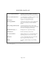
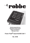
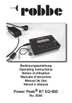
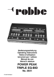
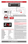
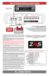
User Manual
Q2 timer
www.4dfx.com.au/DTox
FEATURES of the DTox Q2
Four lever operated functions
Typically Fuel shutoff, Rudder, VIT and D/T
Unused functions (arms) can easily be removed
ESC or second remote Servo
A second channel is available to control a remote
Servo or Electronic Speed Control
RCDT aware
Capable of accepting RCDT input
Fully Programmable
All functions and features can be programmed
using most commonly available PalmPilot
devices
Battery Charge and Protection
On-board charging circuitry enables much
simpler charging options and protects the battery
from both overcharging and discharge.
130mAh LiPo battery ***
Enough power for a typical days flying
LED indicators
Provide visual keys to timer states
0.1 second resolution
timing resolution is 0.1 second and allows for
total timing interval of over 6500 seconds
Dimensions
A cavity 22mm high, 60mm wide and 21mm
deep is required to house the timer
Weight
22 grams, complete flying set-up including
battery
*** See note about international shipping of Lipo batteries in the "What's inside the
box" section (page 4)
Page 2 of 2
The DTox Q2 is an electronically controlled multifunction timer designed as a drop in
replacement for the aging Seelig clockwork timers. It provides four functions arms,
can control a second remote servo and has RCDT capability (RCDT receiver is not
included) . Figures I and II indicate the features of the timer.
Figure I
RESET:
TRIGGER:
ON/OFF:
PROGRAM CHARGE:
LED indicators:
Sets timer to wait state
Starts timing sequence
Pin removal powers up the timer
Program and charge socket
Heart - timer state
Charge - battery charging status
Power - applied external power
Figure II
REMOTE TRIGGER:
SERVO#2:
RDT:
BATTERY:
Duplicates trigger function
Second servo control output
RCDT input
Battery connector
Page 3 of 3
Figure III : Supplied items - What's inside the box
DTox Q2: Timer and 2.5mm x 25mm non-conductive power pin. Do not
replace the pin with any material that is conductive.
Programming Mini-USB at one end, which mates with the connector on the
cable: timer, male DB9 at the other end which mates with the 'Sync'
cable of the Palmpilot.
Battery cable: JST-XH plug and socket, mates with board connector and
battery. If battery other than that listed below is utilised the
cable will have to be modified to accommodate selected
battery terminals.
Battery: If the timer is sent to an address within Australia, you get a
single cell 130mAh LiPo battery. "Parkzone" type with JSTXH connector.
Due to postal regulations concerning Lipo batteries, these
cannot be shipped overseas. You'll have to source them
yourself. The web site has links to at least one source.
Preparation
If the timer is to be used with fewer than 4 functions, the 'unused' arms should be
removed to avoid any possibility of rigging errors. This can be easily done by
removing the hold down plate screws to release the arms, Replace screws firmly, but
don't over tighten which may strip the treads in the epoxy casting.
Connect the battery to the timer using the supplied cable. When the battery is first
connected, or after it has been temporarily disconnected, it may be necessary to apply
a short charge cycle to reset the protection circuitry and allow normal operation to
occur. Should you require to remove the battery at any time, do NOT pull on the cable
wires, apply any force to the actual plug or socket. Battery voltage can be checked via
the programming application, DToxEdit.
Remove the power pin and observe the heartbeat LED and the servo disk for signs of
activity as described in the Operation section below. When the timer enters the ready
state, indicated by the heartbeat flashing every two seconds, connect the programming
cable (and the Palmpilot) and run the configuration software to program the desired
timing.
As shipped, the unit is programmed as follows:
1st arm (engine) released at 4 seconds,
at 5 seconds,
2nd arm (rudder)
3rd arm (VIT)
at 6 seconds,
4th arm (DT)
at 120 seconds.
Configuration data is stored in EEPROM and is retained during power down and
battery removal.
To reset a running timer at any point in time, press the reset button. If the timer is to
be left idle for any great length of time, power off by inserting the on/off pin
.
Page 4 of 4
. A cut-out of 22mm x 60mm is needed to seat the timer and a depth of 21mm from
the back face is required. Positioning of battery, connection of RCDT and/or second
servo may require additional clearances.
Do NOT attempt to supply power via the auxiliary connectors (RCDT or Second
servo/ESC), permanent damage to the timer will result!
Page 5 of 5
Operation
When turned on by the removal of the power pin, the unit will perform some
configuration and hardware checks which take a couple of seconds. During this
initialisation period the heartbeat LED remains lit and the servo disc should move first
to the armed position and back to park again. This is a visual indication that the servo
is alive. Once all internal tests are completed the heartbeat LED should flash once
every 2 seconds indicating the unit is ready for use.
When ready to launch the model, the trigger button should be pressed (and held), the
heartbeat LED will now flash twice per second and the servo disk will advance to the
armed position indicating that the timer is armed and ready. The model can now be
launched, obviously resulting in the release of the trigger button. Once the button is
released, the timing sequence begins, the heartbeat LED now flashes every second
and the servo disk is advanced to release each arm at it's programmed time. Several
seconds after all arms have been released (D/T executed) power to the servo, and
RCDT if used, is removed to conserve battery charge and the flash rate of the
heartbeat LED returns to ready state (once every two seconds).
When the model is recovered, the arms should be re-seated and the reset button
pressed, this will rotate the servo disk to the park position, trapping the arms ready for
re-rigging. Should the arms need to be freed at any time, pressing both the reset and
trigger switches simultaneously will drive the servo disk to the fully open position,
releasing all arms. Do not allow the arms to jam the servo disk as this will result in
excessive battery usage and may damage the servo gear train. If jamming occurs drive
the servo disk to the fully open position as described above and rectify the jamming
issue.
Pressing the reset button at any time will terminate the timing sequence, if initiated,
and return the servo disk to the park position.
Power to the servos is shut down 3 seconds after DT is activated.
The position of the second servo follows the primary servo, although this can be
changed in the programming application.
If the timer is to be left idle for any amount of time during the flying session, you
should consider replacing the power pin to turn the unit off and conserve the battery,
but ALWAYS check the power pin is removed before preparing for the next flight.
Page 6 of 6
Battery charging
Charging of the battery is controlled by an onboard system and does not require a
special LiPo charger. The unit can be attached to a PC using a standard USB cable
with correct connector (mini USB at timer end), any mobile phone charger with a
mini USB connector, any car accessory to USB power source. See Figure V below for
examples. The basic requirement is that whatever charging system is used, it should
have a mini-USB plug to connect to the timer and provide a minimum of 100mA.
Maximum charging rate is set at 200mA. The charger input is reverse polarity
protected, but regardless of the charger used, the voltage applied to the timer should
NEVER exceed 7 volts!
Charging is normally done with the unit turned off, but is still possible while the timer
is active.
When a charge source is connected via the mini-USB connector, the green power
LED is illuminated and the orange charge LED stays illuminated until the charging is
complete. The onboard charging circuitry monitors the battery state and shuts off the
charging when battery voltage reaches 4.2 volts. Additional protection circuitry on the
timer effectively disconnects the battery when an overcharge condition is detected.
This protection circuitry will also disconnect the battery when an over discharge
condition is detected or the battery voltage drops below 2.7volts, preserving battery
life.
Additional capabilities
Provision has been made on the circuit board to connect a remote trigger switch to
allow additional flexibility in positioning the timer and to cater for any launch
techniques/requirements. The additional switch should be a normally open momentary
contact type. Fitting of a remote trigger switch does not disable the primary trigger
switch. The second channel can control a remote servo or an ESC, making control of
an electric powered model possible. NOTE: When connecting the ESC for the first
time, before re-programming the control values, the ESC may drive the motor at
timer power on. Ensure that propeller(s) cannot cause damage to you or other
items. The timer by itself is not suitable for F1Q, as there is no power measurement
and no lock-out once the timing sequence has finished.
Connection to the additional servo and or RCDT is via 3 pin headers. Observe correct
polarity, as indicated in Figure IV, when connecting any addition devices.
Figure IV : Connector polarity
Page 7 of 7
The use of RCDT is selected via the programming interface. If selected, RCDT is
only active when the timer is in the timing phase and when the signal is detected the
servo disk immediately advances to release the D/T arm. There is no requirement to
configure the RCDT input, when the model is launched (and trigger released), the
state of the RCDT line is noted. Any subsequent change of state will cause activation.
Programming
To program the timer, simply connect the Palmpilot via the programming cable while
the timer is in reset mode and start the DToxEdit application. Upon exiting the
application the timer will be reset and ready for use. Do not simply disconnect the
cable from the timer before exiting the application as the timer will be left in the
programming state and not respond to the control buttons. Power cycling the timer
will return it to normal operation if you are doubt.
Use of the programming application is covered in detail in the DToxEdit manual.
Activation time of each of the 4 functions, servo position (including the additional
servo if attached), and usage of any fitted RCDT system are all configurable via the
application. Details of hardware configuration and battery status are also available.
Once programmed, all parameters are stored within the unit and use of the
configuration software is only required to either re-program the unit or check
hardware status. You do not need to program the unit unless you require to change
any of the parameters.
Physical considerations
Avoid immersing the timer in raw fuel! This can lead to swelling of the silicon
membrane in the switches causing unpredictable behaviour. Exhaust residue should
not be allowed to build up on the timer.
The battery should be firmly secured in the model (in a foam jacket possibly) and
protected from possible abrasion due to vibration. Follow normal precautions for LiPo
batteries and do not continue the use of damaged or swollen cells. A fully charged
130ma cell should last a normal days flying.
The keen observer may notice areas on the circuit board which are not populated with
nifty SMD devices. These areas were used for development of an on-board recording
optical tachometer and an altimeter module. Development of the tach. was suspended
due to lack of real usefulness, and development of the altimeter function was
suspended due to discontinued production of the altimeter module by the
manufacturer.
Page 8 of 8
Figure V: Additional requirements (not supplied with timer)
DToxEdit: Timer configuration software which runs on Palmpilot devices and is
used to program the timer. The latest version is always available for
download from www.4fx.com.au/DTox
Palmpilot: All models up to M515 and Vx have been tested and verified as suitable.
Other models with a RS232 interface should be suitable. Models with
only a USB interface are not suitable as the timer is equipped with an
RS232 interface. The 'Sync' cable for the selected Palm device should
have a female DB9 connector which is attached to the supplied
programming cable.
Charger: A charger with a mini-USB plug. Almost all 'wall-wart' phone chargers
with mini-USB outputs are suitable, as well as car accessory types. Even
direct connection to a PC or laptop is possible. Maximum voltage should
not exceed 7 volts.
Battery: Spare battery and battery cable. The battery cable supplied suits
batteries that are compatible with Kyosho, E-flight, Parkzone mini
planes. (See website below for details)
Model: Unless the timer is to be used for decorative purposes only, a flying
model would be a wise investment, together with a pair of mounting
screws.
www.4dfx.com.au/DTox
Page 9 of 9