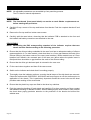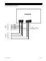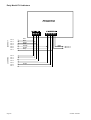
1
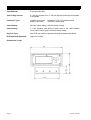
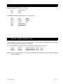
WARNING: Semiconductor devices used in this equipment may be permanently damaged due to electrostatic potentials encountered in routine handling, testing and storage. Antistatic precautions MUST be followed when servicing this product. COPYRIGHT: © 1997-2008 Iconix New Zealand Ltd All rights reserved. No part of this manual may be copied or reproduced in any form or by any means without the prior written consent of Iconix New Zealand Ltd. The information in this manual is subject to change without notice and should not be construed as a commitment by Iconix New Zealand Ltd. Great care has been taken to verify the accuracy of this manual, however Iconix New Zealand Ltd assumes no responsibility for any technical inaccuracies or typographical errors. ICONIX NEW ZEALAND LTD 345 Thames Highway P O Box 220 Oamaru New Zealand Phone 64-3-4372548 Fax 64-3-4372175 CONTENTS SECTION PAGE 1 SPECIFICATIONS.......................................................................................7 2 MECHANICAL..............................................................................................8 3 OPERATING INSTRUCTIONS....................................................................9 Getting Started.......................................................................................9 Weighing Modes....................................................................................9 4 SYSTEM CARE..........................................................................................10 Site Preparation...................................................................................10 5 CONNECTORS..........................................................................................11 6 SCALE BASE SELECTION.......................................................................11 7 SPAN CALIBRATION................................................................................ 12 Restoring Default Calibration...............................................................12 8 SET-UP: GENERAL...................................................................................13 9 SET-UP: AUTORANGING.........................................................................14 10 SERVICING................................................................................................16 11 PCB CONNECTIONS................................................................................17 12 PARTS LIST...............................................................................................19 EEPROM Replacement ......................................................................20 Serial Number Code............................................................................ 20 Firmware Upgrades .............................................................................20 1. SPECIFICATIONS Supply Voltage: Nominal .... 12V DC Maximum .... 19V DC Reverse polarity protection diode fitted. Low Battery Indication: Below 11.4 Volts the LOW BAT pointer s will be on. The FX1 switches off at approximately 10 Volts. Supply Current: Approximately 100 mA including loadbar set. Temperature Range: -5ºC to +50ºC Zero Tracking: Small residual weights left on the scale between weighings (dirt build up) are automatically 'zero-tracked' out and the scale restored to zero. As this occurs the ZERO pointer s will indicate that ZERO has been reached. The zero-tracking amount is set to 0.5% of the weight displayed after the last press of the WEIGH key, with a 2.2 kg maximum. At switch-on the zero-tracking amount is initialised to 0.015% of capacity (0.3 kg for 2000 kg loadbar set). Resolution: SCALE 1 Standard Loadbars Minimum Capacity: SCALE 2 Vet Scale SCALE 3 Heavy-Duty Loadbars Autoranges in graduated steps from the zero point of the scale. Metric Model Resolution 0 - 20 kg 0.1 kg 20 - 50 kg 0.2 kg 50 - 200 kg 0.5 kg 200 - 500 kg 1 kg 500 - 2000 kg 2 kg Imperial Model Resolution 0 - 40 lb 0.2 lb 40 - 100 lb 0.5 lb 100 - 400 lb 1 lb 400 - 1000 lb 2 lb 1000 - 4000 lb 5 lb 20 kg (The 0 - 20kg range is available but is not part of the EMC specification). 0 - 100 kg 100 - 300 kg 0.05 kg 0.1 kg 0 - 100 kg 100 - 200 kg 200 - 1000 kg 1000 - 3000 kg 0.5 kg 1 kg 2 kg 5 kg 0200 - 200 lb 600 lb 0.1 lb 0.2 lb 0 - 200 lb 200 - 400 lb 400 - 2000 lb 2000 - 6000 lb 1 lb 2 lb 5 lb 10 lb Accuracy: ± 0.5% of Displayed Reading ± 1 Division (where 1 division is 0.1kg, 0.5kg etc depending on weight range) RF Immunity: Maximum additional error in a 3V/m RF field in the range 27 500 MHz is : ± 2 divisions for 20 – 50 kg ± 1 division for 50 – 200 kg ± 0 division for 200 – 2000 kg EMC Approvals: Meets or exceeds the following standards: IEC801-2 Electrostatic discharge EM50081-1 Free radiation measurements EM50082-1 RF immunity Note: The EMC Approvals apply to FX1 PCB4401 Version E and later. FX1SM 09Jan08 Page 7 2. MECHANICAL Case Material: Polycarbonate alloy Case Fixing Screws: 9 x self tap screws 6G x ¾ T25 pan square behind top and bottom front decals. Connector Type: Loadbar connectors: Battery connector: Case Sealing: Silicone rubber tubing, silicone grease coated Case Venting: 0.7 mm breather hole drilled in back case or (for older models) 3mm bottom centre gap in silicone rubber tubing. Key Pad Type: Alps PCB tact switches operated through polycarbonate decal Environmental Standard: Approved to IP65 Amphenol 7 Pin C16 chassis socket 3 pin MIC chassis plug Dimensions in mm: Page 8 FX1SM 09Jan08 3. OPERATING INSTRUCTIONS GETTING STARTED Either: Attach the battery cable to the indicator and clip onto a 12V DC battery (car, tractor, battery, etc). ENSURE CORRECT POLARITY: red clip to +, black clip to -. Or: Plug the Iconix AC adaptor (optional accessory) into the indicator for mains powered operation. Connect the two loadbar cables to the loadbar sockets on the underside of the indicator. Press the ON/ZERO key. The scale will automatically return to zero. When complete the ZERO pointer will show that the scale is at zero. NOTE: If a large load (such as a partly filled wool bale in a wool press) remains on the scale from previous use, the last weight will be displayed. The operator can continue the weighing session from where last finished. Alternatively, press ON/ZERO to return the scale to zero. Check that the ZERO pointer is displayed. Load the animal onto the platform. Press the WEIGH key. The animal is accurately weighed and the result locked on the display. Remove the animal from the weighing platform. The last animal’s weight remains locked on the display. Check that the ZERO pointer is displayed between animal weighings. If the ZERO pointer does not appear, hold the next animal back, keep hands etc clear of the crate and press the ZERO key. The scale will return to zero and the weighing session can proceed. At the end of the weighing session, switch the indicator OFF. Disconnect the battery and loadbar cables. ENSURE THAT THE CAPS ARE FIRMLY REPLACED ON THE LOADBAR AND INDICATOR CONNECTORS WEIGHING MODES FREE MODE At switch ON the scale operates in FREE MODE, which is suitable for static load weighing. The display is continuously updated with the weight currently on the scale. The scale can be returned to FREE MODE by pressing the ON/ZERO key, noting that the scale should be empty, since the scale will be zeroed. HOLD MODE A press of the WEIGH key switches the scale to HOLD MODE, which is suitable for live animal weighing. A press of the WEIGH key starts an averaging process which then displays the accurate weight of a moving animal. The weight is locked on the display until the next key press. FX1SM 09Jan08 Page 9 4. SYSTEM CARE The FX1 weighing system has been designed to work reliably for long periods of time under adverse conditions. However like any equipment, common sense and care will assist in keeping it in good operating condition. ESSENTIAL CARE Fit caps to cable ends and indicator sockets when not in use to protect from dirt and moisture. Hang the cable ends up, out of mud and dust. Damage may occur if the capacity of the scale is exceeded. Loadbar cables must be kept in good condition. SITE PREPARATION The choice of weighing site is important for accurate weighing results and ease of use. A well chosen site that is level will ensure the best conditions for accurate weighing. The loadbars must be bolted to the platform or crate and be firmly attached to the ground or concrete pad. Any rocking or twisting of the platform could result in weighing errors. Adequate clearance around the platform is essential. Any binding or rubbing with posts or gates will produce weighing errors. The race bracket is best mounted on a fence or post and not the crate. Mount the indicator in a well lit position for best readability. A well chosen site will help animals flow smoothly through the system. Mounting the indicator away from the crate will help to keep hands free of the crate when the weigh cycle is started. Page 10 FX1SM 09Jan08 5. CONNECTORS POWER CONNECTOR (MIC 3 Pin Male) Pin 1 Pin 2 Pin 3 No Connection DC(+) DC(-) LOADBAR SOCKETS (Amphenol C16 7 Pin Female) Pin 1 Pin 2 Pin 3 Pin 4 Pin 5 Pin 6 Pin 7 6. Ex (-) Black Sig (-) White Sig (+) Green Ex (+) Red Scale Select 1 Scale Select 2 Scale Select 3 SCALE BASE SELECTION At switch ON the indicator automatically configures to a scale capacity determined by the position of wire links in the Amphenol plugs of the loadbars. The scale capacities are factory set to suit standard loadbar types as follows : Scale 1 Scale 2 Scale 3 2000 kg 300 kg 3000 kg Loadbar Plug Link: Pin 4 - Pin 5 Loadbar Plug Link: Pin 4 - Pin 6 Loadbar Plug Link: Pin 4 - Pin 7 Note: Product made to specific order with non-standard scale bases may have different settings from those shown. FX1SM 09Jan08 Page 11 7. SPAN CALIBRATION NOTE: The span calibration procedure is performed independently for each scale (1, 2 and 3). Plug the scale base (loadbars etc) into the indicator. Hold the WEIGH key down, then press the ON/ZERO key, releasing the WEIGH key when ’SEt’ appears. P2.06 SEt 0.0 Display reads (for example) then then after 3 seconds The indicator is now in a state that allows spanning to be performed. With no weight on the scale, zero the scale with the ON/ZERO key. Place the test weight (e.g. 500kg) on the scale, allow a few seconds to settle, then press ON/ZERO and WEIGH simultaneously. NOTE: To ensure that system accuracy is maintained, the test weight should be as close as possible to the maximum working capacity of the scale base. To maintain system accuracy over the full range, the minimum test weight value for a 2000 kg capacity scale base is 500 kg. The display will show ’SPAn’ while weighing the test weight, then display to the nearest kilogram, according to the present calibration. e.g ’0523’. Change the displayed weight to the correct value (in kilograms) using: ON/ZERO WEIGH = Scroll = Scroll One press of a scroll key will increase (or decrease) the weight by 1 kg. For large adjustments to the displayed weight, hold down the required scroll key for more than 1 second, for rapid repeat scrolling. When the displayed reading is the same as the test weight, press no keys for 5 seconds. ’sAUE’ is displayed as the new calibration is stored in EEPROM. NOTE: Having completed the span procedure, the scale should be switched OFF then back ON, and a series of test weights applied to confirm the accuracy of calibration. RESTORING DEFAULT CALIBRATION If problems arise, for example due to attempting to calibrate with no test weight on the scale, and further attempts to calibrate fail, for V2.06 onwards it is possible to return the FX1 to a default calibration point. During calibration, as soon as the message ’Hi’ or ’LO’ appears on the display, press the ZERO key. On return to the normal operating mode, confirm that the FX1 responds when weight is applied to the scale, then repeat the full calibration procedure. Page 12 FX1SM 09Jan08 8. SET-UP: GENERAL NOTE: The set-up parameters detailed below are set independently for each scale (1, 2 and 3). Access to set-up is by holding down the WEIGH key at switch-on, as described in the Span Calibration section. As soon as ’sEt’ is displayed, release the WEIGH key, then press ON/ZERO. The parameters are accessed in the following order: 1. WEIGHT UNITS ’HG’ ’Lb’ for kilograms for pounds To change the setting, use the ON/ZERO key. To accept the displayed setting and step on to the next parameter, press WEIGH. The standard factory setting is kg. If pounds are selected, the scale calibration is changed accordingly. NOTE: In span calibration the Test Weight must ALWAYS be entered in KILOGRAMS, regardless of the weight units setting. 2. ZERO-TRACKING ’2-t.1’ if enabled ’2-t.0’ if disabled To change the setting, use the ON/ZERO key. To accept the displayed setting and step on to the next parameter, press WEIGH. Zero-tracking is a feature which automatically restores the scale to zero, by “tracking out” small amounts of dung and dirt left on the scale. It should be enabled for most weighing applications. 3. DISPLAY RELEASE ’rEL.1’ if enabled ’rEL.O’ if disabled To change the setting, use the ON/ZERO key. To accept the displayed setting and step on to the next parameter, press WEIGH. The standard factory setting is Display Release OFF, which in HOLD mode keeps the last weighing locked on the display, until the next weighing. For Display Release ON, when the animal that has been weighed is moved from the scale, the displayed weight will not remain locked on the display. 4. PERMANENT FREE MODE Version 2.03 firmware onwards ’frE.1’ if enabled ’frE.O’ if disabled To change the setting, use the ON/ZERO key. The standard factory setting is Permanent Free Mode OFF, which puts the indicator into HOLD mode whenever the WEIGH key is pressed, locking the weight on the display. When Permanent Free Mode is ON, the WEIGH key may be pressed, however the indicator will remain in FREE mode. After the Permanent Free Mode has been viewed or modified, WEIGH is pressed for the final time. ’sAuE’ is displayed while the settings are being stored, before returning to the weighing mode. FX1SM 09Jan08 Page 13 9. SET-UP: AUTORANGING It is possible to configure each scale (1, 2 and 3) with up to six weight ranges with associated resolution steps, up to the maximum scale capacity of the scale base. The standard factory settings for the scales are: Step (kg) Scale 1 2000 kg loadbars 0.1 0.2 0.5 1 2 Scale 2 300 kg vet scale 0.05 0.1 Scale 3 3000 kg loadbars 0.5 1 2 5 Range Limit (kg) 19.9 49.8 199.5 499 2200 99.95 400.0 99.5 199 998 3300 WARNING The factory settings of resolution steps and range limits are the result of many years of experience in the live animal weighing industry. The settings provide a compromise between stability, repeatability and the versatility of the scale for weighing different animal types. Changing to finer resolution settings than standard will probably result in unstable and non-repeatable weight readings. The auto-ranging settings allow the FX1 system to be configured for “one off” applications or for the indicator to be used with alternative scale bases. Please contact technical staff at Iconix for advice. PROCEDURE Plug the scale base (loadbars etc) into the indicator. Hold the WEIGH key down, then press the ON/ZERO key, releasing the WEIGH key when ’sEt’ appears. Display reads then then after 3 seconds P2.06 SEt 0.0 Press the ON/ZERO and WEIGH keys simultaneously. Display reads SPAn Immediately ’SPAn’ appears, press the ON/ZERO key. Display reads then (for example) rESn 0.I Press the ON/ZERO key to scroll through the choices of resolution step. Page 14 FX1SM 09Jan08 Press the WEIGH key to store the desired resolution step. The display next shows the first range limit. Display reads then (for example) HI 019.9 To change the Range Limit setting, use: ON/ZERO WEIGH = Scroll = Scroll One press of a scroll key will increase (or decrease) the Range Limit by the resolution step size for this range. For large adjustments to the Range Limit, hold down the required scroll key for more than 1 second, for rapid repeat scrolling. When the range limit setting is correct, press no keys for 5 seconds. Having accepted the new range limit setting, the FX1 now displays the resolution step for the second range. Repeat the steps above to examine and/or modify the resolution step and range limit for each of the required ranges. The number of ranges used in auto-ranging may vary from 1 to 6. When the required number of ranges have been configured, select zero as the value for the resolution step for the next range. Press the WEIGH key to accept this value. The indicator will display ’SAUE’ as it stores the new settings and returns to the normal weighing mode. SINGLE RANGE EXAMPLE To set up the FX1 for a single range of 0 - 2000 kg in 5 kg steps: Enter Autoranging Set-Up as above: Display reads then (for example) rESn 0.5 Set the first resolution step to 5 kg using the ON/ZERO key: 5 Display reads Store resolution step 1 by pressing the WEIGH key: Display reads then (for example) HI 0995 Change Range Limit 1 until it equals the required full scale capacity of 2000 kg, using: ON/ZERO WEIGH Display now reads: = Scroll = Scroll 2000 Press no keys for 5 seconds to accept the new setting. Using the ON/ZERO key, change the setting of the resolution step for range 2, until: Display reads 0 Press the WEIGH key to store the new settings and return to normal weighing: Display reads FX1SM 09Jan08 SAUE Page 15 10. SERVICING NOTE: All adjustable parameters are accessible by front panel key presses. The FX1 has no internal adjustments. DISASSEMBLY NOTE: The front decals (front panel labels) can not be re-used. Obtain a replacement set before starting this procedure. Carefully lift up a corner of the top and bottom front decals. Peel the complete decals off and discard. Remove the five top and four bottom case screws. Carefully split the case halves, observing that the indicator PCB is attached to the front and the loadbar and battery connectors are attached to the rear. REASSEMBLY NOTE: Maintaining the IP65 waterproofing standard of the indicator requires that new decals must be fitted according to the following procedure. Ensure that the silicone tubing embedded in the case front has an adequate coating of silicone grease applied to it. For older models, check that there is a 3 mm gap between the ends of the silicone tubing in the bottom centre of the case (case breather). Newer models have a 0.7mm breather hole drilled in the recessed part of the case rear (above where the plastic insert is fitted) and there should be no gap between the ends of the silicone tubing. Ensure that the silica gel desiccant pack is returned to the case rear. Fit the case halves together and then fit the case screws. Switch on the indicator and check that it is working properly. Thoroughly clean the indicator surfaces, ensuring that all traces of the old decals are removed. Clean the surfaces with ISOPROPYL ALCOHOL and keep fingers etc off the surfaces prior to application of the decals. This is particularly important around the screw holes as the decal provides water sealing of the screw holes. Ensure that the plastic key caps are fitted to the three key switches. Peel the protective backing off each decal and carefully fit in place ensuring no finger contact with adhesive backing or indicator surface. Without damaging the decal surface, firmly smooth the decal down paying particular attention to the perimeter of the decals and around the window area. Page 16 FX1SM 09Jan08 11. PCB CONNECTIONS Loadbar 1 Current Model FX1 Indicators Pin 4 Pin 1 Pin 3 Pin 2 Pin 5 Pin 6 Loadbar 2 Pin 7 Red Black Green White Orange Purple Grey Black Red MIC Pin 3 MIC Pin 2 Pin 4 Pin 1 Pin 3 Pin 2 Pin 5 Pin 6 Pin 7 FX1SM 09Jan08 Page 17 Loadbar 1 Early Model FX1 Indicators Pin 4 Pin 1 Pin 3 Pin 2 Pin 5 Pin 6 Loadbar 2 Pin 7 Pin 4 Pin 1 Pin 3 Pin 2 Pin 5 Pin 6 Pin 7 Page 18 Red Black Green White Orange Purple Grey Black Red MIC Pin 3 MIC Pin 2 Purple FX1SM 09Jan08 12. PARTS LIST Description Iconix Part Number Indicator Assembly Chassis Socket Amphenol Cap Chassis Socket Amphenol Chassis Plug 3 Pin MIC PCB Assembly FX1 27mm LCD Decal FX1-27mm Upper English Decal FX1-27mm Lower English Decal Set FX1 English (3 pcs) – OLD: for 21mm LCD Case Front FX1 + Window, No Decals Case Rear Assembly FX1 complete with Connectors Case Insert Rear FX1 Key Cap - Tact Switch Screw FX1 Case 6G x ¾ Stainless T25 Pan Square 0099407 0116838 0147269 0400538 0400611 0400613 0400581 0400041 0400040 0198568 0159200 0157602 Components on Main PCB IC AT89S52 Microcontroller FX1 Programmed IC AT24C02PC EEPROM IC AY0438/P LCD Driver 0210017 0400051 0195307 (If replacing S4521 with AY0438, change adjacent 4700pF ceramic to 100pF) IC TC765OCPD Op Amp IC TC500CPE A/D Converter LCD Custom 4 Digit 27mm, for PCB4401G and later 0134573 0134658 0400528 (Must be sourced from Iconix NZ Ltd) LCD Custom 4 Digit 21mm (OLD), for PCB4401F and earlier 0198940 (Must be sourced from Iconix NZ Ltd) Accessories Battery Cable Assembly Instruction Card FX1 English Race Bracket FX1 FX1SM 09Jan08 0147375 0208960 0199930 Page 19 EEPROM REPLACEMENT When the FX1 is switched on for the first time after replacement of the EEPROM, the display will normally show ’PPEE’. Press the WEIGH key within 5 seconds of switch-on to programme the EEPROM with default settings for span calibration and set-up parameters. This must be done with the scale base connected. If the indicator is to be used with different scale types, the same procedure must be followed for each. After EEPROM replacement, span calibration must be performed for each scale (1, 2 or 3) used. SERIAL NUMBER CODE Example: where: 6 09 XM01 123 6 09 XM01 123 = = = = Year of Manufacture (2006) Month of Manufacture (September) Model FX1 Serial Number FIRMWARE UPGRADES All generations of FX1 PCBs may be upgraded to the latest firmware. When the microcontroller (0210017) is ordered, it will be supplied with the latest version of the program. Page 20 FX1SM 09Jan08