1
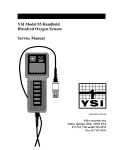
YSI Model 85
Handheld
Oxygen,
Conductivity,
Salinity,
And Temperature
System
Service
CONTENTS
SECTION 1 INTRODUCTION....................................................................................................1
1.1 Service Philosophy ............................................................................................................2
1.2 Specifications .....................................................................................................................2
SECTION 2 PRINCIPLES OF OPERATION .............................................................................5
SECTION 3 SYSTEM SETUP AND OPERATION....................................................................7
3.1 Preparing the DO Probe ...................................................................................................7
3.2 System Calibration............................................................................................................8
3.3 Advanced Conductivity Setup.........................................................................................10
3.4 Making Measurements ..................................................................................................11
3.5 Saving & Recalling Data ................................................................................................13
SECTION 4 TROUBLESHOOTING AND MAINTENANCE.................................................17
4.1 Discussion of Measurement Errors ...............................................................................17
4.2 Probe Maintenance .........................................................................................................19
4.3 System Functionality Test ..............................................................................................21
4.4 Test Procedures ..............................................................................................................22
4.5 Troubleshooting...............................................................................................................25
SECTION 5 SERVICE
5.1 Disassembly Procedures.................................................................................................27
5.2 PCB Assembly Drawings ................................................................................................28
5.3 PCB Components ............................................................................................................29
5.4 Schematic Diagrams .......................................................................................................30
5.5 Exploded View.................................................................................................................32
SECTION 6 WARRANTY AND REPAIR ................................................................................33
Appendix A Accessories and Replacement Parts ......................................................................37
Appendix B Temperature Correction Data ................................................................................39
Appendix C Calibration Values Table.........................................................................................41
ii
SECTION 1
INTRODUCTION
The YSI Model 85 Handheld Salinity, Conductivity, Dissolved Oxygen & Temperature System is a
rugged, microprocessor based, digital meter with an attached YSI combination conductivity and
dissolved oxygen probe.
The YSI Model 85 is designed for use in field, lab, and process control applications as well as for
environmental, aquaculture, and industrial uses. The Model 85 is available with cable lengths of 10, 25,
50 or 100 feet. The body of the probe has been manufactured with stainless steel to add rugged
durability and sinking weight. The probe also utilizes our easy to install cap membranes for measuring
dissolved oxygen.
The YSI Model 85 probe is a non-detachable; combination sensor designed specifically for the YSI
Model 85 Handheld System. The conductivity portion is a four-electrode cell with a cell constant of
5.0/cm ±4%. The dissolved oxygen portion is a polaragraphic clark type sensor.
The Model
85’s microprocessor allows the system to be easily calibrated for dissolved oxygen or conductivity with
the press of a few buttons. Additionally, the microprocessor performs a self-diagnostic routine each
time the instrument is turned on. The self-diagnostic routine provides you with useful information about
the conductivity cell constant and function of the instrument circuitry.
The system simultaneously displays temperature (in °C), along with one of the following parameters:
dissolved oxygen in either mg/L (milligrams per liter) or % air saturation; conductivity; temperature
compensated conductivity; (in µS/cm or mS/cm), and salinity (in parts per thousand {ppt}).
The system requires only a single calibration regardless of which dissolved oxygen display you use. The
calibration of conductivity is not required but is available. A single calibration will adjust the instrument,
regardless if you are reading conductivity or temperature compensated conductivity. You can switch
between all of these parameters with the push of a single key.
Six AA-size alkaline batteries power the instrument. A new set of alkaline batteries will provide
approximately 100 hours of continuous operation. When batteries need to be replaced, the LCD will
display a “LO BAT” message.
Introduction
1.1
Section 1
SERVICE PHILOSOPHY
The YSI Model 85 is sold as a complete dissolved oxygen, conductivity and salinity measuring system
including an attached probe. Most service issues that occur in dissolved oxygen and conductivity
systems are caused by improper maintenance of the probe. For this reason, troubleshooting efforts
should be initially directed at determining the condition and functionality of the probe and cable.
In the event that a service problem is isolated to the meter itself, YSI recommends the replacement of
the entire defective sub-assembly rather than individual components. To lessen down time, YSI
maintains an adequate stock of replacement sub-assemblies.
The recommended method of determining a sub-assemblies condition is by substitution. For example, to
test for a defective probe/cable assembly, substitute the assembly with a known good assembly or a
decade resistance box. If, after testing, the PCB meets the established specifications, the probe/cable
assembly will have to be serviced or replaced.
1.2
SPECIFICATIONS
Operating Environment
Medium: fresh, sea, or polluted water and most other liquid solutions.
Temperature: -5 to +65 °C
Depth: 0 to 10, 0 to 25, 0 to 50, or 0 to 100 feet (depending on cable length)
Storage Temperature: -10 to +50 °C
Material: ABS, Stainless Steel, and other materials
Dimensions:
Height:
Thickness:
Width:
Weight:
Display:
9.5 inches
2.2 inches
3.5 inches max.
1.7 pounds (w/ 10’ cable)
2.3”W x 1.5”L
(24.13 cm)
(5.6 cm)
(8.89 cm)
(.77 kg)
(5.8cm W x 3.8cm L)
Power: 9 VDC -6 AA-size Alkaline Batteries (included)
Approximately 100 hours operation from each new set of batteries
Water Tightness: Meets or exceeds IP65 standards
YSI, Incorporated
85 Service Manual
2
Introduction
Section 1
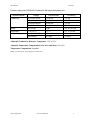
Extensive testing of the YSI Model 85 indicates the following typical performance:
Measurement
Conductivity
Salinity
Temperature
Dissolved Oxygen
Range
0 to 499.9 µS/cm
0 to 4999 µS/cm
0 to 49.99 mS/cm
0 to 200.0 mS/cm
0 to 80 ppt
-5 to +65 °C
0 to 200 % Air Sat.
0 to 20 mg/L
Resolution
0.1 µS/cm
1.0 µS/cm
.01 mS/cm
0.1 mS/cm
.1 ppt
0.1 °C
0.1% Air Saturation
0.01 mg/L
Accuracy
± .5% FS
± .5% FS
± .5% FS
± .5% FS
± 2%, or ± 0.1 ppt
± 0.1 °C (±1 lsd)
± 2% Air Saturation
± 0.3 mg/L
Adjustable Conductivity Reference Temperature: 15°C to 25°C
Adjustable Temperature Compensation Factor for Conductivity: 0% to 4%
Temperature Compensation: Automatic
Range: User selected or Autoranging for Conductivity
YSI, Incorporated
85 Service Manual
3
Introduction
YSI, Incorporated
Section 1
85 Service Manual
4
SECTION 2
PRINCIPLES OF OPERATION
The dissolved oxygen sensor utilizes an oxygen permeable membrane that covers an electrolytic cell
consisting of a gold cathode and a porous silver anode. This membrane acts as a diffusion barrier and
an isolation barrier preventing fouling of the cathode surface by impurities in the environment. Upon
entering the cell through the membrane, oxygen is reduced at an applied potential of -0.8 V referenced
to the silver electrode. The reduction current at the cathode is directly proportional to the partial
pressure of oxygen in liquid (expressed as %-air saturation) which is proportional to the concentration
of dissolved oxygen (in mg/L) at a particular temperature. Thus the same partial pressure of oxygen (%
air-saturation) in liquid gives different concentrations of dissolved oxygen (mg/L) at different
temperatures because of the different solubility’s of oxygen at different temperatures.
The conductivity cell utilizes four pure nickel electrodes for the measurement of solution conductance. Two of the
electrodes are current driven, and two are used to measure the voltage drop. The measured voltage drop is then
converted into a conductance value in milli-Siemens (millimhos). To convert this value to a conductivity (specific
conductance) value in milli-Siemens per cm (mS/cm), the conductance is multiplied by the cell constant that has
units of reciprocal cm (cm -1). The cell constant for the Model 85 conductivity cell is 5.0/cm + 4%. For most
applications, the cell constant is automatically determined (or confirmed) with each deployment of the system
when the calibration procedure is followed. Solutions with conductivity’s of 1.00, 10.0, 50.0, and 100.0 mS/cm,
which have been prepared in accordance with recommendation 56-1981 of the Organization International De
Metrologie Legale (OIML) are available from YSI. The instrument output is in µS/cm or mS/cm for both
conductivity and specific conductance. The multiplication of cell constant times conductance is carried out
automatically by the software.
TEMPERATURES EFFECT ON CONDUCTIVITY
The conductivity of solutions of ionic species is highly dependent on temperature, varying as much as 3% for each
change of one degree Celsius (temperature coefficient = 3%/C). In addition, the temperature coefficient itself
varies with the nature of the ionic species present.
Because the exact composition of a natural media is usually not known, it is best to report conductivity at a
particular temperature, e.g. 20.2 mS/cm at 14 C. However, in many cases, it is also useful to compensate for the
temperature dependence in order to determine at a glance if gross changes are occurring in the ionic content of the
medium over time. For this reason, the Model 85 software also allows the user to output conductivity data in
either raw or temperature compensated form. If "Conductivity" is selected, values of conductivity that are NOT
compensated for temperature are output to the display. If "Specific Conductance" is selected, the Model 85 uses the
temperature and raw conductivity values associated with each determination to generate a specific conductance
value compensated to a user selected reference temperature (see Section 3.3, Advanced Setup) between 15 C and 25
C. Additionally the user can select any temperature coefficient from 0% to 4% (see Section 3.3, Advanced Setup).
Using the Model 85 default reference temperature and temperature coefficient (25 C and
1.91%), the calculation is carried out as in equation (1) below:
Specific Conductance (25 C) = Conductivity
1 + TC * (T - 25)
Principles of Operation
Section 2
As noted above, unless the solution being measured consists of pure KCl in water, this
temperature compensated value will be somewhat inaccurate, but the equation with a value of
TC = 0.0191 will provide a close approximation for solutions of many common salts such as
NaCl and NH4Cl and for seawater.
Salinity is determined automatically from the Model 85 conductivity readings according to algorithms
found in Standard Methods for the Examination of Water and Wastewater (ed. 1989). The use of
the "Practical Salinity Scale" results in values that are unitless, since the measurements are carried out in
reference to the conductivity of standard seawater at 15 C. However, the unitless salinity values are
very close to those determined by the previously-used method where the mass of dissolved salts in a
given mass of water (parts per thousand) was reported. Hence, the designation "ppt" is reported by the
instrument to provide a more conventional output.
For further information on conductivity and the above standard information, refer to the ASTM
document, Standard Methods of Test for Electrical Conductivity of Water and Industrial Wastewater,
ASTM Designation D1125-82, and OIML Recommendation Number 56. ASTM symbols for
conductivity, cell constant, and path lengths differ from those preferred in the general literature and also
from those used in this manual.
YSI, Incorporated
85 Service Manual
6
SECTION 3
3.1
SYSTEM SETUP AND OPERATION
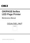
PREPARING THE DO PROBE
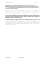
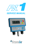
DISSOLVED OXYGEN PROBE PREPARATION
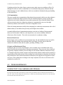
Follow the instructions below to install fresh KCl solution and a new membrane cap.
1.
2.
3.
4.
Unscrew the probe sensor guard.
Remove the old membrane cap.
Thoroughly rinse the sensor tip with distilled water.
Inspect the gold electrode and silver electrodes. If resurfacing is required, refer to Section 4.2, Probe
Maintenance.
5. Prepare the electrolyte according to the directions on the KCl solution bottle.
6. Hold the membrane cap and fill it at least 1/2 full with the electrolyte solution.
7. Screw the membrane cap onto the probe moderately tight. A small amount of
electrolyte
should overflow.
Fill Membrane
C
p KCL Solution
w iat h
Unscrew Cap
Unscrew Guard
Screw Cap on
Screw Guard on
moderately tight
moderately tight
System Setup and Operation
3.2
Section 3
SYSTEM CALIBRATION
CALIBRATION OF DISSOLVED OXYGEN
To accurately calibrate the YSI Model 85 you will need to know the approximate altitude of the region in which you
plan to take your dissolved oxygen measurements.
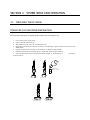
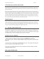
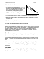
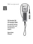
1. Ensure that the sponge inside the
instrument's calibration chamber is wet. Insert
the probe into the calibration chamber.
2. Turn the instrument on by pressing the
ON/OFF button on the front of the instrument.
Press the MODE button until the dissolved
oxygen is displayed in mg/L or %. Wait for the
dissolved oxygen and temperature readings to
stabilize (usually 15 minutes is required).
Calibration/Storage
Chamber
3. Use two fingers to press and release the UP
ARROW and DOWN ARROW buttons at the same time once.
4. The LCD will prompt you to enter the local altitude in hundreds of feet. Use the arrow keys
to increase or decrease the altitude. When the proper altitude appears on the LCD, press the
ENTER button once.
EXAMPLE: Entering the number 12 here indicates 1200 feet.
5. The Model 85 should now display CAL in the lower left of the display, the calibration should be
displayed in the lower right of the display and the actual % should be on the main display. Press the
ENTER button and the display should read SAVE then should return to the Normal Operation Mode.
Each time the Model 85 is turned off, it may be necessary to re-calibrate before taking measurements. All
calibrations should be completed at a temperature which is as close as possible to the sample temperature.
Dissolved oxygen readings are only as good as the calibration.
YSI, Incorporated
85 Service Manual
8
System Setup and Operation
Section 3
CALIBRATION OF CONDUCTIVITY
IMPORTANT: System calibration is rarely required because the YSI Model 85 conductivity cell is typically very
stable. However, after service, it is wise to check the system calibration and make adjustments when necessary.
Prior to calibration, it is important to remember the following:
• Always use clean, properly stored, NIST traceable calibration solutions (see Accessories and Replacement Parts) and
a clean calibration container.
•
Rinse the probe with distilled water (and wipe dry) between changes of calibration solutions.
•
When placed in solution, allow the probe time to stabilize with regard to temperature (approximately 60
seconds) and gently agitate the probe to remove any air bubbles.
•
To minimize error, perform sensor calibration at a temperature as close to 25o C as possible.
To perform an accurate calibration of the YSI Model 85:
1.
Clean the probe thoroughly (see Probe Maintenance)
2.
Place at least 3-4 inches of solution in a clean glass beaker. Select a calibration solution which is most similar
to the sample being measured
•
•
•
For sea water choose a 50mS/cm conductivity standard (YSI Item #3169)
For fresh water choose a 1mS/cm conductivity standard (YSI Item #3167)
For brackish water choose a 10mS/cm conductivity standard (YSI Catalog # 3168)
3.
Turn the instrument on. Use the MODE button to advance the instrument to display conductivity
4.
Insert the probe into the beaker deep enough to cover the entire probe. Do not rest the probe on the bottom of
the container -- suspend it above the bottom at least 1/4 inch.
5.
Allow at least 60 seconds for the temperature reading to become stable
6.
Move the probe vigorously from side to side to dislodge any air bubbles from the electrodes
7.
Press and release the UP ARROW and DOWN ARROW buttons at the same time. The CAL symbol will appear
at the bottom left of the display to indicate that the instrument is now in Calibration mode.
Use the up or down arrow key to adjust the reading on the display until it matches the value of the calibration
solution you are using. Once the display reads the exact value of the calibration solution being used (the
instrument will make the appropriate compensation for temperature variation from 25o C) press the ENTER
button once. The word “SAVE” will flash across the display for a second indicating that the calibration has
been accepted.
8.
Note: The YSI Model 85 is designed to retain its last conductivity calibration permanently.
Therefore, there is no need to calibrate the instrument after battery changes or power
YSI, Incorporated
85 Service Manual
down.
9
System Setup and Operation
3.3
Section 3
ADVANCED CONDUCTIVITY SETUP
The default reference temperature and temperature coefficient setting of the Model 85 are appropriate for the vast
majority of measurement applications. However, it is important that the service technician understand that the
user may have modified these settings and will affect temperature compensated measurements.
IMPORTANT: There is never a need to enter Advanced Setup Mode unless there is a need for a change in the
reference temperature and or the temperature coefficient. Therefore, unless you are certain that an application
requires a change to one or both of these criteria, do not modify the default reference temperature (25oC) or the
default temperature coefficient (1.91%).
CHANGING THE TEMPERATURE COEFFICIENT
1.
Turn the instrument on, and wait for it to complete its self test procedure
2.
Use the MODE button to advance the instrument to display conductivity.
3.
Press and release the DOWN ARROW and the MODE buttons at the same time. The CAL symbol will appear at
the bottom left of the display
4.
The large portion of the display will show 1.91 % (or a value set previously using Advanced Setup)
5.
Use the Up or Down arrow keys to change the value to the desired new temperature coefficient
6.
Press the ENTER button. The word “SAVE” will flash across the display for a second to indicate that your
change has been accepted
7.
Press the MODE button to return to normal operation; the CAL symbol will disappear from the display.
CHANGING THE REFERENCE TEMPERATURE
1.
Turn the instrument on, and wait for it to complete its self test procedure
2.
Use the MODE button to advance the instrument to display conductivity.
3.
Press and release the DOWN ARROW and the MODE button at the same time.
4.
The CAL symbol will appear at the bottom left of the display
5.
The large portion of the display will show 1.91 % (or a value set previously using Advanced Setup)
6.
Press and release the MODE button; the large portion of the display will show 25.0C (or a value set previously
using the Advanced Setup)
7.
Use the UP or Down arrow keys to change the value to the desired new reference temperature (any value
between 15 oC and 25 oC is acceptable)
8.
Press the ENTER button. The word “SAVE” will flash across the display for a second to indicate that your
change has been accepted
9.
The instrument will automatically return to normal operation mode.
CHANGING FROM AUTORANGING TO MANUAL RANGING
YSI, Incorporated
85 Service Manual
10
System Setup and Operation
Section 3
If your application is easier to perform using a manual range that you select, the YSI Model 85 allows you to turn
off the default autoranging feature. While you are making conductivity or temperature compensated conductivity
measurements simply press and release the UP ARROW button. Each additional press of the UP ARROW button
will cycle the Model 85 to a different manual range until you return again to autoranging. Five pushes of the UP
ARROW button will cycle the Model 85 through the four manual ranges and return the instrument to autoranging.
NOTE: You may see an error message in some manual ranges if the manual range selected is not adequate for the
sample you are measuring. If this happens, simply press and release the UP ARROW button again until a range is
selected which is suitable for your sample. If you get lost and don’t know if you’re in a manual range or
autoranging, simply turn the instrument off and back on. Also note that the conductivity units will flash while you
are in manual range. The instrument will always default to autoranging when first turned on.
The four ranges of the YSI Model 85 are:
Range 1
0 to 499.9 µS/cm
3.4
Range 2
0 to 4999 µS/cm
Range 3
0 to 49.99 mS/cm
Range 4
0 to 200.0 mS/cm
MAKING MEASUREMENTS
TURNING THE INSTRUMENT ON
Once the batteries are installed correctly, turn the instrument face up and press the ON/OFF button. The instrument
will activate all segments of the display for a few seconds, which will be followed by a self-test procedure that will
last for several more seconds. During this power on self-test sequence, the instrument’s microprocessor is
verifying that the instrument is working properly. The Model 85 will display the cell constant of the conductivity
probe when the self-test is complete. If the instrument were to detect an internal problem, the display would show
a continuous error message on the display. You can discover the meaning of these error messages by referring to
Section 4.5, Troubleshooting.
YSI, Incorporated
85 Service Manual
11
System Setup and Operation
Section 3
THE MEASUREMENT MODES OF THE MODEL 85
The Model 85 is designed to provide six distinct measurements:
Ø
Ø
Dissolved Oxygen % -- A measurement of oxygen in percent of saturation.
Ø
Conductivity -- A measurement of the conductive material in the liquid sample without regard to temperature
Ø
Specific Conductance -- Also known as temperature compensated conductivity which automatically adjusts the
Dissolved Oxygen mg/L -- A measurement of oxygen in mg/L
reading to a calculated value which would have been read if the sample had been at 25o C (or some other
reference temperature which you choose). See Advanced Setup .
Ø
Temperature -- which is always displayed.
Ø
Salinity -- A calculation done by the instrument electronics, based upon the conductivity and
temperature readings.
NOTE: When you turn the Model 85 off, it will “remember” which mode you used last and will return to that
mode the next time the instrument is turned on.
To choose one of the measurement modes above (temperature is always displayed) simply press and release the
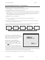
MODE button. Carefully observe the small legends at the far right side of the LCD.
Dissolved Oxygen
in % with°C
Dissolved Oxygen
in mg/L with °C
Conductivity with
°C
If the instrument is reading Specific Conductance the
large numbers on the display will be followed by either
a µ S or an mS. Additionally the small portion of the
display will show the o C flashing on and off.
Specific
Conductance
with °C
Salinity with °C
300.1 µ S
If the instrument is reading Conductivity (not
temperature compensated) the large numbers on the
display will be followed by either a µ S or an mS.
Additionally the small portion of the display will show
the o C NOT flashing.
23.4
o
C
If the instrument is reading Dissolved Oxygen the large
numbers on either a mg/L or % will follow the display.
It is important to remember that the dissolved oxygen probe is stirring dependent. This is due to the consumption
of oxygen at the sensor tip during measurement. When taking dissolved oxygen measurements the probe must be
moved through the sample at a rate of 1 foot per second to provide adequate stirring.
If the instrument is reading Salinity the large numbers on the display will be followed by a ppt.
YSI, Incorporated
85 Service Manual
12
System Setup and Operation
Section 3
AUTORANGING & RANGE SEARCHING
The YSI Model 85 is an autoranging instrument. This means that regardless of the conductivity or salinity of the
solution (within the specifications of the instrument) all you need to do to get the most accurate reading is to put
the probe in the sample.
When you first place the Model 85 probe into a sample or calibration solution, and again when you first remove
the probe the instrument will go into a range search mode that may take as long as 5 seconds. During some range
searches the instrument display will flash rANG to indicate its movement from one range to another. The length
of the range search depends on the number of ranges that must be searched in order to find the correct range for
the sample. During the range search, the instrument will appear to freeze on a given reading for a few seconds
then, once the range is located, will pinpoint the exact reading on the display. The display may also switch to 00.0
for a second or two during a range search before it selects the proper range.
THE BACKLIGHT
At times it may be necessary to take measurements with the Model 85 in dark or poorly lit areas. To help in this
situation, the Model 85 comes equipped with a backlight that will illuminate the display so that it can be easily
read. To activate the backlight, press and hold the LIGHT button. The display will remain lit as long as the button
is depressed. When you let it up, the light goes out to preserve battery life.
3.5
SAVING & RECALLING DATA
The Model 85 is equipped with a non-volatile memory that is capable of storing up to 50 different sets
of readings. Non-volatile memory will retain data even if power is lost. The Model 85 will also assign a
site identity number to each set of readings to allow easy review of the data.
SAVING DATA TO MEMORY
1. While any parameter is displayed on the screen depress the ENTER button and hold for
approximately 2 seconds. The meter will flash SAVE on the display along with the current site identity
being used.
2. When all 50 sites are full the display will flash FULL on the screen. This message will remain on the
screen (even after power down) until a button is pushed.
Once you have acknowledged the memory is full, any subsequent saved data will begin overwriting
existing data starting with site #1.
RECALLING STORED DATA
YSI, Incorporated
85 Service Manual
13
System Setup and Operation
Section 3
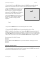
1. To put the Model 85 into the RECALL mode depress the MODE button repeatedly until rcl is
displayed on the screen along with the site ID number in the lower right corner (See figure 1).
2. Depress the ENTER button to review the last set of
data that was saved. The Model 85 will display the
dissolved oxygen in % saturation and temperature.
Another press of the ENTER button will display the
dissolved oxygen in mg/L and the temperature.
rcl
Depress the ENTER button again and again to review
the conductivity, specific conductivity and salinity
readings. All of which are displayed with the
temperature.
01
Figure 1
3. Depress the UP ARROW button to increment through the saved sets of data.
4. Depress the DOWN ARROW button to decrement through the saved sets of data.
NOTE: The Model 85 will recall data as a list. When the UP ARROW is depressed the Model 85
will display the Site ID# for the previously recorded date. For example: If you are reviewing Site ID# 5
and the UP ARROW is depressed the Model 85 will display Site ID# 4. If you are reviewing Site ID#
5 and Site ID# 5 was the last set of data stored the DOWN ARROW button will display Site ID# 1.
Here is an example of the Model 85 memory.
Site ID #1
Site ID #2
Site ID #3
If the UP ARROW button was pressed the Model 85 would display Site ID #2
Site ID #4
Site ID #5
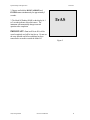
ERASING STORED DATA
1. To erase the data that is stored into the Model 85’s memory, depress the MODE button repeatedly
until the Model 85 displays ErAS on the screen (See figure 2).
YSI, Incorporated
85 Service Manual
14
System Setup and Operation
Section 3
2. Depress and hold the DOWN ARROW and
ENTER buttons simultaneously for approximately 5
seconds.
3. The Model 85 flashing DONE on the display for 1
to 2 seconds indicates successful erasure. The
instrument will automatically change to normal
operation after completion.
ErAS
IMPORTANT: Data in all 50 site ID’s will be
erased completely and will be lost forever. Do not use
the erase function until all recorded data has been
transcribed to an archive outside the Model 85.
Figure 2
YSI, Incorporated
85 Service Manual
15
System Setup and Operation
YSI, Incorporated
Section 3
85 Service Manual
16
SECTION 4
4.1
TROUBLESHOOTING AND MAINTENANCE
DISCUSSION OF MEASUREMENT ERRORS
DISSOLVED OXYGEN MEASUREMENT ERRORS
There are three basic types of error. Type 1 errors are related to limitations of instrument design and
tolerances of instrument components. These are chiefly the meter linearity and the resistor tolerances.
Type 2 errors are due to basic probe accuracy tolerances, chiefly background signal, probe linearity,
and variations in membrane temperature coefficient. Type 3 errors are related to the operator's ability
to determine the conditions at the time of calibration. If calibration is performed against more accurately
known conditions, type 3 errors are appropriately reduced.
The sample calculations that follow are for a near extreme set of conditions.
TYPE 1 ERRORS
A. Meter linearity error: ±1% of full scale reading, or ±0.15 mg/l
B. Component and circuitry error: ±0.05 mg/l
TYPE 2 ERRORS
A. Temperature compensation for membrane temperature coefficient: ±0.03 mg/l
B. Temperature measurement errors: A maximum ±0.2oC probe error is equal to ±0.14 mg/l
TYPE 3 ERRORS
A. Altitude:
A 1000-foot change in altitude is equal to an error of approximately 3% at the 10 mg/l
level.
B. Humidity:
Errors occur if calibration is performed at less than 100% humidity. The error varies
with the temperature as follows:
TEMPERATURE
ERROR
o
0C
0.02 mg/l
o
10 C
0.05 mg/l
20oC
0.12 mg/l
30oC
0.27 mg/l
40oC
0.68 mg/l
Troubleshooting and Maintenance
Section 4
APPROXIMATING THE ERROR
It is unlikely that the actual error in any measurement will be the maximum possible error. A better error
approximation is obtained using a root mean squared (r.m.s.) calculation:
r.m.s. Error = ±[1a2 + 1b2 + 2a2 + 2b2 + 3a2 + 3b2]½ mg/l
CONDUCTIVITY MEASUREMENT ERRORS
System accuracy for conductivity measurements is equal to the sum of the errors contributed by the
environment and the various components of the measurement setup. These include:
⋅ Instrument accuracy
⋅ Cell-constant error
⋅ Solution temperature offset
⋅ Cell contamination (including air bubbles)
⋅ Electrical noise
⋅ Galvanic effects
Only the first three are of major concern for typical measurements, although the user should also be
careful to see that cells are clean and maintained in good condition at all times.
Instrument Accuracy = ± .5% maximum
The accuracy specified for the range being used is the worst case instrument error.
Cell-Constant Error = ± .5% maximum
Although YSI cells are warranted to be accurate to within one percent, you should still determine the
exact cell constant of your particular cell. Contamination or physical damage to the cell can alter the cell
constant. Performing a calibration will eliminate any error that might arise because of cell constant
change.
YSI cells are calibrated to within one percent of the stated cell constant at a single point. We consider
these products to be usefully linear over most instrument ranges. The cell constant can be calibrated to
±0.35% accuracy with YSI conductivity calibrator solutions.
Temperature Error = ± 1% maximum
The solution temperature error is the product of the temperature coefficient and the temperature offset
from 25 C, expressed as a percentage of the reading that would have been obtained at 25 C. The
error is not necessarily a linear function of temperature. The statement of error is derived from a 25 C
temperature offset and a 3%/ C temperature coefficient.
Total Error
YSI, Incorporated
85 Service Manual
18
Troubleshooting and Maintenance
Section 4
Considering only the above three factors, system accuracy under worst case conditions will be ±2%,
although the actual error will be considerably less if recommended and properly calibrated cells and
instrument ranges are used. Additional errors, which can essentially be eliminated with proper handling,
are described below.
Cell Contamination
This error is usually due to contamination of the solution being measured, which occurs when solution is
carried-over from the last solution measured. Thus, the instrument might be correctly reporting the
conductivity seen, but the reading does not accurately represent the value of the bulk solution. Errors
will be most serious when low conductivity solutions are contaminated by carry-over from high
conductivity solutions, and can then be of an order of magnitude or more.
Follow the cleaning instructions carefully before attempting low conductivity measurements with a cell of
unknown history or one that has been previously used in higher value solutions.
An entirely different form of contamination sometimes occurs due to a buildup of foreign material
directly on cell electrodes. While rare, such deposits have, on occasion, markedly reduced the
effectiveness of the electrodes. The result is an erroneously low conductance reading.
Electrical-Noise Errors
Electrical noise can be a problem in any measurement range, but will contribute the most error and be
the most difficult to eliminate when operating in the lowest ranges. The noise may be either lineconducted or radiated or both, and may require, grounding, shielding, or both.
Galvanic and Miscellaneous Effects
In addition to the error sources described above, there is another class of contributors that can be
ignored for all but the most meticulous of laboratory measurements. These errors are always small and
are generally completely masked by the error budget for cell-constant calibration, instrument accuracy,
etc. Examples range from parasitic reactances associated with the solution container and its proximity to
external objects to the minor galvanic effects resulting from oxide formation or deposition on electrodes.
Only trial and error in the actual measurement environment can be suggested as an approach to reduce
such errors. If the reading does not change as the setup is adjusted, errors due to such factors can be
considered too small to see.
4.2
PROBE MAINTENANCE
CONDUCTIVITY CELL CLEANING AND STORAGE
The single most important requirement for accurate and reproducible results in conductivity measurement is a
clean cell. A dirty cell will change the conductivity of a solution by contaminating it. When in use, the cell should
be rinsed with clean water after each use.
YSI, Incorporated
85 Service Manual
19
Troubleshooting and Maintenance
Section 4
To clean the conductivity cell:
1. Dip the cell in cleaning solution and agitate for two to three
minutes. Any one of the foaming acid tile cleaners, such as
Dow Chemical Bathroom Cleaner, will clean the cell
adequately. When a stronger cleaning preparation is
required, use a solution of 1:1 isopropyl alcohol and 10N
HCl. Remove the cell from the cleaning solution.
2. Use the nylon brush (supplied) to dislodge any contaminants from inside the electrode chamber.
3. Repeat steps one and two until the cell is completely clean. Rinse the cell thoroughly in deionized,
or clean tap water.
4. Store the conductivity cell in the meter storage chamber.
OXYGEN PROBE MAINTENANCE AND STORAGE
Membrane life depends on usage. Membranes will last a long time if installed properly and treated with
care. Erratic readings can be a result of loose, wrinkled, damaged, or fouled membranes, or from large
(more than 1/8" diameter) bubbles in the electrolyte reservoir. If erratic readings or evidence of
membrane damage occurs, you should replace the membrane and the KCl solution. The average
replacement interval is two to four weeks.
Precautions
If the membrane is coated with oxygen consuming (e.g. bacteria) or oxygen evolving organisms (e.g.
algae), erroneous readings may occur.
Chlorine, sulfur dioxide, nitric oxide, and nitrous oxide can affect readings by behaving like oxygen at
the probe. If you suspect erroneous readings, it may be necessary to determine if these gases are the
cause.
Avoid any environment that contains substances that may attack the probe materials. Some of these
substances are concentrated acids, caustics, and strong solvents. The probe materials that come in
contact with the sample include FEP Teflon, stainless steel, epoxy, polyetherimide and the polyurethane
cable covering.
Maintenance
Probes that have been exposed to hydrogen sulfide or sulfur dioxide for extended periods may cease
operating in a normal mode. Output current will decrease and may become unstable. Visual symptoms
include blackening of the silver anode and/or discoloration of the gold cathode.
YSI, Incorporated
85 Service Manual
20
Troubleshooting and Maintenance
Section 4
Electrode Cleaning
Model 85 dissolved oxygen probes should be cleaned only when erratic readings occur or after about
every 500 hours of use (two months). Each cleaning removes material and reduces the life of the probe,
so excessive cleaning should be avoided.
Gold Cathode
For correct probe operation, the gold cathode must be textured properly. It can become tarnished or
plated with silver after extended use. Using the adhesive backed sanding disc provided in the 5906
Membrane Kit can clean the gold cathode. Stick the disc to a small flat object, like a bottle cap, then
sand the gold with a twisting motion about 3 times or until all silver deposits are removed and the gold
appears to have a matte finish. If the cathode remains tarnished, return the probe for service.
Silver Anode
It is normal for a dark layer of silver chloride to cover the silver anode. After prolonged use it may
become necessary to clean the anode. Soak the probe in a 14% ammonium hydroxide solution for 2 to
3 minutes or overnight in a 3% ammonium hydroxide solution. Rinse with deionized water, recharge
with electrolyte, and install a new membrane.
4.3
SYSTEM FUNCTIONALITY TEST
OXYGEN
Functionality of the Model 85’s oxygen system can easily be tested using the following procedure.
1. If necessary, service the probe’s electrodes. Follow the instructions in the Maintenance Section.
2. Install a fresh membrane and KCl solution.
3. Place the probe in its calibration chamber.
4. Turn the system on and allow it to stabilize for 30 minutes.
5. Calibrate the system as described in the Calibration Section of this manual.
6. With the probe in the calibration chamber, check the displayed reading for stability. Erratic or
drifting readings indicates a possible problem. See the Troubleshooting Section for help.
7. Place the probe in a zero oxygen environment. The display should decrease rapidly and reach 0
±2.0% in 5 minutes or less.
Note: A zero oxygen environment can be obtain by taking a reading in pure nitrogen gas, in a sodium
sulfite solution, or in a BOD bottle filled with 350 ml of distilled water in which 3 to 7 grams of active
dry yeast has been dissolved and allowed to consume the oxygen (about 5 minutes).
YSI, Incorporated
85 Service Manual
21
Troubleshooting and Maintenance
Section 4
CONDUCTIVITY
Functionality of the Model’s 85 conductivity system can be tested using the following procedure:
1. If necessary, service the probe’s electrodes. See Section 4, Troubleshooting and Maintenance.
2. Verify that the Temperature Coefficient and Reference Temperature are properly set.
3. Use clean, properly stored, NIST traceable, calibration solutions to very the accuracy of the
system. See Section 3.2, System Calibration for procedures.
TEMPERATURE
Compare the 85’s measured temperature value to that of a known traceable temperature standard.
4.4
TEST PROCEDURES
As stated in the Section 1.1, Service Philosophy of this manual, the best way to troubleshoot the Model 85 is by
substitution. Below are procedures to test the accuracy and function of the instrument’s circuits and probe. If any
section of the tests fail the board assembly or probe will have to be repaired or replaced. When disassembled,
connecting a jumper wire to the DGNG pin of JP3 and momentarily touching the desired pin or pins can simulate
the instrument’s keypad functions.
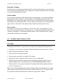
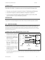
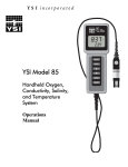
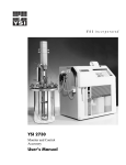
CONDUCTIVITY AND TEMPERATURE CIRCUIT TEST
1.
2.
3.
4.
Disassemble the instrument case by
referring to Section 5.1, Disassembly
Procedures section of this manual.
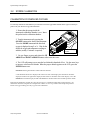
Once the 85 probe is unplugged from
PCB connector JP1, connect a decade
resistance box in its place. Reference
Figure 1 and Figure 2.
Use either a second decade resistance
box or a 10K-ohm resistor to
substitute for the thermistor, RT1 and
RT2. This resistance must be
substituted or an error we displayed
on the LCD.
Using Section 3.2, System Calibration
procedure (start at step 7), calibrate to
1uF
Drive 1
1
Sense 1
2
Sense 2
3
JP1
1uF
Drive 2
4
RT 1
5
R1
10KΩ
RT 2
6
Model 85
µ S using inputs of 11.11 KΩ at
R1 and 10.00 KΩ at R2.
450.0
5.
Decade
Resistance
Box
R2
Test Cable
Probe
Simulators
Figure 1
Use the charts below to test the instrument’s accuracy. Also, check the cell constant by cycling the instrument
on an off. It should fall between K = 4.90 and 5.10. In chart 1, the tolerance column reflects the accuracy of the
decade resistance box.
YSI, Incorporated
85 Service Manual
22
Troubleshooting and Maintenance
Section 4
Conductivity Test (Chart 1)
R1 Resistance R2 Resistance
33.330 Ω
10.00 KΩ ±.1%
111.10 Ω
10.00 KΩ ±.1%
1111.0 Ω
10.00 KΩ ±.1%
11.11 KΩ
10.00 KΩ ±.1%
Decade Tolerance
0.5%
0.2%
0.1%
0.1%
Nominal Reading
150.0 mS
45.00 mS
4.500 mS
450.0 µS
Acceptable Reading
147.2 to 152.8 mS
44.37 to 45.65 mS
4442 to 4560 µS
450.0 µS
Note: After the above procedure is used it will be necessary to recalibrate the system. See System
Calibration.
Temperature Test
R2 Resistance
32.66 KΩ ± .1%
19.90 KΩ ± .1%
10.00 KΩ ± .1%
5329 Ω ± .1%
1752 Ω ± .1%
(Chart 2)
Nominal Reading
0.0 oC
10.0 oC
25.0 oC
40.0 oC
70.0 oC
Acceptable Reading
0.0 ± .1 oC
10.0 ± .1 oC
25.0 ± .1 oC
40.0 ± .1 oC
70.0 ± .1 oC
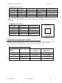
Pin-out JP1
S1
S2 RT2
• • •
• • •
D1 D2 RT1
PCB End (Bottom)
Figure 2
DISSOLVED OXYGEN CIRCUIT TEST
Perform this test using a YSI 16423 Oxygen Test Box or by inputting the resistance values in column 2. To begin the
test, input the resistance value in Row #1, or set the test box to A-2, and calibrate the 100.0 %. If using the
resistances from column 2, maintain the temperature at 10.0 oC (from Chart 2, above).
Input to connector J6, Pins 1 &2
Set 16423 Test
Box to:
Resistor input:
Display Reading
Display Reading
(% Mode)
(Mg/L Mode)
A-2
88.2k Ω ±0.1%
100.0 ±0.1%
11.28 ±0.02 Mg/L
B-2
111.42k Ω ±0.1%
79.1 ±0.2%
8.92 ±0.02 Mg/L
C-2
250.0k Ω ±0.1%
35.3 ±0.2%
3.97 ±0.02 Mg/L
D-2
Infinity
0.0 +1.0%
0.00 ±0.1 Mg/L
YSI, Incorporated
85 Service Manual
23
Troubleshooting and Maintenance
Section 4
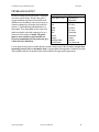
PROBE LEAKAGE TEST
Electrical leakage between the probe’s electrodes
can cause system failures. Remove the probe’s
oxygen membrane and rinse the electrodes with
distilled water. In addition, it may be necessary to
clean the conductivity electrodes as described in
Section 4, Troubleshooting and Maintenance of
this manual. Then, thoroughly dry the sensor end,
inside and outside, and with compressed air or a
soft towel before testing. Caution: The probe
must be clean and dry to perform this test.
External contamination of the probe may give
a false defective indication.
Model 85 Probe Wiring Chart
Probe Wire Color
Electrode or
Thermistor
Green
S1 Sense
Red
D1 Drive
White
D2 Drive
Black
S2 Sense
Blue
Thermistor
Brown
Thermistor
Orange
Anode
Shielded White
Cathode
Shield (Drain)
No connection
Use the probe wiring chart to confirm that the resistance between all of the electrodes (except when
measuring between the two thermistor leads ) is greater than 200 megaohms. Continuity less than
200 megaohm indicates an internal electrical short which will require probe replacement.
YSI, Incorporated
85 Service Manual
24
Troubleshooting and Maintenance
4.5
Section 4
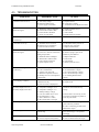
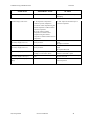
TROUBLESHOOTING
SYMPTOM
POSSIBLE CAUSE
ACTION
1. Instrument will not turn on
A. Low battery voltage
B. Batteries installed wrong
C. Power supply circuit defect
A. Replace batteries
B. Check battery polarity
C. Troubleshoot circuit-Replace PC board
2. Instrument will not calibrate
(Dissolved Oxygen)
A. Membrane is fouled or damaged
B. Probe anode is fouled or dark
C. Probe cathode is tarnished
D. Circuit or probe failure
A. Replace membrane & KCl
B. Clean anode
C. Clean cathode
D. Replace defective assembly
3. Instrument will not calibrate
A. Cell is contaminated
A. See “Maintenance” Chapter
4. Instrument "locks up"
A. Instrument has rec'd a shock
B. Batteries are low or damaged
C. Defective main PC board
A & B. Remove battery lid, wait 15
seconds for reset, replace lid
C. Replace main PC board
5. Instrument readings are inaccurate
(Dissolved Oxygen)
A. Cal altitude is incorrect
B. Probe not in 100% O2 saturated air
during Cal procedure
C. Membrane fouled or damaged
D. Probe anode is fouled or dark
E. Probe cathode is tarnished
F. System requires service
A. Recalibrate w/correct value
B. Moisten sponge & place in Cal
chamber w/ probe & Recal
C. Replace membrane
D. Clean anode
E. Clean cathode
F. Return system for service
6. Instrument readings are inaccurate
(Conductivity)
A. Calibration is required
B. Cell is contaminated
C. Tempco is set incorrectly
D. Reference temperature incorrect
E. Readings are or are not temperature
compensated
A. Batteries are defective or have been
installed incorrectly.
B. Defective main or display PCB
A. Conductivity reading is >200 mS
B. Temperature reading is >95°C
C. Temperature reading is <-5°C
D. Salinity reading is >80 ppt
E. User cell constant cal K is >5.25
F. DO temperature is >46°C
G. DO % saturation is >200%
H. DO concentration is >20 mg/L
A. User cell constant cal K is <4.8
A. See “Calibration” Chapter
B. See “Maintenance” Chapter
C. See “Advanced Setup” Chapter
D. See “Advanced Setup” Chapter
E. See “Making Measurements”
Chapter
A. Replace batteries
B. Replace PCB
(Conductivity)
7. LCD displays "LO BAT"
8. Main Display reads “OVEr”
(Secondary display reads “ovr”)
(Secondary display readn “udr”)
9. Main display reads “Undr”
10. Main display reads “rErr”
A. Reading exceeds user selected
manual range.
11. Main display reads “PErr”
A. User cell constant cal K is 0.0
B. Incorrect sequence of keystrokes.
YSI, Incorporated
85 Service Manual
In all cases, check calibration values and
procedures; check advanced setup
settings.
If each of these is set correctly, see the
Test chapter to determine if problem is
circuit or probe related.
A. Recalibrate instrument using known
good conductivity standard.
B. Follow cell cleaning procedure in the
Maintenance chapter.
A. Use the mode key to select a higher or
lower manual range, or set system to
autoranging.
A. See “Advanced Setup” chapter.
B. Refer to manual section for step by
25
Troubleshooting and Maintenance
SYMPTOM
Section 4
POSSIBLE CAUSE
ACTION
step instruction for the function you are
attempting.
12. Main display reads “LErr”
13. Main display reads “Err”
(Secondary display reads “ra”)
A. In temperature compensated
conductivity mode; temperature
exceeds the values computed using user
defined temperature coefficient and/or
reference temperature.
B. In cell constant cal mode,
temperature exceeds the values
computed using user defined
temperature coefficient and/or reference
temperature.
A. System has failed its RAM test
check procedure.
14. Main display reads “Err”
(Secondary display reads “ro”)
A. System has failed its ROM test
check procedure.
15. Secondary display reads “rEr”
A. Temperature jumper is set to °F and
reading is >199.9°F but <203°F.
A. EEPROM has failed to respond in
time.
A. Meter is in recall mode.
16. Main display reads “FAIL”
(Secondary display reads “eep”)
17. Readings on main display don’t
change
YSI, Incorporated
85 Service Manual
A. & B. Adjust user defined tempco or
reference temperature.
A. Turn instrument OFF and back ON
again.
B. Replace main PCB
A.Turn instrument OFF and back ON
again.
B. Replace Main PCB
A. Troubleshoot temperature circuit.
Defective main PCB or probe
A. Reset by removing batteries and retry.
Replace main PCB.
A. Press MODE button to return to
Normal Operation
26
SECTION 5
5.1
SERVICE
DISASSEMBLY PROCEDURES
Refer to the Assembly drawing on the next page before attempting to disassemble the meter case.
Follow these steps to disassemble the meter case:
STEP 1 -- Place the instrument face down on a flat cloth-covered surface. Use a Phillips screwdriver
to completely remove the screw located at the bottom of the hand strap.
STEP 2 -- Using a standard screwdriver or a small coin, loosen the battery lid screw and remove the
battery lid and all six AA-size batteries.
STEP 3 -- With the instrument face down on the flat, cloth-covered surface, place two fingers into the
battery chamber and your other hand over the cable strain-relief. Pull straight up on the battery
chamber to separate the case halves. Unplug the power connector from the PC Board.
NOTE: Because the Model 85 is water tight, the case halves will be relatively difficult to
separate.
STEP 4 -- The main PC Board is held in place by a single Phillips screw located in the center of the
board. Remove the screw, and gently pull the PC Board away from the front case.
NOTE: The leads on the cable that connect to the main PC Board are quite short. Be careful
not to damage the terminal connectors when you pull the PC Board away from the front case.
STEP 5 -- Carefully slide the probe cable terminal connector out of its mating connector. Make note of
the wire color configuration so that the connectors can be correctly re-installed later.
STEP 6 -- To separate the probe cable from the front case, unscrew the outer portion of the strain relief
(that portion which does not make contact with the front case). Slide the spiral portion of the strain
relief down the cable toward the probe. Next, unscrew the remaining portion of the strain relief from
the front case.
STEP 7 -- To separate the LCD from the main PC Board, squeeze the four plastic offset spacers and
slide the LCD PC board away from the main board one corner at a time. Next, remove the four small
Phillips screws from the back of the LCD and remove the LCD from its clear plastic frame.
STEP 8 -- To remove the keypad from the front case, use a small Phillips screwdriver to remove the
screws from the keypad's metal backplate; then lift the keypad away from the front case.
Service
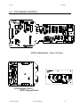
5.2
Section 5
PCB ASSEMBLY DRAWINGS
(PCB-A) Main Board – (Non CE Units)
(PCB-B)Display Board
(PCB-C)Keypad Board
YSI, Incorporated
85 Service Manual
28
Service
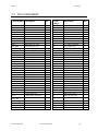
5.3
Section 5
PCB COMPONENTS
Circuit Symbol
Description
Qty
Circuit
Symbol
Description
Qty
YSI-85-A
JP1
JP2
JP3,JP7,JP8
JP4
JP5
JP6
R1,R21,R22
R2,R31
R3(25PPM)
R4,R5(25PPM)
R6
R7
R8
R9
R10
R11,R12,R32
R13,R14
R15,R16,R20,R24
R17,R19,R25
R18
R23
R26(15PPM)
R27,R29,R34,R35
R28
R30
R33
RN1
C1
C2,C8,C9
C3
C4,C5
C6,C7,C10~~ C14,C2
1,C23~~ C27
C15,C19,C20
C16,C18
C17
C22
BOARD. MAIN BARE
CONN. 6 PIN. RT. ANGLE
CONN. 8 PIN. WAFER
CONN. 3 PIN. WAFER
CONN. 2 PIN. MALE. POL
CONN. 12 PIN. WAFER
CONN. 5 PIN. RT. ANGLE
RES. 10K, 1%, 1/4W
RES. 40.2K, 1%, 1/4W
RES. 887K, 1%, 1/4W
RES. 49.9K, 1%, 1/4W
RES. 45.3K, 1%, 1/4W
RES. 4.53K, 1%, 1/4W
RES. 374, 1%, 1/4W
RES. 124, 1%, 1/4W
RES. 100,5%, 1/4W
RES. 10M, 5%, 1/4W
RES. 220, 5%, 1/4W
RES. 1K, 5%, 1/4W
RES. 100K, 1%, 1/4W
RES. 54.9K, 1%, 1/4W
RES. 15.8K, 1%, 1/4W
RES. 6.81K, 0.1%, 1/4W
RES. 100K, 1%, 1/4W
RES. 909K, 1%, 1/4W
RES. 365K, 1%, 1/4W
RES. 15K, 1%, 1/4W
RES. SIP. 100K
CAPR. TANT. 3.3uF,25V
CAPR. CER. 470pF
CAPR. CER. 47pF
CAPR. TANT. 10uF, 16V
CAPR. MPE. 0.1uF,63V
1
1
1
3
1
1
1
3
2
1
2
1
1
1
1
1
3
2
4
3
1
1
1
4
1
1
1
1
1
3
1
2
13
C28, C29
D1~~ D14
U1
U2, U4
U3
U5
U6
U7
U8
U9
U10
U11
U12 (if need)
Q1
X1
JP1
LCD1
U1
U2
U3
D1,D2
D3~~ D8
C1
C2,C3,C4
R1
R2
R3
R4
R5
R6
R7
R8
Q1
CAPR. CER. 20pF
DIODE. 1N4148
I.C. MOTOR. MC34182P
I.C., M74HC4052B
I.C. NATL. LMC6484IN
I.C. PMI OP290GP
I.C. ,TC55RP5002EZB
I.C. . MC14052BCP
I.C. TLDN. TC500CPE
I.C. HARR. L8069
I.C. MC68HC711E9CFN2
I.C. ATMEL. AT24C16PC
I.C. SEIKO. 8054ALR
FET. 2N7000
CRYSTAL 4.00 MHz
CONN. 12 PIN
LCD DISPLAY
I.C. HARRS 7663SCPA
I.C. TLDN TC7662ACPA
I.C. HD61603
DIODE IN4148
LED LAMP, HLMP-1540
CAPR. ELE. 2.2uF, 16V
CAPR. ELE. 10uF, 16V
RES. 750K, 1%, 1/4W
RES. 261K, 1%, 1/4W
RES. 357K, 1%, 1/4W
RES. 15K, 5%, 1/4W
RES, 100K, 5%, 1/4W
RES. 82, 5%, 1/4W
RES. 15, 5%, 1/4W
RES. 100, 5%, 1/4W
TRSTR. MPSA06, PNP
2
14
1
2
1
1
1
1
1
1
1
1
1
1
1
1
1
1
1
1
2
6
1
3
1
1
1
1
1
1
1
1
1
CAPR. MPE. 1uF,63V
CAPR. CER. 100pF
CAPR. MPE. 0.33uF, 63V
CAPR. ELE. 2.2uF, 16V
3
2
1
1
---------------
MINI JUMPER. DS-001
IC SOCKET. 52P OLCC
2
1
YSI, Incorporated
85 Service Manual
29
Service
5.4
Section 5
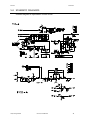
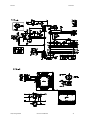
SCHEMATIC DIAGRAMS
Schematic diagrams are representative of actual circuits.
YSI, Incorporated
85 Service Manual
30
Service
YSI, Incorporated
Section 5
85 Service Manual
31
Service
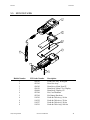
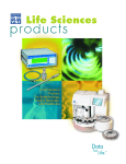
5.5
Section 5
EXPLODED VIEW
1
3
4
2
6
5
4
Bubble Number
1
2
3
3
3
4
5
6
6
6
6
YSI, Incorporated
YSI Order Number
038501
055242
038502
030156
030898
055204
055244
118510
118522
118527
118519
Description
Front Case Assy, W/Keypad
Rear Case Assy
Board Assy, Main, Non CE
Board Assy, Main, CE w/ Display
Board Assy, Display, CE
Kit, Case Hardware
Kit, Battery Hardware
Probe & Cable Assy, 10 feet
Probe & Cable Assy, 25 feet
Probe & Cable Assy, 50 feet
Probe & Cable Assy, 100 feet
85 Service Manual
32
SECTION 6
WARRANTY AND REPAIR
YSI Model 85 Handheld Meters are warranted for two years from date of purchase by the end user
against defects in materials and workmanship. YSI Model 85 probes and cables are warranted for one
year from date of purchase by the end user against defects in material and workmanship. Within the
warranty period, YSI will repair or replace, at its sole discretion, free of charge, any product that YSI
determines to be covered by this warranty.
To exercise this warranty, write or call your local YSI representative, or contact YSI Customer Service
in Yellow Springs, Ohio. Send the product and proof of purchase, transportation prepaid, to the
Authorized Service Center selected by YSI. Repair or replacement will be made and the product
returned transportation prepaid. Repaired or replaced products are warranted for the balance of the
original warranty period or at least 90 days from date of repair or replacement.
Limitation of Warranty
This Warranty does not apply to any YSI product damage or failure caused by (i) failure to install, operate or use
the product in accordance with YSI’s written instructions, (ii) abuse or misuse of the product, (iii) failure to
maintain the product in accordance with YSI’s written instructions or standard industry procedure, (iv) any
improper repairs to the product, (v) use by you of defective or improper components or parts in servicing or
repairing the product, or (vi) modification of the product in any way not expressly authorized by YSI.
THIS WARRANTY IS IN LIEU OF ALL OTHER WARRANTIES, EXPRESSED OR IMPLIED,
INCLUDING ANY WARRANTY OF MERCHANTABILITY OR FITNESS FOR A
PARTICULAR PURPOSE. YSI’s LIABILITY UNDER THIS WARRANTY IS LIMITED TO
REPAIR OR REPLACEMENT OF THE PRODUCT, AND THIS SHALL BE YOUR SOLE AND
EXCLUSIVE REMEDY FOR ANY DEFECTIVE PRODUCT COVERED BY THIS
WARRANTY. IN NO EVENT SHALL YSI BE LIABLE FOR ANY SPECIAL, INDIRECT;
INCIDENTAL OR CONSEQUENTIAL DAMAGES RESULTING FROM ANY DEFECTIVE
PRODUCT COVERED BY THIS WARRANTY.
Warranty and Repair
Section 7
AUTHORIZED U.S. SERVICE CENTERS
NORTH REGION / EAST REGION
YSI Incorporated • Repair Center • 1725 Brannum Lane • Yellow Springs, Ohio • 45387 • Phone:
(937) 767-7241• (800) 897-4151• Fax: (937) 767-9353 • E-Mail: [email protected]
SOUTH REGION
C.C. Lynch & Associates • 212 E. 2nd Street • Suite 203 • Pass Christian, Mississippi • 39571 •
Phone: (800) 333-2252 • (228) 452-4612 • Fax: (228) 452-2563
WEST REGION
EnviroServices & Repair • 1110 Burnett Avenue, Suite D • Concord, CA • 94520 • Phone:
(800)550-5875 • Fax: (510)674-8655
YSI, Incorporated
85 Service Manual
34
Warranty and Repair
Section 7
INTERNATIONAL SERVICE CENTERS
YSI Incorporated
[email protected]
• Repair Center • 1725 Brannum Lane • Yellow Springs, Ohio • 45387 • Phone:
(937) 767-7241• E-Mail:
Lynchford House • Lynchford Lane • Farnborough • Hampshire • GU146LT • Phone: (44-1252)
514711 • Fax: (44-1252) 511855 • Tlx: 858210
Sakura – Building 6-5-6-13 • Shinjuku, Shinjuku-ku, Tokyo • 160 • Phone: (81-3) 5360-3561 • Fax:
(81-3) 5360-3565
SPECIALTY SERVICE CENTERS
Aquaculture
Aquatic Eco Systems, Inc. • 1767 Benbow Court • Apopka, Florida • Phone: (407) 886-3939 • Fax:
(407) 886-6787
Aquacenter • 166 Seven Oaks Road • Leland, Mississippi • 38756 • Phone: (601) 378-2861 • Fax:
(601) 378-2862
Wastewater
Q.C. Services • P.O. Box 68 • Harrison, Maine • 04040 • Phone: (207) 583-2980
Q.C. Services • P.O. Box 14831 • Portland, Oregon • 97293 • Phone: (503) 236-2712
YSI, Incorporated
85 Service Manual
35
Warranty and Repair
YSI, Incorporated
Section 7
85 Service Manual
36
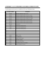
APPENDIX A ACCESSORIES AND REPLACEMENT PARTS
The following parts and accessories are available from YSI or any YSI Franchise Dealer.
YSI Order Number
Description
YSI 5906
Replacement Membrane Cap Kit ( 6 each )
YSI 3161
Conductivity Calibration Solution 1,000 µ/cm (1 Quart)
YSI 3163
Conductivity Calibration Solution 10,000 µ/cm (1 Quart)
YSI 3165
Conductivity Calibration Solution 100,000 µ/cm (1 Quart)
YSI 3167
Conductivity Calibration Solution 1,000 µ/cm (8 pints)
YSI 3168
Conductivity Calibration Solution 10,000 µ/cm (8 pints)
YSI 3169
Conductivity Calibration Solution 50,000 µ/cm (8 pints)
YSI 5520
Carrying Case
118510
Probe & Cable Assembly (10 feet)
118522
Probe & Cable Assembly (25 feet)
118527
Probe & Cable Assembly (50 feet)
118519
Probe and Cable Assembly (100 feet)
038501
Front Case Cover
055242
Rear Case Cover
055244
Battery Cover Kit
055204
Case Hardware Kit
055219
Sponge, Storage Chamber
038502
Main Board Assembly
038213
Brush, Electrode Cleaning
030156
Main Board Assembly, CE, w/o Display
030898
Display Assembly, CE versions
Accessories and Replacement Parts
YSI, Incorporated
Appendix A
85 Service Manual
38
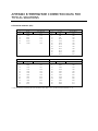
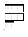
APPENDIX B TEMPERATURE CORRECTION DATA FOR
TYPICAL SOLUTIONS
A. Potassium Chloride (KCl)
Concentration: 1 x 10⁻¹ mole/liter
Concentration: 1 mole/liter
°C
m_/cm
%/°C (to 25°C)
°C
m_/cm
%/°C (to 25°C)
0
65.10
1.67
0
7.13
1.78
5
73.89
1.70
5
8.22
1.80
10
82.97
1.72
10
9.34
1.83
15
92.33
1.75
15
10.48
1.85
20
101.97
1.77
20
11.65
1.88
25
111.90
1.80
25
12.86
1.90
30
14.10
1.93
35
15.38
1.96
37.5
16.04
1.98
40
16.70
1.99
45
18.05
2.02
50
19.43
2.04
Concentration: 1 x 10⁻² mole/liter
Concentration: 1 x 10⁻³ mole/liter
°C
m_/cm
%/°C (to 25°C)
°C
m_/cm
%/°C (to 25°C)
0
0.773
1.81
0
0.080
1.84
5
0.892
1.84
5
0.092
1.88
10
1.015
1.87
10
0.105
1.92
15
1.143
1.90
15
0.119
1.96
20
1.275
1.93
20
0.133
1.99
25
1.412
1.96
25
0.147
2.02
30
1.553
1.99
30
0.162
2.05
35
1.697
2.02
35
0.178
2.07
37.5
1.771
2.03
37.5
0.186
2.08
40
1.845
2.05
40
0.194
2.09
45
1.997
2.07
45
0.210
2.11
50
2.151
2.09
50
0.226
2.13
** Charts developed by interpolating data from International Critical Tables , Vol. 6, pp. 229-253, McGraw-Hill Book Co., NY.
Temperature Correction Data
Appendix B
B. Sodium Chloride * (NaCl)
Saturated solutions at all temperatures
Concentration: 0.5 mole/liter
°C
m_/cm
%/°C (to 25°C)
°C
m_/cm
%/°C (to 25°C)
0
134.50
1.86
0
25.90
1.78
5
155.55
1.91
5
29.64
1.82
10
177.90
1.95
10
33.61
1.86
15
201.40
1.99
15
37.79
1.90
20
225.92
2.02
20
42.14
1.93
25
251.30
2.05
25
46.65
1.96
30
277.40
2.08
30
51.28
1.99
35
56.01
2.01
37.5
58.40
2.02
40
60.81
2.02
45
65.65
2.04
50
70.50
2.05
Concentration: 1 x 10⁻¹ mole/liter
Concentration: 1 x 10⁻² mole/liter
°C
m_/cm
%/°C (to 25°C)
°C
m_/cm
%/°C (to 25°C)
0
5.77
1.83
0
0.632
1.87
5
6.65
1.88
5
0.731
1.92
10
7.58
1.92
10
0.836
1.97
15
8.57
1.96
15
0.948
2.01
20
9.60
1.99
20
1.064
2.05
25
10.66
2.02
25
1.186
2.09
30
11.75
2.04
30
1.312
2.12
35
12.86
2.06
35
1.442
2.16
37.5
13.42
2.07
37.5
1.508
2.17
40
13.99
2.08
40
1.575
2.19
45
15.14
2.10
45
1.711
2.21
50
16.30
2.12
50
1.850
2.24
Concentration: 1 x 10⁻³ mole/liter
°C
m_/cm
%/°C (to 25°C)
0
0.066
1.88
5
0.076
1.93
10
0.087
1.98
15
0.099
2.02
20
0.111
2.07
25
0.124
2.11
30
0.137
2.15
35
0.151
2.19
37.5
0.158
2.20
40
0.165
2.22
45
0.180
2.25
50
0.195
2.29
* Charts developed by interpolating data from the CRC Handbook of Chemistry and Physics, 42nd ed., p. 2606, The Chemical Rubber Company,
Cleveland.
YSI, Incorporated
85 Service Manual
40
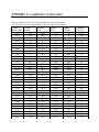
APPENDIX C CALIBRATION VALUES TABLE
Table A: Calibration values for various atmospheric pressures and altitudes.
Note: This table is for your information only. It is not required for calibration.
Pressure
Inches of Hg
30.23
29.92
29.61
29.33
29.02
28.74
28.43
28.11
27.83
27.52
27.24
26.93
26.61
26.34
26.02
25.75
25.43
25.12
24.84
24.53
24.25
23.94
23.62
23.35
23.03
22.76
22.44
22.13
21.85
21.54
21.26
20.94
20.63
Pressure
mm Hg
768
760
752
745
737
730
722
714
707
699
692
684
676
669
661
654
646
638
631
623
616
608
600
593
585
578
570
562
555
547
540
532
524
Pressure
kPA
102.3
101.3
100.3
99.3
98.3
97.3
96.3
95.2
94.2
93.2
92.2
91.2
90.2
89.2
88.2
87.1
86.1
85.1
84.1
83.1
82.1
81.1
80.0
79.0
78.0
77.0
76.0
75.0
74.0
73.0
71.9
70.9
69.9
Altitude
in feet
-276
0
278
558
841
1126
1413
1703
1995
2290
2587
2887
3190
3496
3804
4115
4430
4747
5067
5391
5717
6047
6381
6717
7058
7401
7749
8100
8455
8815
9178
9545
9917
Altitude
in meters
-84
0
85
170
256
343
431
519
608
698
789
880
972
1066
1160
1254
1350
1447
1544
1643
1743
1843
1945
2047
2151
2256
2362
2469
2577
2687
2797
2909
3023
Calibration
Value in %
101
100
99
98
97
96
95
94
93
92
91
90
89
88
87
86
85
84
83
82
81
80
79
78
77
76
75
74
73
72
71
70
69
Calibration Values Table
20.35
YSI, Incorporated
Appendix B
517
68.9
85 Service Manual
10293
3137
68
42
Calibration Values Table
YSI, Incorporated
Appendix B
85 Service Manual
43
Calibration Values Table
YSI, Incorporated
Appendix B
85 Service Manual
44
1725 Brannum Lane
Yellow Springs, Ohio 45387
(800) 897-4151 (937) 767-7241
FAX (937) 767-9353
E-mail: [email protected]
Website: http://www.YSI.com
Item #038504
DRW# A38504B
May 1998