1
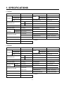
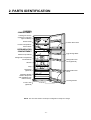
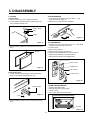
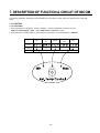
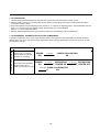
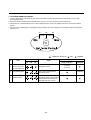
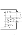
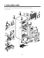
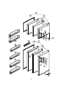
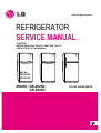
http://biz.lgservice.com
REFRIGERATOR
SERVICE MANUAL
CAUTION
BEFORE SERVICING THE UNIT, READ THE "SAFETY
PRECAUTIONS" IN THIS MANUAL.
Ref. No.
GR-262SQ
GR-292SQ
MODEL: GR-262SQ
GR-292SQ
COLOR: SUPER WHITE
CONTENTS
SAFETY PRECAUTIONS ....................................................................................................................................................... 2
SERVICING PRECAUTIONS.................................................................................................................................................. 3
SPECIFICATIONS................................................................................................................................................................... 4
PARTS IDENTIFICATION ....................................................................................................................................................... 5
DISASSEMBLY.................................................................................................................................................................... 6-7
DOOR................................................................................................................................................................................... 6
DOOR SWITCH.................................................................................................................................................................... 6
FAN AND FAN MOTOR........................................................................................................................................................ 6
DEF' CONTROL ASM .......................................................................................................................................................... 7
REFRIGERATOR ROOM LAMP .......................................................................................................................................... 7
CONTROL BOX-R................................................................................................................................................................ 7
REPLACEMENT OF DOOR OPENING TYPE...................................................................................................................8-9
ADJUSTMENT................................................................................................................................................................. 10-11
COMPRESSOR.................................................................................................................................................................. 10
PTC-STARTER................................................................................................................................................................... 10
OLP (OVER LOAD PROTECTOR)..................................................................................................................................... 11
CIRCUIT DIAGRAM.............................................................................................................................................................. 11
TROUBLESHOOTING..................................................................................................................................................... 12-17
COMPRESSOR AND ELECTRIC COMPONENTS ........................................................................................................... 12
PTC AND OLP.................................................................................................................................................................... 13
ANOTHER ELECTRIC COMPONENT............................................................................................................................... 14
SERVICE DIAGNOSIS CHART.......................................................................................................................................... 15
REFRIGERATING CYCLE ............................................................................................................................................ 16-17
DESCRIPTION OF FUNCTION & CIRCUIT OF MICOM .................................................................................................18-34
EXPLODED VIEW ........................................................................................................................................................... 35-37
REPLACEMENT PARTS LIST ............................................................................................................................................ 38-
SAFETY PRECAUTIONS
Please read the followings before servicing your refrigerator.
7. When you stand up during observing the lower part
with the upper door open, move with care to prevent
head wound which may happen by hitting the upper
door.
1. Check if an electric leakage occurs in the set.
2. To prevent electric shock, unplug prior to servicing.
3. In case of testing with power on, wear rubber gloves to
prevent electric shock.
8. When sloping the set, remove any materials on the set,
especially thin plate type. (ex.: glass shelf or books.)
4. If you use any appliances, check regular current, voltage
and capacity.
9. When servicing evaporator part, wear cotton gloves
without fail. It is to prevent wound by sharp fin of
evaporator.
5. Don't touch metal products in cold freezer with wet hand.
It may cause frostbite.
6. Prevent water flowing to electric elements in mechanical
parts.
10. Leave a breakage of refrigerating cycle to a heavy
service center. The gas in cycle inside may soil
ambient air.
-2-
SERVICING PRECAUTIONS
Air Recharging in Compressor
vacuum operation is over, add the quantity in grams of R134a to the refrigerant system. Remember that every
system has an exact quantity of R-134a with a tolerance of
±5 grams that can be added. (Figure 4)
Test the refrigeration by connecting it electrically before
refilling operation. It is necessary to ascertain the function
of the motor-compressor and identify the defects
immediately. If the defects have been found, empty the old
system of eventual R-134a residue by breaking off the end
of the extension piece at its narrow point. (Figure 1)
Replace the filter and any damaged components. Unsolder
and pull off the piece remaining inside the service tube and
then attach an extension completely with male Hansen and
last, solder it to the same tube again. (Figure 2)
CHARGE TUBE
EXTENSION
POINT TO BE BROKEN
TO THE R-134a CYLINDER
FEMALE
HANSEN
TO THE REFRIGERATION
SYSTEM
MALE HANSEN
Figure 4
SERVICE TUBE EXTENSION
SOLDERING POINT
Figure 1
Before performing this operation (if the vacuum pump and
refilling cylinder are connected), make sure that the valve
placed between the vacuum pump and refilling tube are
closed to keep the Freon for adding to the system. (Figure 5)
Figure 2
It is necessary to execute the soldering operation with
valve open so that the fumes caused by oil residue can
come out freely without blowholes between two tubes
during heating the point to be soldered.
The extension fitted with the male Hansen is connected to
the female fitting of the vacuum pump tube. (Figure 3)
FILLING OR
CHARGE TUBE
VALVE TO BE OPENED
WHEN REFILLING
TO THE REFRIGERATION
SYSTEM
TO THE CHARGE
CYLINDER
VALVE TO BE CLOSED
AFTER VACUUM
TO THE
VACUUM
PUMP
TO THE
VACUUM
PUMP
PRESSURE
GAUGE
Figure 5
In addition, check the graduated scale on the cylinder for
the quantity of R-134a to be added, for example, if we have
750 grams of Freon in the cylinder and must add 165
grams to the group, this amount will be reached when R134a has dropped to 585 grams, remembering that the
indicator shows a lower limit of meniscus. Do this after
choosing the scale corresponding to the gas pressure
different scales reported as the same gas pressure
indicated by the pressure gauge on the top of the column.
To make R-134a flow into the system, open the valve
placed at the base of the cylinder and connected to the
filling tube. The amount of Freon cannot be added to the
system all at once because it may cause a blocking of
motor-compressor. Therefore, proceed by adding original
quantity of about 20-30 grams and close the valve
immediately.
The pressure rises and the motor-compressor must start,
sucking the gas and making the pressure go down again.
Regulate the valve again, maintaining the same manner
until reaching to the quantity of R-134a established for the
system being charged. When the system is running, the
suction pressure must be stabilized between 0.30 to 0.6
atmosphere.
Figure 3
Air evacuating from the system begins so soon as the
pump starts. The refrigeration system must be kept under
vacuum until the reading on the low-pressure gauge
indicates vacuum (0 absolute, -1 atm., -760 mm hg) in any
case it is advisable to keep the pump running for about 30
minutes. (Figure 3)
In case that a considerable leakage occurs and to stop the
vacuum pump will be necessary and add a small quantity
of Freon to the system, if vacuum should not be obtained
(pressure gauge can't fall to 1 atmosphere), start the
refrigeration unit and find the leakage with the special leakfinder. When the defective soldering point is visible, re-do it
after opening the extension tube valve and reestablishing
the normal outside pressure inside the group.
Because the melted alloy is sucked into the tubes and
block them, the pressure must be rebalanced when
vacuum is in the system in soldering. As soon as the
-3-
1. SPECIFICATIONS
1-1 GR-262
ITEMS
SPECIFICATIONS
FREEZER
ITEMS
61
SPECIFICATIONS
FREEZER
1 EA
REFRIGERATOR
2 EA
SHELF
NET CAPACITY REFRIGERATOR
(l)
TOTAL
158
219
VEGETABLE TRAY
Drawer Type
GR-262S(V)Q 540(W)X610(D)X1510(H)
EGG TRAY
1 Piece
GR-262Q(V)C 540(W)X628(D)X1510(H)
ICE TRAY
1 Piece (*2)
NET WEIGHT (kg)
46
ICE BANK
1 Piece
COOLING SYSTEM
Fan Cooling
COMPRESSOR
P.T.C Starting Type
TEMPERATURE
FREEZER
Knob Shutter
EVAPORATOR
Fin Tube Type
CONTROL
REFRIERATOR
Micom Control
CONDENSER
Pipe On Sheet Type
Full Automatic
REFRIGERANT
R134a (120g)
Heater Defrost
LUBRICATING OIL
FREOL α 22G (210cc)
OUT CASE
Coated Steel Sheet
DEFROSTING DEVICE
L-CORD, PLATE HEATER
INNER CASE
ABS
INSULATION
Polyurethane Foam
DIMENSIONS (mm)
DEFROSTING SYSTEM
(*) : OPTION
1-2 GR-292
ITEMS
SPECIFICATIONS
FREEZER
ITEMS
61
SPECIFICATIONS
FREEZER
1 EA
REFRIGERATOR
2 EA
SHELF
NET CAPACITY REFRIGERATOR
(l)
TOTAL
176
237
VEGETABLE TRAY
Drawer Type
GR-292S(V)Q 540(W)X610(D)X1600(H)
EGG TRAY
1 Piece
GR-292Q(V)Q 540(W)X628(D)X1600(H)
ICE TRAY
1 Piece (*2)
NET WEIGHT (kg)
49
ICE BANK
1 Piece
COOLING SYSTEM
Fan Cooling
COMPRESSOR
P.T.C Starting Type
TEMPERATURE
FREEZER
Knob Shutter
EVAPORATOR
Fin Tube Type
CONTROL
REFRIERATOR
Micom Control
CONDENSER
Pipe On Sheet Type
Full Automatic
REFRIGERANT
R134a (120g)
Heater Defrost
LUBRICATING OIL
FREOL α 22G (210cc)
OUT CASE
Coated Steel Sheet
DEFROSTING DEVICE
L-CORD, PLATE HEATER
INNER CASE
ABS
INSULATION
Polyurethane Foam
DIMENSIONS (mm)
DEFROSTING SYSTEM
(*) : OPTION
-4-
2. PARTS IDENTIFICATION
FREEZER
COMPARTMENT
Twisting Ice Service
(Optional) or General
Type Ice Making
Freezer Shelf
Freezer Door Rack
Freezer Temperature
Control Knob
REFRIGERATOR
COMPARTMENT
Egg Storage Rack
Chilled Compartment
Refrigerator Temperature
Control Micom
Refrigerator Door
Rack (Optional)
Shelves
Lamp
Deodorizer
(Optional)
Refrigerator Door
Rack
Vegetable Drawer
Used to keep fruits
and vegetables, etc.
fresh and crisp.
Leveling Screws
Cover Lower
(Optional)
NOTE : This is a basic model. The shape of refrigerator is subject to change.
-5-
3. DISASSEMBLY
3-1 DOOR
3-2 DOOR SWITCH
● Freezer
1. To remove the door switch, pull out it with a '—' type
driver as shown in (figure 9).
2. Disconnect the lead wire from the switch.
Door
1. Remove the hinge cover by pulling it upwards.
2. Loosen hexagonal bolts fixing the upper hinge to the
body and lift the freezer door.
HINGE COVER
BOLT
HINGE
Figure 9
3-3 THERMISTOR
Figure 6
1. Remove the Cover Lamp-R by the use of '–––' type driver
inserting in the low holes of the cover.
2. Loose 2 screw.
3. Pull the Control Box-R.
4. Disconnect the Housing of lead wire.
5. Separate the INSU'Multi Duct and Control Box-R.
6. Separate the Thermistor and Control Box-R.
7. Separate the Thermistor and Display PCB.
3. Pull out the door gasket to remove from the door foam
Ass'y.
GASKET
INSU'MULTI DUCT
DISPLAY PCB
THERMISTOR
Figure 7
CONT' BOX-R
Refrigerator Door
1. Loosen hexagonal bolts fixing the lower hinge to the
body to remove the refrigerator door only.
●
COVER LAMP-R
Figure 10
3.4 FAN AND FAN MOTOR
LOWER HINGE
BOLT
1. Remove the freezer shelf.
2. Separate the twist by pulling right.
3. Loose 1 screw.
4. Pull out the Grille Fan and Shroud-F.
Figure 8
2. Pull out the door gasket to remove from the door foam
Ass'y.
SCREW
Figure 11
-6-
3-6 REFRIGERATOR ROOM LAMP
5. Disconnect the housing of lead wire.
6. Separate the Fan Assy.
7. Loose 2 screw fixed to the Bracket.
8. Pull out Shroud-F remove the Fan Motor Assy.
9. Separate the Motor Bracket and Rubber.
1. Remove the cover lamp-R by pulling with a '–––' type
driver.
2. Remove the lamp-R by turning.
REFRIGERATOR ROOM LAMP
FAN MOTOR
SHROUD-F
BRACKET
FAN
Figure 17
GRILLE FAN
Figure 12
3-7 CONTROL BOX-R
3-5 DEF' CONTROL ASM
1. Remove the Cover Lamp-R.
Def control ASM consists of Defrost Sensor and FUSE–M.
Defrost Sensor functions to defrost automatically and it is
attached to the Evaporator and the metal side of the case
senses Temp.
Fuse-M is a kind of safety device for preventing overheating of the Heater when defrosting.
At the temperature of 72°C, it stops the emission of TEMP
from the Defrost Heater.
1. Pull out the shroud-F after removing the Grille Fan.
(Figure 13)
2. Separate the connectors connected with the Def Control
ASM and replace the Def Control ASM after cutting the
Tie Wrap. (Figure 14)
CONTROL BOX-R
COVER LAMP
Figure 18
SHROUD-F
DEF CONTROL ASM
2. Loosen 2 screws.
3. Full the Control Box-R.
4. Separate the lead wire Housing.
Figure 13
Figure 14
-7-
- Converting Door is Optional
3-8 REPLACEMENT OF DOOR OPENING TYPE
Precaution
1. Before replacing the door opening type, first of all, you should take out
foodstuffs and accessories like shelves or trays, and so on which are not fixed
in the refrigerator.
●
2. Use the '+' Driver, Bolt Driver, Torque Wrench or Spanner to fix or remove the
bolt.
3. Be careful not to fall down the refrigerator in disassembling or assembling the
Hinge Lower and the Adjustable Screw Asm. Don't lay the refrigerator down in
working with it, it will cause to get out of order.
4. Be careful not to drop the door in disassembling or assembling the freezer or
the refrigerator door.
5. This refrigerator, according to the install position or user's liking, can be used
as the type of opening from the right or the left.
HOW TO REPLACE THE DOOR OPENING TYPE
1
Separate the Cap ➊ and Hinge Upper ➋.
2
Separating the Freezer Door ➌.
3
2
1
3
Separating the Hinge-C ➍ and the Refrigerator
4
Door ➎.
4
5
Separating the Hinge Lower ➏.
6
-8-
6 Assemble the Hinge Lower ➏.
the Position of Adjustable Screw
Assembly ➐.
5 Move
7
6
the Cap ➑, Bracket ➒ of the Refrigerator
Door.
7 Move
Move the Cap ➓ and Assemble the Hinge-C ➍.
removing the washer.
8 After
8
10
4
9
Assembe the Door Stopper-F é for Right
Type.
9 Opening
the Cap è and Assemble the Freezer
Door ➌.
10 Move
3
3
12
5
11
12 Assemble the Hinge Upper ➋ and the Cap ➊.
11 Move the Pin Position ê of the Hinge Upper.
13
2
1
-9-
4. ADJUSTMENT
4-1 COMPRESSOR
4-1-1 Role
4-2-3 PTC-Applied Circuit Diagram
to Starting Method of Motor
● According
The compressor inhales low temperature and low pressure
gas evaporated from Evaporator of the Refrigerator, and
condenses this gas to high temperature and high pressure
gas, and then plays delivering role to Condenser.
OVERLOAD PROTECTOR
C
4-1-2 Composition
The Compressor is Composed of Compressor Apparatus
compressing gas, Compressor Motor moving Compressor
Apparatus and Case protecting Compressor Apparatus
and Motor. There are PTC-Starter, and Over Load
Protector (OLP) in the Compressor outside. On the other
hand, because the Compressor consists of 1/1000mm processing
precision components and is sealed after producing without dust
or humidity, deal and repair with care.
4-1-3 Note to Use
(1) Be careful not to allow over-voltage and over-current.
(2) No Strike
If applying forcible power or strike (dropping or careless
dealing), poor operation and noise may occur.
(3) Use proper electric components appropriate to the
Compressor.
(4) Note to Keep Compressor.
If Compressor gets wet in the rain and rust in the pin of
Hermetic Terminal, poor operation and poor contact
may cause.
(5) Be careful that dust, humidity, and flux due to welding
don't inflow in Compressor inside in replacing
Compressor. Dust, humidity, and flux due to welding
which inflows to Cylinder may cause lock and noise.
4-2 PTC-STARTER
4-2-1 Composition of PTC-Starter
(1) PTC (Positive Temperature Coefficient) is no-contact
semiconductor starting device which uses ceramic
material and the material consists of BaTiO3.
(2) The higher the temperature is, the higher resistance
value becomes . These features are used as starting
device of Motor.
4-2-2 Role of PTC-Starter
(1) PTC is attached to Hermetic Compressor used for
Refrigerator, Show Case and starts Motor.
(2) Compressor for household refrigerator applies singlephase induction Motor.
For normal operation of single-phase induction motor, in
the starting operation flows in both main coil and subcoil. After the starting is over, the current is cut off in
subcoil. The proper features of PTC play the above all
roles. So, PTC is used as a starting device of motor.
PTC
5
S
3
6
PTC STARTER
COMPRESSOR
MOTOR
M
M
S
HERMETIC
TERMINAL
RSIR
4-2-4 Motor Restarting and PTC Cooling
(1) For restarting after power off during normal
Compressor Motor operation, plug the power cord after
5 min. for pressure balance of Refrigerating Cycle and
PTC cooling.
(2) During normal operation of Compressor Motor, PTC
elements generate heat continuously. Therefore,
if PTC isn't cooled for a while after power off, Motor
can't operate again.
4-2-5 Relation of PTC-Starter and OLP
(1) If power off during operation of Compressor and power
on before PTC is cooled, (instant shut-off within 2 min.
or reconnect a power plug due to misconnecting),
PTC isn't cooled and a resistance value grows. As a
result, current can't flow to the sub-coil and Motor can't
operate and OLP operates by flowing over current in
only main-coil.
(2) While the OLP repeats on and off operation about 3-5
times, PTC is cooled and Compressor Motor performs
normal operation.
If OLP doesn't operate when PTC is not cooled,
Compressor Motor is worn away and causes circuitshort and fire. Therefore, use a proper fixed OLP
without fail.
4-2-6 Note to Use PTC-Starter
(1) Be careful not to allow over-voltage and over-current.
(2) No Strike
Don't apply a forcible power or strike.
(3) Keep apart from any liquid.
If liquid such as oil or water inflows into PTC,
PTC materials it may break due to insulation breakdown
of material itself.
(4) Don't change PTC at your convenience.
Don't disassemble PTC and mold. If damaging to
outside of PTC-starter, resistance value alters and poor
starting of compressor motor may cause.
(5) Use a properly fixed PTC.
- 10 -
4-3 OLP (OVER LOAD PROTECTOR)
CONTACTING
POINT
4-3-1 Definition of OLP
(1) OLP (OVER LOAD PROTECTOR) is attached to
Hermetic Compressor and protects Motor by cutting off
current in Compressor Motor by Bimetal in the OLP in
case of over-rising temperature.
(2) When over-voltage flows to Compressor motor, Bimetal
works by heating the heater inside OLP,
and OLP protects Motor by cutting off current which
flows to Compressor Motor.
COVER
BIMETAL
CONTACTING
POINT
HEATER
TERMINALS
4-3-2 Role of OLP
(1) OLP is attached to Hermetic Compressor used to
Refrigerator and Show Case and prevents Motor Coil
from being started in the Compressor.
(2) Do not turn the Adjust Screw of OLP in any way for
normal operation of OLP.
(Composition and connection Diagram of OLP
BIMETAL
ADJUST
SCREW
HEATER
5. CIRCUIT DIAGRAM
NOTE : 1. This is a basic diagram and specifications vary in different localities.
- 11 -
Figure 21
6. TROUBLESHOOTING
6-1 COMPRESSOR AND ELECTRIC COMPONENTS
1
Power
Source.
Remove the PTCStarter from the
Compressor and
measure the voltage
between Terminal C of
Compressor and
Terminals 5 or 6 of PTC.
(Rating Voltage
±10%)?
No Voltage.
OLP disconnected?
YES
2
YES
Replace OLP.
5
Check connection
condition.
Advise the customer
to use a regular
Trans.
Applied voltage isn't
in the range of Rating
Voltage ±10%.
2
3
Check the
resistance of
Motor
Compressor.
Check the resistance
among M-C, S-C and
M-S in Motor
Compressor.
Check the
resistance of
PTC-Starter.
Check the resistance of
two terminals in PTCStarter.
Check OLP.
Check if applying
a regular OLP.
Reconnect.
5
YES
NO
3
Replace Compressor.
3
YES
4
5
4
Replace
PTC-Starter.
NO
5
YES
4
5
Check
starting state.
Measure minimum
starting voltage after 5
min. for balancing cycle
pressure and cooling the
PTC.
OLP works within
30 sec. in forcible
OLP operation by
turning instant power
on and off.
Components start in
the voltage of Rating
Voltage ±10% below.
YES
NO
Replace OLP.
YES
O.K.
NO
- 12 -
5
1
6-2 PTC AND OLP
Normal operation of
Compressor is
impossible or poor.
Observation value is
220V/50Hz : 22Ω±30%
115V/60Hz : 6.8Ω±30%
240V/50Hz : 33Ω±30%
127, 220V/60Hz : 22Ω
±30%
Separate the PTC-Starter
from Compressor and
measure the resistance
between No. 5 and 6 (only
RSIR type) or No. 4 and 5 of
PTC-Starter with a Tester or
Whistone Bridge.
(Figure 37)
The resistance value is 0
or serveral hundreds Ω.
The value is ∞.
Separate the OLP from the
Compressor and check the
resistance value between
two terminals of OLP with
a Tester. (Figure 38)
YES
Check another
electric components.
NO
Replace OLP.
4
5
6
3
Figure 37
Figure 38
- 13 -
Check another
electric
components.
Replace
PTC-Starter.
6-3 ANOTHER ELECTRIC COMPONENTS
▼ Cooling is impossible
Compressor
doesn't run.
Running state of
Compressor is poor.
Check if current flows to
the following
components.
Cause.
a. Thermistor
Poor contacting.
b. Starting devices
Shorted or broken.
c. OLP
Poor contacting
or shorted.
d. Compressor coil
Coil shorted.
e. Circuit Parts
Poor contacting
or shorted.
Replace
each component.
Check a starting
voltage.
Low voltage.
Raise the voltage.
Check if current flows
to starting devices.
Poor contacting
and broken.
Replace
each component.
Check current flowing
in sub-coil of
Compressor.
Shorted.
Check capacity of OLP.
Lack of capacity.
The items described
above are normal.
Coil of motor
Compressor.
Check current flowing
in door S/W.
Poor contacting.
Check current flowing
in the Fan Motor.
Coil is shorted.
Replace
the compressor.
▼ Cooling ability is poor
Fan motor
doesn't run.
Much frost are sticked
to the EVAPORATOR.
Replace
each component.
Check current flowing
of the following
components.
• Def. Sensor
• FUSE-M
Shorted.
Check current flowing
of the following
components.
• L-Cord
• Plate Heater
Replace
each component.
Replace
each component.
- 14 -
6-4 SERVICE DIAGNOSIS CHART
COMPLAINT
POINTS TO BE CHECKED
Cooling is
impossible.
• Is the power cord unplugged from the outlet?
• Check if the power S/W is set to OFF.
• Check if the fuse of power S/W is shorted.
• Measure the voltage of power outlet.
• Plug to the outlet.
• Set the switch to ON.
• Replace a regular fuse.
• If voltage is low, wire newly.
Cooling ability
is poor.
• Check if the set is placed close to wall.
• Check if the set is placed close to stove, gas
• cooker and direct rays.
• Is the ambient temperature high or
• the room door closed?
• Check if putting in hot foods.
• Did you open the door of the set too often
• or check if the door is closed up?
• Check if the Control is set to "Min".
• Place the set with the space of about 10cm.
• Place the set apart from these heat
• appliances.
• Make the ambient temperature below.
• Are foods placed in cooling air outlet?
• Check if the Display LED is set to "Max".
• Is the ambient temperature below 5°C?
• Place foods in high temperature section.
• (Front Part)
• Set the Display LED to "Mid".
• Set the Display LED to "Min".
Dew or ice
forms in the
chamber of
the set.
• Is watery foods kept?
• Check if putting in hot foods.
• Did you open the door of the set too
• often or check if the door is closed up.
• Seal up watery foods with wrap.
• Put in foods after they get cold.
• Don't open the door too often and close
• it firmly.
Dew forms
in the Out Case.
• Check if ambient temperature and humidity
of surroumcling air are high.
• Wipe dew with a dry cloth. This happening
• is solved in low temperature and humidity
• naturally.
• Fill up the gap.
Foods in the
Refrigerator
are frozen.
• Is the gap in the door packed?
Abnormal
noise generates.
• Is the set positioned in a firm and even place?
• Does any unnecessary objects exist
• in the back side of the set?
• Check if the Drip Tray is not firmly fixed.
• Check if the cover of mechanical room
• in below and front side is taken out.
To close the door
is not handy.
• Check if the door packing becomes dirty
• by filth such as juice.
• Is the set positioned in a firm and even place?
• Is too much food putted in the set?
Ice and foods
smell unpleasant.
●
REMEDY
• Check if the inside of the set becomes dirty.
• Did you keep smelly foods without wraping?
• It smells plastic.
• Put in foods after they get cold.
• Don't open the door too often and close
• it firmly.
• Set the control to mid-position.
• Adjust the Adjust Screw, and position
• in the firm place.
• Remove the objects.
• Fix it firmly on an original position.
• Place the cover at an original position.
• Clean the door packing.
• Position in the firm place and adjust the
• Adjust Screw.
• Keep foods not to reach the door.
• Clean the inside of the set.
• Wrap smelly foods.
• The new products smell plastic, but it is
• removed after 1-2 weeks.
In addition to the items described left, refer to the followings to solve the complaint.
Check if dew forms in
the Freezer.
Defrosting
is poor.
Replace the
Components of
defrosting circuit.
Check Refrigerating
Cycle.
The cycle
is faulty.
Repair the cycle.
Check the
Thermistor
The operation of
the Thermistor is
poor.
Replace the
Thermistor.
- 15 -
6-5 REFRIGERATING CYCLE
▼ Troubleshooting Chart
STATE OF
THE SET
CAUSE
STATE OF THE
EVAPORATOR
TEMPERATURE
OF THE
COMPRESSOR
REMARKS
Freezer room and
Refrigerator
don't get cold
normally.
Low flowing sound of
Refrigerant is heard and
frost forms in inlet only
A little high
more than
ambient
temperature.
• A little Refrigerant
• discharges.
• Normal cooling is possible
• when injecting Refrigerant
• of regular amount.
WHOLE
LEAKAGE
Freezer room and
Refrigerator
don't get cold
normally.
Flowing sound of Refrigerant
is not heard and frost isn't
formed.
Equal to ambient
temperature.
• No discharging of Refrigerant.
• Normal cooling is possible
• when injecting Refrigerant
• of regular amount.
PARTIAL
CLOG
Freeze room and
Refrigerator
don't get cold
normally.
Flowing sound of Refrigerant
is heard and frost forms
in inlet only.
A little high
more than
ambient
temperature.
• Normal discharging of
• refrigerant.
• The capillary tube is faulty.
WHOLE
CLOG
Freezer room and
Refrigerator
don't get cold.
Flowing sound of Refrigerant
is not heard and frost isn't
formed.
Equal to ambient
temperature.
• Normal discharging of
• Refrigerant.
MOISTURE
CLOG
Cooling operation
stops periodically.
Flowing sound of Refrigerant
is not heard and frost melts.
Low than
ambient
temperature
• Cooling operation restarts
• when heating the inlet of
• capillary tube.
COMPRESSION
Freezer and
Refrigerator
don't get cold.
Low flowing sound of
Refrigerant is heard and
frost forms in inlet only.
A little high
than ambient
temperature.
• The pressure of high
• pressure part in
• compressor is low.
NO COMPRESSION
No compressing
operation.
Flowing sound of Refrigerant
is not heard and no frost.
Equal to ambient
temperature.
• No pressure of high pressure
• part in compressor.
LEAKAGE
PARTIAL
LEAKAGE
CLOGGED BY DUST
DEFECTIVE
COMPRESSION
▼ Leakage Detection
● Observe
discharging point of refrigerant which may be in oil discharging part in compressor and hole of evaporator.
Whether Compressor
runs or not.
YES
Whether frost
forms or not in
Evaporator.
Frost formed normally
No frost
or forms
in inlet only
Whether oil
leaks or not.
Observe the discharging
amount of Refrigerant.
Normal amount
No or much amount
Moisture Clog.
Faulty
Compressor.
Check Compressor
YES
Inject Refrigerant to Compressor
and check cooling operation.
Clogged by dust.
Gas leakage.
Normal frost formed in
Evaporator
- 16 -
(Check the leakage point)
▼ General Control of Refrigerating Cycle
NO.
ITEMS
CONTENTS AND SPECIFICATIONS
WELDING
ROD
(1) H 30
(1) • Chemical Ingredients
(1) • Ag: 30%, Cu: 27%, Zn: 23%, Cd: 20%
(1) • Brazing Temperature: 710~840°C
(2) Bcup-2
(1) • Chemical Ingredients
(1) • Cu: About 93%
(1) • P: 6.8~7.5%
(1) • The rest: within 0.2%
(1) • Brazing Temperature: 735~840°C
FLUX
(1) • Ingredients and how to make
(1) ••Borax 30%
(1) ••Borax 35%
(1) • Fluoridation kalium: 35%
(1) • Water: 4%
(1) • Mix the above ingredients and boil until
(1) • they are transformed into liquid.
• Make amount for only a day.
(1)
• Holding period: 1 day
• Close the cover of container to prevent dust
• putting in the FLUX.
• Keep it in a stainless steel container.
DRIER
ASM
(1) Assemble the drier within 30min.
(1) after unpacking.
(2) Keep the unpacked drier at the temperature
of 80~100°C.
• Don't keep the drier in a outdoor because
• humidity damages to it.
VACUUM
(1) When measuring with pirant Vacuum
(1 )gauge of charging M/C, vacuum
(1 )degree is within 1 Torr.
(2) If the vacuum degree of the cycle inside is
(2) 10 Torr. below for low pressure and 20 Torr.
(2) for high pressure, it says no vacuum
(2) leakage state.
(3) Vacuum degree of vacuum pump must be
(3) 0.05 Torr. below after 5 min.
(4) Vacuum degree must be same to the
value described item (2) above for more than
20 min.
• Apply M/C Vacuum Gauge without fail.
• Perform vacuum operation until a proper
• vacuum degree is built up.
• If a proper vacuum degree isn't built up,•
• check the leakage from
• the Cycle Pipe line part and
• Quick Coupler Connecting part.
DRY AND
AIR
NITROGEN
GAS
(1) The pressure of dry air must be more
than 12~16Kg/cm2
(2) Temperature must be more than
-20~-70°C.
(3) Keep the pressure to 12~6Kg/cm2 also
(3) when substituting dry air for Nitrogen Gas.
NIPPLE
AND
COUPLER
(1) Check if gas leaks with soapy water.
(2) Replace Quick Coupler in case of leakage.
PIPE
(1)• Put all Joint Pipe in a clean box and
(1)• cover tightly with the lid so that dust or
(1)• humidity is not inserted.
1
2
3
4
5
6
7
- 17 -
REMARKS
• Recommend H34 containing 34% Ag in the
• Service Center.
• Check if gas leaks from connecting part of
• Coupler.
7. DESCRIPTION OF FUNCTION & CIRCUIT OF MICOM
The following description is basically for GR-262/GR-292. For the other models, refer to the diagram of the entire PCB
circuit.
7-1 FUNCTION
7-1-1 FUNCTION
1. When the appliance is plugged in, it is set to ‘Medium’. Each time the button is pushed, it is set to
‘Medium’→‘Medium/High’→‘High’→‘Low’→‘Medium/Low’→‘Medium’ in order.
2. When the power is initially applied or restored after a power failure, it is automatically set to ‘Medium’.
Low
Medium/
Low
Medium
Medium/
High
High
6
4.5
3
1
-1
Temp
Control
TEMP(˚C)
ROOM
REFRIGERATOR
- 18 -
7-1-2 DEFROSTING
1. The defrosting is performed each time when the total running time of the compressor reaches 7 hours.
2. After the power is turned on (or restored after a power failure), the defrosting starts when the total running time of the
compressor reaches 4 hours.
3. When the temperature of the defrosting sensor reaches 13 °C or above, the defrosting stops. If the temperature does not
reach 13 °C in 2 hours after the defrosting starts, the defrosting error code is displayed.
(Refer to 7-1-4 Error Diagnostic Mode.)
4. With the defective defrosting sensor (cut or short-circuited wire), the defrosting will not be performed.
7-1-3 SEQUENTIAL OPERATION OF ELECTRIC COMPONENTS
The electric components, such as the comp, defrosting heater, and cooling fan, start sequentially to avoid the noise and
damage to the part, which may result from the simultaneous start of various components on turning the power on or after
the completion of a test.
Condition of Operation
When the power is turned on
If the temp of the defrosting
sensor is 25 °C or above
(For the initial use after the
purchase or grounding)
If the temp of the defrosting
sensor is below 25 °C
(After a power failure or SVC)
Operating Sequence
POWER
ON
POWER
ON
in 0.5 sec
in 0.5 sec
in 0.5 sec
COMP & COOLING FAN
ON
DEFROSTING
HEATER ON
COMP & COOLING FAN
ON
- 19 -
in 10 sec
DEFROSTING
HEATER OFF
7-1-4 ERROR DIAGNOSTIC MODE
1. The error diagnostic mode allows the SVC when a fault that may affect the performance of the product occurs while
operating the product.
2. Even if the function control button is pushed when an error occurs, the function will not be performed.
3. When the error is cleared while the error code is displayed due to a fault, the appliance returns to the normal condition
(Reset).
4. The error code is displayed by the refrigerator temp indication LED on the display of the refrigerator while the remaining
LEDs are off.
R1
R2
R3
: BLINK(1sec on/1sec off)
NO
Error
Error Code Display
R1
R2
Cause
R3
: OFF
State of Operation with Error
Comp / Cooling fan
1.
Faulty refrigerator(R)
sensor (on the control
box of the refrigerator)
Cut or short-circuited wire of
refrigerator sensor
2.
Faulty defrosting sensor
Cut or short-circuited wire of
defrosting sensor
3.
Defrosting failure
Cut or disconnected wire of
defrosting heater or temperature
fuse(indicated at least 2 hours
later after the error occurs)
- 20 -
: NORMAL
Defrosting heater
15 min ON/
15 min OFF
No defrosting
7-2 PCB FUNCTION
7-2-1 POWER CIRCUIT
The secondary part of the TRANS is composed of the power supply for the display and relay drive (12Vdc) and that for the
MICOM and IC (5Vdc).
The voltage for each part is as follows.
PART
VA 1
CE 2
CE3
VOLTAGE
220 Vac
12 Vdc
5 Vdc
VA1 is a part for preventing the over voltage and noise. When 385V or higher power is applied, the inside elements are
short-circuited and broken, resulting in the blowout of the fuse in order to protect the elements of the secondary part of the
TRANS.
- 21 -
7-2-2 OSCILLATION CIRCUIT
This circuit is to generate the base clock for calculating time and the synchro clock for transmitting data from and to the
inside logic elements of the IC1(MICOM). Be sure to use the authentic parts since the calculating time by the IC1 may be
changed or it will not work if the OSC1 SPEC is changed.
7-2-3 RESET CIRCUIT
The RESET circuit is for allowing all the functions to start at the initial conditions by initializing various parts including the
RAM inside the MICOM (IC1) when the power is initially supplied or the power supply to the MICOM is restored after a
momentary power failure. For the initial 10ms of power supply, ‘LOW’ voltage is applied to the MICOM RESET terminal.
During a normal operation, 5V is applied to the RESET terminal. (If a trouble occurs in the RESET IC, the MICOM will not
work.)
- 22 -
7-2-4 LOAD DRIVE CIRCUIT
1. Load Drive Condition Check
Load Type
Comp,
Freezer Fan Motor
Defrosting Heater
Measurement Location
A
B
Condition
ON
1V or below
OFF
12V
- 23 -
7-2-5 TEMPERATURE SENSOR CIRCUIT
The upper CIRCUIT reads REFRIGERATOR temperature and DEF-SENSOR temperature for defrosting into MICOM.
OPENING or SHORT state of each TEMPERATURE SENSOR are as follows.
SENSOR
CHECK POINT
Refrigerator Sensor
POINT A Voltage
Defrosting Sensor
POINT B Voltage
NORMAL(-30 °C ~ 50 °C)
SHORT-CIRCUITED
OPEN
0.5 V ~ 4.5 V
0V
5V
- 24 -
7-2-6 TEMPERATURE COMPENSATION & OVERCOOLING/UNDERCOOLING COMPENSATION CIRCUIT
1. Refrigerator Temperature Compensation
Refrigerator
Resistance
Temperature
(RCR1)
Compensation
180 KΩ
+5.0 °C
56 KΩ
+4.0 °C
33 KΩ
+3.0 °C
18 KΩ
+2.0 °C
12 KΩ
+1.0 °C
10 KΩ
0 °C
Standard Temperature
Compensation by
lowering the
temperature
8.2 KΩ
-1.0 °C
5.6 KΩ
-2.0 °C
3.3 KΩ
-3.0 °C
2 KΩ
-4.0 °C
470 Ω
-5.0 °C
Remark
Compensation by
raising the
temperature
➧ Table of Temperature Compensation by adjusting the resistance (Difference with the current temperature)
E.g.) If the refrigerator compensation resistance (RCR1) is changed from 10K (the current resistance) to 18K
(the adjustment resistance), the temperature of the refrigerator rises +2 °C.
- 25 -
7-2-7 KEY BUTTON INPUT & DISPLAY LIGHT ON CIRCUIT
➧ The circuit shown above is to determine whether a function control key on the operation display is pushed and to turn on
the corresponding function indication LED. The drive type is the scan type.
- 26 -
7-3. RESISTANCE SPECIFICATION OF SENSOR
TEMPERATURE SENSOR
RESISTANCE OF REFRIGERATOR
(DEFROST) SENSOR
- 20 ˚C
77 KΩ
- 15 ˚C
60 KΩ
- 10 ˚C
47.3 KΩ
- 5 ˚C
38.4 KΩ
0 ˚C
30 KΩ
+ 5 ˚C
24.1 KΩ
+ 10 ˚C
19.5 KΩ
+ 15 ˚C
15.9 KΩ
+ 20 ˚C
13 KΩ
+ 25 ˚C
11 KΩ
+ 30 ˚C
8.9 KΩ
+ 40 ˚C
6.2 KΩ
+ 50 ˚C
4.3 KΩ
• The resistance of SENSOR has ±5% common difference.
• Measure the resistance of SENSOR after leaving it over 3 minutes in measuring temperature.
This postponing is necessary because of perceiving speed.
• Measure the F-SENSOR, SUPER FROST SENSOR, R1, R2-SENSOR after disconnect CON5 of PWB ASSY, MAIN.
- 27 -
7-4. TROUBLE SHOOTING
CLASSIFICATION
1. All the DISPLAY
LED OFF
2. DISPLAY LED
represents abnormal
operation.
STATE OF TROUBLE
1. COMPRESSOR operates?
1. FREEZER/
REFRIGERATOR
2. LAMP is dim.
3. The connection of
CONNECTOR of MAIN PWB.
POINT BE CHECKED
Check the MAIN PCB.
FREEZER/REFRIGERATOR
DOOR OPEN
CHECK with the naked.
Certify connection of
CONNECTOR.
CHECKING METHOD
• Replace PCB when no trouble after checking the contents of trouble.
POWER SOURCE
is poor
NO COOLING
2. Whether refrigerant leaks or
leaks or not.
1. Whether FAN MOTOR
operates or not.
Measure the amount of frost
sticking on EVA and the
surface temperature of
condenser pipe.
Check the MAIN PCB.
COOLING is poor
FREEZER
TEMPERATURE is poor
2. DEFROSTING normal?
3. SENSOR normal?
Certify the amount of frost
sticking on EVA.
Check resistance the
SENSOR in the
Refrigerator
CONTENT
POWER SOURCE is poor
Applied voltage mistake
CONNECTOR connection
is poor.
TRANS FUSE open.
REMEDY
Certify Fuse.
Certify outlet Voltage.
Use boosting TRANS.
Reconnect CONNECTOR.
Replace TRANS.
Replace COMPRESSOR.
Replace OLP, PTC.
Replace MAIN PWB RY1
Certify the black wire of MAIN
PWB CONNECTOR (CON1)
Remedy the leaking part
and reaching Refrigerant.
FAN MOTOR is poor
DOOR LINE contact.
CONETTING WIRE is poor.
Replace FAN MOTOR.
Replace DOOR LINER.
Certify MOTOR and the
connection of the black wire
of MAIN PWB CONNECTOR.
(CON1)
COMPRESSOR lock or
blocked.
OLP, PTC is poor.
COMPRESSOR RELAY is
poor
THE CONNECTING WIRE
is poor.
Refrigerant leakage.
DEFROSTING is poor.
See the DEFROSTING
trouble.
Replace SENSOR
SENSOR RESISTANCE is
poor.
- 28 -
CLASSIFICATION
REFRIGERATOR
STATE OF TROUBLE
NO DEFROSTING.
poor.
TEMPERATURE is
COOLING is poor.
DEFROSTING is
poor.
POINT BE CHECKED
1. FREEZER TEMPERATURE
is normal?
2. Cool air of FAN MOTOR is
is sufficient?
CONTENT
REMEDY
Certify the attaching state
CHECKING METHOD
See "FREEZER
Replace FAN MOTOR.
of DOOR.
FAN MOTOR is poor.
Remove impurities.
TEMPERATURE is poor".
Certify the amount of cool air
Passage of cool air blocking.
Replace HEATER.
and its speed touching check
supplied into
HEATER disconnection.
See "DEFROSTING is poor".
TEMPERATURE FUSE
disconnection.
Connection is poor.
DEF-SENSOR is poor.
HEATER RELAY is poor.
DRAIN PIPE blocking.
Attaching is poor.
DOOR sticking is poor.
Reassemble DOOR.
Replace GASKET.
Replace TEMPERATURE
FUSE.
Certify EVA connection and
wire of MAIN PWB
CONNECTOR (CON1)
Replace DEF-SENSOR.
Replace RY2 of MAIN PWB.
Remove ice and impurities.
Certify HEATER PLATE
resistance.
Reassemble DEF-SENSOR.
EVA frozen.
REFRIGERATOR
Certify DRAIN PIPE.
Check the MAIN PCB.
2. DRAIN PIPE blocking?
1. HEATER emit heat?
3. Remain ice at
DEFROSTING?
Certify the attaching
of DEF-SENSOR.
Certify the attaching
state(gap) of FREEZER/
REFRIGERATOR DOOR.
- 29 -
7-4 MAIN PWB ASS'Y AND PARTS LIST
7-4-1 MAIN PWB ASS'Y
1. R-B52DZ/R-B55DZ
- 30 -
7-4-2 REPLACEMENT PARTS LIST
- 31 -
7-4-3 PWB ASS'Y, DISPLAY AND PARTS LIST
No
P/No
Description
Maker
1
6870JB2061A
PWB(PCB),DISPLAY
R-B29 (HM-PJT)
DOO SAN
-
2
6600JB8005A
SWITCH
KPT-1105A
KYUNG IN
SW101
3
0DL500329AA
LED
SV50-R032BF569GG
SEOUL SEMI.
L101~L103
4
0DD414809AA
DIODE, SWITCHING
1N4148 26MM
-
-
5
-
LEAD WIRE
UL1007 AWG24 (VSF 0.18/12/0.3MM2)
-
6
-
LEAD WIRE
UL1007 AWG24 (VSF 0.18/12/0.3MM )
-
7
-
LEAD WIRE
UL1007 AWG24 (VSF 0.18/12/0.3MM2)
-
8
-
LEAD WIRE
UL1007 AWG24 (VSF 0.18/12/0.3MM )
-
9
-
LEAD WIRE
UL1007 AWG24 (VSF 0.18/12/0.3MM2)
-
14
-
HOUSING
#316092-1
AMP
8P
15
-
TAP.
#917764-1
AMP
-
16
-
DOUBLE LOCK PLATE
#917704-1
AMP
8P
17
-
HOUSING
#35022-0006
MOLEX
(WHITE)
18
-
CONTACT
#35021-1101(PBT)
MOLEX
-
19
-
TAPE, VINYL
(W19xL60MM=1)
-
22
6500JB1001S
SENSOR, TEMPERATURE
K43 PVC R-SENSOR
-
(200MM)
26
49111001
SOLDER, SOLDERING
ALMIT KR-19RMA
HEE SUNG
-
27
49111004
SOLDER, LEAD BAR
S63S-B20
DAE JIN
SOLD’
28
59333105
FLUX
JS71
KOKI
-
Spec
2
2
- 32 -
Bigo
7-5 PWB DIAGRAM
- 33 -
- 34 -
7. EXPLODED VIEW
▼ The parts of refrigerator and the shape of each part are subject to change in different localities.
*: optional parts
301A
103A
281A
281B
103B
*
281E
401A
303A
418A
303A
501F
411A
501A
410G
125L
*
282B
*
410H
*
282J
*
406B
120A
*
109A
501K
105A
318A
317A
158C
314A
310A
327A
409B
308A
283B
309A
106B
307A
*
604F*
604E
312A
*
125L
103C
104A
319A
109B
407A
315A
- 35 -
*: optional parts
405C
405A
330B
404A
329A
110B
*
125A
125H
*
131A
*
*
149A
*
131A*
125A
136A
*
136B
*
149B
140A
149C
136C
*
136D
149C
*
136D*
136C
154A
151A
- 36 -
*
332A
200A
203A
201A
212G
212A
212C
205A
210A
205A
235A
233A
230A
241A
231A
241A
*
281D
241B
212A
241B
212C
243A
- 37 -
P/No. 3828JD8462B
SEP., 2003 Printed in Korea