1
Stellaris® Peripheral Driver Library
USER’S GUIDE
Literature Number: SW-DRL-UG-5450
December 02, 2009
www.ti.com
Copyright
Copyright © 2006-2008 Texas Instruments Incorporated. All rights reserved. Stellaris and StellarisWare are registered trademarks of Texas Instruments.
ARM and Thumb are registered trademarks and Cortex is a trademark of ARM Limited. Other names and brands may be claimed as the property of
others.
Please be aware that an important notice concerning availability, standard warranty, and use in critical applications of Texas Instruments semiconductor products and disclaimers thereto appears at the end of this data sheet.
Texas Instruments
108 Wild Basin, Suite 350
Austin, TX 78746
Main: +1-512-279-8800
Fax: +1-512-279-8879
http://www.luminarymicro.com
Revision Information
This is version 5450 of this document, last updated on December 02, 2009.
2
SW-DRL-UG-5450 - December 02, 2009
www.ti.com
Table of Contents
Table of Contents
Copyright . . . . . . . . . . . . . . . . . . . . . . . . . . . . . . . . . . . . . . . . . . . . . . . . . . . . .
2
Revision Information . . . . . . . . . . . . . . . . . . . . . . . . . . . . . . . . . . . . . . . . . . . . . . .
2
1
Introduction . . . . . . . . . . . . . . . . . . . . . . . . . . . . . . . . . . . . . . . . . . . . . . . . .
7
2
2.1
2.2
2.3
2.4
Programming Model . . . . .
Introduction . . . . . . . . . . .
Direct Register Access Model
Software Driver Model . . . . .
Combining The Models . . . .
.
.
.
.
.
.
.
.
.
.
.
.
.
.
.
.
.
.
.
.
.
.
.
.
.
.
.
.
.
.
.
.
.
.
.
.
.
.
.
.
.
.
.
.
.
.
.
.
.
.
.
.
.
.
.
.
.
.
.
.
.
.
.
.
.
.
.
.
.
.
.
.
.
.
.
.
.
.
.
.
.
.
.
.
.
.
.
.
.
.
.
.
.
.
.
.
.
.
.
.
.
.
.
.
.
.
.
.
.
.
.
.
.
.
.
.
.
.
.
.
.
.
.
.
.
.
.
.
.
.
.
.
.
.
.
.
.
.
.
.
.
.
.
.
.
.
.
.
.
.
.
.
.
.
.
.
.
.
.
.
.
.
.
.
.
.
.
.
.
.
.
.
.
.
.
.
.
.
.
.
.
.
.
.
.
.
.
.
.
.
.
.
.
.
.
9
9
9
10
11
3
3.1
3.2
3.3
Analog Comparator .
Introduction . . . . . . .
API Functions . . . . .
Programming Example
.
.
.
.
.
.
.
.
.
.
.
.
.
.
.
.
.
.
.
.
.
.
.
.
.
.
.
.
.
.
.
.
.
.
.
.
.
.
.
.
.
.
.
.
.
.
.
.
.
.
.
.
.
.
.
.
.
.
.
.
.
.
.
.
.
.
.
.
.
.
.
.
.
.
.
.
.
.
.
.
.
.
.
.
.
.
.
.
.
.
.
.
.
.
.
.
.
.
.
.
.
.
.
.
.
.
.
.
.
.
.
.
.
.
.
.
.
.
.
.
.
.
.
.
.
.
.
.
.
.
.
.
.
.
.
.
.
.
.
.
.
.
.
.
.
.
.
.
.
.
.
.
.
.
.
.
13
13
13
19
4
4.1
4.2
4.3
Analog to Digital Converter (ADC)
Introduction . . . . . . . . . . . . . .
API Functions . . . . . . . . . . . .
Programming Example . . . . . . .
.
.
.
.
.
.
.
.
.
.
.
.
.
.
.
.
.
.
.
.
.
.
.
.
.
.
.
.
.
.
.
.
.
.
.
.
.
.
.
.
.
.
.
.
.
.
.
.
.
.
.
.
.
.
.
.
.
.
.
.
.
.
.
.
.
.
.
.
.
.
.
.
.
.
.
.
.
.
.
.
.
.
.
.
.
.
.
.
.
.
.
.
.
.
.
.
.
.
.
.
.
.
.
.
.
.
.
.
.
.
.
.
.
.
.
.
.
.
.
.
.
.
.
.
.
.
.
.
.
.
.
.
.
.
.
.
.
.
.
.
.
.
.
.
21
21
22
37
5
5.1
5.2
5.3
5.4
Controller Area Network (CAN) .
Introduction . . . . . . . . . . . . .
API Functions . . . . . . . . . . .
CAN Message Objects . . . . . .
Programming Examples . . . . . .
.
.
.
.
.
.
.
.
.
.
.
.
.
.
.
.
.
.
.
.
.
.
.
.
.
.
.
.
.
.
.
.
.
.
.
.
.
.
.
.
.
.
.
.
.
.
.
.
.
.
.
.
.
.
.
.
.
.
.
.
.
.
.
.
.
.
.
.
.
.
.
.
.
.
.
.
.
.
.
.
.
.
.
.
.
.
.
.
.
.
.
.
.
.
.
.
.
.
.
.
.
.
.
.
.
.
.
.
.
.
.
.
.
.
.
.
.
.
.
.
.
.
.
.
.
.
.
.
.
.
.
.
.
.
.
.
.
.
.
.
.
.
.
.
.
.
.
.
.
.
.
.
.
.
.
.
.
.
.
.
.
.
.
.
.
.
.
.
.
.
.
.
.
.
.
.
.
.
.
.
.
.
.
.
.
39
39
39
61
63
6
6.1
6.2
6.3
Ethernet Controller . .
Introduction . . . . . . .
API Functions . . . . .
Programming Example
.
.
.
.
.
.
.
.
.
.
.
.
.
.
.
.
.
.
.
.
.
.
.
.
.
.
.
.
.
.
.
.
.
.
.
.
.
.
.
.
.
.
.
.
.
.
.
.
.
.
.
.
.
.
.
.
.
.
.
.
.
.
.
.
.
.
.
.
.
.
.
.
.
.
.
.
.
.
.
.
.
.
.
.
.
.
.
.
.
.
.
.
.
.
.
.
.
.
.
.
.
.
.
.
.
.
.
.
.
.
.
.
.
.
.
.
.
.
.
.
.
.
.
.
.
.
.
.
.
.
.
.
.
.
.
.
.
.
.
.
.
.
.
.
.
.
.
.
67
67
67
80
7
7.1
7.2
7.3
External Peripheral Interface (EPI)
Introduction . . . . . . . . . . . . . .
API Functions . . . . . . . . . . . .
Programming Example . . . . . . .
.
.
.
.
.
.
.
.
.
.
.
.
.
.
.
.
.
.
.
.
.
.
.
.
.
.
.
.
.
.
.
.
.
.
.
.
.
.
.
.
.
.
.
.
.
.
.
.
.
.
.
.
.
.
.
.
.
.
.
.
.
.
.
.
.
.
.
.
.
.
.
.
.
.
.
.
.
.
.
.
.
.
.
.
.
.
.
.
.
.
.
.
.
.
.
.
.
.
.
.
.
.
.
.
.
.
.
.
.
.
.
.
.
.
.
.
.
.
.
.
.
.
.
.
.
.
.
.
.
.
.
.
.
.
.
.
.
.
.
.
.
.
.
.
81
81
81
96
8
8.1
8.2
8.3
Flash . . . . . . . . . .
Introduction . . . . . . .
API Functions . . . . .
Programming Example
.
.
.
.
.
.
.
.
.
.
.
.
.
.
.
.
.
.
.
.
.
.
.
.
.
.
.
.
.
.
.
.
.
.
.
.
.
.
.
.
.
.
.
.
.
.
.
.
.
.
.
.
.
.
.
.
.
.
.
.
.
.
.
.
.
.
.
.
.
.
.
.
.
.
.
.
.
.
.
.
.
.
.
.
.
.
.
.
.
.
.
.
.
.
.
.
.
.
.
.
.
.
.
.
.
.
.
.
.
.
.
.
.
.
.
.
.
.
.
.
.
.
.
.
.
.
.
.
.
.
.
.
.
.
.
.
.
.
.
.
.
.
.
.
.
.
.
.
.
.
.
.
.
.
.
.
.
.
.
.
.
.
.
.
.
.
.
.
. 97
. 97
. 97
. 105
9
9.1
9.2
9.3
GPIO . . . . . . . . . .
Introduction . . . . . . .
API Functions . . . . .
Programming Example
.
.
.
.
.
.
.
.
.
.
.
.
.
.
.
.
.
.
.
.
.
.
.
.
.
.
.
.
.
.
.
.
.
.
.
.
.
.
.
.
.
.
.
.
.
.
.
.
.
.
.
.
.
.
.
.
.
.
.
.
.
.
.
.
.
.
.
.
.
.
.
.
.
.
.
.
.
.
.
.
.
.
.
.
.
.
.
.
.
.
.
.
.
.
.
.
.
.
.
.
.
.
.
.
.
.
.
.
.
.
.
.
.
.
.
.
.
.
.
.
.
.
.
.
.
.
.
.
.
.
.
.
.
.
.
.
.
.
.
.
.
.
.
.
.
.
.
.
.
.
.
.
.
.
.
.
.
.
.
.
.
.
.
.
.
.
.
.
.
.
.
.
107
107
108
125
10
10.1
10.2
10.3
Hibernation Module .
Introduction . . . . . . .
API Functions . . . . .
Programming Example
.
.
.
.
.
.
.
.
.
.
.
.
.
.
.
.
.
.
.
.
.
.
.
.
.
.
.
.
.
.
.
.
.
.
.
.
.
.
.
.
.
.
.
.
.
.
.
.
.
.
.
.
.
.
.
.
.
.
.
.
.
.
.
.
.
.
.
.
.
.
.
.
.
.
.
.
.
.
.
.
.
.
.
.
.
.
.
.
.
.
.
.
.
.
.
.
.
.
.
.
.
.
.
.
.
.
.
.
.
.
.
.
.
.
.
.
.
.
.
.
.
.
.
.
.
.
.
.
.
.
.
.
.
.
.
.
.
.
.
.
.
.
.
.
.
.
.
.
.
.
.
.
.
.
.
.
.
.
.
.
.
.
.
.
.
.
.
.
.
.
.
.
127
127
127
140
11
11.1
11.2
11.3
Inter-Integrated Circuit (I2C)
Introduction . . . . . . . . . . .
API Functions . . . . . . . . .
Programming Example . . . .
.
.
.
.
.
.
.
.
.
.
.
.
.
.
.
.
.
.
.
.
.
.
.
.
.
.
.
.
.
.
.
.
.
.
.
.
.
.
.
.
.
.
.
.
.
.
.
.
.
.
.
.
.
.
.
.
.
.
.
.
.
.
.
.
.
.
.
.
.
.
.
.
.
.
.
.
.
.
.
.
.
.
.
.
.
.
.
.
.
.
.
.
.
.
.
.
.
.
.
.
.
.
.
.
.
.
.
.
.
.
.
.
.
.
.
.
.
.
.
.
.
.
.
.
.
.
.
.
.
.
.
.
.
.
.
.
.
.
.
.
.
.
.
.
.
.
.
.
.
.
.
.
.
.
.
.
145
145
146
160
.
.
.
.
.
.
.
.
.
.
.
.
.
.
.
.
.
.
.
.
.
.
.
.
.
.
.
.
.
.
.
.
SW-DRL-UG-5450 - December 02, 2009
.
.
.
.
.
.
.
.
Table of Contents
3
Table of Contents
www.ti.com
12
12.1
12.2
12.3
Inter-IC Sound (I2S) .
Introduction . . . . . . .
API Functions . . . . .
Programming Example
.
.
.
.
.
.
.
.
.
.
.
.
.
.
.
.
.
.
.
.
.
.
.
.
.
.
.
.
.
.
.
.
.
.
.
.
.
.
.
.
.
.
.
.
.
.
.
.
.
.
.
.
.
.
.
.
.
.
.
.
.
.
.
.
.
.
.
.
.
.
.
.
.
.
.
.
.
.
.
.
.
.
.
.
.
.
.
.
.
.
.
.
.
.
.
.
.
.
.
.
.
.
.
.
.
.
.
.
.
.
.
.
.
.
.
.
.
.
.
.
.
.
.
.
.
.
.
.
.
.
.
.
.
.
.
.
.
.
.
.
.
.
.
.
.
.
.
.
.
.
.
.
.
.
.
.
.
.
.
.
.
.
.
.
161
161
161
176
13
13.1
13.2
13.3
Interrupt Controller (NVIC)
Introduction . . . . . . . . . .
API Functions . . . . . . . .
Programming Example . . .
.
.
.
.
.
.
.
.
.
.
.
.
.
.
.
.
.
.
.
.
.
.
.
.
.
.
.
.
.
.
.
.
.
.
.
.
.
.
.
.
.
.
.
.
.
.
.
.
.
.
.
.
.
.
.
.
.
.
.
.
.
.
.
.
.
.
.
.
.
.
.
.
.
.
.
.
.
.
.
.
.
.
.
.
.
.
.
.
.
.
.
.
.
.
.
.
.
.
.
.
.
.
.
.
.
.
.
.
.
.
.
.
.
.
.
.
.
.
.
.
.
.
.
.
.
.
.
.
.
.
.
.
.
.
.
.
.
.
.
.
.
.
.
.
.
.
.
.
.
.
.
.
.
.
.
.
.
.
.
.
179
179
180
186
14
14.1
14.2
14.3
Memory Protection Unit (MPU)
Introduction . . . . . . . . . . . .
API Functions . . . . . . . . . .
Programming Example . . . . .
.
.
.
.
.
.
.
.
.
.
.
.
.
.
.
.
.
.
.
.
.
.
.
.
.
.
.
.
.
.
.
.
.
.
.
.
.
.
.
.
.
.
.
.
.
.
.
.
.
.
.
.
.
.
.
.
.
.
.
.
.
.
.
.
.
.
.
.
.
.
.
.
.
.
.
.
.
.
.
.
.
.
.
.
.
.
.
.
.
.
.
.
.
.
.
.
.
.
.
.
.
.
.
.
.
.
.
.
.
.
.
.
.
.
.
.
.
.
.
.
.
.
.
.
.
.
.
.
.
.
.
.
.
.
.
.
.
.
.
.
.
.
.
.
.
.
.
.
.
.
.
.
187
187
187
194
15
15.1
15.2
15.3
Peripheral Pin Mapping
Introduction . . . . . . . .
API Functions . . . . . .
Programming Example .
.
.
.
.
.
.
.
.
.
.
.
.
.
.
.
.
.
.
.
.
.
.
.
.
.
.
.
.
.
.
.
.
.
.
.
.
.
.
.
.
.
.
.
.
.
.
.
.
.
.
.
.
.
.
.
.
.
.
.
.
.
.
.
.
.
.
.
.
.
.
.
.
.
.
.
.
.
.
.
.
.
.
.
.
.
.
.
.
.
.
.
.
.
.
.
.
.
.
.
.
.
.
.
.
.
.
.
.
.
.
.
.
.
.
.
.
.
.
.
.
.
.
.
.
.
.
.
.
.
.
.
.
.
.
.
.
.
.
.
.
.
.
.
.
.
.
.
.
.
.
.
.
.
.
.
.
197
197
197
203
16
16.1
16.2
16.3
Pulse Width Modulator (PWM)
Introduction . . . . . . . . . . . .
API Functions . . . . . . . . . .
Programming Example . . . . .
.
.
.
.
.
.
.
.
.
.
.
.
.
.
.
.
.
.
.
.
.
.
.
.
.
.
.
.
.
.
.
.
.
.
.
.
.
.
.
.
.
.
.
.
.
.
.
.
.
.
.
.
.
.
.
.
.
.
.
.
.
.
.
.
.
.
.
.
.
.
.
.
.
.
.
.
.
.
.
.
.
.
.
.
.
.
.
.
.
.
.
.
.
.
.
.
.
.
.
.
.
.
.
.
.
.
.
.
.
.
.
.
.
.
.
.
.
.
.
.
.
.
.
.
.
.
.
.
.
.
.
.
.
.
.
.
.
.
.
.
.
.
.
.
.
.
.
.
.
.
.
.
205
205
205
225
17
17.1
17.2
17.3
Quadrature Encoder (QEI)
Introduction . . . . . . . . . .
API Functions . . . . . . . .
Programming Example . . .
.
.
.
.
.
.
.
.
.
.
.
.
.
.
.
.
.
.
.
.
.
.
.
.
.
.
.
.
.
.
.
.
.
.
.
.
.
.
.
.
.
.
.
.
.
.
.
.
.
.
.
.
.
.
.
.
.
.
.
.
.
.
.
.
.
.
.
.
.
.
.
.
.
.
.
.
.
.
.
.
.
.
.
.
.
.
.
.
.
.
.
.
.
.
.
.
.
.
.
.
.
.
.
.
.
.
.
.
.
.
.
.
.
.
.
.
.
.
.
.
.
.
.
.
.
.
.
.
.
.
.
.
.
.
.
.
.
.
.
.
.
.
.
.
.
.
.
.
.
.
.
.
227
227
228
236
18
18.1
18.2
18.3
Synchronous Serial Interface (SSI)
Introduction . . . . . . . . . . . . . . .
API Functions . . . . . . . . . . . . .
Programming Example . . . . . . . .
.
.
.
.
.
.
.
.
.
.
.
.
.
.
.
.
.
.
.
.
.
.
.
.
.
.
.
.
.
.
.
.
.
.
.
.
.
.
.
.
.
.
.
.
.
.
.
.
.
.
.
.
.
.
.
.
.
.
.
.
.
.
.
.
.
.
.
.
.
.
.
.
.
.
.
.
.
.
.
.
.
.
.
.
.
.
.
.
.
.
.
.
.
.
.
.
.
.
.
.
.
.
.
.
.
.
.
.
.
.
.
.
.
.
.
.
.
.
.
.
.
.
.
.
.
.
.
.
.
.
.
.
.
.
.
.
.
.
.
.
237
237
237
246
19
19.1
19.2
19.3
System Control . . . .
Introduction . . . . . . .
API Functions . . . . .
Programming Example
.
.
.
.
.
.
.
.
.
.
.
.
.
.
.
.
.
.
.
.
.
.
.
.
.
.
.
.
.
.
.
.
.
.
.
.
.
.
.
.
.
.
.
.
.
.
.
.
.
.
.
.
.
.
.
.
.
.
.
.
.
.
.
.
.
.
.
.
.
.
.
.
.
.
.
.
.
.
.
.
.
.
.
.
.
.
.
.
.
.
.
.
.
.
.
.
.
.
.
.
.
.
.
.
.
.
.
.
.
.
.
.
.
.
.
.
.
.
.
.
.
.
.
.
.
.
.
.
.
.
.
.
.
.
.
.
.
.
.
.
.
.
.
.
.
.
.
.
.
.
.
.
.
.
.
.
.
.
.
.
.
.
.
.
.
.
.
.
.
.
.
.
249
249
250
273
20
20.1
20.2
20.3
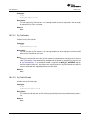
System Tick (SysTick)
Introduction . . . . . . .
API Functions . . . . .
Programming Example
.
.
.
.
.
.
.
.
.
.
.
.
.
.
.
.
.
.
.
.
.
.
.
.
.
.
.
.
.
.
.
.
.
.
.
.
.
.
.
.
.
.
.
.
.
.
.
.
.
.
.
.
.
.
.
.
.
.
.
.
.
.
.
.
.
.
.
.
.
.
.
.
.
.
.
.
.
.
.
.
.
.
.
.
.
.
.
.
.
.
.
.
.
.
.
.
.
.
.
.
.
.
.
.
.
.
.
.
.
.
.
.
.
.
.
.
.
.
.
.
.
.
.
.
.
.
.
.
.
.
.
.
.
.
.
.
.
.
.
.
.
.
.
.
.
.
.
.
.
.
.
.
.
.
.
.
.
.
.
.
.
.
.
.
.
.
.
.
.
.
.
.
275
275
275
279
21
21.1
21.2
21.3
Timer . . . . . . . . . .
Introduction . . . . . . .
API Functions . . . . .
Programming Example
.
.
.
.
.
.
.
.
.
.
.
.
.
.
.
.
.
.
.
.
.
.
.
.
.
.
.
.
.
.
.
.
.
.
.
.
.
.
.
.
.
.
.
.
.
.
.
.
.
.
.
.
.
.
.
.
.
.
.
.
.
.
.
.
.
.
.
.
.
.
.
.
.
.
.
.
.
.
.
.
.
.
.
.
.
.
.
.
.
.
.
.
.
.
.
.
.
.
.
.
.
.
.
.
.
.
.
.
.
.
.
.
.
.
.
.
.
.
.
.
.
.
.
.
.
.
.
.
.
.
.
.
.
.
.
.
.
.
.
.
.
.
.
.
.
.
.
.
.
.
.
.
.
.
.
.
.
.
.
.
.
.
.
.
.
.
.
.
.
.
.
.
281
281
281
293
22
22.1
22.2
22.3
UART . . . . . . . . . .
Introduction . . . . . . .
API Functions . . . . .
Programming Example
.
.
.
.
.
.
.
.
.
.
.
.
.
.
.
.
.
.
.
.
.
.
.
.
.
.
.
.
.
.
.
.
.
.
.
.
.
.
.
.
.
.
.
.
.
.
.
.
.
.
.
.
.
.
.
.
.
.
.
.
.
.
.
.
.
.
.
.
.
.
.
.
.
.
.
.
.
.
.
.
.
.
.
.
.
.
.
.
.
.
.
.
.
.
.
.
.
.
.
.
.
.
.
.
.
.
.
.
.
.
.
.
.
.
.
.
.
.
.
.
.
.
.
.
.
.
.
.
.
.
.
.
.
.
.
.
.
.
.
.
.
.
.
.
.
.
.
.
.
.
.
.
.
.
.
.
.
.
.
.
.
.
.
.
.
.
.
.
.
.
.
.
295
295
295
315
23
23.1
23.2
23.3
uDMA Controller . . .
Introduction . . . . . . .
API Functions . . . . .
Programming Example
.
.
.
.
.
.
.
.
.
.
.
.
.
.
.
.
.
.
.
.
.
.
.
.
.
.
.
.
.
.
.
.
.
.
.
.
.
.
.
.
.
.
.
.
.
.
.
.
.
.
.
.
.
.
.
.
.
.
.
.
.
.
.
.
.
.
.
.
.
.
.
.
.
.
.
.
.
.
.
.
.
.
.
.
.
.
.
.
.
.
.
.
.
.
.
.
.
.
.
.
.
.
.
.
.
.
.
.
.
.
.
.
.
.
.
.
.
.
.
.
.
.
.
.
.
.
.
.
.
.
.
.
.
.
.
.
.
.
.
.
.
.
.
.
.
.
.
.
.
.
.
.
.
.
.
.
.
.
.
.
.
.
.
.
.
.
.
.
.
.
.
.
317
317
318
334
4
Table of Contents
.
.
.
.
.
.
.
.
.
.
.
.
.
.
.
.
.
.
.
.
.
.
.
.
.
.
.
.
SW-DRL-UG-5450 - December 02, 2009
www.ti.com
Table of Contents
24
24.1
24.2
24.3
24.4
USB Controller . . . . . . . . . . . .
Introduction . . . . . . . . . . . . . . .
Using USB with the uDMA Controller
API Functions . . . . . . . . . . . . .
Programming Example . . . . . . . .
.
.
.
.
.
.
.
.
.
.
.
.
.
.
.
.
.
.
.
.
.
.
.
.
.
.
.
.
.
.
.
.
.
.
.
.
.
.
.
.
.
.
.
.
.
.
.
.
.
.
.
.
.
.
.
.
.
.
.
.
.
.
.
.
.
.
.
.
.
.
.
.
.
.
.
.
.
.
.
.
.
.
.
.
.
.
.
.
.
.
.
.
.
.
.
.
.
.
.
.
.
.
.
.
.
.
.
.
.
.
.
.
.
.
.
.
.
.
.
.
.
.
.
.
.
.
.
.
.
.
.
.
.
.
.
.
.
.
.
.
.
.
.
.
.
.
.
.
.
.
.
.
.
.
.
.
.
.
.
.
.
.
.
.
.
.
.
.
.
.
.
.
.
.
.
337
337
337
341
375
25
25.1
25.2
25.3
Watchdog Timer . . .
Introduction . . . . . . .
API Functions . . . . .
Programming Example
.
.
.
.
.
.
.
.
.
.
.
.
.
.
.
.
.
.
.
.
.
.
.
.
.
.
.
.
.
.
.
.
.
.
.
.
.
.
.
.
.
.
.
.
.
.
.
.
.
.
.
.
.
.
.
.
.
.
.
.
.
.
.
.
.
.
.
.
.
.
.
.
.
.
.
.
.
.
.
.
.
.
.
.
.
.
.
.
.
.
.
.
.
.
.
.
.
.
.
.
.
.
.
.
.
.
.
.
.
.
.
.
.
.
.
.
.
.
.
.
.
.
.
.
.
.
.
.
.
.
.
.
.
.
.
.
.
.
.
.
.
.
.
.
.
.
.
.
.
.
.
.
.
.
.
.
.
.
.
.
.
.
.
.
.
.
.
.
.
.
.
.
377
377
377
385
26
26.1
26.2
26.3
26.4
Using the ROM . .
Introduction . . . . .
Direct ROM Calls .
Mapped ROM Calls
Firmware Update .
.
.
.
.
.
.
.
.
.
.
.
.
.
.
.
.
.
.
.
.
.
.
.
.
.
.
.
.
.
.
.
.
.
.
.
.
.
.
.
.
.
.
.
.
.
.
.
.
.
.
.
.
.
.
.
.
.
.
.
.
.
.
.
.
.
.
.
.
.
.
.
.
.
.
.
.
.
.
.
.
.
.
.
.
.
.
.
.
.
.
.
.
.
.
.
.
.
.
.
.
.
.
.
.
.
.
.
.
.
.
.
.
.
.
.
.
.
.
.
.
.
.
.
.
.
.
.
.
.
.
.
.
.
.
.
.
.
.
.
.
.
.
.
.
.
.
.
.
.
.
.
.
.
.
.
.
.
.
.
.
.
.
.
.
.
.
.
.
.
.
.
.
.
.
.
.
.
.
.
.
.
.
.
.
.
.
.
.
.
.
.
.
.
.
.
.
.
.
.
.
.
.
.
.
.
.
.
.
.
.
.
.
.
.
.
387
387
387
388
389
27
Error Handling . . . . . . . . . . . . . . . . . . . . . . . . . . . . . . . . . . . . . . . . . . . . . . . 391
.
.
.
.
.
.
.
.
.
.
IMPORTANT NOTICE . . . . . . . . . . . . . . . . . . . . . . . . . . . . . . . . . . . . . . . . . . . . . . . 392
SW-DRL-UG-5450 - December 02, 2009
Table of Contents
5
Table of Contents
6
Table of Contents
www.ti.com
SW-DRL-UG-5450 - December 02, 2009
www.ti.com
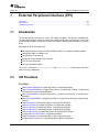
1
Introduction
Introduction
The Texas Instruments® Stellaris® Peripheral Driver Library is a set of drivers for accessing the
peripherals found on the Stellaris family of ARM® Cortex™-M3 based microcontrollers. While they
are not drivers in the pure operating system sense (that is, they do not have a common interface
and do not connect into a global device driver infrastructure), they do provide a mechanism that
makes it easy to use the device’s peripherals.
The capabilities and organization of the drivers are governed by the following design goals:
They are written entirely in C except where absolutely not possible.
They demonstrate how to use the peripheral in its common mode of operation.
They are easy to understand.
They are reasonably efficient in terms of memory and processor usage.
They are as self-contained as possible.
Where possible, computations that can be performed at compile time are done there instead
of at run time.
They can be built with more than one tool chain.
Some consequences of these design goals are:
The drivers are not necessarily as efficient as they could be (from a code size and/or execution
speed point of view). While the most efficient piece of code for operating a peripheral would be
written in assembly and custom tailored to the specific requirements of the application, further
size optimizations of the drivers would make them more difficult to understand.
The drivers do not support the full capabilities of the hardware. Some of the peripherals
provide complex capabilities which can not be utilized by the drivers in this library, though
the existing code can be used as a reference upon which to add support for the additional
capabilities.
The APIs have a means of removing all error checking code. Since the error checking is
usually only useful during initial program development, it can be removed to improve code size
and speed.
For many applications, the drivers can be used as is. But in some cases, the drivers will have to be
enhanced or rewritten in order to meet the functionality, memory, or processing requirements of the
application. If so, the existing driver can be used as a reference on how to operate the peripheral.
The following tool chains are supported:
Keil™ RealView® Microcontroller Development Kit
CodeSourcery Sourcery G++ for Stellaris EABI
IAR Embedded Workbench®
Code Red Technologies tools
Source Code Overview
The following is an overview of the organization of the peripheral driver library source code.
SW-DRL-UG-5450 - December 02, 2009
Introduction
7
Introduction
8
www.ti.com
EULA.txt
The full text of the End User License Agreement that covers the use of this
software package.
driverlib/
This directory contains the source code for the drivers.
hw_*.h
Header files, one per peripheral, that describe all the registers and the bit
fields within those registers for each peripheral. These header files are used
by the drivers to directly access a peripheral, and can be used by application
code to bypass the peripheral driver library API.
inc/
This directory holds the part specific header files used for the direct register
access programming model.
makedefs
A set of definitions used by make files.
Introduction
SW-DRL-UG-5450 - December 02, 2009
www.ti.com
2
Programming Model
Programming Model
Introduction . . . . . . . . . . . . . . . . . . . . . . . . . . . . . . . . . . . . . . . . . . . . . . . . . . . . . . . . . . . . . . . . . . . . . . . . . . . . . . . . . . . . . . . . . . . . . . . 9
Direct Register Access Model . . . . . . . . . . . . . . . . . . . . . . . . . . . . . . . . . . . . . . . . . . . . . . . . . . . . . . . . . . . . . . . . . . . . . . . . . . . . . 9
Software Driver Model . . . . . . . . . . . . . . . . . . . . . . . . . . . . . . . . . . . . . . . . . . . . . . . . . . . . . . . . . . . . . . . . . . . . . . . . . . . . . . . . . . . 10
Combining The Models . . . . . . . . . . . . . . . . . . . . . . . . . . . . . . . . . . . . . . . . . . . . . . . . . . . . . . . . . . . . . . . . . . . . . . . . . . . . . . . . . . 11
2.1
Introduction
The peripheral driver library provides support for two programming models: the direct register access model and the software driver model. Each model can be used independently, or combined,
based on the needs of the application or the programming environment desired by the developer.
Each programming model has advantages and disadvantages. Use of the direct register access
model will generally result in smaller and more efficient code than using the software driver model.
However, the direct register access model does require detailed knowledge of the operation of
each register, bit field, their interactions, and any sequencing required for proper operation of the
peripheral; the developer is insulated from these details by the software driver model, generally
requiring less time to develop applications.
2.2
Direct Register Access Model
In the direct register access model, the peripherals are programmed by the application by writing
values directly into the peripheral’s registers. A set of macros is provided that simplifies this process.
These macros are stored in part-specific header files contained in the inc directory; the name of the
header file matches the part number (for example, the header file for the LM3S6965 microcontroller
is inc/lm3s6965.h). By including the header file that matches the part being used, macros are
available for accessing all registers on that part, as well as all bit fields within those registers. No
macros are available for registers that do not exist on the part in question, making it difficult to
access registers that do not exist.
The defines used by the direct register access model follow a naming convention that makes it
easier to know how to use a particular macro. The rules are as follows:
Values that end in _R are used to access the value of a register. For example, SSI0_CR0_R
is used to access the CR0 register in the SSI0 module.
Values that end in _M represent the mask for a multi-bit field in a register. If the value
placed in the multi-bit field is a number, there will be a macro with the same base name
but ending with _S (for example, SSI_CR0_SCR_M and SSI_CR0_SCR_S). If the value
placed into the multi-bit field is an enumeration, then there will be a set of macros with
the same base name but ending with identifiers for the various enumeration values (for
example, the SSI_CR0_FRF_M macro defines the bit field, and the SSI_CR0_FRF_NMW,
SSI_CR0_FRF_TI, and SSI_CR0_FRF_MOTO macros provide the enumerations for the bit
field).
Values that end in _S represent the number of bits to shift a value in order to align it with a
multi-bit field. These values will match the macro with the same base name but ending with
_M.
SW-DRL-UG-5450 - December 02, 2009
Programming Model
9
Software Driver Model
www.ti.com
All other macros represent the value of a bit field.
All register name macros start with the module name and instance number (for example, SSI0
for the first SSI module) and are followed by the name of the register as it appears in the data
sheet (for example, the CR0 register in the data sheet results in SSI0_CR0_R).
All register bit fields start with the module name, followed by the register name, and then
followed by the bit field name as it appears in the data sheet. For example, the SCR bit field in
the CR0 register in the SSI module will be identified by SSI_CR0_SCR.... In the case where
the bit field is a single bit, there will be nothing further (for example, SSI_CR0_SPH is a single
bit in the CR0 register). If the bit field is more than a single bit, there will be a mask value (_M)
and either a shift (_S) if the bit field contains a number or a set of enumerations if not.
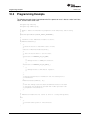
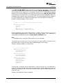
Given these definitions, the CR0 register can be programmed as follows:
SSI0_CR0_R = ((5 << SSI_CR0_SCR_S) | SSI_CR0_SPH | SSI_CR0_SPO |
SSI_CR0_FRF_MOTO | SSI_CR0_DSS_8);
Alternatively, the following has the same effect (although it is not as easy to understand):
SSI0_CR0_R = 0x000005c7;
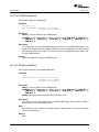
Extracting the value of the SCR field from the CR0 register is as follows:
ulValue = (SSI0_CR0_R & SSI_CR0_SCR_M) >> SSI0_CR0_SCR_S;
The GPIO modules have many registers that do not have bit field definitions. For these registers,
the register bits represent the individual GPIO pins; so bit zero in these registers corresponds to
the Px0 pin on the part (where x is replaced by a GPIO module letter), bit one corresponds to the
Px1 pin, and so on.
The blinky example for each board utilizes the direct register access model to blink the on-board
LED.
Note:
The hw_∗.h header files that are used by the drivers in the library contain many of the same
definitions as the header files used for direct register access. As such, the two can not be included into the same source file without the compiler producing warnings about the redefinition
of symbols.
2.3
Software Driver Model
In the software driver model, the API provided by the peripheral driver library is used by applications to control the peripherals. Since these drivers provide complete control of the peripherals in
their normal mode of operation, it is possible to write an entire application without direct access
to the hardware. This provides for rapid development of the application without requiring detailed
knowledge of how to program the peripherals.
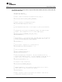
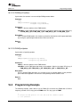
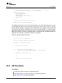
Corresponding to the direct register access model example, the following will also program the CR0
register in the SSI module (though that fact is hidden by the API):
10
Programming Model
SW-DRL-UG-5450 - December 02, 2009
www.ti.com
Combining The Models
SSIConfigSetExpClk(SSI0_BASE, 50000000, SSI_FRF_MOTO_MODE_3,
SSI_MODE_MASTER, 1000000, 8);
The resulting value in the CR0 register might not be exactly the same since SSIConfigSetExpClk()
may compute a different value for the SCR bit field than what was used in the direct register access
model example.
All example applications other than blinky utilize the software driver model.
The drivers in the peripheral driver library are described in the remaining chapters in this document.
They combine to form the software driver model.
2.4
Combining The Models
The direct register access model and software driver model can be utilized together in a single
application. This allows the most appropriate model to be used in any particular situation within the
application; for example, the software driver model can be used to configure the peripherals (since
this is not performance critical) and the direct register access model can be used for operation of
the peripheral (which may be more performance critical). Or, the software driver model can be used
for peripherals that are not performance critical (such as a UART used for data logging) and the
direct register access model for performance critical peripherals (such as the ADC module used to
capture real-time analog data).
SW-DRL-UG-5450 - December 02, 2009
Programming Model
11
Combining The Models
12
Programming Model
www.ti.com
SW-DRL-UG-5450 - December 02, 2009
www.ti.com
3
Analog Comparator
Analog Comparator
Introduction . . . . . . . . . . . . . . . . . . . . . . . . . . . . . . . . . . . . . . . . . . . . . . . . . . . . . . . . . . . . . . . . . . . . . . . . . . . . . . . . . . . . . . . . . . . . . . 13
API Functions . . . . . . . . . . . . . . . . . . . . . . . . . . . . . . . . . . . . . . . . . . . . . . . . . . . . . . . . . . . . . . . . . . . . . . . . . . . . . . . . . . . . . . . . . . . . 13
Programming Example . . . . . . . . . . . . . . . . . . . . . . . . . . . . . . . . . . . . . . . . . . . . . . . . . . . . . . . . . . . . . . . . . . . . . . . . . . . . . . . . . . . 19
3.1
Introduction
The comparator API provides a set of functions for dealing with the analog comparators. A comparator can compare a test voltage against individual external reference voltage, a shared single
external reference voltage, or a shared internal reference voltage. It can provide its output to a
device pin, acting as a replacement for an analog comparator on the board, or it can be used to
signal the application via interrupts or triggers to the ADC to cause it to start capturing a sample
sequence. The interrupt generation and ADC triggering logic is separate, so that an interrupt can
be generated on a rising edge and the ADC triggered on a falling edge (for example).
This driver is contained in driverlib/comp.c, with driverlib/comp.h containing the API
definitions for use by applications.
3.2
API Functions
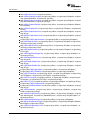
Functions
void ComparatorConfigure (unsigned long ulBase, unsigned long ulComp, unsigned long ulConfig)
void ComparatorIntClear (unsigned long ulBase, unsigned long ulComp)
void ComparatorIntDisable (unsigned long ulBase, unsigned long ulComp)
void ComparatorIntEnable (unsigned long ulBase, unsigned long ulComp)
void ComparatorIntRegister (unsigned long ulBase, unsigned long ulComp, void
(∗pfnHandler)(void))
tBoolean ComparatorIntStatus (unsigned long ulBase, unsigned long ulComp, tBoolean
bMasked)
void ComparatorIntUnregister (unsigned long ulBase, unsigned long ulComp)
void ComparatorRefSet (unsigned long ulBase, unsigned long ulRef)
tBoolean ComparatorValueGet (unsigned long ulBase, unsigned long ulComp)
3.2.1
Detailed Description
The comparator API is fairly simple, like the comparators themselves. There are functions for
configuring a comparator and reading its output (ComparatorConfigure(), ComparatorRefSet() and
ComparatorValueGet()) and functions for dealing with an interrupt handler for the comparator (ComparatorIntRegister(), ComparatorIntUnregister(), ComparatorIntEnable(), ComparatorIntDisable(),
ComparatorIntStatus(), and ComparatorIntClear()).
SW-DRL-UG-5450 - December 02, 2009
Analog Comparator
13
API Functions
www.ti.com
3.2.2
Function Documentation
3.2.2.1
ComparatorConfigure
Configures a comparator.
Prototype:
void
ComparatorConfigure(unsigned long ulBase,
unsigned long ulComp,
unsigned long ulConfig)
Parameters:
ulBase is the base address of the comparator module.
ulComp is the index of the comparator to configure.
ulConfig is the configuration of the comparator.
Description:
This function will configure a comparator. The ulConfig parameter is the result of a logical
OR operation between the COMP_TRIG_xxx, COMP_INT_xxx, COMP_ASRCP_xxx, and
COMP_OUTPUT_xxx values.
The COMP_TRIG_xxx term can take on the following values:
COMP_TRIG_NONE to have no trigger to the ADC.
COMP_TRIG_HIGH to trigger the ADC when the comparator output is high.
COMP_TRIG_LOW to trigger the ADC when the comparator output is low.
COMP_TRIG_FALL to trigger the ADC when the comparator output goes low.
COMP_TRIG_RISE to trigger the ADC when the comparator output goes high.
COMP_TRIG_BOTH to trigger the ADC when the comparator output goes low or high.
The COMP_INT_xxx term can take on the following values:
COMP_INT_HIGH to generate an interrupt when the comparator output is high.
COMP_INT_LOW to generate an interrupt when the comparator output is low.
COMP_INT_FALL to generate an interrupt when the comparator output goes low.
COMP_INT_RISE to generate an interrupt when the comparator output goes high.
COMP_INT_BOTH to generate an interrupt when the comparator output goes low or high.
The COMP_ASRCP_xxx term can take on the following values:
COMP_ASRCP_PIN to use the dedicated Comp+ pin as the reference voltage.
COMP_ASRCP_PIN0 to use the Comp0+ pin as the reference voltage (this the same as
COMP_ASRCP_PIN for the comparator 0).
COMP_ASRCP_REF to use the internally generated voltage as the reference voltage.
The COMP_OUTPUT_xxx term can take on the following values:
COMP_OUTPUT_NORMAL to enable a non-inverted output from the comparator to a
device pin.
COMP_OUTPUT_INVERT to enable an inverted output from the comparator to a device
pin.
14
Analog Comparator
SW-DRL-UG-5450 - December 02, 2009
www.ti.com
API Functions
COMP_OUTPUT_NONE
is
COMP_OUTPUT_NORMAL.
deprecated
and
behaves
the
same
as
Returns:
None.
3.2.2.2
ComparatorIntClear
Clears a comparator interrupt.
Prototype:
void
ComparatorIntClear(unsigned long ulBase,
unsigned long ulComp)
Parameters:
ulBase is the base address of the comparator module.
ulComp is the index of the comparator.
Description:
The comparator interrupt is cleared, so that it no longer asserts. This must be done in the
interrupt handler to keep it from being called again immediately upon exit. Note that for a level
triggered interrupt, the interrupt cannot be cleared until it stops asserting.
Note:
Since there is a write buffer in the Cortex-M3 processor, it may take several clock cycles before
the interrupt source is actually cleared. Therefore, it is recommended that the interrupt source
be cleared early in the interrupt handler (as opposed to the very last action) to avoid returning
from the interrupt handler before the interrupt source is actually cleared. Failure to do so may
result in the interrupt handler being immediately reentered (since NVIC still sees the interrupt
source asserted).
Returns:
None.
3.2.2.3
ComparatorIntDisable
Disables the comparator interrupt.
Prototype:
void
ComparatorIntDisable(unsigned long ulBase,
unsigned long ulComp)
Parameters:
ulBase is the base address of the comparator module.
ulComp is the index of the comparator.
Description:
This function disables generation of an interrupt from the specified comparator. Only comparators whose interrupts are enabled can be reflected to the processor.
SW-DRL-UG-5450 - December 02, 2009
Analog Comparator
15
API Functions
www.ti.com
Returns:
None.
3.2.2.4
ComparatorIntEnable
Enables the comparator interrupt.
Prototype:
void
ComparatorIntEnable(unsigned long ulBase,
unsigned long ulComp)
Parameters:
ulBase is the base address of the comparator module.
ulComp is the index of the comparator.
Description:
This function enables generation of an interrupt from the specified comparator. Only comparators whose interrupts are enabled can be reflected to the processor.
Returns:
None.
3.2.2.5
ComparatorIntRegister
Registers an interrupt handler for the comparator interrupt.
Prototype:
void
ComparatorIntRegister(unsigned long ulBase,
unsigned long ulComp,
void (*pfnHandler)(void))
Parameters:
ulBase is the base address of the comparator module.
ulComp is the index of the comparator.
pfnHandler is a pointer to the function to be called when the comparator interrupt occurs.
Description:
This sets the handler to be called when the comparator interrupt occurs. This will enable the
interrupt in the interrupt controller; it is the interrupt-handler’s responsibility to clear the interrupt
source via ComparatorIntClear().
See also:
IntRegister() for important information about registering interrupt handlers.
Returns:
None.
16
Analog Comparator
SW-DRL-UG-5450 - December 02, 2009
www.ti.com
3.2.2.6
API Functions
ComparatorIntStatus
Gets the current interrupt status.
Prototype:
tBoolean
ComparatorIntStatus(unsigned long ulBase,
unsigned long ulComp,
tBoolean bMasked)
Parameters:
ulBase is the base address of the comparator module.
ulComp is the index of the comparator.
bMasked is false if the raw interrupt status is required and true if the masked interrupt status
is required.
Description:
This returns the interrupt status for the comparator. Either the raw or the masked interrupt
status can be returned.
Returns:
true if the interrupt is asserted and false if it is not asserted.
3.2.2.7
ComparatorIntUnregister
Unregisters an interrupt handler for a comparator interrupt.
Prototype:
void
ComparatorIntUnregister(unsigned long ulBase,
unsigned long ulComp)
Parameters:
ulBase is the base address of the comparator module.
ulComp is the index of the comparator.
Description:
This function will clear the handler to be called when a comparator interrupt occurs. This will
also mask off the interrupt in the interrupt controller so that the interrupt handler no longer is
called.
See also:
IntRegister() for important information about registering interrupt handlers.
Returns:
None.
3.2.2.8
ComparatorRefSet
Sets the internal reference voltage.
SW-DRL-UG-5450 - December 02, 2009
Analog Comparator
17
API Functions
www.ti.com
Prototype:
void
ComparatorRefSet(unsigned long ulBase,
unsigned long ulRef)
Parameters:
ulBase is the base address of the comparator module.
ulRef is the desired reference voltage.
Description:
This function will set the internal reference voltage value. The voltage is specified as one of
the following values:
COMP_REF_OFF to turn off the reference voltage
COMP_REF_0V to set the reference voltage to 0 V
COMP_REF_0_1375V to set the reference voltage to 0.1375 V
COMP_REF_0_275V to set the reference voltage to 0.275 V
COMP_REF_0_4125V to set the reference voltage to 0.4125 V
COMP_REF_0_55V to set the reference voltage to 0.55 V
COMP_REF_0_6875V to set the reference voltage to 0.6875 V
COMP_REF_0_825V to set the reference voltage to 0.825 V
COMP_REF_0_928125V to set the reference voltage to 0.928125 V
COMP_REF_0_9625V to set the reference voltage to 0.9625 V
COMP_REF_1_03125V to set the reference voltage to 1.03125 V
COMP_REF_1_134375V to set the reference voltage to 1.134375 V
COMP_REF_1_1V to set the reference voltage to 1.1 V
COMP_REF_1_2375V to set the reference voltage to 1.2375 V
COMP_REF_1_340625V to set the reference voltage to 1.340625 V
COMP_REF_1_375V to set the reference voltage to 1.375 V
COMP_REF_1_44375V to set the reference voltage to 1.44375 V
COMP_REF_1_5125V to set the reference voltage to 1.5125 V
COMP_REF_1_546875V to set the reference voltage to 1.546875 V
COMP_REF_1_65V to set the reference voltage to 1.65 V
COMP_REF_1_753125V to set the reference voltage to 1.753125 V
COMP_REF_1_7875V to set the reference voltage to 1.7875 V
COMP_REF_1_85625V to set the reference voltage to 1.85625 V
COMP_REF_1_925V to set the reference voltage to 1.925 V
COMP_REF_1_959375V to set the reference voltage to 1.959375 V
COMP_REF_2_0625V to set the reference voltage to 2.0625 V
COMP_REF_2_165625V to set the reference voltage to 2.165625 V
COMP_REF_2_26875V to set the reference voltage to 2.26875 V
COMP_REF_2_371875V to set the reference voltage to 2.371875 V
Returns:
None.
18
Analog Comparator
SW-DRL-UG-5450 - December 02, 2009
www.ti.com
3.2.2.9
Programming Example
ComparatorValueGet
Gets the current comparator output value.
Prototype:
tBoolean
ComparatorValueGet(unsigned long ulBase,
unsigned long ulComp)
Parameters:
ulBase is the base address of the comparator module.
ulComp is the index of the comparator.
Description:
This function retrieves the current value of the comparator output.
Returns:
Returns true if the comparator output is high and false if the comparator output is low.
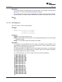
3.3
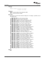
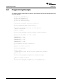
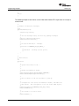
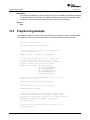
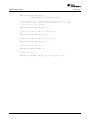
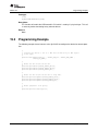
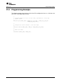
Programming Example
The following example shows how to use the comparator API to configure the comparator and read
its value.
//
// Configure the internal voltage reference.
//
ComparatorRefSet(COMP_BASE, COMP_REF_1_65V);
//
// Configure a comparator.
//
ComparatorConfigure(COMP_BASE, 0,
(COMP_TRIG_NONE | COMP_INT_BOTH |
COMP_ASRCP_REF | COMP_OUTPUT_NONE));
//
// Delay for some time...
//
//
// Read the comparator output value.
//
ComparatorValueGet(COMP_BASE, 0);
SW-DRL-UG-5450 - December 02, 2009
Analog Comparator
19
Programming Example
20
Analog Comparator
www.ti.com
SW-DRL-UG-5450 - December 02, 2009
www.ti.com
4
Analog to Digital Converter (ADC)
Analog to Digital Converter (ADC)
Introduction . . . . . . . . . . . . . . . . . . . . . . . . . . . . . . . . . . . . . . . . . . . . . . . . . . . . . . . . . . . . . . . . . . . . . . . . . . . . . . . . . . . . . . . . . . . . . . 21
API Functions . . . . . . . . . . . . . . . . . . . . . . . . . . . . . . . . . . . . . . . . . . . . . . . . . . . . . . . . . . . . . . . . . . . . . . . . . . . . . . . . . . . . . . . . . . . . 22
Programming Example . . . . . . . . . . . . . . . . . . . . . . . . . . . . . . . . . . . . . . . . . . . . . . . . . . . . . . . . . . . . . . . . . . . . . . . . . . . . . . . . . . . 37
4.1
Introduction
The analog to digital converter (ADC) API provides a set of functions for dealing with the ADC.
Functions are provided to configure the sample sequencers, read the captured data, register a
sample sequence interrupt handler, and handle interrupt masking/clearing.
The ADC supports up to eight input channels plus an internal temperature sensor. Four sampling
sequences, each with configurable trigger events, can be captured. The first sequence will capture
up to eight samples, the second and third sequences will capture up to four samples, and the fourth
sequence will capture a single sample. Each sample can be the same channel, different channels,
or any combination in any order.
The sample sequences have configurable priorities that determine the order in which they are captured when multiple triggers occur simultaneously. The highest priority sequence that is currently
triggered will be sampled. Care must be taken with triggers that occur frequently (such as the
“always” trigger); if their priority is too high it is possible to starve the lower priority sequences.
Beginning with Rev C0 of the Stellaris microcontroller, hardware oversampling of the ADC data is
available for improved accuracy. An oversampling factor of 2x, 4x, 8x, 16x, 32x, and 64x is supported, but reduces the throughput of the ADC by a corresponding factor. Hardware oversampling
is applied uniformly across all sample sequences.
Software oversampling of the ADC data is also available (even when hardware oversampling is
available). An oversampling factor of 2x, 4x, and 8x is supported, but reduces the depth of the
sample sequences by a corresponding amount. For example, the first sample sequence will capture
eight samples; in 4x oversampling mode it can only capture two samples since the first four samples
are used over the first oversampled value and the second four samples are used for the second
oversampled value. The amount of software oversampling is configured on a per sample sequence
basis.
A more sophisticated software oversampling can be used to eliminate the reduction of the sample
sequence depth. By increasing the ADC trigger rate by 4x (for example) and averaging four triggers worth of data, 4x oversampling is achieved without any loss of sample sequence capability.
In this case, an increase in the number of ADC triggers (and presumably ADC interrupts) is the
consequence. Since this requires adjustments outside of the ADC driver itself, this is not directly
supported by the driver (though nothing in the driver prevents it). The software oversampling APIs
should not be used in this case.
This driver is contained in driverlib/adc.c, with driverlib/adc.h containing the API definitions for use by applications.
SW-DRL-UG-5450 - December 02, 2009
Analog to Digital Converter (ADC)
21
API Functions
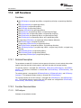
4.2
www.ti.com
API Functions
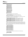
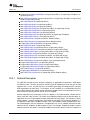
Functions
void ADCComparatorConfigure (unsigned long ulBase, unsigned long ulComp, unsigned long
ulConfig)
void ADCComparatorIntClear (unsigned long ulBase, unsigned long ulStatus)
void ADCComparatorIntDisable (unsigned long ulBase, unsigned long ulSequenceNum)
void ADCComparatorIntEnable (unsigned long ulBase, unsigned long ulSequenceNum)
unsigned long ADCComparatorIntStatus (unsigned long ulBase)
void ADCComparatorRegionSet (unsigned long ulBase, unsigned long ulComp, unsigned long
ulLowRef, unsigned long ulHighRef)
void ADCComparatorReset (unsigned long ulBase, unsigned long ulComp, tBoolean bTrigger,
tBoolean bInterrupt)
void ADCHardwareOversampleConfigure (unsigned long ulBase, unsigned long ulFactor)
void ADCIntClear (unsigned long ulBase, unsigned long ulSequenceNum)
void ADCIntDisable (unsigned long ulBase, unsigned long ulSequenceNum)
void ADCIntEnable (unsigned long ulBase, unsigned long ulSequenceNum)
void ADCIntRegister (unsigned long ulBase, unsigned long ulSequenceNum, void
(∗pfnHandler)(void))
unsigned long ADCIntStatus (unsigned long ulBase, unsigned long ulSequenceNum, tBoolean
bMasked)
void ADCIntUnregister (unsigned long ulBase, unsigned long ulSequenceNum)
void ADCProcessorTrigger (unsigned long ulBase, unsigned long ulSequenceNum)
void ADCSequenceConfigure (unsigned long ulBase, unsigned long ulSequenceNum, unsigned long ulTrigger, unsigned long ulPriority)
long ADCSequenceDataGet (unsigned long ulBase, unsigned long ulSequenceNum, unsigned long ∗pulBuffer)
void ADCSequenceDisable (unsigned long ulBase, unsigned long ulSequenceNum)
void ADCSequenceEnable (unsigned long ulBase, unsigned long ulSequenceNum)
long ADCSequenceOverflow (unsigned long ulBase, unsigned long ulSequenceNum)
void ADCSequenceOverflowClear (unsigned long ulBase, unsigned long ulSequenceNum)
void ADCSequenceStepConfigure (unsigned long ulBase, unsigned long ulSequenceNum,
unsigned long ulStep, unsigned long ulConfig)
long ADCSequenceUnderflow (unsigned long ulBase, unsigned long ulSequenceNum)
void ADCSequenceUnderflowClear (unsigned long ulBase, unsigned long ulSequenceNum)
void ADCSoftwareOversampleConfigure (unsigned long ulBase, unsigned long ulSequenceNum, unsigned long ulFactor)
void ADCSoftwareOversampleDataGet (unsigned long ulBase, unsigned long ulSequenceNum, unsigned long ∗pulBuffer, unsigned long ulCount)
void ADCSoftwareOversampleStepConfigure (unsigned long ulBase, unsigned long ulSequenceNum, unsigned long ulStep, unsigned long ulConfig)
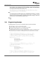
4.2.1
Detailed Description
The analog to digital converter API is broken into three groups of functions: those that deal with
the sample sequences, those that deal with the processor trigger, and those that deal with interrupt
handling.
22
Analog to Digital Converter (ADC)
SW-DRL-UG-5450 - December 02, 2009
www.ti.com
API Functions
The sample sequences are configured with ADCSequenceConfigure() and ADCSequenceStepConfigure(). They are enabled and disabled with ADCSequenceEnable() and ADCSequenceDisable(). The captured data is obtained with ADCSequenceDataGet(). Sample sequence FIFO overflow and underflow is managed with ADCSequenceOverflow(), ADCSequenceOverflowClear(), ADCSequenceUnderflow(), and ADCSequenceUnderflowClear().
Hardware oversampling of the ADC is controlled with ADCHardwareOversampleConfigure(). Software oversampling of the ADC is controlled with ADCSoftwareOversampleConfigure(), ADCSoftwareOversampleStepConfigure(), and ADCSoftwareOversampleDataGet().
The processor trigger is generated with ADCProcessorTrigger().
The interrupt handler for the ADC sample sequence interrupts are managed with ADCIntRegister()
and ADCIntUnregister(). The sample sequence interrupt sources are managed with ADCIntDisable(), ADCIntEnable(), ADCIntStatus(), and ADCIntClear().
4.2.2
Function Documentation
4.2.2.1
ADCComparatorConfigure
Configures an ADC digital comparator.
Prototype:
void
ADCComparatorConfigure(unsigned long ulBase,
unsigned long ulComp,
unsigned long ulConfig)
Parameters:
ulBase is the base address of the ADC module.
ulComp is the index of the comparator to configure.
ulConfig is the configuration of the comparator.
Description:
This function will configure a comparator. The ulConfig parameter is the result of a logical OR
operation between the ADC_COMP_TRIG_xxx, and ADC_COMP_INT_xxx values.
The ADC_COMP_TRIG_xxx term can take on the following values:
ADC_COMP_TRIG_NONE to never trigger PWM fault condition.
ADC_COMP_TRIG_LOW_ALWAYS to always trigger PWM fault condition when ADC output is in the low-band.
ADC_COMP_TRIG_LOW_ONCE to trigger PWM fault condition once when ADC output
transitions into the low-band.
ADC_COMP_TRIG_LOW_HALWAYS to always trigger PWM fault condition when ADC
output is in the low-band only if ADC output has been in the high-band since the last
trigger output.
ADC_COMP_TRIG_LOW_HONCE to trigger PWM fault condition once when ADC output
transitions into low-band only if ADC output has been in the high-band since the last trigger
output.
ADC_COMP_TRIG_MID_ALWAYS to always trigger PWM fault condition when ADC output is in the mid-band.
SW-DRL-UG-5450 - December 02, 2009
Analog to Digital Converter (ADC)
23
API Functions
www.ti.com
ADC_COMP_TRIG_MID_ONCE to trigger PWM fault condition once when ADC output
transitions into the mid-band.
ADC_COMP_TRIG_HIGH_ALWAYS to always trigger PWM fault condition when ADC output is in the high-band.
ADC_COMP_TRIG_HIGH_ONCE to trigger PWM fault condition once when ADC output
transitions into the high-band.
ADC_COMP_TRIG_HIGH_HALWAYS to always trigger PWM fault condition when ADC
output is in the high-band only if ADC output has been in the low-band since the last
trigger output.
ADC_COMP_TRIG_HIGH_HONCE to trigger PWM fault condition once when ADC output
transitions into high-band only if ADC output has been in the low-band since the last trigger
output.
The ADC_COMP_INT_xxx term can take on the following values:
ADC_COMP_INT_NONE to never generate ADC interrupt.
ADC_COMP_INT_LOW_ALWAYS to always generate ADC interrupt when ADC output is
in the low-band.
ADC_COMP_INT_LOW_ONCE to generate ADC interrupt once when ADC output transitions into the low-band.
ADC_COMP__INT_LOW_HALWAYS to always generate ADC interrupt when ADC output
is in the low-band only if ADC output has been in the high-band since the last trigger output.
ADC_COMP_INT_LOW_HONCE to generate ADC interrupt once when ADC output transitions into low-band only if ADC output has been in the high-band since the last trigger
output.
ADC_COMP_INT_MID_ALWAYS to always generate ADC interrupt when ADC output is
in the mid-band.
ADC_COMP_INT_MID_ONCE to generate ADC interrupt once when ADC output transitions into the mid-band.
ADC_COMP_INT_HIGH_ALWAYS to always generate ADC interrupt when ADC output is
in the high-band.
ADC_COMP_INT_HIGH_ONCE to generate ADC interrupt once when ADC output transitions into the high-band.
ADC_COMP_INT_HIGH_HALWAYS to always generate ADC interrupt when ADC output
is in the high-band only if ADC output has been in the low-band since the last trigger output.
ADC_COMP_INT_HIGH_HONCE to generate ADC interrupt once when ADC output transitions into high-band only if ADC output has been in the low-band since the last trigger
output.
Returns:
None.
4.2.2.2
ADCComparatorIntClear
Clears sample sequence comparator interrupt source.
Prototype:
void
ADCComparatorIntClear(unsigned long ulBase,
unsigned long ulStatus)
24
Analog to Digital Converter (ADC)
SW-DRL-UG-5450 - December 02, 2009
www.ti.com
API Functions
Parameters:
ulBase is the base address of the ADC module.
ulStatus is the bit-mapped interrupts status to clear.
Description:
The specified interrupt status is cleared.
Returns:
None.
4.2.2.3
ADCComparatorIntDisable
Disables a sample sequence comparator interrupt.
Prototype:
void
ADCComparatorIntDisable(unsigned long ulBase,
unsigned long ulSequenceNum)
Parameters:
ulBase is the base address of the ADC module.
ulSequenceNum is the sample sequence number.
Description:
This function disables the requested sample sequence comparator interrupt.
Returns:
None.
4.2.2.4
ADCComparatorIntEnable
Enables a sample sequence comparator interrupt.
Prototype:
void
ADCComparatorIntEnable(unsigned long ulBase,
unsigned long ulSequenceNum)
Parameters:
ulBase is the base address of the ADC module.
ulSequenceNum is the sample sequence number.
Description:
This function enables the requested sample sequence comparator interrupt.
Returns:
None.
SW-DRL-UG-5450 - December 02, 2009
Analog to Digital Converter (ADC)
25
API Functions
4.2.2.5
www.ti.com
ADCComparatorIntStatus
Gets the current comparator interrupt status.
Prototype:
unsigned long
ADCComparatorIntStatus(unsigned long ulBase)
Parameters:
ulBase is the base address of the ADC module.
Description:
This returns the digitial comparator interrupt status bits. This status is sequence agnostic.
Returns:
The current comparator interrupt status.
4.2.2.6
ADCComparatorRegionSet
Defines the ADC digital comparator regions.
Prototype:
void
ADCComparatorRegionSet(unsigned
unsigned
unsigned
unsigned
long
long
long
long
ulBase,
ulComp,
ulLowRef,
ulHighRef)
Parameters:
ulBase is the base address of the ADC module.
ulComp is the index of the comparator to configure.
ulLowRef is the reference point for the low/mid band threshold.
ulHighRef is the reference point for the mid/high band threshold.
Description:
The ADC digital comparator operation is based on three ADC value regions:
low-band is defined as any ADC value less than or equal to the ulLowRef value.
mid-band is defined as any ADC value greater than the ulLowRef value but less than or
equal to the ulHighRef value.
high-band is defined as any ADC value greater than the ulHighRef value.
Returns:
None.
4.2.2.7
ADCComparatorReset
Resets the current ADC digital comparator conditions.
26
Analog to Digital Converter (ADC)
SW-DRL-UG-5450 - December 02, 2009
www.ti.com
API Functions
Prototype:
void
ADCComparatorReset(unsigned
unsigned
tBoolean
tBoolean
long ulBase,
long ulComp,
bTrigger,
bInterrupt)
Parameters:
ulBase is the base address of the ADC module.
ulComp is the index of the comparator.
bTrigger is the flag to indicate reset of Trigger conditions.
bInterrupt is the flag to indicate reset of Interrupt conditions.
Description:
Because the digital comparator uses current and previous ADC values, this function is provide
to allow the comparator to be reset to its initial value to prevent stale data from being used
when a sequence is enabled.
Returns:
None.
4.2.2.8
ADCHardwareOversampleConfigure
Configures the hardware oversampling factor of the ADC.
Prototype:
void
ADCHardwareOversampleConfigure(unsigned long ulBase,
unsigned long ulFactor)
Parameters:
ulBase is the base address of the ADC module.
ulFactor is the number of samples to be averaged.
Description:
This function configures the hardware oversampling for the ADC, which can be used to provide
better resolution on the sampled data. Oversampling is accomplished by averaging multiple
samples from the same analog input. Six different oversampling rates are supported; 2x,
4x, 8x, 16x, 32x, and 64x. Specifying an oversampling factor of zero will disable hardware
oversampling.
Hardware oversampling applies uniformly to all sample sequencers. It does not reduce the
depth of the sample sequencers like the software oversampling APIs; each sample written into
the sample sequence FIFO is a fully oversampled analog input reading.
Enabling hardware averaging increases the precision of the ADC at the cost of throughput. For
example, enabling 4x oversampling reduces the throughput of a 250 Ksps ADC to 62.5 Ksps.
Note:
Hardware oversampling is available beginning with Rev C0 of the Stellaris microcontroller.
Returns:
None.
SW-DRL-UG-5450 - December 02, 2009
Analog to Digital Converter (ADC)
27
API Functions
4.2.2.9
www.ti.com
ADCIntClear
Clears sample sequence interrupt source.
Prototype:
void
ADCIntClear(unsigned long ulBase,
unsigned long ulSequenceNum)
Parameters:
ulBase is the base address of the ADC module.
ulSequenceNum is the sample sequence number.
Description:
The specified sample sequence interrupt is cleared, so that it no longer asserts. This must be
done in the interrupt handler to keep it from being called again immediately upon exit.
Note:
Since there is a write buffer in the Cortex-M3 processor, it may take several clock cycles before
the interrupt source is actually cleared. Therefore, it is recommended that the interrupt source
be cleared early in the interrupt handler (as opposed to the very last action) to avoid returning
from the interrupt handler before the interrupt source is actually cleared. Failure to do so may
result in the interrupt handler being immediately reentered (since NVIC still sees the interrupt
source asserted).
Returns:
None.
4.2.2.10 ADCIntDisable
Disables a sample sequence interrupt.
Prototype:
void
ADCIntDisable(unsigned long ulBase,
unsigned long ulSequenceNum)
Parameters:
ulBase is the base address of the ADC module.
ulSequenceNum is the sample sequence number.
Description:
This function disables the requested sample sequence interrupt.
Returns:
None.
4.2.2.11 ADCIntEnable
Enables a sample sequence interrupt.
28
Analog to Digital Converter (ADC)
SW-DRL-UG-5450 - December 02, 2009
www.ti.com
API Functions
Prototype:
void
ADCIntEnable(unsigned long ulBase,
unsigned long ulSequenceNum)
Parameters:
ulBase is the base address of the ADC module.
ulSequenceNum is the sample sequence number.
Description:
This function enables the requested sample sequence interrupt. Any outstanding interrupts
are cleared before enabling the sample sequence interrupt.
Returns:
None.
4.2.2.12 ADCIntRegister
Registers an interrupt handler for an ADC interrupt.
Prototype:
void
ADCIntRegister(unsigned long ulBase,
unsigned long ulSequenceNum,
void (*pfnHandler)(void))
Parameters:
ulBase is the base address of the ADC module.
ulSequenceNum is the sample sequence number.
pfnHandler is a pointer to the function to be called when the ADC sample sequence interrupt
occurs.
Description:
This function sets the handler to be called when a sample sequence interrupt occurs. This will
enable the global interrupt in the interrupt controller; the sequence interrupt must be enabled
with ADCIntEnable(). It is the interrupt handler’s responsibility to clear the interrupt source via
ADCIntClear().
See also:
IntRegister() for important information about registering interrupt handlers.
Returns:
None.
4.2.2.13 ADCIntStatus
Gets the current interrupt status.
Prototype:
unsigned long
ADCIntStatus(unsigned long ulBase,
SW-DRL-UG-5450 - December 02, 2009
Analog to Digital Converter (ADC)
29
API Functions
www.ti.com
unsigned long ulSequenceNum,
tBoolean bMasked)
Parameters:
ulBase is the base address of the ADC module.
ulSequenceNum is the sample sequence number.
bMasked is false if the raw interrupt status is required and true if the masked interrupt status
is required.
Description:
This returns the interrupt status for the specified sample sequence. Either the raw interrupt
status or the status of interrupts that are allowed to reflect to the processor can be returned.
Returns:
The current raw or masked interrupt status.
4.2.2.14 ADCIntUnregister
Unregisters the interrupt handler for an ADC interrupt.
Prototype:
void
ADCIntUnregister(unsigned long ulBase,
unsigned long ulSequenceNum)
Parameters:
ulBase is the base address of the ADC module.
ulSequenceNum is the sample sequence number.
Description:
This function unregisters the interrupt handler. This will disable the global interrupt in the
interrupt controller; the sequence interrupt must be disabled via ADCIntDisable().
See also:
IntRegister() for important information about registering interrupt handlers.
Returns:
None.
4.2.2.15 ADCProcessorTrigger
Causes a processor trigger for a sample sequence.
Prototype:
void
ADCProcessorTrigger(unsigned long ulBase,
unsigned long ulSequenceNum)
Parameters:
ulBase is the base address of the ADC module.
30
Analog to Digital Converter (ADC)
SW-DRL-UG-5450 - December 02, 2009
www.ti.com
API Functions
ulSequenceNum is the sample sequence number.
Description:
This function triggers a processor-initiated sample sequence if the sample sequence trigger is
configured to ADC_TRIGGER_PROCESSOR.
Returns:
None.
4.2.2.16 ADCSequenceConfigure
Configures the trigger source and priority of a sample sequence.
Prototype:
void
ADCSequenceConfigure(unsigned
unsigned
unsigned
unsigned
long
long
long
long
ulBase,
ulSequenceNum,
ulTrigger,
ulPriority)
Parameters:
ulBase is the base address of the ADC module.
ulSequenceNum is the sample sequence number.
ulTrigger is the trigger source that initiates the sample sequence; must be one of the
ADC_TRIGGER_∗ values.
ulPriority is the relative priority of the sample sequence with respect to the other sample
sequences.
Description:
This function configures the initiation criteria for a sample sequence. Valid sample sequences
range from zero to three; sequence zero will capture up to eight samples, sequences one and
two will capture up to four samples, and sequence three will capture a single sample. The
trigger condition and priority (with respect to other sample sequence execution) is set.
The ulTrigger parameter can take on the following values:
ADC_TRIGGER_PROCESSOR - A trigger generated by the processor, via the ADCProcessorTrigger() function.
ADC_TRIGGER_COMP0 - A trigger generated by the first analog comparator; configured
with ComparatorConfigure().
ADC_TRIGGER_COMP1 - A trigger generated by the second analog comparator; configured with ComparatorConfigure().
ADC_TRIGGER_COMP2 - A trigger generated by the third analog comparator; configured
with ComparatorConfigure().
ADC_TRIGGER_EXTERNAL - A trigger generated by an input from the Port B4 pin.
ADC_TRIGGER_TIMER - A trigger generated by a timer; configured with TimerControlTrigger().
ADC_TRIGGER_PWM0 - A trigger generated by the first PWM generator; configured with
PWMGenIntTrigEnable().
ADC_TRIGGER_PWM1 - A trigger generated by the second PWM generator; configured
with PWMGenIntTrigEnable().
SW-DRL-UG-5450 - December 02, 2009
Analog to Digital Converter (ADC)
31
API Functions
www.ti.com
ADC_TRIGGER_PWM2 - A trigger generated by the third PWM generator; configured with
PWMGenIntTrigEnable().
ADC_TRIGGER_PWM3 - A trigger generated by the fourth PWM generator; configured
with PWMGenIntTrigEnable().
ADC_TRIGGER_ALWAYS - A trigger that is always asserted, causing the sample sequence to capture repeatedly (so long as there is not a higher priority source active).
Note that not all trigger sources are available on all Stellaris family members; consult the data
sheet for the device in question to determine the availability of triggers.
The ulPriority parameter is a value between 0 and 3, where 0 represents the highest priority
and 3 the lowest. Note that when programming the priority among a set of sample sequences,
each must have unique priority; it is up to the caller to guarantee the uniqueness of the priorities.
Returns:
None.
4.2.2.17 ADCSequenceDataGet
Gets the captured data for a sample sequence.
Prototype:
long
ADCSequenceDataGet(unsigned long ulBase,
unsigned long ulSequenceNum,
unsigned long *pulBuffer)
Parameters:
ulBase is the base address of the ADC module.
ulSequenceNum is the sample sequence number.
pulBuffer is the address where the data is stored.
Description:
This function copies data from the specified sample sequence output FIFO to a memory resident buffer. The number of samples available in the hardware FIFO are copied into the buffer,
which is assumed to be large enough to hold that many samples. This will only return the
samples that are presently available, which may not be the entire sample sequence if it is in
the process of being executed.
Returns:
Returns the number of samples copied to the buffer.
4.2.2.18 ADCSequenceDisable
Disables a sample sequence.
Prototype:
void
ADCSequenceDisable(unsigned long ulBase,
unsigned long ulSequenceNum)
32
Analog to Digital Converter (ADC)
SW-DRL-UG-5450 - December 02, 2009
www.ti.com
API Functions
Parameters:
ulBase is the base address of the ADC module.
ulSequenceNum is the sample sequence number.
Description:
Prevents the specified sample sequence from being captured when its trigger is detected. A
sample sequence should be disabled before it is configured.
Returns:
None.
4.2.2.19 ADCSequenceEnable
Enables a sample sequence.
Prototype:
void
ADCSequenceEnable(unsigned long ulBase,
unsigned long ulSequenceNum)
Parameters:
ulBase is the base address of the ADC module.
ulSequenceNum is the sample sequence number.
Description:
Allows the specified sample sequence to be captured when its trigger is detected. A sample
sequence must be configured before it is enabled.
Returns:
None.
4.2.2.20 ADCSequenceOverflow
Determines if a sample sequence overflow occurred.
Prototype:
long
ADCSequenceOverflow(unsigned long ulBase,
unsigned long ulSequenceNum)
Parameters:
ulBase is the base address of the ADC module.
ulSequenceNum is the sample sequence number.
Description:
This determines if a sample sequence overflow has occurred. This will happen if the captured
samples are not read from the FIFO before the next trigger occurs.
Returns:
Returns zero if there was not an overflow, and non-zero if there was.
SW-DRL-UG-5450 - December 02, 2009
Analog to Digital Converter (ADC)
33
API Functions
www.ti.com
4.2.2.21 ADCSequenceOverflowClear
Clears the overflow condition on a sample sequence.
Prototype:
void
ADCSequenceOverflowClear(unsigned long ulBase,
unsigned long ulSequenceNum)
Parameters:
ulBase is the base address of the ADC module.
ulSequenceNum is the sample sequence number.
Description:
This will clear an overflow condition on one of the sample sequences. The overflow condition
must be cleared in order to detect a subsequent overflow condition (it otherwise causes no
harm).
Returns:
None.
4.2.2.22 ADCSequenceStepConfigure
Configure a step of the sample sequencer.
Prototype:
void
ADCSequenceStepConfigure(unsigned
unsigned
unsigned
unsigned
long
long
long
long
ulBase,
ulSequenceNum,
ulStep,
ulConfig)
Parameters:
ulBase is the base address of the ADC module.
ulSequenceNum is the sample sequence number.
ulStep is the step to be configured.
ulConfig is the configuration of this step; must be a logical OR of ADC_CTL_TS,
ADC_CTL_IE, ADC_CTL_END, ADC_CTL_D, and one of the input channel selects
(ADC_CTL_CH0 through ADC_CTL_CH15). For parts with the digital comparator feature,
the follow values may also be OR’d into the ulConfig value to enable the digital comparater feature: ADC_CTL_CE and one of the comparater selects (ADC_CTL_CMP0 through
ADC_CTL_CMP7).
Description:
This function will set the configuration of the ADC for one step of a sample sequence. The
ADC can be configured for single-ended or differential operation (the ADC_CTL_D bit selects
differential operation when set), the channel to be sampled can be chosen (the ADC_CTL_CH0
through ADC_CTL_CH15 values), and the internal temperature sensor can be selected (the
ADC_CTL_TS bit). Additionally, this step can be defined as the last in the sequence (the
ADC_CTL_END bit) and it can be configured to cause an interrupt when the step is complete
(the ADC_CTL_IE bit). If the digital comparators are present on the device, this step may
34
Analog to Digital Converter (ADC)
SW-DRL-UG-5450 - December 02, 2009
www.ti.com
API Functions
also be configured send the ADC sample to the selected comparator (the ADC_CTL_CMP0
through ADC_CTL_CMP7 values) by using the ADC_CTL_CE bit. The configuration is used
by the ADC at the appropriate time when the trigger for this sequence occurs.
Note:
If the Digitial Comparator is present and enabled using the ADC_CTL_CE bit, the ADC sample
will NOT be written into the ADC sequence data FIFO.
The ulStep parameter determines the order in which the samples are captured by the ADC when
the trigger occurs. It can range from zero to seven for the first sample sequence, from zero to three
for the second and third sample sequence, and can only be zero for the fourth sample sequence.
Differential mode only works with adjacent channel pairs (for example, 0 and 1). The channel
select must be the number of the channel pair to sample (for example, ADC_CTL_CH0 for 0 and
1, or ADC_CTL_CH1 for 2 and 3) or undefined results will be returned by the ADC. Additionally, if
differential mode is selected when the temperature sensor is being sampled, undefined results will
be returned by the ADC.
It is the responsibility of the caller to ensure that a valid configuration is specified; this function does
not check the validity of the specified configuration.
Returns:
None.
4.2.2.23 ADCSequenceUnderflow
Determines if a sample sequence underflow occurred.
Prototype:
long
ADCSequenceUnderflow(unsigned long ulBase,
unsigned long ulSequenceNum)
Parameters:
ulBase is the base address of the ADC module.
ulSequenceNum is the sample sequence number.
Description:
This determines if a sample sequence underflow has occurred. This will happen if too many
samples are read from the FIFO.
Returns:
Returns zero if there was not an underflow, and non-zero if there was.
4.2.2.24 ADCSequenceUnderflowClear
Clears the underflow condition on a sample sequence.
Prototype:
void
ADCSequenceUnderflowClear(unsigned long ulBase,
unsigned long ulSequenceNum)
SW-DRL-UG-5450 - December 02, 2009
Analog to Digital Converter (ADC)
35
API Functions
www.ti.com
Parameters:
ulBase is the base address of the ADC module.
ulSequenceNum is the sample sequence number.
Description:
This will clear an underflow condition on one of the sample sequences. The underflow condition
must be cleared in order to detect a subsequent underflow condition (it otherwise causes no
harm).
Returns:
None.
4.2.2.25 ADCSoftwareOversampleConfigure
Configures the software oversampling factor of the ADC.
Prototype:
void
ADCSoftwareOversampleConfigure(unsigned long ulBase,
unsigned long ulSequenceNum,
unsigned long ulFactor)
Parameters:
ulBase is the base address of the ADC module.
ulSequenceNum is the sample sequence number.
ulFactor is the number of samples to be averaged.
Description:
This function configures the software oversampling for the ADC, which can be used to provide
better resolution on the sampled data. Oversampling is accomplished by averaging multiple
samples from the same analog input. Three different oversampling rates are supported; 2x,
4x, and 8x.
Oversampling is only supported on the sample sequencers that are more than one sample in
depth (that is, the fourth sample sequencer is not supported). Oversampling by 2x (for example) divides the depth of the sample sequencer by two; so 2x oversampling on the first sample
sequencer can only provide four samples per trigger. This also means that 8x oversampling is
only available on the first sample sequencer.
Returns:
None.
4.2.2.26 ADCSoftwareOversampleDataGet
Gets the captured data for a sample sequence using software oversampling.
Prototype:
void
ADCSoftwareOversampleDataGet(unsigned
unsigned
unsigned
unsigned
36
Analog to Digital Converter (ADC)
long
long
long
long
ulBase,
ulSequenceNum,
*pulBuffer,
ulCount)
SW-DRL-UG-5450 - December 02, 2009
www.ti.com
Programming Example
Parameters:
ulBase is the base address of the ADC module.
ulSequenceNum is the sample sequence number.
pulBuffer is the address where the data is stored.
ulCount is the number of samples to be read.
Description:
This function copies data from the specified sample sequence output FIFO to a memory resident buffer with software oversampling applied. The requested number of samples are copied
into the data buffer; if there are not enough samples in the hardware FIFO to satisfy this many
oversampled data items then incorrect results will be returned. It is the caller’s responsibility to
read only the samples that are available and wait until enough data is available, for example as
a result of receiving an interrupt.
Returns:
None.
4.2.2.27 ADCSoftwareOversampleStepConfigure
Configures a step of the software oversampled sequencer.
Prototype:
void
ADCSoftwareOversampleStepConfigure(unsigned
unsigned
unsigned
unsigned
long
long
long
long
ulBase,
ulSequenceNum,
ulStep,
ulConfig)
Parameters:
ulBase is the base address of the ADC module.
ulSequenceNum is the sample sequence number.
ulStep is the step to be configured.
ulConfig is the configuration of this step.
Description:
This function configures a step of the sample sequencer when using the software oversampling feature. The number of steps available depends on the oversampling factor set by ADCSoftwareOversampleConfigure(). The value of ulConfig is the same as defined for ADCSequenceStepConfigure().
Returns:
None.
4.3
Programming Example
The following example shows how to use the ADC API to initialize a sample sequence for processor
triggering, trigger the sample sequence, and then read back the data when it is ready.
SW-DRL-UG-5450 - December 02, 2009
Analog to Digital Converter (ADC)
37
Programming Example
www.ti.com
unsigned long ulValue;
//
// Enable the first sample sequence to capture the value of channel 0 when
// the processor trigger occurs.
//
ADCSequenceConfigure(ADC0_BASE, 0, ADC_TRIGGER_PROCESSOR, 0);
ADCSequenceStepConfigure(ADC0_BASE, 0, 0,
ADC_CTL_IE | ADC_CTL_END | ADC_CTL_CH0);
ADCSequenceEnable(ADC0_BASE, 0);
//
// Trigger the sample sequence.
//
ADCProcessorTrigger(ADC0_BASE, 0);
//
// Wait until the sample sequence has completed.
//
while(!ADCIntStatus(ADC0_BASE, 0, false))
{
}
//
// Read the value from the ADC.
//
ADCSequenceDataGet(ADC0_BASE, 0, &ulValue);
38
Analog to Digital Converter (ADC)
SW-DRL-UG-5450 - December 02, 2009
www.ti.com
5
Controller Area Network (CAN)
Controller Area Network (CAN)
Introduction . . . . . . . . . . . . . . . . . . . . . . . . . . . . . . . . . . . . . . . . . . . . . . . . . . . . . . . . . . . . . . . . . . . . . . . . . . . . . . . . . . . . . . . . . . . . . . 39
API Functions . . . . . . . . . . . . . . . . . . . . . . . . . . . . . . . . . . . . . . . . . . . . . . . . . . . . . . . . . . . . . . . . . . . . . . . . . . . . . . . . . . . . . . . . . . . . 39
CAN Message Objects . . . . . . . . . . . . . . . . . . . . . . . . . . . . . . . . . . . . . . . . . . . . . . . . . . . . . . . . . . . . . . . . . . . . . . . . . . . . . . . . . . . 61
Programming Example . . . . . . . . . . . . . . . . . . . . . . . . . . . . . . . . . . . . . . . . . . . . . . . . . . . . . . . . . . . . . . . . . . . . . . . . . . . . . . . . . . . 63
5.1
Introduction
The Controller Area Network (CAN) APIs provide a set of functions for accessing the Stellaris CAN
modules. Functions are provided to configure the CAN controllers, configure message objects, and
manage CAN interrupts.
The Stellaris CAN module provides hardware processing of the CAN data link layer. It can be
configured with message filters and preloaded message data so that it can autonomously send
and receive messages on the bus, and notify the application accordingly. It automatically handles
generation and checking of CRCs, error processing, and retransmission of CAN messages.
The message objects are stored in the CAN controller and provide the main interface for the CAN
module on the CAN bus. There are 32 message objects that can each be programmed to handle
a separate message ID, or can be chained together for a sequence of frames with the same ID.
The message identifier filters provide masking that can be programmed to match any or all of the
message ID bits, and frame types.
This driver is contained in driverlib/can.c, with driverlib/can.h containing the API definitions for use by applications.
5.2
API Functions
Data Structures
tCANBitClkParms
tCANMsgObject
Defines
CAN_INT_ERROR
CAN_INT_MASTER
CAN_INT_STATUS
CAN_STATUS_BUS_OFF
CAN_STATUS_EPASS
CAN_STATUS_EWARN
CAN_STATUS_LEC_ACK
CAN_STATUS_LEC_BIT0
CAN_STATUS_LEC_BIT1
CAN_STATUS_LEC_CRC
SW-DRL-UG-5450 - December 02, 2009
Controller Area Network (CAN)
39
API Functions
www.ti.com
CAN_STATUS_LEC_FORM
CAN_STATUS_LEC_MASK
CAN_STATUS_LEC_MSK
CAN_STATUS_LEC_NONE
CAN_STATUS_LEC_STUFF
CAN_STATUS_RXOK
CAN_STATUS_TXOK
MSG_OBJ_DATA_LOST
MSG_OBJ_EXTENDED_ID
MSG_OBJ_FIFO
MSG_OBJ_NEW_DATA
MSG_OBJ_NO_FLAGS
MSG_OBJ_REMOTE_FRAME
MSG_OBJ_RX_INT_ENABLE
MSG_OBJ_STATUS_MASK
MSG_OBJ_TX_INT_ENABLE
MSG_OBJ_USE_DIR_FILTER
MSG_OBJ_USE_EXT_FILTER
MSG_OBJ_USE_ID_FILTER
Enumerations
tCANIntStsReg
tCANStsReg
tMsgObjType
Functions
unsigned long CANBitRateSet (unsigned long ulBase, unsigned long ulSourceClock, unsigned
long ulBitRate)
void CANBitTimingGet (unsigned long ulBase, tCANBitClkParms ∗pClkParms)
void CANBitTimingSet (unsigned long ulBase, tCANBitClkParms ∗pClkParms)
void CANDisable (unsigned long ulBase)
void CANEnable (unsigned long ulBase)
tBoolean CANErrCntrGet (unsigned long ulBase, unsigned long ∗pulRxCount, unsigned long
∗pulTxCount)
void CANInit (unsigned long ulBase)
void CANIntClear (unsigned long ulBase, unsigned long ulIntClr)
void CANIntDisable (unsigned long ulBase, unsigned long ulIntFlags)
void CANIntEnable (unsigned long ulBase, unsigned long ulIntFlags)
void CANIntRegister (unsigned long ulBase, void (∗pfnHandler)(void))
unsigned long CANIntStatus (unsigned long ulBase, tCANIntStsReg eIntStsReg)
void CANIntUnregister (unsigned long ulBase)
void CANMessageClear (unsigned long ulBase, unsigned long ulObjID)
40
Controller Area Network (CAN)
SW-DRL-UG-5450 - December 02, 2009
www.ti.com
API Functions
void CANMessageGet (unsigned long ulBase, unsigned long ulObjID, tCANMsgObject
∗pMsgObject, tBoolean bClrPendingInt)
void CANMessageSet (unsigned long ulBase, unsigned long ulObjID, tCANMsgObject
∗pMsgObject, tMsgObjType eMsgType)
tBoolean CANRetryGet (unsigned long ulBase)
void CANRetrySet (unsigned long ulBase, tBoolean bAutoRetry)
unsigned long CANStatusGet (unsigned long ulBase, tCANStsReg eStatusReg)
5.2.1
Detailed Description
The CAN APIs provide all of the functions needed by the application to implement an interruptdriven CAN stack. These functions may be used to control any of the available CAN ports on a
Stellaris microcontroller, and can be used with one port without causing conflicts with the other
port.
The CAN module is disabled by default, so the the CANInit() function must be called before any
other CAN functions are called. This call initializes the message objects to a safe state prior to
enabling the controller on the CAN bus. Also, the bit timing values must be programmed prior to
enabling the CAN controller. The CANSetBitTiming() function should be called with the appropriate
bit timing values for the CAN bus. Once these two functions have been called, a CAN controller
can be enabled using the CANEnable(), and later disabled using CANDisable() if needed. Calling
CANDisable() does not reinitialize a CAN controller, so it can be used to temporarily remove a CAN
controller from the bus.
The CAN controller is highly configurable and contains 32 message objects that can be programmed to automatically transmit and receive CAN messages under certain conditions. Message
objects allow the application to perform some actions automatically without interaction from the
microcontroller. Some examples of these actions are the following:
Send a data frame immediately
Send a data frame when a matching remote frame is seen on the CAN bus
Receive a specific data frame
Receive data frames that match a certain identifier pattern
To configure message objects to perform any of these actions, the application must first set up one
of the 32 message objects using CANMessageSet(). This function must be used to configure a
message object to send data, or to configure a message object to receive data. Each message
object can be configured to generate interrupts on transmission or reception of CAN messages.
When data is received from the CAN bus, the application can use the CANMessageGet() function to
read the received message. This function can also be used to read a message object that is already
configured in order to populate a message structure prior to making changes to the configuration
of a message object. Reading the message object using this function will also clear any pending
interrupt on the message object.
Once a message object has been configured using CANMessageSet(), it has allocated the message object and will continue to perform its programmed function unless it is released with a call to
CANMessageClear(). The application is not required to clear out a message object before setting
it with a new configuration, because each time CANMessageSet() is called, it will overwrite any
previously programmed configuration.
The 32 message objects are identical except for priority. The lowest numbered message objects
have the highest priority. Priority affects operation in two ways. First, if multiple actions are ready
SW-DRL-UG-5450 - December 02, 2009
Controller Area Network (CAN)
41
API Functions
www.ti.com
at the same time, the one with the highest priority message object will occur first. And second,
when multiple message objects have interrupts pending, the highest priority will be presented first
when reading the interrupt status. It is up to the application to manage the 32 message objects as
a resource, and determine the best method for allocating and releasing them.
The CAN controller can generate interrupts on several conditions:
When any message object transmits a message
When any message object receives a message
On warning conditions such as an error counter reaching a limit or occurrence of various bus
errors
On controller error conditions such as entering the bus-off state
An interrupt handler must be installed in order to process CAN interrupts. If dynamic interrupt
configuration is desired, the CANIntRegister() can be used to register the interrupt handler. This
will place the vector in a RAM-based vector table. However, if the application uses a pre-loaded
vector table in flash, then the CAN controller handler should be entered in the appropriate slot in
the vector table. In this case, CANIntRegister() is not needed, but the interrupt will need to be
enabled on the host processor master interrupt controller using the IntEnable() function. The CAN
module interrupts are enabled using the CANIntEnable() function. They can be disabled by using
the CANIntDisable() function.
Once CAN interrupts are enabled, the handler will be invoked whenever a CAN interrupt is triggered.
The handler can determine which condition caused the interrupt by using the CANIntStatus() function. Multiple conditions can be pending when an interrupt occurs, so the handler must be designed
to process all pending interrupt conditions before exiting. Each interrupt condition must be cleared
before exiting the handler. There are two ways to do this. The CANIntClear() function will clear
a specific interrupt condition without further action required by the handler. However, the handler
can also clear the condition by performing certain actions. If the interrupt is a status interrupt,
the interrupt can be cleared by reading the status register with CANStatusGet(). If the interrupt is
caused by one of the message objects, then it can be cleared by reading the message object using
CANMessageGet().
There are several status registers that can be used to help the application manage the controller.
The status registers are read using the CANStatusGet() function. There is a controller status register that provides general status information such as error or warning conditions. There are also
several status registers that provide information about all of the message objects at once using a
32-bit bit map of the status, with one bit representing each message object. These status registers
can be used to determine:
Which message objects have unprocessed received data
Which message objects have pending transmission requests
Which message objects are allocated for use
5.2.2
Data Structure Documentation
5.2.2.1
tCANBitClkParms
Definition:
typedef struct
{
42
Controller Area Network (CAN)
SW-DRL-UG-5450 - December 02, 2009
www.ti.com
API Functions
unsigned
unsigned
unsigned
unsigned
int
int
int
int
uSyncPropPhase1Seg;
uPhase2Seg;
uSJW;
uQuantumPrescaler;
}
tCANBitClkParms
Members:
uSyncPropPhase1Seg This value holds the sum of the Synchronization, Propagation, and
Phase Buffer 1 segments, measured in time quanta. The valid values for this setting range
from 2 to 16.
uPhase2Seg This value holds the Phase Buffer 2 segment in time quanta. The valid values
for this setting range from 1 to 8.
uSJW This value holds the Resynchronization Jump Width in time quanta. The valid values
for this setting range from 1 to 4.
uQuantumPrescaler This value holds the CAN_CLK divider used to determine time quanta.
The valid values for this setting range from 1 to 1023.
Description:
This structure is used for encapsulating the values associated with setting up the bit timing for a
CAN controller. The structure is used when calling the CANGetBitTiming and CANSetBitTiming
functions.
5.2.2.2
tCANMsgObject
Definition:
typedef struct
{
unsigned long
unsigned long
unsigned long
unsigned long
unsigned char
}
tCANMsgObject
ulMsgID;
ulMsgIDMask;
ulFlags;
ulMsgLen;
*pucMsgData;
Members:
ulMsgID The CAN message identifier used for 11 or 29 bit identifiers.
ulMsgIDMask The message identifier mask used when identifier filtering is enabled.
ulFlags This value holds various status flags and settings specified by tCANObjFlags.
ulMsgLen This value is the number of bytes of data in the message object.
pucMsgData This is a pointer to the message object’s data.
Description:
The structure used for encapsulating all the items associated with a CAN message object in
the CAN controller.
SW-DRL-UG-5450 - December 02, 2009
Controller Area Network (CAN)
43
API Functions
5.2.3
Define Documentation
5.2.3.1
CAN_INT_ERROR
www.ti.com
Definition:
#define CAN_INT_ERROR
Description:
This flag is used to allow a CAN controller to generate error interrupts.
5.2.3.2
CAN_INT_MASTER
Definition:
#define CAN_INT_MASTER
Description:
This flag is used to allow a CAN controller to generate any CAN interrupts. If this is not set,
then no interrupts will be generated by the CAN controller.
5.2.3.3
CAN_INT_STATUS
Definition:
#define CAN_INT_STATUS
Description:
This flag is used to allow a CAN controller to generate status interrupts.
5.2.3.4
CAN_STATUS_BUS_OFF
Definition:
#define CAN_STATUS_BUS_OFF
Description:
CAN controller has entered a Bus Off state.
5.2.3.5
CAN_STATUS_EPASS
Definition:
#define CAN_STATUS_EPASS
Description:
CAN controller error level has reached error passive level.
44
Controller Area Network (CAN)
SW-DRL-UG-5450 - December 02, 2009
www.ti.com
5.2.3.6
API Functions
CAN_STATUS_EWARN
Definition:
#define CAN_STATUS_EWARN
Description:
CAN controller error level has reached warning level.
5.2.3.7
CAN_STATUS_LEC_ACK
Definition:
#define CAN_STATUS_LEC_ACK
Description:
An acknowledge error has occurred.
5.2.3.8
CAN_STATUS_LEC_BIT0
Definition:
#define CAN_STATUS_LEC_BIT0
Description:
The bus remained a bit level of 0 for longer than is allowed.
5.2.3.9
CAN_STATUS_LEC_BIT1
Definition:
#define CAN_STATUS_LEC_BIT1
Description:
The bus remained a bit level of 1 for longer than is allowed.
5.2.3.10 CAN_STATUS_LEC_CRC
Definition:
#define CAN_STATUS_LEC_CRC
Description:
A CRC error has occurred.
5.2.3.11 CAN_STATUS_LEC_FORM
Definition:
#define CAN_STATUS_LEC_FORM
Description:
A formatting error has occurred.
SW-DRL-UG-5450 - December 02, 2009
Controller Area Network (CAN)
45
API Functions
www.ti.com
5.2.3.12 CAN_STATUS_LEC_MASK
Definition:
#define CAN_STATUS_LEC_MASK
Description:
This is the mask for the CAN Last Error Code (LEC).
5.2.3.13 CAN_STATUS_LEC_MSK
Definition:
#define CAN_STATUS_LEC_MSK
Description:
This is the mask for the last error code field.
5.2.3.14 CAN_STATUS_LEC_NONE
Definition:
#define CAN_STATUS_LEC_NONE
Description:
There was no error.
5.2.3.15 CAN_STATUS_LEC_STUFF
Definition:
#define CAN_STATUS_LEC_STUFF
Description:
A bit stuffing error has occurred.
5.2.3.16 CAN_STATUS_RXOK
Definition:
#define CAN_STATUS_RXOK
Description:
A message was received successfully since the last read of this status.
5.2.3.17 CAN_STATUS_TXOK
Definition:
#define CAN_STATUS_TXOK
Description:
A message was transmitted successfully since the last read of this status.
46
Controller Area Network (CAN)
SW-DRL-UG-5450 - December 02, 2009
www.ti.com
API Functions
5.2.3.18 MSG_OBJ_DATA_LOST
Definition:
#define MSG_OBJ_DATA_LOST
Description:
This indicates that data was lost since this message object was last read.
5.2.3.19 MSG_OBJ_EXTENDED_ID
Definition:
#define MSG_OBJ_EXTENDED_ID
Description:
This indicates that a message object will use or is using an extended identifier.
5.2.3.20 MSG_OBJ_FIFO
Definition:
#define MSG_OBJ_FIFO
Description:
This indicates that this message object is part of a FIFO structure and not the final message
object in a FIFO.
5.2.3.21 MSG_OBJ_NEW_DATA
Definition:
#define MSG_OBJ_NEW_DATA
Description:
This indicates that new data was available in the message object.
5.2.3.22 MSG_OBJ_NO_FLAGS
Definition:
#define MSG_OBJ_NO_FLAGS
Description:
This indicates that a message object has no flags set.
5.2.3.23 MSG_OBJ_REMOTE_FRAME
Definition:
#define MSG_OBJ_REMOTE_FRAME
Description:
This indicates that a message object is a remote frame.
SW-DRL-UG-5450 - December 02, 2009
Controller Area Network (CAN)
47
API Functions
www.ti.com
5.2.3.24 MSG_OBJ_RX_INT_ENABLE
Definition:
#define MSG_OBJ_RX_INT_ENABLE
Description:
This indicates that receive interrupts should be enabled, or are enabled.
5.2.3.25 MSG_OBJ_STATUS_MASK
Definition:
#define MSG_OBJ_STATUS_MASK
Description:
This define is used with the flag values to allow checking only status flags and not configuration
flags.
5.2.3.26 MSG_OBJ_TX_INT_ENABLE
Definition:
#define MSG_OBJ_TX_INT_ENABLE
Description:
This definition is used with the tCANMsgObject ulFlags value and indicates that transmit interrupts should be enabled, or are enabled.
5.2.3.27 MSG_OBJ_USE_DIR_FILTER
Definition:
#define MSG_OBJ_USE_DIR_FILTER
Description:
This indicates that a message object will use or is using filtering based on the direction of the
transfer. If the direction filtering is used, then ID filtering must also be enabled.
5.2.3.28 MSG_OBJ_USE_EXT_FILTER
Definition:
#define MSG_OBJ_USE_EXT_FILTER
Description:
This indicates that a message object will use or is using message identifier filtering based on
the extended identifier. If the extended identifier filtering is used, then ID filtering must also be
enabled.
48
Controller Area Network (CAN)
SW-DRL-UG-5450 - December 02, 2009
www.ti.com
API Functions
5.2.3.29 MSG_OBJ_USE_ID_FILTER
Definition:
#define MSG_OBJ_USE_ID_FILTER
Description:
This indicates that a message object will use or is using filtering based on the object’s message
identifier.
5.2.4
Enumeration Documentation
5.2.4.1
tCANIntStsReg
Description:
This data type is used to identify the interrupt status register. This is used when calling the
CANIntStatus() function.
Enumerators:
CAN_INT_STS_CAUSE Read the CAN interrupt status information.
CAN_INT_STS_OBJECT Read a message object’s interrupt status.
5.2.4.2
tCANStsReg
Description:
This data type is used to identify which of several status registers to read when calling the
CANStatusGet() function.
Enumerators:
CAN_STS_CONTROL Read the full CAN controller status.
CAN_STS_TXREQUEST Read the full 32-bit mask of message objects with a transmit request set.
CAN_STS_NEWDAT Read the full 32-bit mask of message objects with new data available.
CAN_STS_MSGVAL Read the full 32-bit mask of message objects that are enabled.
5.2.4.3
tMsgObjType
Description:
This definition is used to determine the type of message object that will be set up via a call to
the CANMessageSet() API.
Enumerators:
MSG_OBJ_TYPE_TX Transmit message object.
MSG_OBJ_TYPE_TX_REMOTE Transmit remote request message object.
MSG_OBJ_TYPE_RX Receive message object.
MSG_OBJ_TYPE_RX_REMOTE Receive remote request message object.
MSG_OBJ_TYPE_RXTX_REMOTE Remote frame receive remote, with auto-transmit message object.
SW-DRL-UG-5450 - December 02, 2009
Controller Area Network (CAN)
49
API Functions
5.2.5
Function Documentation
5.2.5.1
CANBitRateSet
www.ti.com
This function is used to set the CAN bit timing values to a nominal setting based on a desired bit
rate.
Prototype:
unsigned long
CANBitRateSet(unsigned long ulBase,
unsigned long ulSourceClock,
unsigned long ulBitRate)
Parameters:
ulBase is the base address of the CAN controller.
ulSourceClock is the system clock for the device in Hz.
ulBitRate is the desired bit rate.
Description:
This function will set the CAN bit timing for the bit rate passed in the ulBitRate parameter based
on the ulSourceClock parameter. Since the CAN clock is based off of the system clock the
calling function should pass in the source clock rate either by retrieving it from SysCtlClockGet()
or using a specific value in Hz. The CAN bit clock is calculated to be an average timing
value that should work for most systems. If tighter timing requirements are needed, then the
CANBitTimingSet() function is available for full customization of all of the CAN bit timing values.
Since not all bit rates can be matched exactly, the bit rate is set to the value closest to the
desired bit rate without being higher than the ulBitRate value.
Note:
On some devices the source clock is fixed at 8MHz so the ulSourceClock should be set to
8000000.
Returns:
This function returns the bit rate that the CAN controller was configured to use or it returns 0
to indicate that the bit rate was not changed because the requested bit rate was not valid.
5.2.5.2
CANBitTimingGet
Reads the current settings for the CAN controller bit timing.
Prototype:
void
CANBitTimingGet(unsigned long ulBase,
tCANBitClkParms *pClkParms)
Parameters:
ulBase is the base address of the CAN controller.
pClkParms is a pointer to a structure to hold the timing parameters.
Description:
This function reads the current configuration of the CAN controller bit clock timing, and stores
the resulting information in the structure supplied by the caller. Refer to CANBitTimingSet() for
the meaning of the values that are returned in the structure pointed to by pClkParms.
50
Controller Area Network (CAN)
SW-DRL-UG-5450 - December 02, 2009
www.ti.com
API Functions
This function replaces the original CANGetBitTiming() API and performs the same actions. A
macro is provided in can.h to map the original API to this API.
Returns:
None.
5.2.5.3
CANBitTimingSet
Configures the CAN controller bit timing.
Prototype:
void
CANBitTimingSet(unsigned long ulBase,
tCANBitClkParms *pClkParms)
Parameters:
ulBase is the base address of the CAN controller.
pClkParms points to the structure with the clock parameters.
Description:
Configures the various timing parameters for the CAN bus bit timing: Propagation segment,
Phase Buffer 1 segment, Phase Buffer 2 segment, and the Synchronization Jump Width.
The values for Propagation and Phase Buffer 1 segments are derived from the combination pClkParms->uSyncPropPhase1Seg parameter. Phase Buffer 2 is determined from the
pClkParms->uPhase2Seg parameter. These two parameters, along with pClkParms->uSJW
are based in units of bit time quanta. The actual quantum time is determined by the pClkParms>uQuantumPrescaler value, which specifies the divisor for the CAN module clock.
The total bit time, in quanta, will be the sum of the two Seg parameters, as follows:
bit_time_q = uSyncPropPhase1Seg + uPhase2Seg + 1
Note that the Sync_Seg is always one quantum in duration, and will be added to derive the
correct duration of Prop_Seg and Phase1_Seg.
The equation to determine the actual bit rate is as follows:
CAN Clock / ((uSyncPropPhase1Seg + uPhase2Seg + 1) ∗ (uQuantumPrescaler ))
This means that with uSyncPropPhase1Seg = 4, uPhase2Seg = 1, uQuantumPrescaler = 2
and an 8 MHz CAN clock, that the bit rate will be (8 MHz) / ((5 + 2 + 1) ∗ 2) or 500 Kbit/sec.
This function replaces the original CANSetBitTiming() API and performs the same actions. A
macro is provided in can.h to map the original API to this API.
Returns:
None.
5.2.5.4
CANDisable
Disables the CAN controller.
Prototype:
void
CANDisable(unsigned long ulBase)
SW-DRL-UG-5450 - December 02, 2009
Controller Area Network (CAN)
51
API Functions
www.ti.com
Parameters:
ulBase is the base address of the CAN controller to disable.
Description:
Disables the CAN controller for message processing. When disabled, the controller will no
longer automatically process data on the CAN bus. The controller can be restarted by calling
CANEnable(). The state of the CAN controller and the message objects in the controller are
left as they were before this call was made.
Returns:
None.
5.2.5.5
CANEnable
Enables the CAN controller.
Prototype:
void
CANEnable(unsigned long ulBase)
Parameters:
ulBase is the base address of the CAN controller to enable.
Description:
Enables the CAN controller for message processing. Once enabled, the controller will automatically transmit any pending frames, and process any received frames. The controller can
be stopped by calling CANDisable(). Prior to calling CANEnable(), CANInit() should have been
called to initialize the controller and the CAN bus clock should be configured by calling CANBitTimingSet().
Returns:
None.
5.2.5.6
CANErrCntrGet
Reads the CAN controller error counter register.
Prototype:
tBoolean
CANErrCntrGet(unsigned long ulBase,
unsigned long *pulRxCount,
unsigned long *pulTxCount)
Parameters:
ulBase is the base address of the CAN controller.
pulRxCount is a pointer to storage for the receive error counter.
pulTxCount is a pointer to storage for the transmit error counter.
Description:
Reads the error counter register and returns the transmit and receive error counts to the caller
along with a flag indicating if the controller receive counter has reached the error passive
52
Controller Area Network (CAN)
SW-DRL-UG-5450 - December 02, 2009
www.ti.com
API Functions
limit. The values of the receive and transmit error counters are returned through the pointers
provided as parameters.
After this call, ∗pulRxCount will hold the current receive error count and ∗pulTxCount will hold
the current transmit error count.
Returns:
Returns true if the receive error count has reached the error passive limit, and false if the error
count is below the error passive limit.
5.2.5.7
CANInit
Initializes the CAN controller after reset.
Prototype:
void
CANInit(unsigned long ulBase)
Parameters:
ulBase is the base address of the CAN controller.
Description:
After reset, the CAN controller is left in the disabled state. However, the memory used for
message objects contains undefined values and must be cleared prior to enabling the CAN
controller the first time. This prevents unwanted transmission or reception of data before the
message objects are configured. This function must be called before enabling the controller
the first time.
Returns:
None.
5.2.5.8
CANIntClear
Clears a CAN interrupt source.
Prototype:
void
CANIntClear(unsigned long ulBase,
unsigned long ulIntClr)
Parameters:
ulBase is the base address of the CAN controller.
ulIntClr is a value indicating which interrupt source to clear.
Description:
This function can be used to clear a specific interrupt source. The ulIntClr parameter should
be one of the following values:
CAN_INT_INTID_STATUS - Clears a status interrupt.
1-32 - Clears the specified message object interrupt
SW-DRL-UG-5450 - December 02, 2009
Controller Area Network (CAN)
53
API Functions
www.ti.com
It is not necessary to use this function to clear an interrupt. This should only be used if the
application wants to clear an interrupt source without taking the normal interrupt action.
Normally, the status interrupt is cleared by reading the controller status using CANStatusGet().
A specific message object interrupt is normally cleared by reading the message object using
CANMessageGet().
Note:
Since there is a write buffer in the Cortex-M3 processor, it may take several clock cycles before
the interrupt source is actually cleared. Therefore, it is recommended that the interrupt source
be cleared early in the interrupt handler (as opposed to the very last action) to avoid returning
from the interrupt handler before the interrupt source is actually cleared. Failure to do so may
result in the interrupt handler being immediately reentered (since NVIC still sees the interrupt
source asserted).
Returns:
None.
5.2.5.9
CANIntDisable
Disables individual CAN controller interrupt sources.
Prototype:
void
CANIntDisable(unsigned long ulBase,
unsigned long ulIntFlags)
Parameters:
ulBase is the base address of the CAN controller.
ulIntFlags is the bit mask of the interrupt sources to be disabled.
Description:
Disables the specified CAN controller interrupt sources. Only enabled interrupt sources can
cause a processor interrupt.
The ulIntFlags parameter has the same definition as in the CANIntEnable() function.
Returns:
None.
5.2.5.10 CANIntEnable
Enables individual CAN controller interrupt sources.
Prototype:
void
CANIntEnable(unsigned long ulBase,
unsigned long ulIntFlags)
Parameters:
ulBase is the base address of the CAN controller.
54
Controller Area Network (CAN)
SW-DRL-UG-5450 - December 02, 2009
www.ti.com
API Functions
ulIntFlags is the bit mask of the interrupt sources to be enabled.
Description:
Enables specific interrupt sources of the CAN controller. Only enabled sources will cause a
processor interrupt.
The ulIntFlags parameter is the logical OR of any of the following:
CAN_INT_ERROR - a controller error condition has occurred
CAN_INT_STATUS - a message transfer has completed, or a bus error has been detected
CAN_INT_MASTER - allow CAN controller to generate interrupts
In order to generate any interrupts, CAN_INT_MASTER must be enabled. Further, for any
particular transaction from a message object to generate an interrupt, that message object
must have interrupts enabled (see CANMessageSet()). CAN_INT_ERROR will generate an
interrupt if the controller enters the “bus off” condition, or if the error counters reach a limit.
CAN_INT_STATUS will generate an interrupt under quite a few status conditions and may
provide more interrupts than the application needs to handle. When an interrupt occurs, use
CANIntStatus() to determine the cause.
Returns:
None.
5.2.5.11 CANIntRegister
Registers an interrupt handler for the CAN controller.
Prototype:
void
CANIntRegister(unsigned long ulBase,
void (*pfnHandler)(void))
Parameters:
ulBase is the base address of the CAN controller.
pfnHandler is a pointer to the function to be called when the enabled CAN interrupts occur.
Description:
This function registers the interrupt handler in the interrupt vector table, and enables CAN
interrupts on the interrupt controller; specific CAN interrupt sources must be enabled using
CANIntEnable(). The interrupt handler being registered must clear the source of the interrupt
using CANIntClear().
If the application is using a static interrupt vector table stored in flash, then it is not necessary
to register the interrupt handler this way. Instead, IntEnable() should be used to enable CAN
interrupts on the interrupt controller.
See also:
IntRegister() for important information about registering interrupt handlers.
Returns:
None.
SW-DRL-UG-5450 - December 02, 2009
Controller Area Network (CAN)
55
API Functions
www.ti.com
5.2.5.12 CANIntStatus
Returns the current CAN controller interrupt status.
Prototype:
unsigned long
CANIntStatus(unsigned long ulBase,
tCANIntStsReg eIntStsReg)
Parameters:
ulBase is the base address of the CAN controller.
eIntStsReg indicates which interrupt status register to read
Description:
Returns the value of one of two interrupt status registers. The interrupt status register read is
determined by the eIntStsReg parameter, which can have one of the following values:
CAN_INT_STS_CAUSE - indicates the cause of the interrupt
CAN_INT_STS_OBJECT - indicates pending interrupts of all message objects
CAN_INT_STS_CAUSE returns the value of the controller interrupt register and indicates the
cause of the interrupt. It will be a value of CAN_INT_INTID_STATUS if the cause is a status
interrupt. In this case, the status register should be read with the CANStatusGet() function.
Calling this function to read the status will also clear the status interrupt. If the value of the
interrupt register is in the range 1-32, then this indicates the number of the highest priority
message object that has an interrupt pending. The message object interrupt can be cleared by
using the CANIntClear() function, or by reading the message using CANMessageGet() in the
case of a received message. The interrupt handler can read the interrupt status again to make
sure all pending interrupts are cleared before returning from the interrupt.
CAN_INT_STS_OBJECT returns a bit mask indicating which message objects have pending
interrupts. This can be used to discover all of the pending interrupts at once, as opposed to
repeatedly reading the interrupt register by using CAN_INT_STS_CAUSE.
Returns:
Returns the value of one of the interrupt status registers.
5.2.5.13 CANIntUnregister
Unregisters an interrupt handler for the CAN controller.
Prototype:
void
CANIntUnregister(unsigned long ulBase)
Parameters:
ulBase is the base address of the controller.
Description:
This function unregisters the previously registered interrupt handler and disables the interrupt
on the interrupt controller.
See also:
IntRegister() for important information about registering interrupt handlers.
56
Controller Area Network (CAN)
SW-DRL-UG-5450 - December 02, 2009
www.ti.com
API Functions
Returns:
None.
5.2.5.14 CANMessageClear
Clears a message object so that it is no longer used.
Prototype:
void
CANMessageClear(unsigned long ulBase,
unsigned long ulObjID)
Parameters:
ulBase is the base address of the CAN controller.
ulObjID is the message object number to disable (1-32).
Description:
This function frees the specified message object from use. Once a message object has been
“cleared,” it will no longer automatically send or receive messages, or generate interrupts.
Returns:
None.
5.2.5.15 CANMessageGet
Reads a CAN message from one of the message object buffers.
Prototype:
void
CANMessageGet(unsigned long ulBase,
unsigned long ulObjID,
tCANMsgObject *pMsgObject,
tBoolean bClrPendingInt)
Parameters:
ulBase is the base address of the CAN controller.
ulObjID is the object number to read (1-32).
pMsgObject points to a structure containing message object fields.
bClrPendingInt indicates whether an associated interrupt should be cleared.
Description:
This function is used to read the contents of one of the 32 message objects in the CAN controller, and return it to the caller. The data returned is stored in the fields of the caller-supplied
structure pointed to by pMsgObject. The data consists of all of the parts of a CAN message,
plus some control and status information.
Normally this is used to read a message object that has received and stored a CAN message
with a certain identifier. However, this could also be used to read the contents of a message
object in order to load the fields of the structure in case only part of the structure needs to be
changed from a previous setting.
SW-DRL-UG-5450 - December 02, 2009
Controller Area Network (CAN)
57
API Functions
www.ti.com
When using CANMessageGet, all of the same fields of the structure are populated in the same
way as when the CANMessageSet() function is used, with the following exceptions:
pMsgObject->ulFlags:
MSG_OBJ_NEW_DATA indicates if this is new data since the last time it was read
MSG_OBJ_DATA_LOST indicates that at least one message was received on this message object, and not read by the host before being overwritten.
Returns:
None.
5.2.5.16 CANMessageSet
Configures a message object in the CAN controller.
Prototype:
void
CANMessageSet(unsigned long ulBase,
unsigned long ulObjID,
tCANMsgObject *pMsgObject,
tMsgObjType eMsgType)
Parameters:
ulBase is the base address of the CAN controller.
ulObjID is the object number to configure (1-32).
pMsgObject is a pointer to a structure containing message object settings.
eMsgType indicates the type of message for this object.
Description:
This function is used to configure any one of the 32 message objects in the CAN controller.
A message object can be configured as any type of CAN message object as well as several
options for automatic transmission and reception. This call also allows the message object to
be configured to generate interrupts on completion of message receipt or transmission. The
message object can also be configured with a filter/mask so that actions are only taken when
a message that meets certain parameters is seen on the CAN bus.
The eMsgType parameter must be one of the following values:
MSG_OBJ_TYPE_TX - CAN transmit message object.
MSG_OBJ_TYPE_TX_REMOTE - CAN transmit remote request message object.
MSG_OBJ_TYPE_RX - CAN receive message object.
MSG_OBJ_TYPE_RX_REMOTE - CAN receive remote request message object.
MSG_OBJ_TYPE_RXTX_REMOTE - CAN remote frame receive remote, then transmit
message object.
The message object pointed to by pMsgObject must be populated by the caller, as follows:
ulMsgID - contains the message ID, either 11 or 29 bits.
ulMsgIDMask - mask of bits from ulMsgID that must match if identifier filtering is enabled.
ulFlags
• Set MSG_OBJ_TX_INT_ENABLE flag to enable interrupt on transmission.
58
Controller Area Network (CAN)
SW-DRL-UG-5450 - December 02, 2009
www.ti.com
API Functions
• Set MSG_OBJ_RX_INT_ENABLE flag to enable interrupt on receipt.
• Set MSG_OBJ_USE_ID_FILTER flag to enable filtering based on the identifier mask
specified by ulMsgIDMask .
ulMsgLen - the number of bytes in the message data. This should be non-zero even for a
remote frame; it should match the expected bytes of the data responding data frame.
pucMsgData - points to a buffer containing up to 8 bytes of data for a data frame.
Example: To send a data frame or remote frame(in response to a remote request), take the
following steps:
1. Set eMsgType to MSG_OBJ_TYPE_TX.
2. Set pMsgObject->ulMsgID to the message ID.
3. Set pMsgObject->ulFlags. Make sure to set MSG_OBJ_TX_INT_ENABLE to allow an
interrupt to be generated when the message is sent.
4. Set pMsgObject->ulMsgLen to the number of bytes in the data frame.
5. Set pMsgObject->pucMsgData to point to an array containing the bytes to send in the
message.
6. Call this function with ulObjID set to one of the 32 object buffers.
Example: To receive a specific data frame, take the following steps:
1. Set eMsgObjType to MSG_OBJ_TYPE_RX.
2. Set pMsgObject->ulMsgID to the full message ID, or a partial mask to use partial ID matching.
3. Set pMsgObject->ulMsgIDMask bits that should be used for masking during comparison.
4. Set pMsgObject->ulFlags as follows:
Set MSG_OBJ_TX_INT_ENABLE flag to be interrupted when the data frame is received.
Set MSG_OBJ_USE_ID_FILTER flag to enable identifier based filtering.
5. Set pMsgObject->ulMsgLen to the number of bytes in the expected data frame.
6. The buffer pointed to by pMsgObject->pucMsgData and pMsgObject->ulMsgLen are not
used by this call as no data is present at the time of the call.
7. Call this function with ulObjID set to one of the 32 object buffers.
If you specify a message object buffer that already contains a message definition, it will be
overwritten.
Returns:
None.
5.2.5.17 CANRetryGet
Returns the current setting for automatic retransmission.
Prototype:
tBoolean
CANRetryGet(unsigned long ulBase)
Parameters:
ulBase is the base address of the CAN controller.
SW-DRL-UG-5450 - December 02, 2009
Controller Area Network (CAN)
59
API Functions
www.ti.com
Description:
Reads the current setting for the automatic retransmission in the CAN controller and returns it
to the caller.
Returns:
Returns true if automatic retransmission is enabled, false otherwise.
5.2.5.18 CANRetrySet
Sets the CAN controller automatic retransmission behavior.
Prototype:
void
CANRetrySet(unsigned long ulBase,
tBoolean bAutoRetry)
Parameters:
ulBase is the base address of the CAN controller.
bAutoRetry enables automatic retransmission.
Description:
Enables or disables automatic retransmission of messages with detected errors. If bAutoRetry
is true, then automatic retransmission is enabled, otherwise it is disabled.
Returns:
None.
5.2.5.19 CANStatusGet
Reads one of the controller status registers.
Prototype:
unsigned long
CANStatusGet(unsigned long ulBase,
tCANStsReg eStatusReg)
Parameters:
ulBase is the base address of the CAN controller.
eStatusReg is the status register to read.
Description:
Reads a status register of the CAN controller and returns it to the caller. The different status
registers are:
CAN_STS_CONTROL - the main controller status
CAN_STS_TXREQUEST - bit mask of objects pending transmission
CAN_STS_NEWDAT - bit mask of objects with new data
CAN_STS_MSGVAL - bit mask of objects with valid configuration
When reading the main controller status register, a pending status interrupt will be cleared.
This should be used in the interrupt handler for the CAN controller if the cause is a status
interrupt. The controller status register fields are as follows:
60
Controller Area Network (CAN)
SW-DRL-UG-5450 - December 02, 2009
www.ti.com
CAN Message Objects
CAN_STATUS_BUS_OFF - controller is in bus-off condition
CAN_STATUS_EWARN - an error counter has reached a limit of at least 96
CAN_STATUS_EPASS - CAN controller is in the error passive state
CAN_STATUS_RXOK - a message was received successfully (independent of any message filtering).
CAN_STATUS_TXOK - a message was successfully transmitted
CAN_STATUS_LEC_MSK - mask of last error code bits (3 bits)
CAN_STATUS_LEC_NONE - no error
CAN_STATUS_LEC_STUFF - stuffing error detected
CAN_STATUS_LEC_FORM - a format error occurred in the fixed format part of a message
CAN_STATUS_LEC_ACK - a transmitted message was not acknowledged
CAN_STATUS_LEC_BIT1 - dominant level detected when trying to send in recessive
mode
CAN_STATUS_LEC_BIT0 - recessive level detected when trying to send in dominant
mode
CAN_STATUS_LEC_CRC - CRC error in received message
The remaining status registers are 32-bit bit maps to the message objects. They can be used
to quickly obtain information about the status of all the message objects without needing to
query each one. They contain the following information:
CAN_STS_TXREQUEST - if a message object’s TxRequest bit is set, that means that a
transmission is pending on that object. The application can use this to determine which
objects are still waiting to send a message.
CAN_STS_NEWDAT - if a message object’s NewDat bit is set, that means that a new
message has been received in that object, and has not yet been picked up by the host
application
CAN_STS_MSGVAL - if a message object’s MsgVal bit is set, that means it has a valid
configuration programmed. The host application can use this to determine which message
objects are empty/unused.
Returns:
Returns the value of the status register.
5.3
CAN Message Objects
This section will explains how to configure the CAN message objects in various modes using the
CANMessageSet() and CANMessageGet() APIs. The configuration of a message object is determined by two parameters that are passed into the CANMessageSet() API. These are the tCANMsgObject structure and the tMsgObjType type field. It is important to note that the ulObjID parameter
is the index of one of the 32 message objects that are available and is not the message object’s
identifier.
Message objects can be defined as one of five types based on the needs of the application. They
are defined in the tMsgObjType enumeration and can only be one of those values. The simplest
of the message object types are MSG_OBJ_TYPE_TX and MSG_OBJ_TYPE_RX which are used
to send or receive messages for a given message identifier or a range of identifiers. The message type MSG_OBJ_TYPE_TX_REMOTE is used to transmit a remote request for data from
another CAN node on the network. These message objects do not transmit any data but once
SW-DRL-UG-5450 - December 02, 2009
Controller Area Network (CAN)
61
CAN Message Objects
www.ti.com
they send the request will automatically turn into receive message object and wait for data from
a remote CAN device. The message type MSG_OBJ_TYPE_RX_REMOTE is the receiving end
of a remote request, and receive remote requests for data and generate an interrupt to let the
application know when to supply and transmit data back to the CAN controller that issued the remote request for data. The message type MSG_OBJ_TYPE_RXTX_REMOTE is similar to the
MSG_OBJ_TYPE_RX_REMOTE except that it automatically responds with data that the application placed in the message object.
The remaining information used to configure a CAN message object is contained in the tCANMsgObject structure which is used when calling CANMessageSet() or will be filled by data read from
the message object when calling CANMessageGet(). The CAN message identifier is simply stored
into the ulMsgID member of the tCANMsgObject structure and is the 11 or 20 bit CAN identifier for
this message object. The ulMsgIDMask is the mask is used in combination with the ulMsgID value
to determine a match when the MSG_OBJ_USE_ID_FILTER flag is set for a message object. The
ulMsgIDMask is ignored if MSG_OBJ_USE_ID_FILTER flag is not set. The last of the configuration
parameters are specified in the ulFlags which are defined as a combination of the MSG_OBJ_∗
values. The MSG_OBJ_TX_INT_ENABLE and MSG_OBJ_RX_INT_ENABLE flags will enable
transmit complete or receive data interrupts. If the CAN network is only using extended(20 bit)
identifiers then the MSG_OBJ_EXTENDED_ID flag should be specified. The CANMessageSet()
function will force this flag set if the identifier is greater than an 11 bit identifier can hold. The
MSG_OBJ_USE_ID_FILTER is used to enable filtering based on the message identifiers as message are seen by the CAN controller. The combination of ulMsgID and ulMsgIDMask will determine
if a message is accepted for a given message object. In some cases it may be necessary to add the
a filter based on the direction of the message, so in these cases the MSG_OBJ_USE_DIR_FILTER
is used to only accept the direction specified in the message type. Another additional filter flag is
MSG_OBJ_USE_EXT_FILTER which will filter on only extended identifiers. In a mixed 11 bit and
20 bit identifier system, this will prevent an 11 bit identifier being confused with a 20 bit identifier
of the same value. It not necessary to specify this if there are only extended identifiers being used
in the system. To determine if the incoming message identifier matches a given message object,
the incoming message identifier is ANDed with ulMsgIDMask and compared with ulMsgID. The "C"
logic would be the following:
if((IncomingID & ulMsgIDMask) == ulMsgID)
{
// Accept the message.
}
else
{
// Ignore the message.
}
The last of the flags to affect CANMessageSet() is the MSG_OBJ_FIFO flag. This flag is used
when combining multiple message objects in a FIFO. This is useful when an application needs to
receive more than the 8 bytes of data that can be received by a single CAN message object. It can
also be used to reduce the likelihood of causing an overrun of data on a single message object that
may be receiving data faster than the application can handle when using a single message object.
If multiple message objects are going to be used in a FIFO they must be read in sequential order
based on the message object number and have the exact same message identifiers and filtering
values. All but the last of the message objects in a FIFO should have the MSG_OBJ_FIFO and
the last message object in the FIFO should not have the MSG_OBJ_FIFO flag set to specify that is
the last entry in the FIFO. See the CAN FIFO configuration example in the Programming Examples
section of this document.
The remaining flags are all used when calling CANMessageGet() when reading data or checking
the status of a message object. If the MSG_OBJ_NEW_DATA flag is set in the tCANMsgObject
62
Controller Area Network (CAN)
SW-DRL-UG-5450 - December 02, 2009
www.ti.com
Programming Examples
ulFlags variable then the data returned was new and not stale data from a previous call to CANMessageGet(). If the MSG_OBJ_DATA_LOST flag is set then data was lost since this message
object was last read with CANMessageGet(). The MSG_OBJ_REMOTE_FRAME flag will be set
if the message object was configured as a remote message object and a remote request was
received.
When sending or receiving data, the last two variables define the size and a pointer to the data used
by CANMessageGet() and CANMessageSet(). The ulMsgLen variable in tCANMsgObject specifies
the number of bytes to send when calling CANMessageSet() and the number of bytes to read when
calling CANMessageGet(). The pucMsgData variable in tCANMsgObject is the pointer to the data
to send ulMsgLen bytes, or the pointer to the buffer to read ulMsgLen bytes into.
5.4
Programming Examples
This example code will send out data from CAN controller 0 to be received by CAN controller 1. In
order to actually receive the data, an external cable must be connected between the two ports. In
this example, both controllers are configured for 1 Mbit operation.
tCANBitClkParms CANBitClk;
tCANMsgObject sMsgObjectRx;
tCANMsgObject sMsgObjectTx;
unsigned char ucBufferIn[8];
unsigned char ucBufferOut[8];
//
// Reset the state of all the message objects and the state of the CAN
// module to a known state.
//
CANInit(CAN0_BASE);
CANInit(CAN1_BASE);
//
// Configure the controller for 1 Mbit operation.
//
CANSetBitTiming(CAN1_BASE, &CANBitClk);
//
// Take the CAN0 device out of INIT state.
//
CANEnable(CAN0_BASE);
CANEnable(CAN1_BASE);
//
// Configure a receive object.
//
sMsgObjectRx.ulMsgID = (0x400);
sMsgObjectRx.ulMsgIDMask = 0x7f8;
sMsgObjectRx.ulFlags = MSG_OBJ_USE_ID_FILTER | MSG_OBJ_FIFO;
//
// The first three message objects have the MSG_OBJ_FIFO set to indicate
// that they are part of a FIFO.
//
CANMessageSet(CAN0_BASE, 1, &sMsgObjectRx, MSG_OBJ_TYPE_RX);
CANMessageSet(CAN0_BASE, 2, &sMsgObjectRx, MSG_OBJ_TYPE_RX);
CANMessageSet(CAN0_BASE, 3, &sMsgObjectRx, MSG_OBJ_TYPE_RX);
//
// Last message object does not have the MSG_OBJ_FIFO set to indicate that
SW-DRL-UG-5450 - December 02, 2009
Controller Area Network (CAN)
63
Programming Examples
www.ti.com
// this is the last message.
//
sMsgObjectRx.ulFlags = MSG_OBJ_USE_ID_FILTER;
CANMessageSet(CAN0_BASE, 4, &sMsgObjectRx, MSG_OBJ_TYPE_RX);
//
// Configure and start transmit of message object.
//
sMsgObjectTx.ulMsgID = 0x400;
sMsgObjectTx.ulFlags = 0;
sMsgObjectTx.ulMsgLen = 8;
sMsgObjectTx.pucMsgData = ucBufferOut;
CANMessageSet(CAN0_BASE, 2, &sMsgObjectTx, MSG_OBJ_TYPE_TX);
//
// Wait for new data to become available.
//
while((CANStatusGet(CAN1_BASE, CAN_STS_NEWDAT) & 1) == 0)
{
//
// Read the message out of the message object.
//
CANMessageGet(CAN1_BASE, 1, &sMsgObjectRx, true);
}
//
// Process new data in sMsgObjectRx.pucMsgData.
//
...
This example code will configure a set of CAN message objects in FIFO mode, using CAN controller
0.
tCANBitClkParms CANBitClk;
tCANMsgObject sMsgObjectRx;
unsigned char ucBufferIn[8];
unsigned char ucBufferOut[8];
//
// Reset the state of all the message objects and the state of the CAN
// module to a known state.
//
CANInit(CAN0_BASE);
//
// Configure the controller for 1 Mbit operation.
//
CANBitRateSet(CAN0_BASE, 8000000, 1000000);
//
// Take the CAN0 device out of INIT state.
//
CANEnable(CAN0_BASE);
//
// Configure a receive object this CAN FIFO to receive message objects with
// message ID 0x400-0x407.
//
sMsgObjectRx.ulMsgID = (0x400);
sMsgObjectRx.ulMsgIDMask = 0x7f8;
sMsgObjectRx.ulFlags = MSG_OBJ_USE_ID_FILTER | MSG_OBJ_FIFO;
//
// The first three message objects have the MSG_OBJ_FIFO set to indicate
// that they are part of a FIFO.
64
Controller Area Network (CAN)
SW-DRL-UG-5450 - December 02, 2009
www.ti.com
Programming Examples
//
CANMessageSet(CAN0_BASE, 1, &sMsgObjectRx, MSG_OBJ_TYPE_RX);
CANMessageSet(CAN0_BASE, 2, &sMsgObjectRx, MSG_OBJ_TYPE_RX);
CANMessageSet(CAN0_BASE, 3, &sMsgObjectRx, MSG_OBJ_TYPE_RX);
//
// Last message object does not have the MSG_OBJ_FIFO set to indicate that
// this is the last message.
//
sMsgObjectRx.ulFlags = MSG_OBJ_USE_ID_FILTER;
CANMessageSet(CAN0_BASE, 4, &sMsgObjectRx, MSG_OBJ_TYPE_RX);
...
SW-DRL-UG-5450 - December 02, 2009
Controller Area Network (CAN)
65
Programming Examples
66
Controller Area Network (CAN)
www.ti.com
SW-DRL-UG-5450 - December 02, 2009
www.ti.com
6
Ethernet Controller
Ethernet Controller
Introduction . . . . . . . . . . . . . . . . . . . . . . . . . . . . . . . . . . . . . . . . . . . . . . . . . . . . . . . . . . . . . . . . . . . . . . . . . . . . . . . . . . . . . . . . . . . . . . 67
API Functions . . . . . . . . . . . . . . . . . . . . . . . . . . . . . . . . . . . . . . . . . . . . . . . . . . . . . . . . . . . . . . . . . . . . . . . . . . . . . . . . . . . . . . . . . . . . 67
Programming Example . . . . . . . . . . . . . . . . . . . . . . . . . . . . . . . . . . . . . . . . . . . . . . . . . . . . . . . . . . . . . . . . . . . . . . . . . . . . . . . . . . . 80
6.1
Introduction
The Stellaris Ethernet controller consists of a fully integrated media access controller (MAC) and a
network physical (PHY) interface device. The Ethernet controller conforms to IEEE 802.3 specifications and fully supports 10BASE-T and 100BASE-TX standards.
The Ethernet API provides the set of functions required to implement an interrupt-driven Ethernet
driver for this Ethernet controller. Functions are provided to configure and control the MAC, to
access the register set on the PHY, to transmit and receive Ethernet packets, and to configure and
control the interrupts that are available.
This driver is contained in driverlib/ethernet.c, with driverlib/ethernet.h containing
the API definitions for use by applications.
6.2
API Functions
Functions
unsigned long EthernetConfigGet (unsigned long ulBase)
void EthernetConfigSet (unsigned long ulBase, unsigned long ulConfig)
void EthernetDisable (unsigned long ulBase)
void EthernetEnable (unsigned long ulBase)
void EthernetInitExpClk (unsigned long ulBase, unsigned long ulEthClk)
void EthernetIntClear (unsigned long ulBase, unsigned long ulIntFlags)
void EthernetIntDisable (unsigned long ulBase, unsigned long ulIntFlags)
void EthernetIntEnable (unsigned long ulBase, unsigned long ulIntFlags)
void EthernetIntRegister (unsigned long ulBase, void (∗pfnHandler)(void))
unsigned long EthernetIntStatus (unsigned long ulBase, tBoolean bMasked)
void EthernetIntUnregister (unsigned long ulBase)
void EthernetMACAddrGet (unsigned long ulBase, unsigned char ∗pucMACAddr)
void EthernetMACAddrSet (unsigned long ulBase, unsigned char ∗pucMACAddr)
tBoolean EthernetPacketAvail (unsigned long ulBase)
long EthernetPacketGet (unsigned long ulBase, unsigned char ∗pucBuf, long lBufLen)
long EthernetPacketGetNonBlocking (unsigned long ulBase, unsigned char ∗pucBuf, long lBufLen)
long EthernetPacketPut (unsigned long ulBase, unsigned char ∗pucBuf, long lBufLen)
long EthernetPacketPutNonBlocking (unsigned long ulBase, unsigned char ∗pucBuf, long lBufLen)
unsigned long EthernetPHYRead (unsigned long ulBase, unsigned char ucRegAddr)
SW-DRL-UG-5450 - December 02, 2009
Ethernet Controller
67
API Functions
www.ti.com
void EthernetPHYWrite (unsigned long ulBase, unsigned char ucRegAddr, unsigned long ulData)
tBoolean EthernetSpaceAvail (unsigned long ulBase)
6.2.1
Detailed Description
For any application, the EthernetInitExpClk() function must be called first to prepare the Ethernet
controller for operation. This function will configure the Ethernet controller options that are based
on system parameters, such as the system clock speed.
Once initialized, access to the PHY is available via the EthernetPHYRead() and EthernetPHYWrite() functions. By default, the PHY will auto-negotiate the line speed and duplex modes. For
most applications, this will be sufficient. If a special configuration is required, the PHY read and
write functions can be used to reconfigure the PHY to the desired mode of operation.
The MAC must also be configured using the EthernetConfigSet() function. The parameters for this
function will allow the configuration of options such as Promiscuous Mode, Multicast Reception,
Transmit Data Length Padding, and so on. The EthernetConfigGet() function can be used to query
the current configuration of the Ethernet MAC.
The MAC address, used for incoming packet filtering, must also be programmed using the EthernetMACAddrSet() function. The current value can be queried using the EthernetMACAddrGet()
function.
When configuration has been completed, the Ethernet controller can be enabled using the EthernetEnable() function. When getting ready to terminate operations on the Ethernet controller, the
EthernetDisable() function may be called.
After the Ethernet controller has been enabled, Ethernet frames can be transmitted and received
using the EthernetPacketPut() and EthernetPacketGet() functions. Care must be taken when using
these functions, as they are blocking functions, and will not return until data is available (for RX)
or buffer space is available (for TX). The EthernetSpaceAvail() and EthernetPacketAvail() functions
can be called to determine if there is room for a TX packet or if there is an RX packet available
prior to calling these blocking functions. Alternatively, the EthernetPacketGetNonBlocking() and
EthernetPacketPutNonBlocking() functions will return immediately if a packet cannot be processed.
Otherwise, the packet will be processed normally.
When developing a mapping layer for a TCP/IP stack, you may wish to use the interrupt capability
of the Ethernet controller. The EthernetIntRegister() and EthernetIntUnregister() functions are used
to register an ISR with the system and to enable or disable the Ethernet controller’s interrupt signal.
The EthernetIntEnable() and EthernetIntDisable() functions are used to manipulate the individual
interrupt sources available in the Ethernet controller (for example, RX Error, TX Complete). The
EthernetIntStatus() and EthernetIntClear() functions would be used to query the active interrupts to
determine which process to service, and to clear the indicated interrupts prior to returning from the
registered ISR.
The EthernetInit(), EthernetPacketNonBlockingGet(), and EthernetPacketNonBlockingPut() APIs
from previous versions of the peripheral driver library have been replaced by the EthernetInitExpClk(), EthernetPacketGetNonBlocking(), and EthernetPacketPutNonBlocking() APIs, respectively.
Macros have been provided in ethernet.h to map the old APIs to the new APIs, allowing existing
applications to link and run with the new APIs. It is recommended that new applications utilize the
new APIs in favor of the old ones.
68
Ethernet Controller
SW-DRL-UG-5450 - December 02, 2009
www.ti.com
API Functions
6.2.2
Function Documentation
6.2.2.1
EthernetConfigGet
Gets the current configuration of the Ethernet controller.
Prototype:
unsigned long
EthernetConfigGet(unsigned long ulBase)
Parameters:
ulBase is the base address of the controller.
Description:
This function will query the control registers of the Ethernet controller and return a bit-mapped
configuration value.
See also:
The description of the EthernetConfigSet() function provides detailed information for the bitmapped configuration values that will be returned.
Returns:
Returns the bit-mapped Ethernet controller configuration value.
6.2.2.2
EthernetConfigSet
Sets the configuration of the Ethernet controller.
Prototype:
void
EthernetConfigSet(unsigned long ulBase,
unsigned long ulConfig)
Parameters:
ulBase is the base address of the controller.
ulConfig is the configuration for the controller.
Description:
After the EthernetInitExpClk() function has been called, this API function can be used to configure the various features of the Ethernet controller.
The Ethernet controller provides three control registers that are used to configure the controller’s operation. The transmit control register provides settings to enable full duplex operation, to auto-generate the frame check sequence, and to pad the transmit packets to the minimum length as required by the IEEE standard. The receive control register provides settings
to enable reception of packets with bad frame check sequence values and to enable multi-cast
or promiscuous modes. The timestamp control register provides settings that enable support
logic in the controller that allow the use of the General Purpose Timer 3 to capture timestamps
for the transmitted and received packets.
The ulConfig parameter is the logical OR of the following values:
ETH_CFG_TS_TSEN - Enable TX and RX interrupt status as CCP timer inputs
SW-DRL-UG-5450 - December 02, 2009
Ethernet Controller
69
API Functions
www.ti.com
ETH_CFG_RX_BADCRCDIS - Disable reception of packets with a bad CRC
ETH_CFG_RX_PRMSEN - Enable promiscuous mode reception (all packets)
ETH_CFG_RX_AMULEN - Enable reception of multicast packets
ETH_CFG_TX_DPLXEN - Enable full duplex transmit mode
ETH_CFG_TX_CRCEN - Enable transmit with auto CRC generation
ETH_CFG_TX_PADEN - Enable padding of transmit data to minimum size
These bit-mapped values are programmed into the transmit, receive, and/or timestamp control
register.
Returns:
None.
6.2.2.3
EthernetDisable
Disables the Ethernet controller.
Prototype:
void
EthernetDisable(unsigned long ulBase)
Parameters:
ulBase is the base address of the controller.
Description:
When terminating operations on the Ethernet interface, this function should be called. This
function will disable the transmitter and receiver, and will clear out the receive FIFO.
Returns:
None.
6.2.2.4
EthernetEnable
Enables the Ethernet controller for normal operation.
Prototype:
void
EthernetEnable(unsigned long ulBase)
Parameters:
ulBase is the base address of the controller.
Description:
Once the Ethernet controller has been configured using the EthernetConfigSet() function and
the MAC address has been programmed using the EthernetMACAddrSet() function, this API
function can be called to enable the controller for normal operation.
This function will enable the controller’s transmitter and receiver, and will reset the receive
FIFO.
Returns:
None.
70
Ethernet Controller
SW-DRL-UG-5450 - December 02, 2009
www.ti.com
6.2.2.5
API Functions
EthernetInitExpClk
Initializes the Ethernet controller for operation.
Prototype:
void
EthernetInitExpClk(unsigned long ulBase,
unsigned long ulEthClk)
Parameters:
ulBase is the base address of the controller.
ulEthClk is the rate of the clock supplied to the Ethernet module.
Description:
This function will prepare the Ethernet controller for first time use in a given hardware/software
configuration. This function should be called before any other Ethernet API functions are called.
The peripheral clock will be the same as the processor clock. This will be the value returned
by SysCtlClockGet(), or it can be explicitly hard-coded if it is constant and known (to save the
code/execution overhead of a call to SysCtlClockGet()).
This function replaces the original EthernetInit() API and performs the same actions. A macro
is provided in ethernet.h to map the original API to this API.
Note:
If the device configuration is changed (for example, the system clock is reprogrammed to a
different speed), then the Ethernet controller must be disabled by calling the EthernetDisable()
function and the controller must be reinitialized by calling the EthernetInitExpClk() function
again. After the controller has been reinitialized, the controller should be reconfigured using
the appropriate Ethernet API calls.
Returns:
None.
6.2.2.6
EthernetIntClear
Clears Ethernet interrupt sources.
Prototype:
void
EthernetIntClear(unsigned long ulBase,
unsigned long ulIntFlags)
Parameters:
ulBase is the base address of the controller.
ulIntFlags is a bit mask of the interrupt sources to be cleared.
Description:
The specified Ethernet interrupt sources are cleared so that they no longer assert. This must
be done in the interrupt handler to keep it from being called again immediately upon exit.
The ulIntFlags parameter has the same definition as the ulIntFlags parameter to EthernetIntEnable().
SW-DRL-UG-5450 - December 02, 2009
Ethernet Controller
71
API Functions
www.ti.com
Note:
Since there is a write buffer in the Cortex-M3 processor, it may take several clock cycles before
the interrupt source is actually cleared. Therefore, it is recommended that the interrupt source
be cleared early in the interrupt handler (as opposed to the very last action) to avoid returning
from the interrupt handler before the interrupt source is actually cleared. Failure to do so may
result in the interrupt handler being immediately reentered (since NVIC still sees the interrupt
source asserted).
Returns:
None.
6.2.2.7
EthernetIntDisable
Disables individual Ethernet interrupt sources.
Prototype:
void
EthernetIntDisable(unsigned long ulBase,
unsigned long ulIntFlags)
Parameters:
ulBase is the base address of the controller.
ulIntFlags is the bit mask of the interrupt sources to be disabled.
Description:
Disables the indicated Ethernet interrupt sources. Only the sources that are enabled can be
reflected to the processor interrupt; disabled sources have no effect on the processor.
The ulIntFlags parameter has the same definition as the ulIntFlags parameter to EthernetIntEnable().
Returns:
None.
6.2.2.8
EthernetIntEnable
Enables individual Ethernet interrupt sources.
Prototype:
void
EthernetIntEnable(unsigned long ulBase,
unsigned long ulIntFlags)
Parameters:
ulBase is the base address of the controller.
ulIntFlags is the bit mask of the interrupt sources to be enabled.
Description:
Enables the indicated Ethernet interrupt sources. Only the sources that are enabled can be
reflected to the processor interrupt; disabled sources have no effect on the processor.
The ulIntFlags parameter is the logical OR of any of the following:
72
Ethernet Controller
SW-DRL-UG-5450 - December 02, 2009
www.ti.com
API Functions
ETH_INT_PHY - An interrupt from the PHY has occurred. The integrated PHY supports a
number of interrupt conditions. The PHY register, PHY_MR17, must be read to determine
which PHY interrupt has occurred. This register can be read using the EthernetPHYRead()
API function.
ETH_INT_MDIO - This interrupt indicates that a transaction on the management interface
has completed successfully.
ETH_INT_RXER - This interrupt indicates that an error has occurred during reception of
a frame. This error can indicate a length mismatch, a CRC failure, or an error indication
from the PHY.
ETH_INT_RXOF - This interrupt indicates that a frame has been received that exceeds
the available space in the RX FIFO.
ETH_INT_TX - This interrupt indicates that the packet stored in the TX FIFO has been
successfully transmitted.
ETH_INT_TXER - This interrupt indicates that an error has occurred during the transmission of a packet. This error can be either a retry failure during the back-off process, or an
invalid length stored in the TX FIFO.
ETH_INT_RX - This interrupt indicates that one (or more) packets are available in the RX
FIFO for processing.
Returns:
None.
6.2.2.9
EthernetIntRegister
Registers an interrupt handler for an Ethernet interrupt.
Prototype:
void
EthernetIntRegister(unsigned long ulBase,
void (*pfnHandler)(void))
Parameters:
ulBase is the base address of the controller.
pfnHandler is a pointer to the function to be called when the enabled Ethernet interrupts occur.
Description:
This function sets the handler to be called when the Ethernet interrupt occurs. This will enable
the global interrupt in the interrupt controller; specific Ethernet interrupts must be enabled via
EthernetIntEnable(). It is the interrupt handler’s responsibility to clear the interrupt source.
See also:
IntRegister() for important information about registering interrupt handlers.
Returns:
None.
6.2.2.10 EthernetIntStatus
Gets the current Ethernet interrupt status.
SW-DRL-UG-5450 - December 02, 2009
Ethernet Controller
73
API Functions
www.ti.com
Prototype:
unsigned long
EthernetIntStatus(unsigned long ulBase,
tBoolean bMasked)
Parameters:
ulBase is the base address of the controller.
bMasked is false if the raw interrupt status is required and true if the masked interrupt status
is required.
Description:
This returns the interrupt status for the Ethernet controller. Either the raw interrupt status or
the status of interrupts that are allowed to reflect to the processor can be returned.
Returns:
Returns the current interrupt status, enumerated as a bit field of values described in EthernetIntEnable().
6.2.2.11 EthernetIntUnregister
Unregisters an interrupt handler for an Ethernet interrupt.
Prototype:
void
EthernetIntUnregister(unsigned long ulBase)
Parameters:
ulBase is the base address of the controller.
Description:
This function unregisters the interrupt handler. This will disable the global interrupt in the
interrupt controller so that the interrupt handler no longer is called.
See also:
IntRegister() for important information about registering interrupt handlers.
Returns:
None.
6.2.2.12 EthernetMACAddrGet
Gets the MAC address of the Ethernet controller.
Prototype:
void
EthernetMACAddrGet(unsigned long ulBase,
unsigned char *pucMACAddr)
Parameters:
ulBase is the base address of the controller.
pucMACAddr is the pointer to the location in which to store the array of MAC-48 address
octets.
74
Ethernet Controller
SW-DRL-UG-5450 - December 02, 2009
www.ti.com
API Functions
Description:
This function will read the currently programmed MAC address into the pucMACAddr buffer.
See also:
Refer to EthernetMACAddrSet() API description for more details about the MAC address format.
Returns:
None.
6.2.2.13 EthernetMACAddrSet
Sets the MAC address of the Ethernet controller.
Prototype:
void
EthernetMACAddrSet(unsigned long ulBase,
unsigned char *pucMACAddr)
Parameters:
ulBase is the base address of the controller.
pucMACAddr is the pointer to the array of MAC-48 address octets.
Description:
This function will program the IEEE-defined MAC-48 address specified in pucMACAddr into the
Ethernet controller. This address is used by the Ethernet controller for hardware-level filtering
of incoming Ethernet packets (when promiscuous mode is not enabled).
The MAC-48 address is defined as 6 octets, illustrated by the following example address. The
numbers are shown in hexadecimal format.
AC-DE-48-00-00-80
In this representation, the first three octets (AC-DE-48) are the Organizationally Unique Identifier (OUI). This is a number assigned by the IEEE to an organization that requests a block of
MAC addresses. The last three octets (00-00-80) are a 24-bit number managed by the OUI
owner to uniquely identify a piece of hardware within that organization that is to be connected
to the Ethernet.
In this representation, the octets are transmitted from left to right, with the “AC” octet being
transmitted first and the “80” octet being transmitted last. Within an octet, the bits are transmitted LSB to MSB. For this address, the first bit to be transmitted would be “0”, the LSB of “AC”,
and the last bit to be transmitted would be “1”, the MSB of “80”.
Returns:
None.
6.2.2.14 EthernetPacketAvail
Check for packet available from the Ethernet controller.
Prototype:
tBoolean
EthernetPacketAvail(unsigned long ulBase)
SW-DRL-UG-5450 - December 02, 2009
Ethernet Controller
75
API Functions
www.ti.com
Parameters:
ulBase is the base address of the controller.
Description:
The Ethernet controller provides a register that contains the number of packets available in
the receive FIFO. When the last bytes of a packet are successfully received (that is, the frame
check sequence bytes), the packet count is incremented. Once the packet has been fully read
(including the frame check sequence bytes) from the FIFO, the packet count will be decremented.
Returns:
Returns true if there are one or more packets available in the receive FIFO, including the
current packet being read, and false otherwise.
6.2.2.15 EthernetPacketGet
Waits for a packet from the Ethernet controller.
Prototype:
long
EthernetPacketGet(unsigned long ulBase,
unsigned char *pucBuf,
long lBufLen)
Parameters:
ulBase is the base address of the controller.
pucBuf is the pointer to the packet buffer.
lBufLen is the maximum number of bytes to be read into the buffer.
Description:
This function reads a packet from the receive FIFO of the controller and places it into pucBuf .
The function will wait until a packet is available in the FIFO. Then the function will read the entire
packet from the receive FIFO. If there are more bytes in the packet than will fit into pucBuf (as
specified by lBufLen), the function will return the negated length of the packet and the buffer will
contain lBufLen bytes of the packet. Otherwise, the function will return the length of the packet
that was read and pucBuf will contain the entire packet (excluding the frame check sequence
bytes).
Note:
This function is blocking and will not return until a packet arrives.
Returns:
Returns the negated packet length -n if the packet is too large for pucBuf , and returns the
packet length n otherwise.
6.2.2.16 EthernetPacketGetNonBlocking
Receives a packet from the Ethernet controller.
76
Ethernet Controller
SW-DRL-UG-5450 - December 02, 2009
www.ti.com
API Functions
Prototype:
long
EthernetPacketGetNonBlocking(unsigned long ulBase,
unsigned char *pucBuf,
long lBufLen)
Parameters:
ulBase is the base address of the controller.
pucBuf is the pointer to the packet buffer.
lBufLen is the maximum number of bytes to be read into the buffer.
Description:
This function reads a packet from the receive FIFO of the controller and places it into pucBuf .
If no packet is available the function will return immediately. Otherwise, the function will read
the entire packet from the receive FIFO. If there are more bytes in the packet than will fit into
pucBuf (as specified by lBufLen), the function will return the negated length of the packet and
the buffer will contain lBufLen bytes of the packet. Otherwise, the function will return the length
of the packet that was read and pucBuf will contain the entire packet (excluding the frame
check sequence bytes).
This function replaces the original EthernetPacketNonBlockingGet() API and performs the
same actions. A macro is provided in ethernet.h to map the original API to this API.
Note:
This function will return immediately if no packet is available.
Returns:
Returns 0 if no packet is available, the negated packet length -n if the packet is too large for
pucBuf , and the packet length n otherwise.
6.2.2.17 EthernetPacketPut
Waits to send a packet from the Ethernet controller.
Prototype:
long
EthernetPacketPut(unsigned long ulBase,
unsigned char *pucBuf,
long lBufLen)
Parameters:
ulBase is the base address of the controller.
pucBuf is the pointer to the packet buffer.
lBufLen is number of bytes in the packet to be transmitted.
Description:
This function writes lBufLen bytes of the packet contained in pucBuf into the transmit FIFO of
the controller and then activates the transmitter for this packet. This function will wait until the
transmit FIFO is empty. Once space is available, the function will return once lBufLen bytes of
the packet have been placed into the FIFO and the transmitter has been started. The function
will not wait for the transmission to complete. The function will return the negated lBufLen if
the length is larger than the space available in the transmit FIFO.
SW-DRL-UG-5450 - December 02, 2009
Ethernet Controller
77
API Functions
www.ti.com
Note:
This function blocks and will wait until space is available for the transmit packet before returning.
Returns:
Returns the negated packet length -lBufLen if the packet is too large for FIFO, and the packet
length lBufLen otherwise.
6.2.2.18 EthernetPacketPutNonBlocking
Sends a packet to the Ethernet controller.
Prototype:
long
EthernetPacketPutNonBlocking(unsigned long ulBase,
unsigned char *pucBuf,
long lBufLen)
Parameters:
ulBase is the base address of the controller.
pucBuf is the pointer to the packet buffer.
lBufLen is number of bytes in the packet to be transmitted.
Description:
This function writes lBufLen bytes of the packet contained in pucBuf into the transmit FIFO
of the controller and then activates the transmitter for this packet. If no space is available in
the FIFO, the function will return immediately. If space is available, the function will return
once lBufLen bytes of the packet have been placed into the FIFO and the transmitter has been
started. The function will not wait for the transmission to complete. The function will return the
negated lBufLen if the length is larger than the space available in the transmit FIFO.
This function replaces the original EthernetPacketNonBlockingPut() API and performs the
same actions. A macro is provided in ethernet.h to map the original API to this API.
Note:
This function does not block and will return immediately if no space is available for the transmit
packet.
Returns:
Returns 0 if no space is available in the transmit FIFO, the negated packet length -lBufLen if
the packet is too large for FIFO, and the packet length lBufLen otherwise.
6.2.2.19 EthernetPHYRead
Reads from a PHY register.
Prototype:
unsigned long
EthernetPHYRead(unsigned long ulBase,
unsigned char ucRegAddr)
Parameters:
ulBase is the base address of the controller.
78
Ethernet Controller
SW-DRL-UG-5450 - December 02, 2009
www.ti.com
API Functions
ucRegAddr is the address of the PHY register to be accessed.
Description:
This function will return the contents of the PHY register specified by ucRegAddr .
Returns:
Returns the 16-bit value read from the PHY.
6.2.2.20 EthernetPHYWrite
Writes to the PHY register.
Prototype:
void
EthernetPHYWrite(unsigned long ulBase,
unsigned char ucRegAddr,
unsigned long ulData)
Parameters:
ulBase is the base address of the controller.
ucRegAddr is the address of the PHY register to be accessed.
ulData is the data to be written to the PHY register.
Description:
This function will write the ulData to the PHY register specified by ucRegAddr .
Returns:
None.
6.2.2.21 EthernetSpaceAvail
Checks for packet space available in the Ethernet controller.
Prototype:
tBoolean
EthernetSpaceAvail(unsigned long ulBase)
Parameters:
ulBase is the base address of the controller.
Description:
The Ethernet controller’s transmit FIFO is designed to support a single packet at a time. After
the packet has been written into the FIFO, the transmit request bit must be set to enable the
transmission of the packet. Only after the packet has been transmitted can a new packet be
written into the FIFO. This function will simply check to see if a packet is in progress. If so,
there is no space available in the transmit FIFO.
Returns:
Returns true if a space is available in the transmit FIFO, and false otherwise.
SW-DRL-UG-5450 - December 02, 2009
Ethernet Controller
79
Programming Example
6.3
www.ti.com
Programming Example
The following example shows how to use the this API to initialize the Ethernet controller to transmit
and receive packets.
unsigned
unsigned
unsigned
unsigned
char
char
char
long
pucMACAddress[6];
pucMyRxPacket[];
pucMyTxPacket[];
ulMyTxPacketLength;
//
// Initialize the Ethernet controller for operation
//
EthernetInitExpClk(ETH_BASE, SysCtlClockGet());
//
// Configure the Ethernet controller for normal operation
// Enable TX Duplex Mode
// Enable TX Padding
//
EthernetConfigSet(ETH_BASE, (ETH_CFG_TX_DPLXEN | ETH_CFG_TX_PADEN));
//
// Program the MAC Address (01-23-45-67-89-AB)
//
pucMACAddress[0] = 0x01;
pucMACAddress[1] = 0x23;
pucMACAddress[2] = 0x45;
pucMACAddress[3] = 0x67;
pucMACAddress[4] = 0x89;
pucMACAddress[5] = 0xAB;
EthernetMACAddrSet(ETH_BASE, pucMACAddress);
//
// Enable the Ethernet controller
//
EthernetEnable(ETH_BASE);
//
// Send a packet.
// (assume that the packet has been filled in appropriately elsewhere
// in the code).
//
EthernetPacketPut(ETH_BASE, pucMyTxPacket, ulMyTxPacketLength);
//
// Wait for a packet to come in.
//
EthernetPacketGet(ETH_BASE, pucMyRxPacket, sizeof(pucMyRxPacket));
80
Ethernet Controller
SW-DRL-UG-5450 - December 02, 2009
www.ti.com
7
External Peripheral Interface (EPI)
External Peripheral Interface (EPI)
Introduction . . . . . . . . . . . . . . . . . . . . . . . . . . . . . . . . . . . . . . . . . . . . . . . . . . . . . . . . . . . . . . . . . . . . . . . . . . . . . . . . . . . . . . . . . . . . . . 81
API Functions . . . . . . . . . . . . . . . . . . . . . . . . . . . . . . . . . . . . . . . . . . . . . . . . . . . . . . . . . . . . . . . . . . . . . . . . . . . . . . . . . . . . . . . . . . . . 81
Programming Example . . . . . . . . . . . . . . . . . . . . . . . . . . . . . . . . . . . . . . . . . . . . . . . . . . . . . . . . . . . . . . . . . . . . . . . . . . . . . . . . . . . 96
7.1
Introduction
The EPI API provides functions to use the EPI module available in the Stellaris microcontroller.
The EPI module provides a physical interface for external peripherals and memories. The EPI can
be configured to support several types of external interfaces and different sized address and data
buses.
Some features of the EPI module are:
configurable interface modes including SDRAM, HostBus, and simple read/write protocols
configurable address and data sizes
configurable bus cycle timing
blocking and non-blocking reads and writes
FIFO for streaming reads
interrupt and uDMA support
This driver is contained in driverlib/epi.c, with driverlib/epi.h containing the API definitions for use by applications.
7.2
API Functions
Functions
void EPIAddressMapSet (unsigned long ulBase, unsigned long ulMap)
void EPIConfigGPModeSet (unsigned long ulBase, unsigned long ulConfig, unsigned long
ulFrameCount, unsigned long ulMaxWait)
void EPIConfigHB8Set (unsigned long ulBase, unsigned long ulConfig, unsigned long ulMaxWait)
void EPIConfigSDRAMSet (unsigned long ulBase, unsigned long ulConfig, unsigned long ulRefresh)
void EPIDividerSet (unsigned long ulBase, unsigned long ulDivider)
void EPIFIFOConfig (unsigned long ulBase, unsigned long ulConfig)
void EPIIntDisable (unsigned long ulBase, unsigned long ulIntFlags)
void EPIIntEnable (unsigned long ulBase, unsigned long ulIntFlags)
void EPIIntErrorClear (unsigned long ulBase, unsigned long ulErrFlags)
unsigned long EPIIntErrorStatus (unsigned long ulBase)
void EPIIntRegister (unsigned long ulBase, void (∗pfnHandler)(void))
unsigned long EPIIntStatus (unsigned long ulBase, tBoolean bMasked)
SW-DRL-UG-5450 - December 02, 2009
External Peripheral Interface (EPI)
81
API Functions
www.ti.com
void EPIIntUnregister (unsigned long ulBase)
void EPIModeSet (unsigned long ulBase, unsigned long ulMode)
unsigned long EPINonBlockingReadAvail (unsigned long ulBase)
void EPINonBlockingReadConfigure (unsigned long ulBase, unsigned long ulChannel, unsigned long ulDataSize, unsigned long ulAddress)
unsigned long EPINonBlockingReadCount (unsigned long ulBase, unsigned long ulChannel)
unsigned long EPINonBlockingReadGet16 (unsigned long ulBase, unsigned long ulCount, unsigned short ∗pusBuf)
unsigned long EPINonBlockingReadGet32 (unsigned long ulBase, unsigned long ulCount, unsigned long ∗pulBuf)
unsigned long EPINonBlockingReadGet8 (unsigned long ulBase, unsigned long ulCount, unsigned char ∗pucBuf)
void EPINonBlockingReadStart (unsigned long ulBase, unsigned long ulChannel, unsigned
long ulCount)
void EPINonBlockingReadStop (unsigned long ulBase, unsigned long ulChannel)
unsigned long EPIWriteFIFOCountGet (unsigned long ulBase)
7.2.1
Detailed Description
The function EPIModeSet() is used to select the interface mode. The clock divider is set with the
EPIDividerSet() function which will determine the speed of the external bus. The external device is
mapped into the processor memory or peripheral space using the EPIAddressMapSet() function.
Once the mode is selected, the interface is configured with one of the configuration functions.
If SDRAM mode was chosen, the the function EPIConfigSDRAMSet() is used to configure the
SDRAM interface. If a non-moded interface was selected, then the function EPIConfigNoModeSet()
should be used.
After the mode has been selected and configured, then the device can be accessed by reading and writing to the memory or peripheral address space that was programmed with EPIAddressMapSet().
There are more sophisticated ways to use the read/write interface. When an application is writing
to the mapped memory or peripheral space, the writes will stall the processor until the write to the
external interface is completed. However, the EPI contains an internal transaction FIFO and can
buffer up to 4 pending writes without stalling the processor. Prior to writing, the application can test
to see if the EPI can take more write operations without stalling the processor by using the function
EPINonBlockingWriteCount() which will return the number of non-blocking writes that can be made.
For efficient reads from the external device, the EPI contains a programmable read FIFO. This
can be used to set a starting address and a count, and the FIFO will perform sequential reads
from the device and store the values in the FIFO. The application can then periodically drain the
FIFO either by polling, or by interrupts, or by using the uDMA controller. A non-blocking read is
configured by using the function EPINonBlockingReadCOnfigure(). The read operation is started
with EPINonBlockingReadStart() and can be stopped by calling EPINonBlockingReadStop(). The
function EPINonBlockingReadCount() can be used to determine the number of items remaining to
be read, while the function EPINonBlockingReadAvail() returns the number of items in the FIFO
that can be read immediately without stalling. There are 3 functions available for reading data
from the FIFO and into a buffer provided by the application. These functions are EPINonBlockingReadGet32(), EPINonBlockingReadGet16(), EPINonBlockingReadGet8(), to read the data from
the FIFO as 32-bit, 16-bit, or 8-bit data items.
82
External Peripheral Interface (EPI)
SW-DRL-UG-5450 - December 02, 2009
www.ti.com
API Functions
The read FIFO and write transaction FIFO can be configured with the function EPIFIFOConfig().
This function is used to set the FIFO trigger levels, and to enable error interrupts to be generated
when a read or write is stalled.
Interrupts are enabled or disabled with the functions EPIIntEnable() and EPIIntDisable(). The interrupt status can be read by calling EPIIntStatus(). If there is an error interrupt pending, the cause
of the error can be determined with the function EPIIntErrorStatus(). The error can then be cleared
with EPIIntErrorClear().
If dynamic interrupt registration is being used by the application, then an EPI interrupt handler can
be registered by calling EPIIntRegister(). This will load the interrupt handler’s address into the
vector table. The handler can be removed with EPIIntUnregister().
7.2.2
Function Documentation
7.2.2.1
EPIAddressMapSet
Configures the address map for the external interface.
Prototype:
void
EPIAddressMapSet(unsigned long ulBase,
unsigned long ulMap)
Parameters:
ulBase is the EPI module base address.
ulMap is the address mapping configuration.
Description:
This function is used to configure the address mapping for the external interface. This determines the base address of the external memory or device within the processor peripheral
and/or memory space.
The parameter ulMap is the logical OR of the following:
EPI_ADDR_PER_SIZE_256B,
EPI_ADDR_PER_SIZE_64KB,
EPI_ADDR_PER_SIZE_16MB, or EPI_ADDR_PER_SIZE_512MB to choose a peripheral address space of 256 bytes, 64 Kbytes, 16 Mbytes or 512 Mbytes
EPI_ADDR_PER_BASE_NONE,
EPI_ADDR_PER_BASE_A,
or
EPI_ADDR_PER_BASE_C to choose the base address of the peripheral space as
none, 0xA0000000, or 0xC0000000
EPI_ADDR_RAM_SIZE_256B,
EPI_ADDR_RAM_SIZE_64KB,
EPI_ADDR_RAM_SIZE_16MB, or EPI_ADDR_RAM_SIZE_512MB to choose a RAM
address space of 256 bytes, 64 Kbytes, 16 Mbytes or 512 Mbytes
EPI_ADDR_RAM_BASE_NONE,
EPI_ADDR_RAM_BASE_6,
or
EPI_ADDR_RAM_BASE_8 to choose the base address of the RAM space as none,
0x60000000, or 0x80000000
Returns:
None.
SW-DRL-UG-5450 - December 02, 2009
External Peripheral Interface (EPI)
83
API Functions
7.2.2.2
www.ti.com
EPIConfigGPModeSet
Configures the interface for general-purpose mode operation.
Prototype:
void
EPIConfigGPModeSet(unsigned
unsigned
unsigned
unsigned
long
long
long
long
ulBase,
ulConfig,
ulFrameCount,
ulMaxWait)
Parameters:
ulBase is the EPI module base address.
ulConfig is the interface configuration.
ulFrameCount is the frame size in clocks, if the frame signal is used (0-15).
ulMaxWait is the maximum number of external clocks to wait when the external clock enable
is holding off the transaction (0-255).
Description:
This function is used to configure the interface when used in general-purpose operation as
chosen with the function EPIModeSet(). The parameter ulConfig is the logical OR of any of the
following:
EPI_GPMODE_CLKPIN - interface clock is output on a pin
EPI_GPMODE_CLKGATE - clock is stopped when there is no transaction, otherwise it is
free-running
EPI_GPMODE_RDYEN - the external peripheral drives an iRDY signal into pin EPI0S27.
If absent, the peripheral is assumed to be ready at all times. This flag may only be used
with a free-running clock (EPI_GPMODE_CLKGATE is absent).
EPI_GPMODE_FRAMEPIN - framing signal is emitted on a pin
EPI_GPMODE_FRAME50 - framing signal is 50/50 duty cycle, otherwise it is a pulse
EPI_GPMODE_READWRITE - read and write strobes are emitted on pins
EPI_GPMODE_WRITE2CYCLE - a two cycle write is used, otherwise a single-cycle write
is used
EPI_GPMODE_READ2CYCLE - a two cycle read is used, otherwise a single-cycle read
is used
EPI_GPMODE_ASIZE_NONE, EPI_GPMODE_ASIZE_4, EPI_GPMODE_ASIZE_12, or
EPI_GPMODE_ASIZE_20 to choose no address bus, or and address bus size of 4, 12, or
20 bits
EPI_GPMODE_DSIZE_8, EPI_GPMODE_DSIZE_16, EPI_GPMODE_DSIZE_24, or
EPI_GPMODE_DSIZE_32 to select a data bus size of 8, 16, 24, or 32 bits
EPI_GPMODE_WORD_ACCESS - use Word Access mode to route bytes to the correct
byte lanes allowing data to be stored in the upper bits of the word when necessary.
The parameter ulFrameCount is the number of clocks used to form the framing signal, if the
framing signal is used. The behavior depends on whether the frame signal is a pulse or a
50/50 duty cycle. This value is not used if the framing signal is not enabled with the option
EPI_GPMODE_FRAMEPIN.
The parameter ulMaxWait is used if the external clock enable is turned on with the
EPI_GPMODE_CLKENA option is used. In the case that external clock enable is used, this
parameter determines the maximum number of clocks to wait when the external clock enable
84
External Peripheral Interface (EPI)
SW-DRL-UG-5450 - December 02, 2009
www.ti.com
API Functions
signal is holding off a transaction. A value of 0 means to wait forever. If a non-zero value is
used and exceeded, an interrupt will occur and the transaction aborted.
Returns:
None.
7.2.2.3
EPIConfigHB8Set
Configures the interface for Host-bus 8 operation.
Prototype:
void
EPIConfigHB8Set(unsigned long ulBase,
unsigned long ulConfig,
unsigned long ulMaxWait)
Parameters:
ulBase is the EPI module base address.
ulConfig is the interface configuration.
ulMaxWait is the maximum number of external clocks to wait if a FIFO ready signal is holding
off the transaction.
Description:
This function is used to configure the interface when used in Host-bus 8 operation as chosen with the function EPIModeSet(). The parameter ulConfig is the logical OR of any of the
following:
one
of
EPI_HB8_MODE_ADMUX,
EPI_HB8_MODE_ADDEMUX,
EPI_HB8_MODE_SRAM, or EPI_HB8_MODE_FIFO to select the HB8 mode
EPI_HB8_USE_TXEMPTY - enable TXEMPTY signal with FIFO
EPI_HB8_USE_RXFULL - enable RXFULL signal with FIFO
EPI_HB8_WRHIGH - use active high write strobe, otherwise it is active low
EPI_HB8_RDHIGH - use active high read strobe, otherwise it is active low
one of EPI_HB8_WRWAIT_0, EPI_HB8_WRWAIT_1, EPI_HB8_WRWAIT_2, or
EPI_HB8_WRWAIT_3 to select the number of write wait states (default is 0 wait states)
one of EPI_HB8_RDWAIT_0, EPI_HB8_RDWAIT_1, EPI_HB8_RDWAIT_2, or
EPI_HB8_RDWAIT_3 to select the number of read wait states (default is 0 wait
states)
EPI_HB8_WORD_ACCESS - use Word Access mode to route bytes to the correct byte
lanes allowing data to be stored in bits [31:8]. If absent, all data transfers use bits [7:0].
EPI_HB8_CSBAUD_DUAL - use different baud rates when accessing devices on each
CSn. CS0n uses the baud rate specified by the lower 16 bits of the divider passed to
EPIDividerSet() and CS1n uses the divider passed in the upper 16 bits. If this option is
absent, both chip selects use the baud rate resulting from the divider in the lower 16 bits
of the parameter passed to EPIDividerSet().
one of EPI_HB8_CSCFG_CS, EPI_HB8_CSCFG_ALE, EPI_HB8_CSCFG_DUAL_CS or
EPI_HB8_CSCFG_ALE_DUAL. EPI_HB8_CSCFG_CS sets EPI30 to operate as a Chip
Select (CSn) signal. When using this mode, EPI_HB8_MODE_ADMUX must not be
specified. EPI_HB8_CSCFG_ALE sets EPI30 to operate as an address latch (ALE).
EPI_HB8_CSCFG_DUAL_CS sets EPI30 to operate as CS0n and EPI27 as CS1n with
SW-DRL-UG-5450 - December 02, 2009
External Peripheral Interface (EPI)
85
API Functions
www.ti.com
the asserted chip select determined from the most significant address bit for the respective external address map. EPI_HB8_CSCFG_DUAL_ALE sets EPI30 as an address latch
(ALE), EPI27 as CS0n and EPI26 as CS1n with the asserted chip select determined from
the most significant address bit for the respective external address map.
The parameter ulMaxWait is used if the FIFO mode is chosen. If a FIFO is used along with
RXFULL or TXEMPTY ready signals, then this parameter determines the maximum number of
clocks to wait when the transaction is being held off by by the FIFO using one of these ready
signals. A value of 0 means to wait forever.
Returns:
None.
7.2.2.4
EPIConfigSDRAMSet
Configures the SDRAM mode of operation.
Prototype:
void
EPIConfigSDRAMSet(unsigned long ulBase,
unsigned long ulConfig,
unsigned long ulRefresh)
Parameters:
ulBase is the EPI module base address.
ulConfig is the SDRAM interface configuration.
ulRefresh is the refresh count in core clocks (0-2047).
Description:
This function is used to configure the SDRAM interface, when the SDRAM mode is chosen
with the function EPIModeSet(). The parameter ulConfig is the logical OR of several sets of
choices:
The processor core frequency must be specified with one of the following:
EPI_SDRAM_CORE_FREQ_0_15 - core clock is 0 MHz < clk <= 15 MHz
EPI_SDRAM_CORE_FREQ_15_30 - core clock is 15 MHz < clk <= 30 MHz
EPI_SDRAM_CORE_FREQ_30_50 - core clock is 30 MHz < clk <= 50 MHz
EPI_SDRAM_CORE_FREQ_50_100 - core clock is 50 MHz < clk <= 100 MHz
The low power mode is specified with one of the following:
EPI_SDRAM_LOW_POWER - enter low power, self-refresh state
EPI_SDRAM_FULL_POWER - normal operating state
The SDRAM device size is specified with one of the following:
EPI_SDRAM_SIZE_64MBIT - 64 Mbit device (8 MB)
EPI_SDRAM_SIZE_128MBIT - 128 Mbit device (16 MB)
EPI_SDRAM_SIZE_256MBIT - 256 Mbit device (32 MB)
EPI_SDRAM_SIZE_512MBIT - 512 Mbit device (64 MB)
86
External Peripheral Interface (EPI)
SW-DRL-UG-5450 - December 02, 2009
www.ti.com
API Functions
Additionally,
Read
Capture
Mode
may
be
specified
by
setting
EPI_SDRAM_READ_CAPTURE. When set, read data is captured on the rising edge of
the fed-back SDRAM clock (EPI0S31), adding one clock of internal latency on the first read
access. If this flag is not present, data is captured on the rising edge of the SDRAM clock.
The parameter ulRefresh sets the refresh counter in units of core clock ticks. It is an 11-bit
value with a range of 0 - 2047 counts.
Returns:
None.
7.2.2.5
EPIDividerSet
Sets the clock divider for the EPI module.
Prototype:
void
EPIDividerSet(unsigned long ulBase,
unsigned long ulDivider)
Parameters:
ulBase is the EPI module base address.
ulDivider is the value of the clock divider to be applied to the external interface (0-65535).
Description:
This functions sets the clock divider(s) that will be used to determine the clock rate of the
external interface. The ulDivider value is used to derive the EPI clock rate from the system
clock based upon the following formula.
EPIClock = (Divider == 0) ? SysClk : (SysClk / (((Divider / 2) + 1) ∗ 2))
For example, a divider value of 1 results in an EPI clock rate of half the system clock, value of
2 or 3 yield one quarter of the system clock and a value of 4 results in one sixth of the system
clock rate.
In cases where a dual chip select mode is in use and different clock rates are required for each
chip select, the ulDivider parameter must contain two dividers. The lower 16 bits define the
divider to be used with CS0n and the upper 16 bits define the divider for CS1n.
Returns:
None.
7.2.2.6
EPIFIFOConfig
Configures the read FIFO.
Prototype:
void
EPIFIFOConfig(unsigned long ulBase,
unsigned long ulConfig)
Parameters:
ulBase is the EPI module base address.
SW-DRL-UG-5450 - December 02, 2009
External Peripheral Interface (EPI)
87
API Functions
www.ti.com
ulConfig is the FIFO configuration.
Description:
This function configures the FIFO trigger levels and error generation. The parameter ulConfig
is the logical OR of the following:
EPI_FIFO_CONFIG_WTFULLERR - enables an error interrupt when a write is attempted
and the write FIFO is full
EPI_FIFO_CONFIG_RSTALLERR - enables an error interrupt when a read is stalled due
to an interleaved write or other reason
EPI_FIFO_CONFIG_TX_EMPTY,
EPI_FIFO_CONFIG_TX_1_4,
EPI_FIFO_CONFIG_TX_1_2, or EPI_FIFO_CONFIG_TX_3_4 to set the TX FIFO
trigger level to empty, 1/4, 1/2, or 3/4 level
EPI_FIFO_CONFIG_RX_1_8,
EPI_FIFO_CONFIG_RX_1_4,
EPI_FIFO_CONFIG_RX_1_2,
EPI_FIFO_CONFIG_RX_3_4,
EPI_FIFO_CONFIG_RX_7_8, or EPI_FIFO_CONFIG_RX_FULL to set the RX FIFO
trigger level to 1/8, 1/4, 1/2, 3/4, 7/8 or full level
Returns:
None.
7.2.2.7
EPIIntDisable
Disables EPI interrupt sources.
Prototype:
void
EPIIntDisable(unsigned long ulBase,
unsigned long ulIntFlags)
Parameters:
ulBase is the EPI module base address.
ulIntFlags is a bit mask of the interrupt sources to be disabled.
Description:
This function disables the specified EPI sources for interrupt generation. The ulIntFlags parameter can be the logical OR of any of the following values: EPI_INT_RXREQ, EPI_INT_TXREQ,
or I2S_INT_ERR.
Returns:
Returns None.
7.2.2.8
EPIIntEnable
Enables EPI interrupt sources.
Prototype:
void
EPIIntEnable(unsigned long ulBase,
unsigned long ulIntFlags)
88
External Peripheral Interface (EPI)
SW-DRL-UG-5450 - December 02, 2009
www.ti.com
API Functions
Parameters:
ulBase is the EPI module base address.
ulIntFlags is a bit mask of the interrupt sources to be enabled.
Description:
This function enables the specified EPI sources to generate interrupts. The ulIntFlags parameter can be the logical OR of any of the following values:
EPI_INT_TXREQ - transmit FIFO is below the trigger level
EPI_INT_RXREQ - read FIFO is above the trigger level
EPI_INT_ERR - an error condition occurred
Returns:
Returns None.
7.2.2.9
EPIIntErrorClear
Clears pending EPI error sources.
Prototype:
void
EPIIntErrorClear(unsigned long ulBase,
unsigned long ulErrFlags)
Parameters:
ulBase is the EPI module base address.
ulErrFlags is a bit mask of the error sources to be cleared.
Description:
This function clears the specified pending EPI errors. The ulErrFlags parameter can be the
logical OR of any of the following values: EPI_INT_ERR_WTFULL, EPI_INT_ERR_RSTALL,
or EPI_INT_ERR_TIMEOUT.
Returns:
Returns None.
7.2.2.10 EPIIntErrorStatus
Gets the EPI error interrupt status.
Prototype:
unsigned long
EPIIntErrorStatus(unsigned long ulBase)
Parameters:
ulBase is the EPI module base address.
Description:
This function returns the error status of the EPI. If the return value of the function EPIIntStatus()
has the flag EPI_INT_ERR set, then this function can be used to determine the cause of the
error.
SW-DRL-UG-5450 - December 02, 2009
External Peripheral Interface (EPI)
89
API Functions
www.ti.com
This function returns a bit mask of error flags, which can be the logical OR of any of the
following:
EPI_INT_ERR_WTFULL - occurs when a write stalled when the transaction FIFO was full
EPI_INT_ERR_RSTALL - occurs when a read stalled
EPI_INT_ERR_TIMEOUT - occurs when the external clock enable held off a transaction
longer than the configured maximum wait time
Returns:
Returns the interrupt error flags as the logical OR of any of the
EPI_INT_ERR_WTFULL, EPI_INT_ERR_RSTALL, or EPI_INT_ERR_TIMEOUT.
following:
7.2.2.11 EPIIntRegister
Registers an interrupt handler for the EPI module.
Prototype:
void
EPIIntRegister(unsigned long ulBase,
void (*pfnHandler)(void))
Parameters:
ulBase is the EPI module base address.
pfnHandler is a pointer to the function to be called when the interrupt is activated.
Description:
This sets and enables the handler to be called when the EPI module generates an interrupt.
Specific EPI interrupts must still be enabled with the EPIIntEnable() function.
See also:
IntRegister() for important information about registering interrupt handlers.
Returns:
None.
7.2.2.12 EPIIntStatus
Gets the EPI interrupt status.
Prototype:
unsigned long
EPIIntStatus(unsigned long ulBase,
tBoolean bMasked)
Parameters:
ulBase is the EPI module base address.
bMasked is set true to get the masked interrupt status, or false to get the raw interrupt status.
Description:
This function returns the EPI interrupt status. It can return either the raw or masked interrupt
status.
90
External Peripheral Interface (EPI)
SW-DRL-UG-5450 - December 02, 2009
www.ti.com
API Functions
Returns:
Returns the masked or raw EPI interrupt status, as a bit field of any of the following values:
EPI_INT_TXREQ, EPI_INT_RXREQ, or EPI_INT_ERR
7.2.2.13 EPIIntUnregister
Unregisters an interrupt handler for the EPI module.
Prototype:
void
EPIIntUnregister(unsigned long ulBase)
Parameters:
ulBase is the EPI module base address.
Description:
This function will disable and clear the handler to be called when the EPI interrupt occurs.
See also:
IntRegister() for important information about registering interrupt handlers.
Returns:
None.
7.2.2.14 EPIModeSet
Sets the usage mode of the EPI module.
Prototype:
void
EPIModeSet(unsigned long ulBase,
unsigned long ulMode)
Parameters:
ulBase is the EPI module base address.
ulMode is the usage mode of the EPI module.
Description:
This functions sets the operating mode of the EPI module. The parameter ulMode must be one
of the following:
EPI_MODE_GENERAL - use for general-purpose mode operation
EPI_MODE_SDRAM - use with SDRAM device
EPI_MODE_HB8 - use with host-bus 8-bit interface
EPI_MODE_DISABLE - disable the EPI module
Selection of any of the above modes will enable the EPI module,
EPI_MODE_DISABLE which should be used to disable the module.
except for
Returns:
None.
SW-DRL-UG-5450 - December 02, 2009
External Peripheral Interface (EPI)
91
API Functions
www.ti.com
7.2.2.15 EPINonBlockingReadAvail
Get the count of items available in the read FIFO.
Prototype:
unsigned long
EPINonBlockingReadAvail(unsigned long ulBase)
Parameters:
ulBase is the EPI module base address.
Description:
This function gets the number of items that are available to read in the read FIFO. The read
FIFO is filled by a non-blocking read transaction which is configured by the functions EPINonBlockingReadConfigure() and EPINonBlockingReadStart().
Returns:
The number of items available to read in the read FIFO.
7.2.2.16 EPINonBlockingReadConfigure
Configures a non-blocking read transaction.
Prototype:
void
EPINonBlockingReadConfigure(unsigned
unsigned
unsigned
unsigned
long
long
long
long
ulBase,
ulChannel,
ulDataSize,
ulAddress)
Parameters:
ulBase is the EPI module base address.
ulChannel is the read channel (0 or 1).
ulDataSize is the size of the data items to read.
ulAddress is the starting address to read.
Description:
This function is used to configure a non-blocking read channel for a transaction. Two channels are available which can be used in a ping-pong method for continuous reading. It is not
necessary to use both channels to perform a non-blocking read.
The parameter ulDataSize is one of EPI_NBCONFIG_SIZE_8, EPI_NBCONFIG_SIZE_16, or
EPI_NBCONFIG_SIZE_32 for 8-bit, 16-bit, or 32-bit sized data transfers.
The parameter ulAddress is the starting address for the read, relative to the external device.
The start of the device is address 0.
Once configured, the non-blocking read is started by calling EPINonBlockingReadStart(). If the
addresses to be read from the device are in a sequence, it is not necessary to call this function
multiple times. Until it is changed, the EPI module will remember the last address that was
used for a non-blocking read (per channel).
Returns:
None.
92
External Peripheral Interface (EPI)
SW-DRL-UG-5450 - December 02, 2009
www.ti.com
API Functions
7.2.2.17 EPINonBlockingReadCount
Get the count remaining for a non-blocking transaction.
Prototype:
unsigned long
EPINonBlockingReadCount(unsigned long ulBase,
unsigned long ulChannel)
Parameters:
ulBase is the EPI module base address.
ulChannel is the read channel (0 or 1).
Description:
This function gets the remaining count of items for a non-blocking read transaction.
Returns:
The number of items remaining in the non-blocking read transaction.
7.2.2.18 EPINonBlockingReadGet16
Read available data from the read FIFO, as 16-bit data items.
Prototype:
unsigned long
EPINonBlockingReadGet16(unsigned long ulBase,
unsigned long ulCount,
unsigned short *pusBuf)
Parameters:
ulBase is the EPI module base address.
ulCount is the maximum count of items to read.
pusBuf is the caller supplied buffer where the read data should be stored.
Description:
This function reads 16-bit data items from the read FIFO and stores the values in a caller
supplied buffer. The function will read and store data from the FIFO until there is no more
data in the FIFO or the maximum count is reached as specified in the parameter ulCount. The
actual count of items will be returned.
Returns:
The number of items read from the FIFO.
7.2.2.19 EPINonBlockingReadGet32
Read available data from the read FIFO, as 32-bit data items.
Prototype:
unsigned long
EPINonBlockingReadGet32(unsigned long ulBase,
unsigned long ulCount,
unsigned long *pulBuf)
SW-DRL-UG-5450 - December 02, 2009
External Peripheral Interface (EPI)
93
API Functions
www.ti.com
Parameters:
ulBase is the EPI module base address.
ulCount is the maximum count of items to read.
pulBuf is the caller supplied buffer where the read data should be stored.
Description:
This function reads 32-bit data items from the read FIFO and stores the values in a caller
supplied buffer. The function will read and store data from the FIFO until there is no more
data in the FIFO or the maximum count is reached as specified in the parameter ulCount. The
actual count of items will be returned.
Returns:
The number of items read from the FIFO.
7.2.2.20 EPINonBlockingReadGet8
Read available data from the read FIFO, as 8-bit data items.
Prototype:
unsigned long
EPINonBlockingReadGet8(unsigned long ulBase,
unsigned long ulCount,
unsigned char *pucBuf)
Parameters:
ulBase is the EPI module base address.
ulCount is the maximum count of items to read.
pucBuf is the caller supplied buffer where the read data should be stored.
Description:
This function reads 8-bit data items from the read FIFO and stores the values in a caller supplied buffer. The function will read and store data from the FIFO until there is no more data in
the FIFO or the maximum count is reached as specified in the parameter ulCount. The actual
count of items will be returned.
Returns:
The number of items read from the FIFO.
7.2.2.21 EPINonBlockingReadStart
Starts a non-blocking read transaction.
Prototype:
void
EPINonBlockingReadStart(unsigned long ulBase,
unsigned long ulChannel,
unsigned long ulCount)
Parameters:
ulBase is the EPI module base address.
94
External Peripheral Interface (EPI)
SW-DRL-UG-5450 - December 02, 2009
www.ti.com
API Functions
ulChannel is the read channel (0 or 1).
ulCount is the number of items to read (1-4095).
Description:
This function starts a non-blocking read that was previously configured with the function
EPINonBlockingReadConfigure(). Once this function is called, the EPI module will begin reading data from the external device into the read FIFO. The EPI will stop reading when the FIFO
fills up and resume reading when the application drains the FIFO, until the total specified count
of data items has been read.
Once a read transaction is completed and the FIFO drained, another transaction can be started
from the next address by calling this function again.
Returns:
None.
7.2.2.22 EPINonBlockingReadStop
Stops a non-blocking read transaction.
Prototype:
void
EPINonBlockingReadStop(unsigned long ulBase,
unsigned long ulChannel)
Parameters:
ulBase is the EPI module base address.
ulChannel is the read channel (0 or 1).
Description:
This function cancels a non-blocking read transaction that is already in progress.
Returns:
None.
7.2.2.23 EPIWriteFIFOCountGet
Reads the number of empty slots in the write transaction FIFO.
Prototype:
unsigned long
EPIWriteFIFOCountGet(unsigned long ulBase)
Parameters:
ulBase is the EPI module base address.
Description:
This function returns the number of slots available in the transaction FIFO. It can be used in a
polling method to avoid attempting a write that would stall.
Returns:
The number of empty slots in the transaction FIFO.
SW-DRL-UG-5450 - December 02, 2009
External Peripheral Interface (EPI)
95
Programming Example
7.3
www.ti.com
Programming Example
TODO: need to add programming example
//
96
External Peripheral Interface (EPI)
SW-DRL-UG-5450 - December 02, 2009
www.ti.com
8
Flash
Flash
Introduction . . . . . . . . . . . . . . . . . . . . . . . . . . . . . . . . . . . . . . . . . . . . . . . . . . . . . . . . . . . . . . . . . . . . . . . . . . . . . . . . . . . . . . . . . . . . . . 97
API Functions . . . . . . . . . . . . . . . . . . . . . . . . . . . . . . . . . . . . . . . . . . . . . . . . . . . . . . . . . . . . . . . . . . . . . . . . . . . . . . . . . . . . . . . . . . . . 97
Programming Example . . . . . . . . . . . . . . . . . . . . . . . . . . . . . . . . . . . . . . . . . . . . . . . . . . . . . . . . . . . . . . . . . . . . . . . . . . . . . . . . . .105
8.1
Introduction
The flash API provides a set of functions for dealing with the on-chip flash. Functions are provided
to program and erase the flash, configure the flash protection, and handle the flash interrupt.
The flash is organized as a set of 1 kB blocks that can be individually erased. Erasing a block
causes the entire contents of the block to be reset to all ones. These blocks are paired into a
set of 2 kB blocks that can be individually protected. The blocks can be marked as read-only or
execute-only, providing differing levels of code protection. Read-only blocks cannot be erased or
programmed, protecting the contents of those blocks from being modified. Execute-only blocks cannot be erased or programmed, and can only be read by the processor instruction fetch mechanism,
protecting the contents of those blocks from being read by either the processor or by debuggers.
The flash can be programmed on a word-by-word basis. Programming causes 1 bits to become 0
bits (where appropriate); because of this, a word can be repeatedly programmed so long as each
programming operation only requires changing 1 bits to 0 bits.
The timing for the flash is automatically handled by the flash controller. In order to do this, the
flash controller must know the clock rate of the system in order to be able to time the number of
micro-seconds certain signals are asserted. The number of clock cycles per micro-second must be
provided to the flash controller for it to accomplish this timing.
The flash controller has the ability to generate an interrupt when an invalid access is attempted
(such as reading from execute-only flash). This can be used to validate the operation of a program;
the interrupt will keep invalid accesses from being silently ignored, hiding potential bugs. The flash
protection can be applied without being permanently enabled; this, along with the interrupt, allows
the program to be debugged before the flash protection is permanently applied to the device (which
is a non-reversible operation). An interrupt can also be generated when an erase or programming
operation has completed.
Depending upon the member of the Stellaris family used, the amount of available flash is 8 KB, 16
KB, 32 KB, 64 KB, 96 KB, 128 KB, or 256 KB.
This driver is contained in driverlib/flash.c, with driverlib/flash.h containing the API
definitions for use by applications.
8.2
API Functions
Functions
long FlashErase (unsigned long ulAddress)
void FlashIntClear (unsigned long ulIntFlags)
void FlashIntDisable (unsigned long ulIntFlags)
SW-DRL-UG-5450 - December 02, 2009
Flash
97
API Functions
www.ti.com
void FlashIntEnable (unsigned long ulIntFlags)
unsigned long FlashIntGetStatus (tBoolean bMasked)
void FlashIntRegister (void (∗pfnHandler)(void))
void FlashIntUnregister (void)
long FlashProgram (unsigned long ∗pulData, unsigned long ulAddress, unsigned long ulCount)
tFlashProtection FlashProtectGet (unsigned long ulAddress)
long FlashProtectSave (void)
long FlashProtectSet (unsigned long ulAddress, tFlashProtection eProtect)
unsigned long FlashUsecGet (void)
void FlashUsecSet (unsigned long ulClocks)
long FlashUserGet (unsigned long ∗pulUser0, unsigned long ∗pulUser1)
long FlashUserSave (void)
long FlashUserSet (unsigned long ulUser0, unsigned long ulUser1)
8.2.1
Detailed Description
The flash API is broken into three groups of functions: those that deal with programming the flash,
those that deal with flash protection, and those that deal with interrupt handling.
Flash programming is managed with FlashErase(), FlashProgram(), FlashUsecGet(), and
FlashUsecSet().
Flash protection is managed with FlashProtectGet(), FlashProtectSet(), and FlashProtectSave().
Interrupt handling is managed with FlashIntRegister(), FlashIntUnregister(), FlashIntEnable(),
FlashIntDisable(), FlashIntGetStatus(), and FlashIntClear().
8.2.2
Function Documentation
8.2.2.1
FlashErase
Erases a block of flash.
Prototype:
long
FlashErase(unsigned long ulAddress)
Parameters:
ulAddress is the start address of the flash block to be erased.
Description:
This function will erase a 1 kB block of the on-chip flash. After erasing, the block will be filled
with 0xFF bytes. Read-only and execute-only blocks cannot be erased.
This function will not return until the block has been erased.
Returns:
Returns 0 on success, or -1 if an invalid block address was specified or the block is writeprotected.
98
Flash
SW-DRL-UG-5450 - December 02, 2009
www.ti.com
8.2.2.2
API Functions
FlashIntClear
Clears flash controller interrupt sources.
Prototype:
void
FlashIntClear(unsigned long ulIntFlags)
Parameters:
ulIntFlags is the bit mask of the interrupt sources to be cleared. Can be any of the
FLASH_FCMISC_PROGRAM or FLASH_FCMISC_AMISC values.
Description:
The specified flash controller interrupt sources are cleared, so that they no longer assert. This
must be done in the interrupt handler to keep it from being called again immediately upon exit.
Note:
Since there is a write buffer in the Cortex-M3 processor, it may take several clock cycles before
the interrupt source is actually cleared. Therefore, it is recommended that the interrupt source
be cleared early in the interrupt handler (as opposed to the very last action) to avoid returning
from the interrupt handler before the interrupt source is actually cleared. Failure to do so may
result in the interrupt handler being immediately reentered (since NVIC still sees the interrupt
source asserted).
Returns:
None.
8.2.2.3
FlashIntDisable
Disables individual flash controller interrupt sources.
Prototype:
void
FlashIntDisable(unsigned long ulIntFlags)
Parameters:
ulIntFlags is a bit mask of the interrupt sources to be disabled.
FLASH_FCIM_PROGRAM or FLASH_FCIM_ACCESS values.
Can be any of the
Description:
Disables the indicated flash controller interrupt sources. Only the sources that are enabled can
be reflected to the processor interrupt; disabled sources have no effect on the processor.
Returns:
None.
8.2.2.4
FlashIntEnable
Enables individual flash controller interrupt sources.
SW-DRL-UG-5450 - December 02, 2009
Flash
99
API Functions
www.ti.com
Prototype:
void
FlashIntEnable(unsigned long ulIntFlags)
Parameters:
ulIntFlags is a bit mask of the interrupt sources to be enabled.
FLASH_FCIM_PROGRAM or FLASH_FCIM_ACCESS values.
Can be any of the
Description:
Enables the indicated flash controller interrupt sources. Only the sources that are enabled can
be reflected to the processor interrupt; disabled sources have no effect on the processor.
Returns:
None.
8.2.2.5
FlashIntGetStatus
Gets the current interrupt status.
Prototype:
unsigned long
FlashIntGetStatus(tBoolean bMasked)
Parameters:
bMasked is false if the raw interrupt status is required and true if the masked interrupt status
is required.
Description:
This returns the interrupt status for the flash controller. Either the raw interrupt status or the
status of interrupts that are allowed to reflect to the processor can be returned.
Returns:
The current interrupt status, enumerated as a bit field of FLASH_FCMISC_PROGRAM and
FLASH_FCMISC_AMISC.
8.2.2.6
FlashIntRegister
Registers an interrupt handler for the flash interrupt.
Prototype:
void
FlashIntRegister(void (*pfnHandler)(void))
Parameters:
pfnHandler is a pointer to the function to be called when the flash interrupt occurs.
Description:
This sets the handler to be called when the flash interrupt occurs. The flash controller can
generate an interrupt when an invalid flash access occurs, such as trying to program or erase
a read-only block, or trying to read from an execute-only block. It can also generate an interrupt
when a program or erase operation has completed. The interrupt will be automatically enabled
when the handler is registered.
100
Flash
SW-DRL-UG-5450 - December 02, 2009
www.ti.com
API Functions
See also:
IntRegister() for important information about registering interrupt handlers.
Returns:
None.
8.2.2.7
FlashIntUnregister
Unregisters the interrupt handler for the flash interrupt.
Prototype:
void
FlashIntUnregister(void)
Description:
This function will clear the handler to be called when the flash interrupt occurs. This will also
mask off the interrupt in the interrupt controller so that the interrupt handler is no longer called.
See also:
IntRegister() for important information about registering interrupt handlers.
Returns:
None.
8.2.2.8
FlashProgram
Programs flash.
Prototype:
long
FlashProgram(unsigned long *pulData,
unsigned long ulAddress,
unsigned long ulCount)
Parameters:
pulData is a pointer to the data to be programmed.
ulAddress is the starting address in flash to be programmed. Must be a multiple of four.
ulCount is the number of bytes to be programmed. Must be a multiple of four.
Description:
This function will program a sequence of words into the on-chip flash. Programming each
location consists of the result of an AND operation of the new data and the existing data; in
other words bits that contain 1 can remain 1 or be changed to 0, but bits that are 0 cannot be
changed to 1. Therefore, a word can be programmed multiple times as long as these rules are
followed; if a program operation attempts to change a 0 bit to a 1 bit, that bit will not have its
value changed.
Since the flash is programmed one word at a time, the starting address and byte count must
both be multiples of four. It is up to the caller to verify the programmed contents, if such
verification is required.
This function will not return until the data has been programmed.
SW-DRL-UG-5450 - December 02, 2009
Flash
101
API Functions
www.ti.com
Returns:
Returns 0 on success, or -1 if a programming error is encountered.
8.2.2.9
FlashProtectGet
Gets the protection setting for a block of flash.
Prototype:
tFlashProtection
FlashProtectGet(unsigned long ulAddress)
Parameters:
ulAddress is the start address of the flash block to be queried.
Description:
This function will get the current protection for the specified 2 kB block of flash. Each block can
be read/write, read-only, or execute-only. Read/write blocks can be read, executed, erased,
and programmed. Read-only blocks can be read and executed. Execute-only blocks can only
be executed; processor and debugger data reads are not allowed.
Returns:
Returns the protection setting for this block. See FlashProtectSet() for possible values.
8.2.2.10 FlashProtectSave
Saves the flash protection settings.
Prototype:
long
FlashProtectSave(void)
Description:
This function will make the currently programmed flash protection settings permanent. This is
a non-reversible operation; a chip reset or power cycle will not change the flash protection.
This function will not return until the protection has been saved.
Returns:
Returns 0 on success, or -1 if a hardware error is encountered.
8.2.2.11 FlashProtectSet
Sets the protection setting for a block of flash.
Prototype:
long
FlashProtectSet(unsigned long ulAddress,
tFlashProtection eProtect)
102
Flash
SW-DRL-UG-5450 - December 02, 2009
www.ti.com
API Functions
Parameters:
ulAddress is the start address of the flash block to be protected.
eProtect is the protection to be applied to the block. Can be one of FlashReadWrite,
FlashReadOnly, or FlashExecuteOnly.
Description:
This function will set the protection for the specified 2 kB block of flash. Blocks which are
read/write can be made read-only or execute-only. Blocks which are read-only can be made
execute-only. Blocks which are execute-only cannot have their protection modified. Attempts
to make the block protection less stringent (that is, read-only to read/write) will result in a failure
(and be prevented by the hardware).
Changes to the flash protection are maintained only until the next reset. This allows the application to be executed in the desired flash protection environment to check for inappropriate
flash access (via the flash interrupt). To make the flash protection permanent, use the FlashProtectSave() function.
Returns:
Returns 0 on success, or -1 if an invalid address or an invalid protection was specified.
8.2.2.12 FlashUsecGet
Gets the number of processor clocks per micro-second.
Prototype:
unsigned long
FlashUsecGet(void)
Description:
This function returns the number of clocks per micro-second, as presently known by the flash
controller.
Returns:
Returns the number of processor clocks per micro-second.
8.2.2.13 FlashUsecSet
Sets the number of processor clocks per micro-second.
Prototype:
void
FlashUsecSet(unsigned long ulClocks)
Parameters:
ulClocks is the number of processor clocks per micro-second.
Description:
This function is used to tell the flash controller the number of processor clocks per microsecond. This value must be programmed correctly or the flash most likely will not program
correctly; it has no affect on reading flash.
Returns:
None.
SW-DRL-UG-5450 - December 02, 2009
Flash
103
API Functions
www.ti.com
8.2.2.14 FlashUserGet
Gets the user registers.
Prototype:
long
FlashUserGet(unsigned long *pulUser0,
unsigned long *pulUser1)
Parameters:
pulUser0 is a pointer to the location to store USER Register 0.
pulUser1 is a pointer to the location to store USER Register 1.
Description:
This function will read the contents of user registers (0 and 1), and store them in the specified
locations.
Returns:
Returns 0 on success, or -1 if a hardware error is encountered.
8.2.2.15 FlashUserSave
Saves the user registers.
Prototype:
long
FlashUserSave(void)
Description:
This function will make the currently programmed user register settings permanent. This is a
non-reversible operation; a chip reset or power cycle will not change this setting.
This function will not return until the protection has been saved.
Returns:
Returns 0 on success, or -1 if a hardware error is encountered.
8.2.2.16 FlashUserSet
Sets the user registers.
Prototype:
long
FlashUserSet(unsigned long ulUser0,
unsigned long ulUser1)
Parameters:
ulUser0 is the value to store in USER Register 0.
ulUser1 is the value to store in USER Register 1.
Description:
This function will set the contents of the user registers (0 and 1) to the specified values.
104
Flash
SW-DRL-UG-5450 - December 02, 2009
www.ti.com
Programming Example
Returns:
Returns 0 on success, or -1 if a hardware error is encountered.
8.3
Programming Example
The following example shows how to use the flash API to erase a block of the flash and program a
few words.
unsigned long pulData[2];
//
// Set the uSec value to 20, indicating that the processor is running at
// 20 MHz.
//
FlashUsecSet(20);
//
// Erase a block of the flash.
//
FlashErase(0x800);
//
// Program some data into the newly erased block of the flash.
//
pulData[0] = 0x12345678;
pulData[1] = 0x56789abc;
FlashProgram(pulData, 0x800, sizeof(pulData));
SW-DRL-UG-5450 - December 02, 2009
Flash
105
Programming Example
106
Flash
www.ti.com
SW-DRL-UG-5450 - December 02, 2009
www.ti.com
9
GPIO
GPIO
Introduction . . . . . . . . . . . . . . . . . . . . . . . . . . . . . . . . . . . . . . . . . . . . . . . . . . . . . . . . . . . . . . . . . . . . . . . . . . . . . . . . . . . . . . . . . . . . . 107
API Functions . . . . . . . . . . . . . . . . . . . . . . . . . . . . . . . . . . . . . . . . . . . . . . . . . . . . . . . . . . . . . . . . . . . . . . . . . . . . . . . . . . . . . . . . . . 108
Programming Example . . . . . . . . . . . . . . . . . . . . . . . . . . . . . . . . . . . . . . . . . . . . . . . . . . . . . . . . . . . . . . . . . . . . . . . . . . . . . . . . . .125
9.1
Introduction
The GPIO module provides control for up to eight independent GPIO pins (the actual number
present depend upon the GPIO port and part number). Each pin has the following capabilities:
Can be configured as an input or an output. On reset, they default to being an input.
In input mode, can generate interrupts on high level, low level, rising edge, falling edge, or
both edges.
In output mode, can be configured for 2 mA, 4 mA, or 8 mA drive strength. The 8 mA drive
strength configuration has optional slew rate control to limit the rise and fall times of the signal.
On reset, they default to 2 mA drive strength.
Optional weak pull-up or pull-down resistors. On reset, they default to a weak pull-up on
Sandstorm-class devices, and default to disabled on all other devices.
Optional open-drain operation. On reset, they default to standard push/pull operation.
Can be configured to be a GPIO or a peripheral pin. On reset, they default to being GPIOs.
Note that not all pins on all parts have peripheral functions, in which case the pin is only useful
as a GPIO (that is, when configured for peripheral function the pin will not do anything useful).
Most of the GPIO functions can operate on more than one GPIO pin (within a single module) at
a time. The ucPins parameter to these functions is used to specify the pins that are affected; the
GPIO pins whose corresponding bits in this parameter that are set will be affected (where pin 0 is
in bit 0, pin 1 in bit 1, and so on). For example, if ucPins is 0x09, then pins 0 and 3 will be affected
by the function.
This is most useful for the GPIOPinRead() and GPIOPinWrite() functions; a read will return only
the value of the requested pins (with the other pin values masked out) and a write will affect the
requested pins simultaneously (that is, the state of multiple GPIO pins can be changed at the same
time). This data masking for the GPIO pin state occurs in the hardware; a single read or write is
issued to the hardware, which interprets some of the address bits as an indication of the GPIO pins
to operate upon (and therefore the ones to not affect). See the part data sheet for details of the
GPIO data register address-based bit masking.
For functions that have a ucPin (singular) parameter, only a single pin is affected by the function. In
this case, this value specifies the pin number (that is, 0 through 7).
This driver is contained in driverlib/gpio.c, with driverlib/gpio.h containing the API
definitions for use by applications.
SW-DRL-UG-5450 - December 02, 2009
GPIO
107
API Functions
9.2
www.ti.com
API Functions
Functions
unsigned long GPIODirModeGet (unsigned long ulPort, unsigned char ucPin)
void GPIODirModeSet (unsigned long ulPort, unsigned char ucPins, unsigned long ulPinIO)
unsigned long GPIOIntTypeGet (unsigned long ulPort, unsigned char ucPin)
void GPIOIntTypeSet (unsigned long ulPort, unsigned char ucPins, unsigned long ulIntType)
void GPIOPadConfigGet (unsigned long ulPort, unsigned char ucPin, unsigned long
∗pulStrength, unsigned long ∗pulPinType)
void GPIOPadConfigSet (unsigned long ulPort, unsigned char ucPins, unsigned long ulStrength, unsigned long ulPinType)
void GPIOPinConfigure (unsigned long ulPinConfig)
void GPIOPinIntClear (unsigned long ulPort, unsigned char ucPins)
void GPIOPinIntDisable (unsigned long ulPort, unsigned char ucPins)
void GPIOPinIntEnable (unsigned long ulPort, unsigned char ucPins)
long GPIOPinIntStatus (unsigned long ulPort, tBoolean bMasked)
long GPIOPinRead (unsigned long ulPort, unsigned char ucPins)
void GPIOPinTypeADC (unsigned long ulPort, unsigned char ucPins)
void GPIOPinTypeCAN (unsigned long ulPort, unsigned char ucPins)
void GPIOPinTypeComparator (unsigned long ulPort, unsigned char ucPins)
void GPIOPinTypeEthernetLED (unsigned long ulPort, unsigned char ucPins)
void GPIOPinTypeGPIOInput (unsigned long ulPort, unsigned char ucPins)
void GPIOPinTypeGPIOOutput (unsigned long ulPort, unsigned char ucPins)
void GPIOPinTypeGPIOOutputOD (unsigned long ulPort, unsigned char ucPins)
void GPIOPinTypeI2C (unsigned long ulPort, unsigned char ucPins)
void GPIOPinTypeI2S (unsigned long ulPort, unsigned char ucPins)
void GPIOPinTypePWM (unsigned long ulPort, unsigned char ucPins)
void GPIOPinTypeQEI (unsigned long ulPort, unsigned char ucPins)
void GPIOPinTypeSSI (unsigned long ulPort, unsigned char ucPins)
void GPIOPinTypeTimer (unsigned long ulPort, unsigned char ucPins)
void GPIOPinTypeUART (unsigned long ulPort, unsigned char ucPins)
void GPIOPinTypeUSBAnalog (unsigned long ulPort, unsigned char ucPins)
void GPIOPinTypeUSBDigital (unsigned long ulPort, unsigned char ucPins)
void GPIOPinWrite (unsigned long ulPort, unsigned char ucPins, unsigned char ucVal)
void GPIOPortIntRegister (unsigned long ulPort, void (∗pfnIntHandler)(void))
void GPIOPortIntUnregister (unsigned long ulPort)
9.2.1
Detailed Description
The GPIO API is broken into three groups of functions: those that deal with configuring the GPIO
pins, those that deal with interrupts, and those that access the pin value.
The GPIO pins are configured with GPIODirModeSet() and GPIOPadConfigSet(). The configuration can be read back with GPIODirModeGet() and GPIOPadConfigGet(). There are also convenience functions for configuring the pin in the required or recommended configuration for a
108
GPIO
SW-DRL-UG-5450 - December 02, 2009
www.ti.com
API Functions
particular peripheral; these are GPIOPinTypeCAN(), GPIOPinTypeComparator(), GPIOPinTypeGPIOInput(), GPIOPinTypeGPIOOutput(), GPIOPinTypeGPIOOutputOD(), GPIOPinTypeI2C(), GPIOPinTypePWM(), GPIOPinTypeQEI(), GPIOPinTypeSSI(), GPIOPinTypeTimer(), and GPIOPinTypeUART().
The GPIO interrupts are handled with GPIOIntTypeSet(), GPIOIntTypeGet(), GPIOPinIntEnable(),
GPIOPinIntDisable(), GPIOPinIntStatus(), GPIOPinIntClear(), GPIOPortIntRegister(), and GPIOPortIntUnregister().
The GPIO pin state is accessed with GPIOPinRead() and GPIOPinWrite().
9.2.2
Function Documentation
9.2.2.1
GPIODirModeGet
Gets the direction and mode of a pin.
Prototype:
unsigned long
GPIODirModeGet(unsigned long ulPort,
unsigned char ucPin)
Parameters:
ulPort is the base address of the GPIO port.
ucPin is the pin number.
Description:
This function gets the direction and control mode for a specified pin on the selected GPIO port.
The pin can be configured as either an input or output under software control, or it can be under
hardware control. The type of control and direction are returned as an enumerated data type.
Returns:
Returns one of the enumerated data types described for GPIODirModeSet().
9.2.2.2
GPIODirModeSet
Sets the direction and mode of the specified pin(s).
Prototype:
void
GPIODirModeSet(unsigned long ulPort,
unsigned char ucPins,
unsigned long ulPinIO)
Parameters:
ulPort is the base address of the GPIO port
ucPins is the bit-packed representation of the pin(s).
ulPinIO is the pin direction and/or mode.
SW-DRL-UG-5450 - December 02, 2009
GPIO
109
API Functions
www.ti.com
Description:
This function will set the specified pin(s) on the selected GPIO port as either an input or output
under software control, or it will set the pin to be under hardware control.
The parameter ulPinIO is an enumerated data type that can be one of the following values:
GPIO_DIR_MODE_IN
GPIO_DIR_MODE_OUT
GPIO_DIR_MODE_HW
where GPIO_DIR_MODE_IN specifies that the pin will be programmed as a software controlled
input, GPIO_DIR_MODE_OUT specifies that the pin will be programmed as a software controlled output, and GPIO_DIR_MODE_HW specifies that the pin will be placed under hardware
control.
The pin(s) are specified using a bit-packed byte, where each bit that is set identifies the pin to
be accessed, and where bit 0 of the byte represents GPIO port pin 0, bit 1 represents GPIO
port pin 1, and so on.
Note:
GPIOPadConfigSet() must also be used to configure the corresponding pad(s) in order for them
to propagate the signal to/from the GPIO.
Returns:
None.
9.2.2.3
GPIOIntTypeGet
Gets the interrupt type for a pin.
Prototype:
unsigned long
GPIOIntTypeGet(unsigned long ulPort,
unsigned char ucPin)
Parameters:
ulPort is the base address of the GPIO port.
ucPin is the pin number.
Description:
This function gets the interrupt type for a specified pin on the selected GPIO port. The pin
can be configured as a falling edge, rising edge, or both edge detected interrupt, or it can
be configured as a low level or high level detected interrupt. The type of interrupt detection
mechanism is returned as an enumerated data type.
Returns:
Returns one of the enumerated data types described for GPIOIntTypeSet().
9.2.2.4
GPIOIntTypeSet
Sets the interrupt type for the specified pin(s).
110
GPIO
SW-DRL-UG-5450 - December 02, 2009
www.ti.com
API Functions
Prototype:
void
GPIOIntTypeSet(unsigned long ulPort,
unsigned char ucPins,
unsigned long ulIntType)
Parameters:
ulPort is the base address of the GPIO port.
ucPins is the bit-packed representation of the pin(s).
ulIntType specifies the type of interrupt trigger mechanism.
Description:
This function sets up the various interrupt trigger mechanisms for the specified pin(s) on the
selected GPIO port.
The parameter ulIntType is an enumerated data type that can be one of the following values:
GPIO_FALLING_EDGE
GPIO_RISING_EDGE
GPIO_BOTH_EDGES
GPIO_LOW_LEVEL
GPIO_HIGH_LEVEL
where the different values describe the interrupt detection mechanism (edge or level) and the
particular triggering event (falling, rising, or both edges for edge detect, low or high for level
detect).
The pin(s) are specified using a bit-packed byte, where each bit that is set identifies the pin to
be accessed, and where bit 0 of the byte represents GPIO port pin 0, bit 1 represents GPIO
port pin 1, and so on.
Note:
In order to avoid any spurious interrupts, the user must ensure that the GPIO inputs remain
stable for the duration of this function.
Returns:
None.
9.2.2.5
GPIOPadConfigGet
Gets the pad configuration for a pin.
Prototype:
void
GPIOPadConfigGet(unsigned
unsigned
unsigned
unsigned
long
char
long
long
ulPort,
ucPin,
*pulStrength,
*pulPinType)
Parameters:
ulPort is the base address of the GPIO port.
ucPin is the pin number.
pulStrength is a pointer to storage for the output drive strength.
SW-DRL-UG-5450 - December 02, 2009
GPIO
111
API Functions
www.ti.com
pulPinType is a pointer to storage for the output drive type.
Description:
This function gets the pad configuration for a specified pin on the selected GPIO port. The
values returned in pulStrength and pulPinType correspond to the values used in GPIOPadConfigSet(). This function also works for pin(s) configured as input pin(s); however, the only
meaningful data returned is whether the pin is terminated with a pull-up or down resistor.
Returns:
None
9.2.2.6
GPIOPadConfigSet
Sets the pad configuration for the specified pin(s).
Prototype:
void
GPIOPadConfigSet(unsigned
unsigned
unsigned
unsigned
long
char
long
long
ulPort,
ucPins,
ulStrength,
ulPinType)
Parameters:
ulPort is the base address of the GPIO port.
ucPins is the bit-packed representation of the pin(s).
ulStrength specifies the output drive strength.
ulPinType specifies the pin type.
Description:
This function sets the drive strength and type for the specified pin(s) on the selected GPIO
port. For pin(s) configured as input ports, the pad is configured as requested, but the only real
effect on the input is the configuration of the pull-up or pull-down termination.
The parameter ulStrength can be one of the following values:
GPIO_STRENGTH_2MA
GPIO_STRENGTH_4MA
GPIO_STRENGTH_8MA
GPIO_STRENGTH_8MA_SC
where GPIO_STRENGTH_xMA specifies either 2, 4, or 8 mA output drive strength, and
GPIO_OUT_STRENGTH_8MA_SC specifies 8 mA output drive with slew control.
The parameter ulPinType can be one of the following values:
GPIO_PIN_TYPE_STD
GPIO_PIN_TYPE_STD_WPU
GPIO_PIN_TYPE_STD_WPD
GPIO_PIN_TYPE_OD
GPIO_PIN_TYPE_OD_WPU
GPIO_PIN_TYPE_OD_WPD
GPIO_PIN_TYPE_ANALOG
112
GPIO
SW-DRL-UG-5450 - December 02, 2009
www.ti.com
API Functions
where GPIO_PIN_TYPE_STD∗ specifies a push-pull pin, GPIO_PIN_TYPE_OD∗ specifies an
open-drain pin, ∗_WPU specifies a weak pull-up, ∗_WPD specifies a weak pull-down, and
GPIO_PIN_TYPE_ANALOG specifies an analog input (for the comparators).
The pin(s) are specified using a bit-packed byte, where each bit that is set identifies the pin to
be accessed, and where bit 0 of the byte represents GPIO port pin 0, bit 1 represents GPIO
port pin 1, and so on.
Returns:
None.
9.2.2.7
GPIOPinConfigure
Configures the alternate function of a GPIO pin.
Prototype:
void
GPIOPinConfigure(unsigned long ulPinConfig)
Parameters:
ulPinConfig is the pin configuration value, specified as one of the GPIO_P??_??? values.
Description:
This function configures the pin mux that selects the peripheral function associated with a
particular GPIO pin. Only one peripheral function at a time can be associated with a GPIO
pin, and each peripheral function should only be associated with a single GPIO pin at a time
(despite the fact that many of them can be associated with more than one GPIO pin).
Note:
This function is only valid on Tempest-class devices.
Returns:
None.
9.2.2.8
GPIOPinIntClear
Clears the interrupt for the specified pin(s).
Prototype:
void
GPIOPinIntClear(unsigned long ulPort,
unsigned char ucPins)
Parameters:
ulPort is the base address of the GPIO port.
ucPins is the bit-packed representation of the pin(s).
Description:
Clears the interrupt for the specified pin(s).
The pin(s) are specified using a bit-packed byte, where each bit that is set identifies the pin to
be accessed, and where bit 0 of the byte represents GPIO port pin 0, bit 1 represents GPIO
port pin 1, and so on.
SW-DRL-UG-5450 - December 02, 2009
GPIO
113
API Functions
www.ti.com
Note:
Since there is a write buffer in the Cortex-M3 processor, it may take several clock cycles before
the interrupt source is actually cleared. Therefore, it is recommended that the interrupt source
be cleared early in the interrupt handler (as opposed to the very last action) to avoid returning
from the interrupt handler before the interrupt source is actually cleared. Failure to do so may
result in the interrupt handler being immediately reentered (since NVIC still sees the interrupt
source asserted).
Returns:
None.
9.2.2.9
GPIOPinIntDisable
Disables interrupts for the specified pin(s).
Prototype:
void
GPIOPinIntDisable(unsigned long ulPort,
unsigned char ucPins)
Parameters:
ulPort is the base address of the GPIO port.
ucPins is the bit-packed representation of the pin(s).
Description:
Masks the interrupt for the specified pin(s).
The pin(s) are specified using a bit-packed byte, where each bit that is set identifies the pin to
be accessed, and where bit 0 of the byte represents GPIO port pin 0, bit 1 represents GPIO
port pin 1, and so on.
Returns:
None.
9.2.2.10 GPIOPinIntEnable
Enables interrupts for the specified pin(s).
Prototype:
void
GPIOPinIntEnable(unsigned long ulPort,
unsigned char ucPins)
Parameters:
ulPort is the base address of the GPIO port.
ucPins is the bit-packed representation of the pin(s).
Description:
Unmasks the interrupt for the specified pin(s).
The pin(s) are specified using a bit-packed byte, where each bit that is set identifies the pin to
be accessed, and where bit 0 of the byte represents GPIO port pin 0, bit 1 represents GPIO
port pin 1, and so on.
114
GPIO
SW-DRL-UG-5450 - December 02, 2009
www.ti.com
API Functions
Returns:
None.
9.2.2.11 GPIOPinIntStatus
Gets interrupt status for the specified GPIO port.
Prototype:
long
GPIOPinIntStatus(unsigned long ulPort,
tBoolean bMasked)
Parameters:
ulPort is the base address of the GPIO port.
bMasked specifies whether masked or raw interrupt status is returned.
Description:
If bMasked is set as true, then the masked interrupt status is returned; otherwise, the raw
interrupt status will be returned.
Returns:
Returns a bit-packed byte, where each bit that is set identifies an active masked or raw interrupt, and where bit 0 of the byte represents GPIO port pin 0, bit 1 represents GPIO port pin 1,
and so on. Bits 31:8 should be ignored.
9.2.2.12 GPIOPinRead
Reads the values present of the specified pin(s).
Prototype:
long
GPIOPinRead(unsigned long ulPort,
unsigned char ucPins)
Parameters:
ulPort is the base address of the GPIO port.
ucPins is the bit-packed representation of the pin(s).
Description:
The values at the specified pin(s) are read, as specified by ucPins. Values are returned for
both input and output pin(s), and the value for pin(s) that are not specified by ucPins are set to
0.
The pin(s) are specified using a bit-packed byte, where each bit that is set identifies the pin to
be accessed, and where bit 0 of the byte represents GPIO port pin 0, bit 1 represents GPIO
port pin 1, and so on.
Returns:
Returns a bit-packed byte providing the state of the specified pin, where bit 0 of the byte
represents GPIO port pin 0, bit 1 represents GPIO port pin 1, and so on. Any bit that is not
specified by ucPins is returned as a 0. Bits 31:8 should be ignored.
SW-DRL-UG-5450 - December 02, 2009
GPIO
115
API Functions
www.ti.com
9.2.2.13 GPIOPinTypeADC
Configures pin(s) for use as analog-to-digital converter inputs.
Prototype:
void
GPIOPinTypeADC(unsigned long ulPort,
unsigned char ucPins)
Parameters:
ulPort is the base address of the GPIO port.
ucPins is the bit-packed representation of the pin(s).
Description:
The analog-to-digital converter input pins must be properly configured to function correctly on
DustDevil-class devices. This function provides the proper configuration for those pin(s).
The pin(s) are specified using a bit-packed byte, where each bit that is set identifies the pin to
be accessed, and where bit 0 of the byte represents GPIO port pin 0, bit 1 represents GPIO
port pin 1, and so on.
Note:
This cannot be used to turn any pin into an ADC input; it only configures an ADC input pin for
proper operation.
Returns:
None.
9.2.2.14 GPIOPinTypeCAN
Configures pin(s) for use as a CAN device.
Prototype:
void
GPIOPinTypeCAN(unsigned long ulPort,
unsigned char ucPins)
Parameters:
ulPort is the base address of the GPIO port.
ucPins is the bit-packed representation of the pin(s).
Description:
The CAN pins must be properly configured for the CAN peripherals to function correctly. This
function provides a typical configuration for those pin(s); other configurations may work as well
depending upon the board setup (for example, using the on-chip pull-ups).
The pin(s) are specified using a bit-packed byte, where each bit that is set identifies the pin to
be accessed, and where bit 0 of the byte represents GPIO port pin 0, bit 1 represents GPIO
port pin 1, and so on.
Note:
This cannot be used to turn any pin into a CAN pin; it only configures a CAN pin for proper
operation.
116
GPIO
SW-DRL-UG-5450 - December 02, 2009
www.ti.com
API Functions
Returns:
None.
9.2.2.15 GPIOPinTypeComparator
Configures pin(s) for use as an analog comparator input.
Prototype:
void
GPIOPinTypeComparator(unsigned long ulPort,
unsigned char ucPins)
Parameters:
ulPort is the base address of the GPIO port.
ucPins is the bit-packed representation of the pin(s).
Description:
The analog comparator input pins must be properly configured for the analog comparator to
function correctly. This function provides the proper configuration for those pin(s).
The pin(s) are specified using a bit-packed byte, where each bit that is set identifies the pin to
be accessed, and where bit 0 of the byte represents GPIO port pin 0, bit 1 represents GPIO
port pin 1, and so on.
Note:
This cannot be used to turn any pin into an analog comparator input; it only configures an
analog comparator pin for proper operation.
Returns:
None.
9.2.2.16 GPIOPinTypeEthernetLED
Configures pin(s) for use by the Ethernet peripheral as LED signals.
Prototype:
void
GPIOPinTypeEthernetLED(unsigned long ulPort,
unsigned char ucPins)
Parameters:
ulPort is the base address of the GPIO port.
ucPins is the bit-packed representation of the pin(s).
Description:
The Ethernet peripheral provides two signals that can be used to drive an LED (e.g. for link
status/activity). This function provides a typical configuration for the pins.
The pin(s) are specified using a bit-packed byte, where each bit that is set identifies the pin to
be accessed, and where bit 0 of the byte represents GPIO port pin 0, bit 1 represents GPIO
port pin 1, and so on.
SW-DRL-UG-5450 - December 02, 2009
GPIO
117
API Functions
www.ti.com
Note:
This cannot be used to turn any pin into an Ethernet LED pin; it only configures an Ethernet
LED pin for proper operation.
Returns:
None.
9.2.2.17 GPIOPinTypeGPIOInput
Configures pin(s) for use as GPIO inputs.
Prototype:
void
GPIOPinTypeGPIOInput(unsigned long ulPort,
unsigned char ucPins)
Parameters:
ulPort is the base address of the GPIO port.
ucPins is the bit-packed representation of the pin(s).
Description:
The GPIO pins must be properly configured in order to function correctly as GPIO inputs; this
is especially true of Fury-class devices where the digital input enable is turned off by default.
This function provides the proper configuration for those pin(s).
The pin(s) are specified using a bit-packed byte, where each bit that is set identifies the pin to
be accessed, and where bit 0 of the byte represents GPIO port pin 0, bit 1 represents GPIO
port pin 1, and so on.
Returns:
None.
9.2.2.18 GPIOPinTypeGPIOOutput
Configures pin(s) for use as GPIO outputs.
Prototype:
void
GPIOPinTypeGPIOOutput(unsigned long ulPort,
unsigned char ucPins)
Parameters:
ulPort is the base address of the GPIO port.
ucPins is the bit-packed representation of the pin(s).
Description:
The GPIO pins must be properly configured in order to function correctly as GPIO outputs; this
is especially true of Fury-class devices where the digital input enable is turned off by default.
This function provides the proper configuration for those pin(s).
The pin(s) are specified using a bit-packed byte, where each bit that is set identifies the pin to
be accessed, and where bit 0 of the byte represents GPIO port pin 0, bit 1 represents GPIO
port pin 1, and so on.
118
GPIO
SW-DRL-UG-5450 - December 02, 2009
www.ti.com
API Functions
Returns:
None.
9.2.2.19 GPIOPinTypeGPIOOutputOD
Configures pin(s) for use as GPIO open drain outputs.
Prototype:
void
GPIOPinTypeGPIOOutputOD(unsigned long ulPort,
unsigned char ucPins)
Parameters:
ulPort is the base address of the GPIO port.
ucPins is the bit-packed representation of the pin(s).
Description:
The GPIO pins must be properly configured in order to function correctly as GPIO outputs; this
is especially true of Fury-class devices where the digital input enable is turned off by default.
This function provides the proper configuration for those pin(s).
The pin(s) are specified using a bit-packed byte, where each bit that is set identifies the pin to
be accessed, and where bit 0 of the byte represents GPIO port pin 0, bit 1 represents GPIO
port pin 1, and so on.
Returns:
None.
9.2.2.20 GPIOPinTypeI2C
Configures pin(s) for use by the I2C peripheral.
Prototype:
void
GPIOPinTypeI2C(unsigned long ulPort,
unsigned char ucPins)
Parameters:
ulPort is the base address of the GPIO port.
ucPins is the bit-packed representation of the pin(s).
Description:
The I2C pins must be properly configured for the I2C peripheral to function correctly. This
function provides the proper configuration for those pin(s).
The pin(s) are specified using a bit-packed byte, where each bit that is set identifies the pin to
be accessed, and where bit 0 of the byte represents GPIO port pin 0, bit 1 represents GPIO
port pin 1, and so on.
Note:
This cannot be used to turn any pin into an I2C pin; it only configures an I2C pin for proper
operation.
SW-DRL-UG-5450 - December 02, 2009
GPIO
119
API Functions
www.ti.com
Returns:
None.
9.2.2.21 GPIOPinTypeI2S
Configures pin(s) for use by the I2S peripheral.
Prototype:
void
GPIOPinTypeI2S(unsigned long ulPort,
unsigned char ucPins)
Parameters:
ulPort is the base address of the GPIO port.
ucPins is the bit-packed representation of the pin(s).
Description:
Some I2S pins must be properly configured for the I2S peripheral to function correctly. This
function provides a typical configuration for the digital I2S pin(s); other configurations may work
as well depending upon the board setup (for example, using the on-chip pull-ups).
The pin(s) are specified using a bit-packed byte, where each bit that is set identifies the pin to
be accessed, and where bit 0 of the byte represents GPIO port pin 0, bit 1 represents GPIO
port pin 1, and so on.
Note:
This cannot be used to turn any pin into a I2S pin; it only configures a I2S pin for proper
operation.
Returns:
None.
9.2.2.22 GPIOPinTypePWM
Configures pin(s) for use by the PWM peripheral.
Prototype:
void
GPIOPinTypePWM(unsigned long ulPort,
unsigned char ucPins)
Parameters:
ulPort is the base address of the GPIO port.
ucPins is the bit-packed representation of the pin(s).
Description:
The PWM pins must be properly configured for the PWM peripheral to function correctly. This
function provides a typical configuration for those pin(s); other configurations may work as well
depending upon the board setup (for example, using the on-chip pull-ups).
The pin(s) are specified using a bit-packed byte, where each bit that is set identifies the pin to
be accessed, and where bit 0 of the byte represents GPIO port pin 0, bit 1 represents GPIO
port pin 1, and so on.
120
GPIO
SW-DRL-UG-5450 - December 02, 2009
www.ti.com
API Functions
Note:
This cannot be used to turn any pin into a PWM pin; it only configures a PWM pin for proper
operation.
Returns:
None.
9.2.2.23 GPIOPinTypeQEI
Configures pin(s) for use by the QEI peripheral.
Prototype:
void
GPIOPinTypeQEI(unsigned long ulPort,
unsigned char ucPins)
Parameters:
ulPort is the base address of the GPIO port.
ucPins is the bit-packed representation of the pin(s).
Description:
The QEI pins must be properly configured for the QEI peripheral to function correctly. This
function provides a typical configuration for those pin(s); other configurations may work as well
depending upon the board setup (for example, not using the on-chip pull-ups).
The pin(s) are specified using a bit-packed byte, where each bit that is set identifies the pin to
be accessed, and where bit 0 of the byte represents GPIO port pin 0, bit 1 represents GPIO
port pin 1, and so on.
Note:
This cannot be used to turn any pin into a QEI pin; it only configures a QEI pin for proper
operation.
Returns:
None.
9.2.2.24 GPIOPinTypeSSI
Configures pin(s) for use by the SSI peripheral.
Prototype:
void
GPIOPinTypeSSI(unsigned long ulPort,
unsigned char ucPins)
Parameters:
ulPort is the base address of the GPIO port.
ucPins is the bit-packed representation of the pin(s).
SW-DRL-UG-5450 - December 02, 2009
GPIO
121
API Functions
www.ti.com
Description:
The SSI pins must be properly configured for the SSI peripheral to function correctly. This
function provides a typical configuration for those pin(s); other configurations may work as well
depending upon the board setup (for example, using the on-chip pull-ups).
The pin(s) are specified using a bit-packed byte, where each bit that is set identifies the pin to
be accessed, and where bit 0 of the byte represents GPIO port pin 0, bit 1 represents GPIO
port pin 1, and so on.
Note:
This cannot be used to turn any pin into a SSI pin; it only configures a SSI pin for proper
operation.
Returns:
None.
9.2.2.25 GPIOPinTypeTimer
Configures pin(s) for use by the Timer peripheral.
Prototype:
void
GPIOPinTypeTimer(unsigned long ulPort,
unsigned char ucPins)
Parameters:
ulPort is the base address of the GPIO port.
ucPins is the bit-packed representation of the pin(s).
Description:
The CCP pins must be properly configured for the timer peripheral to function correctly. This
function provides a typical configuration for those pin(s); other configurations may work as well
depending upon the board setup (for example, using the on-chip pull-ups).
The pin(s) are specified using a bit-packed byte, where each bit that is set identifies the pin to
be accessed, and where bit 0 of the byte represents GPIO port pin 0, bit 1 represents GPIO
port pin 1, and so on.
Note:
This cannot be used to turn any pin into a timer pin; it only configures a timer pin for proper
operation.
Returns:
None.
9.2.2.26 GPIOPinTypeUART
Configures pin(s) for use by the UART peripheral.
Prototype:
void
GPIOPinTypeUART(unsigned long ulPort,
unsigned char ucPins)
122
GPIO
SW-DRL-UG-5450 - December 02, 2009
www.ti.com
API Functions
Parameters:
ulPort is the base address of the GPIO port.
ucPins is the bit-packed representation of the pin(s).
Description:
The UART pins must be properly configured for the UART peripheral to function correctly. This
function provides a typical configuration for those pin(s); other configurations may work as well
depending upon the board setup (for example, using the on-chip pull-ups).
The pin(s) are specified using a bit-packed byte, where each bit that is set identifies the pin to
be accessed, and where bit 0 of the byte represents GPIO port pin 0, bit 1 represents GPIO
port pin 1, and so on.
Note:
This cannot be used to turn any pin into a UART pin; it only configures a UART pin for proper
operation.
Returns:
None.
9.2.2.27 GPIOPinTypeUSBAnalog
Configures pin(s) for use by the USB peripheral.
Prototype:
void
GPIOPinTypeUSBAnalog(unsigned long ulPort,
unsigned char ucPins)
Parameters:
ulPort is the base address of the GPIO port.
ucPins is the bit-packed representation of the pin(s).
Description:
Some USB analog pins must be properly configured for the USB peripheral to function correctly.
This function provides the proper configuration for any USB pin(s). This can also be used to
configure the EPEN and PFAULT pins so that they are no longer used by the USB controller.
The pin(s) are specified using a bit-packed byte, where each bit that is set identifies the pin to
be accessed, and where bit 0 of the byte represents GPIO port pin 0, bit 1 represents GPIO
port pin 1, and so on.
Note:
This cannot be used to turn any pin into a USB pin; it only configures a USB pin for proper
operation.
Returns:
None.
9.2.2.28 GPIOPinTypeUSBDigital
Configures pin(s) for use by the USB peripheral.
SW-DRL-UG-5450 - December 02, 2009
GPIO
123
API Functions
www.ti.com
Prototype:
void
GPIOPinTypeUSBDigital(unsigned long ulPort,
unsigned char ucPins)
Parameters:
ulPort is the base address of the GPIO port.
ucPins is the bit-packed representation of the pin(s).
Description:
Some USB digital pins must be properly configured for the USB peripheral to function correctly.
This function provides a typical configuration for the digital USB pin(s); other configurations may
work as well depending upon the board setup (for example, using the on-chip pull-ups).
This function should only be used with EPEN and PFAULT pins as all other USB pins are
analog in nature or are not used in devices without OTG functionality.
The pin(s) are specified using a bit-packed byte, where each bit that is set identifies the pin to
be accessed, and where bit 0 of the byte represents GPIO port pin 0, bit 1 represents GPIO
port pin 1, and so on.
Note:
This cannot be used to turn any pin into a USB pin; it only configures a USB pin for proper
operation.
Returns:
None.
9.2.2.29 GPIOPinWrite
Writes a value to the specified pin(s).
Prototype:
void
GPIOPinWrite(unsigned long ulPort,
unsigned char ucPins,
unsigned char ucVal)
Parameters:
ulPort is the base address of the GPIO port.
ucPins is the bit-packed representation of the pin(s).
ucVal is the value to write to the pin(s).
Description:
Writes the corresponding bit values to the output pin(s) specified by ucPins. Writing to a pin
configured as an input pin has no effect.
The pin(s) are specified using a bit-packed byte, where each bit that is set identifies the pin to
be accessed, and where bit 0 of the byte represents GPIO port pin 0, bit 1 represents GPIO
port pin 1, and so on.
Returns:
None.
124
GPIO
SW-DRL-UG-5450 - December 02, 2009
www.ti.com
Programming Example
9.2.2.30 GPIOPortIntRegister
Registers an interrupt handler for a GPIO port.
Prototype:
void
GPIOPortIntRegister(unsigned long ulPort,
void (*pfnIntHandler)(void))
Parameters:
ulPort is the base address of the GPIO port.
pfnIntHandler is a pointer to the GPIO port interrupt handling function.
Description:
This function will ensure that the interrupt handler specified by pfnIntHandler is called when an
interrupt is detected from the selected GPIO port. This function will also enable the corresponding GPIO interrupt in the interrupt controller; individual pin interrupts and interrupt sources must
be enabled with GPIOPinIntEnable().
See also:
IntRegister() for important information about registering interrupt handlers.
Returns:
None.
9.2.2.31 GPIOPortIntUnregister
Removes an interrupt handler for a GPIO port.
Prototype:
void
GPIOPortIntUnregister(unsigned long ulPort)
Parameters:
ulPort is the base address of the GPIO port.
Description:
This function will unregister the interrupt handler for the specified GPIO port. This function will
also disable the corresponding GPIO port interrupt in the interrupt controller; individual GPIO
interrupts and interrupt sources must be disabled with GPIOPinIntDisable().
See also:
IntRegister() for important information about registering interrupt handlers.
Returns:
None.
9.3
Programming Example
The following example shows how to use the GPIO API to initialize the GPIO, enable interrupts,
read data from pins, and write data to pins.
SW-DRL-UG-5450 - December 02, 2009
GPIO
125
Programming Example
www.ti.com
int iVal;
//
// Register the port-level interrupt handler. This handler is the
// first level interrupt handler for all the pin interrupts.
//
GPIOPortIntRegister(GPIO_PORTA_BASE, PortAIntHandler);
//
// Initialize the GPIO pin configuration.
//
// Set pins 2, 4, and 5 as input, SW controlled.
//
GPIOPinTypeGPIOInput(GPIO_PORTA_BASE,
GPIO_PIN_2 | GPIO_PIN_4 | GPIO_PIN_5);
//
// Set pins 0 and 3 as output, SW controlled.
//
GPIOPinTypeGPIOOutput(GPIO_PORTA_BASE, GPIO_PIN_0 | GPIO_PIN_3);
//
// Make pins 2 and 4 rising edge triggered interrupts.
//
GPIOIntTypeSet(GPIO_PORTA_BASE, GPIO_PIN_2 | GPIO_PIN_4, GPIO_RISING_EDGE);
//
// Make pin 5 high level triggered interrupts.
//
GPIOIntTypeSet(GPIO_PORTA_BASE, GPIO_PIN_5, GPIO_HIGH_LEVEL);
//
// Read some pins.
//
iVal = GPIOPinRead(GPIO_PORTA_BASE,
(GPIO_PIN_0 | GPIO_PIN_2 | GPIO_PIN_3 |
GPIO_PIN_4 | GPIO_PIN_5));
//
// Write some pins. Even though pins 2, 4, and 5 are specified, those
// pins are unaffected by this write since they are configured as inputs.
// At the end of this write, pin 0 will be a 0, and pin 3 will be a 1.
//
GPIOPinWrite(GPIO_PORTA_BASE,
(GPIO_PIN_0 | GPIO_PIN_2 | GPIO_PIN_3 |
GPIO_PIN_4 | GPIO_PIN_5),
0xF4);
//
// Enable the pin interrupts.
//
GPIOPinIntEnable(GPIO_PORTA_BASE, GPIO_PIN_2 | GPIO_PIN_4 | GPIO_PIN_5);
126
GPIO
SW-DRL-UG-5450 - December 02, 2009
www.ti.com
10
Hibernation Module
Hibernation Module
Introduction . . . . . . . . . . . . . . . . . . . . . . . . . . . . . . . . . . . . . . . . . . . . . . . . . . . . . . . . . . . . . . . . . . . . . . . . . . . . . . . . . . . . . . . . . . . . . 127
API Functions . . . . . . . . . . . . . . . . . . . . . . . . . . . . . . . . . . . . . . . . . . . . . . . . . . . . . . . . . . . . . . . . . . . . . . . . . . . . . . . . . . . . . . . . . . 127
Programming Example . . . . . . . . . . . . . . . . . . . . . . . . . . . . . . . . . . . . . . . . . . . . . . . . . . . . . . . . . . . . . . . . . . . . . . . . . . . . . . . . . .140
10.1
Introduction
The Hibernate API provides a set of functions for using the Hibernation module on the Stellaris
microcontroller. The Hibernation module allows the software application to cause power to be
removed from the microcontroller, and then be powered on later based on specific time or a signal
on the external WAKE pin. The API provides functions to configure wake conditions, manage
interrupts, read status, save and restore program state information, and request hibernation mode.
Some of the features of the Hibernation module are:
32-bit real time clock
Trim register for fine tuning the RTC rate
Two RTC match registers for generating RTC events
External WAKE pin to initiate a wake-up
Low-battery detection
64 32-bit words of non-volatile memory
Programmable interrupts for hibernation events
This driver is contained in driverlib/hibernate.c, with driverlib/hibernate.h containing the API definitions for use by applications.
10.2
API Functions
Functions
void HibernateClockSelect (unsigned long ulClockInput)
void HibernateDataGet (unsigned long ∗pulData, unsigned long ulCount)
void HibernateDataSet (unsigned long ∗pulData, unsigned long ulCount)
void HibernateDisable (void)
void HibernateEnableExpClk (unsigned long ulHibClk)
void HibernateIntClear (unsigned long ulIntFlags)
void HibernateIntDisable (unsigned long ulIntFlags)
void HibernateIntEnable (unsigned long ulIntFlags)
void HibernateIntRegister (void (∗pfnHandler)(void))
unsigned long HibernateIntStatus (tBoolean bMasked)
void HibernateIntUnregister (void)
unsigned int HibernateIsActive (void)
unsigned long HibernateLowBatGet (void)
SW-DRL-UG-5450 - December 02, 2009
Hibernation Module
127
API Functions
www.ti.com
void HibernateLowBatSet (unsigned long ulLowBatFlags)
void HibernateRequest (void)
void HibernateRTCDisable (void)
void HibernateRTCEnable (void)
unsigned long HibernateRTCGet (void)
unsigned long HibernateRTCMatch0Get (void)
void HibernateRTCMatch0Set (unsigned long ulMatch)
unsigned long HibernateRTCMatch1Get (void)
void HibernateRTCMatch1Set (unsigned long ulMatch)
void HibernateRTCSet (unsigned long ulRTCValue)
unsigned long HibernateRTCTrimGet (void)
void HibernateRTCTrimSet (unsigned long ulTrim)
unsigned long HibernateWakeGet (void)
void HibernateWakeSet (unsigned long ulWakeFlags)
10.2.1 Detailed Description
The Hibernation module must be enabled before it can be used. Use the HibernateEnableExpClk()
function to enable it. If a crystal is used for the clock source, then the initializing code must allow
time for the crystal to stabilize after calling the HibernateEnableExpClk() function. Refer to the
device data sheet for information about crystal stabilization time. If an oscillator is used, then no
delay is necessary. After the module is enabled, the clock source must be configured by calling
HibernateClockSelect().
In order to use the RTC feature of the Hibernation module, the RTC must be enabled by calling
HibernateRTCEnable(). It can be later disabled by calling HibernateRTCDisable(). These functions
can be called at any time to start and stop the RTC. The RTC value can be read or set by using the
HibernateRTCGet() and HibernateRTCSet() functions. The two match registers can be read and set
by using the HibernateRTCMatch0Get(), HibernateRTCMatch0Set(), HibernateRTCMatch1Get(),
and HibernateRTCMatch1Set() functions. The real-time clock rate can be adjusted by using the trim
register. Use the HibernateRTCTrimGet() and HibernateRTCTrimSet() functions for this purpose.
Application state information can be stored in the non-volatile memory of the Hibernation module
when the processor is powered off. Use the HibernateDataSet() and HibernateDataGet() functions
to access the non-volatile memory area.
The module can be configured to wake when the external WAKE pin is asserted, or when an RTC
match occurs, or both. Use the HibernateWakeSet() function to configure the wake conditions. The
present configuration can be read by calling HibernateWakeGet().
The Hibernation module can detect a low battery and signal the processor. It can also be configured
to abort a hibernation request if the battery voltage is too low. Use the HibernateLowBatSet() and
HibernateLowBatGet() functions to configure this feature.
Several functions are provided for managing interrupts. Use the HibernateIntRegister() and HibernateIntUnregister() functions to install or uninstall an interrupt handler into the vector table. Refer to
the IntRegister() function for notes about using the interrupt vector table. The module can generate
several different interrupts. Use the HibernateIntEnable() and HibernateIntDisable() functions to
enable and disable specific interrupt sources. The present interrupt status can be found by calling HibernateIntStatus(). In the interrupt handler, all pending interrupts must be cleared. Use the
HibernateIntClear() function to clear pending interrupts.
128
Hibernation Module
SW-DRL-UG-5450 - December 02, 2009
www.ti.com
API Functions
Finally, once the module is appropriately configured, the state saved, and the software application
is ready to hibernate, call the HibernateRequest() function. This will initiate the sequence to remove
power from the processor. At a power-on reset, the software application can use the HibernateIsActive() function to determine if the Hibernation module is already active and therefore does not need
to be enabled. This can provide a hint to the software that the processor is waking from hibernation
instead of a cold start. The software can then use the HibernateIntStatus() and HibernateDataGet()
functions to discover the cause of the wake and to get the saved system state.
The HibernateEnable() API from previous versions of the peripheral driver library has been replaced by the HibernateEnableExpClk() API. A macro has been provided in hibernate.h to map
the old API to the new API, allowing existing applications to link and run with the new API. It is
recommended that new applications utilize the new API in favor of the old one.
10.2.2 Function Documentation
10.2.2.1 HibernateClockSelect
Selects the clock input for the Hibernation module.
Prototype:
void
HibernateClockSelect(unsigned long ulClockInput)
Parameters:
ulClockInput specifies the clock input.
Description:
Configures the clock input for the Hibernation module. The configuration option chosen depends entirely on hardware design. The clock input for the module will either be a 32.768 kHz
oscillator or a 4.194304 MHz crystal. The ulClockFlags parameter must be one of the following:
HIBERNATE_CLOCK_SEL_RAW - use the raw signal from a 32.768 kHz oscillator.
HIBERNATE_CLOCK_SEL_DIV128 - use the crystal input, divided by 128.
Returns:
None.
10.2.2.2 HibernateDataGet
Reads a set of data from the non-volatile memory of the Hibernation module.
Prototype:
void
HibernateDataGet(unsigned long *pulData,
unsigned long ulCount)
Parameters:
pulData points to a location where the data that is read from the Hibernation module will be
stored.
ulCount is the count of 32-bit words to read.
SW-DRL-UG-5450 - December 02, 2009
Hibernation Module
129
API Functions
www.ti.com
Description:
Retrieves a set of data from the Hibernation module non-volatile memory that was previously
stored with the HibernateDataSet() function. The caller must ensure that pulData points to a
large enough memory block to hold all the data that is read from the non-volatile memory.
Returns:
None.
10.2.2.3 HibernateDataSet
Stores data in the non-volatile memory of the Hibernation module.
Prototype:
void
HibernateDataSet(unsigned long *pulData,
unsigned long ulCount)
Parameters:
pulData points to the data that the caller wants to store in the memory of the Hibernation
module.
ulCount is the count of 32-bit words to store.
Description:
Stores a set of data in the Hibernation module non-volatile memory. This memory will be preserved when the power to the processor is turned off, and can be used to store application state
information which will be available when the processor wakes. Up to 64 32-bit words can be
stored in the non-volatile memory. The data can be restored by calling the HibernateDataGet()
function.
Returns:
None.
10.2.2.4 HibernateDisable
Disables the Hibernation module for operation.
Prototype:
void
HibernateDisable(void)
Description:
Disables the Hibernation module for operation. After this function is called, none of the Hibernation module features are available.
Returns:
None.
130
Hibernation Module
SW-DRL-UG-5450 - December 02, 2009
www.ti.com
API Functions
10.2.2.5 HibernateEnableExpClk
Enables the Hibernation module for operation.
Prototype:
void
HibernateEnableExpClk(unsigned long ulHibClk)
Parameters:
ulHibClk is the rate of the clock supplied to the Hibernation module.
Description:
Enables the Hibernation module for operation. This function should be called before any of the
Hibernation module features are used.
The peripheral clock will be the same as the processor clock. This will be the value returned
by SysCtlClockGet(), or it can be explicitly hard-coded if it is constant and known (to save the
code/execution overhead of a call to SysCtlClockGet()).
This function replaces the original HibernateEnable() API and performs the same actions. A
macro is provided in hibernate.h to map the original API to this API.
Returns:
None.
10.2.2.6 HibernateIntClear
Clears pending interrupts from the Hibernation module.
Prototype:
void
HibernateIntClear(unsigned long ulIntFlags)
Parameters:
ulIntFlags is the bit mask of the interrupts to be cleared.
Description:
Clears the specified interrupt sources. This must be done from within the interrupt handler or
else the handler will be called again upon exit.
The ulIntFlags parameter has the same definition as the ulIntFlags parameter to the HibernateIntEnable() function.
Note:
Since there is a write buffer in the Cortex-M3 processor, it may take several clock cycles before
the interrupt source is actually cleared. Therefore, it is recommended that the interrupt source
be cleared early in the interrupt handler (as opposed to the very last action) to avoid returning
from the interrupt handler before the interrupt source is actually cleared. Failure to do so may
result in the interrupt handler being immediately reentered (since NVIC still sees the interrupt
source asserted).
Returns:
None.
SW-DRL-UG-5450 - December 02, 2009
Hibernation Module
131
API Functions
www.ti.com
10.2.2.7 HibernateIntDisable
Disables interrupts for the Hibernation module.
Prototype:
void
HibernateIntDisable(unsigned long ulIntFlags)
Parameters:
ulIntFlags is the bit mask of the interrupts to be disabled.
Description:
Disables the specified interrupt sources from the Hibernation module.
The ulIntFlags parameter has the same definition as the ulIntFlags parameter to the HibernateIntEnable() function.
Returns:
None.
10.2.2.8 HibernateIntEnable
Enables interrupts for the Hibernation module.
Prototype:
void
HibernateIntEnable(unsigned long ulIntFlags)
Parameters:
ulIntFlags is the bit mask of the interrupts to be enabled.
Description:
Enables the specified interrupt sources from the Hibernation module.
The ulIntFlags parameter must be the logical OR of any combination of the following:
HIBERNATE_INT_PIN_WAKE - wake from pin interrupt
HIBERNATE_INT_LOW_BAT - low battery interrupt
HIBERNATE_INT_RTC_MATCH_0 - RTC match 0 interrupt
HIBERNATE_INT_RTC_MATCH_1 - RTC match 1 interrupt
Returns:
None.
10.2.2.9 HibernateIntRegister
Registers an interrupt handler for the Hibernation module interrupt.
Prototype:
void
HibernateIntRegister(void (*pfnHandler)(void))
132
Hibernation Module
SW-DRL-UG-5450 - December 02, 2009
www.ti.com
API Functions
Parameters:
pfnHandler points to the function to be called when a hibernation interrupt occurs.
Description:
Registers the interrupt handler in the system interrupt controller. The interrupt is enabled at the
global level, but individual interrupt sources must still be enabled with a call to HibernateIntEnable().
See also:
IntRegister() for important information about registering interrupt handlers.
Returns:
None.
10.2.2.10 HibernateIntStatus
Gets the current interrupt status of the Hibernation module.
Prototype:
unsigned long
HibernateIntStatus(tBoolean bMasked)
Parameters:
bMasked is false to retrieve the raw interrupt status, and true to retrieve the masked interrupt
status.
Description:
Returns the interrupt status of the Hibernation module. The caller can use this to determine
the cause of a hibernation interrupt. Either the masked or raw interrupt status can be returned.
Returns:
Returns the interrupt status as a bit field with the values as described in the HibernateIntEnable() function.
10.2.2.11 HibernateIntUnregister
Unregisters an interrupt handler for the Hibernation module interrupt.
Prototype:
void
HibernateIntUnregister(void)
Description:
Unregisters the interrupt handler in the system interrupt controller. The interrupt is disabled at
the global level, and the interrupt handler will no longer be called.
See also:
IntRegister() for important information about registering interrupt handlers.
Returns:
None.
SW-DRL-UG-5450 - December 02, 2009
Hibernation Module
133
API Functions
www.ti.com
10.2.2.12 HibernateIsActive
Checks to see if the Hibernation module is already powered up.
Prototype:
unsigned int
HibernateIsActive(void)
Description:
This function queries the control register to determine if the module is already active. This
function can be called at a power-on reset to help determine if the reset is due to a wake from
hibernation or a cold start. If the Hibernation module is already active, then it does not need to
be re-enabled and its status can be queried immediately.
The software application should also use the HibernateIntStatus() function to read the raw
interrupt status to determine the cause of the wake. The HibernateDataGet() function can
be used to restore state. These combinations of functions can be used by the software to
determine if the processor is waking from hibernation and the appropriate action to take as a
result.
Returns:
Returns true if the module is already active, and false if not.
10.2.2.13 HibernateLowBatGet
Gets the currently configured low battery detection behavior.
Prototype:
unsigned long
HibernateLowBatGet(void)
Description:
Returns a value representing the currently configured low battery detection behavior. The
return value will be one of the following:
HIBERNATE_LOW_BAT_DETECT - detect a low battery condition.
HIBERNATE_LOW_BAT_ABORT - detect a low battery condition, and abort hibernation
if low battery is detected.
Returns:
Returns a value indicating the configured low battery detection.
10.2.2.14 HibernateLowBatSet
Configures the low battery detection.
Prototype:
void
HibernateLowBatSet(unsigned long ulLowBatFlags)
Parameters:
ulLowBatFlags specifies behavior of low battery detection.
134
Hibernation Module
SW-DRL-UG-5450 - December 02, 2009
www.ti.com
API Functions
Description:
Enables the low battery detection and whether hibernation is allowed if a low battery is detected. If low battery detection is enabled, then a low battery condition will be indicated in the
raw interrupt status register, and can also trigger an interrupt. Optionally, hibernation can be
aborted if a low battery is detected.
The ulLowBatFlags parameter is one of the following values:
HIBERNATE_LOW_BAT_DETECT - detect a low battery condition.
HIBERNATE_LOW_BAT_ABORT - detect a low battery condition, and abort hibernation
if low battery is detected.
Returns:
None.
10.2.2.15 HibernateRequest
Requests hibernation mode.
Prototype:
void
HibernateRequest(void)
Description:
This function requests the Hibernation module to disable the external regulator, thus removing
power from the processor and all peripherals. The Hibernation module will remain powered
from the battery or auxiliary power supply.
The Hibernation module will re-enable the external regulator when one of the configured wake
conditions occurs (such as RTC match or external WAKE pin). When the power is restored
the processor will go through a normal power-on reset. The processor can retrieve saved
state information with the HibernateDataGet() function. Prior to calling the function to request
hibernation mode, the conditions for waking must have already been set by using the HibernateWakeSet() function.
Note that this function may return because some time may elapse before the power is actually
removed, or it may not be removed at all. For this reason, the processor will continue to execute
instructions for some time and the caller should be prepared for this function to return. There
are various reasons why the power may not be removed. For example, if the HibernateLowBatSet() function was used to configure an abort if low battery is detected, then the power will
not be removed if the battery voltage is too low. There may be other reasons, related to the
external circuit design, that a request for hibernation may not actually occur.
For all these reasons, the caller must be prepared for this function to return. The simplest way
to handle it is to just enter an infinite loop and wait for the power to be removed.
Returns:
None.
10.2.2.16 HibernateRTCDisable
Disables the RTC feature of the Hibernation module.
SW-DRL-UG-5450 - December 02, 2009
Hibernation Module
135
API Functions
www.ti.com
Prototype:
void
HibernateRTCDisable(void)
Description:
Disables the RTC in the Hibernation module. After calling this function the RTC features of the
Hibernation module will not be available.
Returns:
None.
10.2.2.17 HibernateRTCEnable
Enables the RTC feature of the Hibernation module.
Prototype:
void
HibernateRTCEnable(void)
Description:
Enables the RTC in the Hibernation module. The RTC can be used to wake the processor from
hibernation at a certain time, or to generate interrupts at certain times. This function must be
called before using any of the RTC features of the Hibernation module.
Returns:
None.
10.2.2.18 HibernateRTCGet
Gets the value of the real time clock (RTC) counter.
Prototype:
unsigned long
HibernateRTCGet(void)
Description:
Gets the value of the RTC and returns it to the caller.
Returns:
Returns the value of the RTC.
10.2.2.19 HibernateRTCMatch0Get
Gets the value of the RTC match 0 register.
Prototype:
unsigned long
HibernateRTCMatch0Get(void)
Description:
Gets the value of the match 0 register for the RTC.
136
Hibernation Module
SW-DRL-UG-5450 - December 02, 2009
www.ti.com
API Functions
Returns:
Returns the value of the match register.
10.2.2.20 HibernateRTCMatch0Set
Sets the value of the RTC match 0 register.
Prototype:
void
HibernateRTCMatch0Set(unsigned long ulMatch)
Parameters:
ulMatch is the value for the match register.
Description:
Sets the match 0 register for the RTC. The Hibernation module can be configured to wake from
hibernation, and/or generate an interrupt when the value of the RTC counter is the same as
the match register.
Returns:
None.
10.2.2.21 HibernateRTCMatch1Get
Gets the value of the RTC match 1 register.
Prototype:
unsigned long
HibernateRTCMatch1Get(void)
Description:
Gets the value of the match 1 register for the RTC.
Returns:
Returns the value of the match register.
10.2.2.22 HibernateRTCMatch1Set
Sets the value of the RTC match 1 register.
Prototype:
void
HibernateRTCMatch1Set(unsigned long ulMatch)
Parameters:
ulMatch is the value for the match register.
Description:
Sets the match 1 register for the RTC. The Hibernation module can be configured to wake from
hibernation, and/or generate an interrupt when the value of the RTC counter is the same as
the match register.
SW-DRL-UG-5450 - December 02, 2009
Hibernation Module
137
API Functions
www.ti.com
Returns:
None.
10.2.2.23 HibernateRTCSet
Sets the value of the real time clock (RTC) counter.
Prototype:
void
HibernateRTCSet(unsigned long ulRTCValue)
Parameters:
ulRTCValue is the new value for the RTC.
Description:
Sets the value of the RTC. The RTC will count seconds if the hardware is configured correctly.
The RTC must be enabled by calling HibernateRTCEnable() before calling this function.
Returns:
None.
10.2.2.24 HibernateRTCTrimGet
Gets the value of the RTC predivider trim register.
Prototype:
unsigned long
HibernateRTCTrimGet(void)
Description:
Gets the value of the pre-divider trim register. This function can be used to get the current
value of the trim register prior to making an adjustment by using the HibernateRTCTrimSet()
function.
Returns:
None.
10.2.2.25 HibernateRTCTrimSet
Sets the value of the RTC predivider trim register.
Prototype:
void
HibernateRTCTrimSet(unsigned long ulTrim)
Parameters:
ulTrim is the new value for the pre-divider trim register.
138
Hibernation Module
SW-DRL-UG-5450 - December 02, 2009
www.ti.com
API Functions
Description:
Sets the value of the pre-divider trim register. The input time source is divided by the predivider to achieve a one-second clock rate. Once every 64 seconds, the value of the pre-divider
trim register is applied to the predivider to allow fine-tuning of the RTC rate, in order to make
corrections to the rate. The software application can make adjustments to the predivider trim
register to account for variations in the accuracy of the input time source. The nominal value is
0x7FFF, and it can be adjusted up or down in order to fine-tune the RTC rate.
Returns:
None.
10.2.2.26 HibernateWakeGet
Gets the currently configured wake conditions for the Hibernation module.
Prototype:
unsigned long
HibernateWakeGet(void)
Description:
Returns the flags representing the wake configuration for the Hibernation module. The return
value will be a combination of the following flags:
HIBERNATE_WAKE_PIN - wake when the external wake pin is asserted.
HIBERNATE_WAKE_RTC - wake when one of the RTC matches occurs.
Returns:
Returns flags indicating the configured wake conditions.
10.2.2.27 HibernateWakeSet
Configures the wake conditions for the Hibernation module.
Prototype:
void
HibernateWakeSet(unsigned long ulWakeFlags)
Parameters:
ulWakeFlags specifies which conditions should be used for waking.
Description:
Enables the conditions under which the Hibernation module will wake. The ulWakeFlags parameter is the logical OR of any combination of the following:
HIBERNATE_WAKE_PIN - wake when the external wake pin is asserted.
HIBERNATE_WAKE_RTC - wake when one of the RTC matches occurs.
Returns:
None.
SW-DRL-UG-5450 - December 02, 2009
Hibernation Module
139
Programming Example
10.3
www.ti.com
Programming Example
The following example shows how to determine if the processor reset is due to a wake from hibernation, and to restore saved state:
unsigned long ulStatus;
unsigned long ulNVData[64];
//
// Need to enable the hibernation peripheral after wake/reset, before using
// it.
//
SysCtlPeripheralEnable(SYSCTL_PERIPH_HIBERNATE);
//
// Determine if the Hibernation module is active.
//
if(HibernateIsActive())
{
//
// Read the status to determine cause of wake.
//
ulStatus = HibernateIntStatus(false);
//
// Test the status bits to see the cause.
//
if(ulStatus & HIBERNATE_INT_PIN_WAKE)
{
//
// Wakeup was due to WAKE pin assertion.
//
}
if(ulStatus & HIBERNATE_INT_RTC_MATCH_0)
{
//
// Wakeup was due to RTC match0 register.
//
}
//
// Restore program state information that was saved prior to
// hibernation.
//
HibernateDataGet(ulNVData, 64);
//
// Now that wakeup cause has been determined and state has been
// restored, the program can proceed with normal processor and
// peripheral initialization.
//
}
//
// Hibernation module was not active so this is a cold power-up/reset.
//
else
{
//
// Perform normal power-on initialization.
//
}
140
Hibernation Module
SW-DRL-UG-5450 - December 02, 2009
www.ti.com
Programming Example
The following example shows how to set up the Hibernation module and initiate a hibernation with
wake up at a future time:
unsigned long ulStatus;
unsigned long ulNVData[64];
//
// Need to enable the hibernation peripheral before using it.
//
SysCtlPeripheralEnable(SYSCTL_PERIPH_HIBERNATE);
//
// Enable clocking to the Hibernation module.
//
HibernateEnableExpClk(SysCtlClockGet());
//
// User-implemented delay here to allow crystal to power up and stabilize.
//
//
// Configure the clock source for Hibernation module, and enable the RTC
// feature. This configuration is for a 4.194304 MHz crystal.
//
HibernateClockSelect(HIBERNATE_CLOCK_SEL_DIV128);
HibernateRTCEnable();
//
// Set the RTC to 0, or an initial value. The RTC can be set once when the
// system is initialized after the cold-startup, and then left to run. Or
// it can be initialized before every hibernate.
//
HibernateRTCSet(0);
//
// Set the match 0 register for 30 seconds from now.
//
HibernateRTCMatch0Set(HibernateRTCGet() + 30);
//
// Clear any pending status.
//
ulStatus = HibernateIntStatus(0);
HibernateIntClear(ulStatus);
//
// Save the program state information. The state information will be
// stored in the ulNVData[] array. It is not necessary to save the full 64
// words of data, only as much as is actually needed by the program.
//
HibernateDataSet(ulNVData, 64);
//
// Configure to wake on RTC match.
//
HibernateWakeSet(HIBERNATE_WAKE_RTC);
//
// Request hibernation. The following call may return since it takes a
// finite amount of time for power to be removed.
//
HibernateRequest();
//
// Need a loop here to wait for the power to be removed.
// removed while executing in this loop.
SW-DRL-UG-5450 - December 02, 2009
Power will be
Hibernation Module
141
Programming Example
www.ti.com
//
for(;;)
{
}
The following example shows how to use the Hibernation module RTC to generate an interrupt at
a certain time:
//
// Handler for hibernate interrupts.
//
void
HibernateHandler(void)
{
unsigned long ulStatus;
//
// Get the interrupt status, and clear any pending interrupts.
//
ulStatus = HibernateIntStatus(1);
HibernateIntClear(ulStatus);
//
// Process the RTC match 0 interrupt.
//
if(ulStatus & HIBERNATE_INT_RTC_MATCH_0)
{
//
// RTC match 0 interrupt actions go here.
//
}
}
//
// Main function.
//
int
main(void)
{
//
// System initialization code ...
//
//
// Enable the Hibernation module.
//
SysCtlPeripheralEnable(SYSCTL_PERIPH_HIBERNATE);
HibernateEnableExpClk(SysCtlClockGet());
//
// Wait an amount of time for the module to power up.
//
//
// Configure the clock source for Hibernation module, and enable the
// RTC feature. This configuration is for the 4.194304 MHz crystal.
//
HibernateClockSelect(HIBERNATE_CLOCK_SEL_DIV128);
HibernateRTCEnable();
//
// Set the RTC to an initial value.
//
HibernateRTCSet(0);
142
Hibernation Module
SW-DRL-UG-5450 - December 02, 2009
www.ti.com
Programming Example
//
// Set Match 0 for 30 seconds from now.
//
HibernateRTCMatch0Set(HibernateRTCGet() + 30);
//
// Set up interrupts on the Hibernation module to enable the RTC match
// 0 interrupt. Clear all pending interrupts and register the
// interrupt handler.
//
HibernateIntEnable(HIBERNATE_INT_RTC_MATCH_0);
HibernateIntClear(HIBERNATE_INT_PIN_WAKE | HIBERNATE_INT_LOW_BAT |
HIBERNATE_INT_RTC_MATCH_0 |
HIBERNATE_INT_RTC_MATCH_1);
HibernateIntRegister(HibernateHandler);
//
// Hibernate handler (above) will now be invoked in 30 seconds.
//
// ...
SW-DRL-UG-5450 - December 02, 2009
Hibernation Module
143
Programming Example
144
Hibernation Module
www.ti.com
SW-DRL-UG-5450 - December 02, 2009
www.ti.com
11
Inter-Integrated Circuit (I2C)
Inter-Integrated Circuit (I2C)
Introduction . . . . . . . . . . . . . . . . . . . . . . . . . . . . . . . . . . . . . . . . . . . . . . . . . . . . . . . . . . . . . . . . . . . . . . . . . . . . . . . . . . . . . . . . . . . . . 145
API Functions . . . . . . . . . . . . . . . . . . . . . . . . . . . . . . . . . . . . . . . . . . . . . . . . . . . . . . . . . . . . . . . . . . . . . . . . . . . . . . . . . . . . . . . . . . 146
Programming Example . . . . . . . . . . . . . . . . . . . . . . . . . . . . . . . . . . . . . . . . . . . . . . . . . . . . . . . . . . . . . . . . . . . . . . . . . . . . . . . . . .160
11.1
Introduction
The Inter-Integrated Circuit (I2C) API provides a set of functions for using the Stellaris I2C master
and slave modules. Functions are provided to initialize the I2C modules, to send and receive data,
obtain status, and to manage interrupts for the I2C modules.
The I2C master and slave modules provide the ability to communicate to other IC devices over an
I2C bus. The I2C bus is specified to support devices that can both transmit and receive (write and
read) data. Also, devices on the I2C bus can be designated as either a master or a slave. The
Stellaris I2C modules support both sending and receiving data as either a master or a slave, and
also support the simultaneous operation as both a master and a slave. Finally, the Stellaris I2C
modules can operate at two speeds: Standard (100 kb/s) and Fast (400 kb/s).
Both the master and slave I2C modules can generate interrupts. The I2C master module will
generate interrupts when a transmit or receive operation is completed (or aborted due to an error).
The I2C slave module will generate interrupts when data has been sent or requested by a master.
11.1.1 Master Operations
When using this API to drive the I2C master module, the user must first initialize the I2C master
module with a call to I2CMasterInitExpClk(). That function will set the bus speed and enable the
master module.
The user may transmit or receive data after the successful initialization of the I2C master module.
Data is transferred by first setting the slave address using I2CMasterSlaveAddrSet(). That function
is also used to define whether the transfer is a send (a write to the slave from the master) or a
receive (a read from the slave by the master). Then, if connected to an I2C bus that has multiple
masters, the Stellaris I2C master must first call I2CMasterBusBusy() before attempting to initiate
the desired transaction. After determining that the bus is not busy, if trying to send data, the user
must call the I2CMasterDataPut() function. The transaction can then be initiated on the bus by
calling the I2CMasterControl() function with any of the following commands:
I2C_MASTER_CMD_SINGLE_SEND
I2C_MASTER_CMD_SINGLE_RECEIVE
I2C_MASTER_CMD_BURST_SEND_START
I2C_MASTER_CMD_BURST_RECEIVE_START
Any of those commands will result in the master arbitrating for the bus, driving the start sequence
onto the bus, and sending the slave address and direction bit across the bus. The remainder of the
transaction can then be driven using either a polling or interrupt-driven method.
For the single send and receive cases, the polling method will involve looping on the return from
I2CMasterBusy(). Once that function indicates that the I2C master is no longer busy, the bus transaction has been completed and can be checked for errors using I2CMasterErr(). If there are no
SW-DRL-UG-5450 - December 02, 2009
Inter-Integrated Circuit (I2C)
145
API Functions
www.ti.com
errors, then the data has been sent or is ready to be read using I2CMasterDataGet(). For the burst
send and receive cases, the polling method also involves calling the I2CMasterControl() function for
each byte transmitted or received (using either the I2C_MASTER_CMD_BURST_SEND_CONT
or I2C_MASTER_CMD_BURST_RECEIVE_CONT commands), and for the last byte
sent or received (using either the I2C_MASTER_CMD_BURST_SEND_FINISH or
I2C_MASTER_CMD_BURST_RECEIVE_FINISH commands).
If any error is detected
during the burst transfer, the I2CMasterControl() function should be called using the
appropriate
stop
command
(I2C_MASTER_CMD_BURST_SEND_ERROR_STOP
or
I2C_MASTER_CMD_BURST_RECEIVE_ERROR_STOP).
For the interrupt-driven transaction, the user must register an interrupt handler for the I2C devices
and enable the I2C master interrupt; the interrupt will occur when the master is no longer busy.
11.1.2 Slave Operations
When using this API to drive the I2C slave module, the user must first initialize the I2C slave module
with a call to I2CSlaveInit(). This will enable the I2C slave module and initialize the slave’s own address. After the initialization is complete, the user may poll the slave status using I2CSlaveStatus()
to determine if a master requested a send or receive operation. Depending on the type of operation
requested, the user can call I2CSlaveDataPut() or I2CSlaveDataGet() to complete the transaction. Alternatively, the I2C slave can handle transactions using an interrupt handler registered with
I2CIntRegister(), and by enabling the I2C slave interrupt.
This driver is contained in driverlib/i2c.c, with driverlib/i2c.h containing the API definitions for use by applications.
11.2
API Functions
Functions
void I2CIntRegister (unsigned long ulBase, void (∗pfnHandler)(void))
void I2CIntUnregister (unsigned long ulBase)
tBoolean I2CMasterBusBusy (unsigned long ulBase)
tBoolean I2CMasterBusy (unsigned long ulBase)
void I2CMasterControl (unsigned long ulBase, unsigned long ulCmd)
unsigned long I2CMasterDataGet (unsigned long ulBase)
void I2CMasterDataPut (unsigned long ulBase, unsigned char ucData)
void I2CMasterDisable (unsigned long ulBase)
void I2CMasterEnable (unsigned long ulBase)
unsigned long I2CMasterErr (unsigned long ulBase)
void I2CMasterInitExpClk (unsigned long ulBase, unsigned long ulI2CClk, tBoolean bFast)
void I2CMasterIntClear (unsigned long ulBase)
void I2CMasterIntDisable (unsigned long ulBase)
void I2CMasterIntEnable (unsigned long ulBase)
tBoolean I2CMasterIntStatus (unsigned long ulBase, tBoolean bMasked)
void I2CMasterSlaveAddrSet (unsigned long ulBase, unsigned char ucSlaveAddr, tBoolean
bReceive)
146
Inter-Integrated Circuit (I2C)
SW-DRL-UG-5450 - December 02, 2009
www.ti.com
API Functions
unsigned long I2CSlaveDataGet (unsigned long ulBase)
void I2CSlaveDataPut (unsigned long ulBase, unsigned char ucData)
void I2CSlaveDisable (unsigned long ulBase)
void I2CSlaveEnable (unsigned long ulBase)
void I2CSlaveInit (unsigned long ulBase, unsigned char ucSlaveAddr)
void I2CSlaveIntClear (unsigned long ulBase)
void I2CSlaveIntClearEx (unsigned long ulBase, unsigned long ulIntFlags)
void I2CSlaveIntDisable (unsigned long ulBase)
void I2CSlaveIntDisableEx (unsigned long ulBase, unsigned long ulIntFlags)
void I2CSlaveIntEnable (unsigned long ulBase)
void I2CSlaveIntEnableEx (unsigned long ulBase, unsigned long ulIntFlags)
tBoolean I2CSlaveIntStatus (unsigned long ulBase, tBoolean bMasked)
unsigned long I2CSlaveIntStatusEx (unsigned long ulBase, tBoolean bMasked)
unsigned long I2CSlaveStatus (unsigned long ulBase)
11.2.1 Detailed Description
The I2C API is broken into three groups of functions: those that deal with interrupts, those that
handle status and initialization, and those that deal with sending and receiving data.
The I2C master and slave interrupts are handled by the I2CIntRegister(), I2CIntUnregister(),
I2CMasterIntEnable(),
I2CMasterIntDisable(),
I2CMasterIntClear(),
I2CMasterIntStatus(),
I2CSlaveIntEnable(),
I2CSlaveIntDisable(),
I2CSlaveIntClear(),
I2CSlaveIntStatus(),
I2CSlaveIntEnableEx(), I2CSlaveIntDisableEx(), I2CSlaveIntClearEx(), and I2CSlaveIntStatusEx()
functions.
Status and initialization functions for the I2C modules are I2CMasterInitExpClk(),
I2CMasterEnable(), I2CMasterDisable(), I2CMasterBusBusy(), I2CMasterBusy(), I2CMasterErr(),
I2CSlaveInit(), I2CSlaveEnable(), I2CSlaveDisable(), and I2CSlaveStatus().
Sending and receiving data from the I2C modules are handled by the I2CMasterSlaveAddrSet(),
I2CMasterControl(), I2CMasterDataGet(), I2CMasterDataPut(), I2CSlaveDataGet(), and
I2CSlaveDataPut() functions.
The I2CMasterInit() API from previous versions of the peripheral driver library has been replaced
by the I2CMasterInitExpClk() API. A macro has been provided in i2c.h to map the old API to the
new API, allowing existing applications to link and run with the new API. It is recommended that
new applications utilize the new API in favor of the old one.
11.2.2 Function Documentation
11.2.2.1 I2CIntRegister
Registers an interrupt handler for the I2C module.
Prototype:
void
I2CIntRegister(unsigned long ulBase,
void (*pfnHandler)(void))
SW-DRL-UG-5450 - December 02, 2009
Inter-Integrated Circuit (I2C)
147
API Functions
www.ti.com
Parameters:
ulBase is the base address of the I2C Master module.
pfnHandler is a pointer to the function to be called when the I2C interrupt occurs.
Description:
This sets the handler to be called when an I2C interrupt occurs. This will enable the global interrupt in the interrupt controller; specific I2C interrupts must be enabled via I2CMasterIntEnable()
and I2CSlaveIntEnable(). If necessary, it is the interrupt handler’s responsibility to clear the interrupt source via I2CMasterIntClear() and I2CSlaveIntClear().
See also:
IntRegister() for important information about registering interrupt handlers.
Returns:
None.
11.2.2.2 I2CIntUnregister
Unregisters an interrupt handler for the I2C module.
Prototype:
void
I2CIntUnregister(unsigned long ulBase)
Parameters:
ulBase is the base address of the I2C Master module.
Description:
This function will clear the handler to be called when an I2C interrupt occurs. This will also
mask off the interrupt in the interrupt controller so that the interrupt handler no longer is called.
See also:
IntRegister() for important information about registering interrupt handlers.
Returns:
None.
11.2.2.3 I2CMasterBusBusy
Indicates whether or not the I2C bus is busy.
Prototype:
tBoolean
I2CMasterBusBusy(unsigned long ulBase)
Parameters:
ulBase is the base address of the I2C Master module.
Description:
This function returns an indication of whether or not the I2C bus is busy. This function can be
used in a multi-master environment to determine if another master is currently using the bus.
148
Inter-Integrated Circuit (I2C)
SW-DRL-UG-5450 - December 02, 2009
www.ti.com
API Functions
Returns:
Returns true if the I2C bus is busy; otherwise, returns false.
11.2.2.4 I2CMasterBusy
Indicates whether or not the I2C Master is busy.
Prototype:
tBoolean
I2CMasterBusy(unsigned long ulBase)
Parameters:
ulBase is the base address of the I2C Master module.
Description:
This function returns an indication of whether or not the I2C Master is busy transmitting or
receiving data.
Returns:
Returns true if the I2C Master is busy; otherwise, returns false.
11.2.2.5 I2CMasterControl
Controls the state of the I2C Master module.
Prototype:
void
I2CMasterControl(unsigned long ulBase,
unsigned long ulCmd)
Parameters:
ulBase is the base address of the I2C Master module.
ulCmd command to be issued to the I2C Master module
Description:
This function is used to control the state of the Master module send and receive operations.
The ucCmd parameter can be one of the following values:
I2C_MASTER_CMD_SINGLE_SEND
I2C_MASTER_CMD_SINGLE_RECEIVE
I2C_MASTER_CMD_BURST_SEND_START
I2C_MASTER_CMD_BURST_SEND_CONT
I2C_MASTER_CMD_BURST_SEND_FINISH
I2C_MASTER_CMD_BURST_SEND_ERROR_STOP
I2C_MASTER_CMD_BURST_RECEIVE_START
I2C_MASTER_CMD_BURST_RECEIVE_CONT
I2C_MASTER_CMD_BURST_RECEIVE_FINISH
I2C_MASTER_CMD_BURST_RECEIVE_ERROR_STOP
Returns:
None.
SW-DRL-UG-5450 - December 02, 2009
Inter-Integrated Circuit (I2C)
149
API Functions
www.ti.com
11.2.2.6 I2CMasterDataGet
Receives a byte that has been sent to the I2C Master.
Prototype:
unsigned long
I2CMasterDataGet(unsigned long ulBase)
Parameters:
ulBase is the base address of the I2C Master module.
Description:
This function reads a byte of data from the I2C Master Data Register.
Returns:
Returns the byte received from by the I2C Master, cast as an unsigned long.
11.2.2.7 I2CMasterDataPut
Transmits a byte from the I2C Master.
Prototype:
void
I2CMasterDataPut(unsigned long ulBase,
unsigned char ucData)
Parameters:
ulBase is the base address of the I2C Master module.
ucData data to be transmitted from the I2C Master
Description:
This function will place the supplied data into I2C Master Data Register.
Returns:
None.
11.2.2.8 I2CMasterDisable
Disables the I2C master block.
Prototype:
void
I2CMasterDisable(unsigned long ulBase)
Parameters:
ulBase is the base address of the I2C Master module.
Description:
This will disable operation of the I2C master block.
Returns:
None.
150
Inter-Integrated Circuit (I2C)
SW-DRL-UG-5450 - December 02, 2009
www.ti.com
API Functions
11.2.2.9 I2CMasterEnable
Enables the I2C Master block.
Prototype:
void
I2CMasterEnable(unsigned long ulBase)
Parameters:
ulBase is the base address of the I2C Master module.
Description:
This will enable operation of the I2C Master block.
Returns:
None.
11.2.2.10 I2CMasterErr
Gets the error status of the I2C Master module.
Prototype:
unsigned long
I2CMasterErr(unsigned long ulBase)
Parameters:
ulBase is the base address of the I2C Master module.
Description:
This function is used to obtain the error status of the Master module send and receive operations.
Returns:
Returns
the
error
status,
I2C_MASTER_ERR_ADDR_ACK,
I2C_MASTER_ERR_ARB_LOST.
as
one
of
I2C_MASTER_ERR_NONE,
I2C_MASTER_ERR_DATA_ACK,
or
11.2.2.11 I2CMasterInitExpClk
Initializes the I2C Master block.
Prototype:
void
I2CMasterInitExpClk(unsigned long ulBase,
unsigned long ulI2CClk,
tBoolean bFast)
Parameters:
ulBase is the base address of the I2C Master module.
ulI2CClk is the rate of the clock supplied to the I2C module.
bFast set up for fast data transfers
SW-DRL-UG-5450 - December 02, 2009
Inter-Integrated Circuit (I2C)
151
API Functions
www.ti.com
Description:
This function initializes operation of the I2C Master block. Upon successful initialization of the
I2C block, this function will have set the bus speed for the master, and will have enabled the
I2C Master block.
If the parameter bFast is true, then the master block will be set up to transfer data at 400 kbps;
otherwise, it will be set up to transfer data at 100 kbps.
The peripheral clock will be the same as the processor clock. This will be the value returned
by SysCtlClockGet(), or it can be explicitly hard coded if it is constant and known (to save the
code/execution overhead of a call to SysCtlClockGet()).
This function replaces the original I2CMasterInit() API and performs the same actions. A macro
is provided in i2c.h to map the original API to this API.
Returns:
None.
11.2.2.12 I2CMasterIntClear
Clears I2C Master interrupt sources.
Prototype:
void
I2CMasterIntClear(unsigned long ulBase)
Parameters:
ulBase is the base address of the I2C Master module.
Description:
The I2C Master interrupt source is cleared, so that it no longer asserts. This must be done in
the interrupt handler to keep it from being called again immediately upon exit.
Note:
Since there is a write buffer in the Cortex-M3 processor, it may take several clock cycles before
the interrupt source is actually cleared. Therefore, it is recommended that the interrupt source
be cleared early in the interrupt handler (as opposed to the very last action) to avoid returning
from the interrupt handler before the interrupt source is actually cleared. Failure to do so may
result in the interrupt handler being immediately reentered (since NVIC still sees the interrupt
source asserted).
Returns:
None.
11.2.2.13 I2CMasterIntDisable
Disables the I2C Master interrupt.
Prototype:
void
I2CMasterIntDisable(unsigned long ulBase)
152
Inter-Integrated Circuit (I2C)
SW-DRL-UG-5450 - December 02, 2009
www.ti.com
API Functions
Parameters:
ulBase is the base address of the I2C Master module.
Description:
Disables the I2C Master interrupt source.
Returns:
None.
11.2.2.14 I2CMasterIntEnable
Enables the I2C Master interrupt.
Prototype:
void
I2CMasterIntEnable(unsigned long ulBase)
Parameters:
ulBase is the base address of the I2C Master module.
Description:
Enables the I2C Master interrupt source.
Returns:
None.
11.2.2.15 I2CMasterIntStatus
Gets the current I2C Master interrupt status.
Prototype:
tBoolean
I2CMasterIntStatus(unsigned long ulBase,
tBoolean bMasked)
Parameters:
ulBase is the base address of the I2C Master module.
bMasked is false if the raw interrupt status is requested and true if the masked interrupt status
is requested.
Description:
This returns the interrupt status for the I2C Master module. Either the raw interrupt status or
the status of interrupts that are allowed to reflect to the processor can be returned.
Returns:
The current interrupt status, returned as true if active or false if not active.
SW-DRL-UG-5450 - December 02, 2009
Inter-Integrated Circuit (I2C)
153
API Functions
www.ti.com
11.2.2.16 I2CMasterSlaveAddrSet
Sets the address that the I2C Master will place on the bus.
Prototype:
void
I2CMasterSlaveAddrSet(unsigned long ulBase,
unsigned char ucSlaveAddr,
tBoolean bReceive)
Parameters:
ulBase is the base address of the I2C Master module.
ucSlaveAddr 7-bit slave address
bReceive flag indicating the type of communication with the slave
Description:
This function will set the address that the I2C Master will place on the bus when initiating a
transaction. When the bReceive parameter is set to true, the address will indicate that the
I2C Master is initiating a read from the slave; otherwise the address will indicate that the I2C
Master is initiating a write to the slave.
Returns:
None.
11.2.2.17 I2CSlaveDataGet
Receives a byte that has been sent to the I2C Slave.
Prototype:
unsigned long
I2CSlaveDataGet(unsigned long ulBase)
Parameters:
ulBase is the base address of the I2C Slave module.
Description:
This function reads a byte of data from the I2C Slave Data Register.
Returns:
Returns the byte received from by the I2C Slave, cast as an unsigned long.
11.2.2.18 I2CSlaveDataPut
Transmits a byte from the I2C Slave.
Prototype:
void
I2CSlaveDataPut(unsigned long ulBase,
unsigned char ucData)
154
Inter-Integrated Circuit (I2C)
SW-DRL-UG-5450 - December 02, 2009
www.ti.com
API Functions
Parameters:
ulBase is the base address of the I2C Slave module.
ucData data to be transmitted from the I2C Slave
Description:
This function will place the supplied data into I2C Slave Data Register.
Returns:
None.
11.2.2.19 I2CSlaveDisable
Disables the I2C slave block.
Prototype:
void
I2CSlaveDisable(unsigned long ulBase)
Parameters:
ulBase is the base address of the I2C Slave module.
Description:
This will disable operation of the I2C slave block.
Returns:
None.
11.2.2.20 I2CSlaveEnable
Enables the I2C Slave block.
Prototype:
void
I2CSlaveEnable(unsigned long ulBase)
Parameters:
ulBase is the base address of the I2C Slave module.
Description:
This will enable operation of the I2C Slave block.
Returns:
None.
11.2.2.21 I2CSlaveInit
Initializes the I2C Slave block.
Prototype:
void
I2CSlaveInit(unsigned long ulBase,
unsigned char ucSlaveAddr)
SW-DRL-UG-5450 - December 02, 2009
Inter-Integrated Circuit (I2C)
155
API Functions
www.ti.com
Parameters:
ulBase is the base address of the I2C Slave module.
ucSlaveAddr 7-bit slave address
Description:
This function initializes operation of the I2C Slave block. Upon successful initialization of the
I2C blocks, this function will have set the slave address and have enabled the I2C Slave block.
The parameter ucSlaveAddr is the value that will be compared against the slave address sent
by an I2C master.
Returns:
None.
11.2.2.22 I2CSlaveIntClear
Clears I2C Slave interrupt sources.
Prototype:
void
I2CSlaveIntClear(unsigned long ulBase)
Parameters:
ulBase is the base address of the I2C Slave module.
Description:
The I2C Slave interrupt source is cleared, so that it no longer asserts. This must be done in
the interrupt handler to keep it from being called again immediately upon exit.
Note:
Since there is a write buffer in the Cortex-M3 processor, it may take several clock cycles before
the interrupt source is actually cleared. Therefore, it is recommended that the interrupt source
be cleared early in the interrupt handler (as opposed to the very last action) to avoid returning
from the interrupt handler before the interrupt source is actually cleared. Failure to do so may
result in the interrupt handler being immediately reentered (since NVIC still sees the interrupt
source asserted).
Returns:
None.
11.2.2.23 I2CSlaveIntClearEx
Clears I2C Slave interrupt sources.
Prototype:
void
I2CSlaveIntClearEx(unsigned long ulBase,
unsigned long ulIntFlags)
Parameters:
ulBase is the base address of the I2C Slave module.
ulIntFlags is a bit mask of the interrupt sources to be cleared.
156
Inter-Integrated Circuit (I2C)
SW-DRL-UG-5450 - December 02, 2009
www.ti.com
API Functions
Description:
The specified I2C Slave interrupt sources are cleared, so that they no longer assert. This must
be done in the interrupt handler to keep it from being called again immediately upon exit.
The ulIntFlags parameter has the same definition as the ulIntFlags parameter to
I2CSlaveIntEnableEx().
Note:
Since there is a write buffer in the Cortex-M3 processor, it may take several clock cycles before
the interrupt source is actually cleared. Therefore, it is recommended that the interrupt source
be cleared early in the interrupt handler (as opposed to the very last action) to avoid returning
from the interrupt handler before the interrupt source is actually cleared. Failure to do so may
result in the interrupt handler being immediately reentered (since NVIC still sees the interrupt
source asserted).
Returns:
None.
11.2.2.24 I2CSlaveIntDisable
Disables the I2C Slave interrupt.
Prototype:
void
I2CSlaveIntDisable(unsigned long ulBase)
Parameters:
ulBase is the base address of the I2C Slave module.
Description:
Disables the I2C Slave interrupt source.
Returns:
None.
11.2.2.25 I2CSlaveIntDisableEx
Disables individual I2C Slave interrupt sources.
Prototype:
void
I2CSlaveIntDisableEx(unsigned long ulBase,
unsigned long ulIntFlags)
Parameters:
ulBase is the base address of the I2C Slave module.
ulIntFlags is the bit mask of the interrupt sources to be disabled.
Description:
Disables the indicated I2C Slave interrupt sources. Only the sources that are enabled can be
reflected to the processor interrupt; disabled sources have no effect on the processor.
SW-DRL-UG-5450 - December 02, 2009
Inter-Integrated Circuit (I2C)
157
API Functions
www.ti.com
The ulIntFlags parameter has the same definition as the ulIntFlags parameter to
I2CSlaveIntEnableEx().
Returns:
None.
11.2.2.26 I2CSlaveIntEnable
Enables the I2C Slave interrupt.
Prototype:
void
I2CSlaveIntEnable(unsigned long ulBase)
Parameters:
ulBase is the base address of the I2C Slave module.
Description:
Enables the I2C Slave interrupt source.
Returns:
None.
11.2.2.27 I2CSlaveIntEnableEx
Enables individual I2C Slave interrupt sources.
Prototype:
void
I2CSlaveIntEnableEx(unsigned long ulBase,
unsigned long ulIntFlags)
Parameters:
ulBase is the base address of the I2C Slave module.
ulIntFlags is the bit mask of the interrupt sources to be enabled.
Description:
Enables the indicated I2C Slave interrupt sources. Only the sources that are enabled can be
reflected to the processor interrupt; disabled sources have no effect on the processor.
The ulIntFlags parameter is the logical OR of any of the following:
I2C_SLAVE_INT_STOP - Stop condition detected interrupt
I2C_SLAVE_INT_START - Start condition detected interrupt
I2C_SLAVE_INT_DATA - Data interrupt
Returns:
None.
158
Inter-Integrated Circuit (I2C)
SW-DRL-UG-5450 - December 02, 2009
www.ti.com
API Functions
11.2.2.28 I2CSlaveIntStatus
Gets the current I2C Slave interrupt status.
Prototype:
tBoolean
I2CSlaveIntStatus(unsigned long ulBase,
tBoolean bMasked)
Parameters:
ulBase is the base address of the I2C Slave module.
bMasked is false if the raw interrupt status is requested and true if the masked interrupt status
is requested.
Description:
This returns the interrupt status for the I2C Slave module. Either the raw interrupt status or the
status of interrupts that are allowed to reflect to the processor can be returned.
Returns:
The current interrupt status, returned as true if active or false if not active.
11.2.2.29 I2CSlaveIntStatusEx
Gets the current I2C Slave interrupt status.
Prototype:
unsigned long
I2CSlaveIntStatusEx(unsigned long ulBase,
tBoolean bMasked)
Parameters:
ulBase is the base address of the I2C Slave module.
bMasked is false if the raw interrupt status is requested and true if the masked interrupt status
is requested.
Description:
This returns the interrupt status for the I2C Slave module. Either the raw interrupt status or the
status of interrupts that are allowed to reflect to the processor can be returned.
Returns:
Returns the current interrupt status, enumerated as a bit field of values described in
I2CSlaveIntEnableEx().
11.2.2.30 I2CSlaveStatus
Gets the I2C Slave module status
Prototype:
unsigned long
I2CSlaveStatus(unsigned long ulBase)
SW-DRL-UG-5450 - December 02, 2009
Inter-Integrated Circuit (I2C)
159
Programming Example
www.ti.com
Parameters:
ulBase is the base address of the I2C Slave module.
Description:
This function will return the action requested from a master, if any. Possible values are:
I2C_SLAVE_ACT_NONE
I2C_SLAVE_ACT_RREQ
I2C_SLAVE_ACT_TREQ
I2C_SLAVE_ACT_RREQ_FBR
Returns:
Returns I2C_SLAVE_ACT_NONE to indicate that no action has been requested of the I2C
Slave module, I2C_SLAVE_ACT_RREQ to indicate that an I2C master has sent data to the
I2C Slave module, I2C_SLAVE_ACT_TREQ to indicate that an I2C master has requested that
the I2C Slave module send data, and I2C_SLAVE_ACT_RREQ_FBR to indicate that an I2C
master has sent data to the I2C slave and the first byte following the slave’s own address has
been received.
11.3
Programming Example
The following example shows how to use the I2C API to send data as a master.
//
// Initialize Master and Slave
//
I2CMasterInitExpClk(I2C_MASTER_BASE, SysCtlClockGet(), true);
//
// Specify slave address
//
I2CMasterSlaveAddrSet(I2C_MASTER_BASE, 0x3B, false);
//
// Place the character to be sent in the data register
//
I2CMasterDataPut(I2C_MASTER_BASE, ’Q’);
//
// Initiate send of character from Master to Slave
//
I2CMasterControl(I2C_MASTER_BASE, I2C_MASTER_CMD_SINGLE_SEND);
//
// Delay until transmission completes
//
while(I2CMasterBusBusy(I2C_MASTER_BASE))
{
}
160
Inter-Integrated Circuit (I2C)
SW-DRL-UG-5450 - December 02, 2009
www.ti.com
12
Inter-IC Sound (I2S)
Inter-IC Sound (I2S)
Introduction . . . . . . . . . . . . . . . . . . . . . . . . . . . . . . . . . . . . . . . . . . . . . . . . . . . . . . . . . . . . . . . . . . . . . . . . . . . . . . . . . . . . . . . . . . . . . 161
API Functions . . . . . . . . . . . . . . . . . . . . . . . . . . . . . . . . . . . . . . . . . . . . . . . . . . . . . . . . . . . . . . . . . . . . . . . . . . . . . . . . . . . . . . . . . . 161
Programming Example . . . . . . . . . . . . . . . . . . . . . . . . . . . . . . . . . . . . . . . . . . . . . . . . . . . . . . . . . . . . . . . . . . . . . . . . . . . . . . . . . .176
12.1
Introduction
The I2S API provides functions to use the I2S peripheral in the Stellaris microcontroller. The I2S
peripheral provides an interface for serial transfer of variable sized data samples, typically for audio
or analog applications. The I2S peripheral automatically handles left and right channels in audio
data.
The I2S peripheral contains two modules, one for transmit and one for receive. These two modules
can be independently configured for clock time base and data format.
Some features of the I2S peripheral are:
independently configurable transmit and receive modules
8 sample pair FIFOs
adjustable FIFO service request levels
interrupt on FIFO service request or error
DMA interface
adjustable time base for clocking
clock slave or master
left justified, right justified, and I2S format modes
adjustable sample data size
adjustable wire word size
single or dual channel (stereo/mono)
This driver is contained in driverlib/i2s.c, with driverlib/i2s.h containing the API definitions for use by applications.
12.2
API Functions
Functions
void I2SIntClear (unsigned long ulBase, unsigned long ulIntFlags)
void I2SIntDisable (unsigned long ulBase, unsigned long ulIntFlags)
void I2SIntEnable (unsigned long ulBase, unsigned long ulIntFlags)
void I2SIntRegister (unsigned long ulBase, void (∗pfnHandler)(void))
unsigned long I2SIntStatus (unsigned long ulBase, tBoolean bMasked)
void I2SIntUnregister (unsigned long ulBase)
void I2SMasterClockSelect (unsigned long ulBase, unsigned long ulMClock)
SW-DRL-UG-5450 - December 02, 2009
Inter-IC Sound (I2S)
161
API Functions
www.ti.com
void I2SRxConfigSet (unsigned long ulBase, unsigned long ulConfig)
void I2SRxDataGet (unsigned long ulBase, unsigned long ∗pulData)
long I2SRxDataGetNonBlocking (unsigned long ulBase, unsigned long ∗pulData)
void I2SRxDisable (unsigned long ulBase)
void I2SRxEnable (unsigned long ulBase)
unsigned long I2SRxFIFOLevelGet (unsigned long ulBase)
unsigned long I2SRxFIFOLimitGet (unsigned long ulBase)
void I2SRxFIFOLimitSet (unsigned long ulBase, unsigned long ulLevel)
void I2STxConfigSet (unsigned long ulBase, unsigned long ulConfig)
void I2STxDataPut (unsigned long ulBase, unsigned long ulData)
long I2STxDataPutNonBlocking (unsigned long ulBase, unsigned long ulData)
void I2STxDisable (unsigned long ulBase)
void I2STxEnable (unsigned long ulBase)
unsigned long I2STxFIFOLevelGet (unsigned long ulBase)
unsigned long I2STxFIFOLimitGet (unsigned long ulBase)
void I2STxFIFOLimitSet (unsigned long ulBase, unsigned long ulLevel)
void I2STxRxConfigSet (unsigned long ulBase, unsigned long ulConfig)
void I2STxRxDisable (unsigned long ulBase)
void I2STxRxEnable (unsigned long ulBase)
12.2.1 Detailed Description
The I2S peripheral contains a transmit and receive module, which are generally the same in terms
of configuration. Use I2SRxConfigSet() or I2STxConfigSet() to configure the receive or transmit
module format and mode. Once configured, the transmit or receive module must be enabled using I2STxEnable() or I2SRxEnable(). The module can be later disabled with I2STxDisable() or
I2SRxDisable().
If you want to use interrupts or DMA to service the I2S FIFO, then the FIFO trigger level must be
set using I2SRxFIFOLimitSet() or I2STxFIFOLimitSet().
Use the function I2STxDataPut() to write data to the I2S transmit FIFO. This function will block until
there is space in the FIFO. To avoid blocking, use the function I2STxDataPutNonBlocking() instead.
Likewise, the functions I2SRxDataGet() and I2SRxDataGetNonBlocking() are used to read data
from the receive FIFO.
There are several functions that can be used to query the status of the I2S peripheral. The functions
I2SRxFIFOLevelGet() and I2STxFIFOLevelGet() can be used to read the number of samples in the
receive or transmit FIFO.
There is a master clock that is used to derive the serial bit clock (SCLK) and the left-right word clock
(LRCLK) timings. The master clock can be sourced from the microcontroller’s internal PLL or from
an external pin. The master clock source is configured with the function I2SMasterClockSelect().
This function will configure both the transmit and receive module. If the internal PLL is used, then
the master clock rate must be set using SysClkI2SClockSet().
Interrupts for the transmit and receive modules are configured together since there is one interrupt
for both. Interrupts are enabled or disabled using I2SIntEnable() and I2SIntDisable(). The interrupt
status can be read using I2SIntStatus() from within the interrupt handler, or non-interrupt code.
When in the interrupt handler, the pending interrupts must be cleared using I2SIntClear().
162
Inter-IC Sound (I2S)
SW-DRL-UG-5450 - December 02, 2009
www.ti.com
API Functions
If interrupt vectors are statically determined at run-time (see IntRegister()), then the peripheral
interrupts must be enabled on the master interrupt controller using IntEnable(). If the interrupts are
registered at run-time, then the function I2SIntRegister() can be used to install the interrupt handler.
This function will also enable interrupts on the main controller.
12.2.2 Function Documentation
12.2.2.1 I2SIntClear
Clears pending I2S interrupt sources.
Prototype:
void
I2SIntClear(unsigned long ulBase,
unsigned long ulIntFlags)
Parameters:
ulBase is the I2S module base address.
ulIntFlags is a bit mask of the interrupt sources to be cleared.
Description:
This function clears the specified pending I2S interrupts. This must be done in the interrupt handler to keep the handler from being called again immediately upon exit. The ulIntFlags parameter can be the logical OR of any of the following values: I2S_INT_RXERR,
I2S_INT_RXREQ, I2S_INT_TXERR, or I2S_INT_TXREQ.
Note:
Since there is a write buffer in the Cortex-M3 processor, it may take several clock cycles before
the interrupt source is actually cleared. Therefore, it is recommended that the interrupt source
be cleared early in the interrupt handler (as opposed to the very last action) to avoid returning
from the interrupt handler before the interrupt source is actually cleared. Failure to do so may
result in the interrupt handler being immediately reentered (since NVIC still sees the interrupt
source asserted).
Returns:
Returns None.
12.2.2.2 I2SIntDisable
Disables I2S interrupt sources.
Prototype:
void
I2SIntDisable(unsigned long ulBase,
unsigned long ulIntFlags)
Parameters:
ulBase is the I2S module base address.
ulIntFlags is a bit mask of the interrupt sources to be disabled.
SW-DRL-UG-5450 - December 02, 2009
Inter-IC Sound (I2S)
163
API Functions
www.ti.com
Description:
This function disables the specified I2S sources for interrupt generation. The ulIntFlags parameter can be the logical OR of any of the following values: I2S_INT_RXERR, I2S_INT_RXREQ,
I2S_INT_TXERR, or I2S_INT_TXREQ.
Returns:
Returns None.
12.2.2.3 I2SIntEnable
Enables I2S interrupt sources.
Prototype:
void
I2SIntEnable(unsigned long ulBase,
unsigned long ulIntFlags)
Parameters:
ulBase is the I2S module base address.
ulIntFlags is a bit mask of the interrupt sources to be enabled.
Description:
This function enables the specified I2S sources to generate interrupts. The ulIntFlags parameter can be the logical OR of any of the following values:
I2S_INT_RXERR for receive errors
I2S_INT_RXREQ for receive FIFO service requests
I2S_INT_TXERR for transmit errors
I2S_INT_TXREQ for transmit FIFO service requests
Returns:
Returns None.
12.2.2.4 I2SIntRegister
Registers an interrupt handler for the I2S controller.
Prototype:
void
I2SIntRegister(unsigned long ulBase,
void (*pfnHandler)(void))
Parameters:
ulBase is the I2S module base address.
pfnHandler is a pointer to the function to be called when the interrupt is activated.
Description:
This sets and enables the handler to be called when the I2S controller generates an interrupt. Specific I2S interrupts must still be enabled with the I2SIntEnable() function. It is the
responsibility of the interrupt handler to clear any pending interrupts with I2SIntClear().
164
Inter-IC Sound (I2S)
SW-DRL-UG-5450 - December 02, 2009
www.ti.com
API Functions
See also:
IntRegister() for important information about registering interrupt handlers.
Returns:
None.
12.2.2.5 I2SIntStatus
Gets the I2S interrupt status.
Prototype:
unsigned long
I2SIntStatus(unsigned long ulBase,
tBoolean bMasked)
Parameters:
ulBase is the I2S module base address.
bMasked is set true to get the masked interrupt status, or false to get the raw interrupt status.
Description:
This function returns the I2S interrupt status. It can return either the raw or masked interrupt
status.
Returns:
Returns the masked or raw I2S interrupt status, as a bit field of any of the following values:
I2S_INT_RXERR, I2S_INT_RXREQ, I2S_INT_TXERR, or I2S_INT_TXREQ
12.2.2.6 I2SIntUnregister
Unregisters an interrupt handler for the I2S controller.
Prototype:
void
I2SIntUnregister(unsigned long ulBase)
Parameters:
ulBase is the I2S module base address.
Description:
This function will disable and clear the handler to be called when the I2S interrupt occurs.
See also:
IntRegister() for important information about registering interrupt handlers.
Returns:
None.
SW-DRL-UG-5450 - December 02, 2009
Inter-IC Sound (I2S)
165
API Functions
www.ti.com
12.2.2.7 I2SMasterClockSelect
Selects the source of the master clock, internal or external.
Prototype:
void
I2SMasterClockSelect(unsigned long ulBase,
unsigned long ulMClock)
Parameters:
ulBase is the I2S module base address.
ulMClock is the logical OR of the master clock configuration choices.
Description:
This function selects whether the master clock is sourced from the device internal PLL, or
comes from an external pin. The I2S serial bit clock (SCLK) and left-right word clock (LRCLK)
are derived from the I2S master clock. The transmit and receive modules can be configured
independently. The ulMClock parameter is chosen from the following:
one of I2S_TX_MCLK_EXT or I2S_TX_MCLK_INT
one of I2S_RX_MCLK_EXT or I2S_RX_MCLK_INT
Returns:
Returns None.
12.2.2.8 I2SRxConfigSet
Configures the I2S receive module.
Prototype:
void
I2SRxConfigSet(unsigned long ulBase,
unsigned long ulConfig)
Parameters:
ulBase is the I2S module base address.
ulConfig is the logical OR of the configuration options.
Description:
This function is used to configure the options for the I2S receive channel. The parameter
ulConfig is the logical OR of the following options:
I2S_CONFIG_FORMAT_I2S for standard I2S format, I2S_CONFIG_FORMAT_LEFT_JUST
for left justified format, or I2S_CONFIG_FORMAT_RIGHT_JUST for right justified format.
I2S_CONFIG_SCLK_INVERT to invert the polarity of the serial bit clock.
I2S_CONFIG_MODE_DUAL for dual channel stereo, I2S_CONFIG_MODE_COMPACT_16
for 16-bit compact stereo mode, I2S_CONFIG_MODE_COMPACT_8 for 8-bit compact
stereo mode, or I2S_CONFIG_MODE_MONO for single channel mono format.
I2S_CONFIG_CLK_MASTER or I2S_CONFIG_CLK_SLAVE to select whether the I2S
receiver is the clock master or slave.
I2S_CONFIG_SAMPLE_SIZE_32, _24, _20, _16, or _8 to select the number of bits per
sample.
166
Inter-IC Sound (I2S)
SW-DRL-UG-5450 - December 02, 2009
www.ti.com
API Functions
I2S_CONFIG_WIRE_SIZE_32, _24, _20, _16, or _8 to select the number of bits per word
that are transferred on the data line.
Returns:
None.
12.2.2.9 I2SRxDataGet
Reads data samples from the I2S receive FIFO with blocking.
Prototype:
void
I2SRxDataGet(unsigned long ulBase,
unsigned long *pulData)
Parameters:
ulBase is the I2S module base address.
pulData points to storage for the returned I2S sample data.
Description:
This function reads a single channel sample or combined left-right samples from the I2S receive
FIFO. The format of the sample is determined by the configuration that was used with the function I2SRxConfigSet(). If the receive mode is I2S_MODE_DUAL_STEREO then the returned
value contains either the left or right sample. The left and right sample alternate with each read
from the FIFO, left sample first. If the receive mode is I2S_MODE_COMPACT_STEREO_16
or I2S_MODE_COMPACT_STEREO_8, then the returned data contains both the left and right
samples. If the receive mode is I2S_MODE_SINGLE_MONO then the returned data contains
the single channel sample.
For the compact modes, both the left and right samples are read at the same time. If 16-bit
compact mode is used, then the least significant 16 bits contain the left sample, and the most
significant 16 bits contain the right sample. If 8-bit compact mode is used, then the lower 8
bits contain the left sample, and the next 8 bits contain the right sample, with the upper 16 bits
unused.
If there is no data in the receive FIFO, then this function will wait in a polling loop until data is
available.
Returns:
None.
12.2.2.10 I2SRxDataGetNonBlocking
Reads data samples from the I2S receive FIFO without blocking.
Prototype:
long
I2SRxDataGetNonBlocking(unsigned long ulBase,
unsigned long *pulData)
Parameters:
ulBase is the I2S module base address.
SW-DRL-UG-5450 - December 02, 2009
Inter-IC Sound (I2S)
167
API Functions
www.ti.com
pulData points to storage for the returned I2S sample data.
Description:
This function reads a single channel sample or combined left-right samples from the I2S receive
FIFO. The format of the sample is determined by the configuration that was used with the function I2SRxConfigSet(). If the receive mode is I2S_MODE_DUAL_STEREO then the received
data contains either the left or right sample. The left and right sample alternate with each read
from the FIFO, left sample first. If the receive mode is I2S_MODE_COMPACT_STEREO_16
or I2S_MODE_COMPACT_STEREO_8, then the received data contains both the left and right
samples. If the receive mode is I2S_MODE_SINGLE_MONO then the received data contains
the single channel sample.
For the compact modes, both the left and right samples are read at the same time. If 16-bit
compact mode is used, then the least significant 16 bits contain the left sample, and the most
significant 16 bits contain the right sample. If 8-bit compact mode is used, then the lower 8
bits contain the left sample, and the next 8 bits contain the right sample, with the upper 16 bits
unused.
If there is no data in the receive FIFO, then this function will return immediately without reading
any data from the FIFO.
Returns:
The number of elements read from the I2S receive FIFO (1 or 0).
12.2.2.11 I2SRxDisable
Disables the I2S receive module for operation.
Prototype:
void
I2SRxDisable(unsigned long ulBase)
Parameters:
ulBase is the I2S module base address.
Description:
This function disables the receive module for operation. The module should be disabled before
configuration. When the module is disabled, no data will be clocked in regardless of the signals
on the I2S interface.
Returns:
None.
12.2.2.12 I2SRxEnable
Enables the I2S receive module for operation.
Prototype:
void
I2SRxEnable(unsigned long ulBase)
168
Inter-IC Sound (I2S)
SW-DRL-UG-5450 - December 02, 2009
www.ti.com
API Functions
Parameters:
ulBase is the I2S module base address.
Description:
This function enables the receive module for operation. The module should be enabled after
configuration. When the module is disabled, no data will be clocked in regardless of the signals
on the I2S interface.
Returns:
None.
12.2.2.13 I2SRxFIFOLevelGet
Gets the number of samples in the receive FIFO.
Prototype:
unsigned long
I2SRxFIFOLevelGet(unsigned long ulBase)
Parameters:
ulBase is the I2S module base address.
Description:
This function is used to get the number of samples in the receive FIFO. For the purposes of
measuring the FIFO level, a left-right sample pair counts as 2, whether the mode is dual or
compact stereo. When mono mode is used, internally the mono sample is still treated as a
sample pair, so a single mono sample counts as 2. Since the FIFO always deals with sample
pairs, normally the level will be an even number from 0 to 16. If dual stereo mode is used and
only the left sample has been read without reading the matching right sample, then the FIFO
level will be an odd value. If the FIFO level is odd, it indicates a left-right sample mismatch.
Returns:
Returns the number of samples in the transmit FIFO, which will normally be an even number.
12.2.2.14 I2SRxFIFOLimitGet
Gets the current setting of the FIFO service request level.
Prototype:
unsigned long
I2SRxFIFOLimitGet(unsigned long ulBase)
Parameters:
ulBase is the I2S module base address.
Description:
This function is used to get the value of the receive FIFO service request level. This value is
set using the I2SRxFIFOLimitSet() function.
Returns:
Returns the current value of the FIFO service request limit.
SW-DRL-UG-5450 - December 02, 2009
Inter-IC Sound (I2S)
169
API Functions
www.ti.com
12.2.2.15 I2SRxFIFOLimitSet
Sets the FIFO level at which a service request is generated.
Prototype:
void
I2SRxFIFOLimitSet(unsigned long ulBase,
unsigned long ulLevel)
Parameters:
ulBase is the I2S module base address.
ulLevel is the FIFO service request limit.
Description:
This function is used to set the receive FIFO fullness level at which a service request will occur.
The service request is used to generate an interrupt or a DMA transfer request. The receive
FIFO will generate a service request when the number of items in the FIFO is greater than the
level specified in the ulLevel parameter. For example, if ulLevel is 4, then a service request will
be generated when there are more than 4 samples available in the receive FIFO.
For the purposes of counting the FIFO level, a left-right sample pair counts as 2, whether the
mode is dual or compact stereo. When mono mode is used, internally the mono sample is still
treated as a sample pair, so a single mono sample counts as 2. Since the FIFO always deals
with sample pairs, the level must be an even number from 0 to 16. The minimum value is 0,
which will cause a service request when there is any data available in the FIFO. The maximum
value is 16, which disables the service request (because there cannot be more than 16 items
in the FIFO).
Returns:
None.
12.2.2.16 I2STxConfigSet
Configures the I2S transmit module.
Prototype:
void
I2STxConfigSet(unsigned long ulBase,
unsigned long ulConfig)
Parameters:
ulBase is the I2S module base address.
ulConfig is the logical OR of the configuration options.
Description:
This function is used to configure the options for the I2S transmit channel. The parameter
ulConfig is the logical OR of the following options:
I2S_CONFIG_FORMAT_I2S for standard I2S format, I2S_CONFIG_FORMAT_LEFT_JUST
for left justified format, or I2S_CONFIG_FORMAT_RIGHT_JUST for right justified format.
I2S_CONFIG_SCLK_INVERT to invert the polarity of the serial bit clock.
170
Inter-IC Sound (I2S)
SW-DRL-UG-5450 - December 02, 2009
www.ti.com
API Functions
I2S_CONFIG_MODE_DUAL for dual channel stereo, I2S_CONFIG_MODE_COMPACT_16
for 16-bit compact stereo mode, I2S_CONFIG_MODE_COMPACT_8 for 8-bit compact
stereo mode, or I2S_CONFIG_MODE_MONO for single channel mono format.
I2S_CONFIG_CLK_MASTER or I2S_CONFIG_CLK_SLAVE to select whether the I2S
transmitter is the clock master or slave.
I2S_CONFIG_SAMPLE_SIZE_32, _24, _20, _16, or _8 to select the number of bits per
sample.
I2S_CONFIG_WIRE_SIZE_32, _24, _20, _16, or _8 to select the number of bits per word
that are transferred on the data line.
I2S_CONFIG_EMPTY_ZERO or I2S_CONFIG_EMPTY_REPEAT to select whether the
module transmits zeroes or repeats the last sample when the FIFO is empty.
Returns:
None.
12.2.2.17 I2STxDataPut
Writes data samples to the I2S transmit FIFO with blocking.
Prototype:
void
I2STxDataPut(unsigned long ulBase,
unsigned long ulData)
Parameters:
ulBase is the I2S module base address.
ulData is the single or dual channel I2S data.
Description:
This function writes a single channel sample or combined left-right samples to the I2S
transmit FIFO. The format of the sample is determined by the configuration that was used
with the function I2STxConfigSet(). If the transmit mode is I2S_MODE_DUAL_STEREO
then the ulData parameter contains either the left or right sample. The left and right
sample alternate with each write to the FIFO, left sample first. If the transmit mode
is I2S_MODE_COMPACT_STEREO_16 or I2S_MODE_COMPACT_STEREO_8, then the
ulData parameter contains both the left and right samples. If the transmit mode is
I2S_MODE_SINGLE_MONO then the ulData parameter contains the single channel sample.
For the compact modes, both the left and right samples are written at the same time. If 16-bit
compact mode is used, then the least significant 16 bits contain the left sample, and the most
significant 16 bits contain the right sample. If 8-bit compact mode is used, then the lower 8
bits contain the left sample, and the next 8 bits contain the right sample, with the upper 16 bits
unused.
If there is no room in the transmit FIFO, then this function will wait in a polling loop until the
data can be written.
Returns:
None.
SW-DRL-UG-5450 - December 02, 2009
Inter-IC Sound (I2S)
171
API Functions
www.ti.com
12.2.2.18 I2STxDataPutNonBlocking
Writes data samples to the I2S transmit FIFO without blocking.
Prototype:
long
I2STxDataPutNonBlocking(unsigned long ulBase,
unsigned long ulData)
Parameters:
ulBase is the I2S module base address.
ulData is the single or dual channel I2S data.
Description:
This function writes a single channel sample or combined left-right samples to the I2S
transmit FIFO. The format of the sample is determined by the configuration that was used
with the function I2STxConfigSet(). If the transmit mode is I2S_MODE_DUAL_STEREO
then the ulData parameter contains either the left or right sample. The left and right
sample alternate with each write to the FIFO, left sample first. If the transmit mode
is I2S_MODE_COMPACT_STEREO_16 or I2S_MODE_COMPACT_STEREO_8, then the
ulData parameter contains both the left and right samples. If the transmit mode is
I2S_MODE_SINGLE_MONO then the ulData parameter contains the single channel sample.
For the compact modes, both the left and right samples are written at the same time. If 16-bit
compact mode is used, then the least significant 16 bits contain the left sample, and the most
significant 16 bits contain the right sample. If 8-bit compact mode is used, then the lower 8
bits contain the left sample, and the next 8 bits contain the right sample, with the upper 16 bits
unused.
If there is no room in the transmit FIFO, then this function will return immediately without writing
any data to the FIFO.
Returns:
The number of elements written to the I2S transmit FIFO (1 or 0).
12.2.2.19 I2STxDisable
Disables the I2S transmit module for operation.
Prototype:
void
I2STxDisable(unsigned long ulBase)
Parameters:
ulBase is the I2S module base address.
Description:
This function disables the transmit module for operation. The module should be disabled before
configuration. When the module is disabled, no data or clocks will be generated on the I2S
signals.
Returns:
None.
172
Inter-IC Sound (I2S)
SW-DRL-UG-5450 - December 02, 2009
www.ti.com
API Functions
12.2.2.20 I2STxEnable
Enables the I2S transmit module for operation.
Prototype:
void
I2STxEnable(unsigned long ulBase)
Parameters:
ulBase is the I2S module base address.
Description:
This function enables the transmit module for operation. The module should be enabled after
configuration. When the module is disabled, no data or clocks will be generated on the I2S
signals.
Returns:
None.
12.2.2.21 I2STxFIFOLevelGet
Gets the number of samples in the transmit FIFO.
Prototype:
unsigned long
I2STxFIFOLevelGet(unsigned long ulBase)
Parameters:
ulBase is the I2S module base address.
Description:
This function is used to get the number of samples in the transmit FIFO. For the purposes of
measuring the FIFO level, a left-right sample pair counts as 2, whether the mode is dual or
compact stereo. When mono mode is used, internally the mono sample is still treated as a
sample pair, so a single mono sample counts as 2. Since the FIFO always deals with sample
pairs, normally the level will be an even number from 0 to 16. If dual stereo mode is used and
only the left sample has been written without the matching right sample, then the FIFO level
will be an odd value. If the FIFO level is odd, it indicates a left-right sample mismatch.
Returns:
Returns the number of samples in the transmit FIFO, which will normally be an even number.
12.2.2.22 I2STxFIFOLimitGet
Gets the current setting of the FIFO service request level.
Prototype:
unsigned long
I2STxFIFOLimitGet(unsigned long ulBase)
Parameters:
ulBase is the I2S module base address.
SW-DRL-UG-5450 - December 02, 2009
Inter-IC Sound (I2S)
173
API Functions
www.ti.com
Description:
This function is used to get the value of the transmit FIFO service request level. This value is
set using the I2STxFIFOLimitSet() function.
Returns:
Returns the current value of the FIFO service request limit.
12.2.2.23 I2STxFIFOLimitSet
Sets the FIFO level at which a service request is generated.
Prototype:
void
I2STxFIFOLimitSet(unsigned long ulBase,
unsigned long ulLevel)
Parameters:
ulBase is the I2S module base address.
ulLevel is the FIFO service request limit.
Description:
This function is used to set the transmit FIFO fullness level at which a service request will
occur. The service request is used to generate an interrupt or a DMA transfer request. The
transmit FIFO will generate a service request when the number of items in the FIFO is less
than the level specified in the ulLevel parameter. For example, if ulLevel is 8, then a service
request will be generated when there are less than 8 samples remaining in the transmit FIFO.
For the purposes of counting the FIFO level, a left-right sample pair counts as 2, whether the
mode is dual or compact stereo. When mono mode is used, internally the mono sample is still
treated as a sample pair, so a single mono sample counts as 2. Since the FIFO always deals
with sample pairs, the level must be an even number from 0 to 16. The maximum value is 16,
which will cause a service request when there is any room in the FIFO. The minimum value is
0, which disables the service request.
Returns:
None.
12.2.2.24 I2STxRxConfigSet
Configures the I2S transmit and receive modules.
Prototype:
void
I2STxRxConfigSet(unsigned long ulBase,
unsigned long ulConfig)
Parameters:
ulBase is the I2S module base address.
ulConfig is the logical OR of the configuration options.
174
Inter-IC Sound (I2S)
SW-DRL-UG-5450 - December 02, 2009
www.ti.com
API Functions
Description:
This function is used to configure the options for the I2S transmit and receive channels with
identical parameters. The parameter ulConfig is the logical OR of the following options:
I2S_CONFIG_FORMAT_I2S for standard I2S format, I2S_CONFIG_FORMAT_LEFT_JUST
for left justified format, or I2S_CONFIG_FORMAT_RIGHT_JUST for right justified format.
I2S_CONFIG_SCLK_INVERT to invert the polarity of the serial bit clock.
I2S_CONFIG_MODE_DUAL for dual channel stereo, I2S_CONFIG_MODE_COMPACT_16
for 16-bit compact stereo mode, I2S_CONFIG_MODE_COMPACT_8 for 8-bit compact
stereo mode, or I2S_CONFIG_MODE_MONO for single channel mono format.
I2S_CONFIG_CLK_MASTER or I2S_CONFIG_CLK_SLAVE to select whether the I2S
transmitter is the clock master or slave.
I2S_CONFIG_SAMPLE_SIZE_32, _24, _20, _16, or _8 to select the number of bits per
sample.
I2S_CONFIG_WIRE_SIZE_32, _24, _20, _16, or _8 to select the number of bits per word
that are transferred on the data line.
I2S_CONFIG_EMPTY_ZERO or I2S_CONFIG_EMPTY_REPEAT to select whether the
module transmits zeroes or repeats the last sample when the FIFO is empty.
Returns:
None.
12.2.2.25 I2STxRxDisable
Disables the I2S transmit and receive modules.
Prototype:
void
I2STxRxDisable(unsigned long ulBase)
Parameters:
ulBase is the I2S module base address.
Description:
This function simultaneously disables the transmit and receive modules. When the module is
disabled, no data or clocks will be generated on the I2S signals.
Returns:
None.
12.2.2.26 I2STxRxEnable
Enables the I2S transmit and receive modules for operation.
Prototype:
void
I2STxRxEnable(unsigned long ulBase)
Parameters:
ulBase is the I2S module base address.
SW-DRL-UG-5450 - December 02, 2009
Inter-IC Sound (I2S)
175
Programming Example
www.ti.com
Description:
This function simultaneously enables the transmit and receive modules for operation, providing
a synchronized SCLK and LRCLK. The module should be enabled after configuration. When
the module is disabled, no data or clocks will be generated on the I2S signals.
Returns:
None.
12.3
Programming Example
The following example sets up the I2S transmit module to transmit data using an interrupt handler.
This example assumes that the interrupt handler was allocated statically in the vector table.
//
// Enable the I2S peripheral
//
SysCtlPeripheralEnable(SYSCTL_PERIPH_I2S0);
//
// Set up the master clock source to use the master clock
// from an external pin.
//
I2SMasterClockSelect(I2S0_BASE, I2S_TX_MCLK_EXT);
//
// Configure the TX format and mode. Use I2S mode with
// 16 bit compact sample format. Word size 16 but 32
// bits on the wire. This I2S TX will be the clock master
// and will transmit zeroes if the FIFO is empty.
//
I2STxConfigSet(I2S0_BASE, I2S_CONFIG_FORMAT_I2S |
I2S_CONFIG_MODE_COMPACT_16 |
I2S_CONFIG_CLK_MASTER |
I2S_CONFIG_SAMPLE_SIZE_16 |
I2S_CONFIG_WIRE_SIZE_32 |
I2S_CONFIG_EMPTY_ZERO);
//
// Set the TX FIFO limit to trigger when there are 4 or fewer
// samples left in the FIFO.
//
I2STxFIFOLimitSet(I2S0_BASE, I2S_FIFO_LIMIT_4);
//
// Enable the TX FIFO to generate service requests.
//
I2STxRequestEnable(I2S0_BASE);
//
// Enable the interrupts for error and service request. Also,
// since the interrupt vector was allocated at compile-time, the
// peripheral interrupt needs to be enabled on the master controller.
//
I2SIntEnable(I2S0_BASE, I2S_INT_TXERR | I2S_INT_TXREQ);
IntEnable(INT_I2S0);
//
// Finally, the I2S transmitter needs to be enabled so it can
// start sending data.
//
176
Inter-IC Sound (I2S)
SW-DRL-UG-5450 - December 02, 2009
www.ti.com
Programming Example
I2STxEnable(I2S0_BASE);
//
// At this point the I2S should be generating an interrupt with a
// service request.
//
//
// Within the interrupt handler ...
//
//
// Get the interrupt status to see what the interrupt is.
//
ulStatus = I2SIntStatus(I2S0_BASE, true);
//
// Clear the pending interrupts.
//
I2SIntClear(I2S0_BASE, ulStatus);
//
// Determine if there was an error
//
if(ulStatus & I2S_INT_TXERR)
{
// handle the error
}
//
// Handle the TX service request
//
if(ulStatus & I2S_INT_TXREQ)
{
//
// needs more data so write as much more data as will fit
//
while(I2STxFIFOLevelGet(I2S0_BASE) <= 14)
{
//
// Get next L/R sample pair in compact 16 format from some
// buffer ... code not shown here.
//
I2STxDataPutNonBlocking(I2S0_BASE, ulDataSamples);
}
}
SW-DRL-UG-5450 - December 02, 2009
Inter-IC Sound (I2S)
177
Programming Example
178
Inter-IC Sound (I2S)
www.ti.com
SW-DRL-UG-5450 - December 02, 2009
www.ti.com
13
Interrupt Controller (NVIC)
Interrupt Controller (NVIC)
Introduction . . . . . . . . . . . . . . . . . . . . . . . . . . . . . . . . . . . . . . . . . . . . . . . . . . . . . . . . . . . . . . . . . . . . . . . . . . . . . . . . . . . . . . . . . . . . . 179
API Functions . . . . . . . . . . . . . . . . . . . . . . . . . . . . . . . . . . . . . . . . . . . . . . . . . . . . . . . . . . . . . . . . . . . . . . . . . . . . . . . . . . . . . . . . . . 180
Programming Example . . . . . . . . . . . . . . . . . . . . . . . . . . . . . . . . . . . . . . . . . . . . . . . . . . . . . . . . . . . . . . . . . . . . . . . . . . . . . . . . . .186
13.1
Introduction
The interrupt controller API provides a set of functions for dealing with the Nested Vectored Interrupt Controller (NVIC). Functions are provided to enable and disable interrupts, register interrupt
handlers, and set the priority of interrupts.
The NVIC provides global interrupt masking, prioritization, and handler dispatching. This version
of the Stellaris family supports thirty-two interrupt sources and eight priority levels. Individual interrupt sources can be masked, and the processor interrupt can be globally masked as well (without
affecting the individual source masks).
The NVIC is tightly coupled with the Cortex-M3 microprocessor. When the processor responds
to an interrupt, NVIC will supply the address of the function to handle the interrupt directly to the
processor. This eliminates the need for a global interrupt handler that queries the interrupt controller
to determine the cause of the interrupt and branch to the appropriate handler, reducing interrupt
response time.
The interrupt prioritization in the NVIC allows higher priority interrupts to be handled before lower
priority interrupts, as well as allowing preemption of lower priority interrupt handlers by higher priority interrupts. Again, this helps reduce interrupt response time (for example, a 1 ms system control
interrupt is not held off by the execution of a lower priority 1 second housekeeping interrupt handler).
Sub-prioritization is also possible; instead of having N bits of preemptable prioritization, NVIC can
be configured (via software) for N - M bits of preemptable prioritization and M bits of subpriority. In
this scheme, two interrupts with the same preemptable prioritization but different subpriorities will
not cause a preemption; tail chaining will instead be used to process the two interrupts back-toback.
If two interrupts with the same priority (and subpriority if so configured) are asserted at the same
time, the one with the lower interrupt number will be processed first. NVIC keeps track of the nesting
of interrupt handlers, allowing the processor to return from interrupt context only once all nested
and pending interrupts have been handled.
Interrupt handlers can be configured in one of two ways; statically at compile time or dynamically at
run time. Static configuration of interrupt handlers is accomplished by editing the interrupt handler
table in the application’s startup code. When statically configured, the interrupts must be explicitly
enabled in NVIC via IntEnable() before the processor will respond to the interrupt (in addition to any
interrupt enabling required within the peripheral itself).
Alternatively, interrupts can be configured at run-time using IntRegister() (or the analog in each
individual driver). When using IntRegister(), the interrupt must also be enabled as before; when
using the analogue in each individual driver, IntEnable() is called by the driver and does not need
to be call by the application.
Run-time configuration of interrupt handlers requires that the interrupt handler table be placed on
a 1 kB boundary in SRAM (typically this would be at the beginning of SRAM). Failure to do so will
result in an incorrect vector address being fetched in response to an interrupt. The vector table is
SW-DRL-UG-5450 - December 02, 2009
Interrupt Controller (NVIC)
179
API Functions
www.ti.com
in a section called “vtable” and should be placed appropriately with a linker script. Tools that do not
support linker scripts (such as the evaluation version of RV-MDK) therefore do not support run-time
configuration of interrupt handlers (though the full version of RV-MDK does).
This driver is contained in driverlib/interrupt.c, with driverlib/interrupt.h containing the API definitions for use by applications.
13.2
API Functions
Functions
void IntDisable (unsigned long ulInterrupt)
void IntEnable (unsigned long ulInterrupt)
tBoolean IntMasterDisable (void)
tBoolean IntMasterEnable (void)
void IntPendClear (unsigned long ulInterrupt)
void IntPendSet (unsigned long ulInterrupt)
long IntPriorityGet (unsigned long ulInterrupt)
unsigned long IntPriorityGroupingGet (void)
void IntPriorityGroupingSet (unsigned long ulBits)
void IntPrioritySet (unsigned long ulInterrupt, unsigned char ucPriority)
void IntRegister (unsigned long ulInterrupt, void (∗pfnHandler)(void))
void IntUnregister (unsigned long ulInterrupt)
13.2.1 Detailed Description
The primary function of the interrupt controller API is to manage the interrupt vector table used
by the NVIC to dispatch interrupt requests. Registering an interrupt handler is a simple matter of
inserting the handler address into the table. By default, the table is filled with pointers to an internal
handler that loops forever; it is an error for an interrupt to occur when there is no interrupt handler registered to process it. Therefore, interrupt sources should not be enabled before a handler
has been registered, and interrupt sources should be disabled before a handler is unregistered.
Interrupt handlers are managed with IntRegister() and IntUnregister().
Each interrupt source can be individually enabled and disabled via IntEnable() and IntDisable().
The processor interrupt can be enabled and disabled via IntMasterEnable() and IntMasterDisable();
this does not affect the individual interrupt enable states. Masking of the processor interrupt can
be utilized as a simple critical section (only NMI will interrupt the processor while the processor
interrupt is disabled), though this will have adverse effects on the interrupt response time.
The priority of each interrupt source can be set and examined via IntPrioritySet() and IntPriorityGet(). The priority assignments are defined by the hardware; the upper N bits of the 8-bit priority
are examined to determine the priority of an interrupt (for the Stellaris family, N is 3). This allows
priorities to be defined without a real need to know the exact number of supported priorities; moving
to a device with more or fewer priority bits will continue to treat the interrupt source with a similar
level of priority. Smaller priority numbers correspond to higher interrupt priority, so 0 is the highest
priority.
180
Interrupt Controller (NVIC)
SW-DRL-UG-5450 - December 02, 2009
www.ti.com
API Functions
13.2.2 Function Documentation
13.2.2.1 IntDisable
Disables an interrupt.
Prototype:
void
IntDisable(unsigned long ulInterrupt)
Parameters:
ulInterrupt specifies the interrupt to be disabled.
Description:
The specified interrupt is disabled in the interrupt controller. Other enables for the interrupt
(such as at the peripheral level) are unaffected by this function.
Returns:
None.
13.2.2.2 IntEnable
Enables an interrupt.
Prototype:
void
IntEnable(unsigned long ulInterrupt)
Parameters:
ulInterrupt specifies the interrupt to be enabled.
Description:
The specified interrupt is enabled in the interrupt controller. Other enables for the interrupt
(such as at the peripheral level) are unaffected by this function.
Returns:
None.
13.2.2.3 IntMasterDisable
Disables the processor interrupt.
Prototype:
tBoolean
IntMasterDisable(void)
Description:
Prevents the processor from receiving interrupts. This does not affect the set of interrupts
enabled in the interrupt controller; it just gates the single interrupt from the controller to the
processor.
SW-DRL-UG-5450 - December 02, 2009
Interrupt Controller (NVIC)
181
API Functions
www.ti.com
Note:
Previously, this function had no return value. As such, it was possible to include interrupt.h
and call this function without having included hw_types.h. Now that the return is a
tBoolean, a compiler error will occur in this case. The solution is to include hw_types.h
before including interrupt.h.
Returns:
Returns true if interrupts were already disabled when the function was called or false if they
were initially enabled.
13.2.2.4 IntMasterEnable
Enables the processor interrupt.
Prototype:
tBoolean
IntMasterEnable(void)
Description:
Allows the processor to respond to interrupts. This does not affect the set of interrupts enabled
in the interrupt controller; it just gates the single interrupt from the controller to the processor.
Note:
Previously, this function had no return value. As such, it was possible to include interrupt.h
and call this function without having included hw_types.h. Now that the return is a
tBoolean, a compiler error will occur in this case. The solution is to include hw_types.h
before including interrupt.h.
Returns:
Returns true if interrupts were disabled when the function was called or false if they were
initially enabled.
13.2.2.5 IntPendClear
Unpends an interrupt.
Prototype:
void
IntPendClear(unsigned long ulInterrupt)
Parameters:
ulInterrupt specifies the interrupt to be unpended.
Description:
The specified interrupt is unpended in the interrupt controller. This will cause any previously
generated interrupts that have not been handled yet (due to higher priority interrupts or the
interrupt no having been enabled yet) to be discarded.
Returns:
None.
182
Interrupt Controller (NVIC)
SW-DRL-UG-5450 - December 02, 2009
www.ti.com
API Functions
13.2.2.6 IntPendSet
Pends an interrupt.
Prototype:
void
IntPendSet(unsigned long ulInterrupt)
Parameters:
ulInterrupt specifies the interrupt to be pended.
Description:
The specified interrupt is pended in the interrupt controller. This will cause the interrupt controller to execute the corresponding interrupt handler at the next available time, based on the
current interrupt state priorities. For example, if called by a higher priority interrupt handler,
the specified interrupt handler will not be called until after the current interrupt handler has
completed execution. The interrupt must have been enabled for it to be called.
Returns:
None.
13.2.2.7 IntPriorityGet
Gets the priority of an interrupt.
Prototype:
long
IntPriorityGet(unsigned long ulInterrupt)
Parameters:
ulInterrupt specifies the interrupt in question.
Description:
This function gets the priority of an interrupt. See IntPrioritySet() for a definition of the priority
value.
Returns:
Returns the interrupt priority, or -1 if an invalid interrupt was specified.
13.2.2.8 IntPriorityGroupingGet
Gets the priority grouping of the interrupt controller.
Prototype:
unsigned long
IntPriorityGroupingGet(void)
Description:
This function returns the split between preemptable priority levels and subpriority levels in the
interrupt priority specification.
SW-DRL-UG-5450 - December 02, 2009
Interrupt Controller (NVIC)
183
API Functions
www.ti.com
Returns:
The number of bits of preemptable priority.
13.2.2.9 IntPriorityGroupingSet
Sets the priority grouping of the interrupt controller.
Prototype:
void
IntPriorityGroupingSet(unsigned long ulBits)
Parameters:
ulBits specifies the number of bits of preemptable priority.
Description:
This function specifies the split between preemptable priority levels and subpriority levels in
the interrupt priority specification. The range of the grouping values are dependent upon the
hardware implementation; on the Stellaris family, three bits are available for hardware interrupt
prioritization and therefore priority grouping values of three through seven have the same effect.
Returns:
None.
13.2.2.10 IntPrioritySet
Sets the priority of an interrupt.
Prototype:
void
IntPrioritySet(unsigned long ulInterrupt,
unsigned char ucPriority)
Parameters:
ulInterrupt specifies the interrupt in question.
ucPriority specifies the priority of the interrupt.
Description:
This function is used to set the priority of an interrupt. When multiple interrupts are asserted
simultaneously, the ones with the highest priority are processed before the lower priority interrupts. Smaller numbers correspond to higher interrupt priorities; priority 0 is the highest
interrupt priority.
The hardware priority mechanism will only look at the upper N bits of the priority level (where
N is 3 for the Stellaris family), so any prioritization must be performed in those bits. The
remaining bits can be used to sub-prioritize the interrupt sources, and may be used by the
hardware priority mechanism on a future part. This arrangement allows priorities to migrate to
different NVIC implementations without changing the gross prioritization of the interrupts.
Returns:
None.
184
Interrupt Controller (NVIC)
SW-DRL-UG-5450 - December 02, 2009
www.ti.com
API Functions
13.2.2.11 IntRegister
Registers a function to be called when an interrupt occurs.
Prototype:
void
IntRegister(unsigned long ulInterrupt,
void (*pfnHandler)(void))
Parameters:
ulInterrupt specifies the interrupt in question.
pfnHandler is a pointer to the function to be called.
Description:
This function is used to specify the handler function to be called when the given interrupt is
asserted to the processor. When the interrupt occurs, if it is enabled (via IntEnable()), the
handler function will be called in interrupt context. Since the handler function can preempt
other code, care must be taken to protect memory or peripherals that are accessed by the
handler and other non-handler code.
Note:
The use of this function (directly or indirectly via a peripheral driver interrupt register function)
moves the interrupt vector table from flash to SRAM. Therefore, care must be taken when
linking the application to ensure that the SRAM vector table is located at the beginning of
SRAM; otherwise NVIC will not look in the correct portion of memory for the vector table (it
requires the vector table be on a 1 kB memory alignment). Normally, the SRAM vector table
is so placed via the use of linker scripts; some tool chains, such as the evaluation version of
RV-MDK, do not support linker scripts and therefore will not produce a valid executable. See
the discussion of compile-time versus run-time interrupt handler registration in the introduction
to this chapter.
Returns:
None.
13.2.2.12 IntUnregister
Unregisters the function to be called when an interrupt occurs.
Prototype:
void
IntUnregister(unsigned long ulInterrupt)
Parameters:
ulInterrupt specifies the interrupt in question.
Description:
This function is used to indicate that no handler should be called when the given interrupt is
asserted to the processor. The interrupt source will be automatically disabled (via IntDisable())
if necessary.
See also:
IntRegister() for important information about registering interrupt handlers.
SW-DRL-UG-5450 - December 02, 2009
Interrupt Controller (NVIC)
185
Programming Example
www.ti.com
Returns:
None.
13.3
Programming Example
The following example shows how to use the Interrupt Controller API to register an interrupt handler
and enable the interrupt.
//
// The interrupt handler function.
//
extern void IntHandler(void);
//
// Register the interrupt handler function for interrupt 5.
//
IntRegister(5, IntHandler);
//
// Enable interrupt 5.
//
IntEnable(5);
//
// Enable interrupt 5.
//
IntMasterEnable();
186
Interrupt Controller (NVIC)
SW-DRL-UG-5450 - December 02, 2009
www.ti.com
14
Memory Protection Unit (MPU)
Memory Protection Unit (MPU)
Introduction . . . . . . . . . . . . . . . . . . . . . . . . . . . . . . . . . . . . . . . . . . . . . . . . . . . . . . . . . . . . . . . . . . . . . . . . . . . . . . . . . . . . . . . . . . . . . 187
API Functions . . . . . . . . . . . . . . . . . . . . . . . . . . . . . . . . . . . . . . . . . . . . . . . . . . . . . . . . . . . . . . . . . . . . . . . . . . . . . . . . . . . . . . . . . . 187
Programming Example . . . . . . . . . . . . . . . . . . . . . . . . . . . . . . . . . . . . . . . . . . . . . . . . . . . . . . . . . . . . . . . . . . . . . . . . . . . . . . . . . .194
14.1
Introduction
The Memory Protection Unit (MPU) API provides functions to configure the MPU. The MPU is tightly
coupled to the Cortex-M3 processor core and provides a means to establish access permissions
on regions of memory.
Up to eight memory regions can be defined. Each region has a base address and a size. The size
is specified as a power of 2 between 32 bytes and 4 GB, inclusive. The region’s base address must
be aligned to the size of the region. Each region also has access permissions. Code execution can
be allowed or disallowed for a region. A region can be set for read-only access, read/write access,
or no access for both privileged and user modes. This can be used to set up an environment where
only kernel or system code can access certain hardware registers or sections of code.
The MPU creates 8 sub-regions within each region. Any sub-region or combination of sub-regions
can be disabled, allowing creation of “holes” or complex overlaying regions with different permissions. The sub-regions can also be used to create an unaligned beginning or ending of a region by
disabling one or more of the leading or trailing sub-regions.
Once the regions are defined and the MPU is enabled, any access violation of a region will cause
a memory management fault, and the fault handler will be activated.
This driver is contained in driverlib/mpu.c, with driverlib/mpu.h containing the API definitions for use by applications.
14.2
API Functions
Functions
void MPUDisable (void)
void MPUEnable (unsigned long ulMPUConfig)
void MPUIntRegister (void (∗pfnHandler)(void))
void MPUIntUnregister (void)
unsigned long MPURegionCountGet (void)
void MPURegionDisable (unsigned long ulRegion)
void MPURegionEnable (unsigned long ulRegion)
void MPURegionGet (unsigned long ulRegion, unsigned long ∗pulAddr, unsigned long
∗pulFlags)
void MPURegionSet (unsigned long ulRegion, unsigned long ulAddr, unsigned long ulFlags)
SW-DRL-UG-5450 - December 02, 2009
Memory Protection Unit (MPU)
187
API Functions
www.ti.com
14.2.1 Detailed Description
The MPU APIs provide a means to enable and configure the MPU and memory protection regions.
Generally, the memory protection regions should be defined before enabling the MPU. The regions
can be configured by calling MPURegionSet() once for each region to be configured.
A region that is defined by MPURegionSet() can be initially enabled or disabled. If the region is not
initially enabled, it can be enabled later by calling MPURegionEnable(). An enabled region can be
disabled by calling MPURegionDisable(). When a region is disabled, its configuration is preserved
as long as it is not overwritten. In this case it can be enabled again with MPURegionEnable()
without the need to reconfigure the region.
Care must be taken when setting up a protection region using MPURegionSet(). The function will
write to multiple registers and is not protected from interrupts. Therefore, it is possible that an
interrupt which accesses a region may occur while that region is in the process of being changed.
The safest way to protect against this is to make sure that a region is always disabled before making
any changes. Otherwise, it is up to the caller to ensure that MPURegionSet() is always called from
within code that cannot be interrupted, or from code that will not be affected if an interrupt occurs
while the region attributes are being changed.
The attributes of a region that has already been programmed can be retrieved and saved using the
MPURegionGet() function. This function is intended to save the attributes in a format that can be
used later to reload the region using the MPURegionSet() function. Note that the enable state of
the region is saved with the attributes and will take effect when the region is reloaded.
When one or more regions are defined, the MPU can be enabled by calling MPUEnable(). This
turns on the MPU and also defines the behavior in privileged mode and in the Hard Fault and NMI
fault handlers. The MPU can be configured so that when in privileged mode and no regions are enabled, a default memory map is applied. If this feature is not enabled, then a memory management
fault is generated if the MPU is enabled and no regions are configured and enabled. The MPU can
also be set to use a default memory map when in the Hard Fault or NMI handlers, instead of using
the configured regions. All of these features are selected when calling MPUEnable(). When the
MPU is enabled, it can be disabled by calling MPUDisable().
Finally, if the application is using run-time interrupt registration (see IntRegister()), then the function
MPUIntRegister() can be used to install the fault handler which will be called whenever a memory
protection violation occurs. This function will also enable the fault handler. If compile-time interrupt
registration is used, then the IntEnable() function with the parameter FAULT_MPU must be used to
enable the memory management fault handler. When the memory management fault handler has
been installed with MPUIntRegister(), it can be removed by calling MPUIntUnregister().
14.2.2 Function Documentation
14.2.2.1 MPUDisable
Disables the MPU for use.
Prototype:
void
MPUDisable(void)
Description:
This function disables the Cortex-M3 memory protection unit. When the MPU is disabled, the
188
Memory Protection Unit (MPU)
SW-DRL-UG-5450 - December 02, 2009
www.ti.com
API Functions
default memory map is used and memory management faults are not generated.
Returns:
None.
14.2.2.2 MPUEnable
Enables and configures the MPU for use.
Prototype:
void
MPUEnable(unsigned long ulMPUConfig)
Parameters:
ulMPUConfig is the logical OR of the possible configurations.
Description:
This function enables the Cortex-M3 memory protection unit. It also configures the default
behavior when in privileged mode and while handling a hard fault or NMI. Prior to enabling
the MPU, at least one region must be set by calling MPURegionSet() or else by enabling
the default region for privileged mode by passing the MPU_CONFIG_PRIV_DEFAULT flag to
MPUEnable(). Once the MPU is enabled, a memory management fault will be generated for
any memory access violations.
The ulMPUConfig parameter should be the logical OR of any of the following:
MPU_CONFIG_PRIV_DEFAULT enables the default memory map when in privileged
mode and when no other regions are defined. If this option is not enabled, then there
must be at least one valid region already defined when the MPU is enabled.
MPU_CONFIG_HARDFLT_NMI enables the MPU while in a hard fault or NMI exception
handler. If this option is not enabled, then the MPU is disabled while in one of these
exception handlers and the default memory map is applied.
MPU_CONFIG_NONE chooses none of the above options. In this case, no default memory map is provided in privileged mode, and the MPU will not be enabled in the fault
handlers.
Returns:
None.
14.2.2.3 MPUIntRegister
Registers an interrupt handler for the memory management fault.
Prototype:
void
MPUIntRegister(void (*pfnHandler)(void))
Parameters:
pfnHandler is a pointer to the function to be called when the memory management fault occurs.
SW-DRL-UG-5450 - December 02, 2009
Memory Protection Unit (MPU)
189
API Functions
www.ti.com
Description:
This sets and enables the handler to be called when the MPU generates a memory management fault due to a protection region access violation.
See also:
IntRegister() for important information about registering interrupt handlers.
Returns:
None.
14.2.2.4 MPUIntUnregister
Unregisters an interrupt handler for the memory management fault.
Prototype:
void
MPUIntUnregister(void)
Description:
This function will disable and clear the handler to be called when a memory management fault
occurs.
See also:
IntRegister() for important information about registering interrupt handlers.
Returns:
None.
14.2.2.5 MPURegionCountGet
Gets the count of regions supported by the MPU.
Prototype:
unsigned long
MPURegionCountGet(void)
Description:
This function is used to get the number of regions that are supported by the MPU. This is the
total number that are supported, including regions that are already programmed.
Returns:
The number of memory protection regions that are available for programming using MPURegionSet().
14.2.2.6 MPURegionDisable
Disables a specific region.
190
Memory Protection Unit (MPU)
SW-DRL-UG-5450 - December 02, 2009
www.ti.com
API Functions
Prototype:
void
MPURegionDisable(unsigned long ulRegion)
Parameters:
ulRegion is the region number to disable.
Description:
This function is used to disable a previously enabled memory protection region. The region
will remain configured if it is not overwritten with another call to MPURegionSet(), and can be
enabled again by calling MPURegionEnable().
Returns:
None.
14.2.2.7 MPURegionEnable
Enables a specific region.
Prototype:
void
MPURegionEnable(unsigned long ulRegion)
Parameters:
ulRegion is the region number to enable.
Description:
This function is used to enable a memory protection region. The region should already be
set up with the MPURegionSet() function. Once enabled, the memory protection rules of the
region will be applied and access violations will cause a memory management fault.
Returns:
None.
14.2.2.8 MPURegionGet
Gets the current settings for a specific region.
Prototype:
void
MPURegionGet(unsigned long ulRegion,
unsigned long *pulAddr,
unsigned long *pulFlags)
Parameters:
ulRegion is the region number to get.
pulAddr points to storage for the base address of the region.
pulFlags points to the attribute flags for the region.
SW-DRL-UG-5450 - December 02, 2009
Memory Protection Unit (MPU)
191
API Functions
www.ti.com
Description:
This function retrieves the configuration of a specific region. The meanings and format of the
parameters is the same as that of the MPURegionSet() function.
This function can be used to save the configuration of a region for later use with the MPURegionSet() function. The region’s enable state will be preserved in the attributes that are saved.
Returns:
None.
14.2.2.9 MPURegionSet
Sets up the access rules for a specific region.
Prototype:
void
MPURegionSet(unsigned long ulRegion,
unsigned long ulAddr,
unsigned long ulFlags)
Parameters:
ulRegion is the region number to set up.
ulAddr is the base address of the region. It must be aligned according to the size of the region
specified in ulFlags.
ulFlags is a set of flags to define the attributes of the region.
Description:
This function sets up the protection rules for a region. The region has a base address and a
set of attributes including the size, which must be a power of 2. The base address parameter,
ulAddr , must be aligned according to the size.
The ulFlags parameter is the logical OR of all of the attributes of the region. It is a combination
of choices for region size, execute permission, read/write permissions, disabled sub-regions,
and a flag to determine if the region is enabled.
The size flag determines the size of a region, and must be one of the following:
MPU_RGN_SIZE_32B
MPU_RGN_SIZE_64B
MPU_RGN_SIZE_128B
MPU_RGN_SIZE_256B
MPU_RGN_SIZE_512B
MPU_RGN_SIZE_1K
MPU_RGN_SIZE_2K
MPU_RGN_SIZE_4K
MPU_RGN_SIZE_8K
MPU_RGN_SIZE_16K
MPU_RGN_SIZE_32K
MPU_RGN_SIZE_64K
MPU_RGN_SIZE_128K
MPU_RGN_SIZE_256K
192
Memory Protection Unit (MPU)
SW-DRL-UG-5450 - December 02, 2009
www.ti.com
API Functions
MPU_RGN_SIZE_512K
MPU_RGN_SIZE_1M
MPU_RGN_SIZE_2M
MPU_RGN_SIZE_4M
MPU_RGN_SIZE_8M
MPU_RGN_SIZE_16M
MPU_RGN_SIZE_32M
MPU_RGN_SIZE_64M
MPU_RGN_SIZE_128M
MPU_RGN_SIZE_256M
MPU_RGN_SIZE_512M
MPU_RGN_SIZE_1G
MPU_RGN_SIZE_2G
MPU_RGN_SIZE_4G
The execute permission flag must be one of the following:
MPU_RGN_PERM_EXEC enables the region for execution of code
MPU_RGN_PERM_NOEXEC disables the region for execution of code
The read/write access permissions are applied separately for the privileged and user modes.
The read/write access flags must be one of the following:
MPU_RGN_PERM_PRV_NO_USR_NO - no access in privileged or user mode
MPU_RGN_PERM_PRV_RW_USR_NO - privileged read/write, user no access
MPU_RGN_PERM_PRV_RW_USR_RO - privileged read/write, user read-only
MPU_RGN_PERM_PRV_RW_USR_RW - privileged read/write, user read/write
MPU_RGN_PERM_PRV_RO_USR_NO - privileged read-only, user no access
MPU_RGN_PERM_PRV_RO_USR_RO - privileged read-only, user read-only
The region is automatically divided into 8 equally-sized sub-regions by the MPU. Sub-regions
can only be used in regions of size 256 bytes or larger. Any of these 8 sub-regions can be
disabled. This allows for creation of “holes” in a region which can be left open, or overlaid by
another region with different attributes. Any of the 8 sub-regions can be disabled with a logical
OR of any of the following flags:
MPU_SUB_RGN_DISABLE_0
MPU_SUB_RGN_DISABLE_1
MPU_SUB_RGN_DISABLE_2
MPU_SUB_RGN_DISABLE_3
MPU_SUB_RGN_DISABLE_4
MPU_SUB_RGN_DISABLE_5
MPU_SUB_RGN_DISABLE_6
MPU_SUB_RGN_DISABLE_7
Finally, the region can be initially enabled or disabled with one of the following flags:
MPU_RGN_ENABLE
MPU_RGN_DISABLE
SW-DRL-UG-5450 - December 02, 2009
Memory Protection Unit (MPU)
193
Programming Example
www.ti.com
As an example, to set a region with the following attributes: size of 32 KB, execution enabled, read-only for both privileged and user, one sub-region disabled, and initially enabled;
the ulFlags parameter would have the following value:
(MPU_RG_SIZE_32K | MPU_RGN_PERM_EXEC | MPU_RGN_PERM_PRV_RO_USR_RO |
MPU_SUB_RGN_DISABLE_2 | MPU_RGN_ENABLE)
Note:
This function will write to multiple registers and is not protected from interrupts. It is possible
that an interrupt which accesses a region may occur while that region is in the process of being
changed. The safest way to handle this is to disable a region before changing it. Refer to the
discussion of this in the API Detailed Description section.
Returns:
None.
14.3
Programming Example
The following example sets up a basic set of protection regions to provide the following:
a 28 KB region in flash for read-only code execution
32 KB of RAM for read-write access in privileged and user modes
an additional 8 KB of RAM for use only in privileged mode
1 MB of peripheral space for access only in privileged mode, except for a 128 KB hole that is
not accessible at all, and another 128 KB region within that is accessible from user mode
//
// Define a 28 KB region of flash from 0x00000000 to 0x00007000. The
// region will be executable, and read-only for both privileged and user
// modes. To set up the region, a 32 KB region (#0) will be defined
// starting at address 0, and then a 4 KB hole removed at the end by
// disabling the last sub-region. The region will be initially enabled.
//
MPURegionSet(0, 0,
MPU_RGN_SIZE_32K |
MPU_RGN_PERM_EXEC |
MPU_RGN_PERM_PRV_RO_USR_RO |
MPU_SUB_RGN_DISABLE_7 |
MPU_RGN_ENABLE);
//
// Define a 32 KB region (#1) of RAM from 0x20000000 to 0x20008000.
// region will not be executable, and will be read/write access for
// privileged and user modes.
//
MPURegionSet(1, 0x20000000,
MPU_RGN_SIZE_32K |
MPU_RGN_PERM_NOEXEC |
MPU_RGN_PERM_PRV_RW_USR_RW |
MPU_RGN_ENABLE);
The
//
// Define an additional 8 KB region (#2) in RAM from 0x20008000 to
// 0x2000A000, which will be read/write accessible only from privileged
// mode. This region will be initially disabled, to be enabled later.
//
194
Memory Protection Unit (MPU)
SW-DRL-UG-5450 - December 02, 2009
www.ti.com
Programming Example
MPURegionSet(2, 0x20008000,
MPU_RGN_SIZE_8K |
MPU_RGN_PERM_NOEXEC |
MPU_RGN_PERM_PRV_RW_USR_NO|
MPU_RGN_DISABLE);
//
// Define a region (#3) in peripheral space from 0x40000000 to 0x40100000
// (1 MB). This region is accessible only in privileged mode. There is a
// an area from 0x40020000 to 0x40040000 that has no peripherals and is not
// accessible at all. This is created by disabling the second sub-region
// (1) and creating a hole. Further, there is an area from 0x40080000 to
// 0x400A0000 that should be accessible from user mode as well. This is
// created by disabling the fifth sub-region (4), and overlaying an
// additional region (#4) in that space with the appropriate permissions.
//
MPURegionSet(3, 0x40000000,
MPU_RGN_SIZE_1M |
MPU_RGN_PERM_NOEXEC |
MPU_RGN_PERM_PRV_RW_USR_NO |
MPU_SUB_RGN_DISABLE_1 | MPU_SUB_RGN_DISABLE_4 |
MPU_RGN_ENABLE);
MPURegionSet(4, 0x40080000,
MPU_RGN_SIZE_128K |
MPU_RGN_PERM_NOEXEC |
MPU_RGN_PERM_PRV_RW_USR_RW |
MPU_RGN_ENABLE);
//
// In this example, compile-time registration of interrupts is used, so the
// handler does not need to be registered. However, it does need to be
// enabled.
//
IntEnable(FAULT_MPU);
//
// When setting up the regions, region 2 was initially disabled for some
// reason. At some point it needs to be enabled.
//
MPURegionEnable(2);
//
// Now the MPU will be enabled. It will be configured so that a default
// map is available in privileged mode if no regions are defined. The MPU
// will not be enabled for the hard fault and NMI handlers, which means a
// default map will be used whenever these handlers are active, effectively
// giving the fault handlers access to all of memory without any
// protection.
//
MPUEnable(MPU_CONFIG_PRIV_DEFAULT);
//
// At this point the MPU is configured and enabled and if any code causes
// an access violation, the memory management fault will occur.
//
The following example shows how to save and restore region configurations.
//
// The following arrays provide space for saving the address and
// attributes for 4 region configurations.
//
unsigned long ulRegionAddr[4];
unsigned long ulRegionAttr[4];
SW-DRL-UG-5450 - December 02, 2009
Memory Protection Unit (MPU)
195
Programming Example
www.ti.com
...
//
// At some point in the system code, we want to save the state of 4 regions
// (0-3).
//
for(uIdx = 0; uIdx < 4; uIdx++)
{
MPURegionGet(uIdx, &ulRegionAddr[uIdx], &ulRegionAttr[uIdx]);
}
...
//
// At some other point, the previously saved regions should be restored.
//
for(uIdx = 0; uIdx < 4; uIdx++)
{
MPURegionSet(uIdx, ulRegionAddr[uIdx], ulRegionAttr[uIdx]);
}
196
Memory Protection Unit (MPU)
SW-DRL-UG-5450 - December 02, 2009
www.ti.com
15
Peripheral Pin Mapping
Peripheral Pin Mapping
Introduction . . . . . . . . . . . . . . . . . . . . . . . . . . . . . . . . . . . . . . . . . . . . . . . . . . . . . . . . . . . . . . . . . . . . . . . . . . . . . . . . . . . . . . . . . . . . . 197
API Functions . . . . . . . . . . . . . . . . . . . . . . . . . . . . . . . . . . . . . . . . . . . . . . . . . . . . . . . . . . . . . . . . . . . . . . . . . . . . . . . . . . . . . . . . . . 197
Programming Example . . . . . . . . . . . . . . . . . . . . . . . . . . . . . . . . . . . . . . . . . . . . . . . . . . . . . . . . . . . . . . . . . . . . . . . . . . . . . . . . . .203
15.1
Introduction
The peripheral pin mapping functions provide an easy method of configuring a peripheral pin without having to know which GPIO pin is shared with the peripheral pin. This makes peripheral pin
configuration easier (and clearer) since the pin can be specified by the peripheral pin name instead
of the GPIO name (which may be error prone).
The mapping of peripheral pins to GPIO pins varies from part to part, meaning that the associated
definitions change based on the part being used. The part to be used can be specified in two ways;
either via an explicit #define in the source code or via a definition provided to the compiler. Using
a #define is very direct, but not very flexible. Using a definition provided to the compiler is not
as explicit (since it does not appear clearly in the source code) but is much more flexible. The real
value of the peripheral pin mapping functions is the ability to share a piece of peripheral configuration/control code between projects that utilize different parts; if the part definition is provided to the
compiler instead of in the source code, each project can provide its own definition and the code will
automatically reconfigure itself based on the target part.
Since the peripheral pin mapping functions configure a single pin at a time, it may be more efficient
to use the GPIOPinType∗() functions instead of the PinType∗() functions, although this requires
explicit knowledge of the GPIO pin(s) to be used. For example, it will take four PinTypeSSI() calls
to configure the four pins on the SSI peripheral, but this could be done with a single call to GPIOPinTypeSSI() if the pins are all in the same GPIO module. But using GPIOPinType∗() instead of
PinType∗() results in the code no longer automatically reconfiguring itself (without the use of explicit
conditionals in the code, of course).
This driver is contained in driverlib/pin_map.h.
15.2
API Functions
Functions
void PeripheralEnable (unsigned long ulName)
void PinTypeADC (unsigned long ulName)
void PinTypeCAN (unsigned long ulName)
void PinTypeComparator (unsigned long ulName)
void PinTypeI2C (unsigned long ulName)
void PinTypePWM (unsigned long ulName)
void PinTypeQEI (unsigned long ulName)
void PinTypeSSI (unsigned long ulName)
void PinTypeTimer (unsigned long ulName)
void PinTypeUART (unsigned long ulName)
SW-DRL-UG-5450 - December 02, 2009
Peripheral Pin Mapping
197
API Functions
www.ti.com
void PinTypeUSBDigital (unsigned long ulName)
15.2.1 Detailed Description
The peripheral pin mapping functions require that the part being used be specified by a define of
the PART_LM3Sxxx form. The xxx portion is replaced with the part number of the part being used;
for example, if using the LM3S6965 microcontroller, the define will be PART_LM3S6965. This must
be defined before pin_map.h is included by the source code.
15.2.2 Function Documentation
15.2.2.1 PeripheralEnable
Enables the peripheral port used by the given pin.
Prototype:
void
PeripheralEnable(unsigned long ulName)
Parameters:
ulName is one of the valid names for a pin.
Description:
This function takes one of the valid names for a pin function and enables the peripheral port for
that pin depending on the part that is defined.
Any valid pin name can be used.
See also:
SysCtlPeripheralEnable() in order to enable a single port when multiple pins are on the same
port.
Returns:
None.
15.2.2.2 PinTypeADC
Configures the specified ADC pin to function as an ADC pin.
Prototype:
void
PinTypeADC(unsigned long ulName)
Parameters:
ulName is one of the valid names for the ADC pins.
Description:
This function takes on of the valid names for an ADC pin and configures the pin for its ADC
functionality depending on the part that is defined.
198
Peripheral Pin Mapping
SW-DRL-UG-5450 - December 02, 2009
www.ti.com
API Functions
The valid names for the pins are as follows: ADC0, ADC1, ADC2, ADC3, ADC4, ADC5, ADC6,
or ADC7.
See also:
GPIOPinTypeADC() in order to configure multiple ADC pins at once.
Returns:
None.
15.2.2.3 PinTypeCAN
Configures the specified CAN pin to function as a CAN pin.
Prototype:
void
PinTypeCAN(unsigned long ulName)
Parameters:
ulName is one of the valid names for the CAN pins.
Description:
This function takes one of the valid names for a CAN pin and configures the pin for its CAN
functionality depending on the part that is defined.
The valid names for the pins are as follows: CAN0RX, CAN0TX, CAN1RX, CAN1TX,
CAN2RX, or CAN2TX.
See also:
GPIOPinTypeCAN() in order to configure multiple CAN pins at once.
Returns:
None.
15.2.2.4 PinTypeComparator
Configures the specified comparator pin to function as a comparator pin.
Prototype:
void
PinTypeComparator(unsigned long ulName)
Parameters:
ulName is one of the valid names for the Comparator pins.
Description:
This function takes one of the valid names for a comparator pin and configures the pin for its
comparator functionality depending on the part that is defined.
The valid names for the pins are as follows: C0_MINUS, C0_PLUS, C1_MINUS, C1_PLUS,
C2_MINUS, or C2_PLUS.
See also:
GPIOPinTypeComparator() in order to configure multiple comparator pins at once.
SW-DRL-UG-5450 - December 02, 2009
Peripheral Pin Mapping
199
API Functions
www.ti.com
Returns:
None.
15.2.2.5 PinTypeI2C
Configures the specified I2C pin to function as an I2C pin.
Prototype:
void
PinTypeI2C(unsigned long ulName)
Parameters:
ulName is one of the valid names for the I2C pins.
Description:
This function takes one of the valid names for an I2C pin and configures the pin for its I2C
functionality depending on the part that is defined.
The valid names for the pins are as follows: I2C0SCL, I2C0SDA, I2C1SCL, or I2C1SDA.
See also:
GPIOPinTypeI2C() in order to configure multiple I2C pins at once.
Returns:
None.
15.2.2.6 PinTypePWM
Configures the specified PWM pin to function as a PWM pin.
Prototype:
void
PinTypePWM(unsigned long ulName)
Parameters:
ulName is one of the valid names for the PWM pins.
Description:
This function takes one of the valid names for a PWM pin and configures the pin for its PWM
functionality depending on the part that is defined.
The valid names for the pins are as follows: PWM0, PWM1, PWM2, PWM3, PWM4, PWM5, or
FAULT.
See also:
GPIOPinTypePWM() in order to configure multiple PWM pins at once.
Returns:
None.
200
Peripheral Pin Mapping
SW-DRL-UG-5450 - December 02, 2009
www.ti.com
API Functions
15.2.2.7 PinTypeQEI
Configures the specified QEI pin to function as a QEI pin.
Prototype:
void
PinTypeQEI(unsigned long ulName)
Parameters:
ulName is one of the valid names for the QEI pins.
Description:
This function takes one of the valid names for a QEI pin and configures the pin for its QEI
functionality depending on the part that is defined.
The valid names for the pins are as follows: PHA0, PHB0, IDX0, PHA1, PHB1, or IDX1.
See also:
GPIOPinTypeQEI() in order to configure multiple QEI pins at once.
Returns:
None.
15.2.2.8 PinTypeSSI
Configures the specified SSI pin to function as an SSI pin.
Prototype:
void
PinTypeSSI(unsigned long ulName)
Parameters:
ulName is one of the valid names for the SSI pins.
Description:
This function takes one of the valid names for an SSI pin and configures the pin for its SSI
functionality depending on the part that is defined.
The valid names for the pins are as follows: SSI0CLK, SSI0FSS, SSI0RX, SSI0TX, SSI1CLK,
SSI1FSS, SSI1RX, or SSI1TX.
See also:
GPIOPinTypeSSI() in order to configure multiple SSI pins at once.
Returns:
None.
15.2.2.9 PinTypeTimer
Configures the specified Timer pin to function as a Timer pin.
SW-DRL-UG-5450 - December 02, 2009
Peripheral Pin Mapping
201
API Functions
www.ti.com
Prototype:
void
PinTypeTimer(unsigned long ulName)
Parameters:
ulName is one of the valid names for the Timer pins.
Description:
This function takes one of the valid names for a Timer pin and configures the pin for its Timer
functionality depending on the part that is defined.
The valid names for the pins are as follows: CCP0, CCP1, CCP2, CCP3, CCP4, CCP5, CCP6,
or CCP7.
See also:
GPIOPinTypeTimer() in order to configure multiple CCP pins at once.
Returns:
None.
15.2.2.10 PinTypeUART
Configures the specified UART pin to function as a UART pin.
Prototype:
void
PinTypeUART(unsigned long ulName)
Parameters:
ulName is one of the valid names for the UART pins.
Description:
This function takes one of the valid names for a UART pin and configures the pin for its UART
functionality depending on the part that is defined.
The valid names for the pins are as follows: U0RX, U0TX, U1RX, U1TX, U2RX, or U2TX.
See also:
GPIOPinTypeUART() in order to configure multiple UART pins at once.
Returns:
None.
15.2.2.11 PinTypeUSBDigital
Configures the specified USB digital pin to function as a USB pin.
Prototype:
void
PinTypeUSBDigital(unsigned long ulName)
Parameters:
ulName is one of the valid names for a USB digital pin.
202
Peripheral Pin Mapping
SW-DRL-UG-5450 - December 02, 2009
www.ti.com
Programming Example
Description:
This function takes one of the valid names for a USB digital pin and configures the pin for its
USB functionality depending on the part that is defined.
The valid names for the pins are as follows: EPEN or PFAULT.
See also:
GPIOPinTypeUSBDigital() in order to configure multiple USB pins at once.
Returns:
None.
15.3
Programming Example
This example shows the difference in code when configuring a PWM pin on two different parts in the
same application. In this case, the PWM0 pin is actually on a different GPIO port on the two parts
and requires special conditional code if the GPIOPinTypePWM() function is used directly. Instead,
if PinTypePWM() is used, then the code can remain the same and only the part definition in the
project file needs to change.
Example for PWM0 pin configuration using PinTypePWM():
...
//
// Configure the pin for use as a PWM pin.
//
PinTypePWM(PWM0);
...
Example for PWM0 pin configuration using GPIOPinTypePWM():
...
#ifdef LM3S2110
//
// Configure the pin for use as a PWM pin.
//
GPIOPinTypePWM(GPIO_PORTF_BASE, GPIO_PIN_0);
#endif
#ifdef LM3S2620
//
// Configure the pin for use as a PWM pin.
//
GPIOPinTypeTimer(GPIO_PORTG_BASE, GPIO_PIN_0);
#endif
...
SW-DRL-UG-5450 - December 02, 2009
Peripheral Pin Mapping
203
Programming Example
204
Peripheral Pin Mapping
www.ti.com
SW-DRL-UG-5450 - December 02, 2009
www.ti.com
16
Pulse Width Modulator (PWM)
Pulse Width Modulator (PWM)
Introduction . . . . . . . . . . . . . . . . . . . . . . . . . . . . . . . . . . . . . . . . . . . . . . . . . . . . . . . . . . . . . . . . . . . . . . . . . . . . . . . . . . . . . . . . . . . . . 205
API Functions . . . . . . . . . . . . . . . . . . . . . . . . . . . . . . . . . . . . . . . . . . . . . . . . . . . . . . . . . . . . . . . . . . . . . . . . . . . . . . . . . . . . . . . . . . 205
Programming Example . . . . . . . . . . . . . . . . . . . . . . . . . . . . . . . . . . . . . . . . . . . . . . . . . . . . . . . . . . . . . . . . . . . . . . . . . . . . . . . . . .225
16.1
Introduction
Each instance of a Stellaris PWM module provides three instances of a PWM generator block, and
an output control block. Each generator block has two PWM output signals, which can be operated
independently, or as a pair of signals with dead band delays inserted. Each generator block also
has an interrupt output and a trigger output. The control block determines the polarity of the PWM
signals, and which signals are passed through to the pins.
Some of the features of the Stellaris PWM module are:
Three generator blocks, each containing
•
•
•
•
One 16-bit down or up/down counter
Two comparators
PWM generator
Dead band generator
Control block
•
•
•
•
•
PWM output enable
Output polarity control
Synchronization
Fault handling
Interrupt status
This driver is contained in driverlib/pwm.c, with driverlib/pwm.h containing the API definitions for use by applications.
16.2
API Functions
Functions
void PWMDeadBandDisable (unsigned long ulBase, unsigned long ulGen)
void PWMDeadBandEnable (unsigned long ulBase, unsigned long ulGen, unsigned short usRise, unsigned short usFall)
void PWMFaultIntClear (unsigned long ulBase)
void PWMFaultIntClearExt (unsigned long ulBase, unsigned long ulFaultInts)
void PWMFaultIntRegister (unsigned long ulBase, void (∗pfnIntHandler)(void))
void PWMFaultIntUnregister (unsigned long ulBase)
void PWMGenConfigure (unsigned long ulBase, unsigned long ulGen, unsigned long ulConfig)
void PWMGenDisable (unsigned long ulBase, unsigned long ulGen)
SW-DRL-UG-5450 - December 02, 2009
Pulse Width Modulator (PWM)
205
API Functions
www.ti.com
void PWMGenEnable (unsigned long ulBase, unsigned long ulGen)
void PWMGenFaultClear (unsigned long ulBase, unsigned long ulGen, unsigned long ulGroup,
unsigned long ulFaultTriggers)
void PWMGenFaultConfigure (unsigned long ulBase, unsigned long ulGen, unsigned long
ulMinFaultPeriod, unsigned long ulFaultSenses)
unsigned long PWMGenFaultStatus (unsigned long ulBase, unsigned long ulGen, unsigned
long ulGroup)
unsigned long PWMGenFaultTriggerGet (unsigned long ulBase, unsigned long ulGen, unsigned long ulGroup)
void PWMGenFaultTriggerSet (unsigned long ulBase, unsigned long ulGen, unsigned long
ulGroup, unsigned long ulFaultTriggers)
void PWMGenIntClear (unsigned long ulBase, unsigned long ulGen, unsigned long ulInts)
void PWMGenIntRegister (unsigned long ulBase, unsigned long ulGen, void
(∗pfnIntHandler)(void))
unsigned long PWMGenIntStatus (unsigned long ulBase, unsigned long ulGen, tBoolean
bMasked)
void PWMGenIntTrigDisable (unsigned long ulBase, unsigned long ulGen, unsigned long ulIntTrig)
void PWMGenIntTrigEnable (unsigned long ulBase, unsigned long ulGen, unsigned long ulIntTrig)
void PWMGenIntUnregister (unsigned long ulBase, unsigned long ulGen)
unsigned long PWMGenPeriodGet (unsigned long ulBase, unsigned long ulGen)
void PWMGenPeriodSet (unsigned long ulBase, unsigned long ulGen, unsigned long ulPeriod)
void PWMIntDisable (unsigned long ulBase, unsigned long ulGenFault)
void PWMIntEnable (unsigned long ulBase, unsigned long ulGenFault)
unsigned long PWMIntStatus (unsigned long ulBase, tBoolean bMasked)
void PWMOutputFault (unsigned long ulBase, unsigned long ulPWMOutBits, tBoolean bFaultSuppress)
void PWMOutputFaultLevel (unsigned long ulBase, unsigned long ulPWMOutBits, tBoolean
bDriveHigh)
void PWMOutputInvert (unsigned long ulBase, unsigned long ulPWMOutBits, tBoolean bInvert)
void PWMOutputState (unsigned long ulBase, unsigned long ulPWMOutBits, tBoolean bEnable)
unsigned long PWMPulseWidthGet (unsigned long ulBase, unsigned long ulPWMOut)
void PWMPulseWidthSet (unsigned long ulBase, unsigned long ulPWMOut, unsigned long
ulWidth)
void PWMSyncTimeBase (unsigned long ulBase, unsigned long ulGenBits)
void PWMSyncUpdate (unsigned long ulBase, unsigned long ulGenBits)
16.2.1 Detailed Description
These are a group of functions for performing high-level operations on PWM modules. Although
Stellaris only has one PWM module, these functions are defined to support using multiple instances
of PWM modules.
The following functions provide the user with a way to configure the PWM for the most common
operations, such as setting the period, generating left and center aligned pulses, modifying the
206
Pulse Width Modulator (PWM)
SW-DRL-UG-5450 - December 02, 2009
www.ti.com
API Functions
pulse width, and controlling interrupts, triggers, and output characteristics. However, the PWM
module is very versatile, and it can be configured in a number of different ways, many of which are
beyond the scope of this API. In order to fully exploit the many features of the PWM module, users
are advised to use register access macros.
When discussing the various components of a PWM module, this API uses the following labeling
convention:
The three generator blocks are called Gen0, Gen1, and Gen2.
The two PWM output signals associated with each generator block are called OutA and OutB.
The six output signals are called PWM0, PWM1, PWM2, PWM3, PWM4, and PWM5.
PWM0 and PWM1 are associated with Gen0, PWM2 and PWM3 are associated with Gen1,
and PWM4 and PWM5 are associated with Gen2.
Also, as a simplifying assumption for this API, comparator A for each generator block is used exclusively to adjust the pulse width of the even numbered PWM outputs (PWM0, PWM2, and PWM4).
In addition, comparator B is used exclusively for the odd numbered PWM outputs (PWM1, PWM3,
PWM5).
16.2.2 Function Documentation
16.2.2.1 PWMDeadBandDisable
Disables the PWM dead band output.
Prototype:
void
PWMDeadBandDisable(unsigned long ulBase,
unsigned long ulGen)
Parameters:
ulBase is the base address of the PWM module.
ulGen is the PWM generator to modify. Must be one of PWM_GEN_0, PWM_GEN_1,
PWM_GEN_2, or PWM_GEN_3.
Description:
This function disables the dead band mode for the specified PWM generator. Doing so decouples the OutA and OutB signals.
Returns:
None.
16.2.2.2 PWMDeadBandEnable
Enables the PWM dead band output, and sets the dead band delays.
Prototype:
void
PWMDeadBandEnable(unsigned long ulBase,
SW-DRL-UG-5450 - December 02, 2009
Pulse Width Modulator (PWM)
207
API Functions
www.ti.com
unsigned long ulGen,
unsigned short usRise,
unsigned short usFall)
Parameters:
ulBase is the base address of the PWM module.
ulGen is the PWM generator to modify. Must be one of PWM_GEN_0, PWM_GEN_1,
PWM_GEN_2, or PWM_GEN_3.
usRise specifies the width of delay from the rising edge.
usFall specifies the width of delay from the falling edge.
Description:
This function sets the dead bands for the specified PWM generator, where the dead bands
are defined as the number of PWM clock ticks from the rising or falling edge of the generator’s
OutA signal. Note that this function causes the coupling of OutB to OutA.
Returns:
None.
16.2.2.3 PWMFaultIntClear
Clears the fault interrupt for a PWM module.
Prototype:
void
PWMFaultIntClear(unsigned long ulBase)
Parameters:
ulBase is the base address of the PWM module.
Description:
Clears the fault interrupt by writing to the appropriate bit of the interrupt status register for the
selected PWM module.
This function clears only the FAULT0 interrupt and is retained for backwards compatibility. It is
recommended that PWMFaultIntClearExt() be used instead since it supports all fault interrupts
supported on devices with and without extended PWM fault handling support.
Note:
Since there is a write buffer in the Cortex-M3 processor, it may take several clock cycles before
the interrupt source is actually cleared. Therefore, it is recommended that the interrupt source
be cleared early in the interrupt handler (as opposed to the very last action) to avoid returning
from the interrupt handler before the interrupt source is actually cleared. Failure to do so may
result in the interrupt handler being immediately reentered (since NVIC still sees the interrupt
source asserted).
Returns:
None.
208
Pulse Width Modulator (PWM)
SW-DRL-UG-5450 - December 02, 2009
www.ti.com
API Functions
16.2.2.4 PWMFaultIntClearExt
Clears the fault interrupt for a PWM module.
Prototype:
void
PWMFaultIntClearExt(unsigned long ulBase,
unsigned long ulFaultInts)
Parameters:
ulBase is the base address of the PWM module.
ulFaultInts specifies the fault interrupts to clear.
Description:
Clears one or more fault interrupts by writing to the appropriate bit of the PWM interrupt status
register. The parameter ulFaultInts must be the logical OR of any of PWM_INT_FAULT0,
PWM_INT_FAULT1, PWM_INT_FAULT2, or PWM_INT_FAULT3.
When running on a device supporting extended PWM fault handling, the fault interrupts are
derived by performing a logical OR of each of the configured fault trigger signals for a given
generator. Therefore, these interrupts are not directly related to the four possible FAULTn
inputs to the device but indicate that a fault has been signaled to one of the four possible PWM
generators. On a device without extended PWM fault handling, the interrupt is directly related
to the state of the single FAULT pin.
Note:
Since there is a write buffer in the Cortex-M3 processor, it may take several cycles before the
interrupt source is actually cleared. Therefore, it is recommended that the interrupt source be
cleared early in the interrupt handler (as opposed to the very last action) to avoid returning
from the interrupt handler before the interrupt source is actually cleared. Failure to do so may
result in the interrupt handler being immediately reentered (since NVIC still sees the interrupt
source asserted).
Returns:
None.
16.2.2.5 PWMFaultIntRegister
Registers an interrupt handler for a fault condition detected in a PWM module.
Prototype:
void
PWMFaultIntRegister(unsigned long ulBase,
void (*pfnIntHandler)(void))
Parameters:
ulBase is the base address of the PWM module.
pfnIntHandler is a pointer to the function to be called when the PWM fault interrupt occurs.
Description:
This function will ensure that the interrupt handler specified by pfnIntHandler is called when
a fault interrupt is detected for the selected PWM module. This function will also enable the
SW-DRL-UG-5450 - December 02, 2009
Pulse Width Modulator (PWM)
209
API Functions
www.ti.com
PWM fault interrupt in the NVIC; the PWM fault interrupt must also be enabled at the module
level using PWMIntEnable().
See also:
IntRegister() for important information about registering interrupt handlers.
Returns:
None.
16.2.2.6 PWMFaultIntUnregister
Removes the PWM fault condition interrupt handler.
Prototype:
void
PWMFaultIntUnregister(unsigned long ulBase)
Parameters:
ulBase is the base address of the PWM module.
Description:
This function will remove the interrupt handler for a PWM fault interrupt from the selected PWM
module. This function will also disable the PWM fault interrupt in the NVIC; the PWM fault
interrupt must also be disabled at the module level using PWMIntDisable().
See also:
IntRegister() for important information about registering interrupt handlers.
Returns:
None.
16.2.2.7 PWMGenConfigure
Configures a PWM generator.
Prototype:
void
PWMGenConfigure(unsigned long ulBase,
unsigned long ulGen,
unsigned long ulConfig)
Parameters:
ulBase is the base address of the PWM module.
ulGen is the PWM generator to configure. Must be one of PWM_GEN_0, PWM_GEN_1,
PWM_GEN_2, or PWM_GEN_3.
ulConfig is the configuration for the PWM generator.
Description:
This function is used to set the mode of operation for a PWM generator. The counting mode,
synchronization mode, and debug behavior are all configured. After configuration, the generator is left in the disabled state.
210
Pulse Width Modulator (PWM)
SW-DRL-UG-5450 - December 02, 2009
www.ti.com
API Functions
A PWM generator can count in two different modes: count down mode or count up/down mode.
In count down mode, it will count from a value down to zero, and then reset to the preset value.
This will produce left-aligned PWM signals (that is the rising edge of the two PWM signals
produced by the generator will occur at the same time). In count up/down mode, it will count
up from zero to the preset value, count back down to zero, and then repeat the process. This
will produce center-aligned PWM signals (that is, the middle of the high/low period of the PWM
signals produced by the generator will occur at the same time).
When the PWM generator parameters (period and pulse width) are modified, their affect on
the output PWM signals can be delayed. In synchronous mode, the parameter updates are not
applied until a synchronization event occurs. This allows multiple parameters to be modified
and take affect simultaneously, instead of one at a time. Additionally, parameters to multiple
PWM generators in synchronous mode can be updated simultaneously, allowing them to be
treated as if they were a unified generator. In non-synchronous mode, the parameter updates
are not delayed until a synchronization event. In either mode, the parameter updates only
occur when the counter is at zero to help prevent oddly formed PWM signals during the update
(that is, a PWM pulse that is too short or too long).
The PWM generator can either pause or continue running when the processor is stopped via
the debugger. If configured to pause, it will continue to count until it reaches zero, at which
point it will pause until the processor is restarted. If configured to continue running, it will keep
counting as if nothing had happened.
The ulConfig parameter contains the desired configuration. It is the logical OR of the following:
PWM_GEN_MODE_DOWN or PWM_GEN_MODE_UP_DOWN to specify the counting
mode
PWM_GEN_MODE_SYNC or PWM_GEN_MODE_NO_SYNC to specify the counter load
and comparator update synchronization mode
PWM_GEN_MODE_DBG_RUN or PWM_GEN_MODE_DBG_STOP to specify the debug
behavior
PWM_GEN_MODE_GEN_NO_SYNC, PWM_GEN_MODE_GEN_SYNC_LOCAL, or
PWM_GEN_MODE_GEN_SYNC_GLOBAL to specify the update synchronization mode
for generator counting mode changes
PWM_GEN_MODE_DB_NO_SYNC,
PWM_GEN_MODE_DB_SYNC_LOCAL,
or
PWM_GEN_MODE_DB_SYNC_GLOBAL to specify the deadband parameter synchronization mode
PWM_GEN_MODE_FAULT_LATCHED or PWM_GEN_MODE_FAULT_UNLATCHED to
specify whether fault conditions are latched or not
PWM_GEN_MODE_FAULT_MINPER or PWM_GEN_MODE_FAULT_NO_MINPER to
specify whether minimum fault period support is required
PWM_GEN_MODE_FAULT_EXT or PWM_GEN_MODE_FAULT_LEGACY to specify
whether extended fault source selection support is enabled or not
Setting PWM_GEN_MODE_FAULT_MINPER allows an application to set the minimum duration of a PWM fault signal. Fault will be signaled for at least this time even if the external fault
pin deasserts earlier. Care should be taken when using this mode since during the fault signal
period, the fault interrupt from the PWM generator will remain asserted. The fault interrupt
handler may, therefore, reenter immediately if it exits prior to expiration of the fault timer.
Note:
Changes to the counter mode will affect the period of the PWM signals produced. PWMGenPeriodSet() and PWMPulseWidthSet() should be called after any changes to the counter mode
of a generator.
SW-DRL-UG-5450 - December 02, 2009
Pulse Width Modulator (PWM)
211
API Functions
www.ti.com
Returns:
None.
16.2.2.8 PWMGenDisable
Disables the timer/counter for a PWM generator block.
Prototype:
void
PWMGenDisable(unsigned long ulBase,
unsigned long ulGen)
Parameters:
ulBase is the base address of the PWM module.
ulGen is the PWM generator to be disabled. Must be one of PWM_GEN_0, PWM_GEN_1,
PWM_GEN_2, or PWM_GEN_3.
Description:
This function blocks the PWM clock from driving the timer/counter for the specified generator
block.
Returns:
None.
16.2.2.9 PWMGenEnable
Enables the timer/counter for a PWM generator block.
Prototype:
void
PWMGenEnable(unsigned long ulBase,
unsigned long ulGen)
Parameters:
ulBase is the base address of the PWM module.
ulGen is the PWM generator to be enabled. Must be one of PWM_GEN_0, PWM_GEN_1,
PWM_GEN_2, or PWM_GEN_3.
Description:
This function allows the PWM clock to drive the timer/counter for the specified generator block.
Returns:
None.
16.2.2.10 PWMGenFaultClear
Clears one or more latched fault triggers for a given PWM generator.
212
Pulse Width Modulator (PWM)
SW-DRL-UG-5450 - December 02, 2009
www.ti.com
API Functions
Prototype:
void
PWMGenFaultClear(unsigned
unsigned
unsigned
unsigned
long
long
long
long
ulBase,
ulGen,
ulGroup,
ulFaultTriggers)
Parameters:
ulBase is the base address of the PWM module.
ulGen is the PWM generator whose fault trigger states are being queried. Must be one of
PWM_GEN_0, PWM_GEN_1, PWM_GEN_2, or PWM_GEN_3.
ulGroup indicates the subset of faults that are being queried.
This must be
PWM_FAULT_GROUP_0.
ulFaultTriggers is the set of fault triggers which are to be cleared.
Description:
This function allows an application to clear the fault triggers for a given PWM generator. This is only required if PWMGenConfigure() has previously been called with flag
PWM_GEN_MODE_LATCH_FAULT in parameter ulConfig.
Note:
This function is only available on devices supporting extended PWM fault handling.
Returns:
None.
16.2.2.11 PWMGenFaultConfigure
Configures the minimum fault period and fault pin senses for a given PWM generator.
Prototype:
void
PWMGenFaultConfigure(unsigned
unsigned
unsigned
unsigned
long
long
long
long
ulBase,
ulGen,
ulMinFaultPeriod,
ulFaultSenses)
Parameters:
ulBase is the base address of the PWM module.
ulGen is the PWM generator whose fault configuration is being set. Must be one of
PWM_GEN_0, PWM_GEN_1, PWM_GEN_2, or PWM_GEN_3.
ulMinFaultPeriod is the minimum fault active period expressed in PWM clock cycles.
ulFaultSenses indicates which sense of each FAULT input should be considered the “asserted” state. Valid values are logical OR combinations of PWM_FAULTn_SENSE_HIGH
and PWM_FAULTn_SENSE_LOW.
Description:
This function sets the minimum fault period for a given generator along with the sense of each
of the 4 possible fault inputs. The minimum fault period is expressed in PWM clock cycles and
takes effect only if PWMGenConfigure() is called with flag PWM_GEN_MODE_FAULT_PER
set in the ulConfig parameter. When a fault input is asserted, the minimum fault period timer
ensures that it remains asserted for at least the number of clock cycles specified.
SW-DRL-UG-5450 - December 02, 2009
Pulse Width Modulator (PWM)
213
API Functions
www.ti.com
Note:
This function is only available on devices supporting extended PWM fault handling.
Returns:
None.
16.2.2.12 PWMGenFaultStatus
Returns the current state of the fault triggers for a given PWM generator.
Prototype:
unsigned long
PWMGenFaultStatus(unsigned long ulBase,
unsigned long ulGen,
unsigned long ulGroup)
Parameters:
ulBase is the base address of the PWM module.
ulGen is the PWM generator whose fault trigger states are being queried. Must be one of
PWM_GEN_0, PWM_GEN_1, PWM_GEN_2, or PWM_GEN_3.
ulGroup indicates the subset of faults that are being queried.
This must be
PWM_FAULT_GROUP_0.
Description:
This function allows an application to query the current state of each of the fault trigger inputs
to a given PWM generator. The current state of each fault trigger input is returned unless
PWMGenConfigure() has previously been called with flag PWM_GEN_MODE_LATCH_FAULT
in the ulConfig parameter in which case the returned status is the latched fault trigger status.
If latched faults are configured, the application must call PWMGenFaultClear() to clear each
trigger.
Note:
This function is only available on devices supporting extended PWM fault handling.
Returns:
Returns the current state of the fault triggers for the given PWM generator. A set bit indicates
that the associated trigger is active. For PWM_FAULT_GROUP_0, the returned value will
be a logical OR of PWM_FAULT_FAULT0, PWM_FAULT_FAULT1, PWM_FAULT_FAULT2, or
PWM_FAULT_FAULT3.
16.2.2.13 PWMGenFaultTriggerGet
Returns the set of fault triggers currently configured for a given PWM generator.
Prototype:
unsigned long
PWMGenFaultTriggerGet(unsigned long ulBase,
unsigned long ulGen,
unsigned long ulGroup)
214
Pulse Width Modulator (PWM)
SW-DRL-UG-5450 - December 02, 2009
www.ti.com
API Functions
Parameters:
ulBase is the base address of the PWM module.
ulGen is the PWM generator whose fault triggers are being queried.
PWM_GEN_0, PWM_GEN_1, PWM_GEN_2, or PWM_GEN_3.
ulGroup indicates the subset of faults that are being queried.
PWM_FAULT_GROUP_0.
Must be one of
This must be
Description:
This function allows an application to query the current set of inputs that contribute towards the
generation of a fault condition to a given PWM generator.
Note:
This function is only available on devices supporting extended PWM fault handling.
Returns:
Returns the current fault triggers configured for the fault group provided.
For
PWM_FAULT_GROUP_0, the returned value will be a logical OR of PWM_FAULT_FAULT0,
PWM_FAULT_FAULT1, PWM_FAULT_FAULT2, or PWM_FAULT_FAULT3.
16.2.2.14 PWMGenFaultTriggerSet
Configures the set of fault triggers for a given PWM generator.
Prototype:
void
PWMGenFaultTriggerSet(unsigned
unsigned
unsigned
unsigned
long
long
long
long
ulBase,
ulGen,
ulGroup,
ulFaultTriggers)
Parameters:
ulBase is the base address of the PWM module.
ulGen is the PWM generator whose fault triggers are being set. Must be one of PWM_GEN_0,
PWM_GEN_1, PWM_GEN_2, or PWM_GEN_3.
ulGroup indicates the subset of possible faults that are to be configured. This must be
PWM_FAULT_GROUP_0.
ulFaultTriggers defines the set of inputs that are to contribute towards generation of the
fault signal to the given PWM generator. For PWM_FAULT_GROUP_0, this will be the
logical OR of PWM_FAULT_FAULT0, PWM_FAULT_FAULT1, PWM_FAULT_FAULT2, or
PWM_FAULT_FAULT3.
Description:
This function allows selection of the set of fault inputs that will be combined to generate a fault
condition to a given PWM generator. By default, all generators use only FAULT0 (for backwards
compatibility) but if PWMGenConfigure() is called with flag PWM_GEN_MODE_FAULT_SRC
in the ulConfig parameter, extended fault handling is enabled and this function must be called
to configure the fault triggers.
The fault signal to the PWM generator is generated by ORing together each of the signals
whose inputs are specified in the ulFaultTriggers parameter after having adjusted the sense of
each FAULTn input based on the configuration previously set using a call to PWMGenFaultConfigure().
SW-DRL-UG-5450 - December 02, 2009
Pulse Width Modulator (PWM)
215
API Functions
www.ti.com
Note:
This function is only available on devices supporting extended PWM fault handling.
Returns:
None.
16.2.2.15 PWMGenIntClear
Clears the specified interrupt(s) for the specified PWM generator block.
Prototype:
void
PWMGenIntClear(unsigned long ulBase,
unsigned long ulGen,
unsigned long ulInts)
Parameters:
ulBase is the base address of the PWM module.
ulGen is the PWM generator to query. Must be one of PWM_GEN_0, PWM_GEN_1,
PWM_GEN_2, or PWM_GEN_3.
ulInts specifies the interrupts to be cleared.
Description:
Clears the specified interrupt(s) by writing a 1 to the specified bits of the interrupt status register for the specified PWM generator. The ulInts parameter is the logical OR of
PWM_INT_CNT_ZERO, PWM_INT_CNT_LOAD, PWM_INT_CNT_AU, PWM_INT_CNT_AD,
PWM_INT_CNT_BU, or PWM_INT_CNT_BD.
Note:
Since there is a write buffer in the Cortex-M3 processor, it may take several clock cycles before
the interrupt source is actually cleared. Therefore, it is recommended that the interrupt source
be cleared early in the interrupt handler (as opposed to the very last action) to avoid returning
from the interrupt handler before the interrupt source is actually cleared. Failure to do so may
result in the interrupt handler being immediately reentered (since NVIC still sees the interrupt
source asserted).
Returns:
None.
16.2.2.16 PWMGenIntRegister
Registers an interrupt handler for the specified PWM generator block.
Prototype:
void
PWMGenIntRegister(unsigned long ulBase,
unsigned long ulGen,
void (*pfnIntHandler)(void))
Parameters:
ulBase is the base address of the PWM module.
216
Pulse Width Modulator (PWM)
SW-DRL-UG-5450 - December 02, 2009
www.ti.com
API Functions
ulGen is the PWM generator in question. Must be one of PWM_GEN_0, PWM_GEN_1,
PWM_GEN_2, or PWM_GEN_3.
pfnIntHandler is a pointer to the function to be called when the PWM generator interrupt
occurs.
Description:
This function will ensure that the interrupt handler specified by pfnIntHandler is called when
an interrupt is detected for the specified PWM generator block. This function will also enable the corresponding PWM generator interrupt in the interrupt controller; individual generator
interrupts and interrupt sources must be enabled with PWMIntEnable() and PWMGenIntTrigEnable().
See also:
IntRegister() for important information about registering interrupt handlers.
Returns:
None.
16.2.2.17 PWMGenIntStatus
Gets interrupt status for the specified PWM generator block.
Prototype:
unsigned long
PWMGenIntStatus(unsigned long ulBase,
unsigned long ulGen,
tBoolean bMasked)
Parameters:
ulBase is the base address of the PWM module.
ulGen is the PWM generator to query. Must be one of PWM_GEN_0, PWM_GEN_1,
PWM_GEN_2, or PWM_GEN_3.
bMasked specifies whether masked or raw interrupt status is returned.
Description:
If bMasked is set as true, then the masked interrupt status is returned; otherwise, the raw
interrupt status will be returned.
Returns:
Returns the contents of the interrupt status register, or the contents of the raw interrupt status
register, for the specified PWM generator.
16.2.2.18 PWMGenIntTrigDisable
Disables interrupts for the specified PWM generator block.
Prototype:
void
PWMGenIntTrigDisable(unsigned long ulBase,
unsigned long ulGen,
unsigned long ulIntTrig)
SW-DRL-UG-5450 - December 02, 2009
Pulse Width Modulator (PWM)
217
API Functions
www.ti.com
Parameters:
ulBase is the base address of the PWM module.
ulGen is the PWM generator to have interrupts and triggers disabled.
PWM_GEN_0, PWM_GEN_1, PWM_GEN_2, or PWM_GEN_3.
ulIntTrig specifies the interrupts and triggers to be disabled.
Must be one of
Description:
Masks the specified interrupt(s) and trigger(s) by clearing the specified bits of the interrupt/trigger enable register for the specified PWM generator. The ulIntTrig parameter
is the logical OR of PWM_INT_CNT_ZERO, PWM_INT_CNT_LOAD, PWM_INT_CNT_AU,
PWM_INT_CNT_AD, PWM_INT_CNT_BU, PWM_INT_CNT_BD, PWM_TR_CNT_ZERO,
PWM_TR_CNT_LOAD, PWM_TR_CNT_AU, PWM_TR_CNT_AD, PWM_TR_CNT_BU, or
PWM_TR_CNT_BD.
Returns:
None.
16.2.2.19 PWMGenIntTrigEnable
Enables interrupts and triggers for the specified PWM generator block.
Prototype:
void
PWMGenIntTrigEnable(unsigned long ulBase,
unsigned long ulGen,
unsigned long ulIntTrig)
Parameters:
ulBase is the base address of the PWM module.
ulGen is the PWM generator to have interrupts and triggers enabled.
PWM_GEN_0, PWM_GEN_1, PWM_GEN_2, or PWM_GEN_3.
ulIntTrig specifies the interrupts and triggers to be enabled.
Must be one of
Description:
Unmasks the specified interrupt(s) and trigger(s) by setting the specified bits of the interrupt/trigger enable register for the specified PWM generator. The ulIntTrig parameter
is the logical OR of PWM_INT_CNT_ZERO, PWM_INT_CNT_LOAD, PWM_INT_CNT_AU,
PWM_INT_CNT_AD, PWM_INT_CNT_BU, PWM_INT_CNT_BD, PWM_TR_CNT_ZERO,
PWM_TR_CNT_LOAD, PWM_TR_CNT_AU, PWM_TR_CNT_AD, PWM_TR_CNT_BU, or
PWM_TR_CNT_BD.
Returns:
None.
16.2.2.20 PWMGenIntUnregister
Removes an interrupt handler for the specified PWM generator block.
218
Pulse Width Modulator (PWM)
SW-DRL-UG-5450 - December 02, 2009
www.ti.com
API Functions
Prototype:
void
PWMGenIntUnregister(unsigned long ulBase,
unsigned long ulGen)
Parameters:
ulBase is the base address of the PWM module.
ulGen is the PWM generator in question. Must be one of PWM_GEN_0, PWM_GEN_1,
PWM_GEN_2, or PWM_GEN_3.
Description:
This function will unregister the interrupt handler for the specified PWM generator block. This
function will also disable the corresponding PWM generator interrupt in the interrupt controller;
individual generator interrupts and interrupt sources must be disabled with PWMIntDisable()
and PWMGenIntTrigDisable().
See also:
IntRegister() for important information about registering interrupt handlers.
Returns:
None.
16.2.2.21 PWMGenPeriodGet
Gets the period of a PWM generator block.
Prototype:
unsigned long
PWMGenPeriodGet(unsigned long ulBase,
unsigned long ulGen)
Parameters:
ulBase is the base address of the PWM module.
ulGen is the PWM generator to query. Must be one of PWM_GEN_0, PWM_GEN_1,
PWM_GEN_2, or PWM_GEN_3.
Description:
This function gets the period of the specified PWM generator block. The period of the generator
block is defined as the number of PWM clock ticks between pulses on the generator block zero
signal.
If the update of the counter for the specified PWM generator has yet to be completed, the
value returned may not be the active period. The value returned is the programmed period,
measured in PWM clock ticks.
Returns:
Returns the programmed period of the specified generator block in PWM clock ticks.
16.2.2.22 PWMGenPeriodSet
Set the period of a PWM generator.
SW-DRL-UG-5450 - December 02, 2009
Pulse Width Modulator (PWM)
219
API Functions
www.ti.com
Prototype:
void
PWMGenPeriodSet(unsigned long ulBase,
unsigned long ulGen,
unsigned long ulPeriod)
Parameters:
ulBase is the base address of the PWM module.
ulGen is the PWM generator to be modified. Must be one of PWM_GEN_0, PWM_GEN_1,
PWM_GEN_2, or PWM_GEN_3.
ulPeriod specifies the period of PWM generator output, measured in clock ticks.
Description:
This function sets the period of the specified PWM generator block, where the period of the
generator block is defined as the number of PWM clock ticks between pulses on the generator
block zero signal.
Note:
Any subsequent calls made to this function before an update occurs will cause the previous
values to be overwritten.
Returns:
None.
16.2.2.23 PWMIntDisable
Disables generator and fault interrupts for a PWM module.
Prototype:
void
PWMIntDisable(unsigned long ulBase,
unsigned long ulGenFault)
Parameters:
ulBase is the base address of the PWM module.
ulGenFault contains the interrupts to be disabled.
Must be a logical OR of any
of PWM_INT_GEN_0, PWM_INT_GEN_1, PWM_INT_GEN_2, PWM_INT_GEN_3,
PWM_INT_FAULT0, PWM_INT_FAULT1, PWM_INT_FAULT2, or PWM_INT_FAULT3.
Description:
Masks the specified interrupt(s) by clearing the specified bits of the interrupt enable register for
the selected PWM module.
Returns:
None.
16.2.2.24 PWMIntEnable
Enables generator and fault interrupts for a PWM module.
220
Pulse Width Modulator (PWM)
SW-DRL-UG-5450 - December 02, 2009
www.ti.com
API Functions
Prototype:
void
PWMIntEnable(unsigned long ulBase,
unsigned long ulGenFault)
Parameters:
ulBase is the base address of the PWM module.
ulGenFault contains the interrupts to be enabled.
Must be a logical OR of any
of PWM_INT_GEN_0, PWM_INT_GEN_1, PWM_INT_GEN_2, PWM_INT_GEN_3,
PWM_INT_FAULT0, PWM_INT_FAULT1, PWM_INT_FAULT2, or PWM_INT_FAULT3.
Description:
Unmasks the specified interrupt(s) by setting the specified bits of the interrupt enable register
for the selected PWM module.
Returns:
None.
16.2.2.25 PWMIntStatus
Gets the interrupt status for a PWM module.
Prototype:
unsigned long
PWMIntStatus(unsigned long ulBase,
tBoolean bMasked)
Parameters:
ulBase is the base address of the PWM module.
bMasked specifies whether masked or raw interrupt status is returned.
Description:
If bMasked is set as true, then the masked interrupt status is returned; otherwise, the raw
interrupt status will be returned.
Returns:
The current interrupt status, enumerated as a bit field of PWM_INT_GEN_0,
PWM_INT_GEN_1,
PWM_INT_GEN_2,
PWM_INT_GEN_3,
PWM_INT_FAULT0,
PWM_INT_FAULT1, PWM_INT_FAULT2, and PWM_INT_FAULT3.
16.2.2.26 PWMOutputFault
Specifies the state of PWM outputs in response to a fault condition.
Prototype:
void
PWMOutputFault(unsigned long ulBase,
unsigned long ulPWMOutBits,
tBoolean bFaultSuppress)
Parameters:
ulBase is the base address of the PWM module.
SW-DRL-UG-5450 - December 02, 2009
Pulse Width Modulator (PWM)
221
API Functions
www.ti.com
ulPWMOutBits are the PWM outputs to be modified.
Must be the logical OR of
any of PWM_OUT_0_BIT, PWM_OUT_1_BIT, PWM_OUT_2_BIT, PWM_OUT_3_BIT,
PWM_OUT_4_BIT, PWM_OUT_5_BIT, PWM_OUT_6_BIT, or PWM_OUT_7_BIT.
bFaultSuppress determines if the signal is suppressed or passed through during an active
fault condition.
Description:
This function sets the fault handling characteristics of the selected PWM outputs. The outputs
are selected using the parameter ulPWMOutBits. The parameter bFaultSuppress determines
the fault handling characteristics for the selected outputs. If bFaultSuppress is true, then the
selected outputs will be made inactive. If bFaultSuppress is false, then the selected outputs
are unaffected by the detected fault.
On devices supporting extended PWM fault handling, the state the affected output pins are
driven to can be configured with PWMOutputFaultLevel(). If not configured, or if the device
does not support extended PWM fault handling, affected outputs will be driven low on a fault
condition.
Returns:
None.
16.2.2.27 PWMOutputFaultLevel
Specifies the level of PWM outputs suppressed in response to a fault condition.
Prototype:
void
PWMOutputFaultLevel(unsigned long ulBase,
unsigned long ulPWMOutBits,
tBoolean bDriveHigh)
Parameters:
ulBase is the base address of the PWM module.
ulPWMOutBits are the PWM outputs to be modified.
Must be the logical OR of
any of PWM_OUT_0_BIT, PWM_OUT_1_BIT, PWM_OUT_2_BIT, PWM_OUT_3_BIT,
PWM_OUT_4_BIT, PWM_OUT_5_BIT, PWM_OUT_6_BIT, or PWM_OUT_7_BIT.
bDriveHigh determines if the signal is driven high or low during an active fault condition.
Description:
This function determines whether a PWM output pin that is suppressed in response to a fault
condition will be driven high or low. The affected outputs are selected using the parameter
ulPWMOutBits. The parameter bDriveHigh determines the output level for the pins identified
by ulPWMOutBits. If bDriveHigh is true then the selected outputs will be driven high when a
fault is detected. If it is false, the pins will be driven low.
In a fault condition, pins which have not been configured to be suppressed via a call to PWMOutputFault() are unaffected by this function.
Note:
This function is available only on devices which support extended PWM fault handling.
Returns:
None.
222
Pulse Width Modulator (PWM)
SW-DRL-UG-5450 - December 02, 2009
www.ti.com
API Functions
16.2.2.28 PWMOutputInvert
Selects the inversion mode for PWM outputs.
Prototype:
void
PWMOutputInvert(unsigned long ulBase,
unsigned long ulPWMOutBits,
tBoolean bInvert)
Parameters:
ulBase is the base address of the PWM module.
ulPWMOutBits are the PWM outputs to be modified.
Must be the logical OR of
any of PWM_OUT_0_BIT, PWM_OUT_1_BIT, PWM_OUT_2_BIT, PWM_OUT_3_BIT,
PWM_OUT_4_BIT, PWM_OUT_5_BIT, PWM_OUT_6_BIT, or PWM_OUT_7_BIT.
bInvert determines if the signal is inverted or passed through.
Description:
This function is used to select the inversion mode for the selected PWM outputs. The outputs
are selected using the parameter ulPWMOutBits. The parameter bInvert determines the inversion mode for the selected outputs. If bInvert is true, this function will cause the specified
PWM output signals to be inverted, or made active low. If bInvert is false, the specified output
will be passed through as is, or be made active high.
Returns:
None.
16.2.2.29 PWMOutputState
Enables or disables PWM outputs.
Prototype:
void
PWMOutputState(unsigned long ulBase,
unsigned long ulPWMOutBits,
tBoolean bEnable)
Parameters:
ulBase is the base address of the PWM module.
ulPWMOutBits are the PWM outputs to be modified.
Must be the logical OR of
any of PWM_OUT_0_BIT, PWM_OUT_1_BIT, PWM_OUT_2_BIT, PWM_OUT_3_BIT,
PWM_OUT_4_BIT, PWM_OUT_5_BIT, PWM_OUT_6_BIT, or PWM_OUT_7_BIT.
bEnable determines if the signal is enabled or disabled.
Description:
This function is used to enable or disable the selected PWM outputs. The outputs are selected
using the parameter ulPWMOutBits. The parameter bEnable determines the state of the selected outputs. If bEnable is true, then the selected PWM outputs are enabled, or placed in
the active state. If bEnable is false, then the selected outputs are disabled, or placed in the
inactive state.
Returns:
None.
SW-DRL-UG-5450 - December 02, 2009
Pulse Width Modulator (PWM)
223
API Functions
www.ti.com
16.2.2.30 PWMPulseWidthGet
Gets the pulse width of a PWM output.
Prototype:
unsigned long
PWMPulseWidthGet(unsigned long ulBase,
unsigned long ulPWMOut)
Parameters:
ulBase is the base address of the PWM module.
ulPWMOut is the PWM output to query. Must be one of PWM_OUT_0, PWM_OUT_1,
PWM_OUT_2, PWM_OUT_3, PWM_OUT_4, PWM_OUT_5, PWM_OUT_6, or
PWM_OUT_7.
Description:
This function gets the currently programmed pulse width for the specified PWM output. If the
update of the comparator for the specified output has yet to be completed, the value returned
may not be the active pulse width. The value returned is the programmed pulse width, measured in PWM clock ticks.
Returns:
Returns the width of the pulse in PWM clock ticks.
16.2.2.31 PWMPulseWidthSet
Sets the pulse width for the specified PWM output.
Prototype:
void
PWMPulseWidthSet(unsigned long ulBase,
unsigned long ulPWMOut,
unsigned long ulWidth)
Parameters:
ulBase is the base address of the PWM module.
ulPWMOut is the PWM output to modify. Must be one of PWM_OUT_0, PWM_OUT_1,
PWM_OUT_2, PWM_OUT_3, PWM_OUT_4, PWM_OUT_5, PWM_OUT_6, or
PWM_OUT_7.
ulWidth specifies the width of the positive portion of the pulse.
Description:
This function sets the pulse width for the specified PWM output, where the pulse width is
defined as the number of PWM clock ticks.
Note:
Any subsequent calls made to this function before an update occurs will cause the previous
values to be overwritten.
Returns:
None.
224
Pulse Width Modulator (PWM)
SW-DRL-UG-5450 - December 02, 2009
www.ti.com
Programming Example
16.2.2.32 PWMSyncTimeBase
Synchronizes the counters in one or multiple PWM generator blocks.
Prototype:
void
PWMSyncTimeBase(unsigned long ulBase,
unsigned long ulGenBits)
Parameters:
ulBase is the base address of the PWM module.
ulGenBits are the PWM generator blocks to be synchronized. Must be the logical OR of any
of PWM_GEN_0_BIT, PWM_GEN_1_BIT, PWM_GEN_2_BIT, or PWM_GEN_3_BIT.
Description:
For the selected PWM module, this function synchronizes the time base of the generator blocks
by causing the specified generator counters to be reset to zero.
Returns:
None.
16.2.2.33 PWMSyncUpdate
Synchronizes all pending updates.
Prototype:
void
PWMSyncUpdate(unsigned long ulBase,
unsigned long ulGenBits)
Parameters:
ulBase is the base address of the PWM module.
ulGenBits are the PWM generator blocks to be updated. Must be the logical OR of any of
PWM_GEN_0_BIT, PWM_GEN_1_BIT, PWM_GEN_2_BIT, or PWM_GEN_3_BIT.
Description:
For the selected PWM generators, this function causes all queued updates to the period or
pulse width to be applied the next time the corresponding counter becomes zero.
Returns:
None.
16.3
Programming Example
The following example shows how to use the PWM API to initialize the PWM0 with a 50 KHz
frequency, and with a 25% duty cycle on PWM0 and a 75% duty cycle on PWM1.
//
// Configure the PWM generator for count down mode with immediate updates
// to the parameters.
SW-DRL-UG-5450 - December 02, 2009
Pulse Width Modulator (PWM)
225
Programming Example
www.ti.com
//
PWMGenConfigure(PWM_BASE, PWM_GEN_0,
PWM_GEN_MODE_DOWN | PWM_GEN_MODE_NO_SYNC);
//
// Set the period. For a 50 KHz frequency, the period = 1/50,000, or 20
// microseconds. For a 20 MHz clock, this translates to 400 clock ticks.
// Use this value to set the period.
//
PWMGenPeriodSet(PWM_BASE, PWM_GEN_0, 400);
//
// Set the pulse width of PWM0 for a 25% duty cycle.
//
PWMPulseWidthSet(PWM_BASE, PWM_OUT_0, 100);
//
// Set the pulse width of PWM1 for a 75% duty cycle.
//
PWMPulseWidthSet(PWM_BASE, PWM_OUT_1, 300);
//
// Start the timers in generator 0.
//
PWMGenEnable(PWM_BASE, PWM_GEN_0);
//
// Enable the outputs.
//
PWMOutputState(PWM_BASE, (PWM_OUT_0_BIT | PWM_OUT_1_BIT), true);
226
Pulse Width Modulator (PWM)
SW-DRL-UG-5450 - December 02, 2009
www.ti.com
17
Quadrature Encoder (QEI)
Quadrature Encoder (QEI)
Introduction . . . . . . . . . . . . . . . . . . . . . . . . . . . . . . . . . . . . . . . . . . . . . . . . . . . . . . . . . . . . . . . . . . . . . . . . . . . . . . . . . . . . . . . . . . . . . 227
API Functions . . . . . . . . . . . . . . . . . . . . . . . . . . . . . . . . . . . . . . . . . . . . . . . . . . . . . . . . . . . . . . . . . . . . . . . . . . . . . . . . . . . . . . . . . . 228
Programming Example . . . . . . . . . . . . . . . . . . . . . . . . . . . . . . . . . . . . . . . . . . . . . . . . . . . . . . . . . . . . . . . . . . . . . . . . . . . . . . . . . .236
17.1
Introduction
The quadrature encoder API provides a set of functions for dealing with the Quadrature Encoder
with Index (QEI). Functions are provided to configure and read the position and velocity captures,
register a QEI interrupt handler, and handle QEI interrupt masking/clearing.
The quadrature encoder module provides hardware encoding of the two channels and the index
signal from a quadrature encoder device into an absolute or relative position. There is additional
hardware for capturing a measure of the encoder velocity, which is simply a count of encoder pulses
during a fixed time period; the number of pulses is directly proportional to the encoder speed. Note
that the velocity capture can only operate when the position capture is enabled.
The QEI module supports two modes of operation: phase mode and clock/direction mode. In phase
mode, the encoder produces two clocks that are 90 degrees out of phase; the edge relationship is
used to determine the direction of rotation. In clock/direction mode, the encoder produces a clock
signal to indicate steps and a direction signal to indicate the direction of rotation.
When in phase mode, edges on the first channel or edges on both channels can be counted;
counting edges on both channels provides higher encoder resolution if required. In either mode,
the input signals can be swapped before being processed; this allows wiring mistakes on the circuit
board to be corrected without modifying the board.
The index pulse can be used to reset the position counter; this causes the position counter to
maintain the absolute encoder position. Otherwise, the position counter maintains the relative
position and is never reset.
The velocity capture has a timer to measure equal periods of time. The number of encoder pulses
over each time period is accumulated as a measure of the encoder velocity. The running total for
the current time period and the final count for the previous time period are available to be read. The
final count for the previous time period is usually used as the velocity measure.
The QEI module will generate interrupts when the index pulse is detected, when the velocity timer
expires, when the encoder direction changes, and when a phase signal error is detected. These
interrupt sources can be individually masked so that only the events of interest cause a processor
interrupt.
This driver is contained in driverlib/qei.c, with driverlib/qei.h containing the API definitions for use by applications.
SW-DRL-UG-5450 - December 02, 2009
Quadrature Encoder (QEI)
227
API Functions
17.2
www.ti.com
API Functions
Functions
void QEIConfigure (unsigned long ulBase, unsigned long ulConfig, unsigned long ulMaxPosition)
long QEIDirectionGet (unsigned long ulBase)
void QEIDisable (unsigned long ulBase)
void QEIEnable (unsigned long ulBase)
tBoolean QEIErrorGet (unsigned long ulBase)
void QEIIntClear (unsigned long ulBase, unsigned long ulIntFlags)
void QEIIntDisable (unsigned long ulBase, unsigned long ulIntFlags)
void QEIIntEnable (unsigned long ulBase, unsigned long ulIntFlags)
void QEIIntRegister (unsigned long ulBase, void (∗pfnHandler)(void))
unsigned long QEIIntStatus (unsigned long ulBase, tBoolean bMasked)
void QEIIntUnregister (unsigned long ulBase)
unsigned long QEIPositionGet (unsigned long ulBase)
void QEIPositionSet (unsigned long ulBase, unsigned long ulPosition)
void QEIVelocityConfigure (unsigned long ulBase, unsigned long ulPreDiv, unsigned long
ulPeriod)
void QEIVelocityDisable (unsigned long ulBase)
void QEIVelocityEnable (unsigned long ulBase)
unsigned long QEIVelocityGet (unsigned long ulBase)
17.2.1 Detailed Description
The quadrature encoder API is broken into three groups of functions: those that deal with position
capture, those that deal with velocity capture, and those that deal with interrupt handling.
The position capture is managed with QEIEnable(), QEIDisable(),QEIConfigure(), and QEIPositionSet(). The positional information is retrieved with QEIPositionGet(), QEIDirectionGet(), and
QEIErrorGet().
The velocity capture is managed with QEIVelocityEnable(), QEIVelocityDisable(), and QEIVelocityConfigure(). The computed encoder velocity is retrieved with QEIVelocityGet().
The interrupt handler for the QEI interrupt is managed with QEIIntRegister() and QEIIntUnregister(). The individual interrupt sources within the QEI module are managed with QEIIntEnable(),
QEIIntDisable(), QEIIntStatus(), and QEIIntClear().
17.2.2 Function Documentation
17.2.2.1 QEIConfigure
Configures the quadrature encoder.
228
Quadrature Encoder (QEI)
SW-DRL-UG-5450 - December 02, 2009
www.ti.com
API Functions
Prototype:
void
QEIConfigure(unsigned long ulBase,
unsigned long ulConfig,
unsigned long ulMaxPosition)
Parameters:
ulBase is the base address of the quadrature encoder module.
ulConfig is the configuration for the quadrature encoder. See below for a description of this
parameter.
ulMaxPosition specifies the maximum position value.
Description:
This will configure the operation of the quadrature encoder. The ulConfig parameter provides
the configuration of the encoder and is the logical OR of several values:
QEI_CONFIG_CAPTURE_A or QEI_CONFIG_CAPTURE_A_B to specify if edges on
channel A or on both channels A and B should be counted by the position integrator and
velocity accumulator.
QEI_CONFIG_NO_RESET or QEI_CONFIG_RESET_IDX to specify if the position integrator should be reset when the index pulse is detected.
QEI_CONFIG_QUADRATURE or QEI_CONFIG_CLOCK_DIR to specify if quadrature signals are being provided on ChA and ChB, or if a direction signal and a clock are being
provided instead.
QEI_CONFIG_NO_SWAP or QEI_CONFIG_SWAP to specify if the signals provided on
ChA and ChB should be swapped before being processed.
ulMaxPosition is the maximum value of the position integrator, and is the value used to reset
the position capture when in index reset mode and moving in the reverse (negative) direction.
Returns:
None.
17.2.2.2 QEIDirectionGet
Gets the current direction of rotation.
Prototype:
long
QEIDirectionGet(unsigned long ulBase)
Parameters:
ulBase is the base address of the quadrature encoder module.
Description:
This returns the current direction of rotation. In this case, current means the most recently
detected direction of the encoder; it may not be presently moving but this is the direction it last
moved before it stopped.
Returns:
Returns 1 if moving in the forward direction or -1 if moving in the reverse direction.
SW-DRL-UG-5450 - December 02, 2009
Quadrature Encoder (QEI)
229
API Functions
www.ti.com
17.2.2.3 QEIDisable
Disables the quadrature encoder.
Prototype:
void
QEIDisable(unsigned long ulBase)
Parameters:
ulBase is the base address of the quadrature encoder module.
Description:
This will disable operation of the quadrature encoder module.
Returns:
None.
17.2.2.4 QEIEnable
Enables the quadrature encoder.
Prototype:
void
QEIEnable(unsigned long ulBase)
Parameters:
ulBase is the base address of the quadrature encoder module.
Description:
This will enable operation of the quadrature encoder module. It must be configured before it is
enabled.
See also:
QEIConfigure()
Returns:
None.
17.2.2.5 QEIErrorGet
Gets the encoder error indicator.
Prototype:
tBoolean
QEIErrorGet(unsigned long ulBase)
Parameters:
ulBase is the base address of the quadrature encoder module.
Description:
This returns the error indicator for the quadrature encoder. It is an error for both of the signals
of the quadrature input to change at the same time.
230
Quadrature Encoder (QEI)
SW-DRL-UG-5450 - December 02, 2009
www.ti.com
API Functions
Returns:
Returns true if an error has occurred and false otherwise.
17.2.2.6 QEIIntClear
Clears quadrature encoder interrupt sources.
Prototype:
void
QEIIntClear(unsigned long ulBase,
unsigned long ulIntFlags)
Parameters:
ulBase is the base address of the quadrature encoder module.
ulIntFlags is a bit mask of the interrupt sources to be cleared. Can be any of the
QEI_INTERROR, QEI_INTDIR, QEI_INTTIMER, or QEI_INTINDEX values.
Description:
The specified quadrature encoder interrupt sources are cleared, so that they no longer assert.
This must be done in the interrupt handler to keep it from being called again immediately upon
exit.
Note:
Since there is a write buffer in the Cortex-M3 processor, it may take several clock cycles before
the interrupt source is actually cleared. Therefore, it is recommended that the interrupt source
be cleared early in the interrupt handler (as opposed to the very last action) to avoid returning
from the interrupt handler before the interrupt source is actually cleared. Failure to do so may
result in the interrupt handler being immediately reentered (since NVIC still sees the interrupt
source asserted).
Returns:
None.
17.2.2.7 QEIIntDisable
Disables individual quadrature encoder interrupt sources.
Prototype:
void
QEIIntDisable(unsigned long ulBase,
unsigned long ulIntFlags)
Parameters:
ulBase is the base address of the quadrature encoder module.
ulIntFlags is a bit mask of the interrupt sources to be disabled. Can be any of the
QEI_INTERROR, QEI_INTDIR, QEI_INTTIMER, or QEI_INTINDEX values.
Description:
Disables the indicated quadrature encoder interrupt sources. Only the sources that are enabled
can be reflected to the processor interrupt; disabled sources have no effect on the processor.
SW-DRL-UG-5450 - December 02, 2009
Quadrature Encoder (QEI)
231
API Functions
www.ti.com
Returns:
None.
17.2.2.8 QEIIntEnable
Enables individual quadrature encoder interrupt sources.
Prototype:
void
QEIIntEnable(unsigned long ulBase,
unsigned long ulIntFlags)
Parameters:
ulBase is the base address of the quadrature encoder module.
ulIntFlags is a bit mask of the interrupt sources to be enabled. Can be any of the
QEI_INTERROR, QEI_INTDIR, QEI_INTTIMER, or QEI_INTINDEX values.
Description:
Enables the indicated quadrature encoder interrupt sources. Only the sources that are enabled
can be reflected to the processor interrupt; disabled sources have no effect on the processor.
Returns:
None.
17.2.2.9 QEIIntRegister
Registers an interrupt handler for the quadrature encoder interrupt.
Prototype:
void
QEIIntRegister(unsigned long ulBase,
void (*pfnHandler)(void))
Parameters:
ulBase is the base address of the quadrature encoder module.
pfnHandler is a pointer to the function to be called when the quadrature encoder interrupt
occurs.
Description:
This sets the handler to be called when a quadrature encoder interrupt occurs. This will enable
the global interrupt in the interrupt controller; specific quadrature encoder interrupts must be
enabled via QEIIntEnable(). It is the interrupt handler’s responsibility to clear the interrupt
source via QEIIntClear().
See also:
IntRegister() for important information about registering interrupt handlers.
Returns:
None.
232
Quadrature Encoder (QEI)
SW-DRL-UG-5450 - December 02, 2009
www.ti.com
API Functions
17.2.2.10 QEIIntStatus
Gets the current interrupt status.
Prototype:
unsigned long
QEIIntStatus(unsigned long ulBase,
tBoolean bMasked)
Parameters:
ulBase is the base address of the quadrature encoder module.
bMasked is false if the raw interrupt status is required and true if the masked interrupt status
is required.
Description:
This returns the interrupt status for the quadrature encoder module. Either the raw interrupt
status or the status of interrupts that are allowed to reflect to the processor can be returned.
Returns:
Returns the current interrupt status, enumerated as a bit field of QEI_INTERROR,
QEI_INTDIR, QEI_INTTIMER, and QEI_INTINDEX.
17.2.2.11 QEIIntUnregister
Unregisters an interrupt handler for the quadrature encoder interrupt.
Prototype:
void
QEIIntUnregister(unsigned long ulBase)
Parameters:
ulBase is the base address of the quadrature encoder module.
Description:
This function will clear the handler to be called when a quadrature encoder interrupt occurs.
This will also mask off the interrupt in the interrupt controller so that the interrupt handler no
longer is called.
See also:
IntRegister() for important information about registering interrupt handlers.
Returns:
None.
17.2.2.12 QEIPositionGet
Gets the current encoder position.
Prototype:
unsigned long
QEIPositionGet(unsigned long ulBase)
SW-DRL-UG-5450 - December 02, 2009
Quadrature Encoder (QEI)
233
API Functions
www.ti.com
Parameters:
ulBase is the base address of the quadrature encoder module.
Description:
This returns the current position of the encoder. Depending upon the configuration of the
encoder, and the incident of an index pulse, this value may or may not contain the expected
data (that is, if in reset on index mode, if an index pulse has not been encountered, the position
counter will not be aligned with the index pulse yet).
Returns:
The current position of the encoder.
17.2.2.13 QEIPositionSet
Sets the current encoder position.
Prototype:
void
QEIPositionSet(unsigned long ulBase,
unsigned long ulPosition)
Parameters:
ulBase is the base address of the quadrature encoder module.
ulPosition is the new position for the encoder.
Description:
This sets the current position of the encoder; the encoder position will then be measured
relative to this value.
Returns:
None.
17.2.2.14 QEIVelocityConfigure
Configures the velocity capture.
Prototype:
void
QEIVelocityConfigure(unsigned long ulBase,
unsigned long ulPreDiv,
unsigned long ulPeriod)
Parameters:
ulBase is the base address of the quadrature encoder module.
ulPreDiv specifies the predivider applied to the input quadrature signal before it is counted;
can be one of QEI_VELDIV_1, QEI_VELDIV_2, QEI_VELDIV_4, QEI_VELDIV_8,
QEI_VELDIV_16, QEI_VELDIV_32, QEI_VELDIV_64, or QEI_VELDIV_128.
ulPeriod specifies the number of clock ticks over which to measure the velocity; must be nonzero.
234
Quadrature Encoder (QEI)
SW-DRL-UG-5450 - December 02, 2009
www.ti.com
API Functions
Description:
This will configure the operation of the velocity capture portion of the quadrature encoder. The
position increment signal is predivided as specified by ulPreDiv before being accumulated by
the velocity capture. The divided signal is accumulated over ulPeriod system clock before
being saved and resetting the accumulator.
Returns:
None.
17.2.2.15 QEIVelocityDisable
Disables the velocity capture.
Prototype:
void
QEIVelocityDisable(unsigned long ulBase)
Parameters:
ulBase is the base address of the quadrature encoder module.
Description:
This will disable operation of the velocity capture in the quadrature encoder module.
Returns:
None.
17.2.2.16 QEIVelocityEnable
Enables the velocity capture.
Prototype:
void
QEIVelocityEnable(unsigned long ulBase)
Parameters:
ulBase is the base address of the quadrature encoder module.
Description:
This will enable operation of the velocity capture in the quadrature encoder module. It must be
configured before it is enabled. Velocity capture will not occur if the quadrature encoder is not
enabled.
See also:
QEIVelocityConfigure() and QEIEnable()
Returns:
None.
SW-DRL-UG-5450 - December 02, 2009
Quadrature Encoder (QEI)
235
Programming Example
www.ti.com
17.2.2.17 QEIVelocityGet
Gets the current encoder speed.
Prototype:
unsigned long
QEIVelocityGet(unsigned long ulBase)
Parameters:
ulBase is the base address of the quadrature encoder module.
Description:
This returns the current speed of the encoder. The value returned is the number of pulses
detected in the specified time period; this number can be multiplied by the number of time
periods per second and divided by the number of pulses per revolution to obtain the number of
revolutions per second.
Returns:
Returns the number of pulses captured in the given time period.
17.3
Programming Example
The following example shows how to use the Quadrature Encoder API to configure the quadrature
encoder read back an absolute position.
//
// Configure the quadrature encoder to capture edges on both signals and
// maintain an absolute position by resetting on index pulses. Using a
// 1000 line encoder at four edges per line, there are 4000 pulses per
// revolution; therefore set the maximum position to 3999 since the count
// is zero based.
//
QEIConfigure(QEI_BASE, (QEI_CONFIG_CAPTURE_A_B | QEI_CONFIG_RESET_IDX |
QEI_CONFIG_QUADRATURE | QEI_CONFIG_NO_SWAP), 3999);
//
// Enable the quadrature encoder.
//
QEIEnable(QEI_BASE);
//
// Delay for some time...
//
//
// Read the encoder position.
//
QEIPositionGet(QEI_BASE);
236
Quadrature Encoder (QEI)
SW-DRL-UG-5450 - December 02, 2009
www.ti.com
18
Synchronous Serial Interface (SSI)
Synchronous Serial Interface (SSI)
Introduction . . . . . . . . . . . . . . . . . . . . . . . . . . . . . . . . . . . . . . . . . . . . . . . . . . . . . . . . . . . . . . . . . . . . . . . . . . . . . . . . . . . . . . . . . . . . . 237
API Functions . . . . . . . . . . . . . . . . . . . . . . . . . . . . . . . . . . . . . . . . . . . . . . . . . . . . . . . . . . . . . . . . . . . . . . . . . . . . . . . . . . . . . . . . . . 237
Programming Example . . . . . . . . . . . . . . . . . . . . . . . . . . . . . . . . . . . . . . . . . . . . . . . . . . . . . . . . . . . . . . . . . . . . . . . . . . . . . . . . . .246
18.1
Introduction
The Synchronous Serial Interface (SSI) module provides the functionality for synchronous serial
communications with peripheral devices, and can be configured to use either the Motorola® SPI™,
National Semiconductor® Microwire, or the Texas Instruments® synchronous serial interface
frame formats. The size of the data frame is also configurable, and can be set to be between 4
and 16 bits, inclusive.
The SSI module performs serial-to-parallel data conversion on data received from a peripheral
device, and parallel-to-serial conversion on data transmitted to a peripheral device. The TX and RX
paths are buffered with internal FIFOs allowing up to eight 16-bit values to be stored independently.
The SSI module can be configured as either a master or a slave device. As a slave device, the SSI
module can also be configured to disable its output, which allows a master device to be coupled
with multiple slave devices.
The SSI module also includes a programmable bit rate clock divider and prescaler to generate the
output serial clock derived from the SSI module’s input clock. Bit rates are generated based on the
input clock and the maximum bit rate supported by the connected peripheral.
For parts that include a DMA controller, the SSI module also provides a DMA interface to facilitate
data transfer via DMA.
This driver is contained in driverlib/ssi.c, with driverlib/ssi.h containing the API definitions for use by applications.
18.2
API Functions
Functions
tBoolean SSIBusy (unsigned long ulBase)
void SSIConfigSetExpClk (unsigned long ulBase, unsigned long ulSSIClk, unsigned long ulProtocol, unsigned long ulMode, unsigned long ulBitRate, unsigned long ulDataWidth)
void SSIDataGet (unsigned long ulBase, unsigned long ∗pulData)
long SSIDataGetNonBlocking (unsigned long ulBase, unsigned long ∗pulData)
void SSIDataPut (unsigned long ulBase, unsigned long ulData)
long SSIDataPutNonBlocking (unsigned long ulBase, unsigned long ulData)
void SSIDisable (unsigned long ulBase)
void SSIDMADisable (unsigned long ulBase, unsigned long ulDMAFlags)
void SSIDMAEnable (unsigned long ulBase, unsigned long ulDMAFlags)
void SSIEnable (unsigned long ulBase)
void SSIIntClear (unsigned long ulBase, unsigned long ulIntFlags)
SW-DRL-UG-5450 - December 02, 2009
Synchronous Serial Interface (SSI)
237
API Functions
www.ti.com
void SSIIntDisable (unsigned long ulBase, unsigned long ulIntFlags)
void SSIIntEnable (unsigned long ulBase, unsigned long ulIntFlags)
void SSIIntRegister (unsigned long ulBase, void (∗pfnHandler)(void))
unsigned long SSIIntStatus (unsigned long ulBase, tBoolean bMasked)
void SSIIntUnregister (unsigned long ulBase)
18.2.1 Detailed Description
The SSI API is broken into 3 groups of functions: those that deal with configuration and state, those
that handle data, and those that manage interrupts.
The configuration of the SSI module is managed by the SSIConfigSetExpClk() function, while state
is managed by the SSIEnable() and SSIDisable() functions. The DMA interface is enabled or disabled by the SSIDMAEnable() and SSIDMADisable() functions.
Data handling is performed by the SSIDataPut(), SSIDataPutNonBlocking(), SSIDataGet(), and
SSIDataGetNonBlocking() functions.
Interrupts from the SSI module are managed using the SSIIntClear(), SSIIntDisable(), SSIIntEnable(), SSIIntRegister(), SSIIntStatus(), and SSIIntUnregister() functions.
The SSIConfig(), SSIDataNonBlockingGet(), and SSIDataNonBlockingPut() APIs from previous
versions of the peripheral driver library have been replaced by the SSIConfigSetExpClk(), SSIDataGetNonBlocking(), and SSIDataPutNonBlocking() APIs. Macros have been provided in ssi.h
to map the old APIs to the new APIs, allowing existing applications to link and run with the new
APIs. It is recommended that new applications utilize the new APIs in favor of the old ones.
18.2.2 Function Documentation
18.2.2.1 SSIBusy
Determines whether the SSI transmitter is busy or not.
Prototype:
tBoolean
SSIBusy(unsigned long ulBase)
Parameters:
ulBase is the base address of the SSI port.
Description:
Allows the caller to determine whether all transmitted bytes have cleared the transmitter hardware. If false is returned, then transmit FIFO is empty and all bits of the last transmitted word
have left the hardware shift register.
Returns:
Returns true if the SSI is transmitting or false if all transmissions are complete.
238
Synchronous Serial Interface (SSI)
SW-DRL-UG-5450 - December 02, 2009
www.ti.com
API Functions
18.2.2.2 SSIConfigSetExpClk
Configures the synchronous serial interface.
Prototype:
void
SSIConfigSetExpClk(unsigned
unsigned
unsigned
unsigned
unsigned
unsigned
long
long
long
long
long
long
ulBase,
ulSSIClk,
ulProtocol,
ulMode,
ulBitRate,
ulDataWidth)
Parameters:
ulBase specifies the SSI module base address.
ulSSIClk is the rate of the clock supplied to the SSI module.
ulProtocol specifies the data transfer protocol.
ulMode specifies the mode of operation.
ulBitRate specifies the clock rate.
ulDataWidth specifies number of bits transferred per frame.
Description:
This function configures the synchronous serial interface. It sets the SSI protocol, mode of
operation, bit rate, and data width.
The ulProtocol parameter defines the data frame format. The ulProtocol parameter can
be one of the following values: SSI_FRF_MOTO_MODE_0, SSI_FRF_MOTO_MODE_1,
SSI_FRF_MOTO_MODE_2, SSI_FRF_MOTO_MODE_3, SSI_FRF_TI, or SSI_FRF_NMW.
The Motorola frame formats imply the following polarity and phase configurations:
Polarity Phase
Mode
0
0
SSI_FRF_MOTO_MODE_0
0
1
SSI_FRF_MOTO_MODE_1
1
0
SSI_FRF_MOTO_MODE_2
1
1
SSI_FRF_MOTO_MODE_3
The ulMode parameter defines the operating mode of the SSI module. The SSI module can
operate as a master or slave; if a slave, the SSI can be configured to disable output on its serial
output line. The ulMode parameter can be one of the following values: SSI_MODE_MASTER,
SSI_MODE_SLAVE, or SSI_MODE_SLAVE_OD.
The ulBitRate parameter defines the bit rate for the SSI. This bit rate must satisfy the following
clock ratio criteria:
FSSI >= 2 ∗ bit rate (master mode)
FSSI >= 12 ∗ bit rate (slave modes)
where FSSI is the frequency of the clock supplied to the SSI module.
The ulDataWidth parameter defines the width of the data transfers, and can be a value between
4 and 16, inclusive.
The peripheral clock will be the same as the processor clock. This will be the value returned
by SysCtlClockGet(), or it can be explicitly hard coded if it is constant and known (to save the
code/execution overhead of a call to SysCtlClockGet()).
SW-DRL-UG-5450 - December 02, 2009
Synchronous Serial Interface (SSI)
239
API Functions
www.ti.com
This function replaces the original SSIConfig() API and performs the same actions. A macro is
provided in ssi.h to map the original API to this API.
Returns:
None.
18.2.2.3 SSIDataGet
Gets a data element from the SSI receive FIFO.
Prototype:
void
SSIDataGet(unsigned long ulBase,
unsigned long *pulData)
Parameters:
ulBase specifies the SSI module base address.
pulData pointer to a storage location for data that was received over the SSI interface.
Description:
This function will get received data from the receive FIFO of the specified SSI module, and
place that data into the location specified by the pulData parameter.
Note:
Only the lower N bits of the value written to pulData will contain valid data, where N is the data
width as configured by SSIConfigSetExpClk(). For example, if the interface is configured for
8-bit data width, only the lower 8 bits of the value written to pulData will contain valid data.
Returns:
None.
18.2.2.4 SSIDataGetNonBlocking
Gets a data element from the SSI receive FIFO.
Prototype:
long
SSIDataGetNonBlocking(unsigned long ulBase,
unsigned long *pulData)
Parameters:
ulBase specifies the SSI module base address.
pulData pointer to a storage location for data that was received over the SSI interface.
Description:
This function will get received data from the receive FIFO of the specified SSI module, and
place that data into the location specified by the ulData parameter. If there is no data in the
FIFO, then this function will return a zero.
This function replaces the original SSIDataNonBlockingGet() API and performs the same actions. A macro is provided in ssi.h to map the original API to this API.
240
Synchronous Serial Interface (SSI)
SW-DRL-UG-5450 - December 02, 2009
www.ti.com
API Functions
Note:
Only the lower N bits of the value written to pulData will contain valid data, where N is the data
width as configured by SSIConfigSetExpClk(). For example, if the interface is configured for
8-bit data width, only the lower 8 bits of the value written to pulData will contain valid data.
Returns:
Returns the number of elements read from the SSI receive FIFO.
18.2.2.5 SSIDataPut
Puts a data element into the SSI transmit FIFO.
Prototype:
void
SSIDataPut(unsigned long ulBase,
unsigned long ulData)
Parameters:
ulBase specifies the SSI module base address.
ulData data to be transmitted over the SSI interface.
Description:
This function will place the supplied data into the transmit FIFO of the specified SSI module.
Note:
The upper 32 - N bits of the ulData will be discarded by the hardware, where N is the data
width as configured by SSIConfigSetExpClk(). For example, if the interface is configured for
8-bit data width, the upper 24 bits of ulData will be discarded.
Returns:
None.
18.2.2.6 SSIDataPutNonBlocking
Puts a data element into the SSI transmit FIFO.
Prototype:
long
SSIDataPutNonBlocking(unsigned long ulBase,
unsigned long ulData)
Parameters:
ulBase specifies the SSI module base address.
ulData data to be transmitted over the SSI interface.
Description:
This function will place the supplied data into the transmit FIFO of the specified SSI module. If
there is no space in the FIFO, then this function will return a zero.
This function replaces the original SSIDataNonBlockingPut() API and performs the same actions. A macro is provided in ssi.h to map the original API to this API.
SW-DRL-UG-5450 - December 02, 2009
Synchronous Serial Interface (SSI)
241
API Functions
www.ti.com
Note:
The upper 32 - N bits of the ulData will be discarded by the hardware, where N is the data
width as configured by SSIConfigSetExpClk(). For example, if the interface is configured for
8-bit data width, the upper 24 bits of ulData will be discarded.
Returns:
Returns the number of elements written to the SSI transmit FIFO.
18.2.2.7 SSIDisable
Disables the synchronous serial interface.
Prototype:
void
SSIDisable(unsigned long ulBase)
Parameters:
ulBase specifies the SSI module base address.
Description:
This will disable operation of the synchronous serial interface.
Returns:
None.
18.2.2.8 SSIDMADisable
Disable SSI DMA operation.
Prototype:
void
SSIDMADisable(unsigned long ulBase,
unsigned long ulDMAFlags)
Parameters:
ulBase is the base address of the SSI port.
ulDMAFlags is a bit mask of the DMA features to disable.
Description:
This function is used to disable SSI DMA features that were enabled by SSIDMAEnable(). The
specified SSI DMA features are disabled. The ulDMAFlags parameter is the logical OR of any
of the following values:
SSI_DMA_RX - disable DMA for receive
SSI_DMA_TX - disable DMA for transmit
Returns:
None.
242
Synchronous Serial Interface (SSI)
SW-DRL-UG-5450 - December 02, 2009
www.ti.com
API Functions
18.2.2.9 SSIDMAEnable
Enable SSI DMA operation.
Prototype:
void
SSIDMAEnable(unsigned long ulBase,
unsigned long ulDMAFlags)
Parameters:
ulBase is the base address of the SSI port.
ulDMAFlags is a bit mask of the DMA features to enable.
Description:
The specified SSI DMA features are enabled. The SSI can be configured to use DMA for
transmit and/or receive data transfers. The ulDMAFlags parameter is the logical OR of any of
the following values:
SSI_DMA_RX - enable DMA for receive
SSI_DMA_TX - enable DMA for transmit
Note:
The uDMA controller must also be set up before DMA can be used with the SSI.
Returns:
None.
18.2.2.10 SSIEnable
Enables the synchronous serial interface.
Prototype:
void
SSIEnable(unsigned long ulBase)
Parameters:
ulBase specifies the SSI module base address.
Description:
This will enable operation of the synchronous serial interface. It must be configured before it is
enabled.
Returns:
None.
18.2.2.11 SSIIntClear
Clears SSI interrupt sources.
SW-DRL-UG-5450 - December 02, 2009
Synchronous Serial Interface (SSI)
243
API Functions
www.ti.com
Prototype:
void
SSIIntClear(unsigned long ulBase,
unsigned long ulIntFlags)
Parameters:
ulBase specifies the SSI module base address.
ulIntFlags is a bit mask of the interrupt sources to be cleared.
Description:
The specified SSI interrupt sources are cleared, so that they no longer assert. This must be
done in the interrupt handler to keep it from being called again immediately upon exit. The
ulIntFlags parameter can consist of either or both the SSI_RXTO and SSI_RXOR values.
Note:
Since there is a write buffer in the Cortex-M3 processor, it may take several clock cycles before
the interrupt source is actually cleared. Therefore, it is recommended that the interrupt source
be cleared early in the interrupt handler (as opposed to the very last action) to avoid returning
from the interrupt handler before the interrupt source is actually cleared. Failure to do so may
result in the interrupt handler being immediately reentered (since NVIC still sees the interrupt
source asserted).
Returns:
None.
18.2.2.12 SSIIntDisable
Disables individual SSI interrupt sources.
Prototype:
void
SSIIntDisable(unsigned long ulBase,
unsigned long ulIntFlags)
Parameters:
ulBase specifies the SSI module base address.
ulIntFlags is a bit mask of the interrupt sources to be disabled.
Description:
Disables the indicated SSI interrupt sources. The ulIntFlags parameter can be any of the
SSI_TXFF, SSI_RXFF, SSI_RXTO, or SSI_RXOR values.
Returns:
None.
18.2.2.13 SSIIntEnable
Enables individual SSI interrupt sources.
244
Synchronous Serial Interface (SSI)
SW-DRL-UG-5450 - December 02, 2009
www.ti.com
API Functions
Prototype:
void
SSIIntEnable(unsigned long ulBase,
unsigned long ulIntFlags)
Parameters:
ulBase specifies the SSI module base address.
ulIntFlags is a bit mask of the interrupt sources to be enabled.
Description:
Enables the indicated SSI interrupt sources. Only the sources that are enabled can be reflected
to the processor interrupt; disabled sources have no effect on the processor. The ulIntFlags
parameter can be any of the SSI_TXFF, SSI_RXFF, SSI_RXTO, or SSI_RXOR values.
Returns:
None.
18.2.2.14 SSIIntRegister
Registers an interrupt handler for the synchronous serial interface.
Prototype:
void
SSIIntRegister(unsigned long ulBase,
void (*pfnHandler)(void))
Parameters:
ulBase specifies the SSI module base address.
pfnHandler is a pointer to the function to be called when the synchronous serial interface
interrupt occurs.
Description:
This sets the handler to be called when an SSI interrupt occurs. This will enable the global
interrupt in the interrupt controller; specific SSI interrupts must be enabled via SSIIntEnable().
If necessary, it is the interrupt handler’s responsibility to clear the interrupt source via SSIIntClear().
See also:
IntRegister() for important information about registering interrupt handlers.
Returns:
None.
18.2.2.15 SSIIntStatus
Gets the current interrupt status.
Prototype:
unsigned long
SSIIntStatus(unsigned long ulBase,
tBoolean bMasked)
SW-DRL-UG-5450 - December 02, 2009
Synchronous Serial Interface (SSI)
245
Programming Example
www.ti.com
Parameters:
ulBase specifies the SSI module base address.
bMasked is false if the raw interrupt status is required and true if the masked interrupt status
is required.
Description:
This returns the interrupt status for the SSI module. Either the raw interrupt status or the status
of interrupts that are allowed to reflect to the processor can be returned.
Returns:
The current interrupt status, enumerated as a bit field of SSI_TXFF, SSI_RXFF, SSI_RXTO,
and SSI_RXOR.
18.2.2.16 SSIIntUnregister
Unregisters an interrupt handler for the synchronous serial interface.
Prototype:
void
SSIIntUnregister(unsigned long ulBase)
Parameters:
ulBase specifies the SSI module base address.
Description:
This function will clear the handler to be called when a SSI interrupt occurs. This will also mask
off the interrupt in the interrupt controller so that the interrupt handler no longer is called.
See also:
IntRegister() for important information about registering interrupt handlers.
Returns:
None.
18.3
Programming Example
The following example shows how to use the SSI API to configure the SSI module as a master
device, and how to do a simple send of data.
char *pcChars = "SSI Master send data.";
long lIdx;
//
// Configure the SSI.
//
SSIConfigSetExpClk(SSI_BASE, SysCtlClockGet(), SSI_FRF_MOTO_MODE0,
SSI_MODE_MASTER, 2000000, 8);
//
// Enable the SSI module.
//
SSIEnable(SSI_BASE);
246
Synchronous Serial Interface (SSI)
SW-DRL-UG-5450 - December 02, 2009
www.ti.com
Programming Example
//
// Send some data.
//
lIdx = 0;
while(pcChars[lIdx])
{
if(SSIDataPut(SSI_BASE, pcChars[lIdx]))
{
lIdx++;
}
}
SW-DRL-UG-5450 - December 02, 2009
Synchronous Serial Interface (SSI)
247
Programming Example
248
Synchronous Serial Interface (SSI)
www.ti.com
SW-DRL-UG-5450 - December 02, 2009
www.ti.com
19
System Control
System Control
Introduction . . . . . . . . . . . . . . . . . . . . . . . . . . . . . . . . . . . . . . . . . . . . . . . . . . . . . . . . . . . . . . . . . . . . . . . . . . . . . . . . . . . . . . . . . . . . . 249
API Functions . . . . . . . . . . . . . . . . . . . . . . . . . . . . . . . . . . . . . . . . . . . . . . . . . . . . . . . . . . . . . . . . . . . . . . . . . . . . . . . . . . . . . . . . . . 250
Programming Example . . . . . . . . . . . . . . . . . . . . . . . . . . . . . . . . . . . . . . . . . . . . . . . . . . . . . . . . . . . . . . . . . . . . . . . . . . . . . . . . . .273
19.1
Introduction
System control determines the overall operation of the device. It controls the clocking of the device,
the set of peripherals that are enabled, configuration of the device and its resets, and provides
information about the device.
The members of the Stellaris family have a varying peripheral set and memory sizes. The device
has a set of read-only registers that indicate the size of the memories, the peripherals that are
present, and the pins that are present for peripherals that have a varying number of pins. This
information can be used to write adaptive software that will run on more than one member of the
Stellaris family.
The device can be clocked from one of five sources: an external oscillator, the main oscillator, the
internal oscillator, the internal oscillator divided by four, or the PLL. The PLL can use any of the
four oscillators as its input. Since the internal oscillator has a very wide error range (+/- 50%), it
cannot be used for applications that require specific timing; its real use is for detecting failures of
the main oscillator and the PLL, and for applications that strictly respond to external events and do
not use time-based peripherals (such as a UART). When using the PLL, the input clock frequency
is constrained to specific frequencies between 3.579545 MHz and 8.192 MHz (that is, the standard
crystal frequencies in that range). When direct clocking with an external oscillator or the main
oscillator, the frequency is constrained to between 0 Hz and 50 MHz (depending on the part). The
internal oscillator is 15 MHz, +/- 50%; its frequency will vary by device, with voltage, and with
temperature. The internal oscillator provides no tuning or frequency measurement mechanism; its
frequency is not adjustable.
Almost the entire device operates from a single clock. The ADC and PWM blocks have their own
clocks. In order to use the ADC, the PLL must be used; the PLL output will be used to create the
clock required by the ADC. The PWM has its own optional divider from the system clock; this can
be power of two divides between 1 and 64.
Three modes of operation are supported by the Stellaris family: run mode, sleep mode, and deepsleep mode. In run mode, the processor is actively executing code. In sleep mode, the clocking
of the device is unchanged but the processor no longer executes code (and is no longer clocked).
In deep-sleep mode, the clocking of the device may change (depending upon the run mode clock
configuration) and the processor no longer executes code (and is no longer clocked). An interrupt
will return the device to run mode from one of the sleep modes; the sleep modes are entered upon
request from the code.
The device has an internal LDO for generating the on-chip 2.5 V power supply; the output voltage
of the LDO can be adjusted between 2.25 V and 2.75 V. Depending upon the application, lower
voltage may be advantageous for its power savings, or higher voltage may be advantageous for its
improved performance. The default setting of 2.5 V is a good compromise between the two, and
should not be changed without careful consideration and evaluation.
There are several system events that, when detected, will cause system control to reset the device.
These events are the input voltage dropping too low, the LDO voltage dropping too low, an external
SW-DRL-UG-5450 - December 02, 2009
System Control
249
API Functions
www.ti.com
reset, a software reset request, and a watchdog timeout. The properties of some of these events
can be configured, and the reason for a reset can be determined from system control.
Each peripheral in the device can be individually enabled, disabled, or reset. Additionally, the set
of peripherals that remain enabled during sleep mode and deep-sleep mode can be configured,
allowing custom sleep and deep-sleep modes to be defined. Care must be taken with deep-sleep
mode, though, since in this mode the PLL is no longer used and the system is clocked by the input
crystal. Peripherals that depend upon a particular input clock rate (such as a UART) will not operate
as expected in deep-sleep mode due to the clock rate change; these peripherals must either be
reconfigured upon entry to and exit from deep-sleep mode, or simply not enabled in deep-sleep
mode.
There are various system events that, when detected, will cause system control to generate a
processor interrupt. These events are the PLL achieving lock, the internal LDO current limit being
exceeded, the internal oscillator failing, the main oscillator failing, the input voltage dropping too
low, the internal LDO voltage dropping too low, and the PLL failing. Each of these interrupts can
be individually enabled or disabled, and the sources must be cleared by the interrupt handler when
they occur.
This driver is contained in driverlib/sysctl.c, with driverlib/sysctl.h containing the
API definitions for use by applications.
19.2
API Functions
Functions
unsigned long SysCtlADCSpeedGet (void)
void SysCtlADCSpeedSet (unsigned long ulSpeed)
void SysCtlBrownOutConfigSet (unsigned long ulConfig, unsigned long ulDelay)
void SysCtlClkVerificationClear (void)
unsigned long SysCtlClockGet (void)
void SysCtlClockSet (unsigned long ulConfig)
void SysCtlDeepSleep (void)
void SysCtlDelay (unsigned long ulCount)
unsigned long SysCtlFlashSizeGet (void)
void SysCtlGPIOAHBDisable (unsigned long ulGPIOPeripheral)
void SysCtlGPIOAHBEnable (unsigned long ulGPIOPeripheral)
unsigned long SysCtlI2SMClkSet (unsigned long ulInputClock, unsigned long ulMClk)
void SysCtlIntClear (unsigned long ulInts)
void SysCtlIntDisable (unsigned long ulInts)
void SysCtlIntEnable (unsigned long ulInts)
void SysCtlIntRegister (void (∗pfnHandler)(void))
unsigned long SysCtlIntStatus (tBoolean bMasked)
void SysCtlIntUnregister (void)
void SysCtlIOSCVerificationSet (tBoolean bEnable)
void SysCtlLDOConfigSet (unsigned long ulConfig)
unsigned long SysCtlLDOGet (void)
void SysCtlLDOSet (unsigned long ulVoltage)
250
System Control
SW-DRL-UG-5450 - December 02, 2009
www.ti.com
API Functions
void SysCtlMOSCVerificationSet (tBoolean bEnable)
void SysCtlPeripheralClockGating (tBoolean bEnable)
void SysCtlPeripheralDeepSleepDisable (unsigned long ulPeripheral)
void SysCtlPeripheralDeepSleepEnable (unsigned long ulPeripheral)
void SysCtlPeripheralDisable (unsigned long ulPeripheral)
void SysCtlPeripheralEnable (unsigned long ulPeripheral)
tBoolean SysCtlPeripheralPresent (unsigned long ulPeripheral)
void SysCtlPeripheralReset (unsigned long ulPeripheral)
void SysCtlPeripheralSleepDisable (unsigned long ulPeripheral)
void SysCtlPeripheralSleepEnable (unsigned long ulPeripheral)
tBoolean SysCtlPinPresent (unsigned long ulPin)
void SysCtlPLLVerificationSet (tBoolean bEnable)
unsigned long SysCtlPWMClockGet (void)
void SysCtlPWMClockSet (unsigned long ulConfig)
void SysCtlReset (void)
void SysCtlResetCauseClear (unsigned long ulCauses)
unsigned long SysCtlResetCauseGet (void)
void SysCtlSleep (void)
unsigned long SysCtlSRAMSizeGet (void)
void SysCtlUSBPLLDisable (void)
void SysCtlUSBPLLEnable (void)
19.2.1 Detailed Description
The SysCtl API is broken up into eight groups of functions: those that provide device information,
those that deal with device clocking, those that provide peripheral control, those that deal with the
SysCtl interrupt, those that deal with the LDO, those that deal with sleep modes, those that deal with
reset reasons, those that deal with the brown-out reset, and those that deal with clock verification
timers.
Information about the device is provided by SysCtlSRAMSizeGet(), SysCtlFlashSizeGet(),
SysCtlPeripheralPresent(), and SysCtlPinPresent().
Clocking of the device is configured with SysCtlClockSet() and SysCtlPWMClockSet(). Information
about device clocking is provided by SysCtlClockGet() and SysCtlPWMClockGet().
Peripheral enabling and reset are controlled with SysCtlPeripheralReset(), SysCtlPeripheralEnable(), SysCtlPeripheralDisable(), SysCtlPeripheralSleepEnable(), SysCtlPeripheralSleepDisable(),
SysCtlPeripheralDeepSleepEnable(), SysCtlPeripheralDeepSleepDisable(), and SysCtlPeripheralClockGating().
The system control interrupt is managed with SysCtlIntRegister(), SysCtlIntUnregister(), SysCtlIntEnable(), SysCtlIntDisable(), SysCtlIntClear(), SysCtlIntStatus().
The LDO is controlled with SysCtlLDOSet() and SysCtlLDOConfigSet(). Its status is provided by
SysCtlLDOGet().
The device is put into sleep modes with SysCtlSleep() and SysCtlDeepSleep().
The reset reason is managed with SysCtlResetCauseGet() and SysCtlResetCauseClear(). A software reset is performed with SysCtlReset().
SW-DRL-UG-5450 - December 02, 2009
System Control
251
API Functions
www.ti.com
The brown-out reset is configured with SysCtlBrownOutConfigSet().
The clock verification timers are managed with SysCtlIOSCVerificationSet(), SysCtlMOSCVerificationSet(), SysCtlPLLVerificationSet(), and SysCtlClkVerificationClear().
19.2.2 Function Documentation
19.2.2.1 SysCtlADCSpeedGet
Gets the sample rate of the ADC.
Prototype:
unsigned long
SysCtlADCSpeedGet(void)
Description:
This function gets the current sample rate of the ADC.
Returns:
Returns the current ADC sample rate; will be one of SYSCTL_ADCSPEED_1MSPS,
SYSCTL_ADCSPEED_500KSPS,
SYSCTL_ADCSPEED_250KSPS,
or
SYSCTL_ADCSPEED_125KSPS.
19.2.2.2 SysCtlADCSpeedSet
Sets the sample rate of the ADC.
Prototype:
void
SysCtlADCSpeedSet(unsigned long ulSpeed)
Parameters:
ulSpeed is
the
desired
sample
rate
of
the
ADC;
must
be
one
of
SYSCTL_ADCSPEED_1MSPS,
SYSCTL_ADCSPEED_500KSPS,
SYSCTL_ADCSPEED_250KSPS, or SYSCTL_ADCSPEED_125KSPS.
Description:
This function sets the rate at which the ADC samples are captured by the ADC block. The
sampling speed may be limited by the hardware, so the sample rate may end up being slower
than requested. SysCtlADCSpeedGet() will return the actual speed in use.
Returns:
None.
19.2.2.3 SysCtlBrownOutConfigSet
Configures the brown-out control.
252
System Control
SW-DRL-UG-5450 - December 02, 2009
www.ti.com
API Functions
Prototype:
void
SysCtlBrownOutConfigSet(unsigned long ulConfig,
unsigned long ulDelay)
Parameters:
ulConfig is the desired configuration of the brown-out control. Must be the logical OR of
SYSCTL_BOR_RESET and/or SYSCTL_BOR_RESAMPLE.
ulDelay is the number of internal oscillator cycles to wait before resampling an asserted
brown-out signal. This value only has meaning when SYSCTL_BOR_RESAMPLE is set
and must be less than 8192.
Description:
This function configures how the brown-out control operates. It can detect a brown-out by
looking at only the brown-out output, or it can wait for it to be active for two consecutive samples
separated by a configurable time. When it detects a brown-out condition, it can either reset the
device or generate a processor interrupt.
Returns:
None.
19.2.2.4 SysCtlClkVerificationClear
Clears the clock verification status.
Prototype:
void
SysCtlClkVerificationClear(void)
Description:
This function clears the status of the clock verification timers, allowing them to assert another
failure if detected.
The clock verification timers are only available on Sandstorm-class devices.
Returns:
None.
19.2.2.5 SysCtlClockGet
Gets the processor clock rate.
Prototype:
unsigned long
SysCtlClockGet(void)
Description:
This function determines the clock rate of the processor clock. This is also the clock rate of all
the peripheral modules (with the exception of PWM, which has its own clock divider).
SW-DRL-UG-5450 - December 02, 2009
System Control
253
API Functions
www.ti.com
Note:
This will not return accurate results if SysCtlClockSet() has not been called to configure the
clocking of the device, or if the device is directly clocked from a crystal (or a clock source)
that is not one of the supported crystal frequencies. In the later case, this function should be
modified to directly return the correct system clock rate.
Returns:
The processor clock rate.
19.2.2.6 SysCtlClockSet
Sets the clocking of the device.
Prototype:
void
SysCtlClockSet(unsigned long ulConfig)
Parameters:
ulConfig is the required configuration of the device clocking.
Description:
This function configures the clocking of the device. The input crystal frequency, oscillator to be
used, use of the PLL, and the system clock divider are all configured with this function.
The ulConfig parameter is the logical OR of several different values, many of which are grouped
into sets where only one can be chosen.
The system clock divider is chosen with one of the following values: SYSCTL_SYSDIV_1,
SYSCTL_SYSDIV_2, SYSCTL_SYSDIV_3, ...
SYSCTL_SYSDIV_64.
Only
SYSCTL_SYSDIV_1 through SYSCTL_SYSDIV_16 are valid on Sandstorm-class devices.
The use of the PLL is chosen with either SYSCTL_USE_PLL or SYSCTL_USE_OSC.
The external crystal frequency is chosen with one of the following values:
SYSCTL_XTAL_1MHZ,
SYSCTL_XTAL_1_84MHZ,
SYSCTL_XTAL_2MHZ,
SYSCTL_XTAL_2_45MHZ,
SYSCTL_XTAL_3_57MHZ,
SYSCTL_XTAL_3_68MHZ,
SYSCTL_XTAL_4MHZ,
SYSCTL_XTAL_4_09MHZ,
SYSCTL_XTAL_4_91MHZ,
SYSCTL_XTAL_5MHZ,
SYSCTL_XTAL_5_12MHZ,
SYSCTL_XTAL_6MHZ,
SYSCTL_XTAL_6_14MHZ,
SYSCTL_XTAL_7_37MHZ,
SYSCTL_XTAL_8MHZ,
SYSCTL_XTAL_8_19MHZ,
SYSCTL_XTAL_10MHZ,
SYSCTL_XTAL_12MHZ,
SYSCTL_XTAL_12_2MHZ,
SYSCTL_XTAL_13_5MHZ,
SYSCTL_XTAL_14_3MHZ,
SYSCTL_XTAL_16MHZ,
or
SYSCTL_XTAL_16_3MHZ.
Values
below
SYSCTL_XTAL_3_57MHZ are not valid when the PLL is in operation. On Sandstormand Fury-class devices, values above SYSCTL_XTAL_8_19MHZ are not valid.
The oscillator source is chosen with one of the following values: SYSCTL_OSC_MAIN,
SYSCTL_OSC_INT, SYSCTL_OSC_INT4, SYSCTL_OSC_INT30, or SYSCTL_OSC_EXT32.
On Sandstorm-class devices, SYSCTL_OSC_INT30 and SYSCTL_OSC_EXT32 are not valid.
SYSCTL_OSC_EXT32 is only available on devices with the hibernate module, and then only
when the hibernate module has been enabled.
The internal and main oscillators are disabled with the SYSCTL_INT_OSC_DIS and
SYSCTL_MAIN_OSC_DIS flags, respectively. The external oscillator must be enabled in order
to use an external clock source. Note that attempts to disable the oscillator used to clock the
device will be prevented by the hardware.
254
System Control
SW-DRL-UG-5450 - December 02, 2009
www.ti.com
API Functions
To clock the system from an external source (such as an external crystal oscillator), use
SYSCTL_USE_OSC | SYSCTL_OSC_MAIN. To clock the system from the main oscillator,
use SYSCTL_USE_OSC | SYSCTL_OSC_MAIN. To clock the system from the PLL, use
SYSCTL_USE_PLL | SYSCTL_OSC_MAIN, and select the appropriate crystal with one of
the SYSCTL_XTAL_xxx values.
Note:
If selecting the PLL as the system clock source (that is, via SYSCTL_USE_PLL), this function
will poll the PLL lock interrupt to determine when the PLL has locked. If an interrupt handler
for the system control interrupt is in place, and it responds to and clears the PLL lock interrupt,
this function will delay until its timeout has occurred instead of completing as soon as PLL lock
is achieved.
Returns:
None.
19.2.2.7 SysCtlDeepSleep
Puts the processor into deep-sleep mode.
Prototype:
void
SysCtlDeepSleep(void)
Description:
This function places the processor into deep-sleep mode; it will not return until the processor
returns to run mode. The peripherals that are enabled via SysCtlPeripheralDeepSleepEnable()
continue to operate and can wake up the processor (if automatic clock gating is enabled with
SysCtlPeripheralClockGating(), otherwise all peripherals continue to operate).
Returns:
None.
19.2.2.8 SysCtlDelay
Provides a small delay.
Prototype:
void
SysCtlDelay(unsigned long ulCount)
Parameters:
ulCount is the number of delay loop iterations to perform.
Description:
This function provides a means of generating a constant length delay. It is written in assembly
to keep the delay consistent across tool chains, avoiding the need to tune the delay based on
the tool chain in use.
The loop takes 3 cycles/loop.
Returns:
None.
SW-DRL-UG-5450 - December 02, 2009
System Control
255
API Functions
www.ti.com
19.2.2.9 SysCtlFlashSizeGet
Gets the size of the flash.
Prototype:
unsigned long
SysCtlFlashSizeGet(void)
Description:
This function determines the size of the flash on the Stellaris device.
Returns:
The total number of bytes of flash.
19.2.2.10 SysCtlGPIOAHBDisable
Disables a GPIO peripheral for access from the AHB.
Prototype:
void
SysCtlGPIOAHBDisable(unsigned long ulGPIOPeripheral)
Parameters:
ulGPIOPeripheral is the GPIO peripheral to disable.
Description:
This function disables the specified GPIO peripheral for access from the Advanced Host Bus
(AHB). Once disabled, the GPIO peripheral is accessed from the legacy Advanced Peripheral
Bus (AHB).
The ulGPIOPeripheral argument must be only one
SYSCTL_PERIPH_GPIOA,
SYSCTL_PERIPH_GPIOB,
SYSCTL_PERIPH_GPIOD,
SYSCTL_PERIPH_GPIOE,
SYSCTL_PERIPH_GPIOG, or SYSCTL_PERIPH_GPIOH.
of the following values:
SYSCTL_PERIPH_GPIOC,
SYSCTL_PERIPH_GPIOF,
Returns:
None.
19.2.2.11 SysCtlGPIOAHBEnable
Enables a GPIO peripheral for access from the AHB.
Prototype:
void
SysCtlGPIOAHBEnable(unsigned long ulGPIOPeripheral)
Parameters:
ulGPIOPeripheral is the GPIO peripheral to enable.
Description:
This function is used to enable the specified GPIO peripheral to be accessed from the Advanced Host Bus (AHB) instead of the legacy Advanced Peripheral Bus (APB). When a GPIO
256
System Control
SW-DRL-UG-5450 - December 02, 2009
www.ti.com
API Functions
peripheral is enabled for AHB access, the _AHB_BASE form of the base address should be
used for GPIO functions. For example, instead of using GPIO_PORTA_BASE as the base
address for GPIO functions, use GPIO_PORTA_AHB_BASE instead.
The ulGPIOPeripheral argument must be only one
SYSCTL_PERIPH_GPIOA,
SYSCTL_PERIPH_GPIOB,
SYSCTL_PERIPH_GPIOD,
SYSCTL_PERIPH_GPIOE,
SYSCTL_PERIPH_GPIOG, or SYSCTL_PERIPH_GPIOH.
of the following values:
SYSCTL_PERIPH_GPIOC,
SYSCTL_PERIPH_GPIOF,
Returns:
None.
19.2.2.12 SysCtlI2SMClkSet
Sets the MCLK frequency provided to the I2S module.
Prototype:
unsigned long
SysCtlI2SMClkSet(unsigned long ulInputClock,
unsigned long ulMClk)
Parameters:
ulInputClock is the input clock to the MCLK divider. If this is zero, the value is computed from
the current PLL configuration.
ulMClk is the desired MCLK frequency. If this is zero, MCLK output is disabled.
Description:
This function sets the dividers to provide MCLK to the I2S module. A MCLK divider will be chosen that produces the MCLK frequency that is the closest possible to the requested frequency,
which may be above or below the requested frequency.
The actual MCLK frequency will be returned. It is the responsibility of the application to determine if the selected MCLK is acceptable; in general the human ear can not discern the
frequency difference if it is within 0.3% of the desired frequency (though there is a very small
percentage of the population that can discern lower frequency deviations).
Returns:
Returns the actual MCLK frequency.
19.2.2.13 SysCtlIntClear
Clears system control interrupt sources.
Prototype:
void
SysCtlIntClear(unsigned long ulInts)
Parameters:
ulInts is a bit mask of the interrupt sources to be cleared. Must be a logical OR of
SYSCTL_INT_PLL_LOCK, SYSCTL_INT_CUR_LIMIT, SYSCTL_INT_IOSC_FAIL,
SYSCTL_INT_MOSC_FAIL,
SYSCTL_INT_POR,
SYSCTL_INT_BOR,
and/or
SYSCTL_INT_PLL_FAIL.
SW-DRL-UG-5450 - December 02, 2009
System Control
257
API Functions
www.ti.com
Description:
The specified system control interrupt sources are cleared, so that they no longer assert. This
must be done in the interrupt handler to keep it from being called again immediately upon exit.
Note:
Since there is a write buffer in the Cortex-M3 processor, it may take several clock cycles before
the interrupt source is actually cleared. Therefore, it is recommended that the interrupt source
be cleared early in the interrupt handler (as opposed to the very last action) to avoid returning
from the interrupt handler before the interrupt source is actually cleared. Failure to do so may
result in the interrupt handler being immediately reentered (since NVIC still sees the interrupt
source asserted).
Returns:
None.
19.2.2.14 SysCtlIntDisable
Disables individual system control interrupt sources.
Prototype:
void
SysCtlIntDisable(unsigned long ulInts)
Parameters:
ulInts is a bit mask of the interrupt sources to be disabled. Must be a logical OR of
SYSCTL_INT_PLL_LOCK, SYSCTL_INT_CUR_LIMIT, SYSCTL_INT_IOSC_FAIL,
SYSCTL_INT_MOSC_FAIL,
SYSCTL_INT_POR,
SYSCTL_INT_BOR,
and/or
SYSCTL_INT_PLL_FAIL.
Description:
Disables the indicated system control interrupt sources. Only the sources that are enabled can
be reflected to the processor interrupt; disabled sources have no effect on the processor.
Returns:
None.
19.2.2.15 SysCtlIntEnable
Enables individual system control interrupt sources.
Prototype:
void
SysCtlIntEnable(unsigned long ulInts)
Parameters:
ulInts is a bit mask of the interrupt sources to be enabled. Must be a logical OR of
SYSCTL_INT_PLL_LOCK, SYSCTL_INT_CUR_LIMIT, SYSCTL_INT_IOSC_FAIL,
SYSCTL_INT_MOSC_FAIL,
SYSCTL_INT_POR,
SYSCTL_INT_BOR,
and/or
SYSCTL_INT_PLL_FAIL.
258
System Control
SW-DRL-UG-5450 - December 02, 2009
www.ti.com
API Functions
Description:
Enables the indicated system control interrupt sources. Only the sources that are enabled can
be reflected to the processor interrupt; disabled sources have no effect on the processor.
Returns:
None.
19.2.2.16 SysCtlIntRegister
Registers an interrupt handler for the system control interrupt.
Prototype:
void
SysCtlIntRegister(void (*pfnHandler)(void))
Parameters:
pfnHandler is a pointer to the function to be called when the system control interrupt occurs.
Description:
This sets the handler to be called when a system control interrupt occurs. This will enable the
global interrupt in the interrupt controller; specific system control interrupts must be enabled
via SysCtlIntEnable(). It is the interrupt handler’s responsibility to clear the interrupt source via
SysCtlIntClear().
System control can generate interrupts when the PLL achieves lock, if the internal LDO current
limit is exceeded, if the internal oscillator fails, if the main oscillator fails, if the internal LDO
output voltage droops too much, if the external voltage droops too much, or if the PLL fails.
See also:
IntRegister() for important information about registering interrupt handlers.
Returns:
None.
19.2.2.17 SysCtlIntStatus
Gets the current interrupt status.
Prototype:
unsigned long
SysCtlIntStatus(tBoolean bMasked)
Parameters:
bMasked is false if the raw interrupt status is required and true if the masked interrupt status
is required.
Description:
This returns the interrupt status for the system controller. Either the raw interrupt status or the
status of interrupts that are allowed to reflect to the processor can be returned.
SW-DRL-UG-5450 - December 02, 2009
System Control
259
API Functions
www.ti.com
Returns:
The current interrupt status, enumerated as a bit field of SYSCTL_INT_PLL_LOCK,
SYSCTL_INT_CUR_LIMIT,
SYSCTL_INT_IOSC_FAIL,
SYSCTL_INT_MOSC_FAIL,
SYSCTL_INT_POR, SYSCTL_INT_BOR, and SYSCTL_INT_PLL_FAIL.
19.2.2.18 SysCtlIntUnregister
Unregisters the interrupt handler for the system control interrupt.
Prototype:
void
SysCtlIntUnregister(void)
Description:
This function will clear the handler to be called when a system control interrupt occurs. This
will also mask off the interrupt in the interrupt controller so that the interrupt handler no longer
is called.
See also:
IntRegister() for important information about registering interrupt handlers.
Returns:
None.
19.2.2.19 SysCtlIOSCVerificationSet
Configures the internal oscillator verification timer.
Prototype:
void
SysCtlIOSCVerificationSet(tBoolean bEnable)
Parameters:
bEnable is a boolean that is true if the internal oscillator verification timer should be enabled.
Description:
This function allows the internal oscillator verification timer to be enabled or disabled. When
enabled, an interrupt will be generated if the internal oscillator ceases to operate.
The internal oscillator verification timer is only available on Sandstorm-class devices.
Note:
Both oscillators (main and internal) must be enabled for this verification timer to operate as the
main oscillator will verify the internal oscillator.
Returns:
None.
260
System Control
SW-DRL-UG-5450 - December 02, 2009
www.ti.com
API Functions
19.2.2.20 SysCtlLDOConfigSet
Configures the LDO failure control.
Prototype:
void
SysCtlLDOConfigSet(unsigned long ulConfig)
Parameters:
ulConfig is the required LDO failure control setting; can be either SYSCTL_LDOCFG_ARST
or SYSCTL_LDOCFG_NORST.
Description:
This function allows the LDO to be configured to cause a processor reset when the output
voltage becomes unregulated.
The LDO failure control is only available on Sandstorm-class devices.
Returns:
None.
19.2.2.21 SysCtlLDOGet
Gets the output voltage of the LDO.
Prototype:
unsigned long
SysCtlLDOGet(void)
Description:
This function determines the output voltage of the LDO, as specified by the control register.
Returns:
Returns the current voltage of the LDO; will be one of SYSCTL_LDO_2_25V,
SYSCTL_LDO_2_30V,
SYSCTL_LDO_2_35V,
SYSCTL_LDO_2_40V,
SYSCTL_LDO_2_45V,
SYSCTL_LDO_2_50V,
SYSCTL_LDO_2_55V,
SYSCTL_LDO_2_60V,
SYSCTL_LDO_2_65V,
SYSCTL_LDO_2_70V,
or
SYSCTL_LDO_2_75V.
19.2.2.22 SysCtlLDOSet
Sets the output voltage of the LDO.
Prototype:
void
SysCtlLDOSet(unsigned long ulVoltage)
Parameters:
ulVoltage is the required output voltage from the LDO. Must be one of SYSCTL_LDO_2_25V,
SYSCTL_LDO_2_30V,
SYSCTL_LDO_2_35V,
SYSCTL_LDO_2_40V,
SYSCTL_LDO_2_45V,
SYSCTL_LDO_2_50V,
SYSCTL_LDO_2_55V,
SW-DRL-UG-5450 - December 02, 2009
System Control
261
API Functions
www.ti.com
SYSCTL_LDO_2_60V,
SYSCTL_LDO_2_75V.
SYSCTL_LDO_2_65V,
SYSCTL_LDO_2_70V,
or
Description:
This function sets the output voltage of the LDO. The default voltage is 2.5 V; it can be adjusted
+/- 10%.
Returns:
None.
19.2.2.23 SysCtlMOSCVerificationSet
Configures the main oscillator verification timer.
Prototype:
void
SysCtlMOSCVerificationSet(tBoolean bEnable)
Parameters:
bEnable is a boolean that is true if the main oscillator verification timer should be enabled.
Description:
This function allows the main oscillator verification timer to be enabled or disabled. When
enabled, an interrupt will be generated if the main oscillator ceases to operate.
The main oscillator verification timer is only available on Sandstorm-class devices.
Note:
Both oscillators (main and internal) must be enabled for this verification timer to operate as the
internal oscillator will verify the main oscillator.
Returns:
None.
19.2.2.24 SysCtlPeripheralClockGating
Controls peripheral clock gating in sleep and deep-sleep mode.
Prototype:
void
SysCtlPeripheralClockGating(tBoolean bEnable)
Parameters:
bEnable is a boolean that is true if the sleep and deep-sleep peripheral configuration should
be used and false if not.
Description:
This function controls how peripherals are clocked when the processor goes into sleep or deepsleep mode. By default, the peripherals are clocked the same as in run mode; if peripheral
clock gating is enabled they are clocked according to the configuration set by SysCtlPeripheralSleepEnable(), SysCtlPeripheralSleepDisable(), SysCtlPeripheralDeepSleepEnable(), and
SysCtlPeripheralDeepSleepDisable().
262
System Control
SW-DRL-UG-5450 - December 02, 2009
www.ti.com
API Functions
Returns:
None.
19.2.2.25 SysCtlPeripheralDeepSleepDisable
Disables a peripheral in deep-sleep mode.
Prototype:
void
SysCtlPeripheralDeepSleepDisable(unsigned long ulPeripheral)
Parameters:
ulPeripheral is the peripheral to disable in deep-sleep mode.
Description:
This function causes a peripheral to stop operating when the processor goes into deep-sleep
mode. Disabling peripherals while in deep-sleep mode helps to lower the current draw of the
device, and can keep peripherals that require a particular clock frequency from operating when
the clock changes as a result of entering deep-sleep mode. If enabled (via SysCtlPeripheralEnable()), the peripheral will automatically resume operation when the processor leaves
deep-sleep mode, maintaining its entire state from before deep-sleep mode was entered.
Deep-sleep mode clocking of peripherals must be enabled via SysCtlPeripheralClockGating();
if disabled, the peripheral deep-sleep mode configuration is maintained but has no effect when
deep-sleep mode is entered.
The ulPeripheral parameter must be only one of the following values:
SYSCTL_PERIPH_ADC0,
SYSCTL_PERIPH_ADC1,
SYSCTL_PERIPH_CAN0,
SYSCTL_PERIPH_CAN1,
SYSCTL_PERIPH_CAN2,
SYSCTL_PERIPH_COMP0,
SYSCTL_PERIPH_COMP1,
SYSCTL_PERIPH_COMP2,
SYSCTL_PERIPH_EPI0,
SYSCTL_PERIPH_ETH,
SYSCTL_PERIPH_GPIOA,
SYSCTL_PERIPH_GPIOB,
SYSCTL_PERIPH_GPIOC,
SYSCTL_PERIPH_GPIOD,
SYSCTL_PERIPH_GPIOE,
SYSCTL_PERIPH_GPIOF,
SYSCTL_PERIPH_GPIOG,
SYSCTL_PERIPH_GPIOH,
SYSCTL_PERIPH_GPIOJ,
SYSCTL_PERIPH_HIBERNATE,
SYSCTL_PERIPH_I2C0,
SYSCTL_PERIPH_I2C1,
SYSCTL_PERIPH_I2S0,
SYSCTL_PERIPH_PWM,
SYSCTL_PERIPH_QEI0,
SYSCTL_PERIPH_QEI1,
SYSCTL_PERIPH_SSI0,
SYSCTL_PERIPH_SSI1,
SYSCTL_PERIPH_TIMER0,
SYSCTL_PERIPH_TIMER1,
SYSCTL_PERIPH_TIMER2,
SYSCTL_PERIPH_TIMER3,
SYSCTL_PERIPH_TEMP,
SYSCTL_PERIPH_UART0,
SYSCTL_PERIPH_UART1,
SYSCTL_PERIPH_UART2,
SYSCTL_PERIPH_UDMA, SYSCTL_PERIPH_USB0, SYSCTL_PERIPH_WDOG0, or
SYSCTL_PERIPH_WDOG1.
Returns:
None.
19.2.2.26 SysCtlPeripheralDeepSleepEnable
Enables a peripheral in deep-sleep mode.
Prototype:
void
SysCtlPeripheralDeepSleepEnable(unsigned long ulPeripheral)
SW-DRL-UG-5450 - December 02, 2009
System Control
263
API Functions
www.ti.com
Parameters:
ulPeripheral is the peripheral to enable in deep-sleep mode.
Description:
This function allows a peripheral to continue operating when the processor goes into deepsleep mode. Since the clocking configuration of the device may change, not all peripherals
can safely continue operating while the processor is in sleep mode. Those that must run at a
particular frequency (such as a UART) will not work as expected if the clock changes. It is the
responsibility of the caller to make sensible choices.
Deep-sleep mode clocking of peripherals must be enabled via SysCtlPeripheralClockGating();
if disabled, the peripheral deep-sleep mode configuration is maintained but has no effect when
deep-sleep mode is entered.
The ulPeripheral parameter must be only one of the following values:
SYSCTL_PERIPH_ADC0,
SYSCTL_PERIPH_ADC1,
SYSCTL_PERIPH_CAN0,
SYSCTL_PERIPH_CAN1,
SYSCTL_PERIPH_CAN2,
SYSCTL_PERIPH_COMP0,
SYSCTL_PERIPH_COMP1,
SYSCTL_PERIPH_COMP2,
SYSCTL_PERIPH_EPI0,
SYSCTL_PERIPH_ETH,
SYSCTL_PERIPH_GPIOA,
SYSCTL_PERIPH_GPIOB,
SYSCTL_PERIPH_GPIOC,
SYSCTL_PERIPH_GPIOD,
SYSCTL_PERIPH_GPIOE,
SYSCTL_PERIPH_GPIOF,
SYSCTL_PERIPH_GPIOG,
SYSCTL_PERIPH_GPIOH,
SYSCTL_PERIPH_GPIOJ,
SYSCTL_PERIPH_HIBERNATE,
SYSCTL_PERIPH_I2C0,
SYSCTL_PERIPH_I2C1,
SYSCTL_PERIPH_I2S0,
SYSCTL_PERIPH_PWM,
SYSCTL_PERIPH_QEI0,
SYSCTL_PERIPH_QEI1,
SYSCTL_PERIPH_SSI0,
SYSCTL_PERIPH_SSI1,
SYSCTL_PERIPH_TIMER0,
SYSCTL_PERIPH_TIMER1,
SYSCTL_PERIPH_TIMER2,
SYSCTL_PERIPH_TIMER3,
SYSCTL_PERIPH_TEMP,
SYSCTL_PERIPH_UART0,
SYSCTL_PERIPH_UART1,
SYSCTL_PERIPH_UART2,
SYSCTL_PERIPH_UDMA, SYSCTL_PERIPH_USB0, SYSCTL_PERIPH_WDOG0, or
SYSCTL_PERIPH_WDOG1.
Returns:
None.
19.2.2.27 SysCtlPeripheralDisable
Disables a peripheral.
Prototype:
void
SysCtlPeripheralDisable(unsigned long ulPeripheral)
Parameters:
ulPeripheral is the peripheral to disable.
Description:
Peripherals are disabled with this function. Once disabled, they will not operate or respond to
register reads/writes.
The ulPeripheral parameter must be only one of the following values:
SYSCTL_PERIPH_ADC0,
SYSCTL_PERIPH_ADC1,
SYSCTL_PERIPH_CAN0,
SYSCTL_PERIPH_CAN1,
SYSCTL_PERIPH_CAN2,
SYSCTL_PERIPH_COMP0,
SYSCTL_PERIPH_COMP1,
SYSCTL_PERIPH_COMP2,
SYSCTL_PERIPH_EPI0,
SYSCTL_PERIPH_ETH,
SYSCTL_PERIPH_GPIOA,
SYSCTL_PERIPH_GPIOB,
SYSCTL_PERIPH_GPIOC,
SYSCTL_PERIPH_GPIOD,
SYSCTL_PERIPH_GPIOE,
264
System Control
SW-DRL-UG-5450 - December 02, 2009
www.ti.com
API Functions
SYSCTL_PERIPH_GPIOF,
SYSCTL_PERIPH_GPIOG,
SYSCTL_PERIPH_GPIOH,
SYSCTL_PERIPH_GPIOJ,
SYSCTL_PERIPH_HIBERNATE,
SYSCTL_PERIPH_I2C0,
SYSCTL_PERIPH_I2C1,
SYSCTL_PERIPH_I2S0,
SYSCTL_PERIPH_PWM,
SYSCTL_PERIPH_QEI0,
SYSCTL_PERIPH_QEI1,
SYSCTL_PERIPH_SSI0,
SYSCTL_PERIPH_SSI1,
SYSCTL_PERIPH_TIMER0,
SYSCTL_PERIPH_TIMER1,
SYSCTL_PERIPH_TIMER2,
SYSCTL_PERIPH_TIMER3,
SYSCTL_PERIPH_TEMP,
SYSCTL_PERIPH_UART0,
SYSCTL_PERIPH_UART1,
SYSCTL_PERIPH_UART2,
SYSCTL_PERIPH_UDMA, SYSCTL_PERIPH_USB0, SYSCTL_PERIPH_WDOG0, or
SYSCTL_PERIPH_WDOG1.
Returns:
None.
19.2.2.28 SysCtlPeripheralEnable
Enables a peripheral.
Prototype:
void
SysCtlPeripheralEnable(unsigned long ulPeripheral)
Parameters:
ulPeripheral is the peripheral to enable.
Description:
Peripherals are enabled with this function. At power-up, all peripherals are disabled; they must
be enabled in order to operate or respond to register reads/writes.
The ulPeripheral parameter must be only one of the following values:
SYSCTL_PERIPH_ADC0,
SYSCTL_PERIPH_ADC1,
SYSCTL_PERIPH_CAN0,
SYSCTL_PERIPH_CAN1,
SYSCTL_PERIPH_CAN2,
SYSCTL_PERIPH_COMP0,
SYSCTL_PERIPH_COMP1,
SYSCTL_PERIPH_COMP2,
SYSCTL_PERIPH_EPI0,
SYSCTL_PERIPH_ETH,
SYSCTL_PERIPH_GPIOA,
SYSCTL_PERIPH_GPIOB,
SYSCTL_PERIPH_GPIOC,
SYSCTL_PERIPH_GPIOD,
SYSCTL_PERIPH_GPIOE,
SYSCTL_PERIPH_GPIOF,
SYSCTL_PERIPH_GPIOG,
SYSCTL_PERIPH_GPIOH,
SYSCTL_PERIPH_GPIOJ,
SYSCTL_PERIPH_HIBERNATE,
SYSCTL_PERIPH_I2C0,
SYSCTL_PERIPH_I2C1,
SYSCTL_PERIPH_I2S0,
SYSCTL_PERIPH_PWM,
SYSCTL_PERIPH_QEI0,
SYSCTL_PERIPH_QEI1,
SYSCTL_PERIPH_SSI0,
SYSCTL_PERIPH_SSI1,
SYSCTL_PERIPH_TIMER0,
SYSCTL_PERIPH_TIMER1,
SYSCTL_PERIPH_TIMER2,
SYSCTL_PERIPH_TIMER3,
SYSCTL_PERIPH_TEMP,
SYSCTL_PERIPH_UART0,
SYSCTL_PERIPH_UART1,
SYSCTL_PERIPH_UART2,
SYSCTL_PERIPH_UDMA, SYSCTL_PERIPH_USB0, SYSCTL_PERIPH_WDOG0, or
SYSCTL_PERIPH_WDOG1.
Note:
It takes five clock cycles after the write to enable a peripheral before the the peripheral is
actually enabled. During this time, attempts to access the peripheral will result in a bus fault.
Care should be taken to ensure that the peripheral is not accessed during this brief time period.
Returns:
None.
SW-DRL-UG-5450 - December 02, 2009
System Control
265
API Functions
www.ti.com
19.2.2.29 SysCtlPeripheralPresent
Determines if a peripheral is present.
Prototype:
tBoolean
SysCtlPeripheralPresent(unsigned long ulPeripheral)
Parameters:
ulPeripheral is the peripheral in question.
Description:
Determines if a particular peripheral is present in the device. Each member of the Stellaris
family has a different peripheral set; this will determine which are present on this device.
The ulPeripheral parameter must be only one of the following values:
SYSCTL_PERIPH_ADC0,
SYSCTL_PERIPH_ADC1,
SYSCTL_PERIPH_CAN0,
SYSCTL_PERIPH_CAN1,
SYSCTL_PERIPH_CAN2,
SYSCTL_PERIPH_COMP0,
SYSCTL_PERIPH_COMP1,
SYSCTL_PERIPH_COMP2,
SYSCTL_PERIPH_EPI0,
SYSCTL_PERIPH_ETH,
SYSCTL_PERIPH_GPIOA,
SYSCTL_PERIPH_GPIOB,
SYSCTL_PERIPH_GPIOC,
SYSCTL_PERIPH_GPIOD,
SYSCTL_PERIPH_GPIOE,
SYSCTL_PERIPH_GPIOF,
SYSCTL_PERIPH_GPIOG,
SYSCTL_PERIPH_GPIOH,
SYSCTL_PERIPH_GPIOJ,
SYSCTL_PERIPH_HIBERNATE,
SYSCTL_PERIPH_I2C0,
SYSCTL_PERIPH_I2C1,
SYSCTL_PERIPH_I2S0,
SYSCTL_PERIPH_IEEE1588,
SYSCTL_PERIPH_MPU,
SYSCTL_PERIPH_PLL,
SYSCTL_PERIPH_PWM,
SYSCTL_PERIPH_QEI0,
SYSCTL_PERIPH_QEI1,
SYSCTL_PERIPH_SSI0,
SYSCTL_PERIPH_SSI1,
SYSCTL_PERIPH_TIMER0,
SYSCTL_PERIPH_TIMER1,
SYSCTL_PERIPH_TIMER2,
SYSCTL_PERIPH_TIMER3,
SYSCTL_PERIPH_TEMP,
SYSCTL_PERIPH_UART0,
SYSCTL_PERIPH_UART1,
SYSCTL_PERIPH_UART2,
SYSCTL_PERIPH_UDMA, SYSCTL_PERIPH_USB0, SYSCTL_PERIPH_WDOG0, or
SYSCTL_PERIPH_WDOG1.
Returns:
Returns true if the specified peripheral is present and false if it is not.
19.2.2.30 SysCtlPeripheralReset
Performs a software reset of a peripheral.
Prototype:
void
SysCtlPeripheralReset(unsigned long ulPeripheral)
Parameters:
ulPeripheral is the peripheral to reset.
Description:
This function performs a software reset of the specified peripheral. An individual peripheral
reset signal is asserted for a brief period and then deasserted, leaving the peripheral in a
operating state but in its reset condition.
The ulPeripheral parameter must be only one
SYSCTL_PERIPH_ADC0,
SYSCTL_PERIPH_ADC1,
266
System Control
of
the following values:
SYSCTL_PERIPH_CAN0,
SW-DRL-UG-5450 - December 02, 2009
www.ti.com
API Functions
SYSCTL_PERIPH_CAN1,
SYSCTL_PERIPH_CAN2,
SYSCTL_PERIPH_COMP0,
SYSCTL_PERIPH_COMP1,
SYSCTL_PERIPH_COMP2,
SYSCTL_PERIPH_EPI0,
SYSCTL_PERIPH_ETH,
SYSCTL_PERIPH_GPIOA,
SYSCTL_PERIPH_GPIOB,
SYSCTL_PERIPH_GPIOC,
SYSCTL_PERIPH_GPIOD,
SYSCTL_PERIPH_GPIOE,
SYSCTL_PERIPH_GPIOF,
SYSCTL_PERIPH_GPIOG,
SYSCTL_PERIPH_GPIOH,
SYSCTL_PERIPH_GPIOJ,
SYSCTL_PERIPH_HIBERNATE,
SYSCTL_PERIPH_I2C0,
SYSCTL_PERIPH_I2C1,
SYSCTL_PERIPH_I2S0,
SYSCTL_PERIPH_PWM,
SYSCTL_PERIPH_QEI0,
SYSCTL_PERIPH_QEI1,
SYSCTL_PERIPH_SSI0,
SYSCTL_PERIPH_SSI1,
SYSCTL_PERIPH_TIMER0,
SYSCTL_PERIPH_TIMER1,
SYSCTL_PERIPH_TIMER2,
SYSCTL_PERIPH_TIMER3,
SYSCTL_PERIPH_TEMP,
SYSCTL_PERIPH_UART0,
SYSCTL_PERIPH_UART1,
SYSCTL_PERIPH_UART2,
SYSCTL_PERIPH_UDMA, SYSCTL_PERIPH_USB0, SYSCTL_PERIPH_WDOG0, or
SYSCTL_PERIPH_WDOG1.
Returns:
None.
19.2.2.31 SysCtlPeripheralSleepDisable
Disables a peripheral in sleep mode.
Prototype:
void
SysCtlPeripheralSleepDisable(unsigned long ulPeripheral)
Parameters:
ulPeripheral is the peripheral to disable in sleep mode.
Description:
This function causes a peripheral to stop operating when the processor goes into sleep mode.
Disabling peripherals while in sleep mode helps to lower the current draw of the device. If enabled (via SysCtlPeripheralEnable()), the peripheral will automatically resume operation when
the processor leaves sleep mode, maintaining its entire state from before sleep mode was
entered.
Sleep mode clocking of peripherals must be enabled via SysCtlPeripheralClockGating(); if disabled, the peripheral sleep mode configuration is maintained but has no effect when sleep
mode is entered.
The ulPeripheral parameter must be only one of the following values:
SYSCTL_PERIPH_ADC0,
SYSCTL_PERIPH_ADC1,
SYSCTL_PERIPH_CAN0,
SYSCTL_PERIPH_CAN1,
SYSCTL_PERIPH_CAN2,
SYSCTL_PERIPH_COMP0,
SYSCTL_PERIPH_COMP1,
SYSCTL_PERIPH_COMP2,
SYSCTL_PERIPH_EPI0,
SYSCTL_PERIPH_ETH,
SYSCTL_PERIPH_GPIOA,
SYSCTL_PERIPH_GPIOB,
SYSCTL_PERIPH_GPIOC,
SYSCTL_PERIPH_GPIOD,
SYSCTL_PERIPH_GPIOE,
SYSCTL_PERIPH_GPIOF,
SYSCTL_PERIPH_GPIOG,
SYSCTL_PERIPH_GPIOH,
SYSCTL_PERIPH_GPIOJ,
SYSCTL_PERIPH_HIBERNATE,
SYSCTL_PERIPH_I2C0,
SYSCTL_PERIPH_I2C1,
SYSCTL_PERIPH_I2S0,
SYSCTL_PERIPH_PWM,
SYSCTL_PERIPH_QEI0,
SYSCTL_PERIPH_QEI1,
SYSCTL_PERIPH_SSI0,
SYSCTL_PERIPH_SSI1,
SYSCTL_PERIPH_TIMER0,
SYSCTL_PERIPH_TIMER1,
SYSCTL_PERIPH_TIMER2,
SYSCTL_PERIPH_TIMER3,
SYSCTL_PERIPH_TEMP,
SYSCTL_PERIPH_UART0,
SYSCTL_PERIPH_UART1,
SYSCTL_PERIPH_UART2,
SW-DRL-UG-5450 - December 02, 2009
System Control
267
API Functions
www.ti.com
SYSCTL_PERIPH_UDMA, SYSCTL_PERIPH_USB0,
SYSCTL_PERIPH_WDOG1.
SYSCTL_PERIPH_WDOG0,
or
Returns:
None.
19.2.2.32 SysCtlPeripheralSleepEnable
Enables a peripheral in sleep mode.
Prototype:
void
SysCtlPeripheralSleepEnable(unsigned long ulPeripheral)
Parameters:
ulPeripheral is the peripheral to enable in sleep mode.
Description:
This function allows a peripheral to continue operating when the processor goes into sleep
mode. Since the clocking configuration of the device does not change, any peripheral can
safely continue operating while the processor is in sleep mode, and can therefore wake the
processor from sleep mode.
Sleep mode clocking of peripherals must be enabled via SysCtlPeripheralClockGating(); if disabled, the peripheral sleep mode configuration is maintained but has no effect when sleep
mode is entered.
The ulPeripheral parameter must be only one of the following values:
SYSCTL_PERIPH_ADC0,
SYSCTL_PERIPH_ADC1,
SYSCTL_PERIPH_CAN0,
SYSCTL_PERIPH_CAN1,
SYSCTL_PERIPH_CAN2,
SYSCTL_PERIPH_COMP0,
SYSCTL_PERIPH_COMP1,
SYSCTL_PERIPH_COMP2,
SYSCTL_PERIPH_EPI0,
SYSCTL_PERIPH_ETH,
SYSCTL_PERIPH_GPIOA,
SYSCTL_PERIPH_GPIOB,
SYSCTL_PERIPH_GPIOC,
SYSCTL_PERIPH_GPIOD,
SYSCTL_PERIPH_GPIOE,
SYSCTL_PERIPH_GPIOF,
SYSCTL_PERIPH_GPIOG,
SYSCTL_PERIPH_GPIOH,
SYSCTL_PERIPH_GPIOJ,
SYSCTL_PERIPH_HIBERNATE,
SYSCTL_PERIPH_I2C0,
SYSCTL_PERIPH_I2C1,
SYSCTL_PERIPH_I2S0,
SYSCTL_PERIPH_PWM,
SYSCTL_PERIPH_QEI0,
SYSCTL_PERIPH_QEI1,
SYSCTL_PERIPH_SSI0,
SYSCTL_PERIPH_SSI1,
SYSCTL_PERIPH_TIMER0,
SYSCTL_PERIPH_TIMER1,
SYSCTL_PERIPH_TIMER2,
SYSCTL_PERIPH_TIMER3,
SYSCTL_PERIPH_TEMP,
SYSCTL_PERIPH_UART0,
SYSCTL_PERIPH_UART1,
SYSCTL_PERIPH_UART2,
SYSCTL_PERIPH_UDMA, SYSCTL_PERIPH_USB0, SYSCTL_PERIPH_WDOG0, or
SYSCTL_PERIPH_WDOG1.
Returns:
None.
19.2.2.33 SysCtlPinPresent
Determines if a pin is present.
268
System Control
SW-DRL-UG-5450 - December 02, 2009
www.ti.com
API Functions
Prototype:
tBoolean
SysCtlPinPresent(unsigned long ulPin)
Parameters:
ulPin is the pin in question.
Description:
Determines if a particular pin is present in the device. The PWM, analog comparators, ADC,
and timers have a varying number of pins across members of the Stellaris family; this will
determine which are present on this device.
The ulPin argument must be only one of the following values: SYSCTL_PIN_PWM0,
SYSCTL_PIN_PWM1, SYSCTL_PIN_PWM2, SYSCTL_PIN_PWM3, SYSCTL_PIN_PWM4,
SYSCTL_PIN_PWM5,
SYSCTL_PIN_C0MINUS,
SYSCTL_PIN_C0PLUS,
SYSCTL_PIN_C0O,
SYSCTL_PIN_C1MINUS,
SYSCTL_PIN_C1PLUS,
SYSCTL_PIN_C1O, SYSCTL_PIN_C2MINUS, SYSCTL_PIN_C2PLUS, SYSCTL_PIN_C2O,
SYSCTL_PIN_ADC0, SYSCTL_PIN_ADC1, SYSCTL_PIN_ADC2, SYSCTL_PIN_ADC3,
SYSCTL_PIN_ADC4, SYSCTL_PIN_ADC5, SYSCTL_PIN_ADC6, SYSCTL_PIN_ADC7,
SYSCTL_PIN_CCP0, SYSCTL_PIN_CCP1, SYSCTL_PIN_CCP2, SYSCTL_PIN_CCP3,
SYSCTL_PIN_CCP4, SYSCTL_PIN_CCP5, SYSCTL_PIN_CCP6, SYSCTL_PIN_CCP7,
SYSCTL_PIN_32KHZ, or SYSCTL_PIN_MC_FAULT0.
Returns:
Returns true if the specified pin is present and false if it is not.
19.2.2.34 SysCtlPLLVerificationSet
Configures the PLL verification timer.
Prototype:
void
SysCtlPLLVerificationSet(tBoolean bEnable)
Parameters:
bEnable is a boolean that is true if the PLL verification timer should be enabled.
Description:
This function allows the PLL verification timer to be enabled or disabled. When enabled, an
interrupt will be generated if the PLL ceases to operate.
The PLL verification timer is only available on Sandstorm-class devices.
Note:
The main oscillator must be enabled for this verification timer to operate as it is used to check
the PLL. Also, the verification timer should be disabled while the PLL is being reconfigured via
SysCtlClockSet().
Returns:
None.
SW-DRL-UG-5450 - December 02, 2009
System Control
269
API Functions
www.ti.com
19.2.2.35 SysCtlPWMClockGet
Gets the current PWM clock configuration.
Prototype:
unsigned long
SysCtlPWMClockGet(void)
Description:
This function returns the current PWM clock configuration.
Returns:
Returns the current PWM clock configuration; will be one of SYSCTL_PWMDIV_1,
SYSCTL_PWMDIV_2, SYSCTL_PWMDIV_4, SYSCTL_PWMDIV_8, SYSCTL_PWMDIV_16,
SYSCTL_PWMDIV_32, or SYSCTL_PWMDIV_64.
19.2.2.36 SysCtlPWMClockSet
Sets the PWM clock configuration.
Prototype:
void
SysCtlPWMClockSet(unsigned long ulConfig)
Parameters:
ulConfig is the configuration for the PWM clock; it must be one of SYSCTL_PWMDIV_1,
SYSCTL_PWMDIV_2,
SYSCTL_PWMDIV_4,
SYSCTL_PWMDIV_8,
SYSCTL_PWMDIV_16, SYSCTL_PWMDIV_32, or SYSCTL_PWMDIV_64.
Description:
This function sets the rate of the clock provided to the PWM module as a ratio of the processor
clock. This clock is used by the PWM module to generate PWM signals; its rate forms the basis
for all PWM signals.
Note:
The clocking of the PWM is dependent upon the system clock rate as configured by SysCtlClockSet().
Returns:
None.
19.2.2.37 SysCtlReset
Resets the device.
Prototype:
void
SysCtlReset(void)
270
System Control
SW-DRL-UG-5450 - December 02, 2009
www.ti.com
API Functions
Description:
This function will perform a software reset of the entire device. The processor and all peripherals will be reset and all device registers will return to their default values (with the exception
of the reset cause register, which will maintain its current value but have the software reset bit
set as well).
Returns:
This function does not return.
19.2.2.38 SysCtlResetCauseClear
Clears reset reasons.
Prototype:
void
SysCtlResetCauseClear(unsigned long ulCauses)
Parameters:
ulCauses are the reset causes to be cleared; must be a logical OR of SYSCTL_CAUSE_LDO,
SYSCTL_CAUSE_SW,
SYSCTL_CAUSE_WDOG,
SYSCTL_CAUSE_BOR,
SYSCTL_CAUSE_POR, and/or SYSCTL_CAUSE_EXT.
Description:
This function clears the specified sticky reset reasons. Once cleared, another reset for the
same reason can be detected, and a reset for a different reason can be distinguished (instead
of having two reset causes set). If the reset reason is used by an application, all reset causes
should be cleared after they are retrieved with SysCtlResetCauseGet().
Returns:
None.
19.2.2.39 SysCtlResetCauseGet
Gets the reason for a reset.
Prototype:
unsigned long
SysCtlResetCauseGet(void)
Description:
This function will return the reason(s) for a reset.
Since the reset reasons are
sticky until either cleared by software or an external reset, multiple reset reasons
may be returned if multiple resets have occurred.
The reset reason will be a
logical OR of SYSCTL_CAUSE_LDO, SYSCTL_CAUSE_SW, SYSCTL_CAUSE_WDOG,
SYSCTL_CAUSE_BOR, SYSCTL_CAUSE_POR, and/or SYSCTL_CAUSE_EXT.
Returns:
Returns the reason(s) for a reset.
SW-DRL-UG-5450 - December 02, 2009
System Control
271
API Functions
www.ti.com
19.2.2.40 SysCtlSleep
Puts the processor into sleep mode.
Prototype:
void
SysCtlSleep(void)
Description:
This function places the processor into sleep mode; it will not return until the processor returns
to run mode. The peripherals that are enabled via SysCtlPeripheralSleepEnable() continue to
operate and can wake up the processor (if automatic clock gating is enabled with SysCtlPeripheralClockGating(), otherwise all peripherals continue to operate).
Returns:
None.
19.2.2.41 SysCtlSRAMSizeGet
Gets the size of the SRAM.
Prototype:
unsigned long
SysCtlSRAMSizeGet(void)
Description:
This function determines the size of the SRAM on the Stellaris device.
Returns:
The total number of bytes of SRAM.
19.2.2.42 SysCtlUSBPLLDisable
Powers down the USB PLL.
Prototype:
void
SysCtlUSBPLLDisable(void)
Description:
This function will disable the USB controller’s PLL which is used by it’s physical layer. The USB
registers are still accessible, but the physical layer will no longer function.
Returns:
None.
19.2.2.43 SysCtlUSBPLLEnable
Powers up the USB PLL.
272
System Control
SW-DRL-UG-5450 - December 02, 2009
www.ti.com
Programming Example
Prototype:
void
SysCtlUSBPLLEnable(void)
Description:
This function will enable the USB controller’s PLL which is used by it’s physical layer. This call
is necessary before connecting to any external devices.
Returns:
None.
19.3
Programming Example
The following example shows how to use the SysCtl API to configure the device for normal operation.
//
// Configure the device to run at 20 MHz from the PLL using a 4 MHz crystal
// as the input.
//
SysCtlClockSet(SYSCTL_SYSDIV_10 | SYSCTL_USE_PLL | SYSCTL_XTAL_4MHZ |
SYSCTL_OSC_MAIN);
//
// Enable the GPIO blocks and the SSI.
//
SysCtlPeripheralEnable(SYSCTL_PERIPH_GPIOA);
SysCtlPeripheralEnable(SYSCTL_PERIPH_GPIOB);
SysCtlPeripheralEnable(SYSCTL_PERIPH_SSI);
//
// Enable the GPIO blocks and the SSI in sleep mode.
//
SysCtlPeripheralSleepEnable(SYSCTL_PERIPH_GPIOA);
SysCtlPeripheralSleepEnable(SYSCTL_PERIPH_GPIOB);
SysCtlPeripheralSleepEnable(SYSCTL_PERIPH_SSI);
//
// Enable peripheral clock gating.
//
SysCtlPeripheralClockGating(true);
SW-DRL-UG-5450 - December 02, 2009
System Control
273
Programming Example
274
System Control
www.ti.com
SW-DRL-UG-5450 - December 02, 2009
www.ti.com
20
System Tick (SysTick)
System Tick (SysTick)
Introduction . . . . . . . . . . . . . . . . . . . . . . . . . . . . . . . . . . . . . . . . . . . . . . . . . . . . . . . . . . . . . . . . . . . . . . . . . . . . . . . . . . . . . . . . . . . . . 275
API Functions . . . . . . . . . . . . . . . . . . . . . . . . . . . . . . . . . . . . . . . . . . . . . . . . . . . . . . . . . . . . . . . . . . . . . . . . . . . . . . . . . . . . . . . . . . 275
Programming Example . . . . . . . . . . . . . . . . . . . . . . . . . . . . . . . . . . . . . . . . . . . . . . . . . . . . . . . . . . . . . . . . . . . . . . . . . . . . . . . . . .279
20.1
Introduction
SysTick is a simple timer that is part of the NVIC controller in the Cortex-M3 microprocessor. Its
intended purpose is to provide a periodic interrupt for a RTOS, but it can be used for other simple
timing purposes.
The SysTick interrupt handler does not need to clear the SysTick interrupt source. This will be done
automatically by NVIC when the SysTick interrupt handler is called.
This driver is contained in driverlib/systick.c, with driverlib/systick.h containing the
API definitions for use by applications.
20.2
API Functions
Functions
void SysTickDisable (void)
void SysTickEnable (void)
void SysTickIntDisable (void)
void SysTickIntEnable (void)
void SysTickIntRegister (void (∗pfnHandler)(void))
void SysTickIntUnregister (void)
unsigned long SysTickPeriodGet (void)
void SysTickPeriodSet (unsigned long ulPeriod)
unsigned long SysTickValueGet (void)
20.2.1 Detailed Description
The SysTick API is fairly simple, like SysTick itself. There are functions for configuring and enabling SysTick (SysTickEnable(), SysTickDisable(), SysTickPeriodSet(), SysTickPeriodGet(), and
SysTickValueGet()) and functions for dealing with an interrupt handler for SysTick (SysTickIntRegister(), SysTickIntUnregister(), SysTickIntEnable(), and SysTickIntDisable()).
20.2.2 Function Documentation
20.2.2.1 SysTickDisable
Disables the SysTick counter.
SW-DRL-UG-5450 - December 02, 2009
System Tick (SysTick)
275
API Functions
www.ti.com
Prototype:
void
SysTickDisable(void)
Description:
This will stop the SysTick counter. If an interrupt handler has been registered, it will no longer
be called until SysTick is restarted.
Returns:
None.
20.2.2.2 SysTickEnable
Enables the SysTick counter.
Prototype:
void
SysTickEnable(void)
Description:
This will start the SysTick counter. If an interrupt handler has been registered, it will be called
when the SysTick counter rolls over.
Note:
Calling this function will cause the SysTick counter to (re)commence counting from its current
value. The counter is not automatically reloaded with the period as specified in a previous call
to SysTickPeriodSet(). If an immediate reload is required, the NVIC_ST_CURRENT register
must be written to force this. Any write to this register clears the SysTick counter to 0 and will
cause a reload with the supplied period on the next clock.
Returns:
None.
20.2.2.3 SysTickIntDisable
Disables the SysTick interrupt.
Prototype:
void
SysTickIntDisable(void)
Description:
This function will disable the SysTick interrupt, preventing it from being reflected to the processor.
Returns:
None.
276
System Tick (SysTick)
SW-DRL-UG-5450 - December 02, 2009
www.ti.com
API Functions
20.2.2.4 SysTickIntEnable
Enables the SysTick interrupt.
Prototype:
void
SysTickIntEnable(void)
Description:
This function will enable the SysTick interrupt, allowing it to be reflected to the processor.
Note:
The SysTick interrupt handler does not need to clear the SysTick interrupt source as this is
done automatically by NVIC when the interrupt handler is called.
Returns:
None.
20.2.2.5 SysTickIntRegister
Registers an interrupt handler for the SysTick interrupt.
Prototype:
void
SysTickIntRegister(void (*pfnHandler)(void))
Parameters:
pfnHandler is a pointer to the function to be called when the SysTick interrupt occurs.
Description:
This sets the handler to be called when a SysTick interrupt occurs.
See also:
IntRegister() for important information about registering interrupt handlers.
Returns:
None.
20.2.2.6 SysTickIntUnregister
Unregisters the interrupt handler for the SysTick interrupt.
Prototype:
void
SysTickIntUnregister(void)
Description:
This function will clear the handler to be called when a SysTick interrupt occurs.
See also:
IntRegister() for important information about registering interrupt handlers.
SW-DRL-UG-5450 - December 02, 2009
System Tick (SysTick)
277
API Functions
www.ti.com
Returns:
None.
20.2.2.7 SysTickPeriodGet
Gets the period of the SysTick counter.
Prototype:
unsigned long
SysTickPeriodGet(void)
Description:
This function returns the rate at which the SysTick counter wraps; this equates to the number
of processor clocks between interrupts.
Returns:
Returns the period of the SysTick counter.
20.2.2.8 SysTickPeriodSet
Sets the period of the SysTick counter.
Prototype:
void
SysTickPeriodSet(unsigned long ulPeriod)
Parameters:
ulPeriod is the number of clock ticks in each period of the SysTick counter; must be between
1 and 16,777,216, inclusive.
Description:
This function sets the rate at which the SysTick counter wraps; this equates to the number of
processor clocks between interrupts.
Note:
Calling this function does not cause the SysTick counter to reload immediately. If an immediate
reload is required, the NVIC_ST_CURRENT register must be written. Any write to this register
clears the SysTick counter to 0 and will cause a reload with the ulPeriod supplied here on the
next clock after the SysTick is enabled.
Returns:
None.
20.2.2.9 SysTickValueGet
Gets the current value of the SysTick counter.
Prototype:
unsigned long
SysTickValueGet(void)
278
System Tick (SysTick)
SW-DRL-UG-5450 - December 02, 2009
www.ti.com
Programming Example
Description:
This function returns the current value of the SysTick counter; this will be a value between the
period - 1 and zero, inclusive.
Returns:
Returns the current value of the SysTick counter.
20.3
Programming Example
The following example shows how to use the SysTick API to configure the SysTick counter and
read its value.
unsigned long ulValue;
//
// Configure and enable the SysTick counter.
//
SysTickPeriodSet(1000);
SysTickEnable();
//
// Delay for some time...
//
//
// Read the current SysTick value.
//
ulValue = SysTickValueGet();
SW-DRL-UG-5450 - December 02, 2009
System Tick (SysTick)
279
Programming Example
280
System Tick (SysTick)
www.ti.com
SW-DRL-UG-5450 - December 02, 2009
www.ti.com
21
Timer
Timer
Introduction . . . . . . . . . . . . . . . . . . . . . . . . . . . . . . . . . . . . . . . . . . . . . . . . . . . . . . . . . . . . . . . . . . . . . . . . . . . . . . . . . . . . . . . . . . . . . 281
API Functions . . . . . . . . . . . . . . . . . . . . . . . . . . . . . . . . . . . . . . . . . . . . . . . . . . . . . . . . . . . . . . . . . . . . . . . . . . . . . . . . . . . . . . . . . . 281
Programming Example . . . . . . . . . . . . . . . . . . . . . . . . . . . . . . . . . . . . . . . . . . . . . . . . . . . . . . . . . . . . . . . . . . . . . . . . . . . . . . . . . .293
21.1
Introduction
The timer API provides a set of functions for dealing with the timer module. Functions are provided to configure and control the timer, along with functions to modify timer/counter values, and to
manage interrupt handling for the timer.
The timer module provides two 16-bit timer/counters that can be configured to operate independently as timers or event counters, or they can be configured to operate as one 32-bit timer or one
32-bit Real Time Clock (RTC). For the purpose of this API, the two timers provided by the timer are
referred to as TimerA and TimerB.
When configured as either a 32-bit or 16-bit timer, a timer can be set up to run as a one-shot timer
or a continuous timer. If configured as a one-shot timer, when it reaches zero the timer will cease
counting. If configured as a continuous timer, when it reaches zero the timer will continue counting
from a reloaded value. When configured as a 32-bit timer, the timer can also be configured to
operate as an RTC. In that case, the timer expects to be driven by a 32.768 KHz external clock,
which is divided down to produce 1 second clock ticks.
When in 16-bit mode, the timer can also be configured for event capture or as a Pulse Width
Modulation (PWM) generator. When configured for event capture, the timer acts as a counter. It
can be configured to either count the time between events, or it can count the events themselves.
The type of event being counted can be configured as a positive edge, a negative edge, or both
edges. When a timer is configured as a PWM generator, the input line used to capture events
becomes an output line, and the timer is used to drive an edge-aligned pulse onto that line.
The timer module also provides the ability to control other functional parameters, such as output
inversion, output triggers, and timer behavior during stalls.
Control is also provided over interrupt sources and events. Interrupts can be generated to indicate
that an event has been captured, or that a certain number of events have been captured. Interrupts
can also be generated when the timer has counted down to zero, or when the RTC matches a
certain value.
This driver is contained in driverlib/timer.c, with driverlib/timer.h containing the API
definitions for use by applications.
21.2
API Functions
Functions
void TimerConfigure (unsigned long ulBase, unsigned long ulConfig)
void TimerControlEvent (unsigned long ulBase, unsigned long ulTimer, unsigned long ulEvent)
void TimerControlLevel (unsigned long ulBase, unsigned long ulTimer, tBoolean bInvert)
SW-DRL-UG-5450 - December 02, 2009
Timer
281
API Functions
www.ti.com
void TimerControlStall (unsigned long ulBase, unsigned long ulTimer, tBoolean bStall)
void TimerControlTrigger (unsigned long ulBase, unsigned long ulTimer, tBoolean bEnable)
void TimerDisable (unsigned long ulBase, unsigned long ulTimer)
void TimerEnable (unsigned long ulBase, unsigned long ulTimer)
void TimerIntClear (unsigned long ulBase, unsigned long ulIntFlags)
void TimerIntDisable (unsigned long ulBase, unsigned long ulIntFlags)
void TimerIntEnable (unsigned long ulBase, unsigned long ulIntFlags)
void TimerIntRegister (unsigned long ulBase, unsigned long ulTimer, void (∗pfnHandler)(void))
unsigned long TimerIntStatus (unsigned long ulBase, tBoolean bMasked)
void TimerIntUnregister (unsigned long ulBase, unsigned long ulTimer)
unsigned long TimerLoadGet (unsigned long ulBase, unsigned long ulTimer)
void TimerLoadSet (unsigned long ulBase, unsigned long ulTimer, unsigned long ulValue)
unsigned long TimerMatchGet (unsigned long ulBase, unsigned long ulTimer)
void TimerMatchSet (unsigned long ulBase, unsigned long ulTimer, unsigned long ulValue)
unsigned long TimerPrescaleGet (unsigned long ulBase, unsigned long ulTimer)
void TimerPrescaleSet (unsigned long ulBase, unsigned long ulTimer, unsigned long ulValue)
void TimerRTCDisable (unsigned long ulBase)
void TimerRTCEnable (unsigned long ulBase)
unsigned long TimerValueGet (unsigned long ulBase, unsigned long ulTimer)
21.2.1 Detailed Description
The timer API is broken into three groups of functions: those that deal with timer configuration and
control, those that deal with timer contents, and those that deal with interrupt handling.
Timer configuration is handled by TimerConfigure(), which performs the high level setup of the
timer module; that is, it is used to set up 32- or 16-bit modes, and to select between PWM, capture,
and timer operations. Timer control is performed by TimerEnable(), TimerDisable(), TimerControlLevel(), TimerControlTrigger(), TimerControlEvent(), TimerControlStall(), TimerRTCEnable(),
and TimerRTCDisable().
Timer content is managed with TimerLoadSet(), TimerLoadGet(), TimerPrescaleSet(),
TimerPrescaleGet(), TimerMatchSet(), TimerMatchGet(), TimerPrescaleMatchSet(), TimerPrescaleMatchGet(), and TimerValueGet().
The interrupt handler for the Timer interrupt is managed with TimerIntRegister() and TimerIntUnregister(). The individual interrupt sources within the timer module are managed with TimerIntEnable(),
TimerIntDisable(), TimerIntStatus(), and TimerIntClear().
The TimerQuiesce() API from previous versions of the peripheral driver library has been deprecated. SysCtlPeripheralReset() should be used instead to return the timer to its reset state.
21.2.2 Function Documentation
21.2.2.1 TimerConfigure
Configures the timer(s).
282
Timer
SW-DRL-UG-5450 - December 02, 2009
www.ti.com
API Functions
Prototype:
void
TimerConfigure(unsigned long ulBase,
unsigned long ulConfig)
Parameters:
ulBase is the base address of the timer module.
ulConfig is the configuration for the timer.
Description:
This function configures the operating mode of the timer(s). The timer module is disabled
before being configured, and is left in the disabled state. The configuration is specified in
ulConfig as one of the following values:
TIMER_CFG_32_BIT_OS - 32-bit one shot timer
TIMER_CFG_32_BIT_PER - 32-bit periodic timer
TIMER_CFG_32_RTC - 32-bit real time clock timer
TIMER_CFG_16_BIT_PAIR - Two 16-bit timers
When configured for a pair of 16-bit timers, each timer is separately configured. The first timer
is configured by setting ulConfig to the result of a logical OR operation between one of the
following values and ulConfig:
TIMER_CFG_A_ONE_SHOT - 16-bit one shot timer
TIMER_CFG_A_PERIODIC - 16-bit periodic timer
TIMER_CFG_A_CAP_COUNT - 16-bit edge count capture
TIMER_CFG_A_CAP_TIME - 16-bit edge time capture
TIMER_CFG_A_PWM - 16-bit PWM output
Similarly, the second timer is configured by setting ulConfig to the result of a logical OR operation between one of the corresponding TIMER_CFG_B_∗ values and ulConfig.
Returns:
None.
21.2.2.2 TimerControlEvent
Controls the event type.
Prototype:
void
TimerControlEvent(unsigned long ulBase,
unsigned long ulTimer,
unsigned long ulEvent)
Parameters:
ulBase is the base address of the timer module.
ulTimer specifies the timer(s) to be adjusted; must be one of TIMER_A, TIMER_B, or
TIMER_BOTH.
ulEvent specifies the type of event; must be one of TIMER_EVENT_POS_EDGE,
TIMER_EVENT_NEG_EDGE, or TIMER_EVENT_BOTH_EDGES.
SW-DRL-UG-5450 - December 02, 2009
Timer
283
API Functions
www.ti.com
Description:
This function sets the signal edge(s) that will trigger the timer when in capture mode.
Returns:
None.
21.2.2.3 TimerControlLevel
Controls the output level.
Prototype:
void
TimerControlLevel(unsigned long ulBase,
unsigned long ulTimer,
tBoolean bInvert)
Parameters:
ulBase is the base address of the timer module.
ulTimer specifies the timer(s) to adjust; must be one of TIMER_A, TIMER_B, or
TIMER_BOTH.
bInvert specifies the output level.
Description:
This function sets the PWM output level for the specified timer. If the bInvert parameter is true,
then the timer’s output will be made active low; otherwise, it will be made active high.
Returns:
None.
21.2.2.4 TimerControlStall
Controls the stall handling.
Prototype:
void
TimerControlStall(unsigned long ulBase,
unsigned long ulTimer,
tBoolean bStall)
Parameters:
ulBase is the base address of the timer module.
ulTimer specifies the timer(s) to be adjusted; must be one of TIMER_A, TIMER_B, or
TIMER_BOTH.
bStall specifies the response to a stall signal.
Description:
This function controls the stall response for the specified timer. If the bStall parameter is true,
then the timer will stop counting if the processor enters debug mode; otherwise the timer will
keep running while in debug mode.
Returns:
None.
284
Timer
SW-DRL-UG-5450 - December 02, 2009
www.ti.com
API Functions
21.2.2.5 TimerControlTrigger
Enables or disables the trigger output.
Prototype:
void
TimerControlTrigger(unsigned long ulBase,
unsigned long ulTimer,
tBoolean bEnable)
Parameters:
ulBase is the base address of the timer module.
ulTimer specifies the timer to adjust; must be one of TIMER_A, TIMER_B, or TIMER_BOTH.
bEnable specifies the desired trigger state.
Description:
This function controls the trigger output for the specified timer. If the bEnable parameter is
true, then the timer’s output trigger is enabled; otherwise it is disabled.
Returns:
None.
21.2.2.6 TimerDisable
Disables the timer(s).
Prototype:
void
TimerDisable(unsigned long ulBase,
unsigned long ulTimer)
Parameters:
ulBase is the base address of the timer module.
ulTimer specifies the timer(s) to disable; must be one of TIMER_A, TIMER_B, or
TIMER_BOTH.
Description:
This will disable operation of the timer module.
Returns:
None.
21.2.2.7 TimerEnable
Enables the timer(s).
Prototype:
void
TimerEnable(unsigned long ulBase,
unsigned long ulTimer)
SW-DRL-UG-5450 - December 02, 2009
Timer
285
API Functions
www.ti.com
Parameters:
ulBase is the base address of the timer module.
ulTimer specifies the timer(s) to enable; must be one of TIMER_A, TIMER_B, or
TIMER_BOTH.
Description:
This will enable operation of the timer module. The timer must be configured before it is enabled.
Returns:
None.
21.2.2.8 TimerIntClear
Clears timer interrupt sources.
Prototype:
void
TimerIntClear(unsigned long ulBase,
unsigned long ulIntFlags)
Parameters:
ulBase is the base address of the timer module.
ulIntFlags is a bit mask of the interrupt sources to be cleared.
Description:
The specified timer interrupt sources are cleared, so that they no longer assert. This must be
done in the interrupt handler to keep it from being called again immediately upon exit.
The ulIntFlags parameter has the same definition as the ulIntFlags parameter to TimerIntEnable().
Note:
Since there is a write buffer in the Cortex-M3 processor, it may take several clock cycles before
the interrupt source is actually cleared. Therefore, it is recommended that the interrupt source
be cleared early in the interrupt handler (as opposed to the very last action) to avoid returning
from the interrupt handler before the interrupt source is actually cleared. Failure to do so may
result in the interrupt handler being immediately reentered (since NVIC still sees the interrupt
source asserted).
Returns:
None.
21.2.2.9 TimerIntDisable
Disables individual timer interrupt sources.
Prototype:
void
TimerIntDisable(unsigned long ulBase,
unsigned long ulIntFlags)
286
Timer
SW-DRL-UG-5450 - December 02, 2009
www.ti.com
API Functions
Parameters:
ulBase is the base address of the timer module.
ulIntFlags is the bit mask of the interrupt sources to be disabled.
Description:
Disables the indicated timer interrupt sources. Only the sources that are enabled can be reflected to the processor interrupt; disabled sources have no effect on the processor.
The ulIntFlags parameter has the same definition as the ulIntFlags parameter to TimerIntEnable().
Returns:
None.
21.2.2.10 TimerIntEnable
Enables individual timer interrupt sources.
Prototype:
void
TimerIntEnable(unsigned long ulBase,
unsigned long ulIntFlags)
Parameters:
ulBase is the base address of the timer module.
ulIntFlags is the bit mask of the interrupt sources to be enabled.
Description:
Enables the indicated timer interrupt sources. Only the sources that are enabled can be reflected to the processor interrupt; disabled sources have no effect on the processor.
The ulIntFlags parameter must be the logical OR of any combination of the following:
TIMER_CAPB_EVENT - Capture B event interrupt
TIMER_CAPB_MATCH - Capture B match interrupt
TIMER_TIMB_TIMEOUT - Timer B timeout interrupt
TIMER_RTC_MATCH - RTC interrupt mask
TIMER_CAPA_EVENT - Capture A event interrupt
TIMER_CAPA_MATCH - Capture A match interrupt
TIMER_TIMA_TIMEOUT - Timer A timeout interrupt
Returns:
None.
21.2.2.11 TimerIntRegister
Registers an interrupt handler for the timer interrupt.
Prototype:
void
TimerIntRegister(unsigned long ulBase,
SW-DRL-UG-5450 - December 02, 2009
Timer
287
API Functions
www.ti.com
unsigned long ulTimer,
void (*pfnHandler)(void))
Parameters:
ulBase is the base address of the timer module.
ulTimer specifies the timer(s); must be one of TIMER_A, TIMER_B, or TIMER_BOTH.
pfnHandler is a pointer to the function to be called when the timer interrupt occurs.
Description:
This sets the handler to be called when a timer interrupt occurs. This will enable the global interrupt in the interrupt controller; specific timer interrupts must be enabled via TimerIntEnable().
It is the interrupt handler’s responsibility to clear the interrupt source via TimerIntClear().
See also:
IntRegister() for important information about registering interrupt handlers.
Returns:
None.
21.2.2.12 TimerIntStatus
Gets the current interrupt status.
Prototype:
unsigned long
TimerIntStatus(unsigned long ulBase,
tBoolean bMasked)
Parameters:
ulBase is the base address of the timer module.
bMasked is false if the raw interrupt status is required and true if the masked interrupt status
is required.
Description:
This returns the interrupt status for the timer module. Either the raw interrupt status or the
status of interrupts that are allowed to reflect to the processor can be returned.
Returns:
The current interrupt status, enumerated as a bit field of values described in TimerIntEnable().
21.2.2.13 TimerIntUnregister
Unregisters an interrupt handler for the timer interrupt.
Prototype:
void
TimerIntUnregister(unsigned long ulBase,
unsigned long ulTimer)
Parameters:
ulBase is the base address of the timer module.
288
Timer
SW-DRL-UG-5450 - December 02, 2009
www.ti.com
API Functions
ulTimer specifies the timer(s); must be one of TIMER_A, TIMER_B, or TIMER_BOTH.
Description:
This function will clear the handler to be called when a timer interrupt occurs. This will also
mask off the interrupt in the interrupt controller so that the interrupt handler no longer is called.
See also:
IntRegister() for important information about registering interrupt handlers.
Returns:
None.
21.2.2.14 TimerLoadGet
Gets the timer load value.
Prototype:
unsigned long
TimerLoadGet(unsigned long ulBase,
unsigned long ulTimer)
Parameters:
ulBase is the base address of the timer module.
ulTimer specifies the timer; must be one of TIMER_A or TIMER_B. Only TIMER_A should be
used when the timer is configured for 32-bit operation.
Description:
This function gets the currently programmed interval load value for the specified timer.
Returns:
Returns the load value for the timer.
21.2.2.15 TimerLoadSet
Sets the timer load value.
Prototype:
void
TimerLoadSet(unsigned long ulBase,
unsigned long ulTimer,
unsigned long ulValue)
Parameters:
ulBase is the base address of the timer module.
ulTimer specifies the timer(s) to adjust; must be one of TIMER_A, TIMER_B, or
TIMER_BOTH. Only TIMER_A should be used when the timer is configured for 32-bit
operation.
ulValue is the load value.
Description:
This function sets the timer load value; if the timer is running then the value will be immediately
loaded into the timer.
SW-DRL-UG-5450 - December 02, 2009
Timer
289
API Functions
www.ti.com
Returns:
None.
21.2.2.16 TimerMatchGet
Gets the timer match value.
Prototype:
unsigned long
TimerMatchGet(unsigned long ulBase,
unsigned long ulTimer)
Parameters:
ulBase is the base address of the timer module.
ulTimer specifies the timer; must be one of TIMER_A or TIMER_B. Only TIMER_A should be
used when the timer is configured for 32-bit operation.
Description:
This function gets the match value for the specified timer.
Returns:
Returns the match value for the timer.
21.2.2.17 TimerMatchSet
Sets the timer match value.
Prototype:
void
TimerMatchSet(unsigned long ulBase,
unsigned long ulTimer,
unsigned long ulValue)
Parameters:
ulBase is the base address of the timer module.
ulTimer specifies the timer(s) to adjust; must be one of TIMER_A, TIMER_B, or
TIMER_BOTH. Only TIMER_A should be used when the timer is configured for 32-bit
operation.
ulValue is the match value.
Description:
This function sets the match value for a timer. This is used in capture count mode to determine
when to interrupt the processor and in PWM mode to determine the duty cycle of the output
signal.
Returns:
None.
290
Timer
SW-DRL-UG-5450 - December 02, 2009
www.ti.com
API Functions
21.2.2.18 TimerPrescaleGet
Get the timer prescale value.
Prototype:
unsigned long
TimerPrescaleGet(unsigned long ulBase,
unsigned long ulTimer)
Parameters:
ulBase is the base address of the timer module.
ulTimer specifies the timer; must be one of TIMER_A or TIMER_B.
Description:
This function gets the value of the input clock prescaler. The prescaler is only operational when
in 16-bit mode and is used to extend the range of the 16-bit timer modes.
Returns:
The value of the timer prescaler.
21.2.2.19 TimerPrescaleSet
Set the timer prescale value.
Prototype:
void
TimerPrescaleSet(unsigned long ulBase,
unsigned long ulTimer,
unsigned long ulValue)
Parameters:
ulBase is the base address of the timer module.
ulTimer specifies the timer(s) to adjust; must be one of TIMER_A, TIMER_B, or
TIMER_BOTH.
ulValue is the timer prescale value; must be between 0 and 255, inclusive.
Description:
This function sets the value of the input clock prescaler. The prescaler is only operational when
in 16-bit mode and is used to extend the range of the 16-bit timer modes.
Returns:
None.
21.2.2.20 TimerRTCDisable
Disable RTC counting.
Prototype:
void
TimerRTCDisable(unsigned long ulBase)
SW-DRL-UG-5450 - December 02, 2009
Timer
291
API Functions
www.ti.com
Parameters:
ulBase is the base address of the timer module.
Description:
This function causes the timer to stop counting when in RTC mode.
Returns:
None.
21.2.2.21 TimerRTCEnable
Enable RTC counting.
Prototype:
void
TimerRTCEnable(unsigned long ulBase)
Parameters:
ulBase is the base address of the timer module.
Description:
This function causes the timer to start counting when in RTC mode. If not configured for RTC
mode, this will do nothing.
Returns:
None.
21.2.2.22 TimerValueGet
Gets the current timer value.
Prototype:
unsigned long
TimerValueGet(unsigned long ulBase,
unsigned long ulTimer)
Parameters:
ulBase is the base address of the timer module.
ulTimer specifies the timer; must be one of TIMER_A or TIMER_B. Only TIMER_A should be
used when the timer is configured for 32-bit operation.
Description:
This function reads the current value of the specified timer.
Returns:
Returns the current value of the timer.
292
Timer
SW-DRL-UG-5450 - December 02, 2009
www.ti.com
21.3
Programming Example
Programming Example
The following example shows how to use the timer API to configure the timer as a 16-bit one shot
timer and a 16-bit edge capture counter.
//
// Configure TimerA as a 16-bit one shot timer, and TimerB as a 16-bit edge
// capture counter.
//
TimerConfigure(TIMER0_BASE, (TIMER_CFG_16_BIT_PAIR | TIMER_CFG_A_ONE_SHOT |
TIMER_CFG_B_CAP_COUNT));
//
// Configure the counter (TimerB) to count both edges.
//
TimerControlEvent(TIMER0_BASE, TIMER_B, TIMER_EVENT_BOTH_EDGES);
//
// Enable the timers.
//
TimerEnable(TIMER0_BASE, TIMER_BOTH);
SW-DRL-UG-5450 - December 02, 2009
Timer
293
Programming Example
294
Timer
www.ti.com
SW-DRL-UG-5450 - December 02, 2009
www.ti.com
22
UART
UART
Introduction . . . . . . . . . . . . . . . . . . . . . . . . . . . . . . . . . . . . . . . . . . . . . . . . . . . . . . . . . . . . . . . . . . . . . . . . . . . . . . . . . . . . . . . . . . . . . 295
API Functions . . . . . . . . . . . . . . . . . . . . . . . . . . . . . . . . . . . . . . . . . . . . . . . . . . . . . . . . . . . . . . . . . . . . . . . . . . . . . . . . . . . . . . . . . . 295
Programming Example . . . . . . . . . . . . . . . . . . . . . . . . . . . . . . . . . . . . . . . . . . . . . . . . . . . . . . . . . . . . . . . . . . . . . . . . . . . . . . . . . .315
22.1
Introduction
The Universal Asynchronous Receiver/Transmitter (UART) API provides a set of functions for using
the Stellaris UART modules. Functions are provided to configure and control the UART modules,
to send and receive data, and to manage interrupts for the UART modules.
The Stellaris UART performs the functions of parallel-to-serial and serial-to-parallel conversions. It
is very similar in functionality to a 16C550 UART, but is not register-compatible.
Some of the features of the Stellaris UART are:
A 16x12 bit receive FIFO and a 16x8 bit transmit FIFO.
Programmable baud rate generator.
Automatic generation and stripping of start, stop, and parity bits.
Line break generation and detection.
Programmable serial interface
•
•
•
•
5, 6, 7, or 8 data bits
even, odd, stick, or no parity bit generation and detection
1 or 2 stop bit generation
baud rate generation, from DC to processor clock/16
IrDA serial-IR (SIR) encoder/decoder.
DMA interface
This driver is contained in driverlib/uart.c, with driverlib/uart.h containing the API
definitions for use by applications.
22.2
API Functions
Functions
void UARTBreakCtl (unsigned long ulBase, tBoolean bBreakState)
tBoolean UARTBusy (unsigned long ulBase)
long UARTCharGet (unsigned long ulBase)
long UARTCharGetNonBlocking (unsigned long ulBase)
void UARTCharPut (unsigned long ulBase, unsigned char ucData)
tBoolean UARTCharPutNonBlocking (unsigned long ulBase, unsigned char ucData)
tBoolean UARTCharsAvail (unsigned long ulBase)
void UARTConfigGetExpClk (unsigned long ulBase, unsigned long ulUARTClk, unsigned long
∗pulBaud, unsigned long ∗pulConfig)
SW-DRL-UG-5450 - December 02, 2009
UART
295
API Functions
www.ti.com
void UARTConfigSetExpClk (unsigned long ulBase, unsigned long ulUARTClk, unsigned long
ulBaud, unsigned long ulConfig)
void UARTDisable (unsigned long ulBase)
void UARTDisableSIR (unsigned long ulBase)
void UARTDMADisable (unsigned long ulBase, unsigned long ulDMAFlags)
void UARTDMAEnable (unsigned long ulBase, unsigned long ulDMAFlags)
void UARTEnable (unsigned long ulBase)
void UARTEnableSIR (unsigned long ulBase, tBoolean bLowPower)
void UARTFIFODisable (unsigned long ulBase)
void UARTFIFOEnable (unsigned long ulBase)
void UARTFIFOLevelGet (unsigned long ulBase, unsigned long ∗pulTxLevel, unsigned long
∗pulRxLevel)
void UARTFIFOLevelSet (unsigned long ulBase, unsigned long ulTxLevel, unsigned long ulRxLevel)
unsigned long UARTFlowControlGet (unsigned long ulBase)
void UARTFlowControlSet (unsigned long ulBase, unsigned long ulMode)
void UARTIntClear (unsigned long ulBase, unsigned long ulIntFlags)
void UARTIntDisable (unsigned long ulBase, unsigned long ulIntFlags)
void UARTIntEnable (unsigned long ulBase, unsigned long ulIntFlags)
void UARTIntRegister (unsigned long ulBase, void (∗pfnHandler)(void))
unsigned long UARTIntStatus (unsigned long ulBase, tBoolean bMasked)
void UARTIntUnregister (unsigned long ulBase)
void UARTModemControlClear (unsigned long ulBase, unsigned long ulControl)
unsigned long UARTModemControlGet (unsigned long ulBase)
void UARTModemControlSet (unsigned long ulBase, unsigned long ulControl)
unsigned long UARTModemStatusGet (unsigned long ulBase)
unsigned long UARTParityModeGet (unsigned long ulBase)
void UARTParityModeSet (unsigned long ulBase, unsigned long ulParity)
void UARTRxErrorClear (unsigned long ulBase)
unsigned long UARTRxErrorGet (unsigned long ulBase)
void UARTSmartCardDisable (unsigned long ulBase)
void UARTSmartCardEnable (unsigned long ulBase)
tBoolean UARTSpaceAvail (unsigned long ulBase)
unsigned long UARTTxIntModeGet (unsigned long ulBase)
void UARTTxIntModeSet (unsigned long ulBase, unsigned long ulMode)
22.2.1 Detailed Description
The UART API provides the set of functions required to implement an interrupt driven UART driver.
These functions may be used to control any of the available UART ports on a Stellaris microcontroller, and can be used with one port without causing conflicts with the other port.
The UART API is broken into three groups of functions: those that deal with configuration and control of the UART modules, those used to send and receive data, and those that deal with interrupt
handling.
Configuration and control of the UART are handled by the UARTConfigGetExpClk(), UARTConfigSetExpClk(), UARTDisable(), UARTEnable(), UARTParityModeGet(), and UARTParityModeSet()
296
UART
SW-DRL-UG-5450 - December 02, 2009
www.ti.com
API Functions
functions. The DMA interface can be enabled or disabled by the UARTDMAEnable() and UARTDMADisable() functions.
Sending and receiving data via the UART is handled by the UARTCharGet(), UARTCharGetNonBlocking(), UARTCharPut(), UARTCharPutNonBlocking(), UARTBreakCtl(), UARTCharsAvail(),
and UARTSpaceAvail() functions.
Managing the UART interrupts is handled by the UARTIntClear(), UARTIntDisable(), UARTIntEnable(), UARTIntRegister(), UARTIntStatus(), and UARTIntUnregister() functions.
The UARTConfigSet(), UARTConfigGet(), UARTCharNonBlockingGet(), and UARTCharNonBlockingPut() APIs from previous versions of the peripheral driver library have been replaced
by the UARTConfigSetExpClk(), UARTConfigGetExpClk(), UARTCharGetNonBlocking(), and
UARTCharPutNonBlocking() APIs, respectively. Macros have been provided in uart.h to map
the old APIs to the new APIs, allowing existing applications to link and run with the new APIs. It is
recommended that new applications utilize the new APIs in favor of the old ones.
22.2.2 Function Documentation
22.2.2.1 UARTBreakCtl
Causes a BREAK to be sent.
Prototype:
void
UARTBreakCtl(unsigned long ulBase,
tBoolean bBreakState)
Parameters:
ulBase is the base address of the UART port.
bBreakState controls the output level.
Description:
Calling this function with bBreakState set to true will assert a break condition on the UART.
Calling this function with bBreakState set to false will remove the break condition. For proper
transmission of a break command, the break must be asserted for at least two complete frames.
Returns:
None.
22.2.2.2 UARTBusy
Determines whether the UART transmitter is busy or not.
Prototype:
tBoolean
UARTBusy(unsigned long ulBase)
Parameters:
ulBase is the base address of the UART port.
SW-DRL-UG-5450 - December 02, 2009
UART
297
API Functions
www.ti.com
Description:
Allows the caller to determine whether all transmitted bytes have cleared the transmitter hardware. If false is returned, the transmit FIFO is empty and all bits of the last transmitted character, including all stop bits, have left the hardware shift register.
Returns:
Returns true if the UART is transmitting or false if all transmissions are complete.
22.2.2.3 UARTCharGet
Waits for a character from the specified port.
Prototype:
long
UARTCharGet(unsigned long ulBase)
Parameters:
ulBase is the base address of the UART port.
Description:
Gets a character from the receive FIFO for the specified port. If there are no characters available, this function will wait until a character is received before returning.
Returns:
Returns the character read from the specified port, cast as an long.
22.2.2.4 UARTCharGetNonBlocking
Receives a character from the specified port.
Prototype:
long
UARTCharGetNonBlocking(unsigned long ulBase)
Parameters:
ulBase is the base address of the UART port.
Description:
Gets a character from the receive FIFO for the specified port.
This function replaces the original UARTCharNonBlockingGet() API and performs the same
actions. A macro is provided in uart.h to map the original API to this API.
Returns:
Returns the character read from the specified port, cast as a long. A -1 will be returned if
there are no characters present in the receive FIFO. The UARTCharsAvail() function should be
called before attempting to call this function.
298
UART
SW-DRL-UG-5450 - December 02, 2009
www.ti.com
API Functions
22.2.2.5 UARTCharPut
Waits to send a character from the specified port.
Prototype:
void
UARTCharPut(unsigned long ulBase,
unsigned char ucData)
Parameters:
ulBase is the base address of the UART port.
ucData is the character to be transmitted.
Description:
Sends the character ucData to the transmit FIFO for the specified port. If there is no space
available in the transmit FIFO, this function will wait until there is space available before returning.
Returns:
None.
22.2.2.6 UARTCharPutNonBlocking
Sends a character to the specified port.
Prototype:
tBoolean
UARTCharPutNonBlocking(unsigned long ulBase,
unsigned char ucData)
Parameters:
ulBase is the base address of the UART port.
ucData is the character to be transmitted.
Description:
Writes the character ucData to the transmit FIFO for the specified port. This function does not
block, so if there is no space available, then a false is returned, and the application will have
to retry the function later.
This function replaces the original UARTCharNonBlockingPut() API and performs the same
actions. A macro is provided in uart.h to map the original API to this API.
Returns:
Returns true if the character was successfully placed in the transmit FIFO, and false if there
was no space available in the transmit FIFO.
22.2.2.7 UARTCharsAvail
Determines if there are any characters in the receive FIFO.
SW-DRL-UG-5450 - December 02, 2009
UART
299
API Functions
www.ti.com
Prototype:
tBoolean
UARTCharsAvail(unsigned long ulBase)
Parameters:
ulBase is the base address of the UART port.
Description:
This function returns a flag indicating whether or not there is data available in the receive FIFO.
Returns:
Returns true if there is data in the receive FIFO, and false if there is no data in the receive
FIFO.
22.2.2.8 UARTConfigGetExpClk
Gets the current configuration of a UART.
Prototype:
void
UARTConfigGetExpClk(unsigned
unsigned
unsigned
unsigned
long
long
long
long
ulBase,
ulUARTClk,
*pulBaud,
*pulConfig)
Parameters:
ulBase is the base address of the UART port.
ulUARTClk is the rate of the clock supplied to the UART module.
pulBaud is a pointer to storage for the baud rate.
pulConfig is a pointer to storage for the data format.
Description:
The baud rate and data format for the UART is determined, given an explicitly provided peripheral clock (hence the ExpClk suffix). The returned baud rate is the actual baud rate; it may
not be the exact baud rate requested or an “official” baud rate. The data format returned in
pulConfig is enumerated the same as the ulConfig parameter of UARTConfigSetExpClk().
The peripheral clock will be the same as the processor clock. This will be the value returned
by SysCtlClockGet(), or it can be explicitly hard coded if it is constant and known (to save the
code/execution overhead of a call to SysCtlClockGet()).
This function replaces the original UARTConfigGet() API and performs the same actions. A
macro is provided in uart.h to map the original API to this API.
Returns:
None.
22.2.2.9 UARTConfigSetExpClk
Sets the configuration of a UART.
300
UART
SW-DRL-UG-5450 - December 02, 2009
www.ti.com
API Functions
Prototype:
void
UARTConfigSetExpClk(unsigned
unsigned
unsigned
unsigned
long
long
long
long
ulBase,
ulUARTClk,
ulBaud,
ulConfig)
Parameters:
ulBase is the base address of the UART port.
ulUARTClk is the rate of the clock supplied to the UART module.
ulBaud is the desired baud rate.
ulConfig is the data format for the port (number of data bits, number of stop bits, and parity).
Description:
This function will configure the UART for operation in the specified data format. The baud rate
is provided in the ulBaud parameter and the data format in the ulConfig parameter.
The ulConfig parameter is the logical OR of three values: the number of data bits, the
number of stop bits, and the parity. UART_CONFIG_WLEN_8, UART_CONFIG_WLEN_7,
UART_CONFIG_WLEN_6, and UART_CONFIG_WLEN_5 select from eight to five data bits
per byte (respectively). UART_CONFIG_STOP_ONE and UART_CONFIG_STOP_TWO
select one or two stop bits (respectively).
UART_CONFIG_PAR_NONE,
UART_CONFIG_PAR_EVEN, UART_CONFIG_PAR_ODD, UART_CONFIG_PAR_ONE,
and UART_CONFIG_PAR_ZERO select the parity mode (no parity bit, even parity bit, odd
parity bit, parity bit always one, and parity bit always zero, respectively).
The peripheral clock will be the same as the processor clock. This will be the value returned
by SysCtlClockGet(), or it can be explicitly hard coded if it is constant and known (to save the
code/execution overhead of a call to SysCtlClockGet()).
This function replaces the original UARTConfigSet() API and performs the same actions. A
macro is provided in uart.h to map the original API to this API.
Returns:
None.
22.2.2.10 UARTDisable
Disables transmitting and receiving.
Prototype:
void
UARTDisable(unsigned long ulBase)
Parameters:
ulBase is the base address of the UART port.
Description:
Clears the UARTEN, TXE, and RXE bits, then waits for the end of transmission of the current
character, and flushes the transmit FIFO.
Returns:
None.
SW-DRL-UG-5450 - December 02, 2009
UART
301
API Functions
www.ti.com
22.2.2.11 UARTDisableSIR
Disables SIR (IrDA) mode on the specified UART.
Prototype:
void
UARTDisableSIR(unsigned long ulBase)
Parameters:
ulBase is the base address of the UART port.
Description:
Clears the SIREN (IrDA) and SIRLP (Low Power) bits.
Note:
SIR (IrDA) operation is not supported on Sandstorm-class devices.
Returns:
None.
22.2.2.12 UARTDMADisable
Disable UART DMA operation.
Prototype:
void
UARTDMADisable(unsigned long ulBase,
unsigned long ulDMAFlags)
Parameters:
ulBase is the base address of the UART port.
ulDMAFlags is a bit mask of the DMA features to disable.
Description:
This function is used to disable UART DMA features that were enabled by UARTDMAEnable().
The specified UART DMA features are disabled. The ulDMAFlags parameter is the logical OR
of any of the following values:
UART_DMA_RX - disable DMA for receive
UART_DMA_TX - disable DMA for transmit
UART_DMA_ERR_RXSTOP - do not disable DMA receive on UART error
Returns:
None.
22.2.2.13 UARTDMAEnable
Enable UART DMA operation.
302
UART
SW-DRL-UG-5450 - December 02, 2009
www.ti.com
API Functions
Prototype:
void
UARTDMAEnable(unsigned long ulBase,
unsigned long ulDMAFlags)
Parameters:
ulBase is the base address of the UART port.
ulDMAFlags is a bit mask of the DMA features to enable.
Description:
The specified UART DMA features are enabled. The UART can be configured to use DMA for
transmit or receive, and to disable receive if an error occurs. The ulDMAFlags parameter is the
logical OR of any of the following values:
UART_DMA_RX - enable DMA for receive
UART_DMA_TX - enable DMA for transmit
UART_DMA_ERR_RXSTOP - disable DMA receive on UART error
Note:
The uDMA controller must also be set up before DMA can be used with the UART.
Returns:
None.
22.2.2.14 UARTEnable
Enables transmitting and receiving.
Prototype:
void
UARTEnable(unsigned long ulBase)
Parameters:
ulBase is the base address of the UART port.
Description:
Sets the UARTEN, TXE, and RXE bits, and enables the transmit and receive FIFOs.
Returns:
None.
22.2.2.15 UARTEnableSIR
Enables SIR (IrDA) mode on the specified UART.
Prototype:
void
UARTEnableSIR(unsigned long ulBase,
tBoolean bLowPower)
Parameters:
ulBase is the base address of the UART port.
SW-DRL-UG-5450 - December 02, 2009
UART
303
API Functions
www.ti.com
bLowPower indicates if SIR Low Power Mode is to be used.
Description:
Enables the SIREN control bit for IrDA mode on the UART. If the bLowPower flag is set, then
SIRLP bit will also be set.
Note:
SIR (IrDA) operation is not supported on Sandstorm-class devices.
Returns:
None.
22.2.2.16 UARTFIFODisable
Disables the transmit and receive FIFOs.
Prototype:
void
UARTFIFODisable(unsigned long ulBase)
Parameters:
ulBase is the base address of the UART port.
Description:
This functions disables the transmit and receive FIFOs in the UART.
Returns:
None.
22.2.2.17 UARTFIFOEnable
Enables the transmit and receive FIFOs.
Prototype:
void
UARTFIFOEnable(unsigned long ulBase)
Parameters:
ulBase is the base address of the UART port.
Description:
This functions enables the transmit and receive FIFOs in the UART.
Returns:
None.
22.2.2.18 UARTFIFOLevelGet
Gets the FIFO level at which interrupts are generated.
304
UART
SW-DRL-UG-5450 - December 02, 2009
www.ti.com
API Functions
Prototype:
void
UARTFIFOLevelGet(unsigned long ulBase,
unsigned long *pulTxLevel,
unsigned long *pulRxLevel)
Parameters:
ulBase is the base address of the UART port.
pulTxLevel is a pointer to storage for the transmit FIFO level, returned as one of
UART_FIFO_TX1_8, UART_FIFO_TX2_8, UART_FIFO_TX4_8, UART_FIFO_TX6_8, or
UART_FIFO_TX7_8.
pulRxLevel is a pointer to storage for the receive FIFO level, returned as one of
UART_FIFO_RX1_8, UART_FIFO_RX2_8, UART_FIFO_RX4_8, UART_FIFO_RX6_8, or
UART_FIFO_RX7_8.
Description:
This function gets the FIFO level at which transmit and receive interrupts will be generated.
Returns:
None.
22.2.2.19 UARTFIFOLevelSet
Sets the FIFO level at which interrupts are generated.
Prototype:
void
UARTFIFOLevelSet(unsigned long ulBase,
unsigned long ulTxLevel,
unsigned long ulRxLevel)
Parameters:
ulBase is the base address of the UART port.
ulTxLevel is the transmit FIFO interrupt level, specified as one of UART_FIFO_TX1_8,
UART_FIFO_TX2_8, UART_FIFO_TX4_8, UART_FIFO_TX6_8, or UART_FIFO_TX7_8.
ulRxLevel is the receive FIFO interrupt level, specified as one of UART_FIFO_RX1_8,
UART_FIFO_RX2_8, UART_FIFO_RX4_8, UART_FIFO_RX6_8, or UART_FIFO_RX7_8.
Description:
This function sets the FIFO level at which transmit and receive interrupts will be generated.
Returns:
None.
22.2.2.20 UARTFlowControlGet
Returns the UART hardware flow control mode currently in use.
Prototype:
unsigned long
UARTFlowControlGet(unsigned long ulBase)
SW-DRL-UG-5450 - December 02, 2009
UART
305
API Functions
www.ti.com
Parameters:
ulBase is the base address of the UART port.
Description:
Returns the current hardware flow control mode.
Note:
The availability of hardware flow control varies with the Stellaris part and UART in use. Please
consult the datasheet for the part you are using to determine whether this support is available.
Returns:
Returns the current flow control mode in use.
This is a logical OR combination
of values UART_FLOWCONTROL_TX if transmit (CTS) flow control is enabled and
UART_FLOWCONTROL_RX if receive (RTS) flow control is in use. If hardware flow control is
disabled, UART_FLOWCONTROL_NONE will be returned.
22.2.2.21 UARTFlowControlSet
Sets the UART hardware flow control mode to be used.
Prototype:
void
UARTFlowControlSet(unsigned long ulBase,
unsigned long ulMode)
Parameters:
ulBase is the base address of the UART port.
ulMode indicates the flow control modes to be used. This is a logical OR combination of values UART_FLOWCONTROL_TX and UART_FLOWCONTROL_RX to enable hardware
transmit (CTS) and receive (RTS) flow control or UART_FLOWCONTROL_NONE to disable hardware flow control.
Description:
Sets the required hardware flow control modes.
If ulMode contains flag
UART_FLOWCONTROL_TX, data is only transmitted if the incoming CTS signal is asserted. If ulMode contains flag UART_FLOWCONTROL_RX, the RTS output is controlled by
the hardware and is asserted only when there is space available in the receive FIFO. If no
hardware flow control is required, UART_FLOWCONTROL_NONE should be passed.
Note:
The availability of hardware flow control varies with the Stellaris part and UART in use. Please
consult the datasheet for the part you are using to determine whether this support is available.
Returns:
None.
22.2.2.22 UARTIntClear
Clears UART interrupt sources.
306
UART
SW-DRL-UG-5450 - December 02, 2009
www.ti.com
API Functions
Prototype:
void
UARTIntClear(unsigned long ulBase,
unsigned long ulIntFlags)
Parameters:
ulBase is the base address of the UART port.
ulIntFlags is a bit mask of the interrupt sources to be cleared.
Description:
The specified UART interrupt sources are cleared, so that they no longer assert. This must be
done in the interrupt handler to keep it from being called again immediately upon exit.
The ulIntFlags parameter has the same definition as the ulIntFlags parameter to UARTIntEnable().
Note:
Since there is a write buffer in the Cortex-M3 processor, it may take several clock cycles before
the interrupt source is actually cleared. Therefore, it is recommended that the interrupt source
be cleared early in the interrupt handler (as opposed to the very last action) to avoid returning
from the interrupt handler before the interrupt source is actually cleared. Failure to do so may
result in the interrupt handler being immediately reentered (since NVIC still sees the interrupt
source asserted).
Returns:
None.
22.2.2.23 UARTIntDisable
Disables individual UART interrupt sources.
Prototype:
void
UARTIntDisable(unsigned long ulBase,
unsigned long ulIntFlags)
Parameters:
ulBase is the base address of the UART port.
ulIntFlags is the bit mask of the interrupt sources to be disabled.
Description:
Disables the indicated UART interrupt sources. Only the sources that are enabled can be
reflected to the processor interrupt; disabled sources have no effect on the processor.
The ulIntFlags parameter has the same definition as the ulIntFlags parameter to UARTIntEnable().
Returns:
None.
SW-DRL-UG-5450 - December 02, 2009
UART
307
API Functions
www.ti.com
22.2.2.24 UARTIntEnable
Enables individual UART interrupt sources.
Prototype:
void
UARTIntEnable(unsigned long ulBase,
unsigned long ulIntFlags)
Parameters:
ulBase is the base address of the UART port.
ulIntFlags is the bit mask of the interrupt sources to be enabled.
Description:
Enables the indicated UART interrupt sources. Only the sources that are enabled can be
reflected to the processor interrupt; disabled sources have no effect on the processor.
The ulIntFlags parameter is the logical OR of any of the following:
UART_INT_OE - Overrun Error interrupt
UART_INT_BE - Break Error interrupt
UART_INT_PE - Parity Error interrupt
UART_INT_FE - Framing Error interrupt
UART_INT_RT - Receive Timeout interrupt
UART_INT_TX - Transmit interrupt
UART_INT_RX - Receive interrupt
UART_INT_DSR - DSR interrupt
UART_INT_DCD - DCD interrupt
UART_INT_CTS - CTS interrupt
UART_INT_RI - RI interrupt
Returns:
None.
22.2.2.25 UARTIntRegister
Registers an interrupt handler for a UART interrupt.
Prototype:
void
UARTIntRegister(unsigned long ulBase,
void (*pfnHandler)(void))
Parameters:
ulBase is the base address of the UART port.
pfnHandler is a pointer to the function to be called when the UART interrupt occurs.
Description:
This function does the actual registering of the interrupt handler. This will enable the global
interrupt in the interrupt controller; specific UART interrupts must be enabled via UARTIntEnable(). It is the interrupt handler’s responsibility to clear the interrupt source.
308
UART
SW-DRL-UG-5450 - December 02, 2009
www.ti.com
API Functions
See also:
IntRegister() for important information about registering interrupt handlers.
Returns:
None.
22.2.2.26 UARTIntStatus
Gets the current interrupt status.
Prototype:
unsigned long
UARTIntStatus(unsigned long ulBase,
tBoolean bMasked)
Parameters:
ulBase is the base address of the UART port.
bMasked is false if the raw interrupt status is required and true if the masked interrupt status
is required.
Description:
This returns the interrupt status for the specified UART. Either the raw interrupt status or the
status of interrupts that are allowed to reflect to the processor can be returned.
Returns:
Returns the current interrupt status, enumerated as a bit field of values described in UARTIntEnable().
22.2.2.27 UARTIntUnregister
Unregisters an interrupt handler for a UART interrupt.
Prototype:
void
UARTIntUnregister(unsigned long ulBase)
Parameters:
ulBase is the base address of the UART port.
Description:
This function does the actual unregistering of the interrupt handler. It will clear the handler to
be called when a UART interrupt occurs. This will also mask off the interrupt in the interrupt
controller so that the interrupt handler no longer is called.
See also:
IntRegister() for important information about registering interrupt handlers.
Returns:
None.
SW-DRL-UG-5450 - December 02, 2009
UART
309
API Functions
www.ti.com
22.2.2.28 UARTModemControlClear
Clears the states of the DTR and/or RTS modem control signals.
Prototype:
void
UARTModemControlClear(unsigned long ulBase,
unsigned long ulControl)
Parameters:
ulBase is the base address of the UART port.
ulControl is a bit-mapped flag indicating which modem control bits should be set.
Description:
Clears the states of the DTR or RTS modem handshake outputs from the UART.
The ulControl parameter is the logical OR of any of the following:
UART_OUTPUT_DTR - The Modem Control DTR signal
UART_OUTPUT_RTS - The Modem Control RTS signal
Note:
The availability of hardware modem handshake signals varies with the Stellaris part and UART
in use. Please consult the datasheet for the part you are using to determine whether this
support is available.
Returns:
None.
22.2.2.29 UARTModemControlGet
Gets the states of the DTR and RTS modem control signals.
Prototype:
unsigned long
UARTModemControlGet(unsigned long ulBase)
Parameters:
ulBase is the base address of the UART port.
Description:
Returns the current states of each of the two UART modem control signals, DTR and RTS.
Note:
The availability of hardware modem handshake signals varies with the Stellaris part and UART
in use. Please consult the datasheet for the part you are using to determine whether this
support is available.
Returns:
Returns the states of the handshake output signals. This will be a logical logical OR combination of values UART_OUTPUT_RTS and UART_OUTPUT_DTR where the presence of each
flag indicates that the associated signal is asserted.
310
UART
SW-DRL-UG-5450 - December 02, 2009
www.ti.com
API Functions
22.2.2.30 UARTModemControlSet
Sets the states of the DTR and/or RTS modem control signals.
Prototype:
void
UARTModemControlSet(unsigned long ulBase,
unsigned long ulControl)
Parameters:
ulBase is the base address of the UART port.
ulControl is a bit-mapped flag indicating which modem control bits should be set.
Description:
Sets the states of the DTR or RTS modem handshake outputs from the UART.
The ulControl parameter is the logical OR of any of the following:
UART_OUTPUT_DTR - The Modem Control DTR signal
UART_OUTPUT_RTS - The Modem Control RTS signal
Note:
The availability of hardware modem handshake signals varies with the Stellaris part and UART
in use. Please consult the datasheet for the part you are using to determine whether this
support is available.
Returns:
None.
22.2.2.31 UARTModemStatusGet
Gets the states of the RI, DCD, DSR and CTS modem status signals.
Prototype:
unsigned long
UARTModemStatusGet(unsigned long ulBase)
Parameters:
ulBase is the base address of the UART port.
Description:
Returns the current states of each of the four UART modem status signals, RI, DCD, DSR and
CTS.
Note:
The availability of hardware modem handshake signals varies with the Stellaris part and UART
in use. Please consult the datasheet for the part you are using to determine whether this
support is available.
Returns:
Returns the states of the handshake output signals.
This will be a logical logical
OR combination of values UART_INPUT_RI, UART_INPUT_DCD, UART_INPUT_CTS and
UART_INPUT_DSR where the presence of each flag indicates that the associated signal is
asserted.
SW-DRL-UG-5450 - December 02, 2009
UART
311
API Functions
www.ti.com
22.2.2.32 UARTParityModeGet
Gets the type of parity currently being used.
Prototype:
unsigned long
UARTParityModeGet(unsigned long ulBase)
Parameters:
ulBase is the base address of the UART port.
Description:
This function gets the type of parity used for transmitting data, and expected when receiving
data.
Returns:
Returns the current parity settings, specified as one of UART_CONFIG_PAR_NONE,
UART_CONFIG_PAR_EVEN, UART_CONFIG_PAR_ODD, UART_CONFIG_PAR_ONE, or
UART_CONFIG_PAR_ZERO.
22.2.2.33 UARTParityModeSet
Sets the type of parity.
Prototype:
void
UARTParityModeSet(unsigned long ulBase,
unsigned long ulParity)
Parameters:
ulBase is the base address of the UART port.
ulParity specifies the type of parity to use.
Description:
Sets the type of parity to use for transmitting and expect when receiving. The ulParity parameter must be one of UART_CONFIG_PAR_NONE, UART_CONFIG_PAR_EVEN,
UART_CONFIG_PAR_ODD, UART_CONFIG_PAR_ONE, or UART_CONFIG_PAR_ZERO.
The last two allow direct control of the parity bit; it will always be either be one or zero based
on the mode.
Returns:
None.
22.2.2.34 UARTRxErrorClear
Clears all reported receiver errors.
Prototype:
void
UARTRxErrorClear(unsigned long ulBase)
312
UART
SW-DRL-UG-5450 - December 02, 2009
www.ti.com
API Functions
Parameters:
ulBase is the base address of the UART port.
Description:
This function is used to clear all receiver error conditions reported via UARTRxErrorGet(). If
using the overrun, framing error, parity error or break interrupts, this function must be called
after clearing the interrupt to ensure that later errors of the same type trigger another interrupt.
Returns:
None.
22.2.2.35 UARTRxErrorGet
Gets current receiver errors.
Prototype:
unsigned long
UARTRxErrorGet(unsigned long ulBase)
Parameters:
ulBase is the base address of the UART port.
Description:
This function returns the current state of each of the 4 receiver error sources. The returned
errors are equivalent to the four error bits returned via the previous call to UARTCharGet() or
UARTCharGetNonBlocking() with the exception that the overrun error is set immediately the
overrun occurs rather than when a character is next read.
Returns:
Returns a logical OR combination of the receiver error flags, UART_RXERROR_FRAMING,
UART_RXERROR_PARITY, UART_RXERROR_BREAK and UART_RXERROR_OVERRUN.
22.2.2.36 UARTSmartCardDisable
Disables ISO 7816 smart card mode on the specified UART.
Prototype:
void
UARTSmartCardDisable(unsigned long ulBase)
Parameters:
ulBase is the base address of the UART port.
Description:
Clears the SMART (ISO 7816 smart card) bits in the UART control register.
Note:
The availability of ISO 7816 smart card mode varies with the Stellaris part and UART in use.
Please consult the datasheet for the part you are using to determine whether this support is
available.
Returns:
None.
SW-DRL-UG-5450 - December 02, 2009
UART
313
API Functions
www.ti.com
22.2.2.37 UARTSmartCardEnable
Enables ISO 7816 smart card mode on the specified UART.
Prototype:
void
UARTSmartCardEnable(unsigned long ulBase)
Parameters:
ulBase is the base address of the UART port.
Description:
Enables the SMART control bit for ISO 7816 smart card mode on the UART. This call also sets
8 bit word length and even parity as required by ISO 7816.
Note:
The availability of ISO 7816 smart card mode varies with the Stellaris part and UART in use.
Please consult the datasheet for the part you are using to determine whether this support is
available.
Returns:
None.
22.2.2.38 UARTSpaceAvail
Determines if there is any space in the transmit FIFO.
Prototype:
tBoolean
UARTSpaceAvail(unsigned long ulBase)
Parameters:
ulBase is the base address of the UART port.
Description:
This function returns a flag indicating whether or not there is space available in the transmit
FIFO.
Returns:
Returns true if there is space available in the transmit FIFO, and false if there is no space
available in the transmit FIFO.
22.2.2.39 UARTTxIntModeGet
Returns the current operating mode for the UART transmit interrupt.
Prototype:
unsigned long
UARTTxIntModeGet(unsigned long ulBase)
Parameters:
ulBase is the base address of the UART port.
314
UART
SW-DRL-UG-5450 - December 02, 2009
www.ti.com
Programming Example
Description:
This function returns the current operating mode for the UART transmit interrupt. The return
value will be UART_TXINT_MODE_EOT if the transmit interrupt is currently set to be asserted
once the transmitter is completely idle - the transmit FIFO is empty and all bits, including any
stop bits, have cleared the transmitter. The return value will be UART_TXINT_MODE_FIFO if
the interrupt is set to be asserted based upon the level of the transmit FIFO.
Note:
The availability of end-of-transmission mode varies with the Stellaris part in use. Please consult
the datasheet for the part you are using to determine whether this support is available.
Returns:
Returns UART_TXINT_MODE_FIFO or UART_TXINT_MODE_EOT.
22.2.2.40 UARTTxIntModeSet
Sets the operating mode for the UART transmit interrupt.
Prototype:
void
UARTTxIntModeSet(unsigned long ulBase,
unsigned long ulMode)
Parameters:
ulBase is the base address of the UART port.
ulMode is the operating mode for the transmit interrupt. It may be UART_TXINT_MODE_EOT
to trigger interrupts when the transmitter is idle or UART_TXINT_MODE_FIFO to trigger
based on the current transmit FIFO level.
Description:
This function allows the mode of the UART transmit interrupt to be set. By default,
the transmit interrupt is asserted when the FIFO level falls past a threshold set via a
call to UARTFIFOLevelSet(). Alternatively, if this function is called with ulMode set to
UART_TXINT_MODE_EOT, the transmit interrupt will only be asserted once the transmitter
is completely idle - the transmit FIFO is empty and all bits, including any stop bits, have cleared
the transmitter.
Note:
The availability of end-of-transmission mode varies with the Stellaris part in use. Please consult
the datasheet for the part you are using to determine whether this support is available.
Returns:
None.
22.3
Programming Example
The following example shows how to use the UART API to initialize the UART, transmit characters,
and receive characters.
SW-DRL-UG-5450 - December 02, 2009
UART
315
Programming Example
www.ti.com
//
// Initialize the UART. Set the baud rate, number of data bits, turn off
// parity, number of stop bits, and stick mode.
//
UARTConfigSetExpClk(UART0_BASE, SysCtlClockGet(), 38400,
(UART_CONFIG_WLEN_8 | UART_CONFIG_STOP_ONE |
UART_CONFIG_PAR_NONE));
//
// Enable the UART.
//
UARTEnable(UART0_BASE);
//
// Check for characters. This will spin here until a character is placed
// into the receive FIFO.
//
while(!UARTCharsAvail(UART0_BASE))
{
}
//
// Get the character(s) in the receive FIFO.
//
while(UARTCharGetNonBlocking(UART0_BASE))
{
}
//
// Put a character in the output buffer.
//
UARTCharPut(UART0_BASE, ’c’));
//
// Disable the UART.
//
UARTDisable(UART0_BASE);
316
UART
SW-DRL-UG-5450 - December 02, 2009
www.ti.com
23
uDMA Controller
uDMA Controller
Introduction . . . . . . . . . . . . . . . . . . . . . . . . . . . . . . . . . . . . . . . . . . . . . . . . . . . . . . . . . . . . . . . . . . . . . . . . . . . . . . . . . . . . . . . . . . . . . 317
API Functions . . . . . . . . . . . . . . . . . . . . . . . . . . . . . . . . . . . . . . . . . . . . . . . . . . . . . . . . . . . . . . . . . . . . . . . . . . . . . . . . . . . . . . . . . . 318
Programming Example . . . . . . . . . . . . . . . . . . . . . . . . . . . . . . . . . . . . . . . . . . . . . . . . . . . . . . . . . . . . . . . . . . . . . . . . . . . . . . . . . .334
23.1
Introduction
The microDMA (uDMA) API provides functions to configure the Stellaris uDMA (Direct Memory
Access) controller. The uDMA controller is designed to work with the the ARM Cortex-M3 processor
and provides an efficient and low-overhead means of transferring blocks of data in the system.
The uDMA controller has the following features:
dedicated channels for supported peripherals
one channel each for receive and transmit for devices with receive and transmit paths
dedicated channel for software initiated data transfers
channels can be independently configured and operated
an arbitration scheme that is configurable per channel
two levels of priority
subordinate to Cortex-M3 processor bus usage
data sizes of 8, 16, or 32 bits
address increment of byte, half-word, word, or none
maskable device requests
optional software initiated transfers on any channel
interrupt on transfer completion
The uDMA controller supports several different transfer modes, allowing for complex transfer
schemes. The following transfer modes are provided:
Basic mode performs a simple transfer when request is asserted by a device. This is appropriate to use with peripherals where the peripheral asserts the request line whenever data
should be transferred. The transfer will stop if request is de-asserted, even if the transfer is
not complete.
Auto-request mode performs a simple transfer that is started by a request, but will always
complete the entire transfer, even if request is de-asserted. This is appropriate to use with
software initiated transfers.
Ping-Pong mode is used to transfer data to or from two buffers, switching from one buffer to
the other as each buffer fills. This mode is appropriate to use with peripherals as a way to
ensure a continuous flow of data to or from the peripheral. However, it is more complex to set
up and requires code to manage the ping-pong buffers in the interrupt handler.
Memory scatter/gather mode is a complex mode that provides a way to set up a list of transfer "tasks" for the uDMA controller. Blocks of data can be transferred to and from arbitrary
locations in memory.
SW-DRL-UG-5450 - December 02, 2009
uDMA Controller
317
API Functions
www.ti.com
Peripheral scatter/gather mode is similar to memory scatter/gather mode except that it is
controlled by a peripheral request.
Detailed explanation of the various transfer modes is beyond the scope of this document. Please
refer to the device data sheet for more information on the operation of the uDMA controller.
The naming convention for the microDMA controller is to use the Greek letter "mu" to represent
"micro". For the purposes of this document, and in the software library function names, a lower
case "u" will be used in place of "mu" when the controller is referred to as "uDMA".
This driver is contained in driverlib/udma.c, with driverlib/udma.h containing the API
definitions for use by applications.
23.2
API Functions
Functions
void uDMAChannelAttributeDisable (unsigned long ulChannel, unsigned long ulAttr)
void uDMAChannelAttributeEnable (unsigned long ulChannel, unsigned long ulAttr)
unsigned long uDMAChannelAttributeGet (unsigned long ulChannel)
void uDMAChannelControlSet (unsigned long ulChannel, unsigned long ulControl)
void uDMAChannelDisable (unsigned long ulChannel)
void uDMAChannelEnable (unsigned long ulChannel)
tBoolean uDMAChannelIsEnabled (unsigned long ulChannel)
unsigned long uDMAChannelModeGet (unsigned long ulChannel)
void uDMAChannelRequest (unsigned long ulChannel)
void uDMAChannelSelectDefault (unsigned long ulDefPeriphs)
void uDMAChannelSelectSecondary (unsigned long ulSecPeriphs)
unsigned long uDMAChannelSizeGet (unsigned long ulChannel)
void uDMAChannelTransferSet (unsigned long ulChannel, unsigned long ulMode, void
∗pvSrcAddr, void ∗pvDstAddr, unsigned long ulTransferSize)
void ∗ uDMAControlBaseGet (void)
void uDMAControlBaseSet (void ∗pControlTable)
void uDMADisable (void)
void uDMAEnable (void)
void uDMAErrorStatusClear (void)
unsigned long uDMAErrorStatusGet (void)
void uDMAIntRegister (unsigned long ulIntChannel, void (∗pfnHandler)(void))
void uDMAIntUnregister (unsigned long ulIntChannel)
23.2.1 Detailed Description
The uDMA APIs provide a means to enable and configure the Stellaris microDMA controller to
perform DMA transfers.
The general order of function calls to set up and perform a uDMA transfer is the following:
318
uDMA Controller
SW-DRL-UG-5450 - December 02, 2009
www.ti.com
API Functions
uDMAEnable() is called once to enable the controller.
uDMAControlBaseSet() is called once to set the channel control table.
uDMAChannelAttributeEnable() is called once or infrequently to configure the behavior of the
channel.
uDMAChannelControlSet() is used to set up characteristics of the data transfer. It only needs
to be called once if the nature of the data transfer does not change.
uDMAChannelTransferSet() is used to set the buffer pointers and size for a transfer. It is called
before each new transfer.
uDMAChannelEnable() enables a channel to perform data transfers.
uDMAChannelRequest() is used to initiate a software based transfer. This is normally not used
for peripheral based transfers.
In order to use the uDMA controller, you must first enable it by calling uDMAEnable(). You can later
disable it, if no longer needed, by calling uDMADisable().
Once the uDMA controller is enabled, you must tell it where to find the channel control structures in
system memory. This is done by using the function uDMAControlBaseSet() and passing a pointer to
the base of the channel control structure. The control structure must be allocated by the application.
One way to do this is to declare an array of data type char or unsigned char. In order to support
all channels and transfer modes, the control table array should be 1024 bytes, but it can be fewer
depending on transfer modes used and number of channels actually used.
Note:
The control table must be aligned on a 1024 byte boundary.
The uDMA controller supports multiple channels. Each channel has a set of attribute flags to
control certain uDMA features and channel behavior. The attribute flags are set with the function
uDMAChannelAttributeEnable() and cleared with uDMAChannelAttributeDisable(). The setting of
the channel attribute flags can be queried by using the function uDMAChannelAttributeGet().
Next, the control parameters of the DMA transfer must be set. These parameters control the size
and address increment of the data items to be transferred. The function uDMAChannelControlSet()
is used to set up these control parameters.
All of the functions mentioned so far are used only once or infrequently to set up the uDMA channel
and transfer. In order to set the transfer addresses, transfer size, and transfer mode, use the
function uDMAChannelTransferSet(). This function must be called for each new transfer. Once
everything is set up, then channel is enabled by calling uDMAChannelEnable(), which must be
done before each new transfer. The uDMA controller will automatically disable the channel at the
completion of a transfer. A channel can be manually disabled by using uDMAChannelDisable().
There are additional functions that can be used to query the status of a channel, either from an
interrupt handler or in polling fashion. The function uDMAChannelSizeGet() is used to find the
amount of data remaining to transfer on a channel. This will be zero when a transfer is complete.
The function uDMAChannelModeGet() can be used to find the transfer mode of a uDMA channel.
This is usually used to see if the mode indicates stopped which means that a transfer has completed
on a channel that was previously running. The function uDMAChannelIsEnabled() can be used to
determine if a particular channel is enabled.
If the application is using run-time interrupt registration (see IntRegister()), then the function uDMAIntRegister() can be used to install an interrupt handler for the uDMA controller. This function
will also enable the interrupt on the system interrupt controller. If compile-time interrupt registration
is used, then call the function IntEnable() to enable uDMA interrupts. When an interrupt handler
has been installed with uDMAIntRegister(), it can be removed by calling uDMAIntUnregister().
SW-DRL-UG-5450 - December 02, 2009
uDMA Controller
319
API Functions
www.ti.com
This interrupt handler is only for software initiated transfers or errors. uDMA interrupts for a peripheral occur on the peripheral’s dedicated interrupt channel, and should be handled by the peripheral
interrupt handler. It is not necessary to acknowledge or clear uDMA interrupt sources. They are
cleared automatically when they are serviced.
The uDMA interrupt handler should use the function uDMAErrorStatusGet() to test if a uDMA error
occurred. If so, the interrupt must be cleared by calling uDMAErrorStatusClear().
Note:
Many of the API functions take a channel parameter that includes the logical OR of one of
the values UDMA_PRI_SELECT or UDMA_ALT_SELECT to choose the primary or alternate
control structure. For Basic and Auto transfer modes, only the primary control structure is
needed. The alternate control structure is only needed for complex transfer modes of Pingpong or Scatter/gather. Refer to the device data sheet for detailed information about transfer
modes.
23.2.2 Function Documentation
23.2.2.1 uDMAChannelAttributeDisable
Disables attributes of a uDMA channel.
Prototype:
void
uDMAChannelAttributeDisable(unsigned long ulChannel,
unsigned long ulAttr)
Parameters:
ulChannel is the channel to configure.
ulAttr is a combination of attributes for the channel.
Description:
This function is used to disable attributes of a uDMA channel.
The ulChannel parameter must be one of the following:
UDMA_CHANNEL_UART0RX for UART 0 receive channel
UDMA_CHANNEL_UART0TX for UART 0 transmit channel
UDMA_CHANNEL_UART1RX for UART 1 receive channel
UDMA_CHANNEL_UART1TX for UART 1 transmit channel
UDMA_CHANNEL_SSI0RX for SSI 0 receive channel
UDMA_CHANNEL_SSI0TX for SSI 0 transmit channel
UDMA_CHANNEL_SSI1RX for SSI 1 receive channel
UDMA_CHANNEL_SSI1TX for SSI 1 transmit channel
UDMA_CHANNEL_SW for the software dedicated uDMA channel
And for microcontrollers that have a USB peripheral:
UDMA_CHANNEL_USBEP1RX for USB endpoint 1 receive
UDMA_CHANNEL_USBEP1TX for USB endpoint 1 transmit
UDMA_CHANNEL_USBEP2RX for USB endpoint 2 receive
UDMA_CHANNEL_USBEP2TX for USB endpoint 2 transmit
320
uDMA Controller
SW-DRL-UG-5450 - December 02, 2009
www.ti.com
API Functions
UDMA_CHANNEL_USBEP3RX for USB endpoint 3 receive
UDMA_CHANNEL_USBEP3TX for USB endpoint 3 transmit
The ulAttr parameter is the logical OR of any of the following:
UDMA_ATTR_USEBURST is used to restrict transfers to use only a burst mode.
UDMA_ATTR_ALTSELECT is used to select the alternate control structure for this channel.
UDMA_ATTR_HIGH_PRIORITY is used to set this channel to high priority.
UDMA_ATTR_REQMASK is used to mask the hardware request signal from the peripheral for this channel.
Returns:
None.
23.2.2.2 uDMAChannelAttributeEnable
Enables attributes of a uDMA channel.
Prototype:
void
uDMAChannelAttributeEnable(unsigned long ulChannel,
unsigned long ulAttr)
Parameters:
ulChannel is the channel to configure.
ulAttr is a combination of attributes for the channel.
Description:
The ulChannel parameter must be one of the following:
UDMA_CHANNEL_UART0RX for UART 0 receive channel
UDMA_CHANNEL_UART0TX for UART 0 transmit channel
UDMA_CHANNEL_UART1RX for UART 1 receive channel
UDMA_CHANNEL_UART1TX for UART 1 transmit channel
UDMA_CHANNEL_SSI0RX for SSI 0 receive channel
UDMA_CHANNEL_SSI0TX for SSI 0 transmit channel
UDMA_CHANNEL_SSI1RX for SSI 1 receive channel
UDMA_CHANNEL_SSI1TX for SSI 1 transmit channel
UDMA_CHANNEL_SW for the software dedicated uDMA channel
And for microcontrollers that have a USB peripheral:
UDMA_CHANNEL_USBEP1RX for USB endpoint 1 receive
UDMA_CHANNEL_USBEP1TX for USB endpoint 1 transmit
UDMA_CHANNEL_USBEP2RX for USB endpoint 2 receive
UDMA_CHANNEL_USBEP2TX for USB endpoint 2 transmit
UDMA_CHANNEL_USBEP3RX for USB endpoint 3 receive
UDMA_CHANNEL_USBEP3TX for USB endpoint 3 transmit
The ulAttr parameter is the logical OR of any of the following:
SW-DRL-UG-5450 - December 02, 2009
uDMA Controller
321
API Functions
www.ti.com
UDMA_ATTR_USEBURST is used to restrict transfers to use only a burst mode.
UDMA_ATTR_ALTSELECT is used to select the alternate control structure for this channel.
UDMA_ATTR_HIGH_PRIORITY is used to set this channel to high priority.
UDMA_ATTR_REQMASK is used to mask the hardware request signal from the peripheral for this channel.
Returns:
None.
23.2.2.3 uDMAChannelAttributeGet
Gets the enabled attributes of a uDMA channel.
Prototype:
unsigned long
uDMAChannelAttributeGet(unsigned long ulChannel)
Parameters:
ulChannel is the channel to configure.
Description:
This function returns a combination of flags representing the attributes of the uDMA channel.
The ulChannel parameter must be one of the following:
UDMA_CHANNEL_UART0RX for UART 0 receive channel
UDMA_CHANNEL_UART0TX for UART 0 transmit channel
UDMA_CHANNEL_UART1RX for UART 1 receive channel
UDMA_CHANNEL_UART1TX for UART 1 transmit channel
UDMA_CHANNEL_SSI0RX for SSI 0 receive channel
UDMA_CHANNEL_SSI0TX for SSI 0 transmit channel
UDMA_CHANNEL_SSI1RX for SSI 1 receive channel
UDMA_CHANNEL_SSI1TX for SSI 1 transmit channel
UDMA_CHANNEL_SW for the software dedicated uDMA channel
And for microcontrollers that have a USB peripheral:
UDMA_CHANNEL_USBEP1RX for USB endpoint 1 receive
UDMA_CHANNEL_USBEP1TX for USB endpoint 1 transmit
UDMA_CHANNEL_USBEP2RX for USB endpoint 2 receive
UDMA_CHANNEL_USBEP2TX for USB endpoint 2 transmit
UDMA_CHANNEL_USBEP3RX for USB endpoint 3 receive
UDMA_CHANNEL_USBEP3TX for USB endpoint 3 transmit
Returns:
Returns the logical OR of the attributes of the uDMA channel, which can be any of the following:
UDMA_ATTR_USEBURST is used to restrict transfers to use only a burst mode.
UDMA_ATTR_ALTSELECT is used to select the alternate control structure for this channel.
322
uDMA Controller
SW-DRL-UG-5450 - December 02, 2009
www.ti.com
API Functions
UDMA_ATTR_HIGH_PRIORITY is used to set this channel to high priority.
UDMA_ATTR_REQMASK is used to mask the hardware request signal from the peripheral for this channel.
23.2.2.4 uDMAChannelControlSet
Sets the control parameters for a uDMA channel.
Prototype:
void
uDMAChannelControlSet(unsigned long ulChannel,
unsigned long ulControl)
Parameters:
ulChannel is the logical OR of the uDMA channel number with UDMA_PRI_SELECT or
UDMA_ALT_SELECT.
ulControl is logical OR of several control values to set the control parameters for the channel.
Description:
This function is used to set control parameters for a uDMA transfer. These are typically parameters that are not changed often.
The ulChannel parameter is one of the choices documented in the uDMAChannelEnable()
function. It should be the logical OR of the channel with one of UDMA_PRI_SELECT or
UDMA_ALT_SELECT to choose whether the primary or alternate data structure is used.
The ulControl parameter is the logical OR of five values: the data size, the source address
increment, the destination address increment, the arbitration size, and the use burst flag. The
choices available for each of these values is described below.
Choose the data size from one of UDMA_SIZE_8, UDMA_SIZE_16, or UDMA_SIZE_32 to
select a data size of 8, 16, or 32 bits.
Choose the source address increment from one of UDMA_SRC_INC_8,
UDMA_SRC_INC_16, UDMA_SRC_INC_32, or UDMA_SRC_INC_NONE to select an
address increment of 8-bit bytes, 16-bit halfwords, 32-bit words, or to select non-incrementing.
Choose the destination address increment from one of UDMA_DST_INC_8,
UDMA_DST_INC_16, UDMA_DST_INC_32, or UDMA_DST_INC_NONE to select an
address increment of 8-bit bytes, 16-bit halfwords, 32-bit words, or to select non-incrementing.
The arbitration size determines how many items are transferred before the uDMA controller rearbitrates for the bus. Choose the arbitration size from one of UDMA_ARB_1, UDMA_ARB_2,
UDMA_ARB_4, UDMA_ARB_8, through UDMA_ARB_1024 to select the arbitration size from
1 to 1024 items, in powers of 2.
The value UDMA_NEXT_USEBURST is used to force the channel to only respond to burst
requests at the tail end of a scatter-gather transfer.
Note:
The address increment cannot be smaller than the data size.
Returns:
None.
SW-DRL-UG-5450 - December 02, 2009
uDMA Controller
323
API Functions
www.ti.com
23.2.2.5 uDMAChannelDisable
Disables a uDMA channel for operation.
Prototype:
void
uDMAChannelDisable(unsigned long ulChannel)
Parameters:
ulChannel is the channel number to disable.
Description:
This function disables a specific uDMA channel. Once disabled, a channel will not respond to
uDMA transfer requests until re-enabled via uDMAChannelEnable().
The ulChannel parameter must be one of the following:
UDMA_CHANNEL_UART0RX for UART 0 receive channel
UDMA_CHANNEL_UART0TX for UART 0 transmit channel
UDMA_CHANNEL_UART1RX for UART 1 receive channel
UDMA_CHANNEL_UART1TX for UART 1 transmit channel
UDMA_CHANNEL_SSI0RX for SSI 0 receive channel
UDMA_CHANNEL_SSI0TX for SSI 0 transmit channel
UDMA_CHANNEL_SSI1RX for SSI 1 receive channel
UDMA_CHANNEL_SSI1TX for SSI 1 transmit channel
UDMA_CHANNEL_SW for the software dedicated uDMA channel
And for microcontrollers that have a USB peripheral:
UDMA_CHANNEL_USBEP1RX for USB endpoint 1 receive
UDMA_CHANNEL_USBEP1TX for USB endpoint 1 transmit
UDMA_CHANNEL_USBEP2RX for USB endpoint 2 receive
UDMA_CHANNEL_USBEP2TX for USB endpoint 2 transmit
UDMA_CHANNEL_USBEP3RX for USB endpoint 3 receive
UDMA_CHANNEL_USBEP3TX for USB endpoint 3 transmit
Returns:
None.
23.2.2.6 uDMAChannelEnable
Enables a uDMA channel for operation.
Prototype:
void
uDMAChannelEnable(unsigned long ulChannel)
Parameters:
ulChannel is the channel number to enable.
324
uDMA Controller
SW-DRL-UG-5450 - December 02, 2009
www.ti.com
API Functions
Description:
This function enables a specific uDMA channel for use. This function must be used to enable
a channel before it can be used to perform a uDMA transfer.
When a uDMA transfer is completed, the channel will be automatically disabled by the uDMA
controller. Therefore, this function should be called prior to starting up any new transfer.
The ulChannel parameter must be one of the following:
UDMA_CHANNEL_UART0RX for UART 0 receive channel
UDMA_CHANNEL_UART0TX for UART 0 transmit channel
UDMA_CHANNEL_UART1RX for UART 1 receive channel
UDMA_CHANNEL_UART1TX for UART 1 transmit channel
UDMA_CHANNEL_SSI0RX for SSI 0 receive channel
UDMA_CHANNEL_SSI0TX for SSI 0 transmit channel
UDMA_CHANNEL_SSI1RX for SSI 1 receive channel
UDMA_CHANNEL_SSI1TX for SSI 1 transmit channel
UDMA_CHANNEL_SW for the software dedicated uDMA channel
And for microcontrollers that have a USB peripheral:
UDMA_CHANNEL_USBEP1RX for USB endpoint 1 receive
UDMA_CHANNEL_USBEP1TX for USB endpoint 1 transmit
UDMA_CHANNEL_USBEP2RX for USB endpoint 2 receive
UDMA_CHANNEL_USBEP2TX for USB endpoint 2 transmit
UDMA_CHANNEL_USBEP3RX for USB endpoint 3 receive
UDMA_CHANNEL_USBEP3TX for USB endpoint 3 transmit
Returns:
None.
23.2.2.7 uDMAChannelIsEnabled
Checks if a uDMA channel is enabled for operation.
Prototype:
tBoolean
uDMAChannelIsEnabled(unsigned long ulChannel)
Parameters:
ulChannel is the channel number to check.
Description:
This function checks to see if a specific uDMA channel is enabled. This can be used to check
the status of a transfer, since the channel will be automatically disabled at the end of a transfer.
The ulChannel parameter must be one of the following:
UDMA_CHANNEL_UART0RX for UART 0 receive channel
UDMA_CHANNEL_UART0TX for UART 0 transmit channel
UDMA_CHANNEL_UART1RX for UART 1 receive channel
UDMA_CHANNEL_UART1TX for UART 1 transmit channel
SW-DRL-UG-5450 - December 02, 2009
uDMA Controller
325
API Functions
www.ti.com
UDMA_CHANNEL_SSI0RX for SSI 0 receive channel
UDMA_CHANNEL_SSI0TX for SSI 0 transmit channel
UDMA_CHANNEL_SSI1RX for SSI 1 receive channel
UDMA_CHANNEL_SSI1TX for SSI 1 transmit channel
UDMA_CHANNEL_SW for the software dedicated uDMA channel
And for microcontrollers that have a USB peripheral:
UDMA_CHANNEL_USBEP1RX for USB endpoint 1 receive
UDMA_CHANNEL_USBEP1TX for USB endpoint 1 transmit
UDMA_CHANNEL_USBEP2RX for USB endpoint 2 receive
UDMA_CHANNEL_USBEP2TX for USB endpoint 2 transmit
UDMA_CHANNEL_USBEP3RX for USB endpoint 3 receive
UDMA_CHANNEL_USBEP3TX for USB endpoint 3 transmit
Returns:
Returns true if the channel is enabled, false if disabled.
23.2.2.8 uDMAChannelModeGet
Gets the transfer mode for a uDMA channel.
Prototype:
unsigned long
uDMAChannelModeGet(unsigned long ulChannel)
Parameters:
ulChannel is the logical or of the uDMA channel number with either UDMA_PRI_SELECT or
UDMA_ALT_SELECT.
Description:
This function is used to get the transfer mode for the uDMA channel. It can be used to
query the status of a transfer on a channel. When the transfer is complete the mode will
be UDMA_MODE_STOP.
The ulChannel parameter is one of the choices documented in the uDMAChannelEnable()
function. It should be the logical OR of the channel with either UDMA_PRI_SELECT or
UDMA_ALT_SELECT to choose whether the primary or alternate data structure is used.
Returns:
Returns the transfer mode of the specified channel and control structure, which will be one of
the following values: UDMA_MODE_STOP, UDMA_MODE_BASIC, UDMA_MODE_AUTO,
UDMA_MODE_PINGPONG,
UDMA_MODE_MEM_SCATTER_GATHER,
or
UDMA_MODE_PER_SCATTER_GATHER.
23.2.2.9 uDMAChannelRequest
Requests a uDMA channel to start a transfer.
326
uDMA Controller
SW-DRL-UG-5450 - December 02, 2009
www.ti.com
API Functions
Prototype:
void
uDMAChannelRequest(unsigned long ulChannel)
Parameters:
ulChannel is the channel number on which to request a uDMA transfer.
Description:
This function allows software to request a uDMA channel to begin a transfer. This could be
used for performing a memory to memory transfer, or if for some reason a transfer needs to be
initiated by software instead of the peripheral associated with that channel.
The ulChannel parameter must be one of the following:
UDMA_CHANNEL_UART0RX for UART 0 receive channel
UDMA_CHANNEL_UART0TX for UART 0 transmit channel
UDMA_CHANNEL_UART1RX for UART 1 receive channel
UDMA_CHANNEL_UART1TX for UART 1 transmit channel
UDMA_CHANNEL_SSI0RX for SSI 0 receive channel
UDMA_CHANNEL_SSI0TX for SSI 0 transmit channel
UDMA_CHANNEL_SSI1RX for SSI 1 receive channel
UDMA_CHANNEL_SSI1TX for SSI 1 transmit channel
UDMA_CHANNEL_SW for the software dedicated uDMA channel
And for microcontrollers that have a USB peripheral:
UDMA_CHANNEL_USBEP1RX for USB endpoint 1 receive
UDMA_CHANNEL_USBEP1TX for USB endpoint 1 transmit
UDMA_CHANNEL_USBEP2RX for USB endpoint 2 receive
UDMA_CHANNEL_USBEP2TX for USB endpoint 2 transmit
UDMA_CHANNEL_USBEP3RX for USB endpoint 3 receive
UDMA_CHANNEL_USBEP3TX for USB endpoint 3 transmit
Note:
If the channel is UDMA_CHANNEL_SW and interrupts are used, then the completion will be
signaled on the uDMA dedicated interrupt. If a peripheral channel is used, then the completion
will be signaled on the peripheral’s interrupt.
Returns:
None.
23.2.2.10 uDMAChannelSelectDefault
Selects the default peripheral for a set of uDMA channels.
Prototype:
void
uDMAChannelSelectDefault(unsigned long ulDefPeriphs)
Parameters:
ulDefPeriphs is the logical or of the uDMA channels for which to use the default peripheral,
instead of the secondary peripheral.
SW-DRL-UG-5450 - December 02, 2009
uDMA Controller
327
API Functions
www.ti.com
Description:
This function is used to select the default peripheral assignment for a set of uDMA channels.
The parameter ulDefPeriphs can be the logical OR of any of the following macros. If one of
the macros below is in the list passed to this function, then the default peripheral (marked as
_DEF_) will be selected.
UDMA_DEF_USBEP1RX_SEC_UART2RX
UDMA_DEF_USBEP1TX_SEC_UART2TX
UDMA_DEF_USBEP2RX_SEC_TMR3A
UDMA_DEF_USBEP2TX_SEC_TMR3B
UDMA_DEF_USBEP3RX_SEC_TMR2A
UDMA_DEF_USBEP3TX_SEC_TMR2B
UDMA_DEF_ETH0RX_SEC_TMR2A
UDMA_DEF_ETH0TX_SEC_TMR2B
UDMA_DEF_UART0RX_SEC_UART1RX
UDMA_DEF_UART0TX_SEC_UART1TX
UDMA_DEF_SSI0RX_SEC_SSI1RX
UDMA_DEF_SSI0TX_SEC_SSI1TX
UDMA_DEF_RESERVED_SEC_UART2RX
UDMA_DEF_RESERVED_SEC_UART2TX
UDMA_DEF_ADC00_SEC_TMR2A
UDMA_DEF_ADC01_SEC_TMR2B
UDMA_DEF_ADC02_SEC_RESERVED
UDMA_DEF_ADC03_SEC_RESERVED
UDMA_DEF_TMR0A_SEC_TMR1A
UDMA_DEF_TMR0B_SEC_TMR1B
UDMA_DEF_TMR1A_SEC_EPI0RX
UDMA_DEF_TMR1B_SEC_EPI0TX
UDMA_DEF_UART1RX_SEC_RESERVED
UDMA_DEF_UART1TX_SEC_RESERVED
UDMA_DEF_SSI1RX_SEC_ADC10
UDMA_DEF_SSI1TX_SEC_ADC11
UDMA_DEF_RESERVED_SEC_ADC12
UDMA_DEF_RESERVED_SEC_ADC13
UDMA_DEF_I2S0RX_SEC_RESERVED
UDMA_DEF_I2S0TX_SEC_RESERVED
Returns:
None.
23.2.2.11 uDMAChannelSelectSecondary
Selects the secondary peripheral for a set of uDMA channels.
Prototype:
void
uDMAChannelSelectSecondary(unsigned long ulSecPeriphs)
328
uDMA Controller
SW-DRL-UG-5450 - December 02, 2009
www.ti.com
API Functions
Parameters:
ulSecPeriphs is the logical or of the uDMA channels for which to use the secondary peripheral, instead of the default peripheral.
Description:
This function is used to select the secondary peripheral assignment for a set of uDMA channels. By selecting the secondary peripheral assignment for a channel, the default peripheral
assignment is no longer available for that channel.
The parameter ulSecPeriphs can be the logical OR of any of the following macros. If one of
the macros below is in the list passed to this function, then the secondary peripheral (marked
as _SEC_) will be selected.
UDMA_DEF_USBEP1RX_SEC_UART2RX
UDMA_DEF_USBEP1TX_SEC_UART2TX
UDMA_DEF_USBEP2RX_SEC_TMR3A
UDMA_DEF_USBEP2TX_SEC_TMR3B
UDMA_DEF_USBEP3RX_SEC_TMR2A
UDMA_DEF_USBEP3TX_SEC_TMR2B
UDMA_DEF_ETH0RX_SEC_TMR2A
UDMA_DEF_ETH0TX_SEC_TMR2B
UDMA_DEF_UART0RX_SEC_UART1RX
UDMA_DEF_UART0TX_SEC_UART1TX
UDMA_DEF_SSI0RX_SEC_SSI1RX
UDMA_DEF_SSI0TX_SEC_SSI1TX
UDMA_DEF_RESERVED_SEC_UART2RX
UDMA_DEF_RESERVED_SEC_UART2TX
UDMA_DEF_ADC00_SEC_TMR2A
UDMA_DEF_ADC01_SEC_TMR2B
UDMA_DEF_ADC02_SEC_RESERVED
UDMA_DEF_ADC03_SEC_RESERVED
UDMA_DEF_TMR0A_SEC_TMR1A
UDMA_DEF_TMR0B_SEC_TMR1B
UDMA_DEF_TMR1A_SEC_EPI0RX
UDMA_DEF_TMR1B_SEC_EPI0TX
UDMA_DEF_UART1RX_SEC_RESERVED
UDMA_DEF_UART1TX_SEC_RESERVED
UDMA_DEF_SSI1RX_SEC_ADC10
UDMA_DEF_SSI1TX_SEC_ADC11
UDMA_DEF_RESERVED_SEC_ADC12
UDMA_DEF_RESERVED_SEC_ADC13
UDMA_DEF_I2S0RX_SEC_RESERVED
UDMA_DEF_I2S0TX_SEC_RESERVED
Returns:
None.
SW-DRL-UG-5450 - December 02, 2009
uDMA Controller
329
API Functions
www.ti.com
23.2.2.12 uDMAChannelSizeGet
Gets the current transfer size for a uDMA channel.
Prototype:
unsigned long
uDMAChannelSizeGet(unsigned long ulChannel)
Parameters:
ulChannel is the logical or of the uDMA channel number with either UDMA_PRI_SELECT or
UDMA_ALT_SELECT.
Description:
This function is used to get the uDMA transfer size for a channel. The transfer size is the
number of items to transfer, where the size of an item might be 8, 16, or 32 bits. If a partial
transfer has already occurred, then the number of remaining items will be returned. If the
transfer is complete, then 0 will be returned.
The ulChannel parameter is one of the choices documented in the uDMAChannelEnable()
function. It should be the logical OR of the channel with either UDMA_PRI_SELECT or
UDMA_ALT_SELECT to choose whether the primary or alternate data structure is used.
Returns:
Returns the number of items remaining to transfer.
23.2.2.13 uDMAChannelTransferSet
Sets the transfer parameters for a uDMA channel.
Prototype:
void
uDMAChannelTransferSet(unsigned long ulChannel,
unsigned long ulMode,
void *pvSrcAddr,
void *pvDstAddr,
unsigned long ulTransferSize)
Parameters:
ulChannel is the logical or of the uDMA channel number with either UDMA_PRI_SELECT or
UDMA_ALT_SELECT.
ulMode is the type of uDMA transfer.
pvSrcAddr is the source address for the transfer.
pvDstAddr is the destination address for the transfer.
ulTransferSize is the number of data items to transfer.
Description:
This function is used to set the parameters for a uDMA transfer. These are typically parameters
that are changed often. The function uDMAChannelControlSet() MUST be called at least once
for this channel prior to calling this function.
The ulChannel parameter is one of the choices documented in the uDMAChannelEnable()
function. It should be the logical OR of the channel with either UDMA_PRI_SELECT or
UDMA_ALT_SELECT to choose whether the primary or alternate data structure is used.
330
uDMA Controller
SW-DRL-UG-5450 - December 02, 2009
www.ti.com
API Functions
The ulMode parameter should be one of the following values:
UDMA_MODE_STOP stops the uDMA transfer. The controller sets the mode to this value
at the end of a transfer.
UDMA_MODE_BASIC to perform a basic transfer based on request.
UDMA_MODE_AUTO to perform a transfer that will always complete once started even if
request is removed.
UDMA_MODE_PINGPONG to set up a transfer that switches between the primary and
alternate control structures for the channel. This allows use of ping-pong buffering for
uDMA transfers.
UDMA_MODE_MEM_SCATTER_GATHER to set up a memory scatter-gather transfer.
UDMA_MODE_PER_SCATTER_GATHER to set up a peripheral scatter-gather transfer.
The pvSrcAddr and pvDstAddr parameters are pointers to the first location of the data to be
transferred. These addresses should be aligned according to the item size. The compiler will
take care of this if the pointers are pointing to storage of the appropriate data type.
The ulTransferSize parameter is the number of data items, not the number of bytes.
The two scatter/gather modes, memory and peripheral, are actually different depending on
whether the primary or alternate control structure is selected. This function will look for the
UDMA_PRI_SELECT and UDMA_ALT_SELECT flag along with the channel number and will
set the scatter/gather mode as appropriate for the primary or alternate control structure.
The channel must also be enabled using uDMAChannelEnable() after calling this function. The
transfer will not begin until the channel has been set up and enabled. Note that the channel
is automatically disabled after the transfer is completed, meaning that uDMAChannelEnable()
must be called again after setting up the next transfer.
Note:
Great care must be taken to not modify a channel control structure that is in use or else the
results will be unpredictable, including the possibility of undesired data transfers to or from
memory or peripherals. For BASIC and AUTO modes, it is safe to make changes when the
channel is disabled, or the uDMAChannelModeGet() returns UDMA_MODE_STOP. For PINGPONG or one of the SCATTER_GATHER modes, it is safe to modify the primary or alternate
control structure only when the other is being used. The uDMAChannelModeGet() function will
return UDMA_MODE_STOP when a channel control structure is inactive and safe to modify.
Returns:
None.
23.2.2.14 uDMAControlBaseGet
Gets the base address for the channel control table.
Prototype:
void *
uDMAControlBaseGet(void)
Description:
This function gets the base address of the channel control table. This table resides in system
memory and holds control information for each uDMA channel.
SW-DRL-UG-5450 - December 02, 2009
uDMA Controller
331
API Functions
www.ti.com
Returns:
Returns a pointer to the base address of the channel control table.
23.2.2.15 uDMAControlBaseSet
Sets the base address for the channel control table.
Prototype:
void
uDMAControlBaseSet(void *pControlTable)
Parameters:
pControlTable is a pointer to the 1024 byte aligned base address of the uDMA channel control
table.
Description:
This function sets the base address of the channel control table. This table resides in system
memory and holds control information for each uDMA channel. The table must be aligned on
a 1024 byte boundary. The base address must be set before any of the channel functions can
be used.
The size of the channel control table depends on the number of uDMA channels, and which
transfer modes are used. Refer to the introductory text and the microcontroller datasheet for
more information about the channel control table.
Returns:
None.
23.2.2.16 uDMADisable
Disables the uDMA controller for use.
Prototype:
void
uDMADisable(void)
Description:
This function disables the uDMA controller. Once disabled, the uDMA controller will not operate
until re-enabled with uDMAEnable().
Returns:
None.
23.2.2.17 uDMAEnable
Enables the uDMA controller for use.
Prototype:
void
uDMAEnable(void)
332
uDMA Controller
SW-DRL-UG-5450 - December 02, 2009
www.ti.com
API Functions
Description:
This function enables the uDMA controller. The uDMA controller must be enabled before it can
be configured and used.
Returns:
None.
23.2.2.18 uDMAErrorStatusClear
Clears the uDMA error interrupt.
Prototype:
void
uDMAErrorStatusClear(void)
Description:
This function clears a pending uDMA error interrupt. It should be called from within the uDMA
error interrupt handler to clear the interrupt.
Returns:
None.
23.2.2.19 uDMAErrorStatusGet
Gets the uDMA error status.
Prototype:
unsigned long
uDMAErrorStatusGet(void)
Description:
This function returns the uDMA error status. It should be called from within the uDMA error
interrupt handler to determine if a uDMA error occurred.
Returns:
Returns non-zero if a uDMA error is pending.
23.2.2.20 uDMAIntRegister
Registers an interrupt handler for the uDMA controller.
Prototype:
void
uDMAIntRegister(unsigned long ulIntChannel,
void (*pfnHandler)(void))
Parameters:
ulIntChannel identifies which uDMA interrupt is to be registered.
pfnHandler is a pointer to the function to be called when the interrupt is activated.
SW-DRL-UG-5450 - December 02, 2009
uDMA Controller
333
Programming Example
www.ti.com
Description:
This sets and enables the handler to be called when the uDMA controller generates an interrupt. The ulIntChannel parameter should be one of the following:
UDMA_INT_SW to register an interrupt handler to process interrupts from the uDMA software channel (UDMA_CHANNEL_SW)
UDMA_INT_ERR to register an interrupt handler to process uDMA error interrupts
See also:
IntRegister() for important information about registering interrupt handlers.
Note:
The interrupt handler for uDMA is for transfer completion when the channel
UDMA_CHANNEL_SW is used, and for error interrupts. The interrupts for each peripheral channel are handled through the individual peripheral interrupt handlers.
Returns:
None.
23.2.2.21 uDMAIntUnregister
Unregisters an interrupt handler for the uDMA controller.
Prototype:
void
uDMAIntUnregister(unsigned long ulIntChannel)
Parameters:
ulIntChannel identifies which uDMA interrupt to unregister.
Description:
This function will disable and clear the handler to be called for the specified uDMA interrupt.
The ulIntChannel parameter should be one of UDMA_INT_SW or UDMA_INT_ERR as documented for the function uDMAIntRegister().
See also:
IntRegister() for important information about registering interrupt handlers.
Returns:
None.
23.3
Programming Example
The following example sets up the uDMA controller to perform a software initiated memory-tomemory transfer:
//
// The application must allocate the channel control table.
// This one is a full table for all modes and channels.
// NOTE: This table must be 1024 byte aligned.
//
334
uDMA Controller
SW-DRL-UG-5450 - December 02, 2009
www.ti.com
Programming Example
unsigned char ucDMAControlTable[1024];
//
// Source and destination buffers used for the DMA transfer.
//
unsigned char ucSourceBuffer[256];
unsigned char ucDestBuffer[256];
//
// Enable the uDMA controller.
//
uDMAEnable();
//
// Set the base for the channel control table.
//
uDMAControlBaseSet(&ucDMAControlTable[0]);
//
// No attributes need to be set for a software based transfer.
// They will be cleared by default, but are explicitly cleared
// here, in case they were set elsewhere.
//
uDMAChannelAttributeDisable(UDMA_CONFIG_ALL);
//
// Now set up the characteristics of the transfer. It will
// be 8 bit data size, with source and destination increments
// in bytes, to perform a byte-wise buffer copy. A bus arbitration
// size of 8 is used.
//
uDMAChannelControlSet(UDMA_CHANNEL_SW | UDMA_PRI_SELECT,
UDMA_SIZE_8 | UDMA_SRC_INC_8 |
UDMA_DST_INC_8 | UDMA_ARB_8);
//
// The transfer buffers and transfer size will now be configured.
// The transfer will use AUTO mode, which means that the
// transfer will automatically run to completion after the first
// request.
//
uDMAChannelTransferSet(UDMA_CHANNEL_SW | UDMA_PRI_SELECT,
UDMA_MODE_AUTO, ucSourceBuffer, ucDestBuffer,
sizeof(ucDestBuffer));
//
// Finally, the channel must be enabled. Since this is a software
// initiated transfer, a request must also be made. This will
// start the transfer running.
//
uDMAChannelEnable(UDMA_CHANNEL_SW);
uDMAChannelRequest(UDMA_CHANNEL_SW);
SW-DRL-UG-5450 - December 02, 2009
uDMA Controller
335
Programming Example
336
uDMA Controller
www.ti.com
SW-DRL-UG-5450 - December 02, 2009
www.ti.com
24
USB Controller
USB Controller
Introduction . . . . . . . . . . . . . . . . . . . . . . . . . . . . . . . . . . . . . . . . . . . . . . . . . . . . . . . . . . . . . . . . . . . . . . . . . . . . . . . . . . . . . . . . . . . . . 337
Using uDMA with USB . . . . . . . . . . . . . . . . . . . . . . . . . . . . . . . . . . . . . . . . . . . . . . . . . . . . . . . . . . . . . . . . . . . . . . . . . . . . . . . . . . 337
API Functions . . . . . . . . . . . . . . . . . . . . . . . . . . . . . . . . . . . . . . . . . . . . . . . . . . . . . . . . . . . . . . . . . . . . . . . . . . . . . . . . . . . . . . . . . . 341
Programming Example . . . . . . . . . . . . . . . . . . . . . . . . . . . . . . . . . . . . . . . . . . . . . . . . . . . . . . . . . . . . . . . . . . . . . . . . . . . . . . . . . .375
24.1
Introduction
The USB APIs provide a set of functions that are used to access the Stellaris USB device or
host controllers. The APIs are split into groups according to the functionality provided by the USB
controller present in the microcontroller. Because of this, the driver has to handle microcontrollers
that have only a USB device interface, a host and/or device interface, or microcontrollers that have
an OTG interface, The groups are the following: USBDev, USBHost, USBOTG, USBEndpoint, and
USBFIFO. The APIs in the USBDev group are only used with microcontrollers that have a USB
device controller. The APIs in the USBHost group can only be used with microcontrollers that have
a USB host controller. The USBOTG APIs are used by microcontrollers with an OTG interface. With
USB OTG controllers, once the mode of the USB controller is configured, the device or host APIs
should be used. The remainder of the APIs are used for both USB host and USB device controllers.
The USBEndpoint APIs are used to configure and access the endpoints while the USBFIFO APIs
are used to configure the size and location of the FIFOs.
24.2
Using USB with the uDMA Controller
The USB controller can be used with the uDMA for either sending or receiving data with both host
and device controllers. The uDMA controller cannot be used to access endpoint 0, however all
other endpoints are capable of using the uDMA controller. The uDMA channel numbers for USB
are defined by the following values:
DMA_CHANNEL_USBEP1RX
DMA_CHANNEL_USBEP1TX
DMA_CHANNEL_USBEP2RX
DMA_CHANNEL_USBEP2TX
DMA_CHANNEL_USBEP3RX
DMA_CHANNEL_USBEP3TX
Since the uDMA controller views transfers as either transmit or receive, and the USB controller
operates on IN/OUT transactions, some care must be taken to use the correct uDMA channel
with the correct endpoint. USB host IN and USB device OUT endpoints both use receive uDMA
channels while USB host OUT and USB device IN endpoints will use transmit uDMA channels.
When configuring the endpoint there are additional DMA settings needed. When calling USBDevEndpointConfigSet() for an endpoint that will use uDMA, extra flags need to be added to the
ulFlags parameter. These flags are one of USB_EP_DMA_MODE_0 or USB_EP_DMA_MODE_1
to control the mode of the DMA transaction, and likely USB_EP_AUTO_SET to allow the data to be
SW-DRL-UG-5450 - December 02, 2009
USB Controller
337
Using USB with the uDMA Controller
www.ti.com
transmitted automatically once a packet is ready. USB_EP_DMA_MODE_0 will generate an interrupt whenever there is more space available in the FIFO. This allows the application code to perform
operations between each packet.USB_EP_DMA_MODE_1 will only interrupt when the DMA transfer complete or there is some type of error condition. This can be used for larger transmissions that
require no interaction between packets. USB_EP_AUTO_SET should normally be specified when
using uDMA to prevent the need for application code to start the actual transfer of data.
Example: Endpoint configuration for a device IN endpoint:
//
// Endpoint 1 is a device mode BULK IN endpoint using DMA.
//
USBDevEndpointConfigSet(
USB0_BASE,
USB_EP_1,
64,
USB_EP_MODE_BULK | USB_EP_DEV_IN |
USB_EP_DMA_MODE_0 | USB_EP_AUTO_SET);
The application must provide the configuration of the actual uDMA controller. First, to clear out any
previous settings, the application should call DMAChannelAttributeClear(). Then the application
should call DMAChannelAttributeSet() for the uDMA channel that corresponds to the endpoint, and
specify the DMA_CONFIG_USEBURST flag.
Note:
All uDMA transfers used by the USB controller must enable burst mode.
The application needs to indicate the size of each DMA transactions, combined with the source and
destination increments and the arbitration level for the uDMA controller.
Example: Configure endpoint 1 transmit channel.
//
// Set up the DMA for USB transmit.
//
DMAChannelAttributeClear(
DMA_CHANNEL_USBEP1TX,
DMA_CONFIG_ALL);
//
// Enable uDMA burst mode.
//
DMAChannelAttributeSet(
DMA_CHANNEL_USBEP1TX,
DMA_CONFIG_USEBURST);
//
// Data size is 8 bits and the source has a one byte increment.
// Destination has no increment as it is a FIFO.
//
DMAChannelControlSet(
DMA_CHANNEL_USBEP1TX,
DMA_DATA_SIZE_8,
DMA_ADDR_INC_8,
DMA_ADDR_INC_NONE,
DMA_ARB_64,
0);
The next step is to actually start the uDMA transfer once the data is ready to be sent. There are the
only two calls that the application needs to call to start a new transfer. Normally all of the previous
338
USB Controller
SW-DRL-UG-5450 - December 02, 2009
www.ti.com
Using USB with the uDMA Controller
uDMA configuration can stay the same. The first call, DMAChannelTransferSet(), resets the source
and destination addresses for the DMA transfer and specifies how much data will be sent. The next
call, DMAChannelEnable() actually allows the DMA controller to begin requesting data.
Example: Start the transfer of data on endpoint 1.
//
// Configure the address and size of the data to transfer.
//
DMAChannelTransferSet(
DMA_CHANNEL_USBEP1TX,
DMA_MODE_BASIC,
pData,
USBFIFOAddr(USB0_BASE, USB_EP_1),
64);
//
// Start the transfer.
//
DMAChannelEnable(DMA_CHANNEL_USBEP1TX);
Because the uDMA interrupt occurs on the same interrupt vector as any other USB interrupt, the
application must perform an extra check to determine what was the actual source of the interrupt.
It is important to note that this DMA interrupt does not mean that the USB transfer is complete,
but that the data has been transferred to the USB controller’s FIFO. There will also be an interrupt
indicating that the USB transfer is complete. However, both events need to be handled in the same
interrupt routine. This because if other code in the system holds off the USB interrupt routine, both
the uDMA complete and transfer complete can occur before the USB interrupt handler is called.
The USB has no status bit indicating that the interrupt was due to a DMA complete, which means
that the application must remember if a DMA transaction was in progress. The example below
shows the g_ulFlags global variable being used to remember that a DMA transfer was pending.
Example: Interrupt handling with uDMA.
if((g_ulFlags & EP1_DMA_IN_PEND) &&
(DMAChannelModeGet(DMA_CHANNEL_USBEP1TX) == DMA_MODE_STOP))
{
//
// Handle the DMA complete case.
//
...
}
//
// Get the interrupt status.
//
ulStatus = USBIntStatusEndpoint(USB0_BASE);
if(ulStatus & USB_INTEP_DEV_IN_1)
{
//
// Handler the transfer complete case.
//
...
}
To use the USB device controller with an OUT endpoint, the application must use a receive
uDMA channel. When calling USBDevEndpointConfigSet() for an endpoint that uses uDMA, the
application must set extra flags in the ulFlags parameter. The USB_EP_DMA_MODE_0 and
USB_EP_DMA_MODE_1 control the mode of the transaction, USB_EP_AUTO_CLEAR allows the
data to be received automatically without needing to manually acknowledge that the data has been
SW-DRL-UG-5450 - December 02, 2009
USB Controller
339
Using USB with the uDMA Controller
www.ti.com
read. USB_EP_DMA_MODE_0 will not generate an interrupt when each packet is sent over USB
and will only interrupt when the DMA transfer is complete. USB_EP_DMA_MODE_1 will interrupt
when the DMA transfer complete or a short packet is received. This is useful for BULK endpoints
that may not have prior knowledge of how much data is being received. USB_EP_AUTO_CLEAR
should normally be specified when using uDMA to prevent the need for application code to acknowledge that the data has been read from the FIFO. The example below configures endpoint 1
as a Device mode Bulk OUT endpoint using DMA mode 1 with a max packet size of 64 bytes.
Example: Configure endpoint 1 receive channel:
//
// Endpoint 1 is a device mode BULK OUT endpoint using DMA.
//
USBDevEndpointConfigSet(
USB0_BASE,
USB_EP_1,
64,
USB_EP_DEV_OUT | USB_EP_MODE_BULK |
USB_EP_DMA_MODE_1 | USB_EP_AUTO_CLEAR);
Next the configuration of the actual uDMA controller is needed. Like the transmit case, the first a
call to DMAChannelAttributeClear() is made to clear any previous settings. This is followed by a
call to DMAChannelAttributeSet() with the DMA_CONFIG_USEBURST value.
Note:
All uDMA transfers used by the USB controller must use burst mode.
The final call sets the read access size to 8 bits wide, the source address increment to 0, the
destination address increment to 8 bits and the uDMA arbitration size to 64 bytes.
Example: Configure endpoint 1 transmit channel.
//
// Clear out any uDMA settings.
//
DMAChannelAttributeClear(
DMA_CHANNEL_USBEP1RX,
DMA_CONFIG_ALL);
DMAChannelAttributeSet(
DMA_CHANNEL_USBEP1RX,
DMA_CONFIG_USEBURST);
DMAChannelControlSet(
DMA_CHANNEL_USBEP1RX,
DMA_DATA_SIZE_8,
DMA_ADDR_INC_NONE,
DMA_ADDR_INC_8,
DMA_ARB_64,
0);
The next step is to actually start the uDMA transfer. Unlike the transfer side, if the application is
ready, this can be set up right away to wait for incoming data. Like the transmit case, these are
the only calls needed to start a new transfer, normally all of the previous uDMA configuration can
remain the same.
Example: Start requesting of data on endpoint 1.
//
340
USB Controller
SW-DRL-UG-5450 - December 02, 2009
www.ti.com
API Functions
// Configure the address and size of the data to transfer.
// is from the USB FIFO for endpoint 0 to g_DataBufferIn.
//
DMAChannelTransferSet(
DMA_CHANNEL_USBEP1RX,
DMA_MODE_BASIC,
USBFIFOAddr(USB0_BASE, USB_EP_1),
g_DataBufferIn,
64);
The transfer
//
// Enable the uDMA channel and wait for data.
//
DMAChannelEnable(DMA_CHANNEL_USBEP1RX);
The uDMA interrupt occurs on the same interrupt vector as any other USB interrupt, this means
that the application needs to check to see what was the actual source of the interrupt. It is possible
that the USB interrupt does not indicate that the USB transfer was complete. The interrupt could
also have been caused by a short packet, error, or even a transmit complete. This requires that the
application check both receive cases to determine if this is related to receiving data on the endpoint.
Because the USB has no status bit indicating that the interrupt was due to a DMA complete, the
application must remember if a DMA transaction was in progress.
Example: Interrupt handling with uDMA.
//
// Get the current interrupt status.
//
ulStatus = USBIntStatusEndpoint(USB0_BASE);
if(ulStatus & USB_INTEP_DEV_OUT_1)
{
//
// Handle a short packet.
//
...
}
else if((g_ulFlags & EP1_DMA_OUT_PEND) &&
(DMAChannelModeGet(DMA_CHANNEL_USBEP1RX) == DMA_MODE_STOP)
{
//
// Handle the DMA complete case.
//
...
//
// Restart receive DMA if desired.
//
...
}
24.3
API Functions
Functions
unsigned long USBDevAddrGet (unsigned long ulBase)
void USBDevAddrSet (unsigned long ulBase, unsigned long ulAddress)
void USBDevConnect (unsigned long ulBase)
SW-DRL-UG-5450 - December 02, 2009
USB Controller
341
API Functions
www.ti.com
void USBDevDisconnect (unsigned long ulBase)
void USBDevEndpointConfigGet (unsigned long ulBase, unsigned long ulEndpoint, unsigned
long ∗pulMaxPacketSize, unsigned long ∗pulFlags)
void USBDevEndpointConfigSet (unsigned long ulBase, unsigned long ulEndpoint, unsigned
long ulMaxPacketSize, unsigned long ulFlags)
void USBDevEndpointDataAck (unsigned long ulBase, unsigned long ulEndpoint, tBoolean
bIsLastPacket)
void USBDevEndpointStall (unsigned long ulBase, unsigned long ulEndpoint, unsigned long
ulFlags)
void USBDevEndpointStallClear (unsigned long ulBase, unsigned long ulEndpoint, unsigned
long ulFlags)
void USBDevEndpointStatusClear (unsigned long ulBase, unsigned long ulEndpoint, unsigned
long ulFlags)
unsigned long USBEndpointDataAvail (unsigned long ulBase, unsigned long ulEndpoint)
long USBEndpointDataGet (unsigned long ulBase, unsigned long ulEndpoint, unsigned char
∗pucData, unsigned long ∗pulSize)
long USBEndpointDataPut (unsigned long ulBase, unsigned long ulEndpoint, unsigned char
∗pucData, unsigned long ulSize)
long USBEndpointDataSend (unsigned long ulBase, unsigned long ulEndpoint, unsigned long
ulTransType)
void USBEndpointDataToggleClear (unsigned long ulBase, unsigned long ulEndpoint, unsigned long ulFlags)
void USBEndpointDMAChannel (unsigned long ulBase, unsigned long ulEndpoint, unsigned
long ulChannel)
void USBEndpointDMADisable (unsigned long ulBase, unsigned long ulEndpoint, unsigned
long ulFlags)
void USBEndpointDMAEnable (unsigned long ulBase, unsigned long ulEndpoint, unsigned
long ulFlags)
unsigned long USBEndpointStatus (unsigned long ulBase, unsigned long ulEndpoint)
unsigned long USBFIFOAddrGet (unsigned long ulBase, unsigned long ulEndpoint)
void USBFIFOConfigGet (unsigned long ulBase, unsigned long ulEndpoint, unsigned long
∗pulFIFOAddress, unsigned long ∗pulFIFOSize, unsigned long ulFlags)
void USBFIFOConfigSet (unsigned long ulBase, unsigned long ulEndpoint, unsigned long ulFIFOAddress, unsigned long ulFIFOSize, unsigned long ulFlags)
void USBFIFOFlush (unsigned long ulBase, unsigned long ulEndpoint, unsigned long ulFlags)
unsigned long USBFrameNumberGet (unsigned long ulBase)
unsigned long USBHostAddrGet (unsigned long ulBase, unsigned long ulEndpoint, unsigned
long ulFlags)
void USBHostAddrSet (unsigned long ulBase, unsigned long ulEndpoint, unsigned long
ulAddr, unsigned long ulFlags)
void USBHostEndpointConfig (unsigned long ulBase, unsigned long ulEndpoint, unsigned
long ulMaxPayload, unsigned long ulNAKPollInterval, unsigned long ulTargetEndpoint, unsigned long ulFlags)
void USBHostEndpointDataAck (unsigned long ulBase, unsigned long ulEndpoint)
void USBHostEndpointDataToggle (unsigned long ulBase, unsigned long ulEndpoint, tBoolean
bDataToggle, unsigned long ulFlags)
void USBHostEndpointStatusClear (unsigned long ulBase, unsigned long ulEndpoint, unsigned long ulFlags)
342
USB Controller
SW-DRL-UG-5450 - December 02, 2009
www.ti.com
API Functions
unsigned long USBHostHubAddrGet (unsigned long ulBase, unsigned long ulEndpoint, unsigned long ulFlags)
void USBHostHubAddrSet (unsigned long ulBase, unsigned long ulEndpoint, unsigned long
ulAddr, unsigned long ulFlags)
void USBHostMode (unsigned long ulBase)
void USBHostPwrDisable (unsigned long ulBase)
void USBHostPwrEnable (unsigned long ulBase)
void USBHostPwrFaultConfig (unsigned long ulBase, unsigned long ulFlags)
void USBHostPwrFaultDisable (unsigned long ulBase)
void USBHostPwrFaultEnable (unsigned long ulBase)
void USBHostRequestIN (unsigned long ulBase, unsigned long ulEndpoint)
void USBHostRequestStatus (unsigned long ulBase)
void USBHostReset (unsigned long ulBase, tBoolean bStart)
void USBHostResume (unsigned long ulBase, tBoolean bStart)
unsigned long USBHostSpeedGet (unsigned long ulBase)
void USBHostSuspend (unsigned long ulBase)
void USBIntDisable (unsigned long ulBase, unsigned long ulFlags)
void USBIntDisableControl (unsigned long ulBase, unsigned long ulFlags)
void USBIntDisableEndpoint (unsigned long ulBase, unsigned long ulFlags)
void USBIntEnable (unsigned long ulBase, unsigned long ulFlags)
void USBIntEnableControl (unsigned long ulBase, unsigned long ulFlags)
void USBIntEnableEndpoint (unsigned long ulBase, unsigned long ulFlags)
void USBIntRegister (unsigned long ulBase, void (∗pfnHandler)(void))
unsigned long USBIntStatus (unsigned long ulBase)
unsigned long USBIntStatusControl (unsigned long ulBase)
unsigned long USBIntStatusEndpoint (unsigned long ulBase)
void USBIntUnregister (unsigned long ulBase)
unsigned long USBModeGet (unsigned long ulBase)
void USBOTGSessionRequest (unsigned long ulBase, tBoolean bStart)
24.3.1 Detailed Description
The USB APIs provide all of the functions needed by an application to implement a USB device
or USB host stack. The APIs abstract the IN/OUT nature of endpoints based on the type of USB
controller that is in use. Any API that uses the IN/OUT terminology will comply with the standard
USB interpretation of these terms. For example, an OUT endpoint on a microcontroller that has
only a device interface will actually receive data on this endpoint, while a microcontroller that has a
host interface will actually transmit data on an OUT endpoint.
Another important fact to understand is that all endpoints in the USB controller, whether host or
device, have two "sides" to them. This allows each endpoint to both transmit and receive data. An
application can use a single endpoint for both and IN and OUT transactions. For example: In device
mode, endpoint 1 could be configured to have BULK IN and BULK OUT handled by endpoint 1. It
is important to note that the endpoint number used is the endpoint number reported to the host.
For microcontrollers with host controllers, the application can use an endpoint communicate with
both IN and OUT endpoints of different types as well. For example: Endpoint 2 could be used to
communicate with one device’s interrupt IN endpoint and another device’s bulk OUT endpoint at
SW-DRL-UG-5450 - December 02, 2009
USB Controller
343
API Functions
www.ti.com
the same time. This effectively gives the application one dedicated control endpoint for IN or OUT
control transactions on endpoint 0, and three IN endpoints and three OUT endpoints.
The USB controller has a configurable FIFOs in devices that have a USB device controller as well as
those that have a host controller. The overall size of the FIFO RAM is 4096 bytes. It is important to
note that the first 64 bytes of this memory are dedicated to endpoint 0 for control transactions. The
remaining 4032 bytes are configurable however the application desires. The FIFO configuration is
usually set at the beginning of the application and not modified once the USB controller is in use.
The FIFO configuration uses the USBFIFOConfig() API to set the starting address and the size of
the FIFOs that are dedicated to each endpoint.
Example: FIFO Configuration
0-64 - endpoint 0 IN/OUT (64 bytes).
64-576 - endpoint 1 IN (512 bytes).
576-1088 - endpoint 1 OUT (512 bytes).
1088-1600 - endpoint 2 IN (512 bytes).
//
// FIFO for endpoint 1 IN starts at address 64 and is 512 bytes in size.
//
USBFIFOConfig(USB0_BASE, USB_EP_1, 64, USB_FIFO_SZ_512, USB_EP_DEV_IN);
//
// FIFO for endpoint 1 OUT starts at address 576 and is 512 bytes in size.
//
USBFIFOConfig(USB0_BASE, USB_EP_1, 576,
USB_FIFO_SZ_512, USB_EP_DEV_OUT);
//
// FIFO for endpoint 2 IN starts at address 1088 and is 512 bytes in size.
//
USBFIFOConfig(USB0_BASE, USB_EP_2, 1088, USB_FIFO_SZ_512, USB_EP_DEV_IN);
24.3.2 Function Documentation
24.3.2.1 USBDevAddrGet
Returns the current device address in device mode.
Prototype:
unsigned long
USBDevAddrGet(unsigned long ulBase)
Parameters:
ulBase specifies the USB module base address.
Description:
This function will return the current device address. This address was set by a call to USBDevAddrSet().
Note:
This function should only be called in device mode.
344
USB Controller
SW-DRL-UG-5450 - December 02, 2009
www.ti.com
API Functions
Returns:
The current device address.
24.3.2.2 USBDevAddrSet
Sets the address in device mode.
Prototype:
void
USBDevAddrSet(unsigned long ulBase,
unsigned long ulAddress)
Parameters:
ulBase specifies the USB module base address.
ulAddress is the address to use for a device.
Description:
This function will set the device address on the USB bus. This address was likely received via
a SET ADDRESS command from the host controller.
Note:
This function should only be called in device mode.
Returns:
None.
24.3.2.3 USBDevConnect
Connects the USB controller to the bus in device mode.
Prototype:
void
USBDevConnect(unsigned long ulBase)
Parameters:
ulBase specifies the USB module base address.
Description:
This function will cause the soft connect feature of the USB controller to be enabled. Call
USBDisconnect() to remove the USB device from the bus.
Note:
This function should only be called in device mode.
Returns:
None.
SW-DRL-UG-5450 - December 02, 2009
USB Controller
345
API Functions
www.ti.com
24.3.2.4 USBDevDisconnect
Removes the USB controller from the bus in device mode.
Prototype:
void
USBDevDisconnect(unsigned long ulBase)
Parameters:
ulBase specifies the USB module base address.
Description:
This function will cause the soft connect feature of the USB controller to remove the device
from the USB bus. A call to USBDevConnect() is needed to reconnect to the bus.
Note:
This function should only be called in device mode.
Returns:
None.
24.3.2.5 USBDevEndpointConfigGet
Gets the current configuration for an endpoint.
Prototype:
void
USBDevEndpointConfigGet(unsigned
unsigned
unsigned
unsigned
long
long
long
long
ulBase,
ulEndpoint,
*pulMaxPacketSize,
*pulFlags)
Parameters:
ulBase specifies the USB module base address.
ulEndpoint is the endpoint to access.
pulMaxPacketSize is a pointer which will be written with the maximum packet size for this
endpoint.
pulFlags is a pointer which will be written with the current endpoint settings. On entry to
the function, this pointer must contain either USB_EP_DEV_IN or USB_EP_DEV_OUT to
indicate whether the IN or OUT endpoint is to be queried.
Description:
This function will return the basic configuration for an endpoint in device mode. The values returned in ∗pulMaxPacketSize and ∗pulFlags are equivalent to the ulMaxPacketSize and ulFlags
previously passed to USBDevEndpointConfigSet() for this endpoint.
Note:
This function should only be called in device mode.
Returns:
None.
346
USB Controller
SW-DRL-UG-5450 - December 02, 2009
www.ti.com
API Functions
24.3.2.6 USBDevEndpointConfigSet
Sets the configuration for an endpoint.
Prototype:
void
USBDevEndpointConfigSet(unsigned
unsigned
unsigned
unsigned
long
long
long
long
ulBase,
ulEndpoint,
ulMaxPacketSize,
ulFlags)
Parameters:
ulBase specifies the USB module base address.
ulEndpoint is the endpoint to access.
ulMaxPacketSize is the maximum packet size for this endpoint.
ulFlags are used to configure other endpoint settings.
Description:
This function will set the basic configuration for an endpoint in device mode. Endpoint zero does
not have a dynamic configuration, so this function should not be called for endpoint zero. The
ulFlags parameter determines some of the configuration while the other parameters provide
the rest.
The USB_EP_MODE_ flags define what the type is for the given endpoint.
USB_EP_MODE_CTRL is a control endpoint.
USB_EP_MODE_ISOC is an isochronous endpoint.
USB_EP_MODE_BULK is a bulk endpoint.
USB_EP_MODE_INT is an interrupt endpoint.
The USB_EP_DMA_MODE_ flags determines the type of DMA access to the endpoint data FIFOs. The choice of the DMA mode depends on how the DMA controller is configured and how
it is being used. See the “Using USB with the uDMA Controller” section for more information
on DMA configuration.
When configuring an IN endpoint, the USB_EP_AUTO_SET bit can be specified to cause the
automatic transmission of data on the USB bus as soon as ulMaxPacketSize bytes of data are
written into the FIFO for this endpoint. This is commonly used with DMA as no interaction is
required to start the transmission of data.
When configuring an OUT endpoint, the USB_EP_AUTO_REQUEST bit is specified to trigger
the request for more data once the FIFO has been drained enough to receive ulMaxPacketSize
more bytes of data. Also for OUT endpoints, the USB_EP_AUTO_CLEAR bit can be used to
clear the data packet ready flag automatically once the data has been read from the FIFO. If
this is not used, this flag must be manually cleared via a call to USBDevEndpointStatusClear().
Both of these settings can be used to remove the need for extra calls when using the controller
in DMA mode.
Note:
This function should only be called in device mode.
Returns:
None.
SW-DRL-UG-5450 - December 02, 2009
USB Controller
347
API Functions
www.ti.com
24.3.2.7 USBDevEndpointDataAck
Acknowledge that data was read from the given endpoint’s FIFO in device mode.
Prototype:
void
USBDevEndpointDataAck(unsigned long ulBase,
unsigned long ulEndpoint,
tBoolean bIsLastPacket)
Parameters:
ulBase specifies the USB module base address.
ulEndpoint is the endpoint to access.
bIsLastPacket indicates if this is the last packet.
Description:
This function acknowledges that the data was read from the endpoint’s FIFO. The bIsLastPacket parameter is set to a true value if this is the last in a series of data packets on endpoint
zero. The bIsLastPacket parameter is not used for endpoints other than endpoint zero. This
call can be used if processing is required between reading the data and acknowledging that
the data has been read.
Note:
This function should only be called in device mode.
Returns:
None.
24.3.2.8 USBDevEndpointStall
Stalls the specified endpoint in device mode.
Prototype:
void
USBDevEndpointStall(unsigned long ulBase,
unsigned long ulEndpoint,
unsigned long ulFlags)
Parameters:
ulBase specifies the USB module base address.
ulEndpoint specifies the endpoint to stall.
ulFlags specifies whether to stall the IN or OUT endpoint.
Description:
This function will cause to endpoint number passed in to go into a stall condition. If the ulFlags
parameter is USB_EP_DEV_IN then the stall will be issued on the IN portion of this endpoint. If
the ulFlags parameter is USB_EP_DEV_OUT then the stall will be issued on the OUT portion
of this endpoint.
Note:
This function should only be called in device mode.
348
USB Controller
SW-DRL-UG-5450 - December 02, 2009
www.ti.com
API Functions
Returns:
None.
24.3.2.9 USBDevEndpointStallClear
Clears the stall condition on the specified endpoint in device mode.
Prototype:
void
USBDevEndpointStallClear(unsigned long ulBase,
unsigned long ulEndpoint,
unsigned long ulFlags)
Parameters:
ulBase specifies the USB module base address.
ulEndpoint specifies which endpoint to remove the stall condition.
ulFlags specifies whether to remove the stall condition from the IN or the OUT portion of this
endpoint.
Description:
This function will cause the endpoint number passed in to exit the stall condition. If the ulFlags
parameter is USB_EP_DEV_IN then the stall will be cleared on the IN portion of this endpoint.
If the ulFlags parameter is USB_EP_DEV_OUT then the stall will be cleared on the OUT
portion of this endpoint.
Note:
This function should only be called in device mode.
Returns:
None.
24.3.2.10 USBDevEndpointStatusClear
Clears the status bits in this endpoint in device mode.
Prototype:
void
USBDevEndpointStatusClear(unsigned long ulBase,
unsigned long ulEndpoint,
unsigned long ulFlags)
Parameters:
ulBase specifies the USB module base address.
ulEndpoint is the endpoint to access.
ulFlags are the status bits that will be cleared.
Description:
This function will clear the status of any bits that are passed in the ulFlags parameter. The
ulFlags parameter can take the value returned from the USBEndpointStatus() call.
SW-DRL-UG-5450 - December 02, 2009
USB Controller
349
API Functions
www.ti.com
Note:
This function should only be called in device mode.
Returns:
None.
24.3.2.11 USBEndpointDataAvail
Determine the number of bytes of data available in a given endpoint’s FIFO.
Prototype:
unsigned long
USBEndpointDataAvail(unsigned long ulBase,
unsigned long ulEndpoint)
Parameters:
ulBase specifies the USB module base address.
ulEndpoint is the endpoint to access.
Description:
This function will return the number of bytes of data currently available in the FIFO for the given
receive (OUT) endpoint. It may be used prior to calling USBEndpointDataGet() to determine
the size of buffer required to hold the newly-received packet.
Returns:
This call will return the number of bytes available in a given endpoint FIFO.
24.3.2.12 USBEndpointDataGet
Retrieves data from the given endpoint’s FIFO.
Prototype:
long
USBEndpointDataGet(unsigned
unsigned
unsigned
unsigned
long
long
char
long
ulBase,
ulEndpoint,
*pucData,
*pulSize)
Parameters:
ulBase specifies the USB module base address.
ulEndpoint is the endpoint to access.
pucData is a pointer to the data area used to return the data from the FIFO.
pulSize is initially the size of the buffer passed into this call via the pucData parameter. It will
be set to the amount of data returned in the buffer.
Description:
This function will return the data from the FIFO for the given endpoint. The pulSize parameter
should indicate the size of the buffer passed in the pulData parameter. The data in the pulSize
parameter will be changed to match the amount of data returned in the pucData parameter. If
a zero byte packet was received this call will not return a error but will instead just return a zero
in the pulSize parameter. The only error case occurs when there is no data packet available.
350
USB Controller
SW-DRL-UG-5450 - December 02, 2009
www.ti.com
API Functions
Returns:
This call will return 0, or -1 if no packet was received.
24.3.2.13 USBEndpointDataPut
Puts data into the given endpoint’s FIFO.
Prototype:
long
USBEndpointDataPut(unsigned
unsigned
unsigned
unsigned
long
long
char
long
ulBase,
ulEndpoint,
*pucData,
ulSize)
Parameters:
ulBase specifies the USB module base address.
ulEndpoint is the endpoint to access.
pucData is a pointer to the data area used as the source for the data to put into the FIFO.
ulSize is the amount of data to put into the FIFO.
Description:
This function will put the data from the pucData parameter into the FIFO for this endpoint. If
a packet is already pending for transmission then this call will not put any of the data into the
FIFO and will return -1. Care should be taken to not write more data than can fit into the FIFO
allocated by the call to USBFIFOConfig().
Returns:
This call will return 0 on success, or -1 to indicate that the FIFO is in use and cannot be written.
24.3.2.14 USBEndpointDataSend
Starts the transfer of data from an endpoint’s FIFO.
Prototype:
long
USBEndpointDataSend(unsigned long ulBase,
unsigned long ulEndpoint,
unsigned long ulTransType)
Parameters:
ulBase specifies the USB module base address.
ulEndpoint is the endpoint to access.
ulTransType is set to indicate what type of data is being sent.
Description:
This function will start the transfer of data from the FIFO for a given endpoint. This is necessary
if the USB_EP_AUTO_SET bit was not enabled for the endpoint. Setting the ulTransType
parameter will allow the appropriate signaling on the USB bus for the type of transaction being
requested. The ulTransType parameter should be one of the following:
SW-DRL-UG-5450 - December 02, 2009
USB Controller
351
API Functions
www.ti.com
USB_TRANS_OUT for OUT transaction on any endpoint in host mode.
USB_TRANS_IN for IN transaction on any endpoint in device mode.
USB_TRANS_IN_LAST for the last IN transactions on endpoint zero in a sequence of IN
transactions.
USB_TRANS_SETUP for setup transactions on endpoint zero.
USB_TRANS_STATUS for status results on endpoint zero.
Returns:
This call will return 0 on success, or -1 if a transmission is already in progress.
24.3.2.15 USBEndpointDataToggleClear
Sets the Data toggle on an endpoint to zero.
Prototype:
void
USBEndpointDataToggleClear(unsigned long ulBase,
unsigned long ulEndpoint,
unsigned long ulFlags)
Parameters:
ulBase specifies the USB module base address.
ulEndpoint specifies the endpoint to reset the data toggle.
ulFlags specifies whether to access the IN or OUT endpoint.
Description:
This function will cause the controller to clear the data toggle for an endpoint. This call is not
valid for endpoint zero and can be made with host or device controllers.
The ulFlags parameter should be one of USB_EP_HOST_OUT, USB_EP_HOST_IN,
USB_EP_DEV_OUT, or USB_EP_DEV_IN.
Returns:
None.
24.3.2.16 USBEndpointDMAChannel
Sets the DMA channel to use for a given endpoint.
Prototype:
void
USBEndpointDMAChannel(unsigned long ulBase,
unsigned long ulEndpoint,
unsigned long ulChannel)
Parameters:
ulBase specifies the USB module base address.
ulEndpoint specifies which endpoint’s FIFO address to return.
ulChannel specifies which DMA channel to use for which endpoint.
352
USB Controller
SW-DRL-UG-5450 - December 02, 2009
www.ti.com
API Functions
Description:
This function is used to configure which DMA channel to use with a given endpoint. Receive
DMA channels can only be used with receive endpoints and transmit DMA channels can only
be used with transmit endpoints. This allows the 3 receive and 3 transmit DMA channels to be
mapped to any endpoint other than 0. The values that should be passed into the ulChannel
value are the UDMA_CHANNEL_USBEP∗ values defined in udma.h.
Note:
This function only has an effect on microcontrollers that have the ability to change the DMA
channel for an endpoint. Calling this function on other devices will have no effect.
Returns:
None.
24.3.2.17 USBEndpointDMADisable
Disable DMA on a given endpoint.
Prototype:
void
USBEndpointDMADisable(unsigned long ulBase,
unsigned long ulEndpoint,
unsigned long ulFlags)
Parameters:
ulBase specifies the USB module base address.
ulEndpoint is the endpoint to access.
ulFlags specifies which direction to disable.
Description:
This function will disable DMA on a given end point to allow non-DMA USB transactions to generate interrupts normally. The ulFlags should be USB_EP_DEV_IN or USB_EP_DEV_OUT all
other bits are ignored.
Returns:
None.
24.3.2.18 USBEndpointDMAEnable
Enable DMA on a given endpoint.
Prototype:
void
USBEndpointDMAEnable(unsigned long ulBase,
unsigned long ulEndpoint,
unsigned long ulFlags)
Parameters:
ulBase specifies the USB module base address.
ulEndpoint is the endpoint to access.
SW-DRL-UG-5450 - December 02, 2009
USB Controller
353
API Functions
www.ti.com
ulFlags specifies which direction and what mode to use when enabling DMA.
Description:
This function will enable DMA on a given endpoint and set the mode according to the values in the ulFlags parameter. The ulFlags parameter should have USB_EP_DEV_IN or
USB_EP_DEV_OUT set.
Returns:
None.
24.3.2.19 USBEndpointStatus
Returns the current status of an endpoint.
Prototype:
unsigned long
USBEndpointStatus(unsigned long ulBase,
unsigned long ulEndpoint)
Parameters:
ulBase specifies the USB module base address.
ulEndpoint is the endpoint to access.
Description:
This function will return the status of a given endpoint. If any of these status bits need to be
cleared, then these these values must be cleared by calling the USBDevEndpointStatusClear()
or USBHostEndpointStatusClear() functions.
The following are the status flags for host mode:
USB_HOST_IN_PID_ERROR - PID error on the given endpoint.
USB_HOST_IN_NOT_COMP - The device failed to respond to an IN request.
USB_HOST_IN_STALL - A stall was received on an IN endpoint.
USB_HOST_IN_DATA_ERROR - There was a CRC or bit-stuff error on an IN endpoint in
Isochronous mode.
USB_HOST_IN_NAK_TO - NAKs received on this IN endpoint for more than the specified
timeout period.
USB_HOST_IN_ERROR - Failed to communicate with a device using this IN endpoint.
USB_HOST_IN_FIFO_FULL - This IN endpoint’s FIFO is full.
USB_HOST_IN_PKTRDY - Data packet ready on this IN endpoint.
USB_HOST_OUT_NAK_TO - NAKs received on this OUT endpoint for more than the
specified timeout period.
USB_HOST_OUT_NOT_COMP - The device failed to respond to an OUT request.
USB_HOST_OUT_STALL - A stall was received on this OUT endpoint.
USB_HOST_OUT_ERROR - Failed to communicate with a device using this OUT endpoint.
USB_HOST_OUT_FIFO_NE - This endpoint’s OUT FIFO is not empty.
USB_HOST_OUT_PKTPEND - The data transfer on this OUT endpoint has not completed.
USB_HOST_EP0_NAK_TO - NAKs received on endpoint zero for more than the specified
timeout period.
354
USB Controller
SW-DRL-UG-5450 - December 02, 2009
www.ti.com
API Functions
USB_HOST_EP0_ERROR - The device failed to respond to a request on endpoint zero.
USB_HOST_EP0_IN_STALL - A stall was received on endpoint zero for an IN transaction.
USB_HOST_EP0_IN_PKTRDY - Data packet ready on endpoint zero for an IN transaction.
The following are the status flags for device mode:
USB_DEV_OUT_SENT_STALL - A stall was sent on this OUT endpoint.
USB_DEV_OUT_DATA_ERROR - There was a CRC or bit-stuff error on an OUT endpoint.
USB_DEV_OUT_OVERRUN - An OUT packet was not loaded due to a full FIFO.
USB_DEV_OUT_FIFO_FULL - The OUT endpoint’s FIFO is full.
USB_DEV_OUT_PKTRDY - There is a data packet ready in the OUT endpoint’s FIFO.
USB_DEV_IN_NOT_COMP - A larger packet was split up, more data to come.
USB_DEV_IN_SENT_STALL - A stall was sent on this IN endpoint.
USB_DEV_IN_UNDERRUN - Data was requested on the IN endpoint and no data was
ready.
USB_DEV_IN_FIFO_NE - The IN endpoint’s FIFO is not empty.
USB_DEV_IN_PKTPEND - The data transfer on this IN endpoint has not completed.
USB_DEV_EP0_SETUP_END - A control transaction ended before Data End condition
was sent.
USB_DEV_EP0_SENT_STALL - A stall was sent on endpoint zero.
USB_DEV_EP0_IN_PKTPEND - The data transfer on endpoint zero has not completed.
USB_DEV_EP0_OUT_PKTRDY - There is a data packet ready in endpoint zero’s OUT
FIFO.
Returns:
The current status flags for the endpoint depending on mode.
24.3.2.20 USBFIFOAddrGet
Returns the absolute FIFO address for a given endpoint.
Prototype:
unsigned long
USBFIFOAddrGet(unsigned long ulBase,
unsigned long ulEndpoint)
Parameters:
ulBase specifies the USB module base address.
ulEndpoint specifies which endpoint’s FIFO address to return.
Description:
This function returns the actual physical address of the FIFO. This is needed when the USB is
going to be used with the uDMA controller and the source or destination address needs to be
set to the physical FIFO address for a given endpoint.
Returns:
None.
SW-DRL-UG-5450 - December 02, 2009
USB Controller
355
API Functions
www.ti.com
24.3.2.21 USBFIFOConfigGet
Returns the FIFO configuration for an endpoint.
Prototype:
void
USBFIFOConfigGet(unsigned
unsigned
unsigned
unsigned
unsigned
long
long
long
long
long
ulBase,
ulEndpoint,
*pulFIFOAddress,
*pulFIFOSize,
ulFlags)
Parameters:
ulBase specifies the USB module base address.
ulEndpoint is the endpoint to access.
pulFIFOAddress is the starting address for the FIFO.
pulFIFOSize is the size of the FIFO in bytes.
ulFlags specifies what information to retrieve from the FIFO configuration.
Description:
This function will return the starting address and size of the FIFO for a given endpoint. Endpoint zero does not have a dynamically configurable FIFO so this function should not be called
for endpoint zero. The ulFlags parameter specifies whether the endpoint’s OUT or IN FIFO
should be read. If in host mode, the ulFlags parameter should be USB_EP_HOST_OUT
or USB_EP_HOST_IN, and if in device mode the ulFlags parameter should be either
USB_EP_DEV_OUT or USB_EP_DEV_IN.
Returns:
None.
24.3.2.22 USBFIFOConfigSet
Sets the FIFO configuration for an endpoint.
Prototype:
void
USBFIFOConfigSet(unsigned
unsigned
unsigned
unsigned
unsigned
long
long
long
long
long
ulBase,
ulEndpoint,
ulFIFOAddress,
ulFIFOSize,
ulFlags)
Parameters:
ulBase specifies the USB module base address.
ulEndpoint is the endpoint to access.
ulFIFOAddress is the starting address for the FIFO.
ulFIFOSize is the size of the FIFO in bytes.
ulFlags specifies what information to set in the FIFO configuration.
356
USB Controller
SW-DRL-UG-5450 - December 02, 2009
www.ti.com
API Functions
Description:
This function will set the starting FIFO RAM address and size of the FIFO for a given endpoint. Endpoint zero does not have a dynamically configurable FIFO so this function should
not be called for endpoint zero. The ulFIFOSize parameter should be one of the values in
the USB_FIFO_SZ_ values. If the endpoint is going to use double buffering it should use the
values with the _DB at the end of the value. For example, use USB_FIFO_SZ_16_DB to configure an endpoint to have a 16 byte double buffered FIFO. If a double buffered FIFO is used,
then the actual size of the FIFO will be twice the size indicated by the ulFIFOSize parameter.
This means that the USB_FIFO_SZ_16_DB value will use 32 bytes of the USB controller’s
FIFO memory.
The ulFIFOAddress value should be a multiple of 8 bytes and directly indicates the starting address in the USB controller’s FIFO RAM. For example, a value of 64 indicates that
the FIFO should start 64 bytes into the USB controller’s FIFO memory. The ulFlags value
specifies whether the endpoint’s OUT or IN FIFO should be configured. If in host mode, use
USB_EP_HOST_OUT or USB_EP_HOST_IN, and if in device mode use USB_EP_DEV_OUT
or USB_EP_DEV_IN.
Returns:
None.
24.3.2.23 USBFIFOFlush
Forces a flush of an endpoint’s FIFO.
Prototype:
void
USBFIFOFlush(unsigned long ulBase,
unsigned long ulEndpoint,
unsigned long ulFlags)
Parameters:
ulBase specifies the USB module base address.
ulEndpoint is the endpoint to access.
ulFlags specifies if the IN or OUT endpoint should be accessed.
Description:
This function will force the controller to flush out the data in the FIFO. The function can be
called with either host or device controllers and requires the ulFlags parameter be one of
USB_EP_HOST_OUT, USB_EP_HOST_IN, USB_EP_DEV_OUT, or USB_EP_DEV_IN.
Returns:
None.
24.3.2.24 USBFrameNumberGet
Get the current frame number.
Prototype:
unsigned long
USBFrameNumberGet(unsigned long ulBase)
SW-DRL-UG-5450 - December 02, 2009
USB Controller
357
API Functions
www.ti.com
Parameters:
ulBase specifies the USB module base address.
Description:
This function returns the last frame number received.
Returns:
The last frame number received.
24.3.2.25 USBHostAddrGet
Gets the current functional device address for an endpoint.
Prototype:
unsigned long
USBHostAddrGet(unsigned long ulBase,
unsigned long ulEndpoint,
unsigned long ulFlags)
Parameters:
ulBase specifies the USB module base address.
ulEndpoint is the endpoint to access.
ulFlags determines if this is an IN or an OUT endpoint.
Description:
This function returns the current functional address that an endpoint is using to communicate
with a device. The ulFlags parameter determines if the IN or OUT endpoint’s device address
is returned.
Note:
This function should only be called in host mode.
Returns:
Returns the current function address being used by an endpoint.
24.3.2.26 USBHostAddrSet
Sets the functional address for the device that is connected to an endpoint in host mode.
Prototype:
void
USBHostAddrSet(unsigned
unsigned
unsigned
unsigned
long
long
long
long
ulBase,
ulEndpoint,
ulAddr,
ulFlags)
Parameters:
ulBase specifies the USB module base address.
ulEndpoint is the endpoint to access.
ulAddr is the functional address for the controller to use for this endpoint.
358
USB Controller
SW-DRL-UG-5450 - December 02, 2009
www.ti.com
API Functions
ulFlags determines if this is an IN or an OUT endpoint.
Description:
This function will set the functional address for a device that is using this endpoint for communication. This ulAddr parameter is the address of the target device that this endpoint will be
used to communicate with. The ulFlags parameter indicates if the IN or OUT endpoint should
be set.
Note:
This function should only be called in host mode.
Returns:
None.
24.3.2.27 USBHostEndpointConfig
Sets the base configuration for a host endpoint.
Prototype:
void
USBHostEndpointConfig(unsigned
unsigned
unsigned
unsigned
unsigned
unsigned
long
long
long
long
long
long
ulBase,
ulEndpoint,
ulMaxPayload,
ulNAKPollInterval,
ulTargetEndpoint,
ulFlags)
Parameters:
ulBase specifies the USB module base address.
ulEndpoint is the endpoint to access.
ulMaxPayload is the maximum payload for this endpoint.
ulNAKPollInterval is the either the NAK timeout limit or the polling interval depending on the
type of endpoint.
ulTargetEndpoint is the endpoint that the host endpoint is targeting.
ulFlags are used to configure other endpoint settings.
Description:
This function will set the basic configuration for the transmit or receive portion of an endpoint
in host mode. The ulFlags parameter determines some of the configuration while the other
parameters provide the rest. The ulFlags parameter determines whether this is an IN endpoint (USB_EP_HOST_IN or USB_EP_DEV_IN) or an OUT endpoint (USB_EP_HOST_OUT
or USB_EP_DEV_OUT), whether this is a Full speed endpoint (USB_EP_SPEED_FULL) or a
Low speed endpoint (USB_EP_SPEED_LOW).
The USB_EP_MODE_ flags control the type of the endpoint.
USB_EP_MODE_CTRL is a control endpoint.
USB_EP_MODE_ISOC is an isochronous endpoint.
USB_EP_MODE_BULK is a bulk endpoint.
USB_EP_MODE_INT is an interrupt endpoint.
SW-DRL-UG-5450 - December 02, 2009
USB Controller
359
API Functions
www.ti.com
The ulNAKPollInterval parameter has different meanings based on the USB_EP_MODE value
and whether or not this call is being made for endpoint zero or another endpoint. For endpoint
zero or any Bulk endpoints, this value always indicates the number of frames to allow a device
to NAK before considering it a timeout. If this endpoint is an isochronous or interrupt endpoint,
this value is the polling interval for this endpoint.
For interrupt endpoints the polling interval is simply the number of frames between polling an
interrupt endpoint. For isochronous endpoints this value represents a polling interval of 2 ∧
(ulNAKPollInterval - 1) frames. When used as a NAK timeout, the ulNAKPollInterval value
specifies 2 ∧ (ulNAKPollInterval - 1) frames before issuing a time out. There are two special
time out values that can be specified when setting the ulNAKPollInterval value. The first is
MAX_NAK_LIMIT which is the maximum value that can be passed in this variable. The other
is DISABLE_NAK_LIMIT which indicates that there should be no limit on the number of NAKs.
The USB_EP_DMA_MODE_ flags enables the type of DMA used to access the endpoint’s
data FIFOs. The choice of the DMA mode depends on how the DMA controller is configured
and how it is being used. See the “Using USB with the uDMA Controller” section for more
information on DMA configuration.
When configuring the OUT portion of an endpoint, the USB_EP_AUTO_SET bit is specified
to cause the transmission of data on the USB bus to start as soon as the number of bytes
specified by ulMaxPayload have been written into the OUT FIFO for this endpoint.
When configuring the IN portion of an endpoint, the USB_EP_AUTO_REQUEST bit can be
specified to trigger the request for more data once the FIFO has been drained enough to fit
ulMaxPayload bytes. The USB_EP_AUTO_CLEAR bit can be used to clear the data packet
ready flag automatically once the data has been read from the FIFO. If this is not used, this
flag must be manually cleared via a call to USBDevEndpointStatusClear() or USBHostEndpointStatusClear().
Note:
This function should only be called in host mode.
Returns:
None.
24.3.2.28 USBHostEndpointDataAck
Acknowledge that data was read from the given endpoint’s FIFO in host mode.
Prototype:
void
USBHostEndpointDataAck(unsigned long ulBase,
unsigned long ulEndpoint)
Parameters:
ulBase specifies the USB module base address.
ulEndpoint is the endpoint to access.
Description:
This function acknowledges that the data was read from the endpoint’s FIFO. This call is used
if processing is required between reading the data and acknowledging that the data has been
read.
360
USB Controller
SW-DRL-UG-5450 - December 02, 2009
www.ti.com
API Functions
Note:
This function should only be called in host mode.
Returns:
None.
24.3.2.29 USBHostEndpointDataToggle
Sets the value data toggle on an endpoint in host mode.
Prototype:
void
USBHostEndpointDataToggle(unsigned
unsigned
tBoolean
unsigned
long ulBase,
long ulEndpoint,
bDataToggle,
long ulFlags)
Parameters:
ulBase specifies the USB module base address.
ulEndpoint specifies the endpoint to reset the data toggle.
bDataToggle specifies whether to set the state to DATA0 or DATA1.
ulFlags specifies whether to set the IN or OUT endpoint.
Description:
This function is used to force the state of the data toggle in host mode. If the value passed in
the bDataToggle parameter is false, then the data toggle will be set to the DATA0 state, and if
it is true it will be set to the DATA1 state. The ulFlags parameter can be USB_EP_HOST_IN or
USB_EP_HOST_OUT to access the desired portion of this endpoint. The ulFlags parameter
is ignored for endpoint zero.
Note:
This function should only be called in host mode.
Returns:
None.
24.3.2.30 USBHostEndpointStatusClear
Clears the status bits in this endpoint in host mode.
Prototype:
void
USBHostEndpointStatusClear(unsigned long ulBase,
unsigned long ulEndpoint,
unsigned long ulFlags)
Parameters:
ulBase specifies the USB module base address.
ulEndpoint is the endpoint to access.
ulFlags are the status bits that will be cleared.
SW-DRL-UG-5450 - December 02, 2009
USB Controller
361
API Functions
www.ti.com
Description:
This function will clear the status of any bits that are passed in the ulFlags parameter. The
ulFlags parameter can take the value returned from the USBEndpointStatus() call.
Note:
This function should only be called in host mode.
Returns:
None.
24.3.2.31 USBHostHubAddrGet
Get the current device hub address for this endpoint.
Prototype:
unsigned long
USBHostHubAddrGet(unsigned long ulBase,
unsigned long ulEndpoint,
unsigned long ulFlags)
Parameters:
ulBase specifies the USB module base address.
ulEndpoint is the endpoint to access.
ulFlags determines if this is an IN or an OUT endpoint.
Description:
This function will return the current hub address that an endpoint is using to communicate with
a device. The ulFlags parameter determines if the device address for the IN or OUT endpoint
is returned.
Note:
This function should only be called in host mode.
Returns:
This function returns the current hub address being used by an endpoint.
24.3.2.32 USBHostHubAddrSet
Set the hub address for the device that is connected to an endpoint.
Prototype:
void
USBHostHubAddrSet(unsigned
unsigned
unsigned
unsigned
long
long
long
long
ulBase,
ulEndpoint,
ulAddr,
ulFlags)
Parameters:
ulBase specifies the USB module base address.
ulEndpoint is the endpoint to access.
ulAddr is the hub address for the device using this endpoint.
362
USB Controller
SW-DRL-UG-5450 - December 02, 2009
www.ti.com
API Functions
ulFlags determines if this is an IN or an OUT endpoint.
Description:
This function will set the hub address for a device that is using this endpoint for communication.
The ulFlags parameter determines if the device address for the IN or the OUT endpoint is set
by this call.
Note:
This function should only be called in host mode.
Returns:
None.
24.3.2.33 USBHostMode
Change the mode of the USB controller to host.
Prototype:
void
USBHostMode(unsigned long ulBase)
Parameters:
ulBase specifies the USB module base address.
Description:
This function changes the mode of the USB controller to host mode. This is only valid on
microcontrollers that have the host and device capabilities and not the OTG capabilities.
Returns:
None.
24.3.2.34 USBHostPwrDisable
Disables the external power pin.
Prototype:
void
USBHostPwrDisable(unsigned long ulBase)
Parameters:
ulBase specifies the USB module base address.
Description:
This function disables the USBEPEN signal to disable an external power supply in host mode
operation.
Note:
This function should only be called in host mode.
Returns:
None.
SW-DRL-UG-5450 - December 02, 2009
USB Controller
363
API Functions
www.ti.com
24.3.2.35 USBHostPwrEnable
Enables the external power pin.
Prototype:
void
USBHostPwrEnable(unsigned long ulBase)
Parameters:
ulBase specifies the USB module base address.
Description:
This function enables the USBEPEN signal to enable an external power supply in host mode
operation.
Note:
This function should only be called in host mode.
Returns:
None.
24.3.2.36 USBHostPwrFaultConfig
Sets the configuration for USB power fault.
Prototype:
void
USBHostPwrFaultConfig(unsigned long ulBase,
unsigned long ulFlags)
Parameters:
ulBase specifies the USB module base address.
ulFlags specifies the configuration of the power fault.
Description:
This function will set the behavior of the USB controller during a power fault and the behavior
of the USBPEN pin. The flags specify the power fault level sensitivity, the power fault action,
and the power enable level and source. One of the following can be selected as the power fault
level sensitivity:
USB_HOST_PWRFLT_LOW - Power fault is indicated by the pin being driven low.
USB_HOST_PWRFLT_HIGH - Power fault is indicated by the pin being driven! high.
One of the following can be selected as the power fault action:
USB_HOST_PWRFLT_EP_NONE - No automatic action when power fault detected.
USB_HOST_PWRFLT_EP_TRI - Automatically Tri-state the USBEPEN pin on a power
fault.
USB_HOST_PWRFLT_EP_LOW - Automatically drive USBEPEN pin low on a power fault.
USB_HOST_PWRFLT_EP_HIGH - Automatically drive USBEPEN pin high on a power
fault.
One of the following can be selected as the power enable level and source:
364
USB Controller
SW-DRL-UG-5450 - December 02, 2009
www.ti.com
API Functions
USB_HOST_PWREN_LOW - USBEPEN is driven low when power is enabled.
USB_HOST_PWREN_HIGH - USBEPEN is driven high when power is enabled.
USB_HOST_PWREN_VBLOW - USBEPEN is driven high when VBUS is low.
USB_HOST_PWREN_VBHIGH - USBEPEN is driven high when VBUS is high.
Note:
This function should only be called in host mode.
Returns:
None.
24.3.2.37 USBHostPwrFaultDisable
Disables power fault detection.
Prototype:
void
USBHostPwrFaultDisable(unsigned long ulBase)
Parameters:
ulBase specifies the USB module base address.
Description:
This function disables power fault detection in the USB controller.
Note:
This function should only be called in host mode.
Returns:
None.
24.3.2.38 USBHostPwrFaultEnable
Enables power fault detection.
Prototype:
void
USBHostPwrFaultEnable(unsigned long ulBase)
Parameters:
ulBase specifies the USB module base address.
Description:
This function enables power fault detection in the USB controller. If the USBPFLT pin is not in
use this function should not be used.
Note:
This function should only be called in host mode.
Returns:
None.
SW-DRL-UG-5450 - December 02, 2009
USB Controller
365
API Functions
www.ti.com
24.3.2.39 USBHostRequestIN
Schedules a request for an IN transaction on an endpoint in host mode.
Prototype:
void
USBHostRequestIN(unsigned long ulBase,
unsigned long ulEndpoint)
Parameters:
ulBase specifies the USB module base address.
ulEndpoint is the endpoint to access.
Description:
This function will schedule a request for an IN transaction. When the USB device being communicated with responds the data, the data can be retrieved by calling USBEndpointDataGet()
or via a DMA transfer.
Note:
This function should only be called in host mode.
Returns:
None.
24.3.2.40 USBHostRequestStatus
Issues a request for a status IN transaction on endpoint zero.
Prototype:
void
USBHostRequestStatus(unsigned long ulBase)
Parameters:
ulBase specifies the USB module base address.
Description:
This function is used to cause a request for an status IN transaction from a device on endpoint
zero. This function can only be used with endpoint zero as that is the only control endpoint that
supports this ability. This is used to complete the last phase of a control transaction to a device
and an interrupt will be signaled when the status packet has been received.
Returns:
None.
24.3.2.41 USBHostReset
Handles the USB bus reset condition.
Prototype:
void
USBHostReset(unsigned long ulBase,
tBoolean bStart)
366
USB Controller
SW-DRL-UG-5450 - December 02, 2009
www.ti.com
API Functions
Parameters:
ulBase specifies the USB module base address.
bStart specifies whether to start or stop signaling reset on the USB bus.
Description:
When this function is called with the bStart parameter set to true, this function will cause the
start of a reset condition on the USB bus. The caller should then delay at least 20ms before
calling this function again with the bStart parameter set to false.
Note:
This function should only be called in host mode.
Returns:
None.
24.3.2.42 USBHostResume
Handles the USB bus resume condition.
Prototype:
void
USBHostResume(unsigned long ulBase,
tBoolean bStart)
Parameters:
ulBase specifies the USB module base address.
bStart specifies if the USB controller is entering or leaving the resume signaling state.
Description:
When in device mode this function will bring the USB controller out of the suspend state. This
call should first be made with the bStart parameter set to true to start resume signaling. The
device application should then delay at least 10ms but not more than 15ms before calling this
function with the bStart parameter set to false.
When in host mode this function will signal devices to leave the suspend state. This call
should first be made with the bStart parameter set to true to start resume signaling. The
host application should then delay at least 20ms before calling this function with the bStart
parameter set to false. This will cause the controller to complete the resume signaling on the
USB bus.
Returns:
None.
24.3.2.43 USBHostSpeedGet
Returns the current speed of the USB device connected.
Prototype:
unsigned long
USBHostSpeedGet(unsigned long ulBase)
SW-DRL-UG-5450 - December 02, 2009
USB Controller
367
API Functions
www.ti.com
Parameters:
ulBase specifies the USB module base address.
Description:
This function will return the current speed of the USB bus.
Note:
This function should only be called in host mode.
Returns:
Returns either USB_LOW_SPEED, USB_FULL_SPEED, or USB_UNDEF_SPEED.
24.3.2.44 USBHostSuspend
Puts the USB bus in a suspended state.
Prototype:
void
USBHostSuspend(unsigned long ulBase)
Parameters:
ulBase specifies the USB module base address.
Description:
When used in host mode, this function will put the USB bus in the suspended state.
Note:
This function should only be called in host mode.
Returns:
None.
24.3.2.45 USBIntDisable
Disables the sources for USB interrupts.
Prototype:
void
USBIntDisable(unsigned long ulBase,
unsigned long ulFlags)
Parameters:
ulBase specifies the USB module base address.
ulFlags specifies which interrupts to disable.
Description:
This function will disable the USB controller from generating the interrupts indicated by the
ulFlags parameter. There are three groups of interrupt sources, IN Endpoints, OUT Endpoints, and general status changes, specified by USB_INT_HOST_IN, USB_INT_HOST_OUT,
USB_INT_DEV_IN, USB_INT_DEV_OUT, and USB_INT_STATUS. If USB_INT_ALL is specified then all interrupts will be disabled.
368
USB Controller
SW-DRL-UG-5450 - December 02, 2009
www.ti.com
API Functions
Note:
WARNING: This API cannot be used on endpoint numbers greater than endpoint 3 so USBIntDisableControl() or USBIntDisableEndpoint() should be used instead.
Returns:
None.
24.3.2.46 USBIntDisableControl
Disable control interrupts on a given USB controller.
Prototype:
void
USBIntDisableControl(unsigned long ulBase,
unsigned long ulFlags)
Parameters:
ulBase specifies the USB module base address.
ulFlags specifies which control interrupts to disable.
Description:
This function will disable the control interrupts for the USB controller specified by the ulBase
parameter. The ulFlags parameter specifies which control interrupts to disable. The flags
passed in the ulFlags parameters should be the definitions that start with USB_INTCTRL_∗
and not any other USB_INT flags.
Returns:
None.
24.3.2.47 USBIntDisableEndpoint
Disable endpoint interrupts on a given USB controller.
Prototype:
void
USBIntDisableEndpoint(unsigned long ulBase,
unsigned long ulFlags)
Parameters:
ulBase specifies the USB module base address.
ulFlags specifies which endpoint interrupts to disable.
Description:
This function will disable endpoint interrupts for the USB controller specified by the ulBase
parameter. The ulFlags parameter specifies which endpoint interrupts to disable. The flags
passed in the ulFlags parameters should be the definitions that start with USB_INTEP_∗ and
not any other USB_INT flags.
Returns:
None.
SW-DRL-UG-5450 - December 02, 2009
USB Controller
369
API Functions
www.ti.com
24.3.2.48 USBIntEnable
Enables the sources for USB interrupts.
Prototype:
void
USBIntEnable(unsigned long ulBase,
unsigned long ulFlags)
Parameters:
ulBase specifies the USB module base address.
ulFlags specifies which interrupts to enable.
Description:
This function will enable the USB controller’s ability to generate the interrupts indicated by
the ulFlags parameter. There are three groups of interrupt sources, IN Endpoints, OUT Endpoints, and general status changes, specified by USB_INT_HOST_IN, USB_INT_HOST_OUT,
USB_INT_DEV_IN, USB_INT_DEV_OUT, and USB_STATUS. If USB_INT_ALL is specified
then all interrupts will be enabled.
Note:
A call must be made to enable the interrupt in the main interrupt controller to receive interrupts.
The USBIntRegister() API performs this controller level interrupt enable. However if static
interrupt handlers are used then then a call to IntEnable() must be made in order to allow
any USB interrupts to occur.
WARNING: This API cannot be used on endpoint numbers greater than endpoint 3 so USBIntEnableControl() or USBIntEnableEndpoint() should be used instead.
Returns:
None.
24.3.2.49 USBIntEnableControl
Enable control interrupts on a given USB controller.
Prototype:
void
USBIntEnableControl(unsigned long ulBase,
unsigned long ulFlags)
Parameters:
ulBase specifies the USB module base address.
ulFlags specifies which control interrupts to enable.
Description:
This function will enable the control interrupts for the USB controller specified by the ulBase
parameter. The ulFlags parameter specifies which control interrupts to enable. The flags
passed in the ulFlags parameters should be the definitions that start with USB_INTCTRL_∗
and not any other USB_INT flags.
Returns:
None.
370
USB Controller
SW-DRL-UG-5450 - December 02, 2009
www.ti.com
API Functions
24.3.2.50 USBIntEnableEndpoint
Enable endpoint interrupts on a given USB controller.
Prototype:
void
USBIntEnableEndpoint(unsigned long ulBase,
unsigned long ulFlags)
Parameters:
ulBase specifies the USB module base address.
ulFlags specifies which endpoint interrupts to enable.
Description:
This function will enable endpoint interrupts for the USB controller specified by the ulBase
parameter. The ulFlags parameter specifies which endpoint interrupts to enable. The flags
passed in the ulFlags parameters should be the definitions that start with USB_INTEP_∗ and
not any other USB_INT flags.
Returns:
None.
24.3.2.51 USBIntRegister
Registers an interrupt handler for the USB controller.
Prototype:
void
USBIntRegister(unsigned long ulBase,
void (*pfnHandler)(void))
Parameters:
ulBase specifies the USB module base address.
pfnHandler is a pointer to the function to be called when a USB interrupt occurs.
Description:
This sets the handler to be called when a USB interrupt occurs. This will also enable the global
USB interrupt in the interrupt controller. The specific desired USB interrupts must be enabled
via a separate call to USBIntEnable(). It is the interrupt handler’s responsibility to clear the
interrupt sources via a calls to USBIntStatusControl() and USBIntStatusEndpoint().
See also:
IntRegister() for important information about registering interrupt handlers.
Returns:
None.
24.3.2.52 USBIntStatus
Returns the status of the USB interrupts.
SW-DRL-UG-5450 - December 02, 2009
USB Controller
371
API Functions
www.ti.com
Prototype:
unsigned long
USBIntStatus(unsigned long ulBase)
Parameters:
ulBase specifies the USB module base address.
Description:
This function will read the source of the interrupt for the USB controller. There are three groups
of interrupt sources, IN Endpoints, OUT Endpoints, and general status changes. This call
will return the current status for all of these interrupts. The bit values returned should be
compared against the USB_HOST_IN, USB_HOST_OUT, USB_HOST_EP0, USB_DEV_IN,
USB_DEV_OUT, and USB_DEV_EP0 values.
Note:
This call will clear the source of all of the general status interrupts.
WARNING: This API cannot be used on endpoint numbers greater than endpoint 3 so USBIntStatusControl() or USBIntStatusEndpoint() should be used instead.
Returns:
Returns the status of the sources for the USB controller’s interrupt.
24.3.2.53 USBIntStatusControl
Returns the control interrupt status on a given USB controller.
Prototype:
unsigned long
USBIntStatusControl(unsigned long ulBase)
Parameters:
ulBase specifies the USB module base address.
Description:
This function will read control interrupt status for a USB controller. This call will return
the current status for control interrupts only, the endpoint interrupt status is retrieved by
calling USBIntStatusEndpoint(). The bit values returned should be compared against the
USB_INTCTRL_∗ values.
The following are the meanings of all USB_INCTRL_ flags and the modes for which they are
valid. These values apply to any calls to USBIntStatusControl(), USBIntEnableControl(), and
USBIntDisableConrol(). Some of these flags are only valid in the following modes as indicated
in the parenthesis: Host, Device, and OTG.
USB_INTCTRL_ALL - A full mask of all control interrupt sources.
USB_INTCTRL_VBUS_ERR - A VBUS error has occurred (Host Only).
USB_INTCTRL_SESSION - Session Start Detected on A-side of cable (OTG Only).
USB_INTCTRL_SESSION_END - Session End Detected (Device Only)
USB_INTCTRL_DISCONNECT - Device Disconnect Detected (Host Only)
USB_INTCTRL_CONNECT - Device Connect Detected (Host Only)
USB_INTCTRL_SOF - Start of Frame Detected.
372
USB Controller
SW-DRL-UG-5450 - December 02, 2009
www.ti.com
API Functions
USB_INTCTRL_BABBLE - USB controller detected a device signalling past the end of a
frame. (Host Only)
USB_INTCTRL_RESET - Reset signalling detected by device. (Device Only)
USB_INTCTRL_RESUME - Resume signalling detected.
USB_INTCTRL_SUSPEND - Suspend signalling detected by device (Device Only)
USB_INTCTRL_MODE_DETECT - OTG cable mode detection has completed (OTG Only)
USB_INTCTRL_POWER_FAULT - Power Fault detected. (Host Only)
Note:
This call will clear the source of all of the control status interrupts.
Returns:
Returns the status of the control interrupts for a USB controller.
24.3.2.54 USBIntStatusEndpoint
Returns the endpoint interrupt status on a given USB controller.
Prototype:
unsigned long
USBIntStatusEndpoint(unsigned long ulBase)
Parameters:
ulBase specifies the USB module base address.
Description:
This function will read endpoint interrupt status for a USB controller. This call will return the
current status for endpoint interrupts only, the control interrupt status is retrieved by calling USBIntStatusControl(). The bit values returned should be compared against the USB_INTEP_∗
values. These are grouped into classes for USB_INTEP_HOST_∗ and USB_INTEP_DEV_∗
values to handle both host and device modes with all endpoints.
Note:
This call will clear the source of all of the endpoint interrupts.
Returns:
Returns the status of the endpoint interrupts for a USB controller.
24.3.2.55 USBIntUnregister
Unregisters an interrupt handler for the USB controller.
Prototype:
void
USBIntUnregister(unsigned long ulBase)
Parameters:
ulBase specifies the USB module base address.
SW-DRL-UG-5450 - December 02, 2009
USB Controller
373
API Functions
www.ti.com
Description:
This function unregister the interrupt handler. This function will also disable the USB interrupt
in the interrupt controller.
See also:
IntRegister() for important information about registering or unregistering interrupt handlers.
Returns:
None.
24.3.2.56 USBModeGet
Returns the current operating mode of the controller.
Prototype:
unsigned long
USBModeGet(unsigned long ulBase)
Parameters:
ulBase specifies the USB module base address.
Description:
This function returns the current operating mode on USB controllers with OTG or Dual mode
functionality.
For OTG controllers:
The
function
will
return
on
of
the
following
values
on
OTG
controllers:
USB_OTG_MODE_ASIDE_HOST,
USB_OTG_MODE_ASIDE_DEV,
USB_OTG_MODE_BSIDE_HOST,
USB_OTG_MODE_BSIDE_DEV,
USB_OTG_MODE_NONE.
USB_OTG_MODE_ASIDE_HOST indicates that the controller is in host mode on the A-side
of the cable.
USB_OTG_MODE_ASIDE_DEV indicates that the controller is in device mode on the A-side
of the cable.
USB_OTG_MODE_BSIDE_HOST indicates that the controller is in host mode on the B-side
of the cable.
USB_OTG_MODE_BSIDE_DEV indicates that the controller is in device mode on the B-side
of the cable. If and OTG session request is started with no cable in place this is the default
mode for the controller.
USB_OTG_MODE_NONE indicates that the controller is not attempting to determine its role
in the system.
For Dual Mode controllers:
The function will return on of the following values:
USB_DUAL_MODE_DEVICE, or USB_DUAL_MODE_NONE.
USB_DUAL_MODE_HOST,
USB_DUAL_MODE_HOST indicates that the controller is acting as a host.
USB_DUAL_MODE_DEVICE indicates that the controller acting as a device.
USB_DUAL_MODE_NONE indicates that the controller is not active as either a host or device.
374
USB Controller
SW-DRL-UG-5450 - December 02, 2009
www.ti.com
Programming Example
Returns:
Returns
USB_OTG_MODE_ASIDE_HOST,
USB_OTG_MODE_ASIDE_DEV,
USB_OTG_MODE_BSIDE_HOST,
USB_OTG_MODE_BSIDE_DEV,
USB_OTG_MODE_NONE,
USB_DUAL_MODE_HOST,
USB_DUAL_MODE_DEVICE,
or USB_DUAL_MODE_NONE.
24.3.2.57 USBOTGSessionRequest
Starts or ends a session.
Prototype:
void
USBOTGSessionRequest(unsigned long ulBase,
tBoolean bStart)
Parameters:
ulBase specifies the USB module base address.
bStart specifies if this call starts or ends a session.
Description:
This function is used in OTG mode to start a session request or end a session. If the bStart
parameter is set to true, then this function start a session and if it is false it will end a session.
Returns:
None.
24.4
Programming Example
This example code makes the calls necessary to configure end point 1, in device mode, as a bulk
IN end point. The first call configures end point 1 to have a maximum packet size of 64 bytes
and makes it a bulk IN end point. The call to USBFIFOConfig() sets the starting address to 64
bytes in and 64 bytes long. It specifies USB_EP_DEV_IN to indicate that this is a device mode
IN endpoint. The next two calls demonstrate how to fill the data FIFO for this endpoint and then
have it scheduled for transmission on the USB bus. The USBEndpointDataPut() call puts data into
the FIFO but does not actually start the data transmission. The USBEndpointDataSend() call will
schedule the transmission to go out the next time the host controller requests data on this endpoint.
//
// Configure Endpoint 1.
//
USBDevEndpointConfigSet(USB0_BASE, USB_EP_1, 64, DISABLE_NAK_LIMIT,
USB_EP_MODE_BULK | USB_EP_DEV_IN);
//
// Configure FIFO as a device IN endpoint FIFO starting at address 64
// and is 64 bytes in size.
//
USBFIFOConfig(USB0_BASE, USB_EP_1, 64, USB_FIFO_SZ_64, USB_EP_DEV_IN);
...
//
// Put the data in the FIFO.
SW-DRL-UG-5450 - December 02, 2009
USB Controller
375
Programming Example
www.ti.com
//
USBEndpointDataPut(USB0_BASE, USB_EP_1, pucData, 64);
//
// Start the transmission of data.
//
USBEndpointDataSend(USB0_BASE, USB_EP_1, USB_TRANS_IN);
376
USB Controller
SW-DRL-UG-5450 - December 02, 2009
www.ti.com
25
Watchdog Timer
Watchdog Timer
Introduction . . . . . . . . . . . . . . . . . . . . . . . . . . . . . . . . . . . . . . . . . . . . . . . . . . . . . . . . . . . . . . . . . . . . . . . . . . . . . . . . . . . . . . . . . . . . . 377
API Functions . . . . . . . . . . . . . . . . . . . . . . . . . . . . . . . . . . . . . . . . . . . . . . . . . . . . . . . . . . . . . . . . . . . . . . . . . . . . . . . . . . . . . . . . . . 377
Programming Example . . . . . . . . . . . . . . . . . . . . . . . . . . . . . . . . . . . . . . . . . . . . . . . . . . . . . . . . . . . . . . . . . . . . . . . . . . . . . . . . . .385
25.1
Introduction
The Watchdog Timer API provides a set of functions for using the Stellaris watchdog timer modules. Functions are provided to deal with the watchdog timer interrupts, and to handle status and
configuration of the watchdog timer.
The watchdog timer module’s function is to prevent system hangs. The watchdog timer module
consists of a 32-bit down counter, a programmable load register, interrupt generation logic, and a
locking register. Once the watchdog timer has been configured, the lock register can be written to
prevent the timer configuration from being inadvertently altered.
The watchdog timer can be configured to generate an interrupt to the processor upon its first timeout, and to generate a reset signal upon its second timeout. The watchdog timer module generates
the first timeout signal when the 32-bit counter reaches the zero state after being enabled; enabling the counter also enables the watchdog timer interrupt. After the first timeout event, the 32-bit
counter is reloaded with the value of the watchdog timer load register, and the timer resumes counting down from that value. If the timer counts down to its zero state again before the first timeout
interrupt is cleared, and the reset signal has been enabled, the watchdog timer asserts its reset
signal to the system. If the interrupt is cleared before the 32-bit counter reaches its second timeout,
the 32-bit counter is loaded with the value in the load register, and counting resumes from that
value. If the load register is written with a new value while the watchdog timer counter is counting,
then the counter is loaded with the new value and continues counting.
This driver is contained in driverlib/watchdog.c, with driverlib/watchdog.h containing
the API definitions for use by applications.
25.2
API Functions
Functions
void WatchdogEnable (unsigned long ulBase)
void WatchdogIntClear (unsigned long ulBase)
void WatchdogIntEnable (unsigned long ulBase)
void WatchdogIntRegister (unsigned long ulBase, void (∗pfnHandler)(void))
unsigned long WatchdogIntStatus (unsigned long ulBase, tBoolean bMasked)
void WatchdogIntUnregister (unsigned long ulBase)
void WatchdogLock (unsigned long ulBase)
tBoolean WatchdogLockState (unsigned long ulBase)
unsigned long WatchdogReloadGet (unsigned long ulBase)
void WatchdogReloadSet (unsigned long ulBase, unsigned long ulLoadVal)
void WatchdogResetDisable (unsigned long ulBase)
SW-DRL-UG-5450 - December 02, 2009
Watchdog Timer
377
API Functions
www.ti.com
void WatchdogResetEnable (unsigned long ulBase)
tBoolean WatchdogRunning (unsigned long ulBase)
void WatchdogStallDisable (unsigned long ulBase)
void WatchdogStallEnable (unsigned long ulBase)
void WatchdogUnlock (unsigned long ulBase)
unsigned long WatchdogValueGet (unsigned long ulBase)
25.2.1 Detailed Description
The Watchdog Timer API is broken into two groups of functions: those that deal with interrupts, and
those that handle status and configuration.
The Watchdog Timer interrupts are handled by the WatchdogIntRegister(), WatchdogIntUnregister(), WatchdogIntEnable(), WatchdogIntClear(), and WatchdogIntStatus() functions.
Status and configuration functions for the Watchdog Timer module are WatchdogEnable(), WatchdogRunning(), WatchdogLock(), WatchdogUnlock(), WatchdogLockState(), WatchdogReloadSet(),
WatchdogReloadGet(), WatchdogValueGet(), WatchdogResetEnable(), WatchdogResetDisable(),
WatchdogStallEnable(), and WatchdogStallDisable().
25.2.2 Function Documentation
25.2.2.1 WatchdogEnable
Enables the watchdog timer.
Prototype:
void
WatchdogEnable(unsigned long ulBase)
Parameters:
ulBase is the base address of the watchdog timer module.
Description:
This will enable the watchdog timer counter and interrupt.
Note:
This function will have no effect if the watchdog timer has been locked.
See also:
WatchdogLock(), WatchdogUnlock()
Returns:
None.
25.2.2.2 WatchdogIntClear
Clears the watchdog timer interrupt.
378
Watchdog Timer
SW-DRL-UG-5450 - December 02, 2009
www.ti.com
API Functions
Prototype:
void
WatchdogIntClear(unsigned long ulBase)
Parameters:
ulBase is the base address of the watchdog timer module.
Description:
The watchdog timer interrupt source is cleared, so that it no longer asserts.
Note:
Since there is a write buffer in the Cortex-M3 processor, it may take several clock cycles before
the interrupt source is actually cleared. Therefore, it is recommended that the interrupt source
be cleared early in the interrupt handler (as opposed to the very last action) to avoid returning
from the interrupt handler before the interrupt source is actually cleared. Failure to do so may
result in the interrupt handler being immediately reentered (since NVIC still sees the interrupt
source asserted).
Returns:
None.
25.2.2.3 WatchdogIntEnable
Enables the watchdog timer interrupt.
Prototype:
void
WatchdogIntEnable(unsigned long ulBase)
Parameters:
ulBase is the base address of the watchdog timer module.
Description:
Enables the watchdog timer interrupt.
Note:
This function will have no effect if the watchdog timer has been locked.
See also:
WatchdogLock(), WatchdogUnlock(), WatchdogEnable()
Returns:
None.
25.2.2.4 WatchdogIntRegister
Registers an interrupt handler for watchdog timer interrupt.
Prototype:
void
WatchdogIntRegister(unsigned long ulBase,
void (*pfnHandler)(void))
SW-DRL-UG-5450 - December 02, 2009
Watchdog Timer
379
API Functions
www.ti.com
Parameters:
ulBase is the base address of the watchdog timer module.
pfnHandler is a pointer to the function to be called when the watchdog timer interrupt occurs.
Description:
This function does the actual registering of the interrupt handler. This will enable the global
interrupt in the interrupt controller; the watchdog timer interrupt must be enabled via WatchdogEnable(). It is the interrupt handler’s responsibility to clear the interrupt source via WatchdogIntClear().
See also:
IntRegister() for important information about registering interrupt handlers.
Returns:
None.
25.2.2.5 WatchdogIntStatus
Gets the current watchdog timer interrupt status.
Prototype:
unsigned long
WatchdogIntStatus(unsigned long ulBase,
tBoolean bMasked)
Parameters:
ulBase is the base address of the watchdog timer module.
bMasked is false if the raw interrupt status is required and true if the masked interrupt status
is required.
Description:
This returns the interrupt status for the watchdog timer module. Either the raw interrupt status
or the status of interrupt that is allowed to reflect to the processor can be returned.
Returns:
Returns the current interrupt status, where a 1 indicates that the watchdog interrupt is active,
and a 0 indicates that it is not active.
25.2.2.6 WatchdogIntUnregister
Unregisters an interrupt handler for the watchdog timer interrupt.
Prototype:
void
WatchdogIntUnregister(unsigned long ulBase)
Parameters:
ulBase is the base address of the watchdog timer module.
380
Watchdog Timer
SW-DRL-UG-5450 - December 02, 2009
www.ti.com
API Functions
Description:
This function does the actual unregistering of the interrupt handler. This function will clear
the handler to be called when a watchdog timer interrupt occurs. This will also mask off the
interrupt in the interrupt controller so that the interrupt handler no longer is called.
See also:
IntRegister() for important information about registering interrupt handlers.
Returns:
None.
25.2.2.7 WatchdogLock
Enables the watchdog timer lock mechanism.
Prototype:
void
WatchdogLock(unsigned long ulBase)
Parameters:
ulBase is the base address of the watchdog timer module.
Description:
Locks out write access to the watchdog timer configuration registers.
Returns:
None.
25.2.2.8 WatchdogLockState
Gets the state of the watchdog timer lock mechanism.
Prototype:
tBoolean
WatchdogLockState(unsigned long ulBase)
Parameters:
ulBase is the base address of the watchdog timer module.
Description:
Returns the lock state of the watchdog timer registers.
Returns:
Returns true if the watchdog timer registers are locked, and false if they are not locked.
25.2.2.9 WatchdogReloadGet
Gets the watchdog timer reload value.
SW-DRL-UG-5450 - December 02, 2009
Watchdog Timer
381
API Functions
www.ti.com
Prototype:
unsigned long
WatchdogReloadGet(unsigned long ulBase)
Parameters:
ulBase is the base address of the watchdog timer module.
Description:
This function gets the value that is loaded into the watchdog timer when the count reaches
zero for the first time.
See also:
WatchdogReloadSet()
Returns:
None.
25.2.2.10 WatchdogReloadSet
Sets the watchdog timer reload value.
Prototype:
void
WatchdogReloadSet(unsigned long ulBase,
unsigned long ulLoadVal)
Parameters:
ulBase is the base address of the watchdog timer module.
ulLoadVal is the load value for the watchdog timer.
Description:
This function sets the value to load into the watchdog timer when the count reaches zero for
the first time; if the watchdog timer is running when this function is called, then the value will
be immediately loaded into the watchdog timer counter. If the ulLoadVal parameter is 0, then
an interrupt is immediately generated.
Note:
This function will have no effect if the watchdog timer has been locked.
See also:
WatchdogLock(), WatchdogUnlock(), WatchdogReloadGet()
Returns:
None.
25.2.2.11 WatchdogResetDisable
Disables the watchdog timer reset.
Prototype:
void
WatchdogResetDisable(unsigned long ulBase)
382
Watchdog Timer
SW-DRL-UG-5450 - December 02, 2009
www.ti.com
API Functions
Parameters:
ulBase is the base address of the watchdog timer module.
Description:
Disables the capability of the watchdog timer to issue a reset to the processor upon a second
timeout condition.
Note:
This function will have no effect if the watchdog timer has been locked.
See also:
WatchdogLock(), WatchdogUnlock()
Returns:
None.
25.2.2.12 WatchdogResetEnable
Enables the watchdog timer reset.
Prototype:
void
WatchdogResetEnable(unsigned long ulBase)
Parameters:
ulBase is the base address of the watchdog timer module.
Description:
Enables the capability of the watchdog timer to issue a reset to the processor upon a second
timeout condition.
Note:
This function will have no effect if the watchdog timer has been locked.
See also:
WatchdogLock(), WatchdogUnlock()
Returns:
None.
25.2.2.13 WatchdogRunning
Determines if the watchdog timer is enabled.
Prototype:
tBoolean
WatchdogRunning(unsigned long ulBase)
Parameters:
ulBase is the base address of the watchdog timer module.
SW-DRL-UG-5450 - December 02, 2009
Watchdog Timer
383
API Functions
www.ti.com
Description:
This will check to see if the watchdog timer is enabled.
Returns:
Returns true if the watchdog timer is enabled, and false if it is not.
25.2.2.14 WatchdogStallDisable
Disables stalling of the watchdog timer during debug events.
Prototype:
void
WatchdogStallDisable(unsigned long ulBase)
Parameters:
ulBase is the base address of the watchdog timer module.
Description:
This function disables the debug mode stall of the watchdog timer. By doing so, the watchdog
timer continues to count regardless of the processor debug state.
Returns:
None.
25.2.2.15 WatchdogStallEnable
Enables stalling of the watchdog timer during debug events.
Prototype:
void
WatchdogStallEnable(unsigned long ulBase)
Parameters:
ulBase is the base address of the watchdog timer module.
Description:
This function allows the watchdog timer to stop counting when the processor is stopped by the
debugger. By doing so, the watchdog is prevented from expiring (typically almost immediately
from a human time perspective) and resetting the system (if reset is enabled). The watchdog
will instead expired after the appropriate number of processor cycles have been executed while
debugging (or at the appropriate time after the processor has been restarted).
Returns:
None.
25.2.2.16 WatchdogUnlock
Disables the watchdog timer lock mechanism.
384
Watchdog Timer
SW-DRL-UG-5450 - December 02, 2009
www.ti.com
Programming Example
Prototype:
void
WatchdogUnlock(unsigned long ulBase)
Parameters:
ulBase is the base address of the watchdog timer module.
Description:
Enables write access to the watchdog timer configuration registers.
Returns:
None.
25.2.2.17 WatchdogValueGet
Gets the current watchdog timer value.
Prototype:
unsigned long
WatchdogValueGet(unsigned long ulBase)
Parameters:
ulBase is the base address of the watchdog timer module.
Description:
This function reads the current value of the watchdog timer.
Returns:
Returns the current value of the watchdog timer.
25.3
Programming Example
The following example shows how to set up the watchdog timer API to reset the processor after two
timeouts.
//
// Check to see if the registers are locked, and if so, unlock them.
//
if(WatchdogLockState(WATCHDOG0_BASE) == true)
{
WatchdogUnlock(WATCHDOG0_BASE);
}
//
// Initialize the watchdog timer.
//
WatchdogReloadSet(WATCHDOG0_BASE, 0xFEEFEE);
//
// Enable the reset.
//
WatchdogResetEnable(WATCHDOG0_BASE);
//
SW-DRL-UG-5450 - December 02, 2009
Watchdog Timer
385
Programming Example
www.ti.com
// Enable the watchdog timer.
//
WatchdogEnable(WATCHDOG0_BASE);
//
// Wait for the reset to occur.
//
while(1)
{
}
386
Watchdog Timer
SW-DRL-UG-5450 - December 02, 2009
www.ti.com
26
Direct ROM Calls
Using the ROM
Introduction . . . . . . . . . . . . . . . . . . . . . . . . . . . . . . . . . . . . . . . . . . . . . . . . . . . . . . . . . . . . . . . . . . . . . . . . . . . . . . . . . . . . . . . . . . . . . 387
Direct ROM Calls . . . . . . . . . . . . . . . . . . . . . . . . . . . . . . . . . . . . . . . . . . . . . . . . . . . . . . . . . . . . . . . . . . . . . . . . . . . . . . . . . . . . . . . 387
Mapped ROM Calls . . . . . . . . . . . . . . . . . . . . . . . . . . . . . . . . . . . . . . . . . . . . . . . . . . . . . . . . . . . . . . . . . . . . . . . . . . . . . . . . . . . . . 388
Firmware Update . . . . . . . . . . . . . . . . . . . . . . . . . . . . . . . . . . . . . . . . . . . . . . . . . . . . . . . . . . . . . . . . . . . . . . . . . . . . . . . . . . . . . . . 389
26.1
Introduction
Stellaris DustDevil-class devices have portions of the peripheral driver library stored in an on-chip
ROM. By utilizing the code in the on-chip ROM, more flash is available for use by the application.
The boot loader is also contained within the ROM, which can be called by an application in order to
start a firmware update.
26.2
Direct ROM Calls
In order to call the ROM, the following steps must be performed:
The device on which the application will be run must be defined. This is done by defining a
preprocessor symbol, which can be done either within the source code or in the project that
builds the application. The later is more flexible if code is shared between projects.
driverlib/rom.h is included by the source code desiring to call the ROM.
The ROM version of a peripheral driver library function is called. For example, if GPIODirModeSet() is to be called in the ROM, ROM_GPIODirModeSet() is used instead.
A define is used to to select the device being used since the set of functions available in the ROM
must be a compile-time decision; checking at run-time does not provide any flash savings since
both the ROM call and the flash version of the API would be in the application flash image.
The following defines are recognized by driverlib/rom.h:
TARGET_IS_DUSTDEVIL_RA0 The application is being built to run on a DustDevil-class device, silicon revision A0.
TARGET_IS_TEMPEST_RB1
The application is being built to run on a Tempest-class device,
silicon revision B1.
By using ROM_Function(), the ROM will be explicitly called. If the function in question is not available in the ROM, a compiler error will be produced.
See the Stellaris ROM User’s Guide for details of the APIs available in the ROM.
The following is an example of calling a function in the ROM, defining the device in question using
a #define in the source instead of in the project file:
#define TARGET_IS_DUSTDEVIL_RA0
SW-DRL-UG-5450 - December 02, 2009
Using the ROM
387
Mapped ROM Calls
www.ti.com
#include "driverlib/rom.h"
#include "driverlib/systick.h"
int
main(void)
{
ROM_SysTickPeriodSet(0x1000);
ROM_SysTickEnable();
// ...
}
26.3
Mapped ROM Calls
When code is intended to be shared between projects, and some of the projects run on devices with
a ROM and some run on devices without a ROM, it is convenient to have the code automatically
call the ROM or the flash version of the API without having #ifdef-s in the code. rom_map.h
provides an automatic mapping feature for accessing the ROM. Similar to the ROM_Function()
APIs provided by rom.h, a set of MAP_Function() APIs are provided. If the function is available in
ROM, MAP_Function() will simply call ROM_Function(); otherwise it will call Function().
In order to use the mapped ROM calls, the following steps must be performed:
Follow the above steps for including and using driverlib/rom.h.
Include driverlib/rom_map.h.
Continuing the above example, call MAP_GPIODirModeSet() in the source code.
As in the direct ROM call method, the choice of calling ROM versus the flash version is made at
compile-time. The only APIs that are provided via the ROM mapping feature are ones that are
available in the ROM, which is not every API available in the peripheral driver library.
The following is an example of calling a function in shared code, where the device in question is
defined in the project file:
#include "driverlib/rom.h"
#include "driverlib/rom_map.h"
#include "driverlib/systick.h"
void
SetupSysTick(void)
{
MAP_SysTickPeriodSet(0x1000);
Map_SysTickEnable();
}
When built for a device that does not have a ROM, this is equivalent to:
#include "driverlib/systick.h"
void
SetupSysTick(void)
{
SysTickPeriodSet(0x1000);
SysTickEnable();
}
388
Using the ROM
SW-DRL-UG-5450 - December 02, 2009
www.ti.com
Firmware Update
When built for a device that has a ROM, however, this is equivalent to:
#include "driverlib/rom.h"
#include "driverlib/systick.h"
void
SetupSysTick(void)
{
ROM_SysTickPeriodSet(0x1000);
ROM_SysTickEnable();
}
26.4
Firmware Update
Functions
void ROM_UpdateI2C (void)
void ROM_UpdateSSI (void)
void ROM_UpdateUART (void)
26.4.1 Detailed Description
There are a set of APIs in the ROM for restarting the boot loader in order to commence a firmware
update. Multiple calls are provided since each selects a particular interface to be used for the
update process, bypassing the interface selection step of the normal boot loader (including the
auto-bauding in the UART interface).
See the Stellaris ROM User’s Guide for details of the firmware update APIs in the ROM.
26.4.2 Function Documentation
26.4.2.1 ROM_UpdateI2C
Starts an update over the I2C0 interface.
Prototype:
void
ROM_UpdateI2C(void)
Description:
Calling this function commences an update of the firmware via the I2C0 interface. This function
assumes that the I2C0 interface has already been configured and is currently operational. The
I2C0 slave is used for data transfer, and the I2C0 master is used to monitor bus busy conditions
(therefore, both must be enabled).
Returns:
Never returns.
SW-DRL-UG-5450 - December 02, 2009
Using the ROM
389
Firmware Update
www.ti.com
26.4.2.2 ROM_UpdateSSI
Starts an update over the SSI0 interface.
Prototype:
void
ROM_UpdateSSI(void)
Description:
Calling this function commences an update of the firmware via the SSI0 interface. This function
assumes that the SSI0 interface has already been configured and is currently operational.
Returns:
Never returns.
26.4.2.3 ROM_UpdateUART
Starts an update over the UART0 interface.
Prototype:
void
ROM_UpdateUART(void)
Description:
Calling this function commences an update of the firmware via the UART0 interface. This
function assumes that the UART0 interface has already been configured and is currently operational.
Returns:
Never returns.
390
Using the ROM
SW-DRL-UG-5450 - December 02, 2009
www.ti.com
27
Error Handling
Error Handling
Invalid arguments and error conditions are handled in a non-traditional manner in the peripheral
driver library. Typically, a function would check its arguments to make sure that they are valid (if
required; some may be unconditionally valid such as a 32-bit value used as the load value for a
32-bit timer). If an invalid argument is provided, it would return an error code. The caller then has
to check the return code from each invocation of the function to make sure that it succeeded.
This results in a sizable amount of argument checking code in each function and return code checking code at each call site. For a self-contained application, this extra code becomes an unneeded
burden once the application is debugged. Having a means of removing it allows the final code to
be smaller and therefore run faster.
In the peripheral driver library, most functions do not return errors (FlashProgram(), FlashErase(),
FlashProtectSet(), and FlashProtectSave() are the notable exceptions). Argument checking is done
via a call to the ASSERT macro (provided in driverlib/debug.h). This macro has the usual
definition of an assert macro; it takes an expression that “must” be true. By making this macro be
empty, the argument checking is removed from the code.
There are two definitions of the ASSERT macro provided in driverlib/debug.h; one that is
empty (used for normal situations) and one that evaluates the expression (used when the library is
built with debugging). The debug version will call the __error__ function whenever the expression
is not true, passing the file name and line number of the ASSERT macro invocation. The __error__
function is prototyped in driverlib/debug.h and must be provided by the application since it is
the application’s responsibility to deal with error conditions.
By setting a breakpoint on the __error__ function, the debugger will immediately stop whenever
an error occurs anywhere in the application (something that would be very difficult to do with other
error checking methods). When the debugger stops, the arguments to the __error__ function
and the backtrace of the stack will pinpoint the function that found an error, what it found to be a
problem, and where it was called from. As an example:
void
UARTParityModeSet(unsigned long ulBase, unsigned long ulParity)
{
//
// Check the arguments.
//
ASSERT((ulBase == UART0_BASE) || (ulBase == UART1_BASE) ||
(ulBase == UART2_BASE));
ASSERT((ulParity == UART_CONFIG_PAR_NONE) ||
(ulParity == UART_CONFIG_PAR_EVEN) ||
(ulParity == UART_CONFIG_PAR_ODD) ||
(ulParity == UART_CONFIG_PAR_ONE) ||
(ulParity == UART_CONFIG_PAR_ZERO));
Each argument is individually checked, so the line number of the failing ASSERT will indicate the
argument that is invalid. The debugger will be able to display the values of the arguments (from the
stack backtrace) as well as the caller of the function that had the argument error. This allows the
problem to be quickly identified at the cost of a small amount of code.
SW-DRL-UG-5450 - December 02, 2009
Error Handling
391
www.ti.com
IMPORTANT NOTICE
Texas Instruments Incorporated and its subsidiaries (TI) reserve the right to make corrections, modifications, enhancements, improvements,
and other changes to its products and services at any time and to discontinue any product or service without notice. Customers should
obtain the latest relevant information before placing orders and should verify that such information is current and complete. All products are
sold subject to TIŠs terms and conditions of sale supplied at the time of order acknowledgment.
TI warrants performance of its hardware products to the specifications applicable at the time of sale in accordance with TIŠs standard
warranty. Testing and other quality control techniques are used to the extent TI deems necessary to support this warranty. Except where
mandated by government requirements, testing of all parameters of each product is not necessarily performed.
TI assumes no liability for applications assistance or customer product design. Customers are responsible for their products and applications
using TI components. To minimize the risks associated with customer products and applications, customers should provide adequate design
and operating safeguards.
TI does not warrant or represent that any license, either express or implied, is granted under any TI patent right, copyright, mask work
right, or other TI intellectual property right relating to any combination, machine, or process in which TI products or services are used.
Information published by TI regarding third-party products or services does not constitute a license from TI to use such products or services
or a warranty or endorsement thereof. Use of such information may require a license from a third party under the patents or other intellectual
property of the third party, or a license from TI under the patents or other intellectual property of TI.
Reproduction of TI information in TI data books or data sheets is permissible only if reproduction is without alteration and is accompanied
by all associated warranties, conditions, limitations, and notices. Reproduction of this information with alteration is an unfair and deceptive
business practice. TI is not responsible or liable for such altered documentation. Information of third parties may be subject to additional
restrictions.
Resale of TI products or services with statements different from or beyond the parameters stated by TI for that product or service voids
all express and any implied warranties for the associated TI product or service and is an unfair and deceptive business practice. TI is not
responsible or liable for any such statements.
TI products are not authorized for use in safety-critical applications (such as life support) where a failure of the TI product would reasonably
be expected to cause severe personal injury or death, unless officers of the parties have executed an agreement specifically governing
such use. Buyers represent that they have all necessary expertise in the safety and regulatory ramifications of their applications, and
acknowledge and agree that they are solely responsible for all legal, regulatory and safety-related requirements concerning their products
and any use of TI products in such safety-critical applications, notwithstanding any applications-related information or support that may be
provided by TI. Further, Buyers must fully indemnify TI and its representatives against any damages arising out of the use of TI products in
such safety-critical applications.
TI products are neither designed nor intended for use in military/aerospace applications or environments unless the TI products are specifically designated by TI as military-grade or “enhanced plastic.” Only products designated by TI as military-grade meet military specifications.
Buyers acknowledge and agree that any such use of TI products which TI has not designated as military-grade is solely at the Buyer’s risk,
and that they are solely responsible for compliance with all legal and regulatory requirements in connection with such use.
TI products are neither designed nor intended for use in automotive applications or environments unless the specific TI products are
designated by TI as compliant with ISO/TS 16949 requirements. Buyers acknowledge and agree that, if they use any non-designated
products in automotive applications, TI will not be responsible for any failure to meet such requirements.
Following are URLs where you can obtain information on other Texas Instruments products and application solutions:
Products
Amplifiers
Data Converters
DLP® Products
DSP
Clocks and Timers
Interface
Logic
Power Mgmt
Microcontrollers
RFID
RF/IF and ZigBee® Solutions
amplifier.ti.com
dataconverter.ti.com
www.dlp.com
dsp.ti.com
www.ti.com/clocks
interface.ti.com
logic.ti.com
power.ti.com
microcontroller.ti.com
www.ti-rfid.com
www.ti.com/lprf
Applications
Audio
Automotive
Broadband
Digital Control
Medical
Military
Optical Networking
Security
Telephony
Video & Imaging
Wireless
www.ti.com/audio
www.ti.com/automotive
www.ti.com/broadband
www.ti.com/digitalcontrol
www.ti.com/medical
www.ti.com/military
www.ti.com/opticalnetwork
www.ti.com/security
www.ti.com/telephony
www.ti.com/video
www.ti.com/wireless
Mailing Address: Texas Instruments, Post Office Box 655303, Dallas, Texas 75265
Copyright © 2006-2008, Texas Instruments Incorporated
392
SW-DRL-UG-5450 - December 02, 2009