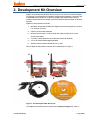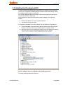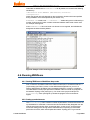
1
ZigBit™ Amp Development Kit 2.0
User’s Guide
Doc. S-ZDK-451~02 v.2.0
March 2008
© 2008 MeshNetics
ZIGBIT™ AMP DEVELOPMENT KIT 2.0
USER’S GUIDE
© 2008 MeshNetics. All rights reserved.
No part of the contents of this manual may be transmitted or reproduced in any form or by any means without the
written permission of MeshNetics.
Disclaimer
MeshNetics believes that all information is correct and accurate at the time of issue. MeshNetics reserves the right
to make changes to this product without prior notice. Please visit MeshNetics website for the latest available
version.
MeshNetics does not assume any responsibility for the use of the described product or convey any license under
its patent rights.
MeshNetics warrants performance of its hardware products to the specifications applicable at the time of sale in
accordance with MeshNetics standard warranty. Testing and other quality control techniques are used to the
extent MeshNetics deems necessary to support this warranty. Except where mandated by government
requirements, testing of all parameters of each product is not necessarily performed.
Trademarks
MeshNetics®, ZigBit, BitCloud, SensiLink, as well as MeshNetics and ZigBit logos are trademarks of MeshNetics
Ltd.
All other product names, trade names, trademarks, logos or service names are the property of their respective
owners.
Technical Support
Technical support is provided by MeshNetics.
E-mail: [email protected]
Please refer to Support Terms and Conditions for full details.
Contact Information
MeshNetics
EMEA Office
Am Brauhaus 12
01099, Dresden, Germany
Tel: +49 351 8134 228
Office hours: 8:00am - 5:00pm (Central European Time)
Fax: +49 351 8134 200
US Office
5110 N. 44th St., Suite L200
Phoenix, AZ 85018 USA
Tel: (602) 343-8244
Office hours: 9:00am - 6:00pm (Mountain Standard Time)
Fax: (602) 343-8245
Russia Office
9 Dmitrovskoye Shosse, Moscow 127434, Russia
Tel: +7 (495) 725 8125
Office hours: 8:00am - 5:00pm (Central European Time)
Fax: +7 (495) 725 8116
E-mail: [email protected]
www.meshnetics.com
© 2008 MeshNetics
Page 2/54
ZIGBIT™ AMP DEVELOPMENT KIT 2.0
USER’S GUIDE
Table of Contents
1.
Introduction...................................................... 6
2.
Development Kit Overview.......................... 10
5.
SerialNet..........................................................40
2.1.
Hardware General Specifications ........................... 12
6.
Serial Bootloader...........................................41
2.2.
MeshBean Amp Featured Components................. 13
7.
Programming with BitCloud API.................42
2.2.1. ZigBit Amp Module...................................... 13
7.1.
API Overview............................................................42
2.2.2. Sensors........................................................ 13
7.2.
Using AVR Programming Tools ..............................42
2.2.3. USB to UART Bridge .................................. 13
7.3.
How to Build Minimum Application ..........................43
2.2.4. Silicon Serial for UID storage...................... 13
7.4.
Sample Applications.................................................43
MeshBean Amp Board Design ............................... 14
8.
Troubleshooting ............................................45
2.3.1. Connectors and Jumpers............................ 16
Appendices................................................................47
2.3.
4.6.5. Visualization of the Sensor Data .................39
2.3.2. Buttons, Switches and LEDs ...................... 19
2.3.3. External Antenna......................................... 20
2.4.
BitCloud Software.................................................... 20
3.
Getting Started .............................................. 23
3.1.
Overview .................................................................. 23
3.2.
System Requirements............................................. 23
3.3.
Installing the Development Kit................................. 24
3.4.
Connecting the Board to PC ................................... 25
3.5.
Powering the Boards ............................................... 26
3.6.
Testing WSN Functionality Using SerialNet ........... 26
3.7.
Testing the Board Controls and Sensors................ 27
3.8.
Measuring Power Consumption.............................. 28
3.9.
Antenna Precautions ............................................... 28
4.
ZBNDemo Application ................................. 29
4.1.
Overview .................................................................. 29
4.2.
Programming the Boards ........................................ 30
4.2.1. Using Serial Bootloader .............................. 31
4.2.2. Using JTAG ................................................. 31
4.3.
Using the Boards ..................................................... 32
4.4.
Sensors Data and Battery Level Indication............. 34
4.5.
WSN Monitor ........................................................... 35
4.6.
Running ZBNDemo ................................................. 36
4.6.1. Starting ZBNDemo on MeshBean Amp
nodes ........................................................... 36
4.6.2. Setting up node timeouts ............................ 36
4.6.3. Node Reset.................................................. 37
4.6.4. Changing Frequency Channels.................. 37
© 2008 MeshNetics
Page 3/54
ZIGBIT™ AMP DEVELOPMENT KIT 2.0
USER’S GUIDE
List of Figures
Figure 1. The Development Kit delivery set ........................ 10
Figure 2. MeshBean Amp with integrated UID Silicon
Serial, assembled with external antenna ............ 15
Figure 3. MeshBean Amp functional diagram..................... 16
Figure 4. BitCloud Block Diagram ....................................... 21
Figure 5. COM port drivers in the Windows Device
Manager window.................................................. 24
Figure 6. Hyper Terminal Hardware Test report ................. 27
Figure 7. WSN Monitor GUI................................................. 35
Figure 8. Example of file containing the node titles............. 36
Figure 9. WSN Monitor Tools/Settings menu ..................... 37
Figure 10. Resetting the node ............................................. 37
Figure 11. Setting channel mask dialog box ....................... 38
Figure 12. Setting the channel mask using checkboxes .... 38
Figure 13. AVR Studio dialog box for firmware upload using
JTAG .................................................................... 49
© 2008 MeshNetics
Page 4/54
ZIGBIT™ AMP DEVELOPMENT KIT 2.0
USER’S GUIDE
List of Tables
Table 1. The ZDK Amp support packages.......................... 11
Table 2. MeshBean Amp Board Specifications .................. 12
Table 3. Expansion slot pinout............................................. 16
Table 4. JTAG connector pinout.......................................... 18
Table 5. J1 jumper settings: current measurement........... 19
Table 6. J2 jumper settings: MeshBean Amp power
source................................................................... 19
Table 7. J3 jumper settings: Serial/USB selection ............ 19
Table 8. Serial interface pinout ............................................ 19
Table 9. External antenna set.............................................. 20
Table 10. System requirements........................................... 23
Table 11. COM-port settings for hardware testing.............. 26
Table 12. DIP switch configurations used in ZBNDemo..... 33
Table 13. LED indication used in ZBNDemo ...................... 33
Table 14. Typical problems and solutions........................... 45
Table 15. The ZDK Amp file structure................................. 47
© 2008 MeshNetics
Page 5/54
ZIGBIT™ AMP DEVELOPMENT KIT 2.0
USER’S GUIDE
1. Introduction
Intended Audience and Purpose
This document is intended for engineers and software developers working with the
ZigBit™ Amp Development Kit (ZDK Amp) designed for WSN extended-range high-output
applications. The Kit is used to evaluate the performance and the features of ZigBit Amp
modules and the BitCloud software, and to implement custom applications on top of
BitCloud API.
Safety and Precautions
The product contains electronics, which are electrically sensitive. Please take necessary
precautions when using such devices. MeshNetics does its best to protect the product
components from electrostatic discharge phenomena, but we encourage our users to
follow common guidelines to avoid electrostatics by using proper grounding etc.
Any modifications of the hardware, its components or improper use of the product can
cause an uncontrolled violation of the in-band or out-band radiation levels. It can result in
progressing violation of emission level limits, thus causing harmful interference.
Precautions
The product radiates power in the microwave band with power level of less than 100 mW,
which complies with the FCC rules (Part 15). In order to prevent the undesirable influence
of electromagnetic field on operating personnel the recommended distance between an
operator and antenna should not be allowed less than 20 centimeters. When the parts of
the product are turned on, an operator should avoid touching the PCB antenna and the
board itself.
AC/DC adapters which can be used with the product contain high voltage circuits. General
precautions should be taken against electric shock before the product hardware is mains
powered.
The ZigBit Amp Development Kit contains fragile components. Please handle with care.
Related documents
[1]
ZigBit™ Amp OEM Modules. Product Datasheet. MeshNetics Doc. M-251~03
[2]
BitCloud™ IEEE802.15.4/ZigBee Software. Product Datasheet.
MeshNetics Doc. M-252~08
[3]
eZeeNet™ Software 1.7. SerialNet. Reference Manual. AT-Command Set.
MeshNetics Doc. P-EZN-452~01
[4]
BitCloud™ Software 1.0. BitCloud Stack Documentation.
MeshNetics Doc. P-ZBN-452~02
[5]
BitCloud Developer's Guide. MeshNetics Doc. P-ZBN-452~01
[6]
ZigBit™ OEM Module. Application Note. ZigBit Power Consumption Testing.
MeshNetics Doc. AN-481~01
[7]
BitCloud™ Software 1.0. Serial Bootloader User’s Guide.
MeshNetics Doc. P-ZBN-451~02
[8]
ZigBit™ OEM Module. Application Note. Using ZigBit Module with Analog Sensors.
MeshNetics Doc. AN-481~06
© 2008 MeshNetics
Page 6/54
ZIGBIT™ AMP DEVELOPMENT KIT 2.0
[9]
USER’S GUIDE
BitCloud™ Software 1.0. Range Measurement Application. User’s Manual.
MeshNetics Doc. P-ZBN-451~01
[10]
ZigBee Specification. ZigBee Document 053474r17, October 19, 2007
[11]
Serial asynchronous automatic dialing and control. ITU-T Recommendation V.250,
05/99
[12]
IEEE Std 802.15.4-2003 IEEE Standard for Information technology – Part 15.4
Wireless Medium Access Control (MAC) and Physical Layer (PHY) Specifications
for Low-Rate Wireless Personal Area Networks (LR-WPANs)
[13]
TSL2550 Ambient Light Sensor with Smbus Interface. TAOS Datasheet
TAOS029E. February 2006
http://www.taosinc.com/images/product/document/tsl2550-e67.pdf
[14]
LM73 2.7V, SOT-23, 11-to-14 Bit Digital Temperature Sensor with 2-Wire Interface.
National Semiconductor Corporation Datasheet DS201478. July 2006
http://www.national.com/pf/LM/LM73.html#Datasheet
[15]
CP2102, Single-Chip USB to UART Bridge, Rev. 1.1 9/05. www.silabs.com
[16]
AVR Studio. User Guide. Available in HTML Help with the product.
[17]
JTAGICE mkII Quick Start Guide.
http://www.atmel.com/dyn/resources/prod_documents/doc2562.pdf
[18]
avr-libc Reference Manual 1.4.3
[19]
WinAVR User Manual – 20070525/ By Eric B. Weddington
[20]
Using the GNU Compiler Collection/ By Richard M. Stallman and the GCC
Developer Community
Abbreviations and Acronyms
© 2008 MeshNetics
AC/DC
Alternating Current / Direct Current converter
ADC
Analog-to-Digital Converter
API
Application Programming Interface
Channel Mask
Channel mask is a number that defines the set of working channels
Coordinator
Within ZigBee networks, the ZigBee coordinator is responsible for
starting the network and for choosing certain key network
parameters. The network may be extended through the use of
ZigBee router.
DIP
Dual In-line Package
EEPROM
Electrically Erasable Programmable Read-Only Memory
End device
In ZigBee networks, the ZigBee end device provides sensor data
sent to a router. End device is often subject to power management
restrictions, so it may be in sleeping mode most of the time.
ESD
Electrostatic Discharge
GPIO
General Purpose Input/Output
GUI
Graphical User Interface
HAL
Hardware Abstraction Layer
Page 7/54
ZIGBIT™ AMP DEVELOPMENT KIT 2.0
© 2008 MeshNetics
USER’S GUIDE
I2C
Inter-Integrated Circuit
IDE
Integrated Development Environment
IEEE
Institute of Electrical and Electronics Engineers
IRQ
Interrupt Request
JTAG
Digital interface for debugging of embedded devices, also known as
IEEE 1149.1 standard interface
LED
Light Emitting Diode
LQI
Link Quality Indicator
MAC
Medium Access Control layer
MCU
Microcontroller Unit. In this document, it also means the processor,
which is the core of ZigBit Amp module
MIPS
Million Instructions per Second
NWK
Network layer
OEM
Original Equipment Manufacturer
OTA
Over-The-Air upgrade
PAN ID
Personal Area Network Identifier. In ZigBee, it is 16-bit number which
must be unique for each one of multiple networks working on the
same frequency channel
PCB
Printed Circuit Board
PHY
Physical layer
RAM
Random Access Memory
RF
Radio Frequency
RISC
Reduced Instruction Set Computing microprocessor
Router
In ZigBee networks, routers transfer data and control messages
through the network using a hierarchical routing strategy. The ZigBee
coordinator is also responsible for routing.
RP-SMA
Reversed Polarity Surface Mount Assembly
RS-232
Serial binary data interconnection interface, which is commonly used
in computer serial ports (COM ports)
RSSI
Received Signal Strength Indicator
RTS/CTS
Request to Send / Clear to Send
RX
Receiver
SMA
Surface Mount Assembly
SPI
Serial Peripheral Interface bus
TTM
Time To Market
TX
Transmitter
UART
Universal Asynchronous Receiver/Transmitter
UID
Unique Identifier
Page 8/54
ZIGBIT™ AMP DEVELOPMENT KIT 2.0
USART
Universal Synchronous/Asynchronous Receiver/Transmitter
USB
Universal Serial Bus
VCP
Virtual Com Port
WSN
Wireless Sensor Network
ZDK
ZigBit Development Kit
ZigBee,
Wireless networking standards targeted at low-power sensor
applications [10]
ZigBee PRO
802.15.4
© 2008 MeshNetics
USER’S GUIDE
The IEEE 802.15.4-2003 standard applicable to low-rate wireless
Personal Area Networks [12]
Page 9/54
ZIGBIT™ AMP DEVELOPMENT KIT 2.0
USER’S GUIDE
2. Development Kit Overview
ZigBit™ Amp Development Kit (ZDK Amp) is a simple, out-of-the-box solution designed
for prototyping and development of Wireless Sensor Networks (WSNs). It provides a pair
of MeshBean Amp boards each containing the ZigBit Amp OEM module to test the
wireless network features and develop customized wireless solutions based on BitCloud
Software.
ZigBit Amp Development Kit includes:
1.
MeshBean Amp board (doubled) with ZigBit Amp module equipped by the built-in
U.FL antenna connector
2.
USB 2.0 A/mini-B cable (doubled)
3.
External interface cable – a ribbon cable with single-side IDC-20 pin socket
connector (doubled)
4.
2.4 GHz 3.2 dBi Pulse W1037 Omni-directional antenna (doubled)
5.
U.FL to RP-SMA bulkhead pigtail (doubled)
6.
Software & Documentation Distribution CD (1 disk).
See the ZigBit Amp Development Kit with the numbered parts in Figure 1.
4
4
3
3
1
1
5
5
2
6
Figure 1. The Development Kit delivery set
The ZigBit Amp Development Kit is offered with 2 support packages (see Table 1):
© 2008 MeshNetics
Page 10/54
ZIGBIT™ AMP DEVELOPMENT KIT 2.0
•
•
USER’S GUIDE
ZigBit Amp Development Kit Lite offers access to standard evaluation and
development tools and comes with 45 days of complimentary support. This option
is good for product demonstration, platform evaluation and quick application
prototyping.
ZigBit Amp Development Kit Complete comes with 1 year of professional
support which provides users with continuous software updates, dedicated designin support, and RF design assistance. It's ideal for customers engaged in a full
cycle of developing, prototyping, and launching innovative products made possible
by MeshNetics ZigBit wireless platform. It also features early software release
access, and additional sample applications, including sources for ZBNDemo
application, examples of API use, and more.
Table 1. The ZDK Amp support packages
ZDK Amp Edition
Lite
Complete
ZDK-A1281-PN-LTE
(MNZB-DKL-A24)
ZDK-A1281-PN-CPT
(MNZB-DKC-A24)
Support Duration
45 days
1 year
Hardware design
support
+
+
RF design support
+
+
Software development
support
+
+
Early software
release1 access
Access to Gerber
Files2
Access to bootloader
source code3
Additional sample
applications4
–
+
–
+
–
+
–
+
Response time
72 h, workdays
72 h, workdays
Support channel
E-mail
E-mail
Part Number
1
Early software release access covers technology previews and demos, preliminary datasheets, and advance product
announcement.
2
MeshBean Gerber files greatly expedite custom PCB design-in and accelerate TTM for customer's specific products
based on ZigBit modules and peripherals used within MeshBean development platform such as USB extension, sensor
adaptations and others.
3
Access to serial bootloader source code is essential in building custom tools for serial and OTA upgrades.
4
Additional sample applications include sources for (1) the embedded portion of ZBNDemo, featuring the most
comprehensive example of a typical data acquisition scenario, (2) smaller examples of API use, which may be used as
application "building blocks", (3) sample applications featuring integration of ZigBit w/ 3-rd party sensors.
© 2008 MeshNetics
Page 11/54
ZIGBIT™ AMP DEVELOPMENT KIT 2.0
USER’S GUIDE
2.1. Hardware General Specifications
MeshBean Amp board is intended to evaluate the operation performance of ZigBit Amp
OEM module. ZigBit Amp module with the embedded BitCloud Software provides wireless
connectivity for MeshBean Amp board being a node in a ZigBee network.
The MeshBean Amp board can be configured to operate as a network coordinator, a
router or an end device, by means of setting DIP switches (see Section 2.3.2) and/or
sending AT-commands. The node’s role is defined by the embedded applications.
The boards are delivered with ZigBit Amp preprogrammed with Serial Bootloader and
SerialNet application firmware. For full list of demo applications see Section 2.4.
Gerber file for MeshBean Amp board is available with Complete Support Package only.
The MeshBean Amp basic parameters are presented in Table 2.
Table 2. MeshBean Amp Board Specifications
Parameter
Value
RF
Compliance
2.4 GHz IEEE 802.15.4-2003 [12]
Operating Band
2400–2483.5 MHz
TX Output Power
from 0 dBm to +20 dBm
RX Sensitivity
-101 dBm
RF Transceiver
AT86RF230
Antenna
2.4 GHz 3.2 dBi Pulse W1037 Omni-directional antenna
MCU
Microcontroller
ATmega1281V
RAM
8K Bytes
Flash Memory
128K Bytes
EEPROM
4K Bytes
Performance
Up to 4 MIPS throughput at 4 MHz Clock
Power
Power Supply
Dual AA battery, automatically switched to USB or
AC/DC adapter
Over-Voltage Protection
Yes
Reverse Polarity Protection
Yes
Operating Voltage Range
3.0...3.6 V
Voltage Supervisor
Yes
Miscellaneous
© 2008 MeshNetics
Sensors
Digital: Ambient Light/ Ambient Air Temperature
LED Indicators
3 programmable color status LEDs
Switches
3 DIP switches
Page 12/54
ZIGBIT™ AMP DEVELOPMENT KIT 2.0
USER’S GUIDE
Parameter
Value
Buttons
2 programmable buttons
Size
60 x 76 x 39 mm
Operating Temperature Range
– 40°C to + 85°C. Minor degradation of clock stability
may occur beyond the –20°C to +70°C range.
2.2. MeshBean Amp Featured Components
2.2.1. ZigBit Amp Module
Each of MeshBean Amp boards includes the ZigBit Amp module installed. The ZigBit Amp
module is an ultra-compact, low-power, extended range, high sensitivity 2.4GHz
802.15.4/ZigBee OEM module from MeshNetics. ZigBit Amp module is based on Atmel’s
Z-Link 2.4GHz platform. It includes ATmega1281V Microcontroller and AT86RF230 RF
Transceiver.
ZDK Amp module features the U.FL antenna connector allowing for the use of external
RP-SMA antenna which can be attached through the bulkhead pigtail supplied within the
Development Kit.
Detailed specifications of the ZigBit Amp, including the module interfaces, voltage levels,
power consumption, are available in the datasheet [1].
2.2.2. Sensors
The board incorporates light sensor TSL2550T from TAOS and temperature sensor
LM73CIMK from National Semiconductors. Both sensors are connected in parallel to the
I2C bus. For more information on the sensors see their datasheets [13], [14] available from
the corresponding manufacturers’ websites.
NOTE:
In addition to the built-in, onboard sensors, external sensors selected by developer can be
used. An external sensor can be connected to the terminals of External interface cable
leading to the onboard Expansion slot. See the corresponding pinout in Table 2. As an
example, connection of an external sensor is illustrated in Application Note [8].
2.2.3. USB to UART Bridge
CP2102, the USB to UART Bridge controller from Silicon Labs [15], is installed on the
board. It provides seamless USB interface to any RS-232 legacy device. If the controller’s
driver has been installed on PC during the deployment of the whole Development Kit (see
Section 3.3) the onboard USB port is visible on the PC as generic COM port with a
particular number.
2.2.4. Silicon Serial for UID storage
UID (Unique Identifier) is HEX value, 8 bytes long. UID is used for setting unique MAC
address of the node.
UID is hardware defined value. It is programmed into a chip (Silicon Serial Number
DS2411R+ by Maxim/Dallas) at the factory.
UID is unique, and cannot be overwritten. In order to ensure the presence of UID on the
board it is required to execute Hardware Test application (see Section 3.7 for details).
© 2008 MeshNetics
Page 13/54
ZIGBIT™ AMP DEVELOPMENT KIT 2.0
USER’S GUIDE
2.3. MeshBean Amp Board Design
The MeshBean Amp board contains the ZigBit Amp module, which operates as
ZigBee/802.15.4 transceiver. It also includes sensors, buttons, DIP switches, and a set of
interfaces.
The board provides the following interfaces:
•
•
•
•
•
•
•
•
•
•
•
•
USB 2.0 port
Light and temperature sensors
2 push buttons controlling the software
Reset button
3 DIP switches
3 software-controlled LEDs
JTAG connector for software upload and debugging
Power connector (3 V) to attach an AC/DC adapter (which is not supplied with ZDK
Amp)
20-pin Expansion slot containing external ZigBit Amp’s interfaces (see Table 3),
including:
o
Serial port interface (RS-232)
o
USART
o
Buffered I2C interface with ESD protection and voltage level translation
o
ADC/GPIO
Battery compartment for AA-size batteries
3 configuration jumpers
3 clamps for power consumption measurements.
Also, the board contains an internal voltage regulator to supply most of the components
with 3.6 V.
See Figure 2 for the layout of MeshBean Amp board adjusted to fit to the ZigBit Amp
module. See also Figure 3 for the board’s functional diagram.
© 2008 MeshNetics
Page 14/54
ZIGBIT™ AMP DEVELOPMENT KIT 2.0
USER’S GUIDE
Figure 2. MeshBean Amp with integrated UID Silicon Serial, assembled with
external antenna
© 2008 MeshNetics
Page 15/54
ZIGBIT™ AMP DEVELOPMENT KIT 2.0
USER’S GUIDE
Figure 3. MeshBean Amp functional diagram
2.3.1. Connectors and Jumpers
The board connector pinouts and jumper settings are presented in Table 3 through
Table 8.
IMPORTANT NOTE:
All manipulations with connectors or jumpers should be done when the board is not
powered!
Table 3. Expansion slot pinout
© 2008 MeshNetics
Pin
Name
I/O
Description
1
UART_RTS
Input
Request to Send Pin. RS-232 level.
Page 16/54
ZIGBIT™ AMP DEVELOPMENT KIT 2.0
© 2008 MeshNetics
USER’S GUIDE
Pin
Name
I/O
Description
2
UART_TXD
Input
Transmit Data Pin (meaning that the host
device will transmit data to this line). RS-232
level.
3
UART_CTS
Output
Clear To Send signal from the module.
Active low. RS-232 level.
4
UART_RXD
Output
Receive Data Pin (meaning that the host
device will receive data from this line). RS-232
level.
5
GND
Digital/analog ground
6
GND
Digital/analog ground
7
I2C_CLK
Input
I2C clock. It is connected to the I2C_CLK pin
of the module via low-voltage level translators.
For details, refer to ZigBit Amp datasheet [1].
8
I2C_DATA
Bidirectional
I2C data. It is connected to the I2C_DATA pin
of the module via low-voltage level translators.
For details, refer to ZigBit Amp datasheet [1].
9
+3.6V
Output
Output of internal voltage regulator. Normally,
the voltage is 3.6 V.
10
V_XX
Output
ZigBit Amp supply voltage
11
RESET
Input
Reset Pin. Active low. This pin is connected in
parallel to the RESET button on the board.
12
USART_TXD
Output
This is Transmit Data Pin for USART0
interface of the ZigBit Amp module. It is
connected directly to the USART0_TXD pin of
the module. Digital logic level. For details, refer
to ZigBit Amp datasheet [1].
13
USART_RXD
Input
This is Receive Data Pin for USART0
interface of the ZigBit Amp module. It is
connected directly to the USART0_RXD pin of
the module. Digital logic level. For details, refer
to ZigBit Amp datasheet [1].
14
USART_CLK
Input
This is Clock Data Pin for USART0 interface
of the ZigBit Amp module. It is connected
directly to the USART0_EXTCLK pin of the
module. Digital logic level. For details, refer to
ZigBit Amp datasheet [1].
15
GND
16
ADC_INPUT1
Input
ADC input. This pin is connected directly to the
ADC_INPUT_1 pin of the module. For details,
refer to ZigBit Amp datasheet [1].
17
ADC_INPUT2
Input
ADC input. This pin is connected directly to the
ADC_INPUT_2 pin of the module. For details,
refer to ZigBit Amp datasheet [1].
18
ADC_INPUT3
Input
ADC input. This pin is connected directly to the
ADC_INPUT_3 pin of the module. For details,
refer to ZigBit Amp datasheet [1].
Digital/analog ground
Page 17/54
ZIGBIT™ AMP DEVELOPMENT KIT 2.0
Pin
Name
I/O
19
GND
Digital/analog ground
20
GND
Digital/analog ground
USER’S GUIDE
Description
GENERAL NOTES:
Pins 12, 13, 14, 16, 17, 18 are not buffered and driven by the MCU pins directly. Thus this
interface should be used with precautions at the low supply voltages to avoid damaging
the module.
Pins 7 and 8 are connected via voltage level translators with ESD protection. Thus these
pins can be used easily to connect extra I2C sensors without extra logic.
Voltage on the V_XX pin does not depend on the state of jumper J1 or ammeter
connection between clamps CM+, CM–.
Table 4. JTAG connector pinout
Pin
Name
Description
1
JTAG_TCK
Scan clock
2
JTAG_GND
Digital ground
3
JTAG_TDO
Test data output
4
JTAG_VCC
Controller supply voltage
5
JTAG_TMS
Test mode select
6
JTAG_RST
Reset controller; active low
7
N_Cont
Not connected
8
N_Cont
Not connected
9
JTAG_TDI
Test data input
10
JTAG_GND
Digital ground
NOTE:
JTAG connector pinout is compatible with ATmega JTAGICE mkII in-circuit emulator
connector.
© 2008 MeshNetics
Page 18/54
ZIGBIT™ AMP DEVELOPMENT KIT 2.0
USER’S GUIDE
Table 5. J1 jumper settings: current measurement
Jumper position
Description
J1 is mounted
This position is to be set for normal operation.
J1 is open
In this position, the ZigBit Amp module is
unpowered while remaining parts of the board are
powered. This position is used to measure current
consumption of the ZigBit Amp module (see
Section 3.8).
Table 6. J2 jumper settings: MeshBean Amp power source
Jumper position
Description
J2 bridges pin “2” and pin “3”
MeshBean Amp is to be powered by USB.
J2 bridges pin “2” and pin “1”
MeshBean Amp is to be powered by external DC
source or by batteries in case external DC is
disconnected.
Table 7. J3 jumper settings: Serial/USB selection
Jumper position
Description
J3 bridges central pin and RS-232
pin
The board will use serial port (available in the
Expansion slot) for connection to the host
J3 bridges central pin and USB pin
The board will use USB for connection to the host
IMPORTANT NOTES:
Any other position of jumpers J2 and J3 or their omission may cause permanent
damage of the hardware.
Powering the board without J1 jumper and ammeter connection between clamps CM+ and
CM- may cause a permanent damage of the hardware.
When making connection to the PC’s serial port through the Expansion slot consider the
pinout as indicated below in Table 8.
Table 8. Serial interface pinout
Signal
Expansion slot pins
Serial port pins
(PC side)
RXD
4: UART_RXD
2
TXD
2: UART_TXD
3
CTS
3: UART_CTS
8
RTS
1: UART_RTS
7
GND
5, 6, 15, 19, 20: GND
5
2.3.2. Buttons, Switches and LEDs
The board includes the Power switch, 3 DIP switches, 2 buttons, one Reset button that
generates hardware reset signal, 3 software-defined LEDs (green, yellow and red). Any of
© 2008 MeshNetics
Page 19/54
ZIGBIT™ AMP DEVELOPMENT KIT 2.0
USER’S GUIDE
onboard buttons, DIP switches and LEDs can be controlled with the application running on
the ZigBit Amp.
DIP switches are useful to control the board’s internal parameters. For instance, TX output
power can be set for Range Measurement Application [9]. DIP switches can be tested
when running the Hardware Test application (see Section 3.6).
2.3.3. External Antenna
Each of the on-board ZigBit Amp modules mounted on MeshBean Amp is equipped with
the built-in U.FL antenna connector. On the other hand, MeshBean Amp has the on-board
connector to attach the external RP-SMA antenna. The specifications are presented
below in Table 9 for external antenna set supplied with the Development Kit.
Table 9. External antenna set
Part Number
Description
Size
W1037
2.4 GHz 3.2 dBi Pulse Omni-directional
antenna
L 6.65 in
PT-SMA-RP
I-PEX U.FL to RP-SMA Bulkhead
Pigtail
L 6 in X D 1.13 mm cable
IMPORTANT NOTE:
Only the RP SMA Connector antennas can be used for a custom design!
Make sure that the supplied U.FL to RP-SMA Bulkhead Pigtail is linking tightly the onboard antenna connector and the U.FL antenna connector before using a board. Attach
the SMA antenna to the on-board connector, matching the antenna’s female coaxial
thread with the connector’s male thread.
2.4. BitCloud Software
BitCloud is a full-featured, next generation embedded software stack from MeshNetics.
The stack provides a software development platform for reliable, scalable, and secure
wireless applications running on MeshNetics ZigBit modules. BitCloud is designed to
support a broad ecosystem of user-designed applications addressing diverse
requirements and enabling a full spectrum of software customization.
BitCloud is fully compliant with ZigBee PRO and ZigBee standards for wireless sensing
and control. It provides an augmented set of APIs which, while maintaining 100%
compliance with the standard, offer extended functionality designed with developer's
convenience and ease-of-use in mind.
The topmost of the core stack layers, APS, provides the highest level of networkingrelated APIs visible to the application. ZDO provides a set of fully compliant ZigBee Device
Object APIs which enable main network management functionality (start, reset, formation,
join). ZDO also defines ZigBee Device Profile types, device and service discovery
commands implemented by the stack.
ZDK Amp provides everything a developer would need to develop custom applications
using BitCloud API [4]. The general guidelines to BitCloud programming are given in [5].
API-based demos are provided in source code which can be modified and extended. In
the ZigBit Amp Development Kit, using the API makes it possible to develop WSN
applications for a variety of networking scenarios. For example, an end device can be
configured to communicate with a router between the periods of sleep thus saving power.
Another configuration of BitCloud Software, SerialNet, enables a user to implement
customized WSN scenarios without developing any WSN application code. In this case
WSN nodes are controlled through AT-commands (see Section 5).
© 2008 MeshNetics
Page 20/54
ZIGBIT™ AMP DEVELOPMENT KIT 2.0
USER’S GUIDE
The structure of BitCloud Software is presented in Figure 4. It is detailed in datasheet [2].
Figure 4. BitCloud Block Diagram
The Development Kit includes two kinds of applications (see Appendix A). Evaluation tools
are delivered in binary format. Sample applications are available in source code.
The following evaluation tools are delivered:
•
•
•
•
•
SerialNet application lets the AT-commands be interpreted locally or forwarded for
execution on remote nodes.
Hardware Test (see Section 3.7) is a simple application which tests major
MeshBean2 board components for correct operation.
Range Measurement Tool is an application intended to measure radio
performance of ZigBit-based devices and/or to make comparison with platforms of
other manufacturers. Usage essential information and guiding instructions are
given in [9].
ZBNDemo with WSN Monitor
Serial Bootloader is a software utility designed to program an application code into
WSN nodes through USB or serial port, without using JTAG. See the description of
Serial Bootloader in Section 6.
The following sample applications are delivered with source code (referenced as given in
brackets):
•
•
•
•
•
•
ZBNDemo (ZBNDemo)
Low Power Networking (Lowpower)
Ping-Pong (Pingpong)
Peer-To-Peer Data Exchange (Peer2peer)
Blink minimal sample application (Blink)
Hardware Test (HardwareTest).
The ZBNDemo application is a featured ZDK Amp application demonstrating the WSN
performance. It is presented in details in Section 4. The source code for ZBNDemo is
available with Complete Support Package only.
© 2008 MeshNetics
Page 21/54
ZIGBIT™ AMP DEVELOPMENT KIT 2.0
USER’S GUIDE
The rest of programs are sample implementations triggering common BitCloud APIs. Blink
is a minimal application (see Section 7.3). Low Power, Ping-Pong, and Peer-To-Peer
applications are introduced in Section 7.4.
© 2008 MeshNetics
Page 22/54
ZIGBIT™ AMP DEVELOPMENT KIT 2.0
USER’S GUIDE
3. Getting Started
3.1. Overview
This section describes the system requirements and ZDK Amp deployment. It also
provides how-to instructions on handling the boards, testing WSN functionality and
performing local hardware tests.
3.2. System Requirements
Before using the Kit, please ensure that the following system requirements are met (see
Table 10).
Table 10. System requirements
Parameter
Value
Note
PC
CPU
Intel Pentium III or higher,
800 MHz
RAM
128 MB
Hard disk free space
50 MB
JTAG emulator
JTAGICE mkII emulator
with cable
Necessary to upload and debug
firmware onto the MeshBean
Amp board through JTAG (see
Appendix B).
Software
Operating system
Windows2000/XP
USB driver
CP210x USB to UART
Bridge VCP Driver
Necessary to connect MeshBean
Amp to PC via USB port (see
Section 3.4)
IDE
AVR Studio 4.13 +
Service Pack 1 +
WinAVR
Necessary to upload firmware
image through JTAG (see
Appendix B), and to develop
applications using API (see
Section 7)
Serial Bootloader utility
Java virtual machine
© 2008 MeshNetics
Necessary to upload firmware
image without using JTAG (see
Section 6)
Java Runtime
Environment (JRE) 5
Update 8, or more recent
Necessary to run the WSN
Monitor application (see Section
4.5
Page 23/54
ZIGBIT™ AMP DEVELOPMENT KIT 2.0
USER’S GUIDE
3.3. Installing the Development Kit
In order to install the Development Kit, insert the ZDK Amp Software and Documentation
CD into your PC CDROM. The ZDK installation wizard should start automatically. Specify
the installation path and follow the instructions.
As a result the ZDK Amp file structure under the selected path will be generated on the
PC, which is described in Appendix A.
During the ZDK Amp deployment the following auxiliary software can be optionally
installed:
•
•
USB to UART Bridge VCP driver for Windows platform
Java Runtime Environment (JRE).
To complete the installation of VCP driver before use of the ZDK Amp do the following:
•
•
Connect MeshBean Amp board to the USB port. Windows should detect the new
hardware. Follow the instructions provided by the driver installation wizard.
Make sure that the driver is installed successfully and the new COM port is present
in the device list. Open the Device Manager window shown in Figure 5:
Start/Control Panel/System/Hardware/Device Manager.
Figure 5. COM port drivers in the Windows Device Manager window
To resolve possible problems see Section 3.4.
© 2008 MeshNetics
Page 24/54
ZIGBIT™ AMP DEVELOPMENT KIT 2.0
USER’S GUIDE
NOTE:
USB to UART Bridge VCP driver for Windows platform is also available from the
manufacturer’s site:
http://www.silabs.com/tgwWebApp/public/web_content/products/Microcontrollers/USB/en/
mcu_vcp.htm.
Java Runtime Environment (JRE) is also available from
http://java.sun.com/javase/downloads/index.jsp.
There may be other Java instances already installed on your computer before the use of
ZDK Amp. To avoid confusion, edit start.bat file in ./Evaluation Tools/ZBNDemo
(WSN Monitor) subdirectory containing the WSN Monitor. Make sure to provide full
path to the Java executable file, specify its file name extension (.exe) explicitly.
Current version of the AVR Studio [16] with Service Pack can be freely downloaded from
the Atmel’s website (http://www.atmel.com). Simply launch the downloaded installer
programs and follow the setup instructions.
The WinAVR suite of development tools can be downloaded from
http://sourceforge.net/projects/winavr. To install WinAVR follow the setup instructions.
3.4. Connecting the Board to PC
The board can be connected to host PC via USB port, using USB 2.0 A/mini-B cable
supplied within the Kit. USB is typical connection. Furthermore, it provides the convenient
possibility to link multiple boards to a single PC. Besides, no battery is required once a
board is powered via USB.
Because wireless applications usually employ host connection through COM port, linking
the onboard USB to UART Bridge controller to PC requires installation of the USB to
UART Bridge VCP driver (see details in Section 3.3, Section 2.2.3). As a result, generic
COM port can be used to access a board via USB.
IMPORTANT NOTES:
When USB connection is used, the COM port number would be changed by the Windows
operating system if the board has been reconnected. To avoid confusion use Windows
Control Panel to check on the actual port number.
Under some circumstances, the boards can conflict with other USB devices recently
installed. In such cases, the Windows Device Manager would show a problem occurred
during the plug-and-play procedure or it would not detect the USB to UART Bridge
controller at all. Possible solution is to change the USB ID for the board, using special
utility available from the controller’s manufacturer. See Section 8 for details.
Alternatively, the board can be connected to host PC via serial port, using a serial cable
(not provided with ZDK Amp). Serial port pinout is presented in Table 8.
IMPORTANT NOTE:
USB and serial port (RS-232) share the same physical port on the board. They cannot be
used at the same time.
Keep in mind that the connection mode is controlled by setting of jumper J3 (see Table 7).
© 2008 MeshNetics
Page 25/54
ZIGBIT™ AMP DEVELOPMENT KIT 2.0
USER’S GUIDE
3.5. Powering the Boards
The MeshBean Amp boards can be powered by a pair of AA-size batteries, via the USB
port or they can be fed via AC/DC adaptor mains powered. First, set J2 jumper to select
MeshBean Amp power source (see Table 6). Turn power ON by means of the on-board
Power switch before using the board.
The nominal voltage is 3.3 V. Using AC/DC adaptor plugged into DC connector
disconnects AA batteries automatically.
To get the board powered via USB the J2 jumper must be set to bridge pin “2” and pin
“3”, as specified in Table 6.
In order to make accurate measurements of sensor parameters, voltage stability is critical.
USB power is not stable enough, which can affect transmission of power level or RF
parameters.
IMPORTANT NOTES:
It is strongly recommended to check up the power supply voltage before programming the
boards by Serial Bootloader or by JTAG. Power drops happened during the programming
process could result in an inoperable state of the ZigBit Amp or its permanent damage.
Using the discharged batteries (when the voltage is below the specified limit) may cause
damage of flash memory or EEPROM as well. If that happened, programming by means
of Serial Bootloader would fail. In this case the only option becoming available would be
using of JTAG emulator (see Appendix B).
Don’t use nickel-cadmium rechargeable batteries, for their double output is unsufficient.
Nevertheless, using alkaline cells is acceptable for short term usage.
3.6. Testing WSN Functionality Using SerialNet
All the boards are delivered preprogrammed with the SerialNet firmware (see Section 5).
Connect the board to PC (see Section 3.4).
Run standard Hyper Terminal utility which is a part of Windows 2000/XP:
Start/All Programs/ Accessories/ Communications/ Hyper Terminal.
Select logical value for COM port provided by the system (see Section 3.4). COM port
parameters should be set to the values given in Table 11.
Table 11. COM-port settings for hardware testing
Option
Value
Data Rate
38 400 bps
Data Bits
8
Parity
None
Stop Bits
1
Flow Control
None, unless data transmission is planned
between the boards, so Hardware flow
control option selected
Type the “AT” command and press Enter key.
The board responds to Hyper Terminal with “OK“.
Now, a user can play various networking scenarios by sending AT commands fully
described in [3].
© 2008 MeshNetics
Page 26/54
ZIGBIT™ AMP DEVELOPMENT KIT 2.0
USER’S GUIDE
A simple networking scenario for building WSN, transmitting data between the WSN
nodes and accessing the nodes’ interfaces is presented in the Examples Section of the
document [3].
3.7. Testing the Board Controls and Sensors
To check the onboard controls and sensors the Hardware Test application can be used.
Connect the board to the PC.
Upload Hardware Test image onto the boards. The Hardware Test image files are listed in
Appendix A.
Run Hyper Terminal utility in the same manner as described above (see Section 3.6).
While the Hardware Test is running, all the board LEDs are blinking. Reports are
generated each second (see Figure 6), and include the status of buttons, DIP switches,
the UID chip number and sensor readings. To test the hardware, you can perform simple
manipulations with the board: press the buttons, move the DIP switches, manually hide
the light sensor from light, finger the temperature sensor and so on. You should see the
changes in parameters reported through Hyper Terminal (see Figure 6).
NOTE:
During the test, if you reconnect the board to USB or replace it with another one, the
operating system may arbitrarily switch this particular USB connection to another COM
port. Apparently, Hyper Terminal does not recognize such changes. If this happens, you
have to reconnect Hyper Terminal to a proper port. Simply select File/New
Connection menu item and repeat the connection procedure.
Figure 6. Hyper Terminal Hardware Test report
© 2008 MeshNetics
Page 27/54
ZIGBIT™ AMP DEVELOPMENT KIT 2.0
USER’S GUIDE
3.8. Measuring Power Consumption
The board allows the measurement of current consumption of the single ZigBit Amp
module. To perform the measurement, connect ammeter to the clamps denoted as CM+
and CM- and remove jumper J1. To exclude power consumption by the interfaces and the
peripherals connected to ZigBit Amp, all interfaces should be disconnected, but the
external antenna should be connected to the board. Refer to the Application Note [6] for
details.
3.9. Antenna Precautions
External antennas were matched and tuned, with taking into account all the onboard
components which would affect antenna performance, including the ZigBit Amp’s shield,
battery compartment and plastic legs. Any other object approached or put closely next to
antenna distorts the antenna pattern.
Do not put the module into enclosure. Do not mount the board on metal surface. Do not
use metal screws over 5 mm long to fasten the board legs. Use plastic screws instead.
Mount plastic legs from bottom side only, next to the battery compartment. Do not use the
legs made of different plastic composite. Omitting these plastic legs would significantly
affect antenna performance as well.
Handle the external antenna with care, to avoid mechanical damage.
© 2008 MeshNetics
Page 28/54
ZIGBIT™ AMP DEVELOPMENT KIT 2.0
USER’S GUIDE
4. ZBNDemo Application
4.1. Overview
The network performance of ZigBit Amp platform is demonstrated with the ZBNDemo
application which is based on the BitCloud software API. This application comprises the
embedded firmware, which supports functions for coordinator, router and end device, and
the GUI part – the WSN Monitor which is run on a PC.
Thanks to the ZBNDemo application, the MeshBean Amp boards are organized into a set
of nodes constituting a wireless network. The LEDs of a board indicate the board current
state and activities. End devices and routers read from the onboard sensors and send the
readings to coordinator in packets. End devices also follow a duty cycle, waking up
occasionally to transmit the sensor data. That data is displayed on WSN Monitor panes as
temperature, light and battery level measurements.
End device is mostly sleeping, waking up shortly each 10 seconds for activities. During the
sleep period, you can force end device for waking up by pressing the SW1 button.
Router sends data each 1 second. Using UART, the coordinator transmits the received
packets, along with its own sensor data, to the GUI application (WSN Monitor).
The WSN Monitor visualizes the network topology in a form of tree. It also displays the
node parameters like node addresses, node sensor information and node link quality data.
Measured in dBm, RSSI indicates link’s current condition. The RSSI resolution is 3 dBm.
LQI is a certain numeric value defined within the 0…255 range to measure the link quality.
Larger values mean better link, while values close to zero indicate poor connection.
In regard to the ZBNDemo, Section 4.3 describes how to use the boards. GUI is described
in Section 4.5. Further instructions are given in Section 4.6.
The application is delivered with source code included (see Appendix A). It is implemented
on top of the BitCloud API and it can be modified as described in Section 7.
With ZBNDemo, the number of routers and/or end devices used is limited only by the
network parameters described in Section 7.4.
© 2008 MeshNetics
Page 29/54
ZIGBIT™ AMP DEVELOPMENT KIT 2.0
USER’S GUIDE
4.2. Programming the Boards
First, ZBNDemo image should be loaded onto the board. The location of ZBNDemo image
files is listed in Appendix A.
ZBNDemo image file can be uploaded into the boards in one of two ways: by means of
Serial Bootloader utility (see Section 4.2.1) or in AVR Studio, using JTAG emulator.
JTAGICE mkII from Atmel [17] 5 (see Section 4.2.2) is recommended.
IMPORTANT NOTE:
Be careful selecting the method of the node programming. Each of MeshBean Amp
boards come with the bootstrap uploaded onto the ZigBit Amp’s MCU, which is needed to
run Serial Bootloader. If JTAG had been used, this would make Serial Bootloader useless
until bootstrap is reloaded to the board.
To be connected with WSN network each node should be identified with a unique MAC
address. If MAC address is not defined by a UID hardware chip, the address of the node
should be programmed manually. Programming a MeshBean Amp board with MAC
address can be performed in four ways.
1.
MAC address can be uploaded to a board by means of Serial Bootloader using a
command line flag (see [7]).
2.
It can be specified in Makefile when defining the compilation for an application (see
details in Section 7.4). The resulting image file containing the unique MAC address
can be uploaded to the board either by JTAG or using Serial Bootloader.
3.
Otherwise, MAC address can be programmed sending SerialNet AT-commands,
as described in [3].
4.
Value stored in UID is used as MAC address.
MAC address is utilized for identification of the node within the network. Default value of
MAC address is zero. The module would not join the network unless MAC address is set
to any non-zero value which is not equal to 0xFFFFFFFFFFFFFFFF.
Notice: Using UID number, you can design the network with “random” MAC addresses as
UID number is a random value.
BitCloud software detects MAC address as follows. At startup, BitCloud Software attempts
to load MAC address from EEPROM. If there is 0 or 0xFFFFFFFFFFFFFFFF value in
EEPROM, BitCloud attempts to load MAC address from UID chip. If there is no UID, the
node will not be able to join the network.
5
Another JTAG programmer may be also used but it should be compatible with the Atmel 1281 MCU.
© 2008 MeshNetics
Page 30/54
ZIGBIT™ AMP DEVELOPMENT KIT 2.0
USER’S GUIDE
4.2.1. Using Serial Bootloader
In order to program the boards by Serial Bootloader perform the following steps:
1.
Connect MeshBean Amp to the PC via USB or serial port, depending on the
position of jumper J3 (see Table 7). Turn power ON by means of the on-board
Power switch.
2.
Run Serial Bootloader. In command line, specify the image file as ZBNDemo.srec
(see Appendix A), the COM port and the optional command line parameters. See
[7] for details.
3.
Press reset button on the board.
4.
Release reset button on the board. Serial Bootloader expects that the button will be
released within approximately 30 seconds. If this would not happen, the booting
process would stop.
NOTE:
If a node has been configured as end device and it is currently controlled by an
application, the node should be powered off before reprogramming.
Make sure that J3 position corresponds to the actual connection of the board, namely
Serial or USB.
Serial Bootloader indicates the operation progress. Once an upload is successfully
completed, the board would restart automatically. If an upload fails, Serial Bootloader
would indicate the reason. In rare cases, booting process would fail due to the
communication failure between the board and the PC. If this happened, attempt booting
again or try using conventional serial port, instead of USB. If booting fails, the program
recently uploaded to the board would be corrupted, but the board could be reprogrammed
again.
4.2.2. Using JTAG
Link JTAG emulator to the MeshBean Amp’s onboard JTAG connector (see Figure 2).
Start uploading process under AVR Studio, following the instructions from [16] and [17].
Select the image file as ZBNDemoApp.hex (see Appendix A) to upload.
Check ON the following options in Fuses Tab before uploading the image through
JTAG:
Brown-out detection disabled; [BODLEVEL=111]
JTAG Interface Enabled; [JTAGEN=0]
Serial program downloading (SPI) enabled; [SPIEN=0]
Boot Flash section size=1024 words Boot start
address=$FC00;[BOOTSZ=10]
Divide clock by 8 internally; [CKDIV8=0]
Int. RC Osc.; Start-up time: 6 CK + 65 ms; [CKSEL=0010
SUT=01]
© 2008 MeshNetics
Page 31/54
ZIGBIT™ AMP DEVELOPMENT KIT 2.0
USER’S GUIDE
Uncheck the rest of options. Make sure the following hex value string appears in the
bottom part of Fuses Tab:
0xFF, 0x9D, 0x62.
Additionally, check ON the following option if the node will be programmed with Serial
Bootloder:
Boot Reset vector Enabled (default address=$0000);
[BOOTRST=0]
Make sure the following hex value string appears at the bottom of Fuses Tab:
0xFF, 0x9C, 0x62.
By default, each of the boards (MCU) is preprogrammed with these fuse settings.
In addition, JTAG can be used to restore the device's ability to respond to Serial
Bootloader commands. Serial Bootloader code can be reprogrammed with JTAG by
selecting bootloader.hex image taken from your ZDK Amp Distribution CD and
transferring it to the device.
4.3. Using the Boards
At node startup, current channel mask is regularly read from EEPROM. If channel mask
has been uploaded to EEPROM using Serial Bootloader, then no special action described
below is needed before starting ZBNDemo. Nevertheless, if you need to upload channel
mask to EEPROM from flash (from an image file) then startup initialization of the node
must be performed as follows.
Press and hold the onboard SW1 button first (see Figure 2). Power ON the board with
holding the button pressed for at least 1 second. LED2 will get flashing 3 times. Next, all
LEDs will start flashing to indicate the node’s role: they will flash once on router, twice on
end device and three times on coordinator.
LED1, LED2 and LED3 will start blinking for 2 seconds to indicate the acceptance of
channel mask in EEPROM.
NOTE:
When the operation described above has been completed, the channel mask preloaded to
EEPROM is lost.
Starting the ZBNDemo, do the following:
1.
Configure one single node as a coordinator, and make the others be routers and
end devices (see Table 12). Any of the boards provided can be configured with any
role.
© 2008 MeshNetics
2.
Connect the coordinator node to the PC, using USB port on the coordinator board
3.
Power ON the coordinator node
4.
Run WSN Monitor (see Section 4.6.1)
5.
Power ON and reset the rest of the nodes.
Page 32/54
ZIGBIT™ AMP DEVELOPMENT KIT 2.0
USER’S GUIDE
NOTE:
With ZBNDemo running, channel mask can be changed anytime by sending the
command through WSN Monitor (see Section 4.6.4). The channel mask which has been
issued from WSN Monitor and received by a node is permanently stored in the node’s
EEPROM, regardless of power-offs. To restore the default channel mask in EEPROM
repeat a node reinitializing procedure described above in this section or use Serial
Bootloader.
Table 12. DIP switch configurations used in ZBNDemo
DIP switches
Description
1
2
3
ON
OFF
OFF
Board is configured to be a coordinator.
OFF
ON
OFF
Board is configured to be a router.
OFF
OFF
ON
Board is configured to be an end device.
Coordinator organizes the wireless network automatically. Upon starting, any node
informs the network on its role. At that moment, LED1, LED2 and LED3 are flashing once
on router, they are flashing twice on end device and they are flashing three times on
coordinator.
After having joined the network, a node starts sending data to the coordinator, which is
indicated by LEDs.
WSN activity is observable in two ways:
•
•
control the onboard LEDs (see LED indication described in Table 13)
control the network information through the WSN Monitor installed on PC.
Table 13. LED indication used in ZBNDemo
LED state
Node State
LED1 (Red)
Standby
LED2 (Yellow)
blinking synchronously
Searching for network
blinking
Joined to network
ON
+ receiving data
OFF
OFF
blinking
+ sending data (coordinator only)
Sleeping (end device only)
LED3 (Green)
blinking
OFF
OFF
OFF
If you power ON the coordinator, it switches to an active state, even though no child node
is present. This is normal, it means that the coordinator is ready and child nodes can join
the network with coordinator’s PAN ID.
By default, coordinator uses predefined PAN ID valued as D171, which is recognized by
all routers.
NOTES:
If coordinator is absent or it has not been turned on, the routers are staying in the network
search mode. In this mode, routers are scanning the selected frequency channels in
search for a network with the selected PAN ID.
© 2008 MeshNetics
Page 33/54
ZIGBIT™ AMP DEVELOPMENT KIT 2.0
USER’S GUIDE
In rare cases, if radio channel is busy on the selected frequency the coordinator node is
staying in the network search mode. If this happens, you should switch it to other channel
by changing the channel mask in WSN Monitor.
4.4. Sensors Data and Battery Level Indication
Each of the boards measures temperature, light and its own battery level. They send the
data values to coordinator and, further to the PC. The WSN Monitor displays the readings
from onboard sensor’s next to a node icon along with visualization (see Section 4.5).
Temperature sensor measures ambient temperature. The sensor data is depicted in the
WSN Monitor charts with accuracy of 1 °C, but the actual sensor accuracy is better.
Light sensor measures ambient illumination in Lux.
The battery voltage is indicated with typical accuracy of about 0.1 V, which is enough for
most applications and self-monitoring tasks.
NOTES:
In case the board is powered via USB port, the battery level might be shown improperly.
Typically, it is shown as 0.6 V due to power protection circuitry. However, if batteries had
been installed into the battery compartment, when the board is connected to the USB, the
battery level indication would be correct.
In case the board is powered via USB port, the heating voltage regulator, which is located
next to the temperature sensor, could distort the sensor readings. Use battery-powered
boards for more accurate measurements.
© 2008 MeshNetics
Page 34/54
ZIGBIT™ AMP DEVELOPMENT KIT 2.0
USER’S GUIDE
4.5. WSN Monitor
WSN Monitor is a PC-based GUI application for ZBNDemo that is used to display WSN
topology and other information about WSN network. See WSN Monitor screen in Figure 7.
It contains the Network Topology Pane, Sensor Data Graph Pane, Node Data Table Pane
and Toolbars.
Figure 7. WSN Monitor GUI
Network Topology Pane displays the networking tree in real time, thus helping the user to
monitor the formation and evolution of the network as the nodes join, send data or leave.
The Network Topology Pane updates automatically while the nodes are discovered and
while they join through coordinator. The networking tree is displayed in form of parent/child
links which are tipped with RSSI and LQI values. Each of the displayed nodes is depicted
by an icon with the node’s address and sensor readings next to it.
Node Data Pane displays the data coming from each of the nodes’ onboard sensor (see
Section 4.4). It is presented in graphs and in table form. Other parameters can be also
observed for each node in table form. Node Data Pane includes a Sensor Selection
combo-box used to switch between sensor types.
© 2008 MeshNetics
Page 35/54
ZIGBIT™ AMP DEVELOPMENT KIT 2.0
USER’S GUIDE
Node titles are defined in the NodeNames.txt file. By default, it is located in the following
subdirectory:
"./Evaluation Tools/ZBNDemo (WSN Monitor)/resources/
configuration/”.
Notice: the full path to the file depends on the root directory location which was specified
during installation of the Development Kit (see Section 3.3).
NodeNames.txt contains one “-- NodeNames --” header string which is followed by a
number of strings each of which contains 64-bit MAC address and the title of each node.
For example, see Figure 8.
If the NodeNames.txt file is not found or its format is not recognized, the WSN Monitor
designates the titles named by default.
Figure 8. Example of file containing the node titles
4.6. Running ZBNDemo
4.6.1. Starting ZBNDemo on MeshBean Amp nodes
First, connect the coordinator node to the USB or to serial port, in accordance with the J3
jumper setting (see Table 7). Next, run the WSN Monitor application on your PC. At
startup, WSN Monitor will attempt using the default COM port to connect to coordinator.
The WSN Monitor screen pops up but the coordinator node icon would not yet appear on
the Network Topology Pane (see Figure 7). You have to set a proper COM port via
Tools/Settings menu (see Figure 9). Restart the program if the icon would not
appear.
4.6.2. Setting up node timeouts
The Tools/Settings menu contains a number of parameters. Timeouts are used to set
up visualization for coordinator, routers and end devices because they disappear from the
network each time when link drops, power gets down, or reset occurs. A node timeout
means the waiting period, during which the WSN Monitor is expecting to receive data
packet from that node, which would update the network Topology tree. To get smooth
© 2008 MeshNetics
Page 36/54
ZIGBIT™ AMP DEVELOPMENT KIT 2.0
USER’S GUIDE
topology visualization, setting timeouts to 3 sec is recommended for coordinator and
router and 30 sec is recommended for end device. Those timeouts cover 3 periods
between packet sending.
Figure 9. WSN Monitor Tools/Settings menu
4.6.3. Node Reset
A node can be reset by means of the WSN Monitor using the Tools/Send Command
menu (see Figure 10). A node can be identified by its MAC address or it can be selected
from the list of the nodes (using the combo-box) which are currently present in the
Network Topology Pane.
Figure 10. Resetting the node
4.6.4. Changing Frequency Channels
The network operation is supported on 16 upper channels in 2.4 GHz band, which are
numbered from 11(0x0B) through 26(0x1A). Use Tools/Send Command dialog box
to set channel mask. By default, current channel mask is displayed there (see Figure 10).
Enter mask directly in hex format or click “...” button.
© 2008 MeshNetics
Page 37/54
ZIGBIT™ AMP DEVELOPMENT KIT 2.0
USER’S GUIDE
NOTE:
Channel mask is a bit field which defines the channels available. The 5 most significant
bits (b27,... , b31) of channel mask should be set to 0. The rest 27 least significant bits
(b0, b1,... b26) indicate availability status for each of the 27 valid channels
(1 = available, 0 = unavailable).
Figure 11. Setting channel mask dialog box
Otherwise you can open the next dialog box by clicking the “...” button. Use checkboxes
to select the channels thus setting some of them ON (see Figure 12).
Figure 12. Setting the channel mask using checkboxes
When changing channel mask, coordinator sends the command to all of the nodes and
waits for 1 minute more after having received the last packet using old channel mask.
Next, coordinator forms the network on the new channel.
When channel mask command is being accepted by router or by end device the node
stops sending packets for 1 minute, and the LED1, LED2 and LED3 start blinking. Next, it
leaves the network and proceeds joining, using new channel mask.
When router is rejoining, the network indication LED, namely LED3, is blinking. Upon
router having joined, LED3 is ON.
When end device is rejoining, the network indication LED, LED3, is blinking. Upon having
end device joined, LED3 turns ON. LED1 flashes shortly to indicate sending a packet,
LED1 flashes shortly to indicate having received acknowledgement. Next, all LEDs get
turned OFF when end device is falling to sleep.
When channel mask is being changed, the Topology Pane might display an outdated
Topology tree. After changing channel mask, the network Topology tree is updated.
© 2008 MeshNetics
Page 38/54
ZIGBIT™ AMP DEVELOPMENT KIT 2.0
USER’S GUIDE
4.6.5. Visualization of the Sensor Data
Observing the Topology tree and operating the GUI controls, user can select any node to
monitor the node activity and see the node data in three different forms:
•
•
•
Text table
Chart
The onboard sensor’s data in the Topology pane. These values are tipped with
arrows indicating relative increase or decrease.
Topology Pane displays temperature and light readings as well as battery level for any
selected node (which icon appears in dashed frame). Also, these data values are shown
on the Sensor Data Graph Pane. You can easily check how they evolve over time.
The Sensor Data Graph Pane includes a Sensor Selection combo-box. Use the button on
the Sensor Control Toolbar to display the desired types of sensor data.
© 2008 MeshNetics
Page 39/54
ZIGBIT™ AMP DEVELOPMENT KIT 2.0
USER’S GUIDE
5. SerialNet
SerialNet is a configuration of BitCloud software which allows control over the most of the
ZigBit Amp/BitCloud functionality through a serial communication interface using
standardized Hayes-like AT-command set.
The commands come from Serial/USB interface in simple text form. The command
language principles are described in ITU-T V.250 recommendation (see [10]).
NOTES:
Strictly, the SerialNet is an application developed “on top” of BitCloud API.
Before running SerialNet application make sure that the corresponding image file (see
Appendix A) is uploaded to each of the board properly by means of Serial Bootloader or
JTAG.
See the set of supported AT-commands, their syntax and detailed description in the
Reference Manual [3]. Chapter “Examples” of that document shows how to use the
commands to do the following:
•
•
•
•
•
•
to control LED and DIP switches
to create a network (to set the node roles and addresses)
to transmit data between the nodes
to manage PAN ID and frequency channels
to forward commands for remote execution
to control power consumption for end device.
Due to flexibility of AT-commands, you can create other network scenarios addressing the
specific needs of your application. The examples are recommended as a starting point in
evaluation of SerialNet.
A variety of terminal programs provide capability to enter AT-command scripts and to
analyze the responses from a board. In order to run the SerialNet application, follow stepby-step instructions from the Examples section of the document [3].
NOTE:
The +IFC command and the +IPR command both change the rate and flow control
parameters of Serial/USB port. If any of these commands are used, the COM-port settings
on the terminal program running on the PC should be properly changed.
© 2008 MeshNetics
Page 40/54
ZIGBIT™ AMP DEVELOPMENT KIT 2.0
USER’S GUIDE
6. Serial Bootloader
Serial Bootloader is software intended to burn firmware images in SREC format into WSN
nodes without using JTAG (see Appendix B). It also provides the capability to set up the
network parameters for each node without altering its firmware manually.
Serial Bootloader consists of two parts: a PC application for Windows platform and
bootstrap code residing in the MCU. In ZigBit Amp Development Kit, each MeshBean
Amp board is delivered with fuse bits set up and the bootstrap preloaded to ZigBit Amp’s
MCU. Bootstrap itself can be recovered using JTAG when necessary. It is supplied in form
of bootloader.hex image file (see Appendix A).
Exhaustive information on using Serial Bootloader is contained in document [7].
© 2008 MeshNetics
Page 41/54
ZIGBIT™ AMP DEVELOPMENT KIT 2.0
USER’S GUIDE
7. Programming with BitCloud API
7.1. API Overview
BitCloud internal architecture follows 802.15.4, ZigBee-defined separation of the
networking stack into logical layers. Besides the core stack containing protocol
implementation, BitCloud contains additional layers implementing shared services (e.g.
task manager, security, and power manager) and hardware abstractions (e.g. hardware
abstraction layer (HAL) and board support package (BSP)). The APIs contributed by these
layers are outside the scope of core stack functionality. However, these essential additions
to the set of APIs significantly help reduce application complexity and simplify integration.
BitCloud Stack Documentation [4] provides detailed information on all public APIs and
their use.
The topmost of the core stack layers, APS, provides the highest level of networkingrelated APIs visible to the application. ZDO provides a set of fully compliant ZigBee Device
Object APIs which enable main network management functionality (start, reset, formation,
join). ZDO also defines ZigBee Device Profile types, device and service discovery
commands implemented by the stack.
There are three service "planes" including: task manager, security, and power manager.
These services are available to the user application, and may also be utilized by lower
stack layers. Task manager is the stack scheduler which mediates the use of the MCU
among internal stack components and user application. The task manager utilizes a
proprietary priority queue-based algorithm specifically tuned for multi-layer stack
environment and demands of time-critical network protocols. Power management
routines are responsible for gracefully shutting down all stack components and saving
system state when preparing to sleep and restoring system state when waking up.
Hardware Abstraction Layer (HAL) includes a complete set of APIs for using on-module
hardware resources (EEPROM, app, sleep, and watchdog timers) as well as the
reference drivers for rapid design-in and smooth integration with a range of external
peripherals (IRQ, I2C, SPI, UART, 1-wire). Board Support Package (BSP) includes a
complete set of drivers for managing standard peripherals (sensors, UID chip, sliders, and
buttons) placed on a MeshBean development board.
7.2. Using AVR Programming Tools
It is recommended that Atmel’s AVR Studio [16] is to develop custom applications based
on BitCloud API. This multiplatform Integrated Development Environment (IDE) provides
the options for editing source code, compilation, linking object modules with libraries,
debugging, making executable file automatically, and more. See Section 3.3 for the IDE
installation instructions. Refer to the AVR Studio User’s manual for further instructions.
AVR Studio can be integrated with WinAVR – a suite of software development tools for
the Atmel AVR series of RISC microprocessors hosted on the Windows platform [19].
WinAVR contains a set of utilities including AVR GCC compiler, linker, automatic Makefile
generator, system libraries etc. GCC compiler is designed to be executed on the Windows
platform, and is configured to compile C or C++ codes. For description of GCC compiler
see WinAVR documentation. You can find command options for compilation and linking
specified in [20].
In AVR Studio, the development of an application is organized under particular project. All
the necessary information about a project is kept in project file. Such files assigned to the
AVR Studio have an *.aps extension, so they open in AVR Studio automatically when
double-clicked.
The easiest way to configure an AVR project is to use Makefile that is a plain text file
which name has no extension. Makefile specifies compilation and linking flags. Makefile
also specifies corresponding directories in order to include header files and to link the
system object libraries.
© 2008 MeshNetics
Page 42/54
ZIGBIT™ AMP DEVELOPMENT KIT 2.0
USER’S GUIDE
The required BitCloud software is located in ZDK Amp Distribution CD in the “BitCloud”
structured subdirectory as presented in Appendix A.
7.3. How to Build Minimum Application
For a quick start in programming, a user’s sample application is designed to show the
required application structure and coding conventions. This application (somewhat like the
"Hello World!" demo) implements blinking of the MeshBean Amp’s LED. In user’s loop, the
GPIO-0 pin state is toggled, using the GPIO interface. The source code for minimum
application is given in Appendix C , along with the Makefile corresponding to the file
structure specified in Appendix A. Both are located in the “./Sample
Applications/Blink/“ subdirectory. The resulting image files are also delivered. You
can rebuild them any time as described below.
Open blink.aps file from the “./Sample Applications/Blink/“ subdirectory and
just execute Build/Rebuild All item from the main menu of AVR Studio. The
blink.hex and blink.srec image files will be generated. No *.eep image file will be
produced as EEPROM is not needed for Blink. To test the minimum application, upload
any of the image files into a MeshBean Amp board, following the instructions which are
given in Section 6 or in Appendix B, correspondingly.
You can modify the code to extend the application’s functionality by using other BitCloud
API functions. Make sure that your application code satisfies the programming
conventions specified in [5].
Play with the other API demos (see Section 7.4), building them similarly to enhance the
application with new functionalities. Make sure your applications are uploaded into the
boards before use.
7.4. Sample Applications
ZDK Amp is supplied with the set of BitCloud API sample applications in source code.
These are named as given in brackets:
•
•
•
•
•
ZBNDemo application (ZBNDemo)
Low-Power Networking application (Lowpower)
Peer-to-Peer Data Exchange application (Peer2peer)
Ping-Pong application (Pingpong)
Hardware Test (HardwareTest).
ZBNDemo is a ZDK Amp featured application demonstrating the formation of network
based on BitCloud software and MeshBean Amp hardware. In ZBNDemo, the nodes
communicate based on a proprietary messaging protocol. ZBNDemo is presented in
details in Section 4.
The source codes for ZBNDemo application can be found inside the
“./Sample Applications/ZBNDemo“ subdirectory (see Appendix A), once the
Development Kit is installed to user’s PC (see Section 3.3).
Network parameters and their default values are defined in Makefile as below:
## Node configuration options
CFLAGS += -D_COORDINATOR_ -D_ROUTER_ -D_ZBED_ DMESHBEAN_MODULE
CFLAGS += -DZBNDEMO_COORDINATOR -DZBNDEMO_ROUTER DZBNDEMO_ENDDEVICE
CFLAGS += -DWSN_DEFAULT_CHANNEL_MASK=0x1000000 \
-DADE_SOFTWARE_VERSION=0x01070002 \
© 2008 MeshNetics
Page 43/54
ZIGBIT™ AMP DEVELOPMENT KIT 2.0
USER’S GUIDE
-DDEFAULT_PAN_ID=0xD172 \
-DNWK_MAX_END_DEVICES=2 \
-DNWK_MAX_ROUTER_NEIB_NUMBER=2 \
-DNWK_MAX_DEPTH=4 \
-DMAX_PAN_DESCRIPTORS=5 \
-DROUTER_SEND_PERIOD=1000u \
-DENDDEVICE_SLEEP_PERIOD=100u
Also, MAC address can be defined in Makefile to be uploaded to a node along with the
application image. Varying the IEEEADDR value you can prepare image files for individual
nodes:
#default IEEE address
IEEEADDR = 1
To compile ZBNDemo application use make utility. Otherwise, open the ZBNDemo.aps
file from the “./Sample Applications/ZBNDemo/“ subdirectory with AVR Studio and
just execute Build/Rebuild All item from the main menu. The ZBNDemoApp.hex
and ZBNDemoApp.srec image files will be then generated.
Low-Power, Peer-to-peer and Ping-Pong applications are described in details in [4].
© 2008 MeshNetics
Page 44/54
ZIGBIT™ AMP DEVELOPMENT KIT 2.0
USER’S GUIDE
8. Troubleshooting
In case of any operational problem with your system please check the power first, and
make sure that all of your equipment is properly connected.
Check if your PC conforms to the minimum system requirements (see Section 3.2). Check
if the PC interfaces (COM, USB) are present and drivers are installed.
Check on LED indication of a node if it is not responding or behaving unusually. Make
sure the DIP switches are set according to the application running on the board.
You can retest the particular node as described in Section 3.7, if needed.
You may be required to reset the node.
The following list represents some typical problems that you may encounter while working
with the Development Kit and possible solutions.
Table 14. Typical problems and solutions
© 2008 MeshNetics
Problem
Solution
The board does not
indicate its activity with
LEDs.
Check on the board if it is powered properly (see Section
3.5).
The board connectivity
becomes poorly unstable
at long distances
Make sure the external antenna is tightly connected to the
board through U.FL connector.
The board does not
respond to outer
commands
Make sure the external antenna is not broken and it is
properly connected to the board.
AT-commands seem to be
processed improperly at
long distances, or the
board behaves too low
sensitive unexpectedly.
Make sure the proper version of SerialNet image is uploaded
to the board. Users who are switching from earlier versions of
the Development Kit may experience this problem while
misusing this firmware.
In effort to connect several
boards to the same PC
their detection fails due to
ID recognition conflict.
Detect ID for any single connected board using the
USBView.exe utility from Silicon Laboratories. It can be
downloaded from
http://www.silabs.com/tgwWebApp/public/web_content/produ
cts/Microcontrollers/USB/en/USBXpress.htm.
You can use the CP210xSetIDs.exe utility from Silicon
Laboratories which is included in AN144SW. It is described at
http://www.silabs.com/public/documents/tpub_doc/anote/Micr
ocontrollers/Interface/en/an144.pdf
and it can be downloaded from
http://www.silabs.com/public/documents/software_doc/others
oftware/Microcontrollers/Interface/en/an144sw.zip.
WSN Monitor fails to start.
Make sure Java machine is properly installed on your PC.
Java Runtime Environment installation program can be found
in ./Third Party Software/ directory as
jre-6u3-windows-i586-p-s.exe file (see Appendix A)
No node is shown on the
Topology Pane in the
WSN Monitor
Check if the WSN Monitor uses proper COM port and if not,
change it and restart the program.
Make sure that either ZBNDemo image or Hardware Test
image is loaded. Notice that for SerialNet the LED status is
controlled by AT-commands.
Page 45/54
ZIGBIT™ AMP DEVELOPMENT KIT 2.0
USER’S GUIDE
Problem
Solution
WSN Monitor shows NO
DATA in the Sensor Data
Graph Pane.
No node is selected. Select the required node by mouseclicking on it.
Node titles displayed on
the Topology Pane do not
show node destinations.
The displayed titles do not necessarily relate to the node
functions but they can be redefined by user anytime. These
names are stored in the node title file (see Section 4.5) along
with MAC addresses mapped to the nodes.
At WSN Monitor startup, all
node’s LEDs are blinking,
or none of them is flashing.
The ZBNDemo application was not uploaded into the node.
Upload this application to the node.
Neither Serial Bootloader
nor other application work
with a node, except for the
Hardware Test.
Make sure that J3 is set on the board properly to
correspond to the actual connection type (either Serial or
USB).
Make sure the microcontroller flash memory was not erased
before, and the bootstrap was not lost there after having the
node programmed through JTAG.
© 2008 MeshNetics
Page 46/54
ZIGBIT™ AMP DEVELOPMENT KIT 2.0
USER’S GUIDE
Appendices
Appendix A. ZDK Amp File Structure
The installation of ZDK Amp to the user’s PC is performed from the ZDK Amp Software
and Documentation CD (see Section 3.3). As the result the following file structure will be
generated under the user defined destination (see Table 15).
Table 15. The ZDK Amp file structure
© 2008 MeshNetics
Directory/File
Description
Readme.html
Introductory document
containing the links to the
documentation files
ZigBit Amp Development Kit Release
Notes.txt
EULA.txt
The ZDK Amp release notes
./Documentation
Documentation on hardware and
software, datasheets, application
notes
./Product Information
Getting Started document,
product briefs and case study
documents
./Bootloader/Bootloader.exe
./Bootloader/bootloader.hex
Serial Bootloader executable file
./Evaluation Tools/Hardware Test/
HardwareTest.srec
./Evaluation Tools/Hardware Test/
HardwareTest.hex
./Evaluation Tools/ZBNDemo
(Embedded)/ZBNDemoApp.srec
./Evaluation Tools/ZBNDemo
(Embedded)/ZBNDemoApp.hex
./Evaluation Tools/ZBNDemo (WSN
Monitor)/Start.exe
Hardware Test image files
./Evaluation Tools/SerialNet/
serialnet.srec
./Evaluation Tools/SerialNet/
serialnet.hex
./BitCloud/Components
SerialNet image files
./BitCloud/Components/BSP/
Source, header and library files
for BitCloud BSP
./BitCloud/lib
Library files for BitCloud Stack
./Sample Applications/ZBNDemo
Source and image files for
ZBNDemo application.
Source code is available with
Complete Support Package
only.
End User License Agreement
Binary image file containing
bootstrap code
ZBNDemo image files
WSN Monitor executable with all
the resource files
Header files for BitCloud Stack
Page 47/54
ZIGBIT™ AMP DEVELOPMENT KIT 2.0
USER’S GUIDE
Directory/File
Description
./Sample Applications/Blink
Source and image files for Blink
application
./Sample Applications/Lowpower
Source and image files for Low
Power sample application
./Sample Applications/Peer2peer
Source and image files for Peerto-Peer sample application
./Sample Applications/Pingpong
Source and image files for PingPong sample application
./Evaluation Tools/Range Measurement
Tool/range_tool.vi
./Evaluation Tools/Range Measurement
Tool/RangeTestRF230.hex
./Evaluation Tools/Range Measurement
Tool/RangeTestRF230.srec
./Third Party Software/
CP210x_VCP_Win2K_XP_S2K3.exe
Range Measurement Tool
application’s GUI
./Third Party Software/
jre-6u3-windows-i586-p-s.exe
Range Measurement Tool
image files
USB to UART Bridge VCP driver
installation program
Java Runtime Environment
installation program
Appendix B. Using JTAG Emulator
Programming with JTAG gives more flexibility in managing the loading process, but
requires special hardware. For Windows environment we recommend using the AVR
Studio 4.13 + Service Pack 1. AVaRICE 2.40 may be used for Linux. In both cases, the
recommended JTAG emulator is JTAGICE mkII from Atmel. Other programming devices
can be utilized as well, but make sure before use that the particular model supports
programming an Atmega1281 MCU.
Using AVR Studio both flash memory and EEPROM of a board can be separately
programmed with images having Intel HEX format. EEPROM image has .eep extension
while flash image has .hex extension. To upload firmware, follow the instructions from
the device manufacturer’s manuals [16], [17], [18]. A sample pop-up window is shown in
Figure 13.
© 2008 MeshNetics
Page 48/54
ZIGBIT™ AMP DEVELOPMENT KIT 2.0
USER’S GUIDE
Figure 13. AVR Studio dialog box for firmware upload using JTAG
The well-known command line utility, avrdude, which is a part of WinAVR environment
(http://sourceforge.net/projects/winavr) can be used for upload as well. This utility
recognizes both Intel HEX and Motorola SREC formats.
IMPORTANT NOTES:
To avoid corruption of the bootstrap code required for serial booting, do not erase device
when using JTAG.
For JTAG programming, the Boot Reset vector fuse bit should be disabled. To
enable serial booting this fuse bit should be enabled.
© 2008 MeshNetics
Page 49/54
ZIGBIT™ AMP DEVELOPMENT KIT 2.0
USER’S GUIDE
Appendix C. Minimum Application
Source Code
/***********************************************************
BlinkApp.c
Copyright (c) Meshnetics (2007)
History:
1/12/07 I. Bagrak - Modified
***********************************************************/
#include
#include
#include
#include
#include
<appTimer.h>
<sliders.h>
<buttons.h>
<leds.h>
<zdo.h>
#define BLINK_PERIOD 500 // Period of blinking during
starting network
/**********************************************************
Local variables
***********************************************************/
static HAL_AppTimer_t blinkTimer;
/***********************************************************
Local functions
***********************************************************/
static void buttonsPressed(uint8_t buttonNumber);
static void buttonsReleased(uint8_t buttonNumber);
static void blinkTimerFired();
void ZDO_MgmtNwkUpdateNotf(ZDO_MgmtNwkUpdateNotf_t
*nwkParams);
void ZDO_WakeUpInd(void);
void ZDO_SleepInd(void);
void APL_TaskHandler(void)
{
BSP_OpenLeds();
BSP_OpenButtons(buttonsPressed, buttonsReleased);
blinkTimer.interval = BLINK_PERIOD;
blinkTimer.mode
= TIMER_REPEAT_MODE;
blinkTimer.callback = blinkTimerFired;
HAL_StartAppTimer(&blinkTimer);
}
© 2008 MeshNetics
Page 50/54
ZIGBIT™ AMP DEVELOPMENT KIT 2.0
USER’S GUIDE
static void blinkTimerFired()
{
if (SLIDER0 & BSP_ReadSliders())
{
BSP_ToggleLed(LED_RED);
}
if (SLIDER1 & BSP_ReadSliders())
{
BSP_ToggleLed(LED_YELLOW);
}
if (SLIDER2 & BSP_ReadSliders())
{
BSP_ToggleLed(LED_GREEN);
}
}
static void buttonsPressed(uint8_t buttonNumber)
{
buttonNumber = buttonNumber; //Unused parameter warning
prevention
}
static void buttonsReleased(uint8_t buttonNumber)
{
if (BSP_KEY1 == buttonNumber)
{
HAL_StopAppTimer(&blinkTimer);
blinkTimer.interval /= 2;
HAL_StartAppTimer(&blinkTimer);
}
if (BSP_KEY0 == buttonNumber)
{
HAL_StopAppTimer(&blinkTimer);
blinkTimer.interval *= 2;
HAL_StartAppTimer(&blinkTimer);
}
}
void ZDO_MgmtNwkUpdateNotf(ZDO_MgmtNwkUpdateNotf_t
*nwkParams)
{
nwkParams = nwkParams; //Unused parameter warning
prevention
}
void ZDO_WakeUpInd(void)
{
© 2008 MeshNetics
Page 51/54
ZIGBIT™ AMP DEVELOPMENT KIT 2.0
USER’S GUIDE
}
void ZDO_SleepInd(void)
{
}
//eof BlinkApp.c
Makefile
CROSS_COMPILE = avr
CPU = atmega1281
PROJNAME = blink
PROJECT = $(PROJNAME).elf
SHELL = /bin/bash
#### COMPILER FLAGS #######
CFLAGS = -mmcu=$(CPU)
CFLAGS += -Os
CFLAGS += -g
CFLAGS += -Wall -W
CFLAGS += -ffunction-sections
CFLAGS += -Wl,--gc-sections
CFLAGS += -D_SECURITY_
CFLAGS += -D_NWK_SECURITY_
CFLAGS += DCS_NETWORK_KEY="{0xEE,0xEE,0xEE,0xEE,0xEE,0xEE,0xEE,0xEE,0x
EE,0xEE,0xEE,0xEE,0xEE,0xEE,0xEE,0xEE}"
#### DEFINES FLAGS #######
# Can be AT86RF230, AT86RF230B, AT86RF231, AT86RF212
MAC=AT86RF230
# Can be ATMEGA1281, AT91SAM7X256
HAL=ATMEGA1281
ifeq ($(MAC), AT86RF230)
MAC_LIB=MACrf230
else
ifeq ($(MAC), AT86RF230B)
MAC_LIB=MACrf230b
else
ifeq ($(MAC), AT86RF231)
MAC_LIB=MACrf231
else
ifeq ($(MAC), AT86RF212)
MAC_LIB=MACrf212
© 2008 MeshNetics
Page 52/54
ZIGBIT™ AMP DEVELOPMENT KIT 2.0
USER’S GUIDE
else
MAC_LIB=MACrf230
endif
endif
endif
endif
ifeq ($(HAL), ATMEGA1281)
HAL_PATH=HAL/atmega1281
HAL_LIB=HALatmega1281
else
HAL_PATH=HAL/at91sam7x256
HAL_LIB=HALat91sam7x256
endif
STACK_DIR = ../../Components
##### PATHS FLAGS OF INCLUDES #########
INCLUDEDIRS = \
-I./include \
-I$(STACK_DIR)/SystemEnvironment/include \
-I$(STACK_DIR)/APS/include \
-I$(STACK_DIR)/NWK/include \
-I$(STACK_DIR)/ZDO/include \
-I$(STACK_DIR)/MAC_PHY/include \
-I$(STACK_DIR)/MAC_PHY/MAC_HWD_PHY/include \
-I$(STACK_DIR)/MAC_PHY/MAC_HWI/include \
-I$(STACK_DIR)/$(HAL_PATH)/HAL_HWI/include \
-I$(STACK_DIR)/$(HAL_PATH)/HAL_HWD/include \
-I$(STACK_DIR)/BSP/include \
-I$(STACK_DIR)/ConfigServer/include \
-I$(STACK_DIR)/PersistDataServer/include \
-I$(STACK_DIR)/Security/BuildingBlocks/include
###### LIB #########
LIBDIRS = \
-L$(STACK_DIR)/APS/lib \
-L$(STACK_DIR)/ZDO/lib \
-L$(STACK_DIR)/NWK/lib \
-L$(STACK_DIR)/MAC_PHY/lib \
-L$(STACK_DIR)/$(HAL_PATH)/lib \
-L$(STACK_DIR)/SystemEnvironment/lib \
-L$(STACK_DIR)/BSP/lib \
-L$(STACK_DIR)/Security/BuildingBlocks/lib \
-L$(STACK_DIR)/PersistDataServer/lib
## Libraries
LIBS = -lMain -lAPS -lZDO -l$(HAL_LIB) -lBSP -lNWK lSystemEnvironment -l$(MAC_LIB) -lAPS -lZDO -l$(HAL_LIB) lBSP -lNWK -lSystemEnvironment -lSSPsw -lPersistDataServer
© 2008 MeshNetics
Page 53/54
ZIGBIT™ AMP DEVELOPMENT KIT 2.0
AS
LD
CC
CPP
AR
NM
STRIP
OBJCOPY
OBJDUMP
SIZE
=
=
=
=
=
=
=
=
=
=
USER’S GUIDE
$(CROSS_COMPILE)-as
$(CROSS_COMPILE)-ld
$(CROSS_COMPILE)-gcc
$(CROSS_COMPILE)-g++
$(CROSS_COMPILE)-ar
$(CROSS_COMPILE)-nm
$(CROSS_COMPILE)-strip
$(CROSS_COMPILE)-objcopy
$(CROSS_COMPILE)-objdump
$(CROSS_COMPILE)-size
BUILDDIR = .
objects = \
$(BUILDDIR)/objs/BlinkApp.o \
$(STACK_DIR)/ConfigServer/objs/ConfigServer.o
## Build
all: $(objects) $(PROJECT) $(PROJNAME).srec $(PROJNAME).hex
$(objects):
$(CC) $(CFLAGS) $(INCLUDEDIRS) -c $^ -o $@
$(BUILDDIR)/objs/BlinkApp.o: $(BUILDDIR)/BlinkApp.c
$(STACK_DIR)/ConfigServer/objs/ConfigServer.o:
$(STACK_DIR)/ConfigServer/src/configServer.c
$(PROJECT): $(objects)
$(CC) $(objects) $(STACK_DIR)/$(HAL_PATH)/lib/WdtInit.o
$(CFLAGS) $(INCLUDEDIRS) $(LIBDIRS) $(LIBS) -lm -o
$(PROJECT)
$(SIZE) -td $(PROJECT)
$(PROJNAME).srec:
$(OBJCOPY) -O srec --srec-len 128 $(PROJECT)
$(PROJNAME).srec
$(PROJNAME).hex:
$(OBJCOPY) -O ihex $(PROJECT) $(PROJNAME).hex
#burn:
# avarice -2epf ${TARGET} -j /dev/ttyS0
## Clean target
clean:
-rm -rf $(TARGET) $(objects) $(PROJECT) $(PROJNAME).hex
$(PROJNAME).eep $(PROJNAME).srec
© 2008 MeshNetics
Page 54/54