1
VX8 User’s Guide
Copyright © March 2009 by LXE Inc.
All Rights Reserved
E-EQ-VX8OGWW-A
LANGUAGE: ENGLISH
Notices
Notice:
LXE Inc. reserves the right to make improvements or changes in the products described in this manual at any time without
notice. While reasonable efforts have been made in the preparation of this document to assure its accuracy, LXE assumes no
liability resulting from any errors or omissions in this document, or from the use of the information contained herein. Further,
LXE Incorporated, reserves the right to revise this publication and to make changes to it from time to time without any
obligation to notify any person or organization of such revision or changes.
Copyright Notice:
This manual is copyrighted. All rights are reserved. This document may not, in whole or in part, be copied, photocopied,
reproduced, translated or reduced to any electronic medium or machine-readable form without prior consent, in writing, from
LXE Inc.
Copyright © 2009 by LXE Inc. An EMS Technologies Company.
125 Technology Parkway, Norcross, GA 30092 U.S.A. (770) 447-4224
Trademarks:
LXE® and Spire® are registered trademarks of LXE Inc. RFTerm® is a registered trademark of EMS Technologies,
Norcross, GA.
Microsoft, Windows and the Windows logo are registered trademarks of Microsoft Corporation in the United States and/or
other countries.
RAM® and RAM Mount™ are both trademarks of National Products Inc., 1205 S. Orr Street, Seattle, WA 98108.
Intel and Pentium are trademarks or registered trademarks of Intel Corporation or its subsidiaries in the United States and other
countries.
WLinq is a trademark of FreeFloat, AB.
The Bluetooth® word mark and logos are owned by the Bluetooth SIG, Inc. and any use of such marks by LXE, Inc. is under
license.
All other brand or product names are trademarks or registered trademarks of their respective companies or organizations.
When this manual is in PDF format: “Acrobat® Reader® Copyright © 2009 Adobe Systems Incorporated. All rights reserved.
Adobe®, the Adobe logo, Acrobat®, and the Acrobat logo are registered trademarks of Adobe Systems Incorporated.” applies.
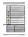
!
The user is strongly cautioned to read Appendix B, “Regulatory Notices and Safety
Information”. Important safety cautions, warnings and regulatory information is contained in
Appendix B.
Important: This symbol is placed on the product to remind users to dispose of Waste Electrical
and Electronic Equipment (WEEE) appropriately, per Directive 2002-96-EC. In most areas, this
product can be recycled, reclaimed and re-used when properly discarded. Do not discard labeled
units with trash. For information about proper disposal, contact LXE through your local sales
representative, or visit www.lxe.com.
Table of Contents
THE VX8 VEHICLE MOUNT COMPUTER
1
Introduction ............................................................................................................... 1
Document Conventions ............................................................................................................2
Environmental Specifications...................................................................................................2
Quick Start................................................................................................................. 3
Components .............................................................................................................. 4
The Full-Screen Display ........................................................................................... 6
Microsoft Windows Control Panel........................................................................... 6
The Keyboards .......................................................................................................... 7
LXE 95-key QWERTY Keyboard with Pointing Device.........................................................8
Key Maps ...............................................................................................................................8
NumLock and the VX8.................................................................................................................... 8
CapsLock, Scroll Lock and the VX8 ............................................................................................... 8
Keyboard Backlight................................................................................................................9
LXE 60-key QWERTY Keyboard..........................................................................................10
Key Maps .............................................................................................................................10
Unused Key Functions .........................................................................................................11
NumLock and the VX8 ........................................................................................................11
Keyboard Backlight..............................................................................................................11
Keyboard LEDs....................................................................................................................11
CAPS LED..................................................................................................................................... 12
Secondary Keys LED..................................................................................................................... 12
Control Keys ........................................................................................................................13
General Windows Keyboard Shortcuts ..................................................................................14
Non-LXE Keyboard/Mouse....................................................................................................15
Software Keyboard .................................................................................................................15
Power Supply .......................................................................................................... 16
Uninterruptible Power Supply Battery Pack ..........................................................................16
Getting Help............................................................................................................. 17
Manuals and Accessories ...................................................................................... 17
Manuals...................................................................................................................................17
Accessories .............................................................................................................................17
INSTALLATION
19
Install Mounting Brackets ...................................................................................... 19
RAM Mount System...............................................................................................................20
E-EQ-VX8OGWW-A
VX8 User’s Guide
ii
Table of Contents
Mounting Procedure ...............................................................................................................21
Step 1 – Mount Vehicle RAM Ball(s)..................................................................................21
Step 2 – Prepare VX8...........................................................................................................22
Step 3 – Attach Keyboard to Bracket...................................................................................24
Step 4 – Attach VX8 and Keyboard Assembly to RAM Base.............................................25
Completed Assembly..............................................................................................................26
Removing the Port Lid............................................................................................ 27
Connect Keyboard .................................................................................................. 28
LXE VMT Keyboard..............................................................................................................28
Non-LXE Keyboard or Mouse ...............................................................................................28
Connect Serial Barcode Scanner .......................................................................... 29
Connect USB Devices............................................................................................. 30
Internal USB Port ...................................................................................................................30
External USB Port ..................................................................................................................30
Connect Ethernet Cable ......................................................................................... 31
Connect External Headset...................................................................................... 31
Connect Power Cable ............................................................................................. 32
External AC Power Supply, Optional.....................................................................................32
Vehicle 12-80VDC Power Connection ..................................................................................33
Connecting Cables to Power Sources...................................................................................33
Wiring Schematic without Blackout Screen Box .......................................................................... 35
Wiring Schematic with Blackout Screen Box................................................................................ 36
Strain Relief Cable Clamps .................................................................................... 37
Cable Protection Tube ............................................................................................ 37
Securing Port Lid .................................................................................................... 38
OPERATION
39
Powering On/Off...................................................................................................... 39
Reset Key Sequence (Reboot) ................................................................................................40
Keyboard Backlight ................................................................................................ 41
95 Key Keyboard....................................................................................................................41
60 Key Keyboard....................................................................................................................41
PS/2 Keyboard ........................................................................................................................41
Display and Touchscreen....................................................................................... 42
Adjusting Screen Display .......................................................................................................42
Cleaning the Display ..............................................................................................................42
Calibrating the Touchscreen ...................................................................................................43
Power Management ................................................................................................ 43
Laser Barcode Scanner Warnings......................................................................... 44
VX8 User’s Guide
E-EQ-VX8OGWW-A
Table of Contents
iii
Enter Data ................................................................................................................ 44
Keyboard Entry.......................................................................................................................45
Touchscreen Entry ..................................................................................................................45
Scanner Entry..........................................................................................................................46
Aiming the Barcode Scanner................................................................................................46
Distance from Label .............................................................................................................46
Successful Scan ....................................................................................................................46
Unsuccessful Scan................................................................................................................46
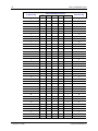
APPENDIX A KEY MAPS
47
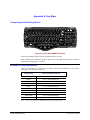
95-key Keypad with Pointing Device ..................................................................... 47
Key Map 101-Key Equivalencies...........................................................................................47
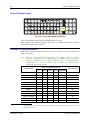
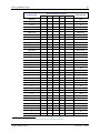
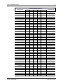
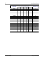
60-key Standard Keypad ........................................................................................ 48
Key Map 101-Key Equivalencies...........................................................................................48
APPENDIX B REGULATORY NOTICES AND SAFETY INFORMATION
53
INDEX
59
Illustrations
Figure 1 VX8 Components, Bottom ....................................................................................................................4
Figure 2 VX8 Components, Top..........................................................................................................................4
Figure 3 VX8 Components, Front .......................................................................................................................5
Figure 4 The LXE VMT Keyboards with Cable..................................................................................................7
Figure 5 The 95-key QWERTY Keyboard ..........................................................................................................8
Figure 6 The 60-key QWERTY Keyboard ........................................................................................................10
Figure 7 Keyboard LEDs ...................................................................................................................................11
Figure 8 The CapsLock Key ..............................................................................................................................12
Figure 9 The Secondary Key .............................................................................................................................12
Figure 10 The VMT Keyboard Display Controls ..............................................................................................13
Figure 11 Virtual Keyboard, Sample Configuration..........................................................................................15
Figure 12 Sample RAM Ball Mounting Options ...............................................................................................21
Figure 13 Screw Installation, VX8 ....................................................................................................................22
Figure 14 Attach Keyboard to Mounting Plate ..................................................................................................24
Figure 15 Completed RAM Mount Assembly ...................................................................................................26
Figure 16 Removing the Port Lid ......................................................................................................................27
Figure 17 Keyboard and Mouse Connectors......................................................................................................28
Figure 18 LXE Keyboards with Adapter Cable.................................................................................................28
Figure 19 Connect Serial Scanner Cable ...........................................................................................................29
Figure 20 Generic Barcode Scanner ..................................................................................................................29
Figure 21 External USB Ports............................................................................................................................30
Figure 22 Connect Ethernet Cable .....................................................................................................................31
Figure 23 Connect External Headset .................................................................................................................31
Figure 24 Connect Power Cable to VX8 ...........................................................................................................32
E-EQ-VX8OGWW-A
VX8 User’s Guide
iv
Table of Contents
Figure 25
Figure 26
Figure 27
Figure 28
Figure 29
Figure 30
Figure 31
Figure 32
Figure 33
Figure 34
Figure 35
Figure 36
Figure 37
Figure 38
Figure 39
Optional AC Power Supply ...............................................................................................................32
DC to DC Converter..........................................................................................................................34
Screen Blackout Box .........................................................................................................................35
Power Cable Routing without Blackout Screen Box.........................................................................35
Power Cable Routing with Blackout Screen Box..............................................................................36
Strain Relief Brackets........................................................................................................................37
Applying Cable Protection Tube .......................................................................................................37
Mounting the Port Lid .......................................................................................................................38
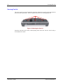
The VX8 Power Switch.....................................................................................................................39
Screen Brightness Controls ...............................................................................................................42
Caution Labels Class II Scanner........................................................................................................44
Caution Labels Class IIIA Scanner ...................................................................................................44
Scan Beam .........................................................................................................................................46
95-Key VMT QWERTY Keyboard ..................................................................................................47
60-Key VMT QWERTY Keyboard ..................................................................................................48
VX8 User’s Guide
E-EQ-VX8OGWW-A
The VX8 Vehicle Mount Computer
Introduction
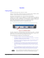
The VX8 Vehicle Mount Computer (VMC) is a rugged, vehicle-mounted, PC (Personal
Computer) equipped with a Microsoft® Windows® operating system. The VX8 is capable of
wireless data communications from a fork-lift truck or any properly configured vehicle. The unit
uses a PCMCIA radio (spread spectrum 2.4GHz) for wireless data communications.
The VX8 is a tablet-style computer and features a SVGA color TFT display. The touch-screen
display supports graphic features and Microsoft Windows icons that the Windows XP operating
system supports. An illuminated keyboard is available to facilitate use in dimly lit areas.
The VX8 provides the power and functionality of a desktop computer in a vehicle mounted unit,
with a wide range of options:
Note:
E-EQ-VX8OGWW-A
•
600MHz or 1.0GHz Intel® Celeron® or 1.4GHz Intel® Pentium® CPU
•
512 or 1024MB of SDRAM
•
Wireless options include 802.11abg, 802.11bg, Bluetooth®, and WAN. All options
may not be available in all areas.
•
Ethernet port
•
USB port
•
Choice of storage media
•
SVGA display
•
Standard, hardened and defroster touch screen options
•
Built in Uninterruptible Power Supply (UPS)
•
RAM MountTM options
The “VX8 Reference Guide” contains VX8 technical information and advanced
functions.
VX8 User’s Guide
2
Introduction
Document Conventions
This reference guide uses the following document conventions:
ALL CAPS
Menu|Choice
“Quotes”
<
>
All caps are used to represent disk directories, file names, and application
names.
Rather than use the phrase “choose the Save command from the File menu”,
this manual uses the convention “choose File|Save”.
Indicates the title of a book, chapter or a section within a chapter (for
example, “Document Conventions”).
Indicates a key on the keyboard (for example, <Enter> ).
Indicates a reference to other documentation.
Differences in operation or commands due to radio type.
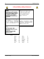
ATTENTION
!
Keyword that indicates vital or pivotal information to follow.
Attention symbol that indicates vital or pivotal information to follow. Also,
when marked on product, means to refer to the manual or operator’s guide.
International fuse replacement symbol. When marked on the product, the
label includes fuse ratings in volts (v) and amperes (a) for the product.
Note:
Caution
Keyword that indicates immediately relevant information.
Keyword that indicates a potentially hazardous situation, which, if not
avoided, may result in minor or moderate injury.
!
WARNING
!
DANGER
!
Keyword that indicates a potentially hazardous situation, which, if not
avoided, could result in death or serious injury.
Keyword that indicates an imminent hazardous situation, which, if not
avoided, will result in death or serious injury.
Environmental Specifications
Feature
Specification
Operating Temperature
-4°F to 122°F (-20°C to 50°C) [non-condensing]
Storage Temperature
-22°F to 122°F (-30°C to 50°C) [non-condensing]
Water, Sand Dust
IP65 per IEC60529
Vibration tested
According to: IEC 60068-2-64, Test Fh Vibration
Shock tested
According to: IEC 60068-2-29, Test Eb Bump
Moisture tested
According to: IEC 60068-2-30, Test Db
VX8 User’s Guide
E-EQ-VX8OGWW-A
Quick Start
3
Quick Start
This section’s instructions are based on the assumption that your new system is pre-configured
and requires only accessory installation (e.g. antenna, external keyboard and/or barcode scanner)
and a power source.
Use this guide as you would any other source book -- reading portions to learn about the VX8,
and then referring to it when you need more information about a particular subject. This guide
takes you through installation and operation of the LXE VX8.
In general, the sequence of events is:
1.
Install Vehicle Mounting Bracket (and keyboard mounting bracket) on vehicle.
2.
Secure VX8 in Mounting Bracket Assembly.
3.
Connect power cable to the VX8. Connect DC to DC converter and optional screen
blanking box.
4.
Connect DC to DC converter to vehicle power.
5.
Connect accessories to VX8, e.g. scanner, antenna, keyboard.
6.
Secure all cables.
7.
Turn the VX8 on.
The VX8 and its keyboard should be mounted in an area in the vehicle where it:
E-EQ-VX8OGWW-A
•
Does not obstruct the vehicle driver’s vision or safe vehicle operation.
•
Can be easily accessed by anyone seated in the driver’s seat.
VX8 User’s Guide
4
Components
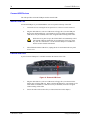
Components
1
2
3
4
5
6
7
8
9 10 11 12
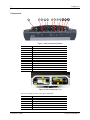
Figure 1 VX8 Components, Bottom
Position
Function
1
2
3
4
5
6
7
8
9
10
11
12
Power supply (12V DC 50W)
Mic. in
Audio out
COM2 RS232 +12V
COM1 RS232 +5V
VGA (external monitor)
Multipurpose connector (USB 2.0, RS232, +12 V)
RJ-45 Ethernet 10/100 (LAN)
2x USB 2.0
PS/2 Mouse
PS/2 Keyboard
Bluetooth antenna connector
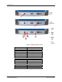
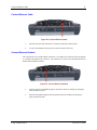
Figure 2 VX8 Components, Top
The service lid has been removed to show components.
Position
1
2
3
4
5
6
VX8 User’s Guide
Function
USB 2.0
Hard drive
Compact Flash slot (behind HD cable)
Battery/UPS
Mini PCI slot
PC Card slot (option)
E-EQ-VX8OGWW-A
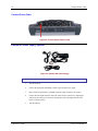
Components
5
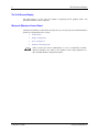
On/Off
Button
Screen
Brightness
1. Power
LED
2. UPS
Mode
LED
1
3
4
2
3. Hard
Drive
LED
4. Light
Sensor
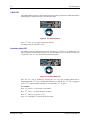
Figure 3 VX8 Components, Front
Function
Off and not powered
Off but powered
Operating normally
Suspend
Black-out Screen
Over voltage shutdown
Over temperature
Power LED
Off (no light)
Green flash very slow
Green on
Green flashing slow
Green flashing fast
Red on
Red flashing
Function
UPS battery powered
UPS battery charging
UPS battery charged
UPS Mode LED
Green flashing fast
Green on or flashing slow
Off (no light)
Function
Hard drive activity
No activity
Hard Drive LED
Green flashing
Off (dark)
E-EQ-VX8OGWW-A
VX8 User’s Guide
6
The Full-Screen Display
The Full-Screen Display
The VX8 Display is a TFT color unit capable of supporting SVGA graphics modes. The
maximum resolution is 800 x 600 pixels.
Microsoft Windows Control Panel
The Microsoft Windows Control Panel and System Tray icons panel provide standard Windows
options for configuring the VX8, such as:
•
Sound volume
•
Display configuration
•
Power management
•
PCMCIA card management
Please consult your System Administrator or refer to commercially available
Microsoft Windows user guides or the Windows on-line Help application for
these standard Windows configuration options.
VX8 User’s Guide
E-EQ-VX8OGWW-A
The Keyboards
7
The Keyboards
The following keyboard options are available for the VX8:
•
LXE VMT 95-key QWERTY keyboard with integrated pointing device – a
customized rugged keyboard connected to the VX8 via an adapter cable.
•
LXE VMT 60-key QWERTY keyboard – a customized rugged keyboard connected
to the VX8 via an adapter cable.
•
A keyboard and mouse with standard PS/2 connectors via the PS/2 ports on the
VX8.
•
A software keyboard, or virtual keyboard, can be displayed on the touch screen. The
virtual keyboard can be used in place of, or in addition to, a physical keyboard.
For more details on each keyboard type, please refer to the appropriate section later in this section.
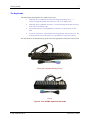
95 key with Integrated Pointing Device
60 key
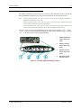
Figure 4 The LXE VMT Keyboards with Cable
E-EQ-VX8OGWW-A
VX8 User’s Guide
8
The Keyboards
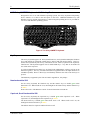
LXE 95-key QWERTY Keyboard with Pointing Device
Designed for ease of use with Windows operating systems, the 95-key keyboard with pointing
device connects via a cable to the PS/2 ports on the VX8. Additional Windows keys (the
Windows logo key and the Application key) and an integrated pointing device are provided for
ease of use with Windows operating systems.
Esc
~
`
Tab
Caps
Lock
Shift
Ctrl
F1
F2
!
1
F3
#
3
@
2
Q
W
A
Z
$
%
4
5
E
S
R
D
X
F5
F4
C
H
I
J
N
0
O
K
M
Alt
<
,
+
=
{
[
P
:
;
L
>
.
Alt
Print
Screen
SysRq
F12
_
-
)
9
U
F11
F10
(
8
Y
B
F9
*
7
G
V
F8
&
^
6
T
F
F7
F6
}
]
"
'
?
/
BackSpace
|
\
Enter
Shift
Scroll
Lock
Break
Num
Lock
/
*
-
7
8
9
+
4
5
6
1
2
Home
End
Ctrl
0
Ins
L
Fn
Pause
PgUp
3
PgDn
.
Del
Enter
R
Figure 5 The 95-key QWERTY Keyboard
Key Maps
The 95-key keyboard supports all 104 keyboard functions (101 keyboard standard plus Windows
keys) and includes an integrated pointing device and left and right mouse buttons. However,
because the keyboard only has 95 keys, all functions are not visible (or printed on the keyboard).
Therefore the VX8 keyboard supports what is called hidden keys -- keys that are accessible but
not visible on the keyboard.
As with a standard keyboard, many keys are found in the Alphanumeric section as well as on the
Numeric keypad (i.e. the 1 key is found on the numeric keypad and above the alpha characters on
standard keyboards). However these keys send distinctly different scan codes when the keys are
pressed.
The hidden keys supported by the VX8 are listed in Appendix A, “Key Maps”.
NumLock and the VX8
For the 95-key keyboard, the NumLock key and the numeric keys are backlit green when
NumLock is off. When NumLock is on, the backlight for the NumLock key and the numeric keys
is amber.
Please refer to the “VX8 Reference Guide” for more information on NumLock.
CapsLock, Scroll Lock and the VX8
For the 95-key keyboard, the CapsLock key is backlit green when CapsLock is off. When
CapsLock is on, the backlight for the CapsLock key is amber.
The Scroll Lock key is backlit green when Scroll Lock is off. When Scroll Lock is on, the
backlight for the Scroll Lock key is amber.
The default values for CapsLock and Scroll Lock are Off.
VX8 User’s Guide
E-EQ-VX8OGWW-A
The Keyboards
9
Keyboard Backlight
The 95-key keyboard backlights each key with an LED. The keyboard backlight is
manually controlled using the “backlight” key in the upper right hand corner of the
keyboard. Pressing the backlight key cycles the keyboard backlight through the levels of
backlight intensity:
Note:
E-EQ-VX8OGWW-A
•
Off
•
Maximum intensity
•
Medium intensity
•
Low intensity.
The 2nd key function is available on the 60-key keyboard only.
VX8 User’s Guide
10
The Keyboards
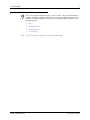
LXE 60-key QWERTY Keyboard
The 60-key keyboard has 101 keyboard functions, including a numeric keyboard pad. Please refer
to Appendix A, “Key Maps”, for keypress combinations.
ESC
CTRL
SHIFT
ALT
2ND
CAPS
BREAK
R/S
F1
F2
F3
@
!
|
SP
E
;
\
A
$
#
W
BKLT
%
R
F5
F4
&
^
T
:
D
F
G
Z
X
C
V
(
*
,
I
.
H
J
B
N
K
P
PgUp
L
Home
M
F9
)
O
?
_
~
F8
F7
U
Y
‘
S
F6
PgDn
CAPS
/
2nd
=
F10
INS
BKSP
ENTER
END
[
<
7
4
1
0
{
]
8
5
2
+
}
>
9
6
3
DEL
.
Figure 6 The 60-key QWERTY Keyboard
Key Maps
The 60-key keyboard supports all 101 keyboard functions. However, because the keyboard only
has 60 keys, all functions are not visible (or printed on the keyboard). Therefore the VX8
keyboard supports what is called hidden keys -- keys that are accessible but not visible on the
keyboard.
On standard keyboards many keys are found in the Alphanumeric section as well as on the
Numeric keypad (i.e. the 1 key is found on the numeric keypad and above the alpha characters on
standard keyboards). However these keys send distinctly different scan codes when the keys are
pressed. The default codes for the VX8 number keys correspond to the numeric keypad on
standard keyboards. In order to duplicate the codes sent when the alphanumeric key is pressed, the
hidden keystroke must be used.
The hidden keys supported by the VX8 are listed in Appendix A, “Key Maps”.
VX8 User’s Guide
E-EQ-VX8OGWW-A
The Keyboards
11
Unused Key Functions
There are several key functions on the 60-key keyboard that are not used on the VX8. These
include:
•
<2nd> <F3> – The Resume/Suspend function is not used as Microsoft Windows
controls all power management modes.
•
<2nd> <F4> and <2nd> <F5> – The Display Brightness functions are not used as
the display brightness is adjusted by the buttons on the VX8.
•
<2nd> <F6> and <2nd> <F7> – The Contrast functions are not used as the contrast
is not adjustable on the TFT display on the VX8.
•
<2nd> <F8> and <2nd> <F9> – The Volume control keys are not used as volume is
adjusted via the Microsoft Windows Volume icon in the System Tray.
•
<2nd> <F10> – Please see “Keyboard Backlight” later in this section for details on
toggling the keyboard backlight.
NumLock and the VX8
The 60-key keyboard does not have a NumLock indicator or key. NumLock can be toggled On
or Off using the <2nd> <SHIFT> <F10> keypress sequence.
Please refer to the “VX8 Reference Guide” for more information on NumLock.
Keyboard Backlight
The LXE keyboard keys are backlit with LEDs. The backlight is manually controlled using the
<2nd> + <CTRL> + <F10> keypress sequence.
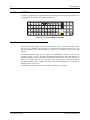
Keyboard LEDs
The VX8 keyboard has two (2) LED indicators.
KLT
CAPS
F10
INS
BKSP
2nd
ENTER
END
/
=
[
<
7
1. CapsLock Mode LED
Indicator
4
1
2. Secondary Mode LED
Indicator
0
Figure 7 Keyboard LEDs
E-EQ-VX8OGWW-A
VX8 User’s Guide
12
The Keyboards
CAPS LED
This LED indicates the state of the keyboard CapsLock mode. If CapsLock is enabled this LED is
illuminated green. When CapsLock is off, the LED is dark.
D
CAPS
F1
B
Figure 8 The CapsLock Key
Press <2nd> then <F1> to toggle CapsLock On and Off.
The default value of CapsLock is “Off”.
Secondary Keys LED
The VMT keyboard is equipped with several secondary keys. These keys are identified by the
superscripted text found on the keyboard keys. The secondary keys are accessible by using two
(2) keystrokes: the <2nd> key followed by the superscripted key.
C
2ND
C
Figure 9 The Secondary Key
Once the <2nd> state is enabled (by pressing the <2nd> key) the Secondary Mode LED is
illuminated and the <2nd> state is enabled until another key is pressed. The <2nd> key is toggled on
with a <2nd> keypress and then immediately off with another <2nd> keypress.
For example:
Press <2nd> and <F1> to turn CapsLock on and off.
Press <2nd> and <↑> to initiate the PgUp command.
Press <2nd> and <Q> to type the “!” key.
Press <2nd> and <BkSp> to enter the Insert (Ins) mode.
VX8 User’s Guide
E-EQ-VX8OGWW-A
The Keyboards
13
Control Keys
The VMT keyboard has several control keys. Because of the construction of the VX8 and the
Microsoft Windows operating system, many of the Control Keys are not used on the VX8.
Note:
The 2nd functions of the <F4> and <F5>keys are not used as the display brightness is
adjusted via the buttons on the VX8.
The 2nd functions of the <F6>, and <F7> keys are not used as the VX8 has TFT LCD
screen with no provision for contrast adjustments.
The 2nd functions of the <F8> and <F9> keys are not used as the sound volume on the
VX8 is controlled with the Sound icon in the Microsoft Windows System Tray.
The <F10> key is used to toggle the backlight as part of the keypress sequence <2nd> + <CTRL>
+ <F10>. This key sequence immediately toggles the status of the keyboard backlight. Pressing
<2nd> + <F10> has no effect on the keyboard backlight.
1. Display Brightness
Control Keys (Not
used)
BKLT
R/S
F3
F4
F5
F6
F7
F8
F9
F10
2. Display Contrast
Control Keys (Not
used)
3. Speaker Volume
Control Keys (Not
used)
4. Backlight Control
Key (See above)
Figure 10 The VMT Keyboard Display Controls
E-EQ-VX8OGWW-A
VX8 User’s Guide
14
The Keyboards
General Windows Keyboard Shortcuts
Use the keyboard shortcuts in the chart below to navigate with any VX8 keyboard. These are
standard keyboard shortcuts for Windows applications.
Press these keys …
To …
CTRL + C
Copy
CTRL + X
Cut
CTRL + V
Paste
CTRL + Z
Undo
DELETE
Delete
SHIFT with any of the arrow keys
Select more than one item in a window or on the
desktop, or select text within a document.
CTRL+A
Select all.
ALT+ESC
Cycle through items in the order they were opened.
CTRL+ESC
Display the Start menu.
ALT+Underlined letter in a menu
name
Display the corresponding menu.
Underlined letter in a command
name on an open menu
Carry out the corresponding command.
ESC
Cancel the current task.
The touchscreen provides equivalent functionality to a mouse:
VX8 User’s Guide
•
A touch on the touchscreen is equivalent to a left mouse click.
•
Many items can be moved by the “drag and drop” method, touching the desired item,
moving the stylus across the screen and releasing the stylus in the desired location.
•
A double stylus tap is equivalent to a double click.
•
Right click is generated by tapping the mouse icon in the system tray. After tapping,
the mouse icon highlights the right button of the icon in red. The next touchscreen
tap is treated as a right click. The mouse icon then returns to the left button
highlighted in red so subsequent taps are treated as left clicks.
E-EQ-VX8OGWW-A
The Keyboards
15
Non-LXE Keyboard/Mouse
The VX8 accepts a PS/2 keyboard and/or mouse attached to the VX8 using the PS/2 ports. Please
refer to documentation provided with the PS/2 keyboard and mouse for more information on their
operation.
Software Keyboard
The optional software keyboard provides a virtual keyboard on the touchscreen.
keyboard is available in several configurations.
The soft
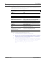
Figure 11 Virtual Keyboard, Sample Configuration
Note:
E-EQ-VX8OGWW-A
When the virtual keyboard is displayed, the physical keyboard is still active, if attached.
Therefore it is possible to input data from both keyboards.
VX8 User’s Guide
16
Power Supply
Power Supply
Vehicle power input for the VX8 is dependent on the power supply selected. Availability of
power supplies may vary by region:
VX89A301PSDC9TO36V, Power Supply, DC/DC for 9-36V trucks, 60W
VX89A302PSDC48V, Power Supply, DC/DC for 18-60V trucks, 60W
VX89A303PSDC60TO110V, Power Supply, DC/DC for 50-150V trucks, 60W
Important – A DC to DC power supply is required to provide a conditioned power source to the
VX8. The VX8 cannot be connected to vehicle power without the DC to DC power supply.
If DC power is not available – for example, in an office environment – an optional external Input
Power Supply can be used to convert AC wall power to an appropriate DC level. See the section
titled “Installation”, sub-section titled “External Power Supply.”
Uninterruptible Power Supply Battery Pack
An Uninterruptible Power Supply (UPS) is built into the VX8 to provide power for short periods
of time when vehicle power is unavailable (such as when vehicle batteries are swapped). The
UPS, when enabled, can be used to power the VX8 for a specified period of time before
shutdown.
Configuration of the UPS is handled via the VMT Manager option in the Control Panel. For more
information consult the VX8 Reference Guide or the system administrator responsible for the
configuration of the VX8.
VX8 User’s Guide
E-EQ-VX8OGWW-A
Getting Help
17
Getting Help
All LXE manuals are now available on one CD and they can also be viewed/downloaded
from the LXE website. Contact your LXE representative to obtain the LXE Manuals CD.
You can also get help from LXE by calling the telephone numbers listed on the LXE Manuals
CD, in the file titled “Contacting LXE”. This information is also available on the LXE website
www.lxe.com.
Explanations of terms and acronyms used in this guide are located in the file titled “Glossary” on
the LXE Manuals CD.
Manuals and Accessories
Manuals
The following manuals are available on the LXE Manuals CD:
•
VX8 Reference Guide
•
Contacting LXE
•
LXE Technical Glossary
Accessories
LXE carries a full line of accessories for the VX8. For information on these accessories, please
refer to the VX8 & VX9 accessory catalog. This catalog is available at www.lxe.com or by
contacting your LXE representative.
E-EQ-VX8OGWW-A
VX8 User’s Guide
18
VX8 User’s Guide
Manuals and Accessories
E-EQ-VX8OGWW-A
Installation
Install Mounting Brackets
Caution:
This device is intended to transmit RF energy. For protection against RF exposure
to humans and in accordance with FCC rules and Industry Canada rules, this
transmitter should be installed such that a minimum separation distance of at least
20 cm (7.8 in.) is maintained between the antenna and the general population.
This device is not to be co-located with other transmitters.
Several types of mounts are provided for the VX8. For a complete listing of mounting kits and
the contents of each kit, please refer to the VX8 & VX9 accessory catalog. This catalog is
available at www.lxe.com or by contacting your LXE representative.
VX8 with single RAM ball option
If the VX8 is ordered with a single RAM ball, available mounting options include:
•
Truck bracket with a single RAM ball (no keyboard mount provision)
•
Truck bracket with a RAM ball for VX8 mount plus a RAM ball for keyboard mount
•
RAM ball base with integrated keyboard bracket for back of VX8.
VX8 with dual RAM ball option
If the VX8 is ordered with dual RAM balls, available mounting options include:
•
Truck bracket with a dual RAM balls (no keyboard mount provision)
•
Truck bracket with dual RAM balls for VX8 mount plus a RAM ball for keyboard
mount
Keyboard mounting options
They keyboard may be mounted using:
•
Integrated keyboard bracket included in some single RAM ball mounting kits
•
A RAM mount using the keyboard ball on some truck brackets
•
A stand alone keyboard mount using a RAM ball attached to the vehicle
Individual brackets
Many individual mounting brackets are also available.
E-EQ-VX8OGWW-A
VX8 User’s Guide
20
Install Mounting Brackets
RAM Mount System
The following RAM balls are used to mount the VX8:
D-sized (2.25”) balls and arms
Used to mount the VX8 when a single RAM ball is ordered on the back of the VX8. A D-sized
ball is also used on the truck.
C-sized (1.5”) balls and arms
Used to mount the VX8 when dual RAM balls are ordered on the back of the VX8. A pair of Csized balls is also used on the truck.
Keyboard brackets also use C-sized ball. A corresponding C-sized ball is either included as part
of the VX8 mounting bracket or mounted independently on the truck for the keyboard assembly.
VX8 User’s Guide
E-EQ-VX8OGWW-A
Install Mounting Brackets
21
Mounting Procedure
Step 1 – Mount Vehicle RAM Ball(s)
Determine the position for mounting the RAM ball(s). Be sure to position the RAM ball(s) to
allow access to the switches and ports on the bottom of the VX8.
Depending on the options ordered with the VX8, the RAM ball may be:
•
A single or dual RAM ball mounted directly to the truck
•
A single or dual RAM ball mounted to a plate. The plate then mounts to the truck.
•
A single RAM ball integrated with a mounting plate
•
A single or dual RAM squeeze clamp style ball
•
A single or dual RAM pipe clamp style ball
Additionally, some mounting plates contain a provision for another RAM ball which is used to
mount the keyboard.
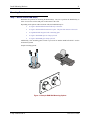
Sample mounting options:
Figure 12 Sample RAM Ball Mounting Options
E-EQ-VX8OGWW-A
VX8 User’s Guide
22
Install Mounting Brackets
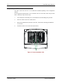
Step 2 – Prepare VX8
The VX8 is delivered with one or two RAM balls installed depending on the configuration
ordered.
If an integrated keyboard bracket is to be mounted to the rear of the VX8, follow the procedure
below. Otherwise, skip to the next step.
1.
The VX8 must be off and the power cord should not be attached during this procedure.
2.
Place the VX8 face down on a stable surface.
3.
Remove the RAM ball from the back of the VX8. The hardware attaching the RAM ball
is not reused.
4.
Install the 2 M5x6 screws in the holes shown below.
Figure 13 Screw Installation, VX8
VX8 User’s Guide
E-EQ-VX8OGWW-A
Install Mounting Brackets
23
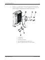
5.
Install the 1.5” (C-size) RAM ball on the keyboard bracket using four M5 locking nuts.
6.
Install the keyboard bracket and the 2.25” (D-Size) RAM ball (removed previously) onto
the back of the VX8. Use three M5x20 screws with three tapered washers.
E-EQ-VX8OGWW-A
1.
1.5” RAM ball
2.
Locking nut, M5
3.
Integrated keyboard bracket
4.
Screw, M5x20 (DO NOT reuse original screws)
5.
Washer for RAM ball (DO NOT reuse original washers)
VX8 User’s Guide
24
Install Mounting Brackets
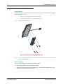
Step 3 – Attach Keyboard to Bracket
LXE Keyboards
If using the optional integrated keyboard mount, attach the keyboard to keyboard mounting plate,
using the appropriate screws:
Note:
•
For the 95 key keyboard, use four 8-32x5/8 screws
•
For the 60 key keyboard, use four 10-32x5/8 screws
95-key LXE keyboard shown.
Figure 14 Attach Keyboard to Mounting Plate
Note
Excess keyboard cable length can be looped around the hooks on the bottom of the
keyboard mounting plate.
Other Keyboards
A generic keyboard plate is provided for non-LXE keyboards.
1.
Attach the RAM ball to the keyboard mounting plate.
2.
Attach the keyboard to the keyboard mounting plate. The mounting kit DOES NOT include
hardware to attach the keyboard to the plate.
VX8 User’s Guide
E-EQ-VX8OGWW-A
Install Mounting Brackets
25
Step 4 – Attach VX8 and Keyboard Assembly to
RAM Base
Single RAM ball
1.
Use a single D-sized RAM arm to attach the VX8 assembly to the RAM ball on the vehicle.
2.
Use a single C-sized RAM arm to attach the keyboard assembly to the C-sized ball on either
the VX8 keyboard bracket or a C-sized ball on the vehicle.
Dual RAM balls
1.
Use a pair of C-sized arms to attach the VX8 assembly to the RAM balls on the vehicle.
2.
Use a C-sized arm to attach the keyboard assembly to a C-sized ball on the vehicle.
E-EQ-VX8OGWW-A
VX8 User’s Guide
26
Install Mounting Brackets
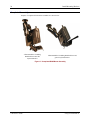
Completed Assembly
Samples of completed VX8 bracket assemblies are shown below
VX89A021KIT21 including
RAM ball base and LXE
keyboard bracket
VX89A025KIT25 including RAM ball base and
generic keyboard bracket
Figure 15 Completed RAM Mount Assembly
VX8 User’s Guide
E-EQ-VX8OGWW-A
Removing the Port Lid
27
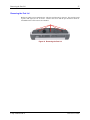
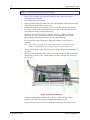
Removing the Port Lid
Before any cables can be attached to the VX8, the port lid must be removed. The port lid is held
in place with eight (8) Torx 20 screws. Remove the screws and the port lid and set aside for
reinstallation once all accessories are attached.
Figure 16 Removing the Port Lid
E-EQ-VX8OGWW-A
VX8 User’s Guide
28
Connect Keyboard
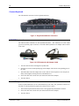
Connect Keyboard
The VX8 has PS/2 connectors for the keyboard and mouse.
Figure 17 Keyboard and Mouse Connectors
LXE VMT Keyboard
The VX8 has PS/2 connectors for the keyboard and mouse. The connectors are color coded
(green for keyboard, purple for mouse). The LXE VMT keyboards use an adapter cable to attach
to the VX8.
Figure 18 LXE Keyboards with Adapter Cable
1.
Turn the VX8 off before attaching the keyboard cable.
2.
Insert the PS/2 mouse and keyboard plugs on the adapter cable into the corresponding port on
the VX8
3.
Attach the other end of the adapter cable to the connector on the keyboard. Once the pins are
firmly seated, tighten (turning clockwise) the thumbscrews.
4.
Secure the cable with a strain relief (see instructions later in this chapter).
5.
Turn the VX8 on.
Non-LXE Keyboard or Mouse
A PS/2 keyboard and mouse can be connected directly to the VX8. The green PS/2 connector on
the VX8 is for the keyboard, the purple PS/2 connector is for a mouse.
1.
Attach a PS/2 keyboard and/or PS/2 mouse to the appropriately labeled PS/2 connector.
2.
Secure the cable with a strain relief (see instructions later in this chapter).
3.
Turn the VX8 on.
VX8 User’s Guide
E-EQ-VX8OGWW-A
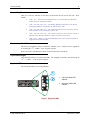
Connect Serial Barcode Scanner
29
Connect Serial Barcode Scanner
!
Refer to the documentation received with the barcode scanner for complete
instructions. Read all warnings and caution labels.
Please note Pin 9 of COM2 provides +12V and should not be used for a scanner
that requires 5V.
Pin 9 of COM1 must be configured to provide +5V. An LED illuminates near the COM1
connector when the +5V option is enabled. The LED is off when RI is enabled.
Configuration of COM port power is handled via the VMT Manager option in the Control
Panel. For more information consult the VX8 Reference Guide or the system administrator
responsible for the configuration of the VX8.
The scanner cable is attached to the COM1 port. The cable requires a nine-pin D-shell female
connector for the VX8.
Note:
Use of a shielded cable is required to maintain FCC and CISPR22 emissions
compliance.
Figure 19 Connect Serial Scanner Cable
1.
Seat the connector firmly over the pins and turn the thumbscrews in a clockwise
direction. Do not overtighten.
When you have finished using the scanner, remove it from the VX8 and store the scanner in a
closed container or bag.
1. Good Scan LED (or equivalent)
2. Trigger
3. Laser Aperture at Front
Figure 20 Generic Barcode Scanner
Refer to the documentation received with the barcode scanner for complete
instructions.
E-EQ-VX8OGWW-A
VX8 User’s Guide
30
Connect USB Devices
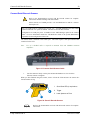
Connect USB Devices
The VX8 provides an internal USB port and an external USB.
Internal USB Port
An internal USB port is provided behind the user access panel on the top of the VX8.
1.
Loosen the screws securing the access panel cover so the cover can be removed.
2.
Plug the desired device, such as a USB mouse or floppy drive, into the USB port.
Refer to the documentation for your USB device for more details on installation.
USB devices may be installed, removed or swapped without turning off the VX8.
!
3.
While the access panel is open, the VX8 IS NOT environmentally sealed.
The internal USB port should only be used when the VX8 is in a clean,
dry, dust free environment. Use the external USB port if a USB device
must be used in a harsh environment.
When finished with the USB device, unplug the device and reattach the user panel
access cover.
External USB Port
A pair of external USB ports is available located on the bottom of the VX8.
Figure 21 External USB Ports
VX8 User’s Guide
1.
Plug the desired device, such as a USB mouse or floppy drive, into the end of the
dongle cable with the USB port. Refer to the documentation for your USB device for
more details on installation. USB devices may be installed, removed or swapped
without turning off the VX8.
2.
Secure the cable with a strain relief (see instructions later in this chapter).
E-EQ-VX8OGWW-A
Connect Ethernet Cable
31
Connect Ethernet Cable
Figure 22 Connect Ethernet Cable
1.
Insert the network cable and ensure it is firmly seated in the connector jack.
2.
To remove the Ethernet cable, press the release tab on the cable end.
Connect External Headset
The VX8 provides an external headset connection via an audio jack connector and a microphone
to a separate microphone jack connector. The connectors are color keyed and marked with the
headset and microphone symbols.
Figure 23 Connect External Headset
1.
Insert the speaker or headphone plug into the audio connector; making sure the plug is
firmly seated in the jack.
2.
Insert the microphone plug into the microphone connector; making sure the plug is
firmly seated in the jack.
E-EQ-VX8OGWW-A
VX8 User’s Guide
32
Connect Power Cable
Connect Power Cable
Figure 24 Connect Power Cable to VX8
External AC Power Supply, Optional
Figure 25 Optional AC Power Supply
How To: Connect External Power Supply
VX8 User’s Guide
1.
Turn the VX8 off.
2.
Connect the appropriate detachable cordset to the external power supply.
3.
Plug cordset into appropriate, grounded, electrical supply receptacle (AC mains).
4.
Connect the watertight connector end to the VX8’s Power Connector by aligning the
connector pins to the power connector; push down on the watertight connector and
twist it to fasten securely.
5.
Turn the VX8 on.
E-EQ-VX8OGWW-A
Connect Power Cable
33
Vehicle 12-80VDC Power Connection
Connecting Cables to Power Sources
The DC to DC converter is used to power the VX8. The converter must be used with the VX8
regardless of vehicle voltage.
Specifications for electrical supply
Input
Voltage
Always observe input voltage range specified on the DC to DC power supply and
the optional screen blackout box.
Output
Voltage
12 VDC ± 10%
Power
50 W
Fuse
5 A (slow blow fuse)
3 A (for optional screen blackout box.
Fuses are USER SUPPLIED
Please refer to the appropriate wiring schematic on the following pages for wiring colors and
connections:
For proper and safe installation, the input power cable must be connected to
a fused circuit on the vehicle. This fused circuit requires a user supplied 5
Amp maximum time delay (slow blow) high interrupting rating fuse. If the
supply connection is made directly to the battery, the fuse should be installed
in the positive lead within 5 inches of the battery positive (+) terminal.
For installation by trained service personnel only.
Risk of ignition or explosion. Explosive gas mixture may be vented from
battery. Work only in well ventilated area. Avoid creating arcs and sparks at
battery terminals.
E-EQ-VX8OGWW-A
VX8 User’s Guide
34
Connect Power Cable
How To: Connect Vehicle Electrical Connection
1.
Please review the proper wiring schematic illustration, later in this section, before
beginning power cable install.
2.
The computer must be powered off.
3.
Begin by connecting the power cable to the VX8. Work from this connection with the last
connection being to the vehicle’s power source.
4.
Route the cable from the VX8 to the DC to DC converter and, optionally, the blackout
screen box. Cut the cable to length and strip the wire ends. If the blackout screen box is
not used, do not strip the green and yellow wires.
Route the power cable the shortest way possible. The cable is rated for a maximum
temperature of 105°C (221°F). When routing this cable it should be protected from
physical damage and from surfaces that might exceed this temperature.
Do not expose the cable to chemicals or oil that may cause the wiring insulation to
deteriorate.
Note: If the vehicle is equipped with a panel containing Silicon Controller Rectifiers
(SCR’s), avoid routing the power cable in close proximity to these devices.
Always route the cable so that it does not interfere with safe operation and maintenance of
the vehicle.
5.
Remove the lid from the DC to DC converter. Attach the stripped wire ends to the output
side of the DC to DC converter. Attach stripped wire ends to the input side of the DC to
DC converter.
Figure 26 DC to DC Converter
The input and output blocks each have two + and two – minus connectors. Either
connector in the block can be used to connect the matching polarity wire.
Use the looms and wire ties to secure all wiring then reattach the cover with the screws.
VX8 User’s Guide
E-EQ-VX8OGWW-A
Connect Power Cable
6.
35
If the blackout screen box is
used for the VX8 installation,
attach the stripped wire ends to
the box. Refer to the applicable
following diagram and the label
on the blackout screen box for
proper wiring connection.
Figure 27 Screen Blackout Box
7.
Connect the DC to DC converter to the vehicle’s electrical system.
8.
While observing the fuse requirements specified above, connect the power cable as close
as possible to the actual battery terminals of the vehicle. When available, always connect to
unswitched terminals in vehicle fuse panel, after providing proper fusing.
ATTENTION:
For uninterrupted power, electrical supply connections should not be
made at any point after the ignition switch of the vehicle.
9.
If used, connect the wiring for the blackout screen box.
10.
Use proper electrical and mechanical fastening means for terminating the cable. Properly
sized “crimp” type electrical terminals are an accepted method of termination. Please select
electrical connectors sized for use with 18AWG (1mm2) conductors.
11.
Provide mechanical support for the cable by securing it to the vehicle structure at
approximately one foot intervals, taking care not to over tighten and pinch conductors or
penetrate outer cable jacket.
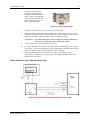
Wiring Schematic without Blackout Screen Box
Figure 28 Power Cable Routing without Blackout Screen Box
E-EQ-VX8OGWW-A
VX8 User’s Guide
36
Connect Power Cable
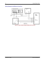
Wiring Schematic with Blackout Screen Box
Figure 29 Power Cable Routing with Blackout Screen Box
VX8 User’s Guide
E-EQ-VX8OGWW-A
Strain Relief Cable Clamps
37
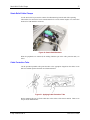
Strain Relief Cable Clamps
Use the strain relief to prevent the contacts from disconnecting from the unit while operating.
The brackets for strain relief can be turned around to fit various contact lengths. Use strain relief
brackets for USB and PS/2 connectors.
Figure 30 Strain Relief Brackets
When all peripherals are connected, the cabling should be put in the cable protection tube, see
below.
Cable Protection Tube
Cut the provided openable cable protection tube to the appropriate length. Put the cables in one
half of it and then put the other half on as illustrated below.
Figure 31 Applying Cable Protection Tube
Before mounting the port lid, fit the cable tube in the sockets of the chassis and lid. Then secure
the port lid as detailed below.
E-EQ-VX8OGWW-A
VX8 User’s Guide
38
Securing Port Lid
Securing Port Lid
The screws used for the port lid should be alternately tightened to provide proper dust and moist
protection (IP65 requirement). There are eight (8) Torx 20 screws securing the port lid.
Figure 32 Mounting the Port Lid
Fasten the cable tube in the vehicle, without putting strain on the tube. Now the VX8 is ready to
be mounted in the vehicle.
VX8 User’s Guide
E-EQ-VX8OGWW-A
Operation
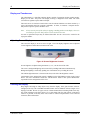
Powering On/Off
Connect the VX8 to a power source, either AC or Vehicle.
The power (on/off) switch is located on the front of the VX8. The switch is sealed by a rubber
membrane. The Status LED on the VX8 is illuminated when the power is on:
Press the power switch to start the VX8. You are now ready to use the computer.
Alternatively, the touchscreen can be configured so an extended touch on the touchscreen
provides a power on signal. Configuration of the touchscreen power on option is handled via the
VMT Manager option in the Control Panel. For more information consult the VX8 Reference
Guide or the system administrator responsible for the configuration of the VX8.
Enter data using the keyboard, touchscreen or a Serial Barcode Scanner.
Note:
Always turn the computer off prior to connecting or disconnecting any power source.
Figure 33 The VX8 Power Switch
The VX8 is designed for a controlled shutdown when using the power switch. A controlled
shutdown first closes any open programs, and then shuts down the Windows operating system.
DO NOT remove power from the VX8 without shutting down the VX8.
The VX8 shutdown may be initiated in any of the following ways:
•
Selecting the “Shut Down” option from the Windows Start Menu.
•
Selecting the “Shut Down” option from the Windows Task Manager. The Windows
Task Manager is displayed by pressing Ctrl-Alt-Del.
•
Momentarily pressing and releasing the power button. The VX8 behavior when the
power button is pressed can be configured in the Power Options section of the
Windows Control Panel.
•
An extended touch on the touchscreen can be configured to power down the VX8.
To enable this option, refer to the VMT Options section of the Windows Control
Panel. Once enabled, the extended touch behaves the same as a press of the power
switch.
•
Pressing and holding the power button for approximately five seconds. Any open
programs and the Windows operating system are shut down before power off. Use
this option to shut down the VX8 when the operating system is not responding.
For more information on the Windows shutdown process, please refer to the
Windows help function or commercially available Windows help guides.
E-EQ-VX8OGWW-A
VX8 User’s Guide
40
Powering On/Off
Reset Key Sequence (Reboot)
Note:
The <CTRL> + <ALT> + <DEL> function can be used to shut down a Microsoft
Windows application or reboot the computer. The keypress brings up the “Task
Manager” window.
To reboot the VX8 without turning the computer off, press
<CTRL> + <ALT> + <DEL>
and select Shut Down from the Task Manager window.
When the system is rebooted, Windows performs a controlled shutdown, closing any open
programs, before shutting down the Windows operating system. The current contents of RAM are
lost when rebooting. It is recommended to save any needed data and exit in an orderly fashion
from any running programs before rebooting.
VX8 User’s Guide
E-EQ-VX8OGWW-A
Keyboard Backlight
41
Keyboard Backlight
LXE VMT keyboards feature LEDs that illuminate the individual keys.
95 Key Keyboard
The backlight is manually controlled using the “backlight” key in the upper right hand corner of
the keyboard. Pressing the backlight key cycles the backlight through the levels of backlight
intensity:
•
Off
•
Maximum intensity
•
Medium intensity
•
Low intensity.
60 Key Keyboard
The keyboard backlight may be toggled manually by pressing <2nd> + <CTRL> + <F10>. This
key sequence immediately changes the state of the keyboard backlight as follows:
•
Turns the backlight Off if it is currently On.
•
Turns the backlight On if it is currently Off.
PS/2 Keyboard
Standard PS/2 keyboards generally do not feature keyboard backlighting.
E-EQ-VX8OGWW-A
VX8 User’s Guide
42
Display and Touchscreen
Display and Touchscreen
The VX8 Display is a thin-film transistor display capable of supporting SVGA graphics modes.
Display size is 800 x 600 pixels. The display covering is designed to resist stains. The touch
screen allows signature capture and touch input.
The touch screen is a Resistive Panel with a scratch resistant finish that can detect touches by a
stylus, and translate them into computer commands. In effect, it simulates a computer mouse.
Only Delrin or plastic styluses should be used.
Note:
Always use the point of the stylus for tapping or making strokes on the display. Never use
an actual pen, pencil or sharp object to write on the touch screen.
An extra or replacement stylus may be ordered from LXE. See the “Accessories” section for the
stylus part number.
Adjusting Screen Display
The color TFT display is an active source of light. The VX8 display brightness can be adjusted
via the brightness control buttons located on the VX8.
Figure 34 Screen Brightness Controls
Screen brightness is adjusted using the buttons (+) or (-) on the front of the VX8.
The screen’s background lighting can be turned off by holding both buttons simultaneously.
Background lighting is restored by pushing one of the buttons or by touching the screen
The ambient-light autosensor is located on the front, to the left of the brightness controls.
Configuration of the ambient light control is handled via the VMT Manager option in the Control
Panel. For more information consult the VX8 Reference Guide or the system administrator
responsible for the configuration of the VX8.
Cleaning the Display
Keep fingers and rough or sharp objects away from the display. If the glass becomes soiled or
smudged, clean only with a standard household cleaner such as Windex® without vinegar or use
Isopropyl Alcohol. Do not use paper towels or harsh-chemical-based cleaning fluids since they
may result in damage to the glass surface. Use a clean, damp, lint-free cloth. Do not scrub optical
surfaces. If possible, clean only those areas which are soiled. Lint/particulates can be removed
with clean, filtered canned air.
VX8 User’s Guide
E-EQ-VX8OGWW-A
Power Management
43
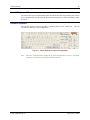
Calibrating the Touchscreen
Although the touch screen is installed and calibrated at the factory, users may make adjustments to
it by using the Fujitsu Touch Panel on the Microsoft Windows Programs menu. To calibrate the
touchscreen, select Start | Programs | UPDD | Calibrate.
The calibration utility displays a cross on the screen. Touch the center of the cross with the stylus
and hold for a few seconds. Release and repeat with the next cross. After all locations have been
touched, the calibration utility automatically closes.
If no input is received, the calibration utility times out. Press ESC to exit the calibration utility
without saving any changes,
Power Management
All Power Management is handled through the Microsoft Windows Control Panel. System
standby and turning the monitor and hard disk off are accessed from the Power Management icon.
For more information consult the VX8 Reference Guide or the system administrator responsible
for the configuration of the VX8.
Note:
E-EQ-VX8OGWW-A
When configuring power management, consider that the VX8 continues to draw power
from the vehicle battery when not in use. When power management is used, the drain on
battery power during periods of inactivity is minimal.
VX8 User’s Guide
44
Laser Barcode Scanner Warnings
Laser Barcode Scanner Warnings
•
Do not look into the laser’s lens.
•
Do not stare directly into the laser beam.
•
Do not remove the laser caution labels from the scanner.
•
Do not connect the laser barcode module to any other device.
Caution:
!
Please read the caution labels.
Avoid exposure. Laser light is emitted from the scanner’s aperture.
Use of controls, adjustments or performance of procedures other than those
specified herein may result in hazardous radiation exposure.
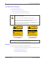
The scanner uses laser light. The following labels are representations of caution
and warning labels placed on laser scanners.
IEC 825-1
1993
1ST ED.
LASER LIGHT - DO NOT
STARE INTO BEAM
CLASS 2 LASER PRODUCT
IEC 825-1
1993
1ST ED.
1.0 mW - 675nm
LASER RADIATION
DO NOT STARE INTO BEAM OR
VIEW DIRECTLY WITH OPTICAL
INSTRUMENTS
CLASS 3A LASER PRODUCT
2.5 mW - 675nm
CAUTION
CAUTION
LASER RADIATION. DO NOT STARE
DO NOT STARE INTO BEAM
630-680nm LASER
1.0 MILLIWATT MAX OUTPUT
OPTICAL INSTRUMENTS.
675nm LASER
2.5 MILLIWATT MAX OUTPUT
CLASS II LASER PRODUCT
CLASS IIIA LASER PRODUCT
COMPLIES WITH 21 CFR 1040.10 1040.11 AND IEC825
COMPLIES WITH 21 CFR 1040.10 1040.11 AND IEC825
Figure 35 Caution Labels
Class II Scanner
Figure 36 Caution Labels
Class IIIA Scanner
Do not pour, spray, or spill any liquid on the scanner. The Barcode Scanner contains the
circuitry, scanning motor and laser. Handle with appropriate care.
Enter Data
You can enter data into the VX8 through several different methods:
VX8 User’s Guide
•
The tethered scanner connected to the COM1 serial port provides barcode data entry
•
The serial ports are used to input/output data
•
The keyboards provide manual entry
•
The touchscreen also provides manual entry
E-EQ-VX8OGWW-A
Enter Data
45
Keyboard Entry
Refer to “Appendix A Key Maps” for specific keypresses.
The keyboard is used to manually input data that is not collected otherwise. Almost any function
that a full sized computer keyboard can provide is duplicated on the LXE VMT keyboard but it
may take a few more keystrokes to accomplish a keyed task.
Almost every key has two or three different functions. The primary alpha or numeric character is
printed on the key.
For example, when the <2nd> key is selected pressing the desired second-function key produces
the <2nd> character i.e. <2nd> + F1 toggles the CAPS Lock function. The specific <2nd> character
is printed above the corresponding key.
Please refer to “Appendix A Key Maps” for instruction on the specific keypresses to access all
PC-compatible keyboard functions.
Touchscreen Entry
Note:
This section is directed to the VX8 user. The assumption is that the unit has been
configured and the touch panel calibrated by the System Administrator prior to releasing
the VX8 for use.
Note:
Always use the point of the stylus for tapping or making strokes on the display. Never use
an actual pen, pencil or sharp object to write on the touch screen.
The touchscreen input performs the same function as the mouse that is used to point to and click
elements on a desk top computer. The stylus is used in the same manner as a mouse – single tap or
double tap to select menu options, drag the stylus across text to select, hold the stylus down to
activate slider bars, etcetera.
Right click is generated by tapping the mouse icon in the system tray. After tapping, the mouse
icon highlights the right button of the icon in red. The next touchscreen tap is treated as a right
click. The mouse icon then returns to the left button highlighted in red so subsequent taps are
treated as left clicks.
When using a stylus, hold the stylus as if it were a pen or pencil. Touch an element on the screen
with the tip of the stylus then remove the stylus from the screen. The touch screen responds to an
actuation force (touch) of up to 4 oz. of pressure.
The touch screen can be used in conjunction with the keyboard and an input/output device
connected to one of the VX8’s serial ports.
E-EQ-VX8OGWW-A
•
Touch the stylus to the field of the data entry form to receive the next data feed.
•
The cursor begins to flash in the field.
•
The unit is ready to accept data from either the keyboard or a device connected to a
serial port.
VX8 User’s Guide
46
Enter Data
Scanner Entry
The following section is directed toward a generic tethered scanner connected to the COM1 serial
port on the VX8.
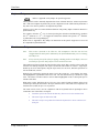
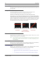
Aiming the Barcode Scanner
Aim the scanner away from you, direct it at the barcode and press the trigger to scan.
The Scan On LED (or equivalent) turns red to indicate the scanner is on.
Adjust the aim so that the thin, red laser beam covers the entire length of the barcode.
Some scanners use a laser aiming beam which then spreads into a wide beam when the scanner’s
Aiming Beam Timer expires. Place the aiming beam in the center of the barcode and hold the
scanner steady until the beam spreads and the barcode is decoded. Beeps may be heard as the
barcode is decoded. Refer to the barcode scanner user’s guide for information on the Aiming
Beam Timer and beep sequences, and the TE reference guide for host generated beep sequences.
The scan beam must cross every bar and space on the barcode.
Correct Scan
Incorrect Scan
Incorrect Scan
Figure 37 Scan Beam
Distance from Label
Large barcodes can be scanned at the maximum distance. Hold the scanner closer to small
barcodes (or with bars that are very close together).
Note:
Do not position the scanner exactly perpendicular to the barcode being scanned. In this
position, light can bounce back into the scanner’s exit window, and possibly prevent a
successful decode.
Successful Scan
When the scan is successful, the scanner’s good scan indicator illuminates, the scan on indicator is
off, and the currently running application may produce a distinctive audible tone.
Unsuccessful Scan
When the scan is unsuccessful, the scan on indicator remains illuminated and the currently
running application may produce distinctive audible tones. Check the following:
VX8 User’s Guide
•
Is the scanner programmed for the barcode being read?
•
Check the barcode for marks or physical damage e.g. ripped label, missing section,
etc.
•
Try scanning test symbols of the same code type at different distances and angles.
E-EQ-VX8OGWW-A
Appendix A Key Maps
95-key Keypad with Pointing Device
Esc
F1
~
F2
!
1
`
Caps
Lock
W
A
Z
Shift
Ctrl
$
%
4
5
E
S
R
D
X
F5
F4
#
3
@
2
Q
Tab
F3
C
H
I
J
N
0
O
K
M
Alt
<
,
+
=
:
;
>
.
}
]
"
'
?
/
Scroll
Lock
BackSpace
{
[
P
L
Print
Screen
SysRq
F12
_
-
)
9
U
F11
F10
(
8
Y
B
F9
*
7
G
V
F8
&
^
6
T
F
F7
F6
|
\
Enter
Shift
Alt
/
*
-
7
8
9
+
4
5
6
1
2
Home
0
Ins
L
Break
Num
Lock
End
Ctrl
Fn
Pause
PgUp
3
PgDn
.
Del
Enter
R
Figure 38 95-Key VMT QWERTY Keyboard
The key map table that follows lists the commands used for the VX8.
When running LXE’s RFTerm™ program, please refer to the RFTerm™ Reference Guide for
equivalent keys and keypress sequences:
Key Map 101-Key Equivalencies
There are ten hidden keys on the 95-key keyboard. Each of these hidden keys is accessed by
pressing the <Fn> key plus another key.
To get this key
Press These Keys and Then
Insert
Fn + 0 on the number pad
Home
Fn + 7 on the number pad
Page Up
Fn + 9 on the number pad
Delete
Fn + . on the number pad
End
Fn + 1 on the number pad
Page Down
Fn + 3 on the number pad
Note:
E-EQ-VX8OGWW-A
Up Arrow
Fn + 8 on the number pad
Left Arrow
Fn + 4 on the number pad
Down Arrow
Fn + 2 on the number pad
Right Arrow
Fn + 6 on the number pad
The 2nd key function is available on the 60-key keyboard only.
VX8 User’s Guide
48
60-key Standard Keypad
60-key Standard Keypad
ESC
2ND
CTRL
SHIFT
CAPS
BREAK
R/S
F1
F2
F3
@
!
|
ALT
E
;
\
A
SP
$
#
W
BKLT
F5
F4
%
R
:
D
F
G
Z
X
C
V
I
,
‘
S
(
*
U
Y
.
H
J
B
N
F8
F7
&
^
T
F6
_
~
INS
BKSP
P
PgUp
/
2nd
=
[
ENTER
L
Home
CAPS
F10
)
O
?
K
F9
PgDn
<
END
M
7
4
1
0
{
]
+
8
}
5
>
2
9
6
3
DEL
.
Figure 39 60-Key VMT QWERTY Keyboard
The key map table that follows lists the commands used for the VX8.
When running LXE’s RFTerm™ program, please refer to the RFTerm™ Reference Guide for
equivalent keys and keypress sequences:
Key Map 101-Key Equivalencies
When using a sequence of keys that includes the <2nd> key, press the <2nd> key first then the rest
of the key sequence.
Note:
NumLock can be toggled On or Off with the <2nd> <SHIFT> <F10> key sequence.
When the computer boots with a VMT keyboard, the default condition of Caps (or
CapsLock) is Off. The Caps (or CapsLock) condition can be set using BIOS Setup or
toggled with a <2nd>+<F1> key sequence. The CAPS LED on the VMT keyboard is
illuminated when CapsLock is On.
Press These Keys and Then
To get this key
nd
2
Keyboard Backlight
x
1
x
Suspend/Resume
nd
VX8 User’s Guide
Ctrl
x
Alt
Press this key
CapsLock
F10
F3
2nd
2
1
Shift
Shift
Shift
Alt
Alt
Ctrl
Ctrl
Esc
Esc
Space
Sp
Enter
Enter
Enter (numeric)
x
CapsLock (Toggle)
x
Enter
F1
Back Space
Ins/BkSp
Tab
Tab
The Suspend/Resume key has no function as Windows Power Management controls the power
management modes.
E-EQ-VX8OGWW-A
60-key Standard Keypad
49
To get this key
Press These Keys and Then
nd
2
BackTab
Ctrl-Break
Ctrl
Alt
x
2
Pause
2
Shift
Tab
x
x
Press this key
CapsLock
x
x
F2
F3
Up Arrow
Up Arrow
Down Arrow
Down Arrow
Right Arrow
Right Arrow
Left Arrow
Left Arrow
Insert
x
Ins/BkSp
Delete (numeric)
x
DEL
Home
x
Left Arrow
End
x
Right Arrow
Page Up
x
Up Arrow
Page Down
x
Right Shift
x
x
F7
Right Alt
x
x
F8
Right Ctrl
x
x
F9
Down Arrow
ScrollLock
x
x
F4
NumLock
x
x
F10
F1
F1
F2
F2
F3
F3
F4
F4
F5
F5
F6
F6
F7
F7
F8
F8
F9
F9
F10
F10
F11
x
x
F1
F12
x
x
F2
a
A
b
B
c
C
d
D
e
E
f
F
g
G
h
H
Press <Ctrl> then <2nd> then <F2> to produce Ctrl-Break.
E-EQ-VX8OGWW-A
VX8 User’s Guide
50
60-key Standard Keypad
To get this key
Press These Keys and Then
nd
2
Shift
Ctrl
Alt
Press this key
CapsLock
i
j
J
k
K
l
L
m
M
n
N
o
O
p
P
q
Q
r
R
s
S
t
T
u
U
v
V
w
W
x
X
y
Y
z
Z
A
VX8 User’s Guide
I
x
A
B
x
B
C
x
C
D
x
D
E
x
E
F
x
F
G
x
G
H
x
H
I
x
I
J
x
J
K
x
K
L
x
L
M
x
M
N
x
N
O
x
O
P
x
P
Q
x
Q
R
x
R
S
x
S
T
x
T
U
x
U
V
x
V
E-EQ-VX8OGWW-A
60-key Standard Keypad
51
To get this key
Press These Keys and Then
nd
2
Shift
Ctrl
Alt
Press this key
CapsLock
W
x
W
X
x
X
Y
x
Y
Z
x
Z
1 (alpha)
x
x
1
2 (alpha)
x
x
2
3 (alpha)
x
x
3
4 (alpha)
x
x
4
5 (alpha)
x
x
5
6 (alpha)
x
x
6
7 (alpha)
x
x
7
8 (alpha)
x
x
8
9 (alpha)
x
x
9
0 (alpha)
x
x
0
DOT (alpha)
x
K
1 (numeric)
1
2 (numeric)
2
3 (numeric)
3
4 (numeric)
4
5 (numeric)
5
6 (numeric)
6
7 (numeric)
7
8 (numeric)
8
9 (numeric)
9
0 (numeric)
0
DOT (numeric)
DOT
E-EQ-VX8OGWW-A
<
x
0
[
x
1
]
x
2
>
x
3
=
x
4
{
x
5
}
x
6
/ (numeric)
x
/ (alpha)
x
- (numeric)
x
- (alpha)
x
+ (numeric)
x
+ (alpha)
x
9
* (numeric)
x
I
x
7
7
x
8
8
x
9
VX8 User’s Guide
52
60-key Standard Keypad
To get this key
Press These Keys and Then
nd
2
* (alpha)
VX8 User’s Guide
x
Shift
Ctrl
x
Alt
Press this key
CapsLock
I
: (colon)
x
D
; (semicolon)
x
F
?
x
L
`
x
N
_ (underscore)
x
M
, (comma)
x
J
‘ (apostrophe)
x
H
~ (tilde)
x
B
\
x
S
|
x
A
“
x
G
!
x
Q
@
x
W
#
x
E
$
x
R
%
x
T
^
x
Y
&
x
U
(
x
O
)
x
P
E-EQ-VX8OGWW-A
Appendix B Regulatory Notices and Safety Information
FCC Information:
This device complies with FCC Rules, part 15. Operation is subject to the following conditions:
1.
This device may not cause harmful interference
and
2.
This device must accept any interference that may be received, including interference that may cause
undesired operation.
Note: This equipment has been tested and found to comply with the limits for a Class A digital device, pursuant
to part 15 of the FCC rules. These limits are designed to provide reasonable protection against harmful
interference when the equipment is operated in a commercial environment. This equipment generates, uses, and
can radiate radio frequency energy and, if not installed and used in accordance with the instruction manual, may
cause harmful interference to radio communications. Operation of this equipment in a residential area is likely to
cause harmful interference in which case the user will be required to correct the interference at his own expense.
Warning: Changes or modifications to this device not expressly approved by LXE, Inc., could void the user’s
authority to operate this equipment.
EMC Directive Requirements:
This is a Class A product. In a domestic environment this product may cause radio interference in which case the
user may be required to take adequate measures.
Industry Canada:
This Class A digital apparatus meets all requirements of the Canadian Interference Causing Equipment
Regulations. Operation is subject to the following two conditions: (1) this device may not cause harmful
interference, and (2) this device must accept any interference received, including interference that may cause
undesired operation.
Cet appareil numérique de la classe A respecte toutes les exigences du Règlement sur le matériel brouilleur du
Canada. Le présent appareil numérique n’émet pas de bruits radioélectriques dépassant les limites applicables aux
appareils numériques de Classe A prescrites dans le Règlement sur le brouillage radioélectrique édits par le
ministère des Communications du Canada.
RF Safety Notice:
Caution:
This device is intended to transmit RF energy. For protection against RF exposure to humans and in
accordance with FCC rules and Industry Canada rules, this transmitter should be installed such that
a minimum separation distance of at least 20 cm (7.8 in.) is maintained between the antenna and the
general population. This device is not to be co-located with other transmitters.
Important: This symbol is placed on the product to remind users to dispose of Waste Electrical
and Electronic Equipment (WEEE) appropriately, per Directive 2002-96-EC. In most areas,
this product can be recycled, reclaimed and re-used when properly discarded. Do not discard
labeled units with trash. For information about proper disposal, contact LXE through your
local sales representative, or visit www.lxe.com.
E-EQ-VX8OGWW-A
VX8 User’s Guide
54
Regulatory Notices
The product complies with the harmonized European standards and technical specifications listed below:
EN 61000-6-4:2001
EN 61000-6-2:2005
FCC part 15 Subpart B
Additionally all models are CB certified and comply with the standard below.
st
IEC 60950-1:2001 (1 Edition)
EN 61000-6-2:2001
Incl.: Group-and national differences for the CENELEC countries and national differences for US and Canada
according to CB Bulletin 109A / USCA 05 I.
VX8 User’s Guide
E-EQ-VX8OGWW-A
Regulatory Notices
!
55
Lithium Battery Safety Statement
!
Caution:
Lithium battery inside. Danger of explosion if battery is incorrectly replaced. Replace only with same or equivalent
type recommended by battery manufacturer. (US)
Attention:
Contient une pile de lithium. Risque d’explosion dans le cas où la pile ne serait pas correctement remplacée.
Remplacer uniquement avec une pile semblable ou equivalente au type de pile recommandé par le fabricant. (FR)
Forsigtig:
Indeholder lithiumbattterier. Risiko for eksplosion, hvis batteriet udskiftes forkert. Må kun udskiftes med samme
eller tilsvarende type, som anbefalet af fabikanten. (DK)
Varoitus:
Tämä tuote käyttää laservaloa. Skannerissa on jokin seuraavista tarroista. Lue Huomio-kohta. (FI)
Vorsicht:
Enthält Lithium-Batterie. Bei unsachgemäßem Ersatz besteht Explosionsgefahr. Nur durch gleichen oder vom
Hersteller empfohlenen Typ ersetzen. (DE)
Attenzione:
Batteria al litio. Pericolo di esplosione qualora la batteria venga sostituita in maniera scorretta. Sostituire solo con lo
stesso tipo o equivalente consigliato per il fabbricante. (IT)
Atenção:
Contém pilha de lítio. Há perigo de explosão no caso de uma substituição incorreta. Substitua somente pelo mesmo
tipo, ou equivalente, recomendado pelo fabricante. (PT)
Varning:
Innehåller litiumbatteri. Fara för explosion om batteriet är felaktigt placerat eller av fel typ. Använd endast samma
eller motsvarande typ batterier rekommenderade av tillverkaren. (SE)
Advarsel:
Innmontert Lithium batteri. Eksplosjonsfare ved feil montering av batteri. Benytt kun batteri anbefalt av produsent.
(NO)
Cuidado:
Pila de litio adentro. Peligro de explosión si la pila se reemplaza incorrectamente. Reemplace solamente con el
mismo tipo o equivalente recomendado por el fabricante. (ES)
Oppassen:
Bevat Lithium-batterij. Incorrrecte plaatsing van batterij kan leiden tot explosiegevaar. Alleen vervangen door
hetzelfde of door fabrikant aanbevolen gelijkwaardig type. (NL)
E-EQ-VX8OGWW-A
VX8 User’s Guide
56
Regulatory Notices
Lithium Battery Safety Statement
!
!
(KR)
(GR)
(CN)
(JP)
Dikkat:
(TR)
Legend:
Chinese
Danish
Dutch
English
Finnish
French
German
Greek
VX8 User’s Guide
CN
DK
NL
US
FI
FR
DE
GR
Italian
Japanese
Korean
Norwegian
Portuguese
Spanish
Swedish
Turkish
IT
JP
KR
NO
PT
ES
SE
TR
E-EQ-VX8OGWW-A
Regulatory Notices
57
Français Avertissement et emarque
Le manuel n'explique pas comment installer et utiliser le système d'exploitation ou les applications.
Avertissement !
Vous avertit des risques de dommages pour les individus ou les biens. Suivez toujours les
instructions qui figurent en regard de ce symbole.
Remarque !
Attire votre attention sur les problèmes qui peuvent survenir si une mesure n'est pas prise ou est
prise de manière incorrecte.
Soyez toujours prudent lorsque vous travaillez avec l'électricité.
Ne mettez jamais l'ordinateur sous tension si les conditions environnementales ne sont pas dans les
limites indiquées (cf. Annexe I, Spécifications). Par exemple, vérifiez que l'ordinateur est mis sous
tension avant d'entrer dans une unité de stockage froide.
Avant l'installation, veillez à ce que tous les critères relatifs à l'environnement soient respectés.
Vous trouverez une liste de ces critères en Annexe I, dans les Spécifications.
Ne changez pas les vis d'origine avec lesquelles sont montés les supports. Des vis trop longues
peuvent endommager le système électrique de l'ordinateur.
Soyez toujours prudent lorsque vous travaillez avec l'électricité.
Si la masse du véhicule n'est pas la même que celle du châssis du véhicule, vous devez alors monter
l'ordinateur sur des patins en caoutchouc.
Ne connectez jamais l'alimentation aux prises 5 ou 6, qui servent à la fonction de noir de l'écran
décrite à la section .2.2.
Vous pouvez définir cette fonction dans l'application VMT Computer Manager ; cf. 4.3.1.
Seuls les salariés (IT) expérimentés sont autorisés à utiliser le logiciel VMT Computer Manager car
des paramètres incorrects peuvent avoir des effets indésirables sur certaines fonctions.
Si vous modifiez ou réinstallez le système d'exploitation de l'ordinateur, vous pouvez être amené à
réinstaller les pilotes pré-installés.
Une fois que les périphériques sont connectés, fixez les câbles sur la partie inférieure de l'ordinateur
qui comporte des trous prévus pour les brides de câbles.
N'oubliez pas que les systèmes d'exploitation n'ont pas tous une prise en charge intégrée de la souris
(par exemple, DOS).
E-EQ-VX8OGWW-A
VX8 User’s Guide
58
VX8 User’s Guide
Regulatory Notices
E-EQ-VX8OGWW-A
Index
A
F
Aim Barcode Scanner..............................................49
Features .....................................................................1
Flash Memory............................................................1
B
Barcode Scanner......................................................29
Barcode scanner data entry......................................48
Beam, Long Range Scanner ....................................49
Bottom Mounting Bracket .......................................21
Bracket
How To ...............................................................21
C
CAPS LOCK Mode LED Indicator.........................11
Caps-Lock Mode .....................................................12
Cleaning
Display ................................................................45
Connection
COM1 .................................................................29
Contrast Up and Down
Not applicable .....................................................13
Control Keys, location.............................................13
Control Panel, Windows............................................6
CPU ...........................................................................1
CTRL+ALT+DEL...................................................43
D
Data entry, How To .................................................47
Defaults
Caps Lock ...........................................................12
Display.......................................................................6
Cleaning ..............................................................45
Features...............................................................45
Pixels...............................................................6, 45
Power Management ............................................46
Display Brightness Control Keys ............................13
Display Contrast Control Keys................................13
Document Conventions .............................................2
E
Enter Data, How To.................................................47
Environmental Specifications....................................2
E-EQ-VX8OGWW-A
G
Getting Started...........................................................3
Good Scan LED.......................................................29
H
Hard disk
Power Management ............................................46
Hidden Keys ........................................................8, 10
How To
AC/DC Power Connection..................................33
Aim the Scan Beam.............................................49
Connect Barcode Scanner ...................................29
Initiate Page Up command..................................12
Keyboard data entry............................................48
Toggle 2nd key on and off ..................................12
Toggle Caps-Lock on and off .............................12
Type <!> .............................................................12
I
IEC IP56 ....................................................................2
Install
External Speakers................................................32
Scanner................................................................29
K
Key functions
Unused ................................................................11
Key Map ............................................................51, 52
Key Maps
Hidden Keys ...................................................8, 10
Keyboard
Control Keys .......................................................13
Hidden Key Functions ....................................8, 10
LED Indicators....................................................11
Keyboard Backlight.......................................9, 11, 13
Keypress Sequence .............................................44
Toggling Manually..............................................44
VX8 User’s Guide
60
Keyboard data entry ................................................48
keyboard shortcuts...................................................14
L
Laser Aperture .........................................................29
Laser barcode scanner warnings..............................47
LED indicators.........................................................11
LEDs
2nd ......................................................................12
Caps-Lock, CAPS ...............................................12
Secondary Keys ..................................................12
M
Manuals ...................................................................17
N
Nine-pin D-shell female connector
and the Scanner ...................................................29
NUM LOCK
and 2nd Functions ................................................11
Disabled ..............................................................11
Index
S
Scanner
Nine-pin D-shell female connector .....................29
Scanner data entry ...................................................48
Scanner Installation .................................................29
Scanning distance ....................................................49
Secondary Mode LED Indicator..............................11
Shielded Cable Requirement ...................................29
Speaker Volume Control Keys ................................13
Specifications
Environmental.......................................................2
Standby Mode
Power Management ............................................46
Status LED Indicator ...............................................11
Stylus .................................................................45, 48
Stylus Data Entry.....................................................48
Successful Scan indicators ......................................49
SVGA graphics modes ..............................................6
System Tray icons, Windows ....................................6
T
On/Off condition of CapsLock................................52
On/Off condition of NumLock ................................52
On/Off Switch .........................................................41
Operating Temperature..............................................2
Terminal Emulator List .............................................1
Thin Film Transistor (TFT) Display..........................6
Toggle 2nd key on and off ......................................12
Touch Screen .....................................................45, 48
Touchscreen
Calibration ..........................................................46
Data Entry ...........................................................48
Finger or Stylus...................................................48
Trigger .....................................................................29
P
U
Pen Stylus ..........................................................45, 48
Power Management
Windows .............................................................46
Power Switch...........................................................41
Procedure
Mounting Brackets..............................................21
Uninterruptible Power Supply Battery ....................16
Unsuccessful Scan indicators ..................................49
Unused key functions ..............................................11
UPS Battery Pack ....................................................16
Q
Vehicle Power
12V to 60V DC ...................................................16
View
Display ................................................................45
VX8 Reference Guide ...............................................1
O
Quick Start Instructions.............................................3
R
Rebooting the VX8..................................................43
Reset ........................................................................43
V
W
Warm Boot ..............................................................43
Warning
Laser light ...........................................................47
VX8 User’s Guide
E-EQ-VX8OGWW-A
Index
Windows
Closing a Window ..............................................43
Control Panel ........................................................6
Help Screens .........................................................6
E-EQ-VX8OGWW-A
61
Power Management ............................................46
System Tray icons.................................................6
Windows online Help ................................................6
VX8 User’s Guide
62
VX8 User’s Guide
Index
E-EQ-VX8OGWW-A