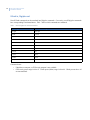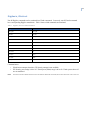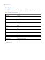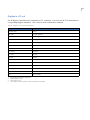
1
KTD-313 Data Converter
Installation Manual
Copyright
Disclaimer
Trademarks and patents
Copyright © 2006, GE Security Inc. All rights reserved.
This document may not be copied or otherwise reproduced, in whole or in part, except as specifically
permitted under US and international copyright law, without the prior written consent from GE.
Document number/ 1037145D (May 2006).
THE INFORMATION IN THIS DOCUMENT IS SUBJECT TO CHANGE WITHOUT NOTICE. GE ASSUMES NO
RESPONSIBILITY FOR INACCURACIES OR OMISSIONS AND SPECIFICALLY DISCLAIMS ANY LIABILITIES, LOSSES,
OR RISKS, PERSONAL OR OTHERWISE, INCURRED AS A CONSEQUENCE, DIRECTLY OR INDIRECTLY, OF THE USE
OR APPLICATION OF ANY OF THE CONTENTS OF THIS DOCUMENT. FOR THE LATEST DOCUMENTATION,
CONTACT YOUR LOCAL SUPPLIER OR VISIT US ONLINE AT WWW.GESECURITY.COM.
This publication may contain examples of screen captures and reports used in daily operations. Examples
may include fictitious names of individuals and companies. Any similarity to names and addresses of
actual businesses or persons is entirely coincidental.
GE and the GE monogram are registered trademarks of General Electric.
Other trade names used in this document may be trademarks or registered trademarks of the manufacturers or vendors of the respective products.
Intended use
Use this product only for the purpose it was designed for; refer to the data sheet and user documentation.
For the latest product information, contact your local supplier or visit us online at www.gesecurity.com.
FCC compliance
This equipment has been tested and found to comply with the limits for a Class A digital device, pursuant to
part 15 of the FCC Rules. These limits are designed to provide reasonable protection against harmful interference when the equipment is operated in a commercial environment. This equipment generates, uses,
and can radiate radio frequency energy and, if not installed and used in accordance with the instruction
manual, may cause harmful interference to radio communications.
You are cautioned that any changes or modifications not expressly approved by the party responsible for
compliance could void the user's authority to operate the equipment.
1
Contents
Preface . . . . . . . . . . . . . . . . . . . . . . . . . . . . . . . . . . . . . . . . . . . . . . . . . . . . . . . . . . . . . . . . . . . . . . . . . . . . . 1
Conventions used in this document. . . . . . . . . . . . . . . . . . . . . . . . . . . . . . . . . . . . . . . . . . . . . . . . . . . . . . . . . . . . . . . . . . . . . . . .1
Safety terms and symbols . . . . . . . . . . . . . . . . . . . . . . . . . . . . . . . . . . . . . . . . . . . . . . . . . . . . . . . . . . . . . . . . . . . . . . . . . . . . . . . .1
Product overview . . . . . . . . . . . . . . . . . . . . . . . . . . . . . . . . . . . . . . . . . . . . . . . . . . . . . . . . . . . . . . . . . . . . 2
Installation . . . . . . . . . . . . . . . . . . . . . . . . . . . . . . . . . . . . . . . . . . . . . . . . . . . . . . . . . . . . . . . . . . . . . . . . . 3
Mounting the unit. . . . . . . . . . . . . . . . . . . . . . . . . . . . . . . . . . . . . . . . . . . . . . . . . . . . . . . . . . . . . . . . . . . . . . . . . . . . . . . . . . . . . . . . .3
Wiring and DIP switches. . . . . . . . . . . . . . . . . . . . . . . . . . . . . . . . . . . . . . . . . . . . . . . . . . . . . . . . . . . . . . 4
Wiring connections . . . . . . . . . . . . . . . . . . . . . . . . . . . . . . . . . . . . . . . . . . . . . . . . . . . . . . . . . . . . . . . . . . . . . . . . . . . . . . . . . . . . . . .5
DIP switch settings . . . . . . . . . . . . . . . . . . . . . . . . . . . . . . . . . . . . . . . . . . . . . . . . . . . . . . . . . . . . . . . . . . . . . . . . . . . . . . . . . . . . . . .6
Connections for AD Manchester in, Digiplex out . . . . . . . . . . . . . . . . . . . . . . . . . . . . . . . . . . . . . . . . . . . . . . . . . . . . . . . . . . . .7
Connections for Digiplex in, AD Manchester out . . . . . . . . . . . . . . . . . . . . . . . . . . . . . . . . . . . . . . . . . . . . . . . . . . . . . . . . . . . .9
Operating the unit . . . . . . . . . . . . . . . . . . . . . . . . . . . . . . . . . . . . . . . . . . . . . . . . . . . . . . . . . . . . . . . . . . 10
AD Manchester in, Digiplex out . . . . . . . . . . . . . . . . . . . . . . . . . . . . . . . . . . . . . . . . . . . . . . . . . . . . . . . . . . . . . . . . . . . . . . . . . . 10
Digiplex in, AD Manchester out . . . . . . . . . . . . . . . . . . . . . . . . . . . . . . . . . . . . . . . . . . . . . . . . . . . . . . . . . . . . . . . . . . . . . . . . . . 11
Ultrak in, Digiplex out . . . . . . . . . . . . . . . . . . . . . . . . . . . . . . . . . . . . . . . . . . . . . . . . . . . . . . . . . . . . . . . . . . . . . . . . . . . . . . . . . . . 12
Digiplex in, Ultrak out . . . . . . . . . . . . . . . . . . . . . . . . . . . . . . . . . . . . . . . . . . . . . . . . . . . . . . . . . . . . . . . . . . . . . . . . . . . . . . . . . . . 13
VCL in, Digiplex out . . . . . . . . . . . . . . . . . . . . . . . . . . . . . . . . . . . . . . . . . . . . . . . . . . . . . . . . . . . . . . . . . . . . . . . . . . . . . . . . . . . . . 14
Digiplex in, VCL out . . . . . . . . . . . . . . . . . . . . . . . . . . . . . . . . . . . . . . . . . . . . . . . . . . . . . . . . . . . . . . . . . . . . . . . . . . . . . . . . . . . . . 15
Pelco-D/P in, Digiplex out . . . . . . . . . . . . . . . . . . . . . . . . . . . . . . . . . . . . . . . . . . . . . . . . . . . . . . . . . . . . . . . . . . . . . . . . . . . . . . . 16
Digiplex in, Pelco-D/P out . . . . . . . . . . . . . . . . . . . . . . . . . . . . . . . . . . . . . . . . . . . . . . . . . . . . . . . . . . . . . . . . . . . . . . . . . . . . . . . 17
Contacting technical support . . . . . . . . . . . . . . . . . . . . . . . . . . . . . . . . . . . . . . . . . . . . . . . . . . . . . . . . 18
Online publication library . . . . . . . . . . . . . . . . . . . . . . . . . . . . . . . . . . . . . . . . . . . . . . . . . . . . . . . . . . . . . . . . . . . . . . . . . . . . . . . 18
2
KTD-313 Data Converter
Installation Manual
1
Preface
This is the GE KTD-313 Data Converter Installation Manual. This document includes an overview of the
product and detailed instructions explaining:
•
•
•
how to install and wire the KTD-313;
how to configure the KTD-313 to work with various third-party hardware; and
how to operate the KTD-313.
There is also information describing how to contact technical support if you have questions or concerns.
To use this document effectively, you should have the following minimum qualifications:
•
•
a basic knowledge of CCTV systems and components; and
a basic knowledge of electrical wiring and low-voltage electrical connections.
Read these instructions and all ancillary documentation entirely before installing or operating this product.
The most current versions of this and related documentation may be found on our website. Refer to Online
publication library on page 18 for instructions on accessing our online publication library.
Note:
A qualified service person, complying with all applicable codes, should perform all required hardware installation.
Conventions used in this document
The following conventions are used in this document:
Bold
Menu items and buttons.
Italic
Emphasis of an instruction or point; special terms.
File names, path names, windows, panes, tabs, fields, variables, and other GUI elements.
Titles of books and various documents.
Blue italic
(Electronic version.) Hyperlinks to cross-references, related topics, and URL addresses.
Monospace
Text that displays on the computer screen.
Programming or coding sequences.
Safety terms and symbols
These terms may appear in this manual:
CAUTION: Cautions identify conditions or practices that may result in damage to the equipment or other property.
WARNING: Warnings identify conditions or practices that could result in equipment damage or serious personal injury.
2
KTD-313 Data Converter
Installation Manual
Product overview
The following translators are programmed into the KTD-313:
AD Manchester in, Digiplex out. Receives American Dynamics (AD) Manchester protocol and converts
it to Digiplex RS-422. This enables an AD Manchester system to control up to 64 GE Security PTZ
receivers on a single twisted-pair cable. In addition, it enables preset control of GE Security receivers and
variable-speed control of the CyberDome® when used with variable speed joystick controllers.
Digiplex in, AD Manchester out. RS-422 commands and converts them to AD Manchester protocol,
which enables up to 512 AD Manchester receivers or domes to be controlled by at least one GE Security
keypad.
Ultrak in, Digiplex out. Receives commands from Ultrak controllers and converts them to Digiplex RS422. This enables an Ultrak system to control up to 250 GE Security PTZ receivers on a single twisted-pair
cable. It also allows preset control of GE Security receivers and variable-speed control of the CyberDome
when used with variable speed joystick controllers.
Digiplex in, Ultrak out. Receives Digiplex RS-422 commands and converts them to an Ultrak protocol,
which enables up to 250 Ultrak receivers or domes to be controlled by at least one GE Security keypad.
VCL in, Digiplex out. Receives commands from VCL controllers and converts them to Digiplex RS-422.
This enables a VCL system to control up to 128 GE Security PTZ receivers.
Digiplex in, VCL out. Receives Digiplex RS-422 commands and converts them to VCL protocol, which
enables up to 128 VCL receivers or domes to be controlled by one or more GE Security keypads.
Pelco-D/P in, Digiplex out. Receives commands from Pelco-D/P controllers and converts them to
Digiplex RS-422. This enables a Pelco-D system to control up to 254 GE Security PTZ receivers and a
Pelco-P system to control up to 64 GE Security PTZ receivers.
Digiplex in, Pelco-D/P out. Receives Digiplex RS-422 commands and converts them to Pelco-D/P
protocol, which enables up to 254 Pelco-D (and 64 Pelco-P) receivers or domes to be controlled by one or
more GE Security keypads.
3
Installation
The KTD-313 must be between the unit generating the commands and the PTZ receivers. Each signal line
coming from the unit generating the commands must include a KTD-313. Figure 1 shows a sample system
configuration.
Figure 1. Placing the unit in a system (American Dynamics)
ON
1 2 3 4 5 6 7 8
KTD-313s to GE Security PTZ receivers
Code distributor
ON
1 2 3 4 5 6 7 8
ON
1 2 3 4 5 6 7 8
Third-party CPU
ON
1 2 3 4 5 6 7 8
Keypad
ZONE 32
PARKING GARAGE
CAMERA 22
MONITOR 2
mon
1
4
A
D
1ST
auto
focus
view
zone
dsr/vcr
aux 1
aux 2
aux 3
aux 4
2
3
seq
alarm
tour
store
find
5
7
8
esc
0
B
E
C
GE Security PTZ receivers (up to 64)
6
+
zoom
-
9
+
focus
-
+
iris
-
CAUTION: Complete all installation and configuration steps before supplying power to the unit.
Mounting the unit
Mount the unit using the mounting slots (Figure 2) and appropriate fasteners (not provided).
Figure 2. KTD-313 mounting slots
Mounting slot
Mounting slot
ON
1 2 3 4 5 6 7 8
4
KTD-313 Data Converter
Installation Manual
Wiring and DIP switches
This section explains the connections and DIP switch settings you will need to make to use your KTD-313 with
third-party vendors’ equipment. Because there are special considerations for AD Manchester equipment, see
Connections for AD Manchester in, Digiplex out on page 7 and Connections for Digiplex in, AD Manchester
out on page 9 for details not covered in this section.
For all connections, observe polarity when connecting the digital cables.
Figure 3 shows a close-up of the KTD-313’s terminal block and DIP switch block. You will need to connect
different wires to these six terminals and set the eight DIP switches appropriately to match the third-party
hardware in your system.
Figure 3. Terminal block and DIP switches
Mounting slot
Mounting slot
ON
1 2 3 4 5 6 7 8
Terminal block
DIP switches
ON
1
2
3
4
5
6
1 2 3 4 5 6 7 8
ON for input termination
OFF for input loopthrough
12 VDC power supply
See Table 1 on page 5
See Table 1 on page 5
See Table 2 on page 6
See Table 2 on page 6
Refer to Table 1 on page 5 and Table 2 on page 6 to determine how to wire and configure your KTD-313 for
AD Manchester, Pelco, Ultrak, and VCL equipment. For special exceptions, see the appropriate sections that
follow.
5
Wiring connections
Table 1 shows how to wire the KTD-313 for various third-party vendors’ equipment.
For example, on a Digiplex in, Ultrak out setup: connect 12 VDC power to terminals 1 and 2; connect wires A
and B to terminals 3 and 4 respectively; and connect d+ and d- to terminals 5 and 6 respectively.
Table 1.
Wire connections
Terminals 3 – 4
Terminals 5 – 6
Terminals 1 – 2
Wires
Description
Wires
Description
AD Manchester in;
Digiplex out
12 VDC power
W, B
AD Manchester serial in
A, B
RS-422 out (Digiplex protocol)
Digiplex in;
AD Manchester out
12 VDC power
A, B
RS-422 in (Digiplex protocol
Digiplex loopthrough)
W, B
Serial out (AD Manchester
protocol)
Pelco-D/P in;
Digiplex out
12 VDC power
tx+, tx-
Digital in (Pelco-D/P protocol)
A, B
Digital out (Digiplex protocol)
Digiplex in;
Pelco-D/P out
12 VDC power
A, B
RS-422 in (Digiplex protocol)
d+, d-
Digital out (Pelco-D/P protocol)
Ultrak in;
Digiplex out
12 VDC power
tx+, tx-
Digital in (Ultrak protocol)
A, B
Digital out (Digiplex protocol
Digiplex in;
Ultrak out
12 VDC power
A, B
RS-422 in (Digiplex protocol)
d+, d-
Digital out (Ultrak protocol)
VCL in;
Digiplex out
12 VDC power
tx+, tx-
Digital in (VCL protocol)
A, B
Digital out (Digiplex protocol)
Digiplex in;
VCL out
12 VDC power
A, B
RS-422 in (Digiplex protocol)
d+, d-
Digital out (VCL protocol)
1.
W, B, S1 AD Manchester serial out
See Connections for AD Manchester in, Digiplex out on page 7 for specifics on wiring the KTD-313 for AD Manchester serial out.
6
KTD-313 Data Converter
Installation Manual
DIP switch settings
The DIP switches form groups. Switches 1, 2, and 3 determine the Digiplex setup; switches 4, 5, and 6
determine special features for the selected setup; and switches 7 and 8 set the KTD-313 to loopthrough or
termination. To read the values in the table, 0 equals OFF (down position), and 1 equals ON (up position).
Table 2.
DIP switch settings per third-party vendor
Switches 1 – 3 Switch 4
AD Manchester in;
Digiplex out
000
Switches 5 – 6
0: Maximum joystick deflection
No settable features.
produces maximum dome speed.
Switches 7 – 8
00: Input loopthrough
11: Input termination
1: Maximum joystick deflection
produces 50% dome speed.
See Connections for
AD Manchester in, Digiplex out on
page 7 for details.
Digiplex in;
AD Manchester out
000
Allows you to increase AD Manchester address site range
from 64 to 512. See Connections for Digiplex in,
AD Manchester out on page 9 for specific DIP switch
settings.
00: Input loopthrough
11: Input termination
Pelco- D/P in;
Digiplex out
111
0: Pelco-D protocol
1: Pelco-P protocol
00: 9600 baud
01: 4800 baud
11: 2400 baud
00: Input loopthrough
11: Input termination
Digiplex in;
Pelco- D/P out
011
0: Pelco-D protocol
1: Pelco-P protocol
00: 9600 baud
01: 4800 baud
11: 2400 baud
00: Input loopthrough
11: Input termination
Ultrak in;
Digiplex out
010
No settable features.
Digiplex in;
Ultrak out
110
VCL in;
Digiplex out
111
No settable features.
00: Input loopthrough
11: Input termination
Digiplex in;
VCL out
110
No settable features.
00: Input loopthrough
11: Input termination
Note:
The address range of Ultrak controllers is 1
through 250. Digiplex addresses outside this
range are not accessible.
No settable features.
Note:
The address range of Ultrak receivers is 1 through
250. Site addresses outside this range are not
translated.
00: Input loopthrough
11: Input termination
00: Input loopthrough
11: Input termination
For example, on a Digiplex in, Ultrak out setup: set DIP switches 1, 2, and 3 to 110 (ON-ON-OFF); leave
switches 4, 5, and 6 to OFF (there are no settable features for this setup, so it doesn’t matter what these are set
to anyway); and set switches 7 and 8 to 00 (OFF-OFF) for loopthrough or 11 (ON-ON) for termination.
Note:
For all connections, set the termination DIP switches (7 and 8) to OFF for every KTD-313 unless it is at the end of a digital
line, in which case you should set them both to ON.
7
Connections for AD Manchester in, Digiplex out
This section details wiring and addressing issues involved with an AD Manchester in, Digiplex out setup.
Maximum pan speed
This translator uses DIP switch 4 to control maximum pan speed. This feature is important when you use
variable-speed domes as receivers because full joystick deflection is associated with maximum dome speed.
Set DIP switch position 4 as follows:
•
•
OFF: Maximum joystick deflection produces 100% dome speed. (Use with AD Manchester joystick
keypads.)
ON: Maximum joystick deflection produces 50% dome speed. (Use with fixed-speed AD Manchester
keypads.)
If there are no variable-speed dome receivers, DIP switch 4 will have no effect.
Wiring
AD Manchester recommends a shielded twisted-pair cable with its system and provides three connections at
each of its devices (W, B, shield). If the KTD-313 is the last device in a daisy chain, leave the shield lead
disconnected. If connecting to more AD Manchester devices, connect the shield lead of the incoming wire to
the shield lead of the outgoing wire (Figure 4).
Figure 4. AD Manchester in, Digiplex out
ON
12 VDC power supply
1
2
3
4
W B
5
A
S
AD Manchester serial in
6
1 2 3 4 5 6 7 8
B
ON for input termination
OFF for input loopthrough
Maximum pan speed
W
B
AD Manchester in; Digiplex out (1, 2, and 3 OFF)
AD Manchester serial out
RS-422 out (Digiplex protocol)
For daisy-chained AD Manchester devices, connect the outgoing wires in parallel.
8
KTD-313 Data Converter
Installation Manual
Site addressing
The following issues exist when installing a KTD-313 and Digiplex receivers in an AD Manchester system:
•
•
•
•
•
•
Table 3.
An AD Manchester CPU typically has four output ports (group outputs) for its PTZ receiver control.
Each group output from the CPU is responsible for a range of PTZ receivers.
Group 1 addresses sites 1 through 64; Group 2, 65 – 128; Group 3, 129 – 192; Group 4, 193 – 256.
An AD Manchester CPU can control at least 256 PTZ receivers; however, the address transmitted to
the receiver in any one group is always in the range of 1 to 64. (A typical AD Manchester CPU will
not transmit a number higher than 64.)
Digiplex receivers’ site addresses range from 0 to 511.
The Digiplex receiver must have an address number from 1 to 64, even if its site number is higher than
64. For example, receiver site number 66 will have a Digiplex address of 2 (66 - 64 = 2); site number
256 will have a Digiplex address of 64 (256 - 192 = 64). See Table 3.
Addressing Digiplex receivers in an AD Manchester system
AD Manchester control output AD Manchester site number
Minus this number
Equals the Digiplex address
Group 1
1 – 64
0
1 – 64
Group 2
65 – 128
64
1 – 64
Group 3
129 – 192
128
1 – 64
Group 4
193 – 256
192
1 – 64
For example, when receiver site number 68 is called up from the CPU, the signal is sent through group output
2 to a receiver addressed as number 4 (68 - 64 = 4).
Figure 5. AD Manchester CPU addressing Digiplex receivers
KTD-313
Group 1: ADM sites 1 to 64
ON
Group 2: ADM sites 65 to 128
1 2 3 4 5 6 7 8
Digiplex address 1 to 64
ON
Group 3: ADM sites 129 to 192
1 2 3 4 5 6 7 8
Digiplex address 1 to 64
ON
Group 4: ADM sites 193 to 256
1 2 3 4 5 6 7 8
Digiplex address 1 to 64
ON
1 2 3 4 5 6 7 8
Digiplex address 1 to 64
AD Manchester unit
Note:
Refer to AD Manchester system documentation for further addressing information.
9
Connections for Digiplex in, AD Manchester out
The address range of AD Manchester receivers is 1 through 64. GE Security keypads can address a range of 0
through 511. DIP switch positions 4 through 6 enable up to 512 AD Manchester receivers or domes to be
addressed by selecting the 64 address block to which the KTD-313 responds. (One KTD-313 is required for
each 64 address block.) When a GE Security keypad calls AD Manchester receiver site number 68, the signal
goes to the KTD-313 with the address block of 64 and to the AD Manchester receiver addressed as number 4
(64 + 4 = 68).
Figure 6. Digiplex in, AD Manchester out
ON
12 VDC power supply
1
2
3
A
4
B
5
W
6
1 2 3 4 5 6 7 8
B
ON for input termination
OFF for input loopthrough
RS-422 in (Digiplex protocol
A
No settable features
B
Digiplex in; AD Manchester out (1 ON; 2 and 3 OFF)
Digiplex loopthrough
Serial out (AD Manchester protocol)
Table 4 lists the address block DIP switch settings and AD Manchester address for each block.
Table 4.
DIP switch settings and receiver site numbers
Address
block
DIP switches
4–6
ADM site
address range
Receiver
number
0
000
1 – 64
1 – 64
64
100
1 – 64
128
010
192
110
Address
block
DIP switches
4–6
ADM site
address range
Receiver
number
256
001
1 – 64
257 –320
65 – 128
320
101
1 – 64
321 – 384
1 – 64
129 – 192
384
011
1 – 64
385 – 448
1 – 64
193 – 256
448
111
1 – 64
449 – 512
The following addressing issues exist when installing AD Manchester receivers in a Digiplex system:
•
•
•
You can give several KTD-313s the same address block numbers, but make sure there are no
duplicated addresses on the outputs of KTD-313s that share the same address block numbers. For
example, two KTD-313s share the address block of 0. The first has 32 AD Manchester receivers
connected to it, numbered 1 through 32. The second has 32 AD Manchester receivers connected to it,
numbered 33 through 64.
AD Manchester does not permit 0 as a valid address, but GE Security does. A selection of site 0 on a
Digiplex control device is rejected by the KTD-313.
GE Security and AD Manchester addresses are coded differently (AD Manchester sends “site = 0”
when address 1 is controlled). To maintain the same numbering for GE Security and AD Manchester
components, the addresses are automatically shifted by one. Therefore, one address at each end of the
address range is lost.
10
KTD-313 Data Converter
Installation Manual
Operating the unit
When you have finished installing the KTD-313 and all system components, apply power to the system. For
platform-specific operation, refer to the appropriate configuration in this section.
AD Manchester in, Digiplex out
When using GE Security receivers in an AD Manchester system, be aware of the following operating issues:
•
•
No GE Security menu-based programming operations are available from AD Manchester controllers.
AD Manchester controllers cannot control all CyberDome functions.
Table 5 shows compatible commands between AD Manchester controllers and Digiplex receivers.
(AD Manchester entries will vary according to controller type; two common entry options are presented.)
Table 5.
AD Manchester in, Digiplex out command translations
For this Digiplex result
Use this AD Manchester entry
Focus near
NEAR or FOCUS N
Focus far
FAR or FOCUS F
Iris open
OPEN or IRIS O
Iris close
CLOSE or IRIS C
Zoom in
TELE -or- ZOOM T
Zoom out
WIDE or ZOOM W
Autopan on
Enter 1, then AUX ON or AUX1 ON
Autofocus on
Enter 2, then AUX ON or AUX2 ON
Pan right
Joystick right or PAN R
Pan left
Joystick left or PAN L
Tilt up
Joystick up or TILT U
Tilt down
Joystick down or TILT D
Find preset (number)
Enter number, then SHOT or scene number, PRESET SET
Set preset (number))
Turn the key lock to PROG, enter number, then press the SET SHOT button (accessed
through the front panel hole). Turn the keylock to OFF when all presets are finished.
-or- Enter scene number, PRESET CALL.
When operating KTA-12 series dome receivers and the CyberDome in an AD Manchester system, autopan
limits are set as follows:
•
•
Note:
left limit = preset number 63
right limit = preset number 64
Refer to AD Manchester system documentation for more information.
11
Digiplex in, AD Manchester out
Not all Digiplex commands can be translated into AD Manchester commands. Conversely, there are some
AD Manchester commands that have no corresponding Digiplex translation. Table 6 shows which commands
are translated.
Table 6.
Digiplex in, AD Manchester out command translations
Digiplex result
AD Manchester entry
Pan right
Pan right
Pan left
Pan left
Tilt up
Tilt up
Tilt down
Tilt down
Zoom in
Zoom tele
Zoom out
Zoom wide
Focus near
Focus near
Focus far
Focus far
Iris open
Iris open
Iris close
Iris close
Set preset
Set shot1
Find preset
Call2
1.
2.
Scene (preset) numbers are limited to 0 through 7.
Digiplex preset 0 corresponds to AD Manchester scene 1.
Note:
The current version of the KTD-313 software does not screen out switcher download commands; therefore, it should not
be used with the KTD-311, KTD-411, or Paragon.
12
KTD-313 Data Converter
Installation Manual
Ultrak in, Digiplex out
Not all Ultrak commands can be translated into Digiplex commands. Conversely, not all Digiplex commands
have corresponding Ultrak translations. Table 7 shows which commands are translated.
Table 7.
Ultrak in, Digiplex out command translations
For this Digiplex result
Use this Ultrak entry
Pan right
Pan right
Pan left
Pan left
Tilt up
Tilt up
Tilt down
Tilt down
Zoom in (fixed speed)
Zoom in
Zoom out (fixed speed)
Zoom out
Focus near
Near
Focus far
Far
Iris open
Open
Iris close
Close
Goto preset n
N Pshot
Command notes:
•
•
Ultrak has no autopan, so GE Security autopan is not available.
GE Security preset range is 00 to 63. Ultrak preset (Pshot) range is 00 to 99. Ultrak presets above 63
are not translated.
13
Digiplex in, Ultrak out
Not all Digiplex commands can be translated into Ultrak commands. Conversely, not all Ultrak commands
have corresponding Digiplex translations. Table 8 shows which commands are translated.
Table 8.
Digiplex in, Ultrak out command translations
Digiplex command
Ultrak command
Pan right
Pan right
Pan left
Pan left
Tilt up
Tilt up
Tilt down
Tilt down
Zoom in
Zoom in (fixed 50% speed)
Zoom out
Zoom out (fixed 50% speed)
Focus near
Near
Focus far
Far
Iris open
Open
Iris close
Close
Goto preset N
N Pshot
Command notes:
•
•
Ultrak has no autopan; therefore, GE Security autopan is not available.
GE Security preset range is 00 to 63. Ultrak preset (Pshot) range is 00 to 99. Ultrak presets above 63
are not translated.
Note:
Since the KTD-313 software doesn’t screen out switcher download commands, don’t use it with a KTD-311 or KTD-411.
14
KTD-313 Data Converter
Installation Manual
VCL in, Digiplex out
Not all VCL commands can be translated into Digiplex commands. Conversely, not all Digiplex commands
have corresponding VCL translations. Table 9 shows which commands are translated.
Table 9.
VCL in, Digiplex out command translations
For this Digiplex result
Use this VCL entry1
Camera select2
N camera
Pan right
Pan right (joystick)
Pan left
Pan left (joystick)
Tilt up
Tilt up (joystick)
Tilt down
Tilt down (joystick)
Zoom in
Zoom in (joystick)
Zoom out
Zoom out (joystick)
Focus near
Focus +
Focus far
Focus -
Iris open
Iris +
Iris close
Iris -
Goto preset N
N preset3
Set preset N
Preset (hold) N preset (release)3
Run autopan
Autopan
Stop autopan
Pan right or pan left
Left autopan limit
Preset (hold) 62 preset (release)
Right autopan limit
Preset (hold) 63 preset (release)
Flip
Auto 180
1.
2.
3.
Ademco ADCJA keypad
Address range: 1 to 128
Preset range: 0 to 63
15
Digiplex in, VCL out
Not all Digiplex commands can be translated into VCL commands. Conversely, not all VCL commands have
corresponding Digiplex translations. Table 10 shows which commands are translated.
Table 10. Digiplex in, VCL out command translations
For this VCL result
Use this GE Security/Digiplex entry1
Camera select
N enter2
Pan right
Pan right (joystick)
Pan left
Pan left (joystick)
Tilt up
Tilt up (joystick)
Tilt down
Tilt down (joystick)
Zoom in
Zoom in
Zoom out
Zoom out
Focus near
Focus near
Focus far
Focus far
Iris open
Iris open
Iris close
Iris close
Goto preset N3
Find N
Set preset N3
Store N store
Run autopan4
<esc> + <autofocus>
Stop autopan
Pan right or pan left
Flip
<esc> + <aux3>
1.
2.
3.
4.
KTD-405 keypad and Ademco Rapidome.
Address Range: 1 to 128.
Preset range: 0 to 63.
VCL autopan is a series of presets. See VCL documentation for details.
16
KTD-313 Data Converter
Installation Manual
Pelco-D/P in, Digiplex out
Not all Pelco-D/P commands can be translated into Digiplex commands. Conversely, not all Digiplex
commands have corresponding Pelco-D/P translations. Table 11 shows which commands are translated.
Table 11. Pelco-D/P in, Digiplex out command translations
For this Digiplex result
Use this Pelco-D entry1
Use this Pelco-P entry2
Pan right
Pan right
Pan right
Pan left
Pan left
Pan left
Tilt up
Tilt up
Tilt up
Tilt down
Tilt down
Tilt down
Zoom in
Zoom tele
Zoom in
Zoom out
Zoom wide
Zoom out
Autofocus
8 AUX
F4
Focus near
Focus near
Focus near
Focus far
Focus far
Focus far
Iris open
Iris open
Iris open
Iris close
Iris close
Iris close
Goto preset N
N preset go (N=1 to 64)
N preset (N=1 to 64)
Set preset N
N preset set (N=1 to 64)
N long-preset (N=1 to 64)
Run autopan
Pan auto (or 1 zone or 99 preset go)
99 preset
Stop autopan
Pan man (or 2 zone)
96 preset
Left autopan limit
63 preset set
92 long-preset
Right autopan limit
64 preset set
93 long-preset
Home
1 AUX
Not implemented
Flip
2 AUX
F5
Move 1 video frame LEFT
3 AUX3
Not implemented
Move 1 video frame RIGHT
4 AUX3
Not implemented
Move 1 video frame UP
5 AUX
3
Not implemented
Move 1 video frame DOWN
6 AUX3
Not implemented
Display camera ID
7 AUX
Not implemented
1.
2.
MPT9500 keypad.
KBD300 keypad.
3.
Not implemented in some CyberDomes.
17
Digiplex in, Pelco-D/P out
Not all Digiplex commands can be translated into Pelco-D/P commands. Conversely, not all Pelco-D/P
commands have corresponding Digiplex translations. Table 12 shows which commands are translated.
Table 12. Digiplex in, Pelco-D/P out command translations
For this Pelco result
Use this Digiplex entry1
Pan right
Pan right
Pan left
Pan left
Tilt up
Tilt up
Tilt down
Tilt down
Zoom in
Zoom in
Zoom out
Zoom out
Focus near
Focus near
Focus far
Focus far
Iris open
Iris open
Iris close
Iris close
Goto preset N
Find N
Set preset N
Store N store
Run autopan
<esc> + <autofocus>
Stop autopan
Pan right or pan left
Left autopan limit
Store store (preset 62)
Right autopan limit
Store store (preset 63)
Flip
Find 33 (preset 33)
Home
Find 34 (preset 34)
Accessing programming menu
Find 0 (preset 0)
1.
KTD-405 keypad; Pelco pan/tilt in 64 presets mode.
18
KTD-313 Data Converter
Installation Manual
Contacting technical support
For assistance installing, operating, maintaining, and troubleshooting this product, refer to this document and
any other documentation provided. If you still have questions, you may contact technical support during
normal business hours (Monday through Friday, excluding holidays, between 5 a.m. and 5 p.m. Pacific Time).
Table 13. Sales and support contact information
Sales
Phone
Technical support
Toll-free: 888.GESECURity (888.437.3287) in the US, including Alaska and Hawaii; Puerto Rico; Canada.
Outside the toll-free area: 503.885.5700.
E-mail
[email protected]
[email protected]
Fax
800.483.2495
541.752.9096 (available 24 hours a day)
Note:
Be ready at the equipment before calling for technical support.
Online publication library
Another great resource for assistance with your GE product is our online publication library. To access the
library, go to our website at the following location:
http://www.gesecurity.com
In the Customer Support menu, select the Publication Library link. After you register and log on, you may
search through our online library for the documentation you need.1
1.
Many GE documents are provided as PDFs (portable document format). To read these documents, you will need Adobe
Acrobat Reader, which can be downloaded free from Adobe’s website at www.adobe.com.
19
20
KTD-313 Data Converter
Installation Manual