1
USER’S MANUAL
ENGLISH
www.proel.com
2
Index
FCC COMPLIANCE NOTICE. . . . . . . . . . . . . . . . . . . . . 4
WARNING . . . . . . . . . . . . . . . . . . . . . . . . . . . . . . . . . . . 4
SAFETY AND PRECAUTIONS . . . . . . . . . . . . . . . . . . . 6
IN CASE OF FAULT . . . . . . . . . . . . . . . . . . . . . . . . . . . . 6
TROUBLESHOOTING . . . . . . . . . . . . . . . . . . . . . . . . . . 6
CE CONFORMITY. . . . . . . . . . . . . . . . . . . . . . . . . . . . . . 6
PACKAGING, SHIPPING AND COMPLAINT . . . . . . . 7
WARRANTY AND PRODUCTS RETURN. . . . . . . . . . . 7
INSTALLATION AND DISCLAIMER. . . . . . . . . . . . . . . 7
POWER SUPPLY AND MAINTENANCE . . . . . . . . . . . 7
OVERVIEW. . . . . . . . . . . . . . . . . . . . . . . . . . . . . . . . . . . 9
INTRODUCTION . . . . . . . . . . . . . . . . . . . . . . . . . . . . . 10
CONTROLS AND CONNECTIONS. . . . . . . . . . . . . . . 10
FRONT PANEL . . . . . . . . . . . . . . . . . . . . . . . . . . . . 10
1. USB port. . . . . . . . . . . . . . . . . . . . . . . . . . . . . . . 10
2. Display . . . . . . . . . . . . . . . . . . . . . . . . . . . . . . . . 10
3. Preset buttons. . . . . . . . . . . . . . . . . . . . . . . . . . 10
4. DATA entry knob . . . . . . . . . . . . . . . . . . . . . . . . 10
5. PG UP - PG DW buttons. . . . . . . . . . . . . . . . . . 10
6. ESC button . . . . . . . . . . . . . . . . . . . . . . . . . . . . . 11
7. Processing menu buttons . . . . . . . . . . . . . . . . 11
8. Input meters. . . . . . . . . . . . . . . . . . . . . . . . . . . . 11
9. A - B input MUTE buttons. . . . . . . . . . . . . . . . . 11
10. A - B input EDIT buttons. . . . . . . . . . . . . . . . . 11
11. Output meters . . . . . . . . . . . . . . . . . . . . . . . . . 11
12. Output MUTE buttons. . . . . . . . . . . . . . . . . . . 11
13. Output EDIT buttons . . . . . . . . . . . . . . . . . . . . 11
14. RTA MIC input . . . . . . . . . . . . . . . . . . . . . . . . . 12
REAR PANEL . . . . . . . . . . . . . . . . . . . . . . . . . . . . . 12
15. AC ~. . . . . . . . . . . . . . . . . . . . . . . . . . . . . . . . . . 12
16. FUSE holder. . . . . . . . . . . . . . . . . . . . . . . . . . . 12
17. POWER switch. . . . . . . . . . . . . . . . . . . . . . . . . 12
18. AES/EBU Digital Input. . . . . . . . . . . . . . . . . . . 12
19. TERMINATE switch. . . . . . . . . . . . . . . . . . . . . 12
20. PRONET Network OUT connector. . . . . . . . . 12
21. PRONET Network IN connector . . . . . . . . . . 12
22. Balanced XLR Output connectors. . . . . . . . . 12
23. Balanced XLR Input connectors. . . . . . . . . . 12
24. Balanced XLR Thru connectors . . . . . . . . . . 12
25. – 6dB PAD switch . . . . . . . . . . . . . . . . . . . . . . 12
26. GND LIFT switch . . . . . . . . . . . . . . . . . . . . . . . 12
CABLE CONNECTIONS. . . . . . . . . . . . . . . . . . . . . . . . 13
Audio Cables . . . . . . . . . . . . . . . . . . . . . . . . . . . . . 13
Balanced Input / Output Connections
(Recommended) . . . . . . . . . . . . . . . . . . . . . . . . . . 13
Un-balanced Input / Output Connections (Not
recommended) . . . . . . . . . . . . . . . . . . . . . . . . . . . 13
Digital Input AES/EBU Connection. . . . . . . . . . . 13
USB Cable . . . . . . . . . . . . . . . . . . . . . . . . . . . . . . . 13
PRONET Cable. . . . . . . . . . . . . . . . . . . . . . . . . . . . 13
OPERATING MODE. . . . . . . . . . . . . . . . . . . . . . . . . . .
REMOTE MODE using PRONET software. . . . . .
RUN TIME MODE. . . . . . . . . . . . . . . . . . . . . . . . . .
PRESETS . . . . . . . . . . . . . . . . . . . . . . . . . . . . . . . . . . .
DEAFAULT Presets . . . . . . . . . . . . . . . . . . . . . . . .
FACTORY Presets . . . . . . . . . . . . . . . . . . . . . . . . .
PROTECTED Presets. . . . . . . . . . . . . . . . . . . . . . .
USER Presets. . . . . . . . . . . . . . . . . . . . . . . . . . . . .
Recall a Preset . . . . . . . . . . . . . . . . . . . . . . . . . . . . . .
Save a Preset . . . . . . . . . . . . . . . . . . . . . . . . . . . . . . .
Delete a Preset. . . . . . . . . . . . . . . . . . . . . . . . . . . . . .
SETUP. . . . . . . . . . . . . . . . . . . . . . . . . . . . . . . . . . . . . .
MISCELLANEOUS. . . . . . . . . . . . . . . . . . . . . . . . .
TIME . . . . . . . . . . . . . . . . . . . . . . . . . . . . . . . . . . . .
GANGING. . . . . . . . . . . . . . . . . . . . . . . . . . . . . . . .
DEVICE NAME. . . . . . . . . . . . . . . . . . . . . . . . . . . .
CHANNEL NAME. . . . . . . . . . . . . . . . . . . . . . . . . .
FIRMWARE UPDATE. . . . . . . . . . . . . . . . . . . . . . .
LOCK. . . . . . . . . . . . . . . . . . . . . . . . . . . . . . . . . . . .
PROCESSING MENU . . . . . . . . . . . . . . . . . . . . . . . . .
EDITING processing menu parameters. . . . . . . . . .
ROUTING - signal routing. . . . . . . . . . . . . . . . . . .
LEVEL - levels and phase polarity. . . . . . . . . . . .
XOVER - crossover filters. . . . . . . . . . . . . . . . . . .
DELAY. . . . . . . . . . . . . . . . . . . . . . . . . . . . . . . . . . .
GEQ - graphic equalizer. . . . . . . . . . . . . . . . . . . .
PEQ - parametric equalizer . . . . . . . . . . . . . . . . .
DEQ - dynamic equalizer . . . . . . . . . . . . . . . . . . .
DYN - dynamic processor . . . . . . . . . . . . . . . . . .
SPL MANAGEMENT. . . . . . . . . . . . . . . . . . . . . . . . . .
RTA. . . . . . . . . . . . . . . . . . . . . . . . . . . . . . . . . . . . . . . .
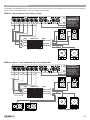
TYPICAL CONFIGURATIONS. . . . . . . . . . . . . . . . . . .
PC260 2 x 3 xover
(advanced live or disco system). . . . . . . . . . . . .
PC260 2 x 2 xover + 1 zone
(advanced live or disco pub system) . . . . . . . . .
PRONET NETWORK . . . . . . . . . . . . . . . . . . . . . . . . . .
The PRONET philosophy. . . . . . . . . . . . . . . . . . . .
Connecting devices . . . . . . . . . . . . . . . . . . . . . . .
Connecting devices to a PRONET NETWORK. .
Assign the ID number. . . . . . . . . . . . . . . . . . . . . .
Working with PRONET . . . . . . . . . . . . . . . . . . . . .
USB2CAN converter. . . . . . . . . . . . . . . . . . . . . . .
CLOCK BATTERY REPLACEMENT. . . . . . . . . . . . . . .
TECHNICAL SPECIFICATION. . . . . . . . . . . . . . . . . . .
Appendix A (signal to power). . . . . . . . . . . . . . . . . .
14
14
14
14
14
14
14
14
15
15
15
16
16
16
16
16
16
17
17
18
18
18
18
18
19
20
21
23
25
27
28
29
29
29
30
30
30
30
31
31
32
33
34
35
3
FCC COMPLIANCE NOTICE
This is a class A digital device, which is marked for use in a commercial, industrial or business
environment, exclusive of used by the general public or used in the home.
This device complies with Part 15 of the FCC Rules. Operation is subject to the following two
conditions:
(1) this device may not cause harmful interference, and
(2) this device must accept any interference received, including interference that may cause
undesired operation.
CAUTION: Changes or modications to this product not expressly approved by the
manufacturer could void the user's authority to operate this product.
NOTE: This equipment has been tested and found to comply with the limits for a Class A digital
device, pursuant to Part 15 of FCC Rules. These limits are designed to provide reasonable
protection against harmful interference when the equipment is operated in a commercial
environment. This equipment generates, uses and can radiate radio frequency energy and,
if not installed and used in accordance with the instruction manual, may cause harmful
interference to radio communications. Operations of this equipment in a residential area is
likely to cause harmful interference in which case the user will be required to correct the
interference at his own expense.
WARNING
This is a class A product. In a domestic environment this product may cause radio
interference in which case the user may be required to take adequate measure.
Under the EM disturbance, the ratio of signal-noise will be changed above 10dB.
4
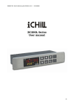
This marking shown on the product or its literature, indicates that it should not be disposed with other household wastes at
the end of its working life. To prevent possible harm to the enviroment or human health from uncontrolled waste disposal,
please separate this from other types of wastes and recycle it responsibly to promote the sustainable reuse of material
resources. Household users should contact either the retailer where they purchased this product, or their local government
office, for details of where and how they can take this item for environmentally safe recycling. Business users should
contact their supplier and check the terms and conditions of the purchase contract. This product should not be mixed with
other commercial wastes for disposal.
The lightning flash with arrowhead symbol within an equilateral triangle is intended to alert the user to the presence of
uninsulated “dangerous voltage” within the product’s enclosure, that may be of sufficient magnitude to constitute a risk of
electric shock to persons.
The exclamation point within an equilateral triangle is intended to alert the user to the presence of important operating and
maintenance (servicing) instructions in the literature accompanying the appliance.
The information contained in this publication has been carefully prepared and checked. However no responsibility will be taken for any
errors. All rights are reserved and this document cannot be copied, photocopied or reproduced in part or completely without written
consent being obtained in advance from PROEL. PROEL reserves the right to make any aesthetic, functional or design modification
to any of its products without any prior notice. PROEL assumes no responsibility for the use or application of the products or circuits
described herein.
5
SAFETY AND PRECAUTIONS
•
CAUTION: Before using this product read carefully the following safety instructions. Take a look of this manual entirely and preserve it for future
reference.
When using any electric product, basic precautions should always be taken, including the following:
– To reduce the risk, close supervision is necessary when the product is used near children.
– Protect the apparatus from atmospheric agents and keep it away from water, rain and high humidity places.
– This product should be site away from heat sources such as radiators, lamps and any other device that generate heat.
– This product should be located so that its location or position does not interfere with its proper ventilation and heating dissipation.
– Care should be taken so that objects and liquids do not go inside the product.
– The product should be connected to a power supply mains line only of the type described on the operating instructions or as marked on the
product. Connect the apparatus to a power supply using only power cord included making always sure it is in good conditions.
– WARNING: The mains plug is used as disconnect device, the disconnect device shall remain readily operable.
– Do not cancel the safety feature assured by means of a polarized line plug (one blade wider than the other) or with a earth connection.
– Make sure that power supply mains line has a proper earth connection.
– Power supply cord should be unplugged from the outlet during strong thunderstorm or when left unused for a long period of time.
– Do not place objects on the product’s power cord or place it in a position where anyone could trip over, walk on or roll anything over it. Do not
allow the product to rest on or to be installed over power cords of any type. Improper installations of this type create the possibility of fire hazard
and/or personal injury.
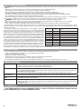
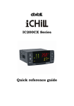
Per Day
Sound Level dBA
Typical
– This product in combination with loudspeakers may be capable of producing Duration
In Hours
Slow Response
Example
sound levels that could cause permanent hearing loss. Exposure to extremely
8
90
Duo in small club
high noise levels may cause permanent hearing loss. Individuals vary
92
considerably in susceptibility to noise-induced hearing loss, but nearly everyone 6
will lose some hearing if exposed to sufficiently intense noise for a period of time. 4
95
Subway Train
The U.S. Government’s Occupational Safety and Health Administration (OSHA) 3
97
has specified the permissible noise level exposures shown in the following chart.
100
Very loud classical music
According to OSHA, any exposure in excess of these permissible limits could 2
1.5
102
result in some hearing loss. To ensure against potentially dangerous exposure
to high sound pressure levels, it is recommended that all persons exposed 1
105
Traffic noise
to equipment capable of producing high sound pressure levels use hearing 0.5
110
protectors while the equipment is in operation. Ear plugs or protectors in the ear
115
Loudest parts at a rock concert
canals or over the ears must be worn when operating the equipment in order to 0.25 or less
prevent permanent hearing loss if exposure is in excess of the limits set forth
here. Keep your's attention that childrens and pets are more suscetible to excessive noise levels.
IN CASE OF FAULT
•
–
–
–
–
–
•
In case of fault or maintenance this product should be inspected only by qualified service personnel when:
There is a flaw either in the connections or in the supplied connecting cables.
Liquids have spilled inside the product.
The product has fallen and been damaged.
The product does not appear to operate normally or exhibits a marked change in performance.
The product has been losted liquids or gases or the enclosure is damaged.
Do not operate on the product, it has no user-serviceable parts inside, refer servicing to an authorized maintenance centre.
TROUBLESHOOTING
No Power
• The device's "POWER" switch is off.
• Make sure the mains AC outlet is live (check if LED PWR lights up).
• Make sure the mains plug is securely plugged into mains AC outlet.
No Sound
• Is the MUTE buttons dis-engaded?
• Is the INPUT METER LED illuminated? If not check if your signal level is too low or check the signal cable, mixer and
other equipment setting and cabling.
• Are you sure your signal cables works properly? check it using a cable tester or replacing with a new one.
Distorted Sound
• Input signal level is too high. Engage the -6dB PAD button on rear panel and/or turn down your level controls..
Different channel
level
• Check if are using a balanced cable for one channel and an unbalanced one for the other, as this would cause a
considerable difference in channel levels.
Noise / Hum
• Enable GND LIFT button on rear panel.
• Whenever possible, preferably use only balanced cables. Unbalanced lines may also be used but may result in noise
over long cable runs.
• Sometimes it helps to plug all audio equipment into the same AC circuit so they share a common ground.
CE CONFORMITY
• Proel PC260 complies with directive 2004/108/EC (EMC), as stated in EN 55103-1 and EN 55103-2 standards and with
directive 2006/95/CE (LVD), as stated in EN 60065 standard.
6
PACKAGING, SHIPPING AND COMPLAINT
• This unit package has been submitted to ISTA 1A integrity tests. We suggest you control the unit conditions immediately after unpacking it.
• If any damage is found, immediately advise the dealer. Keep all unit packaging parts to allow inspection.
• Proel is not responsible for any damage that occurs during shipment.
• Products are sold “delivered ex warehouse” and shipment is at charge and risk of the buyer.
• Possible damages to unit should be immediately notified to forwarder. Each complaint for manumitted package should be done within eight days
from product receipt.
WARRANTY AND PRODUCTS RETURN
• Proel products have operating warranty and comply their specifications, as stated by manufacturer.
• Proel warrants all materials, workmanship and proper operation of this product for a period of two years from the original date of purchase. If
any defects are found in the materials or workmanship or if the product fails to function properly during the applicable warranty period, the owner
should inform about these defects the dealer or the distributor, providing receipt or invoice of date of purchase and defect detailed description.
This warranty does not extend to damage resulting from improper installation, misuse, neglect or abuse. Proel S.p.A. will verify damage on returned
units, and when the unit has been properly used and warranty is still valid, then the unit will be replaced or repaired. Proel S.p.A. is not responsible
for any "direct damage" or "indirect damage" caused by product defectiveness.
INSTALLATION AND DISCLAIMER
• Proel products have been expressly designed for audio application, with signals in audio range (20Hz to 20kHz). Proel has no liability for damages
caused in case of lack of maintenance, modifications, improper use or improper installation non-applying safety instructions.
• These amplifiers are adapted in a properly ventilated, standard professional 19" rack. These units feature ventilation holes on the front and back
panels. Absolutely do not obstruct the ventilation holes. Blocked ventilation can cause damages and fire.
• Do not locate sensitive high-gain equipment such as mixer, preamplifiers, recorders or AD/DA conversion units directly above or below these
amplifiers. Because these amplifiers have a high power density, it ha a strong magnetic field which can induce hum into unshielded devices that
are located nearby. If an equipment rack is used, we recommend locating the amplifier in the bottom of the rack and the mixer, preamplifier or other
sensitive equipment at the top.
• Locate the speakers as far away as possible from radio or television receivers or other sensitive equipment. These amplifiers have a strong
magnetic field which can induce hum and noise into unshielded devices that are located nearby with consequent deterioration of reception of image
and sound.
• Proel S.p.A. reserves the right to change these specifications at any time without notice.
• Proel S.p.A. declines any liability for damages to objects or persons caused by lacks of maintenance, improper use, installation not performed
with safety precautions and at the state of the art.
POWER SUPPLY AND MAINTENANCE
• Clean only with dry cloth.
• Check periodically that the slots for its proper ventilation and heating dissipation are not obstructed by dust, remove the dust using a dry brush
or a compressed air gun.
• These devices have been designed with CLASS I construction and must be connected always to a mains socket outlet with a proctetive earth
connection (the third grounding prong).
• Before connecting the product to the mains outlet make certain that the mains line voltage matches that shown on the rear of the product, a
tolerance of up to ±15% is acceptable.
• To disconnect these equipment from the AC Mains, disconnect the power supply cord plug from the AC receptacle.
•
CHECK THE CONDITION OF THE PROTECTION FUSE, ACCESSIBLE OUTWARD, ONLY WITH THE APPARATUS SWITCHED OFF AND
DISCONNECTED FROM THE MAINS LINE OUTLET.
•
REPLACE THE PROTECTION FUSE ONLY WITH SAME TYPE AS SHOWN ON THE PRODUCT.
•
IF AFTER THE SUBSTITUTION, THE FUSE INTERRUPTS AGAIN THE APPARATUS WORKING, DO NOT TRY AGAIN THEN CONTACT THE PROEL
SERVICE CENTER.
7
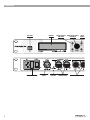
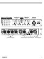
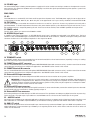
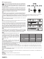
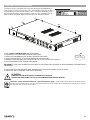
OVERVIEW
USB PORT
mains ac power
8
display
digital audio
input
preset recall
and save
data value select page
and input
scroll
terminate pronet network
button
connections
output connections
ESCAPE BUTTON
PROCESSING MENU
output connections
CHANNEL SELECT
LED METERS
BUTTONS
CHANNEL MUTE
BUTTONS
EXTERNAL MIC
INPUT FOR RTA
input pad button ground lift button
input connections
9
INTRODUCTION
The PROEL PC260 digital loudspeaker controller is based on the CORE DSP platform and features state-of-the-art signal processing,
advanced functions and a very intuitive user interface, with a direct access to all the editing functions and remote control capability.
The 40bit floating point resolution and the 24bit AD/DA converters ensure a perfect signal integrity with a dynamic range in excess of
110dB, for a superior sonic performance.
PC260 includes a full set of functions and features 2 inputs (with AES digital input) and 6 outputs.
Each INPUT features 5 bands of full PARAMETRIC EQ (including parametric, shelving, notch, res. HP and LP, allpass and bandpass),
28 bands of GRAPHIC EQ and 3 bands of an extremely versatile and powerful DYNAMIC EQ. A fully programmable COMPRESSOR/
LIMITER and up to 600ms of delay are also available.
The OUTPUTS include any kind of crossover filters with slope up to 48dB per octave, together with 5 bands of PEQ, fully programmable
COMPRESSOR/LIMITER and up to 600ms of delay.
Additional features include a fully assignable input/output routing and ganging, enviromental temperature compensation of delays,
a GROUPING function and a 1/3 oct. RTA with dedicated MIC input with phantom power.
The SPL Manager, specifically designed for the application in fixed installations, is a very powerful tool that allows to schedule, in 4
different scenes, 16 events on each input and output, including MUTE, level change, COMPRESSOR threshold change and PRESET
change. These events can be then performed automatically according to the internal real-time clock of the unit.
PC260 can be remotely controlled with PRONET software through the USB port on the front panel and it can be included in a PRONET
network through the two RJ-45 connectors on the rear panel.
IMPORTANT
To achieve optimum performance and guard against damage to the processor, your sound system or yourself, please read,
understand and follow all of the directions contained in this manual. Failure to do so may result in improper performance,
loss or injury.
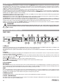
CONTROLS AND CONNECTIONS
FRONT PANEL
1. USB port
USB port for connection to a PC running Windows XP, Vista, Seven 32 or 64 bit. Using the PRONET application, the PC260 can be
operated, edited and configured for installation with an easy to use, intuitive interface.
Any available firmware updates downloadable from www.proel.com can be loaded via the USB port as well, allowing for easy in-field
updates.
2. Display
The display allows for operation and editing of the PC260 without the need of a connected PC. It works in conjunction with the buttons
to operate, navigate and edit the parameters.
In Run time mode the top line it shows the model name, the network operation mode, the lock status, the battery status and the real
time clock. in The rest of the screen it displays the machine name, the name of the currently selected factory or user preset, the
SPLM status and the routing.
Pressing the RCL or SAVE buttons switches to their respective preset menus.
Pressing a processing menu button switches the display to their respective parameters page.
The contrast is set automatically.
3. Preset buttons
RCL (Recall)
Press the RCL button to enter the Recall Preset menu (the RCL button lights). Use the DATA knob to scroll the any factory or user
preset and push it to recall the selected preset into current memory. Pushing the DATA knob completes the preset load operation and
returns the LCD display to Run time mode. To exit without recalling a preset, press ESC.
SAVE
Press the SAVE button to enter the Save Preset manu (the SAVE button lights). In this menu edited presets can be named and saved
to a user preset location. Use the DATA knob to choose the user memory location, to enter the preset name, then complete the saving
operation pressing SAVE again. To exit without storing the current preset, press ESC.
4. DATA entry knob
The DATA knob is used to scroll and select presets and to scroll and edit data parameters and values.
5. PG UP - PG DW buttons
Use these buttons to navigate through the menus pages. The number of the page is diplayed in the right upper corner of the screen
(the button cycles through all available pages).
10
6. ESC button
Press this button to exit from the current menu and return to the Run time mode screen.
7. Processing menu buttons
ROUTING
Use the ROUTING button to enter the routing menu (the ROUTING button lights). In this menu you can set the signal path for each
output.
LEV - level setting
Use the LEV button to enter the levels menu (the LEV button lights). In this menu you can set the level and phase for each input and
output.
XOVER - crossover filters
Use the XOVER button to enter the crossover menu (the XOVER button lights). In this menu you can set the HP or LP filter parameters
for each output.
DELAY
Use the DELAY button to enter the delay menu (the DELAY button lights). In this menu you can set the delay time for each input and
output.
SETUP
Use the SETUP button to enter the setup menu (the SETUP button lights). In this menu you can set the various general parameters.
GEQ - graphic equalizer
Use the GEQ button to enter the graphic equalizer menu (the GEQ button lights). In this menu you can set the equalization of each input.
PEQ - parametric equalizer
Use the PEQ button to enter the parametric equalizer screen (the PEQ button lights). In this screen you can set the equalization of
each input and output.
DEQ - dynamic equalizer
Use the DEQ button to enter the dynamic equalizer screen (the DEQ button lights). In this screen you can set the dynamic equalization
of each input.
DYN - dynamic processors
Use the DYN button to enter the dynamic menu (the DYN button lights). In this menu you can set the signal dynamic processing,
compression and limiting, of each input and output.
SPLM - level manager
Use the SPLM button to enter the level manager menu (the SPLM button lights). In this menu you can set the level management for
each input and output.
RTA - real time analyzer
Use the RTA button to enter the analyzer menu (the RTA button lights). In this menu you can set the level for the RTA MIC input.
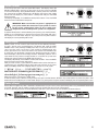
8. Input meters
The input meters monitor the input level of either analog or AES-EBU inputs, depending on the input mode set in the Setup Menu.
Optimal signal-to-noise performance is obtained when the average input level consistently lights the -12dBu (green) and intermittently
lights the -6dBu (Yellow) LED indicators. As the PC260 is a digital audio device, the digital clipping produces very unpleasant results,
so the Clip (red) LED should never light. If the PC260's input does clip, reduce the output level of the connected mixer. The -6dB PAD
button at the rear panel can be used for adjusting the input level also.
9. A - B input MUTE buttons
Each input channel has a lighted Mute button. Pressing the Mute button turns off the input of that channel. The button lights red as
an alert. Press the Mute button again to restore the output channel’s signal.
10. A - B input EDIT buttons
Use these buttons to access the editing of the input's parameter (the buttons light blue when pressed). Pressing these buttons
while in Run time mode, you enter the LEVEL menu (the LEV button also lights) where you can adjust the level of the selected input.
If a processing button, such as DELAY, GEQ, PEQ, DEQ, DYN, has been previuosly selected, pressing the edit button you choose the
channel to process.
11. Output meters
Each output channel has a four-segment VU meter. Meter withdrawal point can be pre or post mute, as set on SETUP page. The red
segment indicates that limiting is being applied to the output channel if the limiter is engaged or, if the limiter is disabled, indicates
clipping of the D/A converters, which should be avoided by adjusting the Output Level.
It is important to understand how the meters work and what they are displaying. The Output Levels are displayed as “dB to Limiter
Threshold”. In other words, the meters will display the headroom between the output level and the limiter threshold. When viewed in
conjunction with the gain reduction meters in the dynamic menu of the selected channel (use DYN button), this provides a complete
display of level and headroom before and after limiting has been engaged to allow system levels to be optimized. This also means
that the output metering will be displayed differently depending on the limiter threshold setting.
12. Output MUTE buttons
Each output channel has a lighted Mute button. Pressing the Mute button turns off the output of that channel. The button lights red
as an alert. Press the Mute button again to restore the output channel’s signal.
13. Output EDIT buttons
Use these buttons to access the editing of the output's parameter (the buttons light blue when pressed). Pressing these buttons while
in Run time mode, you enter the LEVEL menu (the LEV button also lights) where you can adjust the level of the selected channel. If a
processing button, such as XOVER, DELAY, PEQ, DYN, has been previuosly selected, pressing the edit button you choose the channel
to process.
11
14. RTA MIC input
This balanced XLR input is fitted a phantom power to supply and it can be used for connecting a condenser microphone for acoustic
measurements. This allows the PC260 to measure and display in real time the signal reproduced through the speakers system in the
acoustic environment.
REAR PANEL
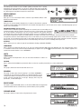
15. AC ~
The PC260 features a standard IEC A.C. inlet that will accept universal power cords. The PC260 power supply is auto-ranging and can
accept voltages from 100 - 240 V AC, 50 – 60 Hz. Only A.C. cords approved for use in your country should be connected to the PC260.
16. FUSE holder
The A.C. inlet includes a fuse holder that contains the mains fuse as well as a spare fuse. If necessary, replace the fuse only with a
specified 5x20mm, T 1 A 250 V replacement. Disconnect A.C. power before replacing a fuse. Before turning the unit back on, assess
the condition of the A.C. receptacle powering the unit. If the fuse continues to blow, refer to PROEL qualified service personnel.
17. POWER switch
The A.C. power switch turns power to the PC260 On and Off.
18. AES/EBU Digital Input
In addition to the analog audio inputs, an AES/EBU digital stereo input is provided and selectable in the SETUP menu. The input
conforms to IEC standard 60958 Type I. Connections must be made with three-conductor, 110-Ohm, twisted pair cabling and an XLR
connector. It allows to use all sampling frequencies in the range of 32-96 kHz.
19. TERMINATE switch
In a PRONET network the last connected device must be terminated (with an inner load resistance) especially in a long run cabling:
press this switch if you want to terminate the unit.
20. PRONET Network OUT connector
This is a standard RJ45 CAT5 connector (with optional NEUTRIK NE8MC RJ45 cable connector carrier), used for transmission of remote
control data over long distance or multiple unit applications. See PRONET section further in this manual.
21. PRONET Network IN connector
This is a standard RJ45 CAT5 connector (with optional NEUTRIK NE8MC RJ45 cable connector carrier), used for transmission of remote
control data over long distance or multiple unit applications. See PRONET section further in this manual.
22. Balanced XLR Output connectors
Each output channel has an electronically balanced XLR connector for the connection to the system's amplifiers.
IMPORTANT: Care must be taken to assure that each output is connected to an appropriate amplifier and loudspeaker to
avoid damage or unexpected results. Note that a new preset may change the assignment of channel and its frequency
range. For instance an output assigned to Hi frequency speakers in one preset, may be assigned as a sub output in another.
See Configurations section further on this manual.
23. Balanced XLR Input connectors
Each input has an electronically balanced, locking XLR connector. In stereo or dual modes, connections to both inputs must be made.
In mono modes, only one connection is needed, typically to Input A.
24. Balanced XLR Thru connectors
Each analog audio input is linked directly to an XLR male connector. The signal does not undergo any digital conversion or processing.
These connectors are used to pass input audio to a second PC260 used as a slave or to other audio inputs in the system.
25. – 6dB PAD switch
Input levels to the PC260 can be reduced by 6dB prior to the A/D converter to compensate for higher-level output from mixers and
other audio devices. The PC260‘s Input level Meters (8) will indicate incoming signal level and whether attenuation is required.
26. GND LIFT switch
This switch lift the ground of the balanced audio inputs from the earth-ground of the PC260. If you have HUM noise problem on the
whole loudspeaker system attached to your PC260 try to change the position of this switch. Please note that to have an effect all
cables must be balanced.
12
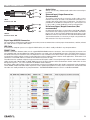
CABLE CONNECTIONS
hot
cold
ground
ground
cold
hot
Digital Input AES/EBU Connection
tip - hot
Always use correctly shielded audio cables when connecting to
the PC260.
ring - cold
Balanced Input / Output Connections
sleeve - gnd
(Recommended)
To minimize induced noise caused by audio cables and to
INPUT
maximize
the length of cables used, balanced connections are
Jack
(balanced)
INPUT
Balanced male XLR
OUTPUT
Balanced female XLR
Audio Cables
strongly advised for both Inputs and Outputs. The XLR jacks
provided on the PC260 are configured as pin 1 ground, pin 2 hot
(+), pin 3 cold (-). Cable shielding must be connected to pin 1.
tip - hot
Un-balanced Input / Output Connections (Not
cold
recommended)
Un-balanced connections can be made to the
PC260, although
ground
induced noise from cabling may be increased. Cables should also
be less than 15” (5m) in length. Unbalanced connections can be
INPUT
6dB lower in level as well. To match the audio level obtained with
Jack (unbalanced)
a balanced connection, it is necessary to tie pin 3 to ground at the
*note:
both cold and
ground
XLRconnect
connector.
This
may increase noise.
to make cable from balanced to unbalanced
This connection is wired like the audio analog connection, but we recommend the use of the proper threeconductor, 110-Ohm, twisted
pair cable, do not use a generic MIC cable.
USB Cable
To connect the computer you can use a Type A-B USB cables, this cable is readily available in any computer dealers.
PRONET Cable
Network connections between nodes are via rugged NEUTRIK NE8MC ethercon connectors; these are high quality connectors and
are compatible with standard RJ45 plugs. Node connections are made using standard RJ45 connectors and CAT5 cable. Long runs
should be solid core, but standard is fine. The implication is that stranded is more robust and less prone to breakage, it is therefore
suggested that solid should be used for install applications while stranded is better suited to rental applications. Termination of all
connectors at each END node is essential for the network to function correctly.
The table shows the standard straight-through convention for CAT5 patch cables. The straight-through cable uses the same connection
coding at both ends T568A-T568A or T568B-T568B, these are the most common cable used between network nodes. Bear in mind
though that only Pins 1, 2, 4, 5 are used to link the PRONET network devices.
Any CAT5 or CAT6 cable could be used, we recommend to use the pre-assembled cables with shield in combinantion with the optional
carrier NE8MC, reliable self-made cables require the use of a good crimping tool that usually is too much expensive. The CAT5 or CAT6
net cables are readily available in any computer dealers. The NEUTRIK NE8MC ethercon carrier is available from PROEL.
13
OPERATING MODE
PC260 has two operation modes:
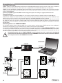
REMOTE MODE using PRONET software
Connect the unit to a PC running Windows and PRONET software by means of USB port or NETWORK port, push the Online button on
the PRONET button bar and after some seconds the following screen appears on the display, now the PC260 is controlled remotely
by the PC and all controls are disabled, if you want to return in run time mode push the offline button.
See the further PRONET CONFIGURATION section for how to build in details a PRONET network.
Refer to the PROEL web site (www.proel.com) to download the PRONET software and documentation.
The PROEL LOUDSPEAKER LIBRARIES can be downloaded from the web site in your computer, then loaded in the PC260 unit using
the PRONET software, refer to its documentation for details.
RUN TIME MODE
The run time mode is the normal operating mode of the PC260, then after turn on the unit the following screen appears:
The display shows the main status of the unit: name, preset, SPLM status, routing, real time clock. All control buttons are active.
PRESETS
The PC260 features four types of preset:
DEAFAULT Presets
The PC260 comes with one Default preset identified by a "D" letter after the number. This is a preset with all the parameters in Default
position, which can be used as a starting point for creating your own settigns from scratch or for RESETTING and existing User or
Protected preset.
FACTORY Presets
The PC260 comes with Factory presets including the settings for PROEL loudspeaker systems. A factory preset is identified by
a "F" letter after the number. Only the the input processing parameters can be edited in Factory presets, which is indicated by
a KEY symbol in the first line of the display.
When a input parameter is modified an asterisk "*" appears after the "F" letter on the display indicating that the preset is edited.
Modified Factory presets cannot be saved in the Factory locations, but only in User location: in this case they become Protected
presets.
IMPORTANT: always be sure to recall the Factory preset for the right loudpeaker system and to make the right output
connections., otherwise loudspeaker system damages could be occur.
PROTECTED Presets
When you store a modified factory preset in a user prese, it becomes a Protected preset, which is identified by a "P" letter
after the number. As for the Factory preset, only the input processing parameters can be edited, which is indicated by a KEY
symbol in the first line of the display.
When a input parameter is modified an asterisk "*" appears after the "P" letter on the display indicating that the preset is edited.
Usually Protected presets are created when you need to modify the input parameters of a Factory preset and then save it.
USER Presets
A User preset is identified by a "U" letter after the number. When the unit is set in FULL EDIT MODE (see further in this manual), both
input and output parameters can be edited in a User presets.
When a input parameter is modified an asterisk "*" appears after the "U" letter on the display indicating that the preset is edited.
14
Recall a Preset
To recall a preset, press the front panel RCL button. The display shows the
RECALL PRESET menu and the current preset in the list of those available
in the internal memory. Using the DATA knob scroll the preset list and select
the preset to be recalled. Valid presets will display the preset name, empty
presets will not display any name. Select a valid preset and push the DATA
knob to confirm.
The display will prompt, “Push DATA to confirm, ESC to abort”. Press the DATA
knob to confirm and load the new preset.
IMPORTANT: Make sure that the new preset is appropriate for
your system, and that the connections to your system are correct
for the current configuration. Failure to do so could cause
unexpected results or damage to the system or its components.
To exit the Recall process without loading a new preset, press the ESC button,
SETUP or any active buttons in the processing menu. ESC button will return
the display to run-time mode. Setup or any active processing menu buttons
will display the corresponding edit screen.
Save a Preset
Edited presets can be saved in one of the User Preset memory locations.
To save a preset, press the SAVE button. The display will show the SAVE
PRESET menu. If the previosly loaded preset was a user preset the cursor
starts from the same user preset. If the previously loaded preset was
factory preset the cursor starts from the first user preset. Use the DATA knob
to select the user destination. Locations that already have presets saved in
them will display a preset name. Empty locations will display “default” in the
name field. You may select an empty location, or a location of a preset that
will be over-written and push the DATA knob to confirm.
The display will prompt, “Push DATA to confirm, ESC to abort”. Press the DATA
knob to confirm and save the new preset.
Now you have to enter a name: Rotate the DATA knob to select the letter or
symbol, then push the DATA knob to skip to the next character in the name
field. The PC260 provides the complete ANSI character set, in this order:
a
!"#$%&'()*+,-./0123456789:;<=>?@
ABCDEFGHIJKLMNOPQRSTUVWXYZ[\]^_`
abcdefghijklmnopqrstuvwxyz{|}~
When the preset is named, press SAVE again.
To exit the Save process without saving a new preset, press the ESC button, SETUP or any active buttons on processing menu. ESC
button will return the display to run-time mode. Setup or any active processing menu buttons willdisplay the corresponding edit screen.
Delete a Preset
Also if doesn't happen very often, sometimes could be necessary to erase a preset, particularly when using the PRESET LOCK mode
or the SPL manager and you need to cancel previously stored preset that rae not used anymore.
To erase a preset you have to recall the "Default" preset (no. 1) and save it in the user location you want to erase:
15
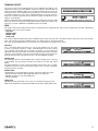
SETUP
The Setup menu allows access PC260’s global parametersThis is where
preferences for many functions can be set or adjusted. Use page up (PG UP)
and page down (PG DW) to scroll between setup pages. Rotate the DATA knob
for selecting the values/data and push it to enter them.
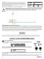
MISCELLANEOUS
METERS-MUTE
Here you can set if the output meters show the signal before (PRE) or after
(POST) the mutes button.
TEMPERATURE
Here you can set the ambient temperature, in order to calculate the speed of
sound for converting delay times into distance. As default the temperature is set in celsius units scale, in the following page you can
set the unit as Fahrenheit.
INFORMATION NOTE: Speed of sound
Sound travels at different speeds depending on the density of the surrounding air it is
traveling through. Cold air is denser than warm air thus, travels slower than it would if
m/s
the air was warmer. Temperature can have a major influence with greater distances,
particularly with respect to widely separated speaker arrays surrounding the audience
for example. Temperatures might vary wildly between an indoor environment and an outdoor evening environment for example.
The speed of sound at room temperature of 20 °C is 343 meters per second. At freezing temperatures sound travels at 331 meters
per second. V is the speed of sound and T is the temperature of the air. This formula finds the average speed of sound for any given
temperature (celcius). The speed of sound is also affected by other factors such as humidity and air pressure.
IN-SELECT
Here is where you can select the type of input between Analog and Digital AES/EBU).
COMM MODE
Here is where the communication port is set. You can choose between USB and Pronet Network port. The communication status
is :showed in the first line of the Run time mode display: if appears this symbol
the communication is set as USB, if appears this
symbol the communication is set as NETWORK.
V
= 331 + (0.6 * T)
UNITS
TEMPERATURE
Here is where the temperature units can be chosen between in Celsius or
Fahrenheit.
EQ-BAND
Here is where the bandwidth for parametric filters can be set as quality factor (Q) or as octave width (OCT).
TIME
This page is where the internal real time clock is set.
GANGING
This page is where the channel ganging is set. When GANGING is
activated all the channels parameters are linked toghether, if you
change a parameter in one of these channels also the same parameter
of the channels ganged with it changes. Ganging links only the
paramaters, no the audio signal.
pc260:
DEVICE NAME
This page is where the PC260 name is set. Push the DATA knob to navigate then
rotate the DATA knob to scroll the value, confirm all data pressing SETUP.
CHANNEL NAME
This page is where a name can be assigned to each chann.
16
FIRMWARE UPDATE
This page is where the PC260 Firmware can be updated from USB port. To
update the firmware a PC with PRONET software installed is required. Both the
firmware and the PRONET software can be downloaded from proel web site
(www.proel.com). In the PRONET documentation you can find the instruction
to update the firmware. Press ESC or PG UP/DW buttons to escape from this
page, press SETUP to proceed with the firmware update, the following screen
appears on the display:
Now the PC260 still waiting the PRONET program to send the firmware thru USB
port, if you want to escape from this procedure without update the firmware you
have only a solution: TURN OFF and TURN ON again the PC260.
LOCK
This page is where the PC260 can be locked or unlocked by the installer/operator. There are four LOCK levels available, indicated by
a padlock in the first line of the display:
FULL EDIT
PARTIAL LOCK
PRESET LOCK
TOTAL LOCK
For setting a different LOCK level, rotate the DATA knob to select the level, press the DATA knob to confirm the new level and then
input a password using again the DATA knob. Press SETUP again for confirming all data.
Press ESC or PG UP/DW buttons to escape from this page without changing the lock status.
FULL EDIT
This is the defult LOCK level when you turn on the PC260 for the first time
or when an operator performs a FULL SYSTEM RESET. All routing setting
sare available and all DSP input and output parameters are accessible and
adjustable (only input parameters for Factory and protected presets). Resulting
settings can be saved into any User Preset location for later recall. Editing can
be performed from the control panel or from a PC with PRONET software.
PRESET LOCK
This LOCK level allows only the USER Presets saved in the processor's memory
to be recalled. The only other parameter accessible is the inout and output
MUTE
This LOCK mode level can be used by installators who want to save a number
of different presets for the sound system and then lock any other parameter
except the preset recalling.
PARTIAL LOCK
Limited editing can be performed on Factory, Protected and User presets:
- INPUT parameters: DELAY, GEQ, PEQ, DEQ, DYN, mute and level;
- OUTPUT parameters: mute and TRIM level;
- SPL Management.
TOTAL LOCK
NO editing can be performed on the processor, including the preset recall.
Note: when the SPLM is activated the PC260 is forced in the TOTAL LOCK status.
17
PROCESSING MENU
The following diagram shows the internal processing structure of the PC260.
Using the PROCESSING menu in conjuction with EDIT and PG UP/PG DW buttons, all the above sections can be edited.
EDITING processing menu parameters
ROUTING - signal routing
This page is where each output channel is assigned to
an input channel A or B or to the sum of A+B channels.
Press the ROUTING button to access, then push the
DATA knob to select the output to edit and rotate the
knob to select the value. Confirm all data pressing
ROUTING again, or press ESC to exit without changing
the routing
LEVEL - levels and phase polarity
The LEV section is used to adjust input and output levels. Press the
LEVEL button and the EDIT button of the channel you want to edit. Push
the DATA knob to select the parameter to edit and rotate the knob to
adjust it:
The LEVEL value can vary from -30dB to +6dB for the input channels
and from -30dB to +15dB for the output channels.
The TRIM value is present only in the output channels and can be set between
-6dB to +6dB. This parameter can be adjusted also if the PC260 unit is in
PARTIAL lock status.
The PHASE value can be set between 0° (normal polarity) or 180° (reversed
polarity).
XOVER - crossover filters
The PC260’s crossover is an advanced frequency division process that is
accomplished by applying a variety of high-pass and low-pass filters to a
predetermined set of crossover points.
Speaker systems are generally made up of several drivers that are dedicated to a
specific range of frequencies, which results in an efficient reproduction of the audio
spectrum and a smooth sound. The PC260 crossover routes frequencies to the appropriate
drivers to accurately reproduce the sound. The crossover network can also be used to
ensure that low-frequency energy is not accidentally routed to the mid-range or tweeter
drivers that may result in potential damage.
Available PC260 crossover parameters are Type and Frequency. To access the Xover section,
press the XOVER button and then the EDIT button of the output you want to edit. Push the
DATA knob to select the parameter to edit and rotate the knob to adjust it:
18
For each output channel two crossover points can be set, which are named Xo1
and Xo2. Please note that in the FLAT default preset both are set as Thru (the
signal passes thru without filtering process).
The parameters are:
LP/HP
The crossover filter generally consists of a low pass filter in one channel and a
high pass filter in the adjacent channel.
H-pass: a high pass filter passes frequencies above the crossover point and
attenuates those below.
L-pass: a how pass filter passes frequencies below the crossover point and
attenuates those above.
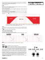
As standard Xo1 is set as H-pass (HIGH-PASS) and Xo2 is set as L-pass (LOWPASS), but they can be set also differently.
See the figure below (note: all the following figures are taken from the PRONET
software):
CUT OUT
CUT OUT
PASS THRU
This figure shows the frequency spectrum of an output with Xo1 set as H-pass, Butt 24, 100Hz and Xo2 set as
L-pass, Butt 24, 1KHz all signal highlighted is cut out.
TYPE
The PC260 offers a wide choice of HiPass and LoPass filters with different slopes
and responses. The Type parameter defines the characteristics of the crossover
filter:
• Butterworth: 6dB, 12dB, 18dB, 24dB, 48dB
• Bessel: 12dB, 18dB, 24dB 48dB
• Linkwitz-Riley: 12dB, 24 dB, 48dB
Each filter can be bypassed setting it as "thru".
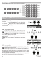
The figures below show the various slopes with the FREQ parameter set at 1 kHz:
butterworth
bessel
linkwitz-riley
12
6
48
24
18
12
12
48
24
18
24
48
FREQ
Frequency offers a selectable frequency range from 20 Hz to 20 KHz.
DELAY
PC260 offers input and output delay.
Master A and B input delay is useful for compensating
different arrival times of sound originating from loudspeakers
that are closer or further away from the listener than others.
Channel 1 to 6 output delay is useful for compensating physical offsets of the
acoustic centers of transducers within a loudspeaker cabinet. For example,
due to cabinet construction, the acoustic center of a high frequency transducer
may be placed behind or in front of the acoustic center of the low frequency
transducer. The Delay parameter can align the audio signal between the
multiple transducers within the loudspeaker. The output delay can be useful
also to align the subwoofer, usually placed at ground level, with the satellite
speakers suspended. Available delay parameters are DELAY and UNITS:
The DELAY parameter allows the user to set the Delay time values (0 to
+300.00ms or 0 to 200m/675ft).
19
The UNIT parameter allows to set the delay unit in us (microsecond / 10 -6 s), ms
(millisecond / 10-3 s), mm (millimeter / 10-3 m), m (meter), inch and feet values.
To access the delay section, press the DELAY button and then the EDIT button
of the channel you want to edit. Push the DATA knob to select the parameter to
edit and rotate the knob to adjust it:
Note: The effect of air temperature is also automatically calculated for the total
delay time using the Temperature value entered in the Setup Menu.
IMPORTANT: Make sure that the Master A and B input channels delay is exactly the same when an output is routed from
the A+B sum. We recommend to link the inputs (ganging) to make sure that the same delay is applied to both inputs.
Failure to do that could cause unexpected results on each A+B sum output (internal comb filtering).
INFORMATION NOTE: Subwoofer delay time adjustment
PC260 processor allows the adjustment of the delay to allow the correct alignment of the system. The default setting gives the correct
temporal alignment for when the tops are set up directly above the subwoofers; in any other case, the delay should be adjusted to
correct the alignment. The delay to be added to the preset can be calculated quite simply. The above figure showsan example of this
alignment. The system is composed of a flown satellite and a subwoofer positioned on the ground. The sound coming from the sub
covers a shorter distance that the top in reaching the listener (position P), it is therefore necessary to delay the emission of the sub
to restore the correct temporal alignment. If d is the distance the subwoofer is placed in relation to the theoretical alignment position
(the dashed image in the picture), the delay to be set on the processor can be calculated using the following equation:
Ts = d / c
where c is the speed of sound (about 344 m/s). The PC260 processor also allows the delay to be set directly in meters or feet.
Example: If the subwoofer is positioned 2 metres forward from the line of satellite units, the equation would work as follows:
d=2m
T = d / c = 2 / 344 = 0.006 s = 6 ms
GEQ - graphic equalizer
In the GEQ section you can control the 28-bands 1/3 octave graphic equalizer of each
input channel. The GEQ is controlled using gain sliders, just like you would do in a normal
graphic EQ.
To access the first page of the graphic EQ section, press the GEQ button and then the EDIT button of
the input you want to edit. Push the DATA knob to select the parameter to edit (GAIN or FREQUENCY)
and rotate the knob to adjust it:
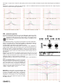
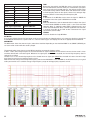
In the second page of the GEQ section there is a useful BYPASS function for comparing the sound with and without EQ. In addition,
it's possible to select the response TYPE of the equalizer, by changing the shape or “Q” of the single cells. The behaviour of each
type is shown below.
The “EZCurve” type is based on the Proel’s EZCurve analog Graphic Equalizer’s response. It has a “Q” that varies with cut/boost
applied - wider ‘Q’ at lower values of cut/boost - resulting in a smoother response when smaller amounts of EQ are added.
20
The “Type1” response has a fixed “Q”, giving more precise control, and offers the flattest response when boosting groups of adjacent
faders.
The “Type2” response has a fixed “Q” too, like Type1, but it has a different reference and a lower value of the “Q” shape: this gives
a different response from Type1 equalization.
EZcurve, 1 KHz, +3 /6 / 12 dB
Type 1, 1 KHz, +3 /6 / 12 dB
Type 2, 1 KHz, +3 /6 / 12 dB
EZcurve, 1 KHz + 1.25 KHz, +3 / 6 / 12 dB
Type 1, 1 KHz + 1.25 KHz, +3 / 6 / 12 dB
Type 2, 1 KHz + 1.25 KHz, +3 / 6 / 12 dB
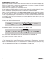
PEQ - parametric equalizer
To access the parametric EQ section, press the PEQ button and then the EDIT
button of the channel you want to edit. Push the DATA knob to select the
parameter to edit and rotate the knob to adjust it. Use PG UP and PG
DW buttons for scrolling the pages of the five filters available for each
input and output.
The PC260 PEQ provides a very powerful and complex set of multi-mode filters.
Care must be taken when configuring these filters as they interact and can
produce unexpected results. Using the PRONET PC application is strongly
recommended to set all but the most simple eq curves.
Each band of the PEQ can be configured for a specific filter TYPE, FREQUENCY,
SLOPE, SHAPE or GAIN setting. Each filter band can be deactivated using the
BYPASS parameter (as default the BYPASS is active, sot he signal passes
thru the filter cell unchanged). Please note that changing the filter TYPE the
gain parameter goes to zero: this avoids excessive sound changes during a
performance.
Attention must be paid to the ultimate output gain through the rest of the
PC260’s audio path, as it is possible to boost frequency ranges to the point
where the internal audio paths of the system may clip. A simple rule can be
applied to avoid this: cutting is better than boosting.
The following graphs show how the signal changes when a specified filter is
used.
Peak or Parametric filter. A parametric equalizer
has three parameters that determine the frequency
response: frequency, Q or octave (bandwidth) and
gain. Parametric filters are ideal for identifying,
isolating and correcting problematic frequency
ranges. The graph shows the response at 1KHz,
+15dB or -15dB, oct=0.05 / 1.0 / 3.0.
Notch filter. A notch filter has two parameters that
determine the frequency response: frequency, Q
or octave (bandwidth). Notch filters are ideal for
identifying, isolating and correcting problematic
frequency, in particularly to cut a microphone
feedback. The graph shows the response at 1KHz,
oct=0.05 / 1.0 / 3.0.
21
Low-shelf. A shelf filter has three parameters that
determine the frequency response: frequency, gain
and slope. In a Low-shelf filter the frequencies
below its frequency setting can be boosted or cut.
The extent of width of the filter’s transition band is
the Slope, it can be fixed at 6 or 12dB or vary in this
range. The graph shows the response at 1KHz, +15dB
or -15dB, 6 or 12 dB slope.
High-shelf. A shelf filter has three parameters that
determine the frequency response: frequency, gain
and slope. In a High-shelf filter the frequencies
above its frequency setting can be boosted or cut.
The extent of width of the filter’s transition band is
the Slope, it can be fixed at 6 or 12dB or vary in this
range. The graph shows the response at 1KHz, +15dB
or -15dB, 6 or 12 dB slope.
Res Low pass. A resonance low pass filter has two
parameters: frequency and Q. This is a low pass
filter with 12dB slope and it can be used alone or in
conjuction with a xover filter using the variable Q to
model the response in the cut off frequency range.
The graph shows the response at 1KHz, Q at min or
max value.
Bandpass. A bandpass filter has two parameters:
frequency and Q. This is a typical band pass
filter with 6dB slope. Note that the response is
fundamentally NOT a flat-topped response (so it is
not constructed from a high pass and low pass). The
graph shows the response at 1KHz, Q at min or max
value.
Res High pass. A resonance high pass filter has two
parameters: frequency and Q. This is a high pass
filter with 12dB slope and it can be used alone or in
conjuction with a xover filter using the variable Q to
model the response in the cut off frequency range.
The graph shows the response at 1KHz, Q at min or
max value.
All pass 1st. An all pass first order filter introduces a
phase shift that gradually changes from -180° above
the centre frequency to the specificed value at the
centre frequency tending towards 0° below the
centre frequency. This filter can be used to shape
the phase behaviuor of a specified output. The graph
shows the phase response centered at 1KHz at 45°
steps.
All pass 2nd. An all pass second order filter affects
the frequency at which the phase effectively flips
180° and the ‘speed’ (using the Q parameter) at
which this transition occurs. This filter can be used
to shape the phase behavior of a specified output.
The graph shows the phase response centered at
1KHz with 0.35, 0.70, 3.05 Q steps.
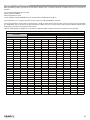
The following table details the type of filters that can be selected for each of the PEQ’s 5 bands and their parameters:
22
TYPE (PC260)
TYPE (PRONET)
FREQ
GAIN
SHAPE
SLOPE
Peak
Param. Eq.
15.6 Hz - 22.627 KHz
+/- 15 dB
Q = 28.5 - 0.4 / oct = 0.05 - 3.0
-
Notch
Notch
15.6 Hz - 22.627 KHz
-
Q = 28.5 - 0.4 / oct = 0.05 - 3.0
-
LoSh6
Low Sh. 6dB/oct
15.6 Hz - 22.627 KHz
+/- 15 dB
-
-
LoSh12
Low Sh. 12dB/oct
15.6 Hz - 22.627 KHz
+/- 15 dB
-
-
LoShV
Low Sh. var.
15.6 Hz - 22.627 KHz
+/- 15 dB
-
6.0 - 12 dB
HiSh6
High Sh. 6dB/oct
15.6 Hz - 22.627 KHz
+/- 15 dB
-
-
HiSh12
High Sh. 12dB/oct
15.6 Hz - 22.627 KHz
+/- 15 dB
-
-
HiShV
High Sh. var.
15.6 Hz - 22.627 KHz
+/- 15 dB
-
6.0 - 12 dB
ResLp
Res. Lowpass
15.6 Hz - 22.627 KHz
-
Q = 3.30 - 0.35
-
Bandpass
Bandpass
15.6 Hz - 22.627 KHz
-
Q = 28.5 - 0.4 / oct = 0.05 - 3.0
-
ResHp
Res. Highpass
15.6 Hz - 22.627 KHz
-
Q = 3.30 - 0.35
-
Allp1
Allpass 1st ord.
15.6 Hz - 22.627 KHz
-
degrees = -3° to -179°
-
Allp2
Allpass 2nd ord.
15.6 Hz - 22.627 KHz
-
Q = 3.30 - 0.35
-
TYPE (PC260)
TYPE (PRONET)
FREQ
GAIN
SHAPE
SLOPE
DEQ - dynamic equalizer
To access the first page of the dynamic EQ section, press the DEQ button and then the EDIT
button of the input you want to edit. Push the DATA knob to select the parameter to edit and
rotate the knob to adjust it. Use PG UP and PG DW buttons for scrolling the pages of the
three dynamic EQ filters available for each input.
The first line of the display shows the EQ filter number (DEQ1, DEQ2, DEQ3). For each EQ filter you
can set many parameters: GAIN, FREQ, BAND, TYPE, THRESHOLD and TIME are in the first page
of the filter, MODE, SIDECHAIN and BYPASS are in the second page. The first page shows also the
input LEVEL meter and the second page the GAIN meter.
When Input A and Input B channels are linked (see SETUP GANGING section), the display first line
shows CHA&B and the DEQ parameters are modified in the same way in both inputs A and B.
IN A DEQ, EACH CELL IS AN EQ FILTER WHERE THE GAIN PARAMETER IS DYNAMICALLY
CONTROLLED BY THE LEVEL OF THE INPUT SIGNAL.
All parameters can be adjusted separately for each cell, these are:
GAIN
Sets the gain parameter for the filter.
FREQ
Sets the reference frequency for the filter.
BAND
Controls the filter bandwidth (available only for parametric type
and not for shelving types).
TYPE
Selects the type of filter. Note that when changing the filter type
the GAIN is set to zero.
EQ filter types available are:
"Param" as Parametric filter,
"LoSh" as Low Shelf 6dB/oct. filter,
"HiSh" as High Shelf 6dB/oct. filter.
THRE
Threshold sets which the level of the input signal that congrols
the gain of the dynamic EQ filter. According to the MODE setting
(ABOVE / BELOW), when the input signal reaches the threshold,
the gain increase or reduction of the dynamic filter is activated
or deactivated.
The amount of gain increase or reduction is shown by the GAIN
METER (see also MODE parameter). The threshold level is
referred to 0 dB: if the input has no attenuation, it corresponds
to 0 dBu (775 mV) of the input signal, so Threshold = +21 dB (max
signal) means no detection of input signal.
23
Time definitions for DEQ cells.
Label
Attack Time (ms)
Release Time (ms)
Fast 1
1
10
Fast 2
4
40
Medium 1
8
80
Medium 2
20
200
Medium 3
40
400
Slow 1
80
800
Slow 2
100
1000
TYPE (signal equalization)
SIDECH: SIDE filter
Low Shelf at freq. f0
Low pass, cut freq. f0
Peaking centered at f0
pass band centered at f0
High Shelf at freq. f0
High pass, cut freq. f0
TIME
Determines how quickly the DEQ filter reacts to signals that reach
the threshold (attack) and how slowly it is restored after signal goes
goes away from the threshold (release). The table to the left shows
all possible settings and the relative attack and release time. In order
to avoid "pumping" effect on the signal, choose a fast setting for high
frequency EQ and a slow setting for low frequency EQ.
MODE
It determines if the DEQ filter works when the signal is ABOVE the
threshold or when the signal is BELOW the threshold.
SIDECH
Sidechain determines how the detection block analyzes the signal.
In normal mode (NORM) the whole signal is sent to the threshold
detection block. In sidechain mode (SIDE) a filtered signal is sent
to the threshold detection block. The filter applied for the sidechain
is choosen according to the TYPE of filter selected for the signal
equalization (see the table).
BYPASS
Enable or disable the single DEQ filter.
LEV METER
As show in the block diagram, the level meter receives the signal after the sidechain block, so it shows the signal that controls the
threshold detection block for a specific filter. It's useful for checking your sound program and set an appropriate threshold level.
GAIN METER
The GAIN meter shows the amount of gain / reduction of the filter. Depending on how the filter MODE is set (ABOVE / BELOW) you
can see the filter action while the sound is played.
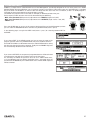
The example below shows how to use the DEQ for obtaining an automatic loudness effect.
In filters 1 and 3, low and high frequencies are boosted when the signal is BELOW the threshold: this means that the sound is richer
and more defined with a low level signal. Whenever the signal goes above the set theshold, the low and high frequency boost is
reduced or cancelled.
The filter 2 has a cut in the mid-high region that is activated when the signal goes ABOVE the threshold: this means that with a high
level signal the sound is more pleasant and less harsh.
Note that the time setting is decreasing with frequency and that the SIDECHAIN is set to NORMAL for the HF band because, in a typical
audio spectrum there isn't sufficient energy in high frequency range for driving properly a dynamic control.
24
DYN - dynamic processor
To access the first page of the dynamic section, press the DYN button
and then the EDIT button of the channel you want to edit. Push the
DATA knob to select the parameter to edit and rotate the knob to
adjust it. Use PG UP and PG DW buttons for scrolling between the
two pages available.
Each input and output of the PC260 has a dynamic processor hat can be
configured as limiter or compressor and that provides a very complete set of
parameters to control the sound dynamics. The most typical setups includea
limiter on the outputs for protecting the speakers from excessive power and
a compressor on the inputs for enhance the performance of the loudspeaker
system or for controlling the sound pressure level.
THRE
This parameter set the threshold level for the compressor/limiter. Below the
threshold no compression/limiting occurs, above the threshold the signal is
compress or limited as indicated in the dynamic curve. The threshold level is referred to the 0 dB: if the input has no attenuation it
corresponds to 0 dBu (775 mV) of the input signal, so Threshold = +21 dB (max signal) means no detection of input signal.
See further the SPEAKER PROTECTION SETTING information note for more details.
ATK
Attack time: determines how quickly the compressor/limiter reacts when the
signal reaches above the threshold.
REL
Release time: determines how slowly the compressor/limiter restores its normal
gain after the signal goes below the threshold.
Attack and release times are dependent to the music genre and to the type of
loudspeaker connected to the outputs. For an compressor/limiter on the inputs
we suggest to start using a medium-long time for both attack and release
time, such as 50mS for the attack and 450mS for the release, then shortest or
longer the times if some audible artefacts are noted. For an output limiter for a
specified speaker type we suggest to start with the times indicated in the table
below and then adjust them if some audible artefacts are noted.
MODE
This parameter is used to set the dynamic processor as compressor (Comp)
or limiter (Lim). When it is set as limiter the RATIO parameter is not available
: 1. In limiter mode also the KNEE
because the limiter has a fixed ratio of
parameter, fixed as hard knee, and the GAIN parameter are not available.
RATIO
Available only when the dynamic processor is set
Minimum frequency (HPF) Attack time (max) Release time (min)
as compressor, this parameter sets the amount of
compression for the signal. In other words, it determines
15.6 Hz - 62.5 Hz
45 mS
450 mS
the input/output ratio for signals above the threshold.
62.5
Hz
125
Hz
20
mS
250 mS
For example, a 5:1 ratio means that an input signal
overshooting the threshold by 5 dB will goes out
125 Hz - 250 Hz
8 mS
130 mS
compressed to 1 dB.
250 Hz - 500 Hz
4 mS
80 mS
KNEE
500 Hz - 2K Hz
2 mS
30 mS
This parameter controls the transition from
2K Hz - 20K Hz
1 mS
10 mS
uncompressed to compressed signal in the dynamic
curve of the dynamic processor.
Knee works in conjuction with the Ratio parameter to “gently” reduce the dynamic of the signal minimizing the effects of non-naturality
that a hard compression causes, especially for higher ratios where the changeover from uncompressed and compressed signal is
more noticeable. The knee can be set as follow:
Hard: select a basic hard transition of the dynamic curve.
Soft1: select a smooth and continuous transition of the dynamic curve from 5dB under the threshold to 5dB above the threshold.
Soft2: select a smooth and continuous transition of the dynamic curve from 10dB under the threshold to 10dB above the threshold.
REDU METER
This is a meter showing when and how much the compressor/limiter is reducing the audio signal. It works only when the dynamic
processor is enabled (BYPASS is “OFF”).
GAIN
Gain control lets you to compensate the overall level reduction of a compressed signal. This parameter is not available when the
dynamic processor is set as limiter.
BYPASS
This parameter enables or disables the dynamic processor.
∞
OUT GRAPH
This graph shows the dynamic curve, i.e. the relation between the input level and output level.
25
INFORMATION NOTE: Speaker protection setting
Replacing a professional speaker is an expensive cost and reducing this risk is good, so many users want to know how to set a limiter
properly for the speaker protection.
The PC260 processors, like other loudspeaker processors, can protect the speaker from excessive heating using the OUTPUT LIMITER
(though it is not possible to protect a speaker from every possible cause that occurs to damage it, such as over-excursion, very
unnatural sound signals or an erroneous cross-over filter setting).
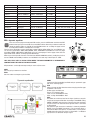
To protect a speaker from over heating you have to know some technical data:
1) The speaker power handling (PAES) measured with the AES2-1984 (r2003) standard (AES Recommended Practice - Specification of
loudspeaker components used in professional audio and sound reinforcement), usually it is indicated in the speaker technical data in
WAES. This standard is actually the best method to know the power handling capability of the speaker for a standard music program.
In case of a group of speaker connected to the same channel you have to consider the whole power handling.
2) The nominal impedance (ZNOM) of the speaker and/or the resulting nominal impedance of the group of speaker connected at the
same amplifier channel (typically 4 or 8 ohm).
3) Choose an amplifier that can drive this speaker with a nominal continuous power (PAVG or PCONTINUOUS or P(EIA 1KHz THD<1%)) higher than
the specified power handling of the speaker. Obviously this power must be delivered from the amplifier for the nominal impedance
specified. The power of the amplifier must be always higher than that of the speaker in order to avoid the signal clipping, an event
that can seriously damage or destroy a speaker
4) A typical professional amplifier has two operating modes that can be selected by a switch in the rear panel:
The first mode is at "nominal input sensitivity", which means that "full power is delivered when the input signal is XX dBu", typical
values being 0dBu or +4dBu.
The second mode is at "fixed gain", which means that the amplifier voltage gain is fixed at a specified value expressed in dB, typical
values being 26 or 32dB (GAIN).
To simplify the calculations we consider only the second case with an amplifier with a fixed gain.
Calculate the limiter setting using the following equation:
�𝑃𝑃𝐴𝐴𝐴𝐴𝐴𝐴 × 𝑍𝑍𝑁𝑁𝑁𝑁𝑁𝑁
𝐿𝐿𝐿𝐿𝐿𝐿𝐿𝐿𝐿𝐿(𝑑𝑑𝑑𝑑𝑑𝑑) = 20 × log10 �
� − 𝐺𝐺𝐺𝐺𝐺𝐺𝐺𝐺
0.775
�𝑃𝑃𝐴𝐴𝐴𝐴𝐴𝐴 × 𝑍𝑍𝑁𝑁𝑁𝑁𝑁𝑁
� − 𝐺𝐺𝐺𝐺𝐺𝐺𝐺𝐺
𝐿𝐿𝐿𝐿𝐿𝐿𝐿𝐿𝐿𝐿(𝑑𝑑𝑑𝑑𝑑𝑑) = 20 × log10 �
0.775
300 W
As example we presume to have a speaker with the following data:
P =×
4 Z = 4 OHM
√300
𝐿𝐿𝐿𝐿𝐿𝐿𝐿𝐿𝐿𝐿(𝑑𝑑𝑑𝑑𝑑𝑑) = 20 × log10 �
� – 32 = +1 𝑑𝑑𝑑𝑑𝑑𝑑
0.775
√300 × 4
𝐿𝐿𝐿𝐿𝐿𝐿𝐿𝐿𝐿𝐿(𝑑𝑑𝑑𝑑𝑑𝑑) = 20 × log10 �
� – 32 = +1 𝑑𝑑𝑑𝑑𝑑𝑑
0.775
AES
NOM
So we choose an amplifier capable of 500 W with a load of 4 ohm for channel with a fixed gain of: GAIN = 32 dB
Please note that in some cases you can obtain a negative result.
SOME TIPS
• To protect the high frequency drivers from dangerous feedbacks in live environments we suggest to set the limiter 3 dB under the
calculated value.
• In some speaker systems you can note that the low-mid frequencies are limited before the high-mid frequencies. This can be due
to the fact that the program reproduced is more rich in low frequencies (which usually have a higher energy contents) than in high
frequencies, so the LF limiter is activated before and more often than the HF limiter. In this cases, the system sound can become very
harsh and to restore a natural sound you'll need to set the HF driver limiter some dB under the calculated value (usually 3 - 6 dB).
• Often using bridged amplifier you have to add 6 dB to your amplifier GAIN: see the amplifier manual.
26
SPL MANAGEMENT
PC260 has a unique feature called Sound Pressure Level Management, specifically designed for the use of the processor in FIXED
INSTALLATIONS. Using the SPLM the user can program changes in the settings of the audio system at a specified time in a specified
day of the week. The PC260 has an internal clock that keeps the time also if the unit is turned off, so when an SPLM program is
activated, the event programmed can be performed in real time.
The SPLM has 4 programs that can be used, for example, for different periods of the year.
Each program includes 16 events that can be selected among the following:
- Mute, Level, Threshold (DYN processor) adjustment on the INPUTS (single A or B, ALL)
- Mute, Level, Threshold (DYN processor) adjustment on the OUTPUTS (single 1 to 4 or 1 to 6, ALL)
- PRESET recall
Press the SPLM button to access the first page of the Sound Pressure Level Management, where
you can select the PROGRAM to edit or activate using the DATA knob (rotate + press).
In the following page use again the DATA knob (rotate + press) for choosing between EDIT or
ACTIVATE
If you choose EDIT, in the following page you have to enter the name of the
program: type the name using the DATA knob, then press SPLM to confirm it.
Use PG UP or PG DW to scroll between the events and the DATA knob for setting
the time and choosing the event to program. Finally tick the ENABLE flag (note
that unticked flags disable the event of the list).
If you choose ACTIVATE, the sequence of programmed events will be activated
according to the real time clock and to the time set for the events.
For activating the SPLM, the processor must be set in TOTAL LOCK status,
so in the following page you will be required to enter a password. Once the
password the PC260 will be put in TOTAL LOCK status and the SPLM sequence
will be activated.
27
RTA
The PC260 processor has a built in 1/3 octave Real Time Analyzer, which is a useful tool for measuring the acoustic response of the
sound system in order to make the proper EQ adjustments.
This RTA is not a precise measurement system such as dedicated computer software, but it can be used to get a general overview of
the system's response in a not too much reverberant and noisy enviroment.
When you use an acoustic measurement gear remember always the following tips:
• You have to fix the system not a line on the screen.
• With the equalization you cannot correct a bad room acoustic: if the venue is too reverberant at some frequencies it remains
reverberant also after the equalization.
• Always listen with your hear, do not blindfold trust any measurement.
• A good audio system placed in a good enviroment requires only little adjustments, usually by cutting few dBs in some frequency
ranges. If you have to set exaggerated EQ, you probably have a noticeable acoustic problem and EQ'ing could not be the right cure.
• Acoustics measurements are not a simple issue and require a specific knowledge.
To make a RTA measurement you must have some additional equipment:
• A measurement microphone: for this kind of measurement you don't need the best microphone avilable, a simple and economic
class 2 microphone is sufficient.
• A microphone stand.
• A XLR balanced cable (the lenght depends by the distance between the measurement mic and the PC260).
• A track with a pink noise record: pink noise is a special random noise where each octave carries an equal amount of noise power.
• A track or a selection of tracks of your preferred songs.
Connect the mic to the RTA MIC INPUT then place the mic on the stand at the centre of the venue. The distance between the speakers
and the measurement mic must be no longer than 10 meters (30 ft), otherwise you may not have a sufficient signal to noise ratio.
1) Play the pink noise on the audio system.
2) Turn up the volume to a reasonable level, avoiding to compress/limit any input/output in the PC260 (see the LED
indicators on the front panel).
3) Press RTA, then using the DIAL knob adjust the mic input level to have a sufficient signal across the mid line. If the
audio system is right tuned, the RTA is aproximately linear with some bars above and some bars below the mid line.
4) If a noticeable misalignment is displayed you can try to adjust it using the input GEQ or PEQ.
5) After some adjustments you may be obtain a more linear RTA.
Often if the misalignement is under the 400 Hz and you cannot obtain any
adjustment, try to move the MIC in another position.
before EQ'ing
6) Once you are satisfied, turn off the pink noise and play you favorite songs.
By turning on and off the EQ section, listen the differences and if necessary
adjust the EQ settings. Always remember the first tip:
You have to fix the system not a line on the screen.
after EQ'ing
28
TYPICAL CONFIGURATIONS
As explained in the ROUTING section, the signal routing from input channels A & B is completely free and and can be assigned to any
output channel. The following figures show some configuration example:
PC260 2 x 3 xover (advanced live or disco system)
L
high
R
L
high mid
R
mid
L
low
R
low
L
amplifier rack
input
1 amp3
2
1 amp2
2
1 amp1
2
L
R
output
1
HIGH sat out 2
1
MID sat out 2
LOW sub out 1
2
L
L
R
R
L
R
PC260 2 x 2 xover + 1 zone (advanced live or disco pub system)
L
R
high low
R
full
R
L
high low
input
1 amp3
2
1 amp2
2
1 amp1
2
L
full
L
amplifier rack
LOUNGE BAR SYSTEM
L
R
output
1
HIGH sat out 2
1
LOW sub out 2
FULL aux out 1
2
L
L
R
R
L
R
DANCE FLOOR MAIN SYSTEM
29
PRONET NETWORK
The PRONET philosophy
PRONET software has been designed by Proel’s Research & Development Department to easily control a single unit or a network of
devices, like active loudspeakers or speaker processors, equipped with the C-AUDIO CORE digital processing platform.
PRONET has been developed in collaboration with sound engineers and sound designers, in order to offer an "easy-to-use" tool to
setup and manage your audio system. With PRONET you can visualize signal levels, monitor internal status and edit all the parameters
of each connected device.
Download the PRONET app from the PROEL website at http://www.proel.com clicking on support / download section.
Connecting devices
To configure a single processor like PC260 you can use a direct connection from your computer to the front panel USB port:
PC260 has both a USB and a network connection, so you'll need to select which connection you want to use in the SETUP menu (see
above in this manual). If you want to use the network connection, the PROEL USB2CAN converter is needed.
The first time you connect a Processor device with a USB cable or with USB2CAN converter, Windows O.S. will ask you to install
the driver files, which you can find in the Driver folder within the Pronet application folder (by default is C:\Program Files\Proel\
Pronet\Driver, or if you changed it <your path>\Driver). Please refer also to "Installation" and "Drivers" paragraphs in the Pronet
documentation.
Connecting devices to a PRONET NETWORK
For managing complex setups including multiple units of active speakers and processors, PROEL engineers have developed a
networking system based on a robust, reliable and fast communication protocol called CANBUS.
The devices in a PRONET NETWORK are connected toghether with a "linear bus topology". A PROEL USB2CAN CONVERTER is needed
for connecting the network to the USB port of the PC running the PRONET application. The USB2CAN CONVERTER is connected to
the newtork input of the first device, the network output of the first device is connected to the input of the second and so on. For the
network connections simple RJ45 cat.5 (or cat.6) ethernet cables can be used.
The beginning and the end of a PRONET NETWORK must be terminated. One side is terminated by the USB2CAN
converter, the other side must be terminated pressing the TERMINATE switch on the last device. All devices between
these two points must have the TERMINATE switch lifted.
PC NOTEBOOK
USB2CAN
STATUS
CONVERTER
USB2CAN
00001
5V --- 200mA
USB2CAN
CODE:
S/N:
RATINGS:
RoHS COMPLIANT
MADE IN ITALY
USB 2.0 port
last device
PC260
do not
pressed
pressed
network
PC260
do not
pressed
30
Assign the ID number
To work properly in a PRONET NETWORK each connected device must have a unique Identifier Number, called ID. By default the PC
controller has ID=0 and there can be only one PC controller in a network. Every other device connected must have its own unique ID
equal or greater than 1: in the network cannot exist two devices with the same ID.
An ID number is assigned automatically to each devices when they are turned on for the first time connected to a network.
In order to correctly assign a new available ID to each device for working properly in a Pronet network, follow these instructions:
1. Switch off all the devices.
2. Connect them correctly to the network cables.
3. "TERMINATE" the lastest device in the network connection.
4. Switch on the first device in the network connection.
- If it is a loudspeaker processor keep pressed "RTA" button on the front panel while switching on.
- If it is an active loudspeaker keep pressed "Preset" button on the back panel while switching on.
5. Leaving the previous device switched on, repeat the previous operation on the next device,
until the latest device is turned on.
The "Assign ID" procedure for a device makes the internal network controller to perform two operations: reset the current ID; search
the first free ID in the network, starting from ID=1.
If no other devices are connected (and powered on), the controller assume ID=1, that is the first free ID, otherwise it searches the
next one left free.
These operations ensure that every device has it's own unique ID, if you need to add a new device to the network you simply repeat
the operation of step 5.
Every device maintains its ID also when it is turned-off, because the identifier is stored in the internal memory and it
is cleared only by another "Assign ID" step, as explained above. This means that if your network is made always of the
same devices the assigning ID procedure must be executed only the first time the system is turned on.
Note 1: If you add a new device as the last device in a Pronet network you have to re-set correctly the termination.
Note 2: Each device is issued from the PROEL factory has ID=1. Often also a device that returns from a technical assistance center
will be ID=1.
Note 3: Into a Pronet network the IDs don't need to be sequential, they only must be unique. An example of this happen when you
remove or power-off a device correctly assigned and already working into a network, there is a gap in the IDs sequence but it isn't a
problem. Another example is when you add a new device with ID already assigned in different Pronet network, but different from any
other ID already assigned in the network.
When working without a PC controller, you can still connect together a subsystem of active loudspeakers (satellities or subwoofers):
with this kind of network, when you change a preset in one device you also change the same preset in each connected device of the
same type (the same model).
Working with PRONET
PRONET application constantly checks the status of connected devices, if one of them loses the connection (network discontinuity,
power shut down and so on), its label in the device tree list is highlighted with a red background colour.
PRONET application detect automatically if a disconnected device is re-actived, in this case PRONET re-load the device’s data and
the label in the device tree list changes to a green background colour.
PRONET can also detect automatically if a new device has been connected. If the new device’s ID is a valid one then PRONET loads
its datas and a new label appears in the device tree list. If the ID is not valid, because there is another device with the same ID in the
network, no new device appears in the tree list or “ID conflict” / "Wrong Type" message appears in the device tree list.
In this case turn off the devices then turn on it as described in the ASSIGN ID section at the point 5, then force a new scan of the
network using the “rescan” button on the PRONET application (also available in Menu/Connection/Rescan).
A rescan operation clears the device tree list and searches again the connected devices.
More detailed instructions about PRONET application can be found in the included / on line documentation.
31
USB2CAN converter
To work with a Pronet network you need a USB2CAN converter that converts the USB data flow into the CAN bus. The USB2CAN
converter needs to be connected to a USB 2.0 full speed port.
USB2CAN Features:
ARM7 microcontroller inside
Galvanic isolation 500 V
Voltage supply via USB bus
USB 2.0 full speed
High productivity on 1Mbit CAN bus speed
Wide CAN bus baud rate range: 10-1000 Kbit/s
Compliant with CAN specifications 2.0A (11-bit ID) and 2.0B (29-bit ID)
Firmware upgrade via bootloader
Drivers for Windows 2000, Windows XP, Windows Vista,Windows 7
To install correctly the software driver for the USB2CAN converter see "Installation" and "Drivers" paragraphs in the included or online
ducumentation.
When you connect the converter to the USB port of the PC, the LED on the top lights RED: this mean that it is powered but the converter
is not working yet.
The first time you go "online", the Pronet software application starts to control the network via the USB2CAN controller, sending and
receiving datas from connected devices. If everything is OK the LED on the top of the converter lights GREEN indicating the activities
on the network.
If there is a problem with the software driver, with network bus or there is a problem on the converter the LED flashes red and/or green.
STATUS LED
operation
RED/GREEN toggling
PC USB driver isn't installed
RED steady
converter is not working
GREEN steady
converter is working
GREEN blinking slow
there is a problem in the bus
GREEN blinking fast
there is a problem in the bus
RED blinking slow
there is a problem in the bus
RED and GREEN steady
Service mode
32
CLOCK BATTERY REPLACEMENT
The internal clock is equipped with a long time discharge LITHIUM battery, in
order to keep running also when the unti is switched off. The discharge time
may be more than 2 years and the battery status is showed on the display. In the
figure on the left the bar inside the battery shows that it is completely charge.
When it will be completely empty the battery must be replaced as follow:
0. USE A CR2477 LITHIUM BATTERY FOR REPLACEMENT.
1. DISCONNECT THE PC260 FROM THE MAINS LINE OUTLET.
2. OPEN THE PC260 REMOVING THE SCREWS SHOWN IN THE FIGURE:
3. LOCATE THE BATTERY (IT IS THE SILVER BOTTON ON THE REAR SIDE).
4. REMOVE THE OLD BATTERY (USE A PLASTIC TOOL TO LIFT UP THE POSITIVE CONTACT).
5. PLACE THE NEW BATTERY INSTEAD THE OLD ONE:
IMPORTANT AT THIS POINT ALWAYS FOLLOW CAREFULLY THESE TWO STEPS IN ORDER TO AVOID ABNORMAL CONSUMPTION OF
THE BATTERY
6. SWITCH ON THE PC260 AND WAIT SOME SECONDS UNTIL THE DISPLAY SHOWS THE INITIAL PAGE.
7. SWITCH OFF, WAIT 2 SECONDS THEN SWITCH ON AGAIN.
BE CAREFUL
DANGER OF EXPLOSION IF BATTERY IS INCORRECTLY REPLACED.
REPLACE ONLY WITH SAME TYPE: CR 2477 LITHIUM MANGANESE DIOXIDE BATTERY.
The battery contains Perchlorate Material – special handling may apply, it should not be disposed with other household wastes at
the end of its working life. To prevent possible harm to the enviroment or human health from uncontrolled waste disposal, please separate
this from other types of wastes and recycle it.
33
TECHNICAL SPECIFICATION
Input Section
Inputs
Input Impedance
Maximum Input Level
Input gain
Input Connectors
Digital Input
2 electronically balanced
> 10 kohm
+20 dBu (+26 dBu with -6dB pad)
+6 dB to –30 dB in 0,2 dB steps
XLR F - XLR M to link
AES/EBU (32 - 96 KHz sample rate converter inside)
Output Section
Outputs
Maximum Output Level
Output Gain
Output Connectors
6
+20 dBu
+15 dB to –30 dB in 0,2 dB steps and mute
XLR M
Crossover Filters
Slopes
Type
6 / 12 / 18 / 24 / 48 dB per octave
Bessel / Butterworth / Linkwitz-Riley
Delays
Max Delay time
600 ms on ALL In and Out
Min Delay Step
21 us
Parametric EQ filters
Maximum number of filters
5 per input / 5 per output
EQ Type
Parametric, Notch, Shelf, Bandpass, res. hp/lp, Allpass
EQ Gain
+15 dB to -15 dB in 0,2 dB steps
Q (bandwidth)
0,4 to 28,85 (3 to 0,05,1/20 oct. steps)
EQ freq
15,6 Hz – 22,62 kHz (1/20 oct. steps)
Dynamic EQ filters
Maximum number of filters
Parameters
3 per input
EQ Param., Shelf 6 / Freq. / Gain / Thre. / Time / Below-Above
Graphic EQ
EQ Type
28 band 1/3 oct.
EQ freq
31,5Hz - 16kHz 1/3 oct.
EQ Gain
+12 dB to -12 dB in 0,2 dB steps
EXTRA FEATURES
RTA range
RTA MIC input
SPLM
20Hz-20kHz 1/3oct.
15V phantom power
4 scene /16 events for each scene
General
AD/DA conversion
AD/DA latency
24 bit
1,68 ms (analogue in – analogue out @ 48 KHz)
Sampling frequency
48 kHz
Internal processing
40 bit floating point
Frequency response
Dynamic range
Distortion (THD)
Display
Input / Output meters
Remote control
Dimensions
Weight
AC Power
Consumption
34
±0,5 dB 20 Hz-20 kHz
>110 dB 20 H-0 kHz unweighted
< 0,015% @ 1kHz, +18dBu
192x32 LCD Graphic Display
4 LED
USB, RJ45 PRONET network
44 x 482 x 295 mm
4,1 kg (9 lb)
100 to 240V ±15% @ 50/60 Hz
35 VA
Appendix A (signal to power)
With the following table is possible to set the limiters without using a scientific calculator. To explain how to use it we make an
example.
You have two loudspeaker with this data:
Power handling: 250 Waes
Nominal Impedance: 8 ohm
and an amplifier capable of 600 Wcontinuos at 4 ohm with a FIXED GAIN of 32 dB, so
the loudspeakers are arranged in parallel resulting a power handling of 500 Waes at 4 ohm,
you have to choose the 4 ohm column in the fixed gain = 32 dB, scroll the values until reach 475, it is the value more close and slighlty
less to 500 Waes, then scroll the row at right and note the +3 dBu value, this is the value of the input signal that delivers 475 W to your
loudspeaker, you have to set the limiter to this value.
Note: to avoid clipping the amplifier must be always capable to deliver a power greater than the power you have to limit.
Input Signal
dBu
+21
+20
+19
+18
+17
+16
+15
+14
+13
+12
+11
+10
+9
+8
+7
+6
+5
+4
+3
+2
+1
+0
‐1
‐2
‐3
‐4
‐5
‐6
Signal references
dBv
Vrms
+18,79
8,696
+17,79
7,750
+16,79
6,907
+15,79
6,156
+14,79
5,487
+13,79
4,890
+12,79
4,358
+11,79
3,884
+10,79
3,462
+9,79
3,085
+8,79
2,750
+7,79
2,451
+6,79
2,184
+5,79
1,947
+4,79
1,735
+3,79
1,546
+2,79
1,378
+1,79
1,228
+0,79
1,095
‐0,21
0,976
‐1,21
0,870
‐2,21
0,775
‐3,21
0,691
‐4,21
0,616
‐5,21
0,549
‐6,21
0,489
‐7,21
0,436
‐8,21
0,388
INPUT SIGNAL to OUTPUT POWER CONVERSION TABLE
Power Output
Fixed amp gain = 26 dB
Fixed amp gain = 32 dB
Impedance
Impedance
2 ohm
4 ohm
8 ohm
16 ohm
2 ohm
4 ohm
8 ohm
16 ohm
7526
3763
1881
7490
5978
2989
1494
5950
9497
4748
2374
1187
9452
4726
7544
3772
1886
943
15016
7508
3754
5992
2996
1498
749
11927
5964
2982
4760
2380
1190
595
9474
4737
2369
3781
1890
945
473
7526
3763
1881
3003
1502
751
375
5978
2989
1494
2385
1193
596
298
9497
4748
2374
1187
1895
947
474
237
7544
3772
1886
943
1505
753
376
188
5992
2996
1498
749
1196
598
299
149
4760
2380
1190
595
950
475
237
119
3781
1890
945
473
754
377
189
94
3003
1502
751
375
599
300
150
75
2385
1193
596
298
476
238
119
59
1895
947
474
237
378
189
95
47
1505
753
376
188
300
150
75
38
1196
598
299
149
239
119
60
30
950
475
237
119
189
95
47
24
754
377
189
94
151
75
38
19
599
300
150
75
120
60
30
15
476
238
119
59
95
47
24
12
378
189
95
47
75
38
19
9
300
150
75
38
60
30
15
7
239
119
60
30
48
24
12
6
189
95
47
24
38
19
9
5
151
75
38
19
30
15
8
4
120
60
30
15
35
PROEL S.p.A.
(World Headquarters - Factory)
Via alla Ruenia, 37/43
64027 Sant’Omero (TE) - ITALY
Tel. +39 0861 81241
Fax +39 0861 887862
REV. 30/13 CODE 96MAN0040
www.proel.com