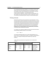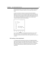
1
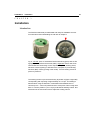
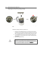
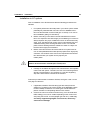
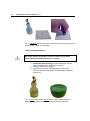
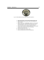
Antec Industrieweg 12 2382 NV Zoeterwoude The Netherlands SenCellTM Electrochemical Flow cell User manual 116.0010, Edition 1, 2012 T +31 71 5813333 | F +31 71 5813334 | [email protected] | www.myantec.com Antec is an ISO 9001:2008 certified company. Copyright ©2012, Antec, The Netherlands. Contents of this publication may not be reproduced in any form or by any means (including electronic storage and retrieval or translation into a foreign language) without prior agreement and written consent from the copyright of the owner. The information contained in this document is subject to change without notice. ROXY, ALEXYS, DECADE, DECADE II, INTRO, Flexcell, ISAAC, HyREF, SenCell are trademarks of Antec. Whatman™ (word and device) and Whatrnan™ (word only) are trademarks of Whatman lnternational Ltd. SOLVENT IFD™ and AQUEOUS IFD™ are trademarks of Arbor Technologies, Inc. Clarity®, DataApex® are trademarks of DataApex Ltd. Microsoft® and Windows™ are trademarks of Microsoft Corporation. Excel is a registered trademark of the Microsoft Corporation. All other trademarks are the property of their respective owners. The software and the information provided herein is believed to be reliable. Antec shall not be liable for errors contained herein or for incidental or consequential damages in connection with the furnishing, performance, or use of software or this manual. All use of the software shall be entirely at the user’s own risk. INTRODUCTION 3 Symbols The following symbols are used in this guide: The warning sign denotes a hazard. It calls attention to a procedure or practice which, if not adhered to, could result in severe injury or damage or destruction of parts or all of the equipment. Do not proceed beyond a warning sign until the indicated conditions are fully understood and met. The attention sign signals relevant information. Read this information, as it might be helpful. The note sign signals additional information. It provides advice or a suggestion that may support you in using the equipment. Intended use This hardware should be used by trained laboratory personnel only with a completed degree as chemical laboratory technician or comparible vocational training. The operator should have fundamental knowledge of liquid chromatography. Use proper eye and skin protection when working with solvents. Additional safety requirements or protection may be necessary depending on the chemicals used in combination with this equipment. Make sure that you understand the hazards associated with the chemicals used and take appropriate measures with regards to safety and protection. 4 SenCell flow cell user manual, ed. 1 (U) HPLC: (Ultra) High Performance Liquid Chromatography (HPLC) is a method for separating substance mixtures, determining substances and measuring their concentration. This device is suitable for high-performance liquid chromatography. It is suitable for laboratory use, for analyzing substance mixtures that can be dissolved in a solvent or solvent mixture. Check intended use: Only use the device for applications that fall within the scope of the specified intended use. Else the protective and safety equipment of the device could fail. Laboratory use: Biochemistry/bioanalytical analyses Chiral analyses Food analyses Pharmaceutical analyses Environmental analyses Clinical analyses (research purpose only) With respect to clinical analyses the device is intended for research purposes only. While clinical applications may be shown, this device is not tested by the manufacturer to comply with the In Vitro Diagnostics Directive. Laboratory regulations Observe national and international regulations pertaining to laboratory work! For example: Good Laboratory Practice (GLP) of the American Food & Drug Administration For development of methods and validation of devices: Protocol for the Adoption of Analytical Methods in the Clinical Chemistry Laboratory, American Journal of Medical Technology, 44, 1, pages 30–37 (1978) Accident prevention regulations published by the accident insurance companies for laboratory work INTRODUCTION 5 Solvents Organic solvents are highly flammable. Since capillaries can detach from their screw fittings and allow solvent to escape, it is prohibited to have any open flames near the analytical system! Regularly check for leaks and clogged LC tubing and connections. Test back pressure without column. Do not close or block drains or outlets. Do not allow flammable and/or toxic solvents to accumulate. Follow a regulated, approved waste disposal program. Never dispose of such products through the municipal sewage system. Toxicity: Organic solvents are toxic above a certain concentration. Ensure that work areas are always well-ventilated! Wear protective gloves, safety glasses and other relevant protective clothing when working on the device! 6 SenCell flow cell user manual, ed. 1 INTRODUCTION Table of contents Table of contents I N T R O D U C T I O N Symbols 3 Intended use 3 Laboratory regulations 4 Solvents 5 Table of contents 7 The electrochemical flow cell 9 Introduction 9 Three-electrode configuration 10 Working electrode 11 Detection limit 12 Cell working volume adjustment 13 Reference electrodes 17 ISAAC reference electrode 17 Salt bridge Ag/AgCl reference electrode 19 HyREF reference electrode 19 Installation 21 Introduction 21 Adjusting the SenCell working volume 22 Installation in LC system 23 Maintenance 27 Assembling/Disassembling the Cell 27 HyREF 29 ISAAC 29 Polishing 29 Coating with ISAAC solution 30 Ag/AgCl salt bridge 31 Saturation and air bubbles 31 Material 32 Procedure 32 Maintenance of the cotton wool frit 33 Working electrode 34 Polishing 34 Specifications 37 Part list 39 Index 41 7 8 SenCell flow cell user manual, ed. 1 CHAPTER 1 The electrochemical flow cell C H A P T E R 9 1 The electrochemical flow cell Introduction TM Congratulations on your purchase of the SenCell , a new electrochemical flowcell for (U)HPLC with ECD. The SenCell has several unique features (Patent Pending) like a stepless adjustable working volume (spacerless concept) and toolless assembly. The SenCell is available with a glassy carbon working electrode (WE). The SenCell design eliminates the use of plastic/metal spacers. The working volume of the electrochemical cell can be stepless adjusted without opening the cell by means of a special key, allowing easy optimization of the detection sensitivity for any LC application. The working volume can be adjusted between roughly 0 – 300 nL (based on a 2 mm diameter WE). As a standard, the salt bridge Ag/AgCl reference electrode is advised. For special applications the HyREF™ reference electrode is available. A third reference electrode is the in situ Ag/AgCl (ISAAC™). Fig. 1. Left side: assembled SenCell electrochemical flow cell with ISAAC inlet block (green). The upper part, the inlet block, is separated from the working electrode block. Right side: SenCell WE block. . The SenCell has been developed for ultra-trace analysis in standard, microbore and capillary LC-EC. After extensive testing it was established that the confined wall-jet configuration gave the very best results. In addition it was found that the electrode materials quality and the finishing of the electrodes in the flow cell are decisive factors for the performance of an EC detector. While competitive designs usually deteriorate when in use, this flow 10 SenCell flow cell user manual, ed. 1 cell, by design, improves in performance. The flow cell permit unusually short stabilisation times: trace analysis within a few hours after starting up may be expected. Three-electrode configuration In the SenCell flow cell a three-electrode configuration is used (Fig. 2). The working potential is set between the working electrode (WE) and the auxiliary electrode (AUX). The AUX is kept at a precisely defined reference electrode (REF) potential by means of the so-called voltage clamp. This is an electronic feedback circuit that compensates for polarisation effects at the electrodes. At the WE, which is kept at virtual ground, the electrochemical reaction takes place, i.e. electrons are transferred at the WE. This results in an electrical current to the I/E converter, which is a special type of operational amplifier. The output voltage can be measured by an integrator or recorder. Fig. 2. Schematic representation of an electrochemical cell with a threeelectrode configuration. Essentially, for the oxidation or reduction reaction it would be sufficient to use only two electrodes. However, the three-electrode configuration has several advantages over a two-electrode configuration. If the working potential would be applied only over an AUX versus the WE (without REF), the working potential would continuously change due to polarisation effects at the electrodes, resulting in highly unstable working conditions. CHAPTER 1 The electrochemical flow cell 11 If the working potential would be applied only over the REF versus the WE (without AUX), the working potential would be very well defined. However, the potential of a REF is only well defined if the current drawn is extremely low (pico-amperes) resulting in a very limited dynamic range. A three-electrode configuration, combines the best of both electrodes. The REF stabilises the working potential and the AUX can supply high currents. This results in the tremendous dynamic range of a three-electrode system. Working electrode Electrochemical detection puts high demands on the WE material. The WE should be made of a (electro-)chemically inert material. Furthermore, to avoid an irregular flow profile over the electrode, it should have a very well defined surface. Finally, it is important that the analyte of interest can be oxidised (or reduced) with favourable I/E characteristics. This in fact means that a high signal must be obtained at a low working potential. For most applications glassy carbon will be the WE material of choice. The SenCell is currently available with 2 mm diameter Glassy Carbon electrode only. Under certain circumstances other materials are favourable. For example, for the analysis of iodide a silver WE can be used. At the silver WE the following oxidation reaction occurs for iodide: - - Ag + I AgI + e This reaction already takes place at a very low working potential (1 mV !), which results in an extremely high selectivity. This allows the determination of iodide in urine samples to take place almost without any sample pretreatment. Table I. Working potential limits and application area for different WE materials. WE material Glassy carbon Gold Platinum Silver Copper potential limits (V) alkaline acidic -1.50 -1.25 -0.90 -1.20 - -0.80 -0.35 -0.20 -0.55 - +0.60 +0.75 +0.65 +0.10 +0.60 major application +1.30 +1.10 +1.30 +0.40 - catecholamines carbohydrates alcohols, glycols halides, cyanide amino acids, carbohydrates 12 SenCell flow cell user manual, ed. 1 Another consideration in choosing a WE is the oxidation or reduction of mobile phase constituents or WE material, that occurs when the potential exceeds the limits as given in Table I. At high positive working potentials the water in the mobile phase electrolyses and results in an strong increase of the background current and noise. Formation of metal oxides, resulting in an increase in background current is a limiting factor for metal electrodes. Glassy carbon and platinum have the highest positive potential limits and are therefore often used in oxidative ECD. For negative potentials the use of platinum electrodes is limited by the ease of reducing hydrogen ions to hydrogen gas. Detection limit One of the most important parameters used to characterise the performance of a detection system is the signal-to-noise ratio (S/N ratio) from which the concentration detection limit is derived. It enables objective comparison not only between different electrochemical detectors but also between complete analytical methods irrespective what detection system is used. Table II. LC-EC conditions for analysis of norepinephrine. column flow rate mobile phase sample temperature Cell E cell Icell ODS-2, 3 µm, 100 x 4.6 mm 1.0 ml/min H3PO4 50 mM, citric acid 50 mM, 20 mg/l EDTA, 100 mg/l octane sulphonic acid (OSA), pH=3.1 with KOH, 5% methanol 1.0 µmol/l norepinephrine, 20 µl injection o 30 C Flow cell with 3 mm GC WE, SB REF with 50 µm spacer 800 mV (vs. Ag/AgCl, filled with saturated KCl) ca. 3 nA In literature several ways are described to determined the detection limit. In principle, it does not matter which definition of detection limit is used, as long as the definition is precisely described. In this manual the concentration detection limit (cLOD) for a certain compound is defined as the analyte concentration that results in a signal that is 3 times the standard deviation of the noise: c LOD = 3 noise signal cA where sigma-noise is 0.2 x peak-to-peak noise and cA is the concentration of analyte injected. In Fig. 3 a typical S/N ratio for a flow cell with 2.74 mm WE is shown. In this example the concentration detection limit for norepinephrine based on three CHAPTER 1 The electrochemical flow cell times the sigma-noise is 11 pmol/L (see Table II for conditions). Expressing the performance of a detection system by only the peak height makes no sense. A system can easily be changed in a way that a larger peak height is obtained. However, if the noise increases similarly, it has the same effect as switching a recorder to a higher sensitivity: peaks appear higher but the S/N ratio is the same. Expressing the limit of detection in an absolute amount (i.e. in picomoles) without mentioning the injection volume, makes a good comparison between different systems difficult. Fig. 3. Example S/N ratio for norepinephrine (peak height: 80 nA, peak-topeak noise: 1.5 pA). The amount injected is 20 pmol (1.0 µmol/l). The concentration detection limit based on three times sigma-noise in this case is 11 pmol/l. Cell working volume adjustment In a traditional electrochemical flow cell which uses metal/plastic gaskets (spacers) the thickness of the gasket affects the linear flow velocity in the cell. With a thinner gasket the cell working volume is decreased, resulting in a higher linear flow velocity. For example the working volume of a cell with a 2 mm diameter electrode with 25 and 50 µm spacer is 80 nL and 160 nL, respectively. 13 14 SenCell flow cell user manual, ed. 1 The signal increases with thinner spacers while the noise remains more or less constant, which can lead to improvement of the detection sensitivity (signal-to-noise ratio). Several authors have described the relation between the layer thickness (i.e. spacer thickness) in a thin layer flow cell and the -2/3 measured current (S) as S = k b where b is the spacer thickness and k a constant. The SenCell design eliminates the use of polymeric or metal gaskets. The working volume of the electrochemical cell can be stepless adjusted without opening the cell using the supplied adjustment key (p/n 116.1400). This allows easy optimization of the cell working volume and thus detection sensitivity (signal-to-noise ratio) for any LC application. Fig. 4. Example chromatograms of 100 nM standard of catecholamines in 10 mM HAc recorded with the Sencell spacing adjustment set to position 3 and 0.5, corresponding with an approximate spacing setting of 100 µm and 12 µm respectively. In figure 4 an example is shown to demonstrate the effect of cell working volume on signal. In figure 5 the peak height (normalized) as a function of spacing is shown for Dopamine based on the data from the example shown in figure 4. CHAPTER 1 The electrochemical flow cell Fig. 5. Normalized Peak height of Dopamine as a function of spacing setting (red curve) based on chromatograms recorded with a 100 nM standard of catecholamines in 10 mM HAc with a SenCell. The dotted curve is a simulated curve based on the Cotrell equation (Lit ref F.G. Cottrell, Z. Phys. Chem 42 (1903) 385). Decreasing the spacing/working volume is limited by an increased pressure drop over the flow cell which eventually will lead to an obstruction of the flow. The onset is typically characterized by an increased noise level and the rise of the system back pressure. Applying small working volume settings should be done with great care, it may cause excessive pressure built-up over the flow cell, excessive baseline noise and may damage the cell. In any case DO NOT OPERATE THE CELL AT POSITION 0. This is illustrated in figure 6. It is evident that the noise remains relatively constant as a function of spacing, but at a spacing of approximately 6 µm a significant increase in noise is observed accompanied with a rise in system pressure due to a restriction build over the cell. So in this example setting the cell spacing less than approximately 12 µm is not advisable. 15 SenCell flow cell user manual, ed. 1 Pump pulsations & pressure rise [pA] 5 3.0 6 um 2.5 2.0 12 um 0 Current Unf iltered noise (pA) 16 1.5 25 um -5 50 um 1.0 100 um 0.5 -10 0.0 0 20 40 60 80 100 9 10 11 12 Time 13 14 15 16 [min.] Space setting SenCell (µm) Fig. 6. Left side: ASTM noise values as a function of cell spacing. Right side: Noise traces as a function of cell spacing. SenCell spacing position 3 corresponds with approximately 100 ± 10 µm. The spacings used with this particular SenCell under test in this experiment were determined using a stylus profilometer. So optimization of the cell working volume is focused on finding the right balance between signal height and noise level for your SenCell, under your specific LC-EC condition. Optimization can be achieved by decreasing the cell spacing in small steps in a systematic way and evaluating the baseline noise and peak height of the analytes of interest till you find the optimal Signal-to-Noise ratio. Note that with LC applications using larger ID columns in combination with higher flow rates the minimum spacing which can be used will be larger. Inexperienced users are advised to use the factory pre-set cell working volumes (position 1 or 2) with their SenCell. See chapter 3 installation. CHAPTER 2 Reference electrodes C H A P T E R 17 2 Reference electrodes The SenCell is available with an ISAAC (in situ Ag/AgCl) reference electrode, a salt bridge Ag/AgCl reference electrode and a HyREF reference electrode. ISAAC reference electrode The ISAAC reference electrode is in direct contact with the mobile phase which contains chloride ions. The chloride concentration determines the potential, therefore each time a fresh mobile phase is prepared it should contain exactly the same concentration of chloride ions. The standard electrode potential of the Ag/AgCl electrode (in 1.0 mol/l Cl 0 solution) for the following half-reaction is defined as E : - - AgCl(s) + e <=> Ag(s) + Cl 0 E = 0.222 V The potential of the REF is dependent from the chloride concentration as described by the following equation: Ecell = E0AgCl - RT ln [Cl- ] F -1 -1 where R is the gas constant (8.314 Jmol K ), T is the absolute temperature -1 (293 K) and F is the Faraday constant (96485 Cmol ). The potential of the ISAAC at 2 mmol/l KCl is 379 mV ( Table III). The potential difference (dE) between the saturated KCl Ag/AgCl reference electrode and the ISAAC is 189 mV. If an application is running at 800 mV (vs. Ag/AgCl with sat’d KCl), the potential setting using the ISAAC should be 611 mV (vs. Ag/AgCl in 2mmol/l KCl). 18 SenCell flow cell user manual, ed. 1 Fig. 7. Dependence of the Ag/AgCl REF potential on the chloride concentration. Table III. Potential of the Ag/AgCl reference electrode, dE is the potential difference with EAg/AgCl in saturated KCl. - Cl (mmol/l) 3500 2500 1500 500 100 20 10 8.0 6.0 4.0 2.0 1.0 0.5 E Ag/AgCl (mV) 190 199 212 240 280 321 338 344 351 361 379 396 414 dE (mV) 0 8 21 49 90 130 148 154 161 171 189 206 224 The addition of chloride to the mobile phase has a few restrictions. For example, the ISAAC is not recommended at a high working potential (> 1.2 V vs. Ag/AgCl in 2 mmol/l KCl) because Cl is oxidised and contributes to the background current. In ion chromatography the addition of Cl may lead to undesired chromatographic changes. In case of a silver working electrode, the addition of Cl to the mobile phase will cause formation of an AgCl coating on the working electrode leading to inactivation. At high pH or high modifier concentrations the ISAAC is less suitable and a HyREF is recommended. CHAPTER 2 Reference electrodes Fig. 8. Schematic representation of the Ag/AgCl reference electrode. Salt bridge Ag/AgCl reference electrode The reference electrode of the Ag/AgCl type with salt bridge consists of a silver rod, coated with solid AgCl, immersed in a solution of saturated KCl, containing KCl crystals. Electrical contact with the other electrodes in the flow cell is made through a salt bridge consisting of a wetted cotton wool frit, which is electrically conducting and slows down leakage of KCl. This REF for the SenCell is factory filled with KCl. For certain applications another chloride salt is to be preferred. In case of perchlorate containing mobile phases, sodium chloride is mandatory, because potassium perchlorate precipitates and will clog the cotton wool frit. At high modifier percentages, the REF must be filled with lithium chloride for similar reasons. HyREF reference electrode The HyREF is a hydrogen reference electrode, its potential depends on the pH of the mobile phase. The HyREF is fully comparable with the standard Ag/AgCl REF as to baseline stability and S/N ratio. The HyREF is more userfriendly and in principle this REF is completely free of maintenance. Trapping of air bubbles like in the salt bridge Ag/AgCl type is impossible because of the absence of a salt bridge. Consequently, refilling the REF with saturated KCl is not longer required. Due to the absence of a salt bridge and its inertness, the HyREF is an excellent alternative for the Ag/AgCl REF, 19 20 SenCell flow cell user manual, ed. 1 especially in case of high modifier concentrations (i.e. analysis of fat-soluble vitamins) or high pH (analysis of carbohydrates, PAD). Depending on the pH of the mobile phase, the potential setting of the working electrode vs. the HyREF may differ significantly compared to Ag/AgCl. I/E curves show a shift of more than 200 mV at pH 3.1 (e.g. catecholamines), no shift appears at pH 12 (e.g. PAD of carbohydrates). Therefore, it is advisable first to construct a hydrodynamic (or scanning) voltammogram when using the HyREF. In Table IV the potential of the HyREF is measured against the Ag/AgCl (in sat'd KCl) electrode at different pH values. Table IV. Measured cell potential (HyREF - Ag/AgCl) versus pH. PH EHyREF - Ag/AgCl (mV) 3.3 6.2 7.5 11.8 232 130 90 0 So, if an Ag/AgCl REF is replaced by a HyREF, the pH effect must be taken into account ( Table IV). The pH vs. voltage relation is described by: EHyREF = EAg/AgCl - 328 + 29.9 pH (1) For example: a working potential of 800 mV (vs. Ag/AgCl with sat’d KCl) at pH 3, has to be changed to: EHyREF = 800 - 328 + 29.9*3 = 561.7 mV (vs. HyREF) CHAPTER 3 Installation C H A P T E R 3 Installation Introduction The SenCell is delivered pre-assembled and ready for installation and use. For instructions about assembling the cell refer to chapter 4. Fig. 9. Left side: photo of assembled SenCell inlet block (green) with In-Situ Ag/AgCl (ISAAC) reference electrode (REF). Right side: bottom side of the SenCell with the Cell working volume adjustment system, Auxiliary (AUX) electrode contact (opening on left side next to inscription ‘3’) and Working electrode (WE) contact (opening in the center). The cell working volume is preset on position 2. The working volume is pre-set at the factory at position 2 (figure 9 right side) corresponding with a spacing of approximately 50 ± 10 µm. This setting is advised when using the SenCell in combination with standard bore LC columns (2 mm – 4.6 mm ID) and flow rates > 200 µL/min. When using micro bore LC columns position 1 (25 ± 10 µm) is advised as working volume. See instructions in the next section how to adjust the working volume. 21 22 SenCell flow cell user manual, ed. 1 Adjusting the SenCell working volume Fig. 10. Adjustment of the working volume from position 2 (left side) to 1 (right side). To adjust the working volume from position 2 to 1: 1. Insert pins of the adjustment key (p/n 116.1015) in the two holes on the bottom side of the SenCell. Note that the diameter of the two pins differ. The larger diameter pin should be inserted in the AUX contact. 2. Turn the adjustment key counter clock wise until the marker on the outer metal ring is exactly aligned with the marker indicating position 1 (red arrow). 3. Remove the adjustment key. Applying small working volume settings should be done with great care, it may cause excessive pressure built-up over the flow cell, excessive baseline noise and may damage the cell. In any case DO NOT OPERATE THE CELL AT POSITION 0. CHAPTER 3 Installation Installation in LC system Prior to installation of the SenCell assure that the following precautions are followed. 1. For optimal performance all metal parts in your HPLC system should preferably be passivated with 15% nitric acid. For detailed instructions see the DECADE II user manual (p/n 171.0010) or LC connections installation guide (p/n 180.7001A). 2. Before connecting a new column read the manufacturer’s instructions. Our experience is that thorough pre-conditioning of a column is always required. Only a pre-conditioned column is electrochemically clean. If not, the background current may be unacceptably high and substantial fouling of the working electrode occurs. For reversed phase columns flushing with 50% methanol in water for 3 days at a low flow rate is highly recommended. 3. Before connection the flow cell assure that the LC system with column is well equilibrated with mobile phase prepared with high-purity chemicals. For ALEXYS users refer to the requirements documentation delivered with your system how to prepare your mobile phase. If an ISAAC™ reference electrode is used, make sure that the buffer contains at least 2 mmol/L chloride (KCl or NaCl) ions. 4. Passage of air bubbles through the flow cell will lead to unacceptable noise levels and ‘spikes’. Therefore, the use of an in-line degasser is strongly recommended. In our experience, a one-time degassing step of the HPLC buffer is almost never sufficient. Follow the procedure below to install the SenCell, see figure 3 and 4 on the next page for reference: 1. If applicable, install the SenCell clamp (p/n 250.0102A) from the shipkit (p/n 116.0202) in the center position of the DECADE II detector with a Phillips screwdriver. For other types of Antec detectors please consult the corresponding detector user manual. 2. Connect the column to the flow cell inlet using 1/16” OD small-bore PEEK tubing (0.3 mm ID or smaller depending on the column bore size) using the PCTFE 10-32 fingertight (p/n 250.1571). Use only our factory supplied fingertights in the flow cell, others may cause serious damage! 23 24 SenCell flow cell user manual, ed. 1 3. 4. 5. 6. 7. 8. Let the tubing protrude for ca. 1.5 cm from the fingertight fitting and tighten it such that the tubing is not or slightly indented by the fitting. Do not over-tighten the fingertight. Over-tightening affects the flow pattern through the tubing (turbulence) and may strongly decrease the flow cell performance. Connect 0.5 mm ID PEEK tubing to the outlet of the flow cell. Use only our factory supplied fingertights in the flow cell, others may cause serious damage! Again (see above), do not over-tighten the fingertight. Turn on the HPLC pump. Keep some tissues at hand as you probably will spill some mobile phase during this mounting procedure. For a SenCell with HyREF (black inlet block) or ISAAC reference (green inlet block): fill the flow cell, by keeping it in an angle of about 45° with the outlet (LC out) on top to force the air through the outlet. For a SenCell with Saltbridge reference (blue inlet block): fill the flow cell, by keeping it in an angle of 45° with the REF fitting on top, is best done by blocking the outlet with a finger and letting the air escape via the REF fitting. Carefully check the thread of the fitting for trapped air bubbles. When the REF fitting is completely filled with mobile phase, mount the REF while slowly releasing the outlet. Make sure not to include an air bubble! Position the flow cell in its clamp in the controller with the REF at the lower side and the outlet at the upper side. This excludes trapping of air bubbles. Connect the cell cable as shown in the figure on the next page. Red: WE contact, blue: AUX contact and black: REF contact. Switch ON the SenCell and let the cell backcurrent stabilize before starting your (U)HPLC-ECD analysis. Your SenCell is now ready for use. Never switch ON the flow cell when: - the cell cable is not correctly connected - the cell is only partly (or not at all) filled with buffer/electrolyte - the outside of the flow cell is wet, particularly the part between the auxiliary and working electrode connection because substantial damage to the working electrode or electronics may occur. CHAPTER 3 Installation 25 3 2 6 1 4 5 Fig. 11. Left: SenCell with ISAAC reference mounted under an angle of approximately 45 °C in the DECADE II detector. [1] Cell clamp, [2] Cell Inlet (tubing connection from column–to–cell), [3] Cell outlet (tubing connection from cell-to-waste) make sure that the outlet is positioned on the top side to prevent entrapped air bubbles, [4] WE contact (red), [5] AUX contact (blue), [6] REF contact (black). Top-right: electrical connections of WE (red connector) and AUX electrode (blue connector). Bottom-right: SenCell with Saltbridge reference electrode. Fig. 12. Installation of SenCell in DECADE II detector: photograph of DECADE II oven compartment with column and SenCell installed. 26 SenCell flow cell user manual, ed. 1 In the case of an Intro or DECADE detector the electrical connections should be made as depicted in the figure below: Fig. 13. Installation of SenCell (Intro™ or DECADE™). WORK, AUX and REF are connected using the red, blue and black cell cable. LC out should be on top to prevent entrapment of bubbles. CHAPTER 4 Maintenance C H A P T E R 4 Maintenance Assembling/Disassembling the Cell Fig. 14. Top: Exploded view of SenCell. The arrows indicate how to assemble the cell. Bottom left: unscrewing the Salt bridge electrode. Bottom right: WE block with O-ring placed in designated O-ring groove. 27 28 SenCell flow cell user manual, ed. 1 To disassemble the cell: 1. Hold the cell in the upward position (with the metal closing ring on the top side). 2. In case of an SB inlet block (blue), remove/unscrew the salt bridge REF from the inlet block first. For other inlet blocks skip this step. The salt bridge REF can be removed by turning the REF body in the counter-clockwise position. 3. Open the cell by turning the metal closing ring in the counter clock-wise direction by hand. 4. Remove the inlet block. 5. Remove the silicon O-ring (orange/brown coloured) from the WE block. The cell is now fully disassembled. To assemble the cell: 1. Make sure that all SenCell parts to be assembled are dry. 2. Check the back side of the WE block and assure that the cell working volume adjustment is set to position 1 or 2. Assure that the SenCell is not set to position 0, because this may cause damage the WE or cell during assembling. 3. Hold the WE block in the upward position and insert the silicon O-ring into the designated groove. Before placement please check if the O-ring is undamaged or swollen, replace if necessary. 4. Check if the black inlet block O-ring is undamaged and properly mounted on the inlet block. 5. Place the inlet block on top of the WE block. 6. Place the metal closing ring over the inlet block and close the cell by turning the closing ring clock wise. Don’t over-tighten the closing ring. The cell is now assembled and ready for installation/use. CHAPTER 4 Maintenance 29 HyREF The HyREF reference electrode is in principle maintenance free. If not in use it should be stored dry after disassembling the flow cell. ISAAC The ISAAC reference electrode requires maintenance, usually not more than once in 3 months. In practice this means that when the flow cell is opened to service the working electrode, the reference electrode should be serviced as well. Servicing the reference electrode is done by polishing the reference electrode surface until the shining metal appears (Error! Reference source not found.A) and coating the electrode service with ISAAC solution. After coating the ISAAC electrode surface should show a brownish/reddish matt finish (AgCl layer). If not in use for longer period of time, disassemble the flow cell. The flow cell including the reference electrode should be cleaned with distilled water, dried with a tissue and stored dry. Polishing Polishing the reference electrode is done using the factory supplied polishing kit, containing diamond slurry (p/n 250.1030) and polishing disc. 1. Shake diamond slurry thoroughly before use!! 2. Rinse the polishing disc with demi water before applying the diamond slurry! 3. Apply a few drops of slurry on the wetted polishing disc, and polish the electrode with a ‘figure 8’ motion for about one minute. Apply only gentle pressure. 4. Clean the electrode with a wetted tissue and check the surface visually, repeat the procedure if necessary until the shining metal REF surface appears. 5. Clean the polishing disc with demi water. 6. Store the polishing disc dust free in its plastic bag. 30 SenCell flow cell user manual, ed. 1 Fig. 15. Polishing: Apply a few drops on the polishing disc(left), and polish the electrode with a ‘figure 8’ motion(right). Coating with ISAAC solution Be careful: take the necessary precautions (gloves, lab coat and glasses) because the ISAAC solution is corrosive. 1. Immediately after polishing Coat the ISAAC REF with the factory supplied ISAAC solution (p/n 250.2010). 2. Apply the coating for 20 minutes. 3. Flush away the solution with distilled water. The ISAAC electrode surface should show a brownish/reddish matt finish (AgCl layer). Fig. 16. Left: ISAAC solution. Right: ISAAC inlet block with a droplet of ISAAC solution applied on the freshly polished reference electrode. CHAPTER 4 Maintenance 31 Ag/AgCl salt bridge Three aspects determine the proper function of an Ag/AgCl reference electrode. The chloride concentration must be kept at a strictly fixed level. This is best guaranteed by using a saturated chloride salt solution at a constant temperature. The salt bridge must allow proper electrical contact with the mobile phase. The higher the leakage through the frit the better the conduction. This conflicts with the previous point. Air bubbles inside or close to the salt bridge will lead to instability of the threeelectrode configuration. Because of their extreme compressibility, changes in conductivity and the ionic equilibrium of the REF occur. This increases the noise considerably. The REF is factory filled with KCl unless specified otherwise. Other chloride salts should be used when the mobile phase contains perchlorate (use NaCl) or a high percentage of organic modifier (use LiCl). Saturation and air bubbles After prolonged use the salt bridge in the REF will not be saturated any more, which usually leads to a poor reproducibility in electrochemical detection. The potential of the REF is determined by the chloride concentration (see page 18). If the salt bridge is not saturated and the KCl concentration changes: the noise in the system will slowly but continuously increase, the background current will increase, sensitivity for movements and pump noise will increase. If an air bubble is trapped in the salt bridge or in the cotton plug that separates the salt bridge and the mobile phase the flow cell becomes extremely sensitive towards flow fluctuations and vibrations. This is caused by the high compressibility of the trapped air. Check your REF regularly. If you do not see chloride salt crystals or if you see air bubbles, your REF needs maintenance. 32 SenCell flow cell user manual, ed. 1 Material An over-saturated and thoroughly degassed KCl solution (p/n 250.2004). SB ref tool (p/n 250.1035). Not included in the SenCell ship kit, should be purchased separately. Ordinary cotton wool. Procedure Use proper eye and skin protection when working with solvents. 1. 2. 3. 4. 5. 6. 7. Turn the cell OFF on the controller. Stop the HPLC pump. Disconnect the cell from the controller. Remove the REF from the inlet block. Disassemble the REF by unscrewing the fittingblack ( Fig. 17). Inspect the O ring for wearing and especially the cotton wool frit, replace if required (see below). Fig. 17. Exploded view of the reference electrode. The arrow indicates the tip of the AgCl coated silver rod. See Error! Reference source not found. for description and numbers. 8. Remove the remaining KCl from the salt bridge. 9. Clean all parts with demi-water. 10. The frit in the salt bridge ensures electrical contact with the buffer. If the frit is discoloured or dried out, it has to be renewed. In that case continue with ‘Maintenance of the cotton wool frit’ step 1. Otherwise, continue with step 7. CHAPTER 4 Maintenance 33 Maintenance of the cotton wool frit Use proper eye and skin protection when working with solvents. Use the SB ref replacement tool (p/n 250.1035) to push out the frit from the outside (Fig. 18). Fig. 18. Pushing the cotton wool frit out with the SB ref replacement toot. 1. Clean the salt bridge thoroughly by tap water and demi-water respectively. 2. Saturate a small piece of cotton-wool in saturated KCl to exclude trapping of air within the wool. 3. Plug the salt bridge with the REF cap and fill the salt bridge for ± 50%. 4. Use the drill to pack the wool from above through the KCl solution into the channel of the salt bridge, compress it firmly, but not too much, since electrical conduction is essential. 5. Remove the cap. 6. Fill the salt bridge completely, add some KCl crystals out of a saturated solution to ensure prolonged saturation. 7. Place the O- ring into the groove of the Salt bridge REF body and insert the Ag/AgCl electrode slowly into the chamber, at an o angle of 45 into the salt bridge. Make sure not to enclose an air bubble. 8. Tighten the fitting such that a small droplet appears at the end of the salt bridge, but do not over-tighten it. 9. Flush the complete, mounted REF with demi-water, dry it with a tissue, but keep the cotton wool frit soaked. 10. Carefully inspect the REF visually for trapped air bubbles, and remove them (go back to step 7 or if necessary step 1). 34 SenCell flow cell user manual, ed. 1 When not in use, please store the REF with the cotton wool frit immersed in a saturated KCl solution to prevent drying out. Working electrode Cleaning of the working electrode block is necessary if the electrode surface has been electrochemically changed. This may be due to fouling by oxidation (reduction) reaction products. Excessively high currents also may change the electrode surface. This is noticed by a strongly decreased sensitivity after prolonged use. As a rule of thumb: only polish if the surface of the working electrode lacks its mirror-like finish, which cannot be restored by wiping the electrode surface with a tissue wetted with ethanol or acetone. Decreased flow cell performance Use proper eye and skin protection when working with solvents. Several actions can be taken at decreased flow cell performance. Avoid unnecessary polishing, take the next step only if the previous was not successful. 1. Electrochemical cleaning of glassy carbon WE: In the pulse mode let the potential jump between +1 and -1 V for 10 min. Settings: t1 = 1000 ms, t2 = 1000 ms, t3 = 0 ms, E1 = +1V and E2 = -1V. 2. Wiping the electrode surface with a tissue wetted with ethanol or acetone 3. Polishing the electrode surface Polishing Disassemble the SenCell. Set the WE block in position 0 (polishing position) using the adjustment key (p/n 116.1400) and turning it counter-clockwise. Make sure the SenCell is disassembled when setting it in position 0, otherwise it may damage the cell of WE electrode surface. CHAPTER 4 Maintenance 35 Fig. 19. SenCell WE block with working volume set to position 0. 1. Shake diamond slurry (p/n 250.1030) thoroughly before use!! 2. Rinse the polishing disc with demi water before applying the diamond slurry! 3. Apply a small amount, a few drops is sufficient, of slurry on the wetted polishing disc, and polish the electrode with a ‘figure 8’ motion for about one minute. Apply only gentle pressure. 4. Clean the electrode with an ethanol-wetted tissue and check the surface visually; repeat the procedure if necessary. 5. Reassemble the detector cell. 6. Clean the polishing disc with demi water. 7. Store the polishing disc dust free in its plastic bag. 36 SenCell flow cell user manual, ed. 1 CHAPTER 5 Specifications C H A P T E R 37 5 Specifications Cell type Three electrode, wall-jet flow cell Cell working volume (based on 2 mm Ø WE) Total cell volume 0 – 300 nL (stepless adjustable) Working electrode diameter 2 mm Working electrode (WE) Glassy Carbon Reference electrodes SB (Salt bridge Ag/AgCl), ISAAC (In-situ Ag/AgCl), HyREF™ (Pd/H2) Auxiliary electrode Stainless steel L316 Wetted materials PCTFE, Glassy Carbon, Stainless steel L316, PEEK, Silicone, REF material (Palladium or Ag and AgCl) Max. pressure 5 bar/ 73 psi Fluidic connections 1/16” o.d. PEEK tubing with 10-32 PCTFE fingertight connections. Electric connections Cell cable for use with DECADE II electrochemical detector Approximately 0.5 mL 38 SenCell flow cell user manual, ed. 1 CHAPTER 6 Part list C H A P T E R 39 6 Part list In the table below parts and spare parts are listed of the SenCell: p/n Description 116.0010 SenCell manual 116.0014 SenCell Quick-start guide 116.0202 SenCell Shipkit 116.0500 SenCell O-ring Silicone, 4pcs 116.0504 SenCell sb REF O-ring Silicone, 4pcs 116.0506 SenCell inlet block O-ring FKM, 1pcs 116.1300 SenCell sb REF 116.1332 SenCell sb REF body 116.1335 SenCell sb REF cap prod 116.1336 SenCell sb REF cap 116.1400 SenCell key for adjusting working volume 116.1410 SenCell closing ring 116.3120 SenCell 2 mm GC sb w/o kit 116.3220 SenCell 2 mm GC ISAAC w/o kit 116.3320 SenCell 2 mm GC HyREF w/o kit 116.4120 SenCell 2 mm GC sb 116.4220 SenCell 2 mm GC ISAAC 116.4320 SenCell 2 mm GC HyREF 116.5020 SenCell WE block 2 mm GC WE 116.6000 Sencell inlet block sb REF (w/o sb REF) 116.6002 Sencell inlet block ISAAC 116.6004 Sencell inlet block HyREF 250.1025 Polishing disc for WE 250.1026 Polishing disc for REF 250.1035 Sb REF replacement tool 250.1030 10 mL diamond slurry 1 µm 250.2004 30ml KCl solution sat'd,with AgCl 250.2010 ISAAC solution 10 mL 250.1571A Fingertight fitting PCTFE 10-32, 4 pcs 40 SenCell flow cell user manual, ed. 1 CHAPTER 7 Index C H A P T E R 41 7 Index Ag/AgCl reference electrode parts, 29 standard electrode potential, 12 auxiliary electrode, 5 detection limit, 7 flow cell volume, 11 HyREF installation, 16 reference electrode potential, 14 I/E converter, 5 installation installation flow cell, 16 ISAAC installation, 16 reference electrode potential, 12 maintenance cotton wool frit, 29 HyREF, 26 ISAAC, 26 salt bridge, 27 working electrode, 30 installation, 21 parts Ag/AgCl reference electrode, 29 polishing, 26, 31 reference electrode, 5, 12 salt bridge, 14 installation, 18 signal-to-noise ratio, 7 spacer thickness, 9 three-electrode configuration, 5 voltage clamp, 5 warranty, 5 working electrode, 5, 6 working electrode diameter, 9 working potential limits, 7