1
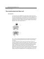
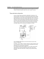
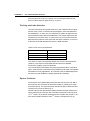
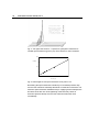
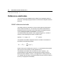
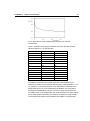
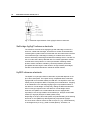
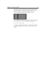
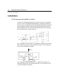
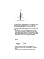
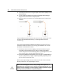
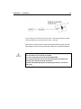
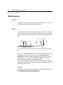
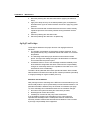
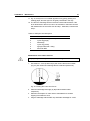
Antec Industrieweg 12 2382 NV Zoeterwoude The Netherlands VT-03 Electrochemical Flow cell User manual 110.0010, Edition 9, 2012 T +31 71 5813333 | F +31 71 5813334 | [email protected] | www.myantec.com Copyright ©2012, Antec, The Netherlands. Contents of this publication may not be reproduced in any form or by any means (including electronic storage and retrieval or translation into a foreign language) without prior agreement and written consent from the copyright of the owner. The information contained in this document is subject to change without notice. ROXY, ALEXYS, DECADE, DECADE II, INTRO, Flexcell, ISAAC, HyREF are trademarks of Antec. Whatman™ (word and device) and Whatrnan™ (word only) are trademarks of Whatman lnternational Ltd. SOLVENT IFD™ and AQUEOUS IFD™ are trademarks of Arbor Technologies, Inc. Clarity®, DataApex® are trademarks of DataApex Ltd. Microsoft® and Windows™ are trademarks of Microsoft Corporation. Excel is a registered trademark of the Microsoft Corporation. The software and the information provided herein is believed to be reliable. Antec shall not be liable for errors contained herein or for incidental or consequential damages in connection with the furnishing, performance, or use of software or this manual. All use of the software shall be entirely at the user’s own risk. INTRODUCTION Table of contents Table of contents I N T R O D U C T I O N Table of contents 3 The electrochemical flow cell 4 Introduction 4 Three-electrode configuration 5 Working electrode 6 Detection limit 7 Working electrode diameter 9 Spacer thickness 9 Reference electrodes 12 ISAAC reference electrode 12 Salt bridge Ag/AgCl reference electrode 14 HyREF reference electrode 14 Installation 16 VT-03 flow cell with HyREF or ISAAC 16 VT-03 flow cell with salt bridge REF 18 VT-03 micro flow cell 21 Assembling the micro flow cell 21 Capillary connections 24 Maintenance 28 HyREF 28 ISAAC 28 Polishing 28 Ag/AgCl salt bridge 29 Saturation and air bubbles 29 Material 30 Procedure 30 Maintenance of the cotton wool frit 31 Working electrode 32 Decreased flow cell performance 32 Polishing 33 Index 34 3 4 VT03 flow cell user manual, ed. 8 C H A P T E R 1 The electrochemical flow cell Introduction The VT-03 flow cell is available with a glassy carbon, platinum, gold, silver and copper working electrode. In combination with the spacer set (25, 50 and 120 µm) a variety of detection volumes (down to 5 nl) can be attained. As a standard, the salt bridge Ag/AgCl reference electrode is advised. For special applications the HyREF™ reference electrode is available. A third reference electrode is the in situ Ag/AgCl (ISAAC™). Fig. 1. The VT-03 electrochemical flow cell. The upper part, the inlet block, is separated from the working electrode block by means of a gasket (spacer, not shown). The VT-03 electrochemical flow cell has been developed for ultra-trace analysis in standard, microbore and capillary LC-EC. After extensive testing it was established that the confined wall-jet configuration gave the very best results. In addition it was found that the electrode materials quality and the finishing of the electrodes in the flow cell are decisive factors for the performance of an EC detector. While competitive designs usually deteriorate when in use, this flow cell, by design, improves in performance. The flow cell permits unusually short stabilisation times: trace analysis within half an hour CHAPTER 1 The electrochemical flow cell 5 after starting up may be expected. We have so much confidence in our flow cell that we warrant the glassy carbon flow cell for a period of 5 years. Three-electrode configuration In the VT-03 flow cell a three-electrode configuration is used (Fig. 2). The working potential is set between the working electrode (WE) and the auxiliary electrode (AUX). The AUX is kept at a precisely defined reference electrode (REF) potential by means of the so-called voltage clamp. This is an electronic feed back circuit that compensates for polarisation effects at the electrodes. At the WE, which is kept at virtual ground, the electrochemical reaction takes place, i.e. electrons are transferred at the WE. This results in an electrical current to the I/E converter, which is a special type of operational amplifier. The output voltage can be measured by an integrator or recorder. Fig. 2. Schematic representation of an electrochemical cell with a threeelectrode configuration. Essentially, for the oxidation or reduction reaction it would be sufficient to use only two electrodes. However, the three-electrode configuration has several advantages over a two-electrode configuration. If the working potential would be applied only over an AUX versus the WE (without REF), the working potential would continuously change due to polarisation effects at the electrodes, resulting in highly unstable working conditions. 6 VT03 flow cell user manual, ed. 8 If the working potential would be applied only over the REF versus the WE (without AUX), the working potential would be very well defined. However, the potential of a REF is only well defined if the current drawn is extremely low (pico-amperes) resulting in a very limited dynamic range. A three-electrode configuration, combines the best of both electrodes. The REF stabilises the working potential and the AUX can supply high currents. This results in the tremendous dynamic range of a three-electrode system. Working electrode Electrochemical detection puts high demands on the WE material. The WE should be made of a (electro-)chemically inert material. Furthermore, to avoid an irregular flow profile over the electrode, it should have a very well defined surface. Finally, it is important that the analyte of interest can be oxidised (or reduced) with favourable I/E characteristics. This in fact means that a high signal must be obtained at a low working potential. For most applications glassy carbon will be the WE material of choice. Under certain circumstances other materials are favourable. For example, for the analysis of iodide a silver WE can be used. At the silver WE the following oxidation reaction occurs for iodide: Ag + I AgI + e - - This reaction already takes place at a very low working potential (1 mV !), which results in an extremely high selectivity. This allows the determination of iodide in urine samples to take place almost without any sample pretreatment. CHAPTER 1 The electrochemical flow cell 7 Table I. Working potential limits and application area for different WE materials. WE material Glassy carbon Gold Platinum Silver Copper potential limits (V) alkaline acidic -1.50 -1.25 -0.90 -1.20 - -0.80 -0.35 -0.20 -0.55 - +0.60 +0.75 +0.65 +0.10 +0.60 major application +1.30 +1.10 +1.30 +0.40 - catecholamines carbohydrates alcohols, glycols halides, cyanide amino acids, carbohydrates Another consideration in choosing a WE is the oxidation or reduction of mobile phase constituents or WE material, that occurs when the potential exceeds the limits as given in Table I. At high positive working potentials the water in the mobile phase electrolyses and results in an strong increase of the background current and noise. Formation of metal oxides, resulting in an increase in background current is a limiting factor for metal electrodes. Glassy carbon and platinum have the highest positive potential limits and are therefore often used in oxidative ECD. For negative potentials the use of platinum electrodes is limited by the ease of reducing hydrogen ions to hydrogen gas. Detection limit One of the most important parameters used to characterise the performance of a detection system is the signal-to-noise ratio (S/N ratio) from which the concentration detection limit is derived. It enables objective comparison not only between different electrochemical detectors but also between complete analytical methods irrespective what detection system is used. Table II. LC-EC conditions for analysis of norepinephrine. column flow rate mobile phase sample temperature flow cell E cell Icell ODS-2, 3 µm, 100 x 4.6 mm 1.0 ml/min H3PO4 50 mM, citric acid 50 mM, 20 mg/l EDTA, 100 mg/l octane sulphonic acid (OSA), pH=3.1 with KOH, 5% methanol 1.0 µmol/l norepinephrine, 20 µl injection o 30 C VT-03 flow cell with 3 mm GC WE mounted with 50 µm spacer 800 mV (vs. Ag/AgCl, filled with saturated KCl) ca. 3 nA 8 VT03 flow cell user manual, ed. 8 In literature several ways are described to determined the detection limit. In principle, it does not matter which definition of detection limit is used, as long as the definition is precisely described. In this manual the concentration detection limit (cLOD) for a certain compound is defined as the analyte concentration that results in a signal that is 3 times the standard deviation of the noise: c LOD = 3 noise signal cA where sigma-noise is 0.2 x peak-to-peak noise and cA is the concentration of analyte injected. In Fig. 3 a typical S/N ratio of a VT-03 glassy carbon flow cell with 2.74 mm WE is shown. In this example the concentration detection limit for norepinephrine based on three times the sigma-noise is 11 pmol/l (see Table II for conditions). Expressing the performance of a detection system by only the peak height makes no sense. A system can easily be changed in a way that a larger peak height is obtained. However, if the noise increases similarly, it has the same effect as switching a recorder to a higher sensitivity: peaks appear higher but the S/N ratio is the same. Expressing the limit of detection in an absolute amount (i.e. in picomoles) without mentioning the injection volume, makes a good comparison between different systems difficult. Fig. 3. Typical S/N ratio for norepinephrine measured with a VT-03 glassy carbon flow cell (peak height: 80 nA, peak-to-peak noise: 1.5 pA). The CHAPTER 1 The electrochemical flow cell 9 amount injected is 20 pmol (1.0 µmol/l). The concentration detection limit based on three times the sigma-noise is 11 pmol/l. Working electrode diameter The size of the WE is an important factor in LC-EC, it affects both the signal and the noise. For the VT-03 flow cell several glassy carbon WE diameters are available (0.7, 2 and 3 mm). In a standard LC system the signal and the noise increases linearly with the WE diameter. This means that he S/N ratio remains more or less the same. In case of micro-LC an increase of the WE diameter will increase the noise more than the signal. Therefore, in micro-LC a decrease of the WE diameter will result in a better S/N ratio. Table III. Flow cell recommendations. Column diameter (mm) Recommended flow cell 3 and higher 3-1 1 and below 3 mm GC 2 mm GC 0.7 mm µGC The choice for a flow cell is primarily based on the HPLC column diameter (Table III). This way the best possible detection limit for a standard, microbore or capillary column is warranted. The recommended combinations are giving the best S/N ratios. It should be kept in mind that other combinations are possible that still result in acceptable sensitivities for many applications. All VT-03 flow cells are individually tested and meet our high standards of quality and detection sensitivity. Spacer thickness The thickness of the gasket affects the linear flow velocity in the cell. With a thinner spacer the cell volume is decreased (Table IV), resulting in a higher linear flow velocity. The signal increases with thinner spacers while the noise remains more or less constant (Fig. 4). Several authors have described the relation between the layer thickness (i.e. spacer thickness) in a thin layer flow cell and the measured current (S) as S -2/3 = k b where b is the spacer thickness and k a constant. Also for the VT-03 -2/3 flow cell the relation between S and b results in a straight line (Fig. 5). 10 VT03 flow cell user manual, ed. 8 Fig. 4. The signal and noise for 1.0 µmol/l nor-epinephrine measured at variable spacer thickness (given in µm). See Table II for other conditions. 200 S (nA) 100 0 0.02 0.04 0.06 0.08 0.10 0.12 b^(-2/3) Fig. 5. Peak height versus spacer thickness to the power -2/3. Decreasing the spacer thickness is limited by an increased pressure drop over the flow cell which eventually will lead to an obstruction of the flow. The minimum spacer thickness available is 25 µm. Applying these small spacers should be done with care. Over-tightening of the bolts may cause an excessive pressure built up over the flow cell and increase the noise considerably. CHAPTER 1 The electrochemical flow cell 11 Table IV. Flow cell volume spacer (µm) 25 50 120 WE diameter (mm) 3.00 2.74 2.54 2.00 1.90 1.00 0.75 0.50 cell volume (µl) 0.18 0.15 0.35 0.29 0.85 0.71 0.13 0.25 0.61 0.08 0.16 0.38 0.07 0.14 0.34 0.020 0.039 0.094 0.011 0.022 0.053 0.005 0.010 0.024 12 VT03 flow cell user manual, ed. 8 C H A P T E R 2 Reference electrodes The VT-03 flow cell is available with an ISAAC (in situ Ag/AgCl) reference electrode, a salt bridge Ag/AgCl reference electrode and a HyREF reference electrode. ISAAC reference electrode The ISAAC reference electrode is in direct contact with the mobile phase which contains chloride ions. The chloride concentration determines the potential, therefore each time a fresh mobile phase is prepared it should contain exactly the same concentration of chloride ions. The standard electrode potential of the Ag/AgCl electrode (in 1.0 mol/l Cl 0 solution) for the following half-reaction is defined as E : - - AgCl(s) + e <=> Ag(s) + Cl 0 E = 0.222 V The potential of the REF is dependent from the chloride concentration as described by the following equation: Ecell = E0AgCl - RT ln [Cl- ] F -1 -1 where R is the gas constant (8.314 Jmol K ), T is the absolute temperature -1 (293 K) and F is the Faraday constant (96485 Cmol ). The potential of the ISAAC at 2 mmol/l KCl is 379 mV (Table V). The potential difference (dE) between the saturated KCl Ag/AgCl reference electrode and the ISAAC is 189 mV. If an application is running at 800 mV (vs. Ag/AgCl with sat’d KCl), the potential setting using the ISAAC should be 611 mV (vs. Ag/AgCl in 2mmol/l KCl). CHAPTER 2 Reference electrodes 13 Fig. 6. Dependence of the Ag/AgCl REF potential on the chloride concentration. Table V. Potential of the Ag/AgCl reference electrode, dE is the potential difference with EAg/AgCl in saturated KCl. - Cl (mmol/l) 3500 2500 1500 500 100 20 10 8.0 6.0 4.0 2.0 1.0 0.5 E Ag/AgCl (mV) 190 199 212 240 280 321 338 344 351 361 379 396 414 dE (mV) 0 8 21 49 90 130 148 154 161 171 189 206 224 The addition of chloride to the mobile phase has a few restrictions. For example, the ISAAC is not recommended at a high working potential (> 1.2 V vs. Ag/AgCl in 2 mmol/l KCl) because Cl is oxidised and contributes to the background current. In ion chromatography the addition of Cl may lead to undesired chromatographic changes. In case of a silver working electrode, the addition of Cl to the mobile phase will cause formation of an AgCl coating on the working electrode leading to inactivation. At high pH or high modifier concentrations the ISAAC is less suitable and a HyREF is recommended. 14 VT03 flow cell user manual, ed. 8 Fig. 7. Schematic representation of the Ag/AgCl reference electrode. Salt bridge Ag/AgCl reference electrode The reference electrode of the Ag/AgCl type with salt bridge consists of a silver rod, coated with solid AgCl, immersed in a solution of saturated KCl, containing KCl crystals. Electrical contact with the other electrodes in the flow cell is made through a salt bridge consisting of a wetted cotton wool frit, which is electrically conducting and slows down leakage of KCl. This REF for the VT-03 flow cell is factory filled with KCl. For certain applications another chloride salt is to be preferred. In case of perchlorate containing mobile phases, sodium chloride is mandatory, because potassium perchlorate precipitates and will clog the cotton wool frit. At high modifier percentages, the REF must be filled with lithium chloride for similar reasons. HyREF reference electrode The HyREF is a hydrogen reference electrode, its potential depends on the pH of the mobile phase. The HyREF is fully comparable with the standard Ag/AgCl REF as to baseline stability and S/N ratio. The HyREF is more userfriendly and in principle this REF is completely free of maintenance. Trapping of air bubbles like in the salt bridge Ag/AgCl type is impossible because of the absence of a salt bridge. Consequently, refilling the REF with saturated KCl is not longer required. Due to the absence of a salt bridge and its inertness, the HyREF is an excellent alternative for the Ag/AgCl REF, especially in case of high modifier concentrations (i.e. analysis of fat-soluble vitamins) or high pH (analysis of carbohydrates, PAD). Depending on the pH of the mobile phase, the potential setting of the working electrode vs. the HyREF may differ significantly compared to Ag/AgCl. I/E curves show a shift of more than 200 mV at pH 3.1 (e.g. catecholamines), no shift appears at pH 12 (e.g. PAD of carbohydrates). Therefore, it is CHAPTER 2 Reference electrodes 15 advisable first to construct a hydrodynamic (or scanning) voltammogram when using the HyREF. In Table VI the potential of the HyREF is measured against the Ag/AgCl (in sat'd KCl) electrode at different pH values. Table VI. Measured cell potential (HyREF - Ag/AgCl) versus pH. PH EHyREF - Ag/AgCl (mV) 3.3 6.2 7.5 11.8 232 130 90 0 So, if an Ag/AgCl REF is replaced by a HyREF, the pH effect must be taken into account (Table VI). The pH vs. voltage relation is described by: EHyREF = EAg/AgCl - 328 + 29.9 pH (1) For example: a working potential of 800 mV (vs. Ag/AgCl with sat’d KCl) at pH 3, has to be changed to: EHyREF = 800 - 328 + 29.9*3 = 561.7 mV (vs. HyREF) 16 VT03 flow cell user manual, ed. 8 C H A P T E R 3 Installation VT-03 flow cell with HyREF or ISAAC The flow cell is assembled properly when it arrives. The force on the bolts is pre-set to 13 Ncm (“a little bit beyond fingertight”). Familiarise yourself with this force, since over-tightening of the bolts strongly deteriorates the S/N ratio and eventually the cell itself. Also, be aware that the black marks on both blocks should be in line. This ensures the best performance. For instructions about assembling the cell refer to page 20. Fig. 8. Installation of flow cell (Intro™ or DECADE™). WORK, AUX and REF are connected using the red, blue and black cell cable. LC out should be on top to prevent entrapment of bubbles. Fig. 9. Installation of flow cell (DECADE II™). WORK, AUX and REF are connected using the red, blue and black cell cable. LC out should be on top to prevent entrapment of bubbles. CHAPTER 3 Installation 17 The ISAAC reference electrode requires 2 mmole/l chloride ions (KCl or NaCL) in the mobile phase. Add and equilibrate before installation of the ISAAC. See manual electrochemical detector for optimisation of working potential 1. Connect the column outlet to the flow cell inlet, using small-bore PEEK tubing (0.3 mm ID) and one of the fingertights supplied. Use only our factory supplied fingertights in the flow cell, others may cause serious damage! Let the tubing protrude for ca. 1.5 cm from the fingertight fitting and tighten it such that the tubing is not or slightly indented by the fitting. 2. Do not over-tighten the fingertight. Over-tightening affects the flow pattern through the tubing (turbulence) and may strongly decrease the flow cell performance. 3. Connect 0.5 mm ID PEEK tubing to the outlet of the flow cell. Use only our factory supplied fingertights in the flow cell, others may cause serious damage! Again (see above), do not over-tighten the fingertight. 4. Turn on the HPLC pump. Keep some tissues at hand as you probably will spill some mobile phase during this mounting procedure. 5. Fill the flow cell, by keeping it in an angle of about 45° with the outlet (LC out) on top to force the air through the outlet. 6. Position the flow cell in its clamp in the controller with the REF at the lower side and the outlet at the upper side. This excludes trapping of air bubbles. 7. Connect the cell cable as illustrated in Fig. 8. Never switch ON the flow cell when: - the cell cable is not correctly connected - the cell is only partly (or not at all) filled with buffer/electrolyte - the outside of the flow cell is wet, particularly the part between the auxiliary and working electrode connection because substantial damage to the working electrode or electronics may occur. The maximum detection stability is attained when not only the flow cell, but also the HPLC column is incorporated in the controller. The controller has an integrated Faraday cage and an accurately thermostatted oven compartment 18 VT03 flow cell user manual, ed. 8 which ensures stable working conditions. Installing the flow cell and column within such a controlled environment is the minimum requirement for highquality LC-EC trace analyses. VT-03 flow cell with salt bridge REF The flow cell is assembled properly when it arrives. The force on the bolts is pre-set to 13 Ncm (“a little bit beyond fingertight”). Familiarise yourself with this force, since over-tightening of the bolts strongly deteriorates the S/N ratio and eventually the cell itself. Also, be aware that the black marks on both blocks should be in line. This ensures the best performance. For instructions about assembling the cell refer to page 20. Fig. 10. Installation of flow cell (in Intro or DECADE). WORK, AUX and REF are connected using the red, blue and black cell cable. The LC outlet is placed on top to prevent entrapment of bubbles. Fig. 11. Installation of flow cell (DECADE II). WORK, AUX and REF are connected using the red, blue and black cell cable. The LC outlet is placed on top to prevent entrapment of bubbles. CHAPTER 3 Installation 19 Use proper eye and skin protection when working with solvents. 1. Check the REF visually for air bubbles and saturation with KCl. Some KCl crystals should be visible. When no crystals are visible or air bubbles are trapped the REF needs maintenance (see page 29). To prevent drying-out the REF is sealed with a cap on arrival. Remove the cap. 2. Tighten the black swivel of the REF, a small droplet should appear at the cotton-wool frit. Do not remove this droplet because it ensures proper contact of the REF with the mobile phase. 3. Turn on the HPLC pump. Place some tissues as some mobile phase may be spilled during this mounting procedure. Connect the column outlet to the flow cell inlet, using small-bore PEEK tubing (0.3 mm ID) and one of the fingertights supplied. Use only our factory supplied fingertights in the flow cell, others may cause serious damage! Let the tubing protrude for ca. 1.5 cm from the fingertight and tighten it carefully. 4. 5. 6. 7. 8. Over-tightening affects the flow through the tubing (turbulence) and decreases the flow cell performance. Connect 0.5 mm ID PEEK tubing to the outlet of the flow cell. Use only our factory supplied fingertights in the flow cell, others may cause serious damage! Again (see above), do not over-tighten the fingertight. Fill the flow cell, by keeping it in an angle of 45° with the REF fitting on top, is best done by blocking the outlet with a finger and letting the air escape via the REF fitting. Carefully check the thread of the fitting for trapped air bubbles. When the REF fitting is completely filled with mobile phase, mount the REF while slowly releasing the outlet. Make sure not to include an air bubble! Position the flow cell in its clamp in the controller with the REF at the lower side and the outlet at the upper side. This excludes trapping of air bubbles by the REF. Connect the cell cable as illustrated in Fig. 10. The maximum detection stability is attained when not only the flow cell, but also the HPLC column is incorporated in the controller. The controller has an integrated Faraday cage and an accurately thermostatted oven compartment which ensures stable working conditions. Installing the flow cell and column 20 VT03 flow cell user manual, ed. 8 within such a controlled environment is the minimum requirement for highquality LC-EC trace analyses. Never switch ON the flow cell when: - the cell cable is not correctly connected - the cell is only partly (or not at all) filled with buffer - the outside of the flow cell is wet, particularly the part between the auxiliary and working electrode connection because substantial damage to the working electrode or electronics may occur. When not in use, please store the REF with the cotton wool frit immersed in a saturated KCl solution to prevent drying out. Fig. 12. Always install flow cell with outlet on top. CHAPTER 3 Installation 21 VT-03 micro flow cell The micro flow cell is assembled properly when it arrives. The force on the bolts is pre-set to 13 Ncm (“a little bit beyond fingertight”). Familiarise yourself with this force, since over-tightening of the bolts strongly deteriorates the S/N ratio and eventually the cell itself. Also, be aware that the black marks on both blocks should be in line. This ensures the best performance. Assembling the micro flow cell The VT-03 micro flow cell has an 0.7 mm WE and is equipped with a 25 µm spacer. Older models of the VT-03 micro are equipped with a metal centring ring. In that case both blocks (WE and inlet block) have an edge/groove to facilitate the metal ring and are fixed in the metal ring to align the inlet in the centre of the WE. Fig. 13. Disassembled VT-03 micro flow cell with spacer. Note: new VT03 micro cells purchased after 2009 are delivered without metal centring ring and have no groove in WE and inlet block. To assure proper installation and optimal performance please follow the instruction below for assembling of a VT-03 micro flow cell. It is also strongly advised to assemble normal VT-03 flow cells (2 mm and 3 mm GC) using a similar procedure. Mounting the cell in another manner may lead to damage of the spacer and flow cell blocks. For cells without metal centring ring discard/skip the sections in the procedure related to placement of the centring ring. 22 VT03 flow cell user manual, ed. 8 1. Hold the WE block in horizontal position with the WE facing downwards and insert the 4 bolds in the 4 mounting holes of the WE block. Place the glass mounting plate on top of it, turn the glass plate with WE block up side down and place it on a flat surface/table. Fig. 14. WE block with inserted bolds on the glass mounting plate. 2. Place the metal ring on the WE block. Make sure that you hold the metal ring horizontally when pushing it onto the block. Subsequently, gently place the 25 µm spacer on top of the WE block with bolds using a pair of tweezers . The spacer should lay flat on the WE surface with the bolds centred in the spacer bold holes. Fig. 15. Placement of 25 µm spacer on the WE block. 3. Place the inlet block on top of the WE block as depicted in the next figure. When placing the block keep it tilted and gently try to position the two bold holes in the inlet block on top of the bolds without CHAPTER 3 Installation 23 touching the surface of the inlet block with the bold ends (this will minimize the change of scratching the inlet block surface). Then turn the inlet block downwards in horizontal position. The inlet block will now lay on top of the WE block with the bolds positioned on the mounting holes. The black positioning markers on the sides of the blocks should now be aligned in vertical position. Fig. 16. Positioning the inlet block on top of the WE block. Fig. 17. Inlet block positioned on top of WE electrode, note that black positioning markers are aligned in vertical position. 4. Hold the complete cell together with the glass mounting plate and turn it up side down again. Take of the glass plate and position it underneath the cell again. Tighten the bolds in a crosswise pattern with the hex key (tightening force ~ 13 Ncm). Now the cell is ready for use again. 24 VT03 flow cell user manual, ed. 8 Fig. 18. Fixing the two cell blocks with the hex key (tighten the bolds in a crosswise pattern). Capillary connections The micro flow cell is supplied with a low dead-volume fused silica capillary connection for coupling with capillary columns (< 1 mm ID fused silica columns) as a standard. Use proper eye and skin protection when working with solvents. If the capillary connection has already been installed properly, continue with step 11. If not, start with step 1. When disconnecting the column, always slowly release pressure, or damage to the column will occur. Tighten low dead coupling (Fig. 21, 1) firmly to avoid snapping out of the capillary. Sudden pressure drop will destroy column performance and pulse dampener! CHAPTER 3 Installation 25 Fig. 19. Mounting of the fused silica connector in the VT-03 micro flow cell. The capillary connector is not necessary with a 1 mm (or larger ID) column. In that case use narrow bore PEEK tubing ( 100 µm ID), and install as described on page 16 (ISAAC REF) or on page 18 (salt bridge REF). To prevent any damage to the flow cell the following steps should be carried out (Fig. 19): 1. Connect the FS capillary to the pump (by-passing the column) and switch on the pump to check that the capillary is open. Liquid droplets must come out. Otherwise replace with new piece of 100 um FS tubing. Note that both endings of the supplied FS capillary are cut and polished! 2. If the capillary is open, first switch off the pump and wait till the pressure is zero. Disconnect the capillary from the pump. 3. Insert the fused silica capillary into the tightly fitting Teflon sleeve supplied. 4. Protrude both through our factory supplied fingertight fitting. Use only our factory supplied fingertights in the flow cell, others may cause serious damage! 5. Mount this combination carefully in the injection block (Fig. 19). 6. Let the fused silica slightly (< 0.5 mm) protrude through the injection hole. 7. Clean the factory supplied glass mounting plate from particles. 26 VT03 flow cell user manual, ed. 8 8. Carefully push the block on the glass plate until the silica capillary is flush with the surface. 9. Fix the fused silica capillary firmly with the fingertight while keeping a slight pressure of the block on the glass plate. 10. Mount the two flow cell blocks by crosswise tightening of the bolts (max. 13 Ncm). Fig. 20. Different column connectors with micro flow cell. Column type A has no ferrule, but ends with fused silica (1). Column type B has a ferrule connector (1). On the left (A) the standard installation with capillary connector (2). This is suitable for fused silica columns. On the right (B), installation with a ferrule and sleeve connected to the column. 11. Connect the other end of the capillary connector as shown in Fig. 20. Use either a ferrule with sleeve (Fig. 20B) or couple to the capillary column using the connector sleeve (Fig. 20A, 2). If leakage occurs, a low dead coupler can be used with fingertights and sleeve. 12. Continue installation as described at point 3 on page 17 (ISAAC REF) or at point 1 (skip point 3) on page 19 (salt bridge REF), depending on the type of reference electrode used. NB: To speed up the filling of the micro flow cell, the cell can be connected directly to the HPLC, thus by-passing the column. When disconnecting the column, always slowly release pressure, or damage to the column will occur. Tighten low dead coupling (Fig. 21, 1) firmly to avoid snapping out of the capillary. Sudden pressure drop will destroy column performance and pulse dampener! CHAPTER 3 Installation 27 Fig. 21. Filling a VT-03 micro flow cell at 200 – 400 µL/min using a low deadvolume connector (1). Pressure must not rise > 200 bar. Read column instructions first. The flow cell is then filled at a higher flow rate. After filling the column is reconnected. Be careful not to include air bubbles! Never switch ON the flow cell when: - the cell cable is not correctly connected - the cell is only partly (or not at all) filled with buffer - the outside of the flow cell is wet, particularly the part between the auxiliary and working electrode connection because substantial damage to the working electrode or electronics may occur. 28 VT03 flow cell user manual, ed. 8 C H A P T E R 4 Maintenance HyREF The HyREF reference electrode is in principle maintenance free. If not in use it should be stored dry after disassembling the flow cell. ISAAC The ISAAC reference electrode requires maintenance, usually not more than once in 3 months. In practice this means that when the flow cell is opened to service the working electrode, the reference electrode should be serviced as well. A B reference electrode solution reference electrode surface Fig. 22. Servicing the ISAAC reference electrode, polishing (A) and coating (B). Servicing the reference electrode is done by polishing the reference electrode surface until the shining metal appears (Fig. 22A). Immediately after polishing the electrode is coated by applying a few drops of the reference electrode solution on the reference surface (Fig. 22B). After 20 min the reference solution is flushed away with distilled water. If not in use for longer period of time, disassemble the flow cell. The flow cell including the reference electrode should be cleaned with distilled water, dried with a tissue and stored dry. Polishing Polishing the reference electrode is done using the factory supplied polishing kit, containing diamond slurry and polishing disc. 1. Shake diamond slurry thoroughly before use!! CHAPTER 4 Maintenance 29 2. Rinse the polishing disc with demi water before applying the diamond slurry! 3. Apply a few drops of slurry on the wetted polishing disc, and polish the electrode with a ‘figure 8’ motion for about one minute. Apply only gentle pressure. 4. Clean the electrode with a wetted tissue and check the surface visually, repeat the procedure if necessary until the shining metal REF surface appears. 5. Clean the polishing disc with demi water. 6. Store the polishing disc dust free in its plastic bag. Ag/AgCl salt bridge Three aspects determine the proper function of an Ag/AgCl reference electrode. 1. The chloride concentration must be kept at a strictly fixed level. This is best guaranteed by using a saturated chloride salt solution at a constant temperature. 2. The salt bridge must allow proper electrical contact with the mobile phase. The higher the leakage through the frit the better the conduction. This conflicts with the previous point. 3. Air bubbles inside or close to the salt bridge will lead to instability of the three-electrode configuration. Because of their extreme compressibility, changes in conductivity and the ionic equilibrium of the REF occur. This increases the noise considerably. The REF is factory filled with KCl unless specified otherwise. Other chloride salts should be used when the mobile phase contains perchlorate (use NaCl) or a high percentage of organic modifier (use LiCl). Saturation and air bubbles After prolonged use the salt bridge in the REF will not be saturated any more, which usually leads to a poor reproducibility in electrochemical detection. The potential of the REF is determined by the chloride concentration (see page 13). If the salt bridge is not saturated and the KCl concentration changes: 1. the noise in the system will slowly but continuously increase, 2. the background current will increase, 3. sensitivity for movements and pump noise will increase. If an air bubble is trapped in the salt bridge or in the cotton plug that separates the salt bridge and the mobile phase the flow cell becomes extremely sensitive towards flow fluctuations and vibrations. This is caused by the high compressibility of the trapped air. 30 VT03 flow cell user manual, ed. 8 Check your REF regularly. If you do not see chloride salt crystals or if you see air bubbles, your REF needs maintenance. Material 1. An over-saturated and thoroughly degassed KCl solution. 2. A stainless steel rod of about 5 cm length and a diameter of 1 mm (e.g. a 1 mm drill). 3. Ordinary cotton wool. Procedure Use proper eye and skin protection when working with solvents. 1. 2. 3. 4. 5. 6. 7. Turn the cell OFF on the controller. Stop the HPLC pump. Disconnect the cell from the controller. Remove the REF from the inlet block. Disassemble the REF by unscrewing the black swivel ( Fig. 23). Inspect the Vyton rings for wearing and especially the cotton wool frit, replace if required (see below). Fig. 23. Exploded view of the reference electrode. The arrow indicates the tip of the AgCl coated silver rod. See Table VII for description and numbers. 8. Remove the remaining KCl from the salt bridge. 9. Clean all parts with demi-water. 10. The Ag/AgCl electrode must be cleaned if the silver on the tip ( CHAPTER 4 Maintenance 31 11. Fig. 23, arrow) has a non-metallic appearance by gently grinding it on sanding paper; also the AgCl can be gently resurfaced in this way. 12. The frit in the salt bridge ensures electrical contact with the buffer. If the frit is discoloured or dried out, it has to be renewed. In that case continue with ‘Maintenance of the cotton wool frit’ step 1. Otherwise, continue with step 7. Table VII. REF parts and description. Item Description 1 2 3 4 5 6 REF cap for storage and shipment Vyton ring (large) Salt bridge Vyton ring (small) Ag/AgCl electrode + fitting Swivel for REF Maintenance of the cotton wool frit Use proper eye and skin protection when working with solvents. 1. Use a drill of ± 1 mm (0.039 inch) to push out the frit from the outside (Fig. 24). Be careful not to damage the frit constriction (first arrow). Fig. 24. Pushing the cotton wool frit out. 2. Clean the salt bridge thoroughly by tap water and demi-water respectively. 3. Saturate a small piece of cotton-wool in saturated KCl to exclude trapping of air within the wool. 4. Plug the salt bridge with the REF cap and fill the salt bridge for ± 50%. 32 VT03 flow cell user manual, ed. 8 5. Use the drill to pack the wool from above through the KCl solution into the channel of the salt bridge, compress it firmly, but not too much, since electrical conduction is essential. 6. Remove the cap. 7. Fill the salt bridge completely, add some KCl crystals out of a saturated solution to ensure prolonged saturation. 8. Place the small Vyton ring over the Ag/AgCl electrode and slowly insert o it, in an angle of 45 into the salt bridge. Make sure not to enclose an air bubble. 9. Tighten the black swivel such that a small droplet appears at the end of the salt bridge, but do not over-tighten the swivel. 10. Flush the complete, mounted REF with demi-water, dry it with a tissue, but keep the cotton wool frit soaked. 11. Carefully inspect the REF visually for trapped air bubbles, otherwise remove them (go back to step 7 or if necessary step 1). When not in use, please store the REF with the cotton wool frit immersed in a saturated KCl solution to prevent drying out. Working electrode Cleaning of the working electrode block is necessary if the electrode surface has been electrochemically changed. This may be due to fouling by oxidation (reduction) reaction products. Excessively high currents also may change the electrode surface. This is noticed by a strongly decreased sensitivity after prolonged use. As a rule of thumb: only polish if the surface of the working electrode lacks its mirror-like finish, which cannot be restored by wiping the electrode surface with a tissue wetted with ethanol or acetone. Decreased flow cell performance Use proper eye and skin protection when working with solvents. Several actions can be taken at decreased flow cell performance. Avoid unnecessary polishing, take the next step only if the previous was not successful. 1. Electrochemical cleaning of glassy carbon WE: In the pulse mode let the potential jump between +1 and -1 V for 10 min. Settings: t1 = 1000 ms, t2 = 1000 ms, t3 = 0 ms, E1 = +1V, E2 = -1V. 2. Wiping the electrode surface with a tissue wetted with ethanol or acetone CHAPTER 4 Maintenance 3. Polishing the electrode surface Polishing 1. Shake diamond slurry thoroughly before use!! 2. Rinse the polishing disc with demi water before applying the diamond slurry! 3. Apply a small amount, a few drops is sufficient, of slurry on the wetted polishing disc, and polish the electrode with a ‘figure 8’ motion for about one minute. Apply only gentle pressure. 4. Clean the electrode with an ethanol-wetted tissue and check the surface visually; repeat the procedure if necessary. 5. Reassemble the detector cell. 6. Clean the polishing disc with demi water. 7. Store the polishing disc dust free in its plastic bag. 33 34 VT03 flow cell user manual, ed. 8 C H A P T E R Index 5 CHAPTER 5 Index Ag/AgCl reference electrode parts, 29 standard electrode potential, 12 auxiliary electrode, 5 detection limit, 7 flow cell volume, 11 HyREF installation, 16 reference electrode potential, 14 I/E converter, 5 installation micro flow cell, 21 installation flow cell, 16 ISAAC installation, 16 reference electrode potential, 12 maintenance cotton wool frit, 29 HyREF, 26 ISAAC, 26 salt bridge, 27 working electrode, 30 micro flow cell installation, 21 parts Ag/AgCl reference electrode, 29 polishing, 26, 31 reference electrode, 5, 12 salt bridge, 14 installation, 18 signal-to-noise ratio, 7 spacer thickness, 9 three-electrode configuration, 5 voltage clamp, 5 warranty, 5 working electrode, 5, 6 working electrode diameter, 9 working potential limits, 7 35