1
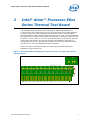
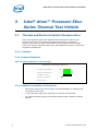
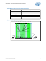
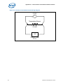
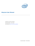
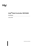
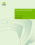
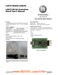
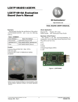
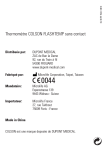
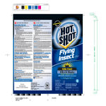
Intel® Atom™ Processor E6xx
Series Thermal Test Board
User Guide
September 2010
Document Number: 324473-001
INFORMATION IN THIS DOCUMENT IS PROVIDED IN CONNECTION WITH INTEL® PRODUCTS. NO LICENSE,
EXPRESS OR IMPLIED, BY ESTOPPEL OR OTHERWISE, TO ANY INTELLECTUAL PROPERTY RIGHTS IS GRANTED BY THIS
DOCUMENT. EXCEPT AS PROVIDED IN INTEL’S TERMS AND CONDITIONS OF SALE FOR SUCH PRODUCTS, INTEL ASSUMES NO
LIABILITY WHATSOEVER, AND INTEL DISCLAIMS ANY EXPRESS OR IMPLIED WARRANTY, RELATING TO SALE AND/OR USE OF
INTEL PRODUCTS INCLUDING LIABILITY OR WARRANTIES RELATING TO FITNESS FOR A PARTICULAR PURPOSE,
MERCHANTABILITY, OR INFRINGEMENT OF ANY PATENT, COPYRIGHT OR OTHER INTELLECTUAL PROPERTY RIGHT. NLESS
OTHERWISE AGREED IN WRITING BY INTEL, THE INTEL PRODUCTS ARE NOT DESIGNED NOR INTENDED FOR ANY APPLICATION
IN WHICH THE FAILURE OF THE INTEL PRODUCT COULD CREATE A SITUATION WHERE PERSONAL INJURY OR DEATH MAY
OCCUR.
Intel may make changes to specifications and product descriptions at any time, without notice. Designers must not rely on the
absence or characteristics of any features or instructions marked “reserved” or “undefined.” Intel reserves these for future
definition and shall have no responsibility whatsoever for conflicts or incompatibilities arising from future changes to them. The
information here is subject to change without notice. Do not finalize a design with this information.
The products described in this document may contain design defects or errors known as errata which may cause the product to
deviate from published specifications. Current characterized errata are available on request.
Contact your local Intel sales office or your distributor to obtain the latest specifications and before placing your product order.
Copies of documents which have an order number and are referenced in this document, or other Intel literature, may be
obtained by calling 1-800-548- 4725, or by visiting Intel’s Web Site.
Intel processor numbers are not a measure of performance. Processor numbers differentiate features within each processor
family, not across different processor families. See http://www.intel.com/products/processor_number for details.
Code Names are for use by Intel to identify products, platforms, programs, services, etc. (“products”) in development by Intel
that have not been made commercially available to the public, i.e., launched or shipped. They are never to be used as
“commercial” names for products or intended to function as trademarks.
α Hyper-Threading Technology requires a computer system with a processor supporting HT Technology and an HT Technologyenabled chipset, BIOS and operating system. Performance will vary depending on the specific hardware and software you use.
For more information including details on which processors support HT Technology, see
http://www.intel.com/products/ht/hyperthreading_more.htm.
β Intel® High Definition Audio requires a system with an appropriate Intel® chipset and a motherboard with an appropriate
CODEC and the necessary drivers installed. System sound quality will vary depending on actual implementation, controller,
CODEC, drivers and speakers. For more information about Intel® HD audio, refer to http://www.intel.com/.
χ 64-bit computing on Intel® architecture requires a computer system with a processor, chipset, BIOS, operating system, device
drivers and applications enabled for Intel® 64 architecture. Performance will vary depending on your hardware and software
configurations. Consult with your system vendor for more information.
δ Intel® Virtualization Technology requires a computer system with an enabled Intel® processor, BIOS, virtual machine monitor
(VMM) and, for some uses, certain computer system software enabled for it. Functionality, performance or other benefits will
vary depending on hardware and software configurations and may require a BIOS update. Software applications may not be
compatible with all operating systems. Please check with your application vendor.
ε The original equipment manufacturer must provide Trusted Platform Module (TPM) functionality, which requires a TPMsupported BIOS. TPM functionality must be initialized and may not be available in all countries.
I2C* is a two-wire communications bus/protocol developed by Philips. SMBus is a subset of the I2C* bus/protocol and was
developed by Intel. Implementations of the I2C* bus/protocol may require licenses from various entities, including Philips
Electronics N.V. and North American Philips Corporation.
BunnyPeople, Celeron, Celeron Inside, Centrino, Centrino Inside, Core Inside, FlashFile, i960, InstantIP, Intel, Intel logo,
Intel386, Intel486, IntelDX2, IntelDX4, IntelSX2, Intel Atom, Intel Atom Inside, Intel Core, Intel Inside, Intel Inside logo, Intel
NetBurst, Intel NetMerge, Intel NetStructure, Intel SingleDriver, Intel SpeedStep, Intel StrataFlash, Intel Viiv, Intel vPro, Intel
XScale, Itanium, Itanium Inside, MCS, MMX, Oplus, PDCharm, Pentium, Pentium Inside, skoool, Sound Mark, The Journey
Inside, Viiv Inside, vPro Inside, VTune, Xeon, and Xeon Inside are trademarks of Intel Corporation in the U.S. and other
countries.
*Other names and brands may be claimed as the property of others.
Copyright © 2010, Intel Corporation. All rights reserved.
2
Thermal Test Board User Guide
Contents
1
Introduction....................................................................................................... 6
2
Intel® Atom™ Processor E6xx Series Thermal Test Board ........................................ 7
3
Intel® Atom™ Processor E6xx Series Thermal Test Vehicle ...................................... 8
3.1
3.2
4
Thermal and Electrical Vehicle Characteristics ............................................. 8
3.1.1
Heaters ..................................................................................... 8
3.1.1.1
Heater Dimension ........................................................ 8
3.1.1.2
Heater Connectivity and Locations ................................. 8
3.1.2
Temperature Sensors................................................................ 10
Temperature Sensor Usage ..................................................................... 12
3.2.1
Temperature Sensor Calibration ................................................. 12
3.2.1.1
Four-Wire Resistance Calibration ................................. 12
3.2.2
Temperature Measurements ...................................................... 14
3.2.3
Thermal Solution and Still Air Chamber ....................................... 15
Summary ........................................................................................................ 16
Appendix A - Thermal Test Board Design .................................................................. 17
Appendix B – Thermal Test Board Dimensions ........................................................... 19
Appendix C – Thermal Test Board Photos .................................................................. 20
Appendix D - 4-wire Constant Current Measurement Procedure ................................... 21
D.1
Constant Current Measurement Theory .................................................... 21
Thermal Test Board User Guide
3
Figures
Figure 1. Side View of Thermal Test Vehicle Package .............................................. 6
Figure 2. Top and Bottom View of Thermal Test Vehicle Package .............................. 6
Figure 3. Thermal Test Board Designed for the Intel® Atom™ Processor E6xx Series
Thermal Vehicle .................................................................................... 7
Figure 4. Heater Dimension on the Test Chip ......................................................... 8
Figure 5. Heater Layout on the Test Chip ............................................................... 9
Figure 6. Electrical Connections to Power the Heater on the Test Chip While Monitoring
Voltage and Current ............................................................................ 10
Figure 7. Schematic of Temperature Sensor Locations........................................... 11
Figure 8. Example of Electrical Connections of ‘Die-Center’ Temperature Sensor for 4Point Measurement ............................................................................. 12
Figure 9. Example of Four-Wire Resistance Measurement Setup ............................. 13
Figure 10. Example of Thermal Die Sensor (TS_DC) Characteristics Using a Four-wire
Resistance Calibration ....................................................................... 14
Figure 11. Temperature Measurement Setup ....................................................... 15
Figure 12. Thermal Solution and Still Air Chamber for Temperature Measurement .... 15
Figure 13. Mechanical Dimensions and Enabling Holes Location .............................. 19
Figure 14. Edge Fingers and Through-hole Pin Headers ......................................... 20
Figure 15. Constant Current Measurement Wiring Diagram .................................... 22
Tables
Table 1. Heater Connectivity on the Thermal Test Vehicle ........................................ 9
Table 2. Electrical Connections of the Temperature Sensor for 4-Point Measurement 10
Table 3. Temperature Sensors and Heaters Connectivity ....................................... 17
4
Thermal Test Board User Guide
Revision History
Rev. No.
Description
Rev. Date
1.0
Initial Release
June 2010
2.0
First SKU launch
September 2010
Thermal Test Board User Guide
5
Introduction
1
Introduction
A thermal test board is provided by Intel to aid in embedded system thermal designs
for the latest Intel embedded processor product, Intel® Atom™ Processor E6xx Series.
Figure 1 and Figure 2 show a side, and top/bottom view of the Intel® Atom™
Processor E6xx Series thermal test vehicle (FCBGA package).
Figure 1. Side View of Thermal Test Vehicle Package
Die
BGA
Figure 2. Top and Bottom View of Thermal Test Vehicle Package
The thermal test board (TTB) is designed to be used with an FCBGA thermal test
vehicle to facilitate proper connections to the various heaters and temperature sensor
structures. Test vehicle structures are accessible through TTB as per information given
in Appendix A. Additionally, a Gerber file for the TTB can also be available from your
Intel representative. This Gerber file can be modified to resemble a notebook planar
board. Please contact your Intel representative for obtaining any TTB boards, or its
Gerber file.
To use an FCBGA thermal test vehicle, it must be surface mounted onto a test board.
The test vehicle structures can be accessed as per the pin/ball map, as shown in
Appendix A.
6
Thermal Test Board User Guide
Intel® Atom™ Processor E6xx Series Thermal Test Board
2
Intel® Atom™ Processor E6xx
Series Thermal Test Board
The enabling thermal test board (TTB), designed for FCBGA type packages, is
5.5 inches long, and 4 inches wide. Figure 3 shows the layout for the PCB (designed
by Intel) to power and read temperature from the Intel® Atom™ Processor E6xx
Series thermal test vehicle through edge connector, from 1 to 36. The connections are
also designed for through-hole pin headers temperature measurement from D1 to D9,
for both A+ and B-, where A+ is the set of top tabs and B- are connected to the tabs
on the lower side of board. The through via-pairs are separately routed and are
distinguished as x and y, x being the on the higher tab number or placed to the left
side of the y. P1 to P3 are designed for heater connection.
There are a total of 4 holes provided in the TTB for heat sink/thermal solution
attachment (refer to Figure 13).
Figure 3. Thermal Test Board Designed for the Intel® Atom™ Processor E6xx Series
Thermal Vehicle
Thermal Test Board User Guide
7
Intel® Atom™ Processor E6xx Series Thermal Test Vehicle
Intel® Atom™ Processor E6xx
Series Thermal Test Vehicle
3
3.1
Thermal and Electrical Vehicle Characteristics
This section describes the thermal attributes of the thermal test vehicle (TTV),
electrical connections of the heater and temperature sensors, temperature
measurements, and test vehicle specifications. The thermal test vehicle includes
heaters to simulate component power levels and temperature sensors to monitor the
component temperatures.
3.1.1
Heaters
3.1.1.1 Heater Dimension
Figure 4. Heater Dimension on the Test Chip
Heater Dimension: 9250 x 9250 um >90% die area
M9 width 33 um; Min spacing 13 um
M8
M9 length – approximately 911 um
2 v8 per M8 - 1.4 um x 10 um
M8 width 2.5 um; Pitch 8.41 um
Two V8
M8 length ~9250 um
3.1.1.2 Heater Connectivity and Locations
8
•
Each group of five FH and five FL bumps are shorted together on substrate and
connected to 3 BGA each.
•
5 uvias and PTH is required on each layer for each FH and FL pinouts.
•
For whole die heating connect HTR_FH/MH and HTR_FL/ML. Otherwise, half die
heating.
Thermal Test Board User Guide
Intel® Atom™ Processor E6xx Series Thermal Test Vehicle
Table 1. Heater Connectivity on the Thermal Test Vehicle
Net Name
Package Pin
HTR_FH
A1.G13 A1.H12 A1.J13
HTR_MH
A1.H15
HTR_FI_FH
A1.G25 A1.H24 A1.J25
HTR_FI_MH
A1.H26
HTR_FL
A1.G39 A1.H40 A1.J39
HTR_ML
A1.H37
Figure 5. Heater Layout on the Test Chip
911
911
911
911
911
911
911
1 Hanging M8 line to enable M9 spacing
HTR_ML
HTR_FI_MH
HTR_MH
HTR_FI_FH
HTR_FH
Thermal Test Board User Guide
455.5
911
911
911
911
911
911
455.5
HTR_FL
9
Intel® Atom™ Processor E6xx Series Thermal Test Vehicle
Figure 6. Electrical Connections to Power the Heater on the Test Chip While Monitoring
Voltage and Current
V
Digital Voltmeter
Heater Resistor
Digital
Current
Meter
I
DC Power
Supply
3.1.2
Temperature Sensors
Resistive Temperature Detector (RTD) type temperature sensors are used. Here the
temperature sensors measure the die temperature by using a linear relationship
between either the sensor resistance, or the voltage drop across the resistor, and the
sensor temperature. For example, as the temperature increases, the measured
voltage drop across the temperature sensor increased for a given constant current
condition. By calibrating this sensor voltage drop with respect to temperature, one can
determine the device temperature from voltage measurements.
Note: Both measurement methods (constant current, and 4-wire resistance measurement)
produce comparable accuracy. The choice of measurement method can be decided by
the user depending upon the available instrumentation.
There are a total of 6 temperature sensors on the test chip. TS_DC is recommended to
mimic hot-spots location on the actual processor silicon.
Table 2. Electrical Connections of the Temperature Sensor for 4-Point Measurement
Netnames
Test
Type
10
Test
Name
Package Pin
Force
Measure
Force
High
Measur
e High
Force
Low
Measure
Low
RES
TS_BL
TS_BL_FH
TS_BL_FL
A1.V7
A1.T7
A1.U6
A1.W6
RES
TS_BR
TS_BR_FH
TS_BR_FL
A1.L45
A1.R46
A1.N45
A1.M46
RES
TS_DC
TS_DC_F
H
TS_DC_F
L
A1.BE16
A1.BD17
A1.BD15
A1.BE18
RES
TS_RE
TS_RE_FH
TS_RE_FL
A1.AE45
A1.AH44
A1.AF44
A1.AG45
RES
TS_TL
TS_TL_FH
TS_TL_FL
A1.AY6
A1.BB6
A1.AW7
A1.BA7
RES
TS_TR
TS_TR_FH
TS_TR_FL
A1.AW45
A1.BB46
A1.AY46
A1.BA45
Thermal Test Board User Guide
Intel® Atom™ Processor E6xx Series Thermal Test Vehicle
An example of the electrical connection schematic for the temperature sensors is
illustrated in Figure 8. Here, for 4-wire measurement, a 1 mA constant current source
is applied to the temperature sensor while a multi-meter is used to measure the
voltage across the temperature sensor.
Figure 7. Schematic of Temperature Sensor Locations
TS_DC
TS_TR
TS_TL
TS_RE
TS_BL
TS_BR
TS_xx
Thermal Test Board User Guide
= Temp Sensor
11
Intel® Atom™ Processor E6xx Series Thermal Test Vehicle
Figure 8. Example of Electrical Connections of ‘Die-Center’ Temperature Sensor for 4Point Measurement
3.2
Temperature Sensor Usage
This section describes temperature sensor calibration and measurements.
3.2.1
Temperature Sensor Calibration
Before the thermal vehicle can be used for system thermal characterization, the
temperature sensors must be calibrated in the manner described in one of the
following sections. The sensors should be calibrated preferably in a constant
temperature chamber, otherwise the sensor will require a larger amount of time to
soak and reach steady state.
3.2.1.1 Four-Wire Resistance Calibration
A four-wire resistance calibration requires the use of a multi-meter or a data
acquisition unit that is designed to accept inputs for a four-wire measurement. Each of
the sensors should be instrumented in a manner similar to the one shown in Figure 9.
Warning:
12
Do not use a two-wire resistance measurement for calibration or thermal testing
because it may result in inaccurate temperature measurements. For more details
on the differences between a two-wire and four-wire measurement, refer to
Appendix D.
Thermal Test Board User Guide
Intel® Atom™ Processor E6xx Series Thermal Test Vehicle
Figure 9. Example of Four-Wire Resistance Measurement Setup
The calibration procedure is as follows:
1. Connect the temperature sensor to a multi-meter or a data acquisition unit that is
capable of taking four-wire resistance measurements. Refer to the example shown
in Figure 9.
2. Place the thermal vehicle in a constant temperature bath, using 0º C as the initial
temperature setting. Soak the unit for a sufficient amount of time in order to allow
the thermal vehicle to reach thermal equilibrium with the bath.
3. Measure the resistance of the temperature sensor and record the thermal bath
temperature.
4. Reset the temperature of the thermal bath to 30º C and continuously monitor the
bath temperature and temperature sensor resistance. Wait for a sufficient amount
of time until the bath and thermal vehicle reach thermal equilibrium. At thermal
equilibrium, the bath temperature and temperature sensor resistance will not
change. Record the bath temperature and temperature sensor resistance.
5. Repeat step 4 for 50º C and 70º C.
6. Perform a linear regression analysis on the measured data to determine a linear
calibration curve.
(Sensor Temperature) = (Sensor Resistance) * SLOPE + INTERCEPT
7. Refer to Figure 10, for the temperature sensor TS_DC calibration plot for the fourwire measurement method. Y = 0.4787X – 241.04.
8. Each sensor will vary from this performance curve and thus the example plot must
not be used to determine temperature on any other sensors.
Thermal Test Board User Guide
13
Intel® Atom™ Processor E6xx Series Thermal Test Vehicle
Figure 10. Example of Thermal Die Sensor (TS_DC) Characteristics Using a Four-wire
Resistance Calibration
3.2.2
Temperature Measurements
After the temperature sensors are calibrated, they can be used to determine sensor
temperatures during thermal testing with the following procedure:
1. Place the test vehicle in the system or thermal solution to be tested.
2. For a constant current method, connect the temperature sensors of the test
vehicle to a 1-mA constant current source and a voltage meter as shown in Figure
9. and Figure 12. For a 4-wire measurement use a setup similar to Figure 10.
3. Power up the heaters in the test vehicle to the desired power level.
4. Wait for the system to reach thermal equilibrium.
Record the sensor voltage drop (or resistance) for each of the temperature sensors.
Calculate the temperature being measured by using the sensor voltage drop (or
resistance) and temperature calibration charts for each sensor.
14
Thermal Test Board User Guide
Intel® Atom™ Processor E6xx Series Thermal Test Vehicle
Figure 11. Temperature Measurement Setup
3.2.3
Thermal Solution and Still Air Chamber
Characterization has to be done with thermal solution. Attached the thermal solution
on the thermal test vehicle, and place the thermal test board into still air chamber
(dimension 1ft x 1ft), see Figure 12. Do not power the heaters without a system
thermal solution attached to the die.
Figure 12. Thermal Solution and Still Air Chamber for Temperature Measurement
Thermal Solution
Thermal Test Board User Guide
1ft x 1ft Still Air Chamber
15
Summary
4
Summary
This document describes how to use the Intel® Atom™ Processor E6xx Series thermal
test vehicle provided by Intel to aid in the design of embedded system thermal
solutions. To use the FCBGA thermal test vehicles, a test board and sensor calibration
is required. To use FCBGA test vehicles, it must be directly attached to a test board,
and then calibrated.
Note: The information in this document is preliminary and subject to change. Please contact
your Intel representative for the latest available information or with any questions
related to the usage of this product.
16
Thermal Test Board User Guide
Appendix A - Thermal Test Board Design
Appendix A - Thermal Test Board
Design
Table 3. Temperature Sensors and Heaters Connectivity
TS /
Heater
TS_BR
TS_RE
TS_TR
TS_DC
TS_TL
TS _BL
Tab
Pair on
Board
D2
D4
D6
D3
D5
D1
Net Name
Package
Pin
Number
Polarity
1
TS_BR_FH
A1.L45
+
Force High
Top A+
2
TS_BR_MH
A1.R46
+
Measure High
Bottom B-
1
TS_BR_FL
A1.N45
-
Force Low
Bottom B-
2
TS_BR_ML
A1.M46
-
Measure Low
Top A+
4
TS_RE_FH
A1.AE45
+
Force High
Top A+
5
TS_RE_MH
A1.AH44
+
Measure High
Bottom B-
4
TS_RE_FL
A1.AF44
-
Force Low
Bottom B-
5
TS_RE_ML
A1.AG45
-
Measure Low
Top A+
7
TS_TR_FH
A1.AW45
+
Force High
Top A+
8
TS_TR_MH
A1.BB46
+
Measure High
Bottom B-
7
TS_TR_FL
A1.AY46
-
Force Low
Bottom B-
8
TS_TR_ML
A1.BA45
-
Measure Low
Top A+
10
TS_DC_FH
A1.BE16
+
Force High
Top A+
11
TS_DC_MH
A1.BD17
+
Measure High
Bottom B-
10
TS_DC_FL
A1.BD15
-
Force Low
Bottom B-
11
TS_DC_ML
A1.BE18
-
Measure Low
Top A+
13
TS_TL_FH
A1.AY6
+
Force High
Top A+
14
TS_TL_MH
A1.BB6
+
Measure High
Bottom B-
13
TS_TL_FL
A1.AW7
-
Force Low
Bottom B-
14
TS_TL_ML
A1.BA7
-
Measure Low
Top A+
16
TS_BL_FH
A1.V7
+
Force High
Top A+
17
TS_BL_MH
A1.T7
+
Measure High
Bottom B-
16
TS_BL_FL
A1.U6
-
Force Low
Bottom B-
17
TS_BL_ML
A1.W6
-
Measure Low
Side of
Board
Edge
Finger #
Top A+
Thermal Test Board User Guide
Function
17
Appendix A - Thermal Test Board Design
TS /
Heater
HTR Half
Silicon
HTR Half
Silicon
HTR
Whole
Silicon
18
Tab
Pair on
Board
P1
P2
P3
Side of
Board
Edge
Finger #
Net Name
Package
Pin
Number
Polarity
+
Force High
Function
Top A+
29
HTR_FH
A1.G13
A1.H12
A1.J13
Top A+
30
HTR_MH
A1.H15
+
Measure High
-
Force Low
Bottom B-
29
HTR_FI_FH
A1.G25
A1.H24
A1.J25
Bottom B-
30
HTR_FI_MH
A1.H26
-
Measure Low
+
Force High
Top A+
32
HTR_FI_FH
A1.G25
A1.H24
A1.J25
Top A+
33
HTR_FI_MH
A1.H26
+
Measure High
-
Force Low
Bottom B-
32
HTR_FL
A1.G39
A1.H40
A1.J39
Bottom B-
33
HTR_ML
A1.H37
-
Measure Low
+
Force High
Top A+
35
HTR_FH
A1.G13
A1.H12
A1.J13
Top A+
36
HTR_MH
A1.H15
+
Measure High
-
Force Low
-
Measure Low
Bottom B-
35
HTR_FL
A1.G39
A1.H40
A1.J39
Bottom B-
36
HTR_ML
A1.H37
Thermal Test Board User Guide
Appendix B – Thermal Test Board Dimensions
Appendix B – Thermal Test Board
Dimensions
Figure 13. Mechanical Dimensions and Enabling Holes Location
Thermal Test Board User Guide
19
Appendix C – Thermal Test Board Photos
Appendix C – Thermal Test Board
Photos
Figure 14. Edge Fingers and Through-hole Pin Headers
20
Thermal Test Board User Guide
Appendix D - 4-wire Constant Current Measurement Procedure
Appendix D - 4-wire Constant
Current Measurement Procedure
D.1 Constant Current Measurement Theory
A four-wire constant current temperature calibration and measurement method is
recommended to obtain accurate temperature sensor resistance measurements. This
is a good way to ensure that any added resistances in the sensor circuit are excluded
from the sensor resistance measurement.
Four wires are provided for each sensor. Two of the wires are used to provide a
constant current through the temperature sensor to induce a voltage potential across
the sensor. The current supplied is ~1mA1.
The second pair of wires is used to measure the voltage drop across the temperature
sensor. This voltage drop is measured at the appropriate point on the ETB board and
is equivalent to the voltage drop across the sensor. The resistance in the sensor
wiring will not affect the voltage measurement at the point on the ETB board. The
true resistance of the sensor can be calculated by applying the following expression:
Sensor Resistance = Voltage/Current. In the example figure shown below, the
measured voltage is 0.195 V and the calculated sensor resistance is 195 Ω (0.195
V/0.001 A).
1 The current supplied is ~1 mA and it is maintained at a small amount to avoid heating up
of the temperature sensor elements. Recall that the power dissipated through a resistive
element is calculated by: (Power = Current2 x Resistance). So for a sensor resistance
of~195Ω, and a measuring current of 0.001 Amps, total power dissipated through the
sensor= ~0.0002 Watts. This power level is small and does not significantly affect the
temperature of the sensor.
Thermal Test Board User Guide
21
Appendix D - 4-wire Constant Current Measurement Procedure
Figure 15. Constant Current Measurement Wiring Diagram
0.195V
V
+
-
Temperature Sensor
0.2 mW
1 mA
+
-
Constant Current
Source
22
Thermal Test Board User Guide