1
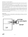
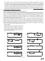
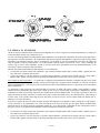
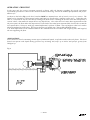
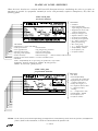
Indicatori di livello
Interruttori di livello
Strumenti pneumatici
DOMIZI Snc,
Te l +39 011 9457022
V ia Pole sine 15
Fa x +39 011 9457021
Level indicators
Level switches
Pneumatic instruments
10020 CAMBIANO
E -ma il : sa le [email protected]
TOR INO ITALY
w w w .domizi.com
Manuale
MDLBF 05-06
12-05
MANUALE DI ISTRUZIONI ALL’UTILIZZATORE
INSTALLAZIONE – USO – PRECAUZIONI
INSTRUCTION TO USER MANUAL
MOUNTING – OPERATING – CAUTION
INTERRUTTORE DI LIVELLO Mod. DLBF
LEVEL SWITCHES Type DLBF
Lo strumento viene prodotto in base alle specifiche
dell’acquirente e nel pieno rispetto delle Norme nazionali e internazionali sulla Qualità e Sicurezza. Viene
consegnato dalla fabbrica solo dopo aver superato i
controlli intermedi ed il collaudo finale; viene sempre
accompagnato dal presente Manuale generale, dal
Disegno tecnico che ne elenca le prestazioni
specifiche, e dal Certificato di prova che ne attesta il
collaudo individuale.
È pertanto pronto per essere installato sul serbatoio.
Le operazioni di installazione e di manutenzione
dovranno essere eseguite solo da personale adeguatamente preparato allo scopo.
Se vengono rispettati i dati riportati in questi documenti, lo strumento è certamente in condizione di assicurare prestazioni di alta qualità e di lunga durata.
Si consiglia perciò di porre la massima attenzione alle
istruzioni che seguono, integrandole con tutto ciò che
proviene dalla propria esperienza e dal buon senso
generale.
The instrument is manufactured on the basis of the
purchaser’s specifications and in the total conformity
of national and international standards about Quality
and Safety. It is delivered by the factory only after
having passed positively intermediate and final tests; it
is always accompanied by the present general Manual,
by the technical Drawing listing the specific
performances of it, and by the Test certificate stating
the individual final test of it.
Consequently it is ready to be installed on the vessel.
All the installing and maintenance operations shall be
made only by skilled personnel.
If purchaser effects the technical data reported in these
documents, the instrument is certainly in condition of
assuring high quality and long life performances.
We recommend to pay the max attention to the
following instruction, integrating them with all that
may come from your own experience and general good
sense.
Indice degli argomenti :
• Funzionamento e Targhe . . . . .
• Installazione : montaggio . . . . .
• Taratura
. . . . . . . . .
• Messa in funzione . . . . . . .
• Manutenzione: smontaggio/montaggio
• Problemi e soluzioni
. . . . .
• Disegno specifico dello strumento . .
Table of contents :
• Operation and Plates . . . . . . Page 9,10
• Installation : assembling . . . . . Page 11
• Calibration
. . . . . . . Page13
• Start up .
. . . . . . . . Page14
• Maintenance: dismantling/assembling
Page15
• Problems and solutions
. . . . Page15
• Specific drawing of instrument . . . Attached
. Pag. 2,3
. Pag. 4
. Pag. 6
. Pag. 7
. Pag. 8
. Pag. 8
. Allegato
1 – MDLBF
PRINCIPIO DI FUNZIONAMENTO
In questa pagina viene illustrato il principio di funzionamento dello strumento solamente in modo generico, mentre nel
Disegno tecnico allegato viene mostrato lo strumento specifico richiesto dall’acquirente, con tutte le caratteristiche e le
prestazioni nominali che è chiamato a realizzare.
Come illustrato nello schizzo e nella Fig. A più sotto, gli interruttori DLBF sono montati sul fianco di serbatoi
piuttosto stretti. Il livello del liquido viene controllato da un galleggiante solidale con un alberino , completo di una
strozzatura , molto flessibile;la spinta idrostatica proveniente dal galleggiante provoca una flessione dell’alberino
esterno e di conseguenza una spinta verticale che fa scattare il dispositivo (pneumatico DLBF5 o elettrico DLBF7)
d’uscita all’interno della custodia.
Quando il livello sale oltre il punto prestabilito, il galleggiante fa scattare il dispositivo, posto dentro la custodia
(intervento in salita); poi, quando il livello ridiscende al di sotto di tale punto, il galleggiante riporta il dispositivo allo
stato di partenza (ripristino in discesa); tra i punti di intervento e di ripristino vi è un differenziale di circa 5-10mm.
L’intervento avviene quando il liquido raggiunge all’incirca la linea mediana del galleggiante. È disponibile anche la
funzione contraria : Intervento in discesa e Ripristino in salita.
Un differenziale così piccolo è ottenibile agendo sulla combinazione tra volume e peso del galleggiante, e lunghezza
del braccio che sostiene il galleggiante.
APPLICAZIONI
Controllo di livello su serbatoi di vari liquidi industriali, in impianti petroliferi su piattaforme e su terra ferma.
L’interruttore DLBF può controllare il livello di liquidi con pressione fino al Rating 300, con temperature fino a 300°C
e con pesi specifici da 500 kg/m³ in su.
Fig.A
2 – MDLBF
TARGA SUGLI INTERRUTTORI
Targa ATEX /PED
per versione elettrica
•
•
•
•
•
•
•
•
SIGNIFICATO :
Nome e indirizzo del fabbricante
Codice strumento
• Numero di serie
Anno di produzione
• Sigla assegnata dal cliente
Temperatura ambiente
• Temperatura di processo
Pesi specifico del fluido
• Pressione massima
Assieme interruttore • Tipo di Mcroswitch • Portata elettrica del Microswitch
Volume del corpo strumento • Pressione e data di collaudo
Marchio CE 0948=Ente Notificato TUV che ha sorvegliato la produzione secondoPED:
Apparecchio : Gruppo II, Categoria IV
SIGNIFICATO :
• Marchio CE
• 0496 Ente Notificato che
sorveglia la produzione
Atex
• Apparecchio per zone
con atmosfera potenzialmente esplosiva
• Gruppo II, Categoria 1/2
• Miscela esplosiva : Gas
• E=Norme europee
• Ex=Protez. da esplosione
• dc= Custodia a prova d’espl.
sicurezza costrutt.
• IIC = Gruppo dei gas
• T.. = Classe temperatura
• Ente Notificato : KEMA
• 05 anno di certificzione
• Numero certificazione
Modulo: B (Esame CE di tipo) + Modulo: D (Allegato III – Sistema Qualità)
Targa ATEX / PED
per versione pneumatica
SIGNIFICATO :
• Marchio CE
• 0496 Ente Notificato che
sorveglia la produzione
Atex
• Apparecchio per zone
con atmosfera potenzialmente esplosiva
• Gruppo II, Categoria 1/2
• G = miscela esplosiva : Gas
• c = custodia a sicurezza
costruttiva
• T.. = Classe temperatura
• Ente Notificato : KEMA
• 05 anno di certificzione
• Numero certificazione
SIGNIFICATO :
• Nome e indirizzo del fabbricante
• Codice strumento
• Numero di serie
• Anno di produzione
• Sigla assegnata dal cliente
• Temperatura ambiente
• Temperatura di processo
• Pesi specifico del fluido
• Pressione massima
• Portata della valvola pneumatica
• Volume del corpo strumento • Pressione e data di collaudo
• Custodia stagna IP65 • Marchio CE 0948=Ente Notificato TUV che ha sorvegliato la produzione secondo PED:
Apparecchio : Gruppo II, Categoria IV
Modulo: B (Esame CE di tipo) + Modulo: D (Allegato III – Sistema Qualità)
NOTA – Nel caso di Indicatore di Livello operante a temperature tali da costituire pericolo di scottature per la
persona, viene aggiunta una targa di avvertimento sullo strumento.
3 – MDLBF
1 INSTALLAZIONE
Tutte le operazioni di ricezione e installazione dello strumento, devono essere affidate a personale di lunga esperienza,
e devono essere eseguite con i criteri della massima sicurezza, per evitare incidenti alle persone ed alle cose.
1.1 Disimballo dello strumento
Il trasporto fino alla destinazione finale, l’apertura della cassa di imballo ed il prelievo dello strumento dalla cassa
deve avvenire sempre con il criterio della salvaguardia dell’incolumità e sicurezza delle persone, e sempre e con
l’ausilio di appropriati mezzi di sollevamento, di guanti, occhiali, scarpe e vestiti previsti dalle Norme di Sicurezza.
Anche se lo strumento non presenta sporgenze o ruvidità tali da provocare tagli ed abrasioni, è normale prudenza
maneggiare tutto con molta cura e attenzione.
1.2 Collegamenti meccanici
Si raccomanda di operare sempre con la protezione di guanti, occhiali, scarpe e vestiti previsti dalle apposite Norme di
Sicurezza, e di usare sempre gli utensili più adeguati allo scopo. Tutte le operazioni dovranno essere eseguite solo da
personale adeguatamente preparato allo scopo. In particolare, per collegare lo strumento al serbatoio, bisogna :
• chiudere le valvole di intercettazione, in modo da interrompere il flusso del liquido da e verso il serbatoio;
• affacciare lo strumento ai punti di collegamento dell’impianto e poi fissarlo; si raccomanda di installarlo in modo
che la custodia rimanga con la targhetta dello strumento verso l’alto.
Bisogna adoperare tiranti, dadi, guarnizioni ed altri componenti di tipo adeguato alle prestazioni richieste
dall’impianto, e serrare i tiranti sulle flange con chiave dinamometrica opportunamente tarata a seconda di quanto
richiesto dal costruttore delle flange. Bisogna operare con la massima attenzione e controllare infine anche la tenuta
dei collegamenti eseguiti, allo scopo di evitare il rischio di successive perdite di liquidi in pressione, corrosivi, o
caldi/freddi, e perciò potenzialmente pericolosi per la salute umana e per l’ambiente (esplosioni e incendi).
1.3 Collegamenti pneumatici
Collegare i tubi dell’aria ai connettori dello strumento che si trovano sulla base della custodia. Bisogna impiegare solo
aria strumenti, cioè aria filtrata e depurata da umidità ed olio. Quest’aria dovrà entrare nel foro marcato IN, ed uscire
dal foro marcato OUT verso l’utilizzatore; i due fori sono filettati ¼” NPT-F.
Alla fine bisogna anche controllare che non ci siano perdite d’aria lungo i tubicini esterni alla custodia con l’impiego
ad es. di acqua saponata.
1.4 Collegamenti elettrici
Si raccomanda di operare sempre con la massima prudenza, per evitare pericolose scariche elettriche sulla persona e
anche danni potenzialmente ingenti sia all’impianto sia all’ambiente, come esplosioni ed incendi. L’impianto
elettrico, come d’altra parte tutto il resto dell’impianto, dovrà essere realizzato solo da personale qualificato che agirà
sul circuito solo dopo aver tolto tensione e dopo essersi accertato che nell’ambiente non vi è atmosfera esplosiva;
dovrà impiegare solo materiale certificato e adeguato alle esigenze dell’impianto (ad es. materiale stagno,
antideflagrante, etc). Una volta finiti i collegamenti, dovrà ripristinare le protezioni elettriche e meccaniche, in modo
da evitare contatti accidentali con parti sotto tensione
Ecco come collegare il microswitch al circuito elettrico.
• Sulla base della custodia : Togliere con un paio di pinze il tappo di plastica dal foro destinato al passaggio del cavo
elettrico; allentare con una chiave a brucola da 2mm la vite inox M4×10mm senza testa che si trova vicino al
suddetto foro : è un grano di sicurezza che serve ad evitare aperture accidentali del coperchio.
• Svitare il coperchio della custodia, agendo sulle due orecchie, a mano o con una leva e con delicatezza : la custodia
è in fusione di alluminio e potrebbe danneggiarsi se colpita con un martello.
• Sistemare il pressacavo ed il cavo entro il foro destinato al passaggio del cavo elettrico, accertandosi che venga
impiegato il modello richiesto dalle specifiche dell’impianto, sia come diametro, sia come filetto, sia come versione
dell’insieme (antifiamma, antideflagrante, etc) : la tenuta del foro dipende anche da questi elementi ed è essenziale
per la sicurezza dell’impianto. Verificare la tenuta del pressacavo subito dopo i collegamenti ed anche successivamente, secondo la periodicità indicata dal costruttore.
• Si arriva così alla morsettiera dei collegamenti elettrici . Vi sono 3 morsetti marcati NC, C, NO (Normalmente Chiuso, Comune, Normalmente Aperto) : quando il liquido sale oltre il livello stabilito, il microswitch apre
il contatto C-NC e chiude il contatto C-NO; quando il livello del liquido ridiscende al di sotto, il microswitch
ritorna allo stato di partenza. Se è presente il secondo microswitch, vi si ripete il tutto con azione simultanea.
• Collegare sull’apposito morsetto di terra anche il conduttore di protezione, per rendere equipotenziali le varie
masse dell’impianto, con questo accorgimento : sul morsetto interno alla custodia, il conduttore avrà una sezione
pari a quella dei conduttori collegati al microswitch, mentre sul morsetto esterno alla custodia, il conduttore avrà
una sezione di almeno 4mm².
• Effettuare i collegamenti elettrici secondo quanto richiesto dalle specifiche dell’impianto, usando solo pressacavi,
cavi e capicorda normalizzati.
4 – MDLBF
Se è possibile, si faccia in modo che l’intervento del microswitch scatti sia quando il galleggiante va nella posizione di intervento, sia nel caso che dovessero capitare eventuali anomalie nel circuito elettrico (ad es. rottura del
cavo, etc); in tal modo la segnalazione sul quadro elettrico attirerà l’attenzione dell’operatore per una riparazione
più tempestiva. Questo collegamento è indispensabile specialmente quando si opera su serbatoi contenenti liquidi
pericolosi : su di questi vanno montati due strumenti distinti, il 1° per l’intervento ad es. di Livello Alto, il 2° per
l’intervento di Livello Altissimo : qualora il primo dovesse andare in avaria, interviene certamente il secondo; si
ottiene così la massima sicurezza di funzionamento dell’impianto ed anche una manutenzione più attenta dei guasti.
• Riavvitare infine il coperchio della custodia e serrare bene il grano di sicurezza : questo è essenziale affinché lo
strumento lavori in condizioni di piena sicurezza !
Come proteggere la durata di vita di un contatto elettrico
È noto che al momento dell’apertura o della chiusura delle pastiglie di un contatto elettrico (che può essere un
microswitch, un interruttore manuale, un contatto reed, etc) in certe applicazioni può scoccare una forte scintilla tra di
loro. Se ripetuta nel tempo, questa scintilla provoca prima un rapido aumento/deterioramento della resistenza di
contatto, e poi una fine prematura di funzionamento del contatto stesso, con due possibili esiti sulle pastiglie : o non si
chiudono più (in realtà esse continuano a toccarsi ma non conducono più la corrente elettrica, a causa dei tanti crateri
scavati dalla scintilla) oppure non si aprono più (perché saldate tra di loro a causa dell’alta temperatura dovuta alla
scintilla e della pressione dovuta alla molla di scatto).
È anche noto che la scintilla è tanto più forte quanto più è induttivo o capacitivo il carico applicato al contatto elettrico.
Pertanto, per non accorciare eccessivamente la vita del contatto e compromettere così la sicurezza dell’impianto, si
impone il rimedio di limitare al massimo lo scoccare di tale scintilla. Suggeriamo qui di seguito alcuni accorgimenti.
I valori dei componenti da aggiungere sono da calcolare in base al carico elettrico da interrompere; alcuni di essi
mirano ad aumentare il cos ϕ dell’intero circuito al valore di 0,8-0,85 (rifasamento del circuito), altri ad assorbire
l’energia che si scaricherebbe sulle pastiglie mediante la scintilla.
Carico induttivo
Quando il carico è di tipo induttivo (motori, relé,
bobine, tubi fluorescenti non rifasati, etc), suggeriamo
di inserire uno dei seguenti circuiti di protezione, per
limitare l’extra-tensione e la conseguente scintilla che si
avrebbe durante l’allontanamento delle pastiglie, cioè
durante l’apertura del contatto.
~
~
M Vac
Vac
R
C
R
~
~
~
~
Vac
Vac
R
C
R
~
~
~
~
L
R
Vac
L
Lampada
Vac
Varistor
~
~
+
~
Lampada
Vdc
Vac
Diodo
-
~
5 – MDLBF
R
1.5 Funzionamento dello strumento
Lo strumento nella versione pneumatica assicura i seguenti funzionamenti :
• Apertura in salita e chiusura in discesa ( Fig.B )
Lo strumento opera così : quando il livello sale all’altezza stabilita, l’aria compressa viene aperta (ON), e quando
il livello ridiscende, l’aria viene chiusa (OFF).
• Chiusura in salita e apertura in discesa (Fig..C)
Lo strumento opera così : quando il livello sale all’altezza stabilita, l’aria compressa viene chiusa (OFF), e quando
il livello ridiscende, l’aria viene riaperta (ON).
Lo strumento nella versione elettrica assicura i seguenti funzionamenti :
Lo strumento opera così : quando il livello sale all’altezza stabilita viene rilasciato il microswitch ,e quando il
livello ridiscende provoca l’azionamento del microswitch.
1.6 Come invertire il funzionamento
I due funzionamenti possono essere invertiti facilmente, secondo le necessità dell’impianto.
Per la versione pneumatica è necessario ruotare lo strumento di 180° e procedere alla taratura come
riportato di seguito
Per la versione elettrica si agisce solamente sul collegamento elettrico invertendo le fasi .
1.7 Taratura
Sia se fatta in una vasca di prova sia se fatta direttamente sull’impianto, è assolutamente necessario che sia visibile il
galleggiante immerso.
1.7.1 Versione Pneumatica :
Apertura in salita e chiusura in discesa (Fig.B)
1.
2.
3.
Portare il livello del fluido a metà galleggiante assicurandosi che l’alimentazione dell’aria sia aperta.
Avvitare la vite a testa esagonale presente sull’alberino fino ad aprire l’uscita dell’aria dall’ugello del rele’.
Perfezionare la regolazione in questo modo : abbassare il livello del fluido fino a provocare la chiusura del
relé e fare in modo che in tale condizione il galleggiante non sia totalmente fuori dal fluido, ma che abbia
una piccola parte ancora immersa; in tal modo si avrà un buon margine di sicurezza.
Chiusura in salita e riapertura in discesa (Fig..C)
1.
2.
3.
Portare il livello del fluido leggermente oltre la metà galleggiante assicurandosi che l’alimentazione dell’aria sia
aperta.
Allentare la vite a testa esagonale presente sull’alberino fino a chiudere l’uscita dell’aria dall’ugello del relé .
Perfezionare la regolazione in questo modo : abbassare il livello del fluido fino a provocare la chiusura del
relé e fare in modo che in tale condizione il galleggiante non sia totalmente fuori dal fluido, ma che abbia
una piccola parte ancora immersa; in tal modo si avrà un buon margine di sicurezza.
1.7.2 Versione Elettrica (Fig.B) :
1 Portare il livello del fluido a metà galleggiante assicurandosi che ci sia l’alimentazione elettrica nel circuito.
2 Allentare la vite a testa esagonale presente sull’alberino fino ad azionare il microswitch.
3 Perfezionare la regolazione in questo modo : abbassare il livello del fluido fino a provocare il rilascio del
microswitch e fare in modo che in tale condizione il galleggiante non sia totalmente fuori dal fluido, ma che abbia
una piccola parte ancora immersa; in tal modo si avrà un buon margine di sicurezza.
6 – MDLBF
2.0 MESSA IN FUNZIONE
Anche la messa in funzione dello strumento sull’impianto deve essere eseguita con la massima attenzione, sempre per
evitare incidenti alle persone e danni alle cose.
Avviare con molta gradualità il riempimento dello strumento con il liquido da controllare, facendo la max attenzione a
non superare i valori di Pressione e di Temperatura indicati nel progetto dell’impianto e riportati nei dati di Targa dello
strumento e nel Disegno specifico che lo accompagna. In tal modo si avrà la possibilità di intervenire in tempo nel
caso di qualche svista nei collegamenti, e di evitare quindi rischi di danni a persone ed a cose. Sono comunque da
evitare colpi di ariete sullo strumento, perché se fossero molto forti, potrebbero provocare malfunzionamenti, e nei
casi limite il blocco completo dello strumento.
Durante il normale funzionamento dell’impianto si raccomanda di :
• Avvicinarsi con molta cautela allo strumento : può contenere liquidi molto caldi o molto freddi, e quindi può causare delle serie scottature alle persone.
• Aprire con cautela le valvole di spurgo e di sfiato dello strumento : possono uscire liquidi corrosivi, molto caldi o
molto freddi, oppure sotto pressione, e quindi potenzialmente pericolosi per l’uomo e per l’ambiente.
Cosa capita in caso di incendio ? Lo strumento è costituito principalmente di metallo e pertanto non può essere fonte
primaria di incendio; ed inoltre, quando richiesto dall’acquirente, vengono forniti strumenti in versione certificata
ATEX antideflagrante. Nel caso però che l’incendio provenisse dall’ambiente esterno, lo strumento in sé non subisce
danni significativi.
Lo strumento è stato realizzato con ampi margini di sicurezza, in modo che possa svolgere egregiamente i compiti
comunicati dal committente alla Domizi Snc, anche in caso di lievi sovraccarichi in pressione e temperature, purché
rientranti nei limiti previsti dalle Istruzioni di Collaudo delle Norme ASME/ANSI. Di norma si prevede la messa in
opera sul serbatoio di due strumenti, in modo che il primo esegua il normale lavoro di controllo (ad es. intervento per
Livello Alto), ed il secondo intervenga al posto del primo in caso di avaria e faccia scattare anche un allarme (ad es.
allarme per Livello Altissimo).
Se però, in seguito ad errori di manovra nella gestione dell’impianto, lo strumento venisse sottoposto a colpi improvvisi di pressioni e di temperature con valori totalmente al di fuori di quelli previsti dalle Norme ASME/ANSI,
potrebbe nascere il rischio di un suo cedimento strutturale; per evitare questo cedimento ed altre conseguenze ancora
più gravi al resto, il progettista dell’impianto realizza un adeguato sistema di protezione.
• Avvicinarsi con molta cautela allo strumento : può contenere liquidi molto caldi o molto freddi, e quindi può causare delle serie scottature alle persone.
• Aprire con cautela le valvole di spurgo e di sfiato dello strumento : possono uscire liquidi corrosivi, molto caldi o
molto freddi, oppure sotto pressione, e quindi potenzialmente pericolosi per l’uomo e per l’ambiente.
7 – MDLBF
Cosa capita in caso di incendio ? Lo strumento è costituito principalmente di metallo e pertanto non può essere fonte
primaria di incendio; ed inoltre, quando richiesto dall’acquirente, vengono forniti strumenti in versione certificata
ATEX antideflagrante. Nel caso però che l’incendio provenisse dall’ambiente esterno, lo strumento in sé non subisce
danni significativi.
Lo strumento è stato realizzato con ampi margini di sicurezza, in modo che possa svolgere egregiamente i compiti
comunicati dal committente alla Domizi Snc, anche in caso di lievi sovraccarichi in pressione e temperature, purché
rientranti nei limiti previsti dalle Istruzioni di Collaudo delle Norme ASME/ANSI. Di norma si prevede la messa in
opera sul serbatoio di due strumenti, in modo che il primo esegua il normale lavoro di controllo (ad es. intervento per
Livello Alto), ed il secondo intervenga al posto del primo in caso di avaria e faccia scattare anche un allarme (ad es.
allarme per Livello Altissimo).
Se però, in seguito ad errori di manovra nella gestione dell’impianto, lo strumento venisse sottoposto a colpi improvvisi di pressioni e di temperature con valori totalmente al di fuori di quelli previsti dalle Norme ASME/ANSI,
potrebbe nascere il rischio di un suo cedimento strutturale; per evitare questo cedimento ed altre conseguenze ancora
più gravi al resto, il progettista dell’impianto realizza un adeguato sistema di protezione.
3.0 MANUTENZIONE PERIODICA
3.1 Manutenzione meccanica
Nel tempo può rendersi necessaria la pulizia periodica delle parti interne dello strumento per liberarle da eventuali
depositi lasciati dal liquido sotto controllo; tale pulizia può essere eseguita indicativamente 1-2 volte all’anno, a
seconda del tipo di liquido. Si dovrà procedere nelle varie fasi con la massima attenzione, per evitare di correre rischi
per la salute delle persone (scottature, intossicazioni, etc) e per la salvaguardia dell’ambiente (esplosioni, incendi, etc).
In ogni caso, dopo aver indossato guanti, occhiali e vestiti adeguati, bisogna smontare lo strumento con queste fasi :
• Chiudere le valvole che intercettano l’entrata e l’uscita del liquido dallo strumento.
• Se necessario, attendere che l’intero strumento sia tornato alla temperatura ambientale, per evitare scottature.
• Se sono presenti sullo strumento, aprire con molta cautela la valvola di sfiato superiore e quella di drenaggio
inferiore, badando a ripararsi da eventuali spruzzi del liquido interno perché può essere corrosivo e pericoloso.
• Svitare i dadi dai tiranti delle flange e staccare con delicatezza lo strumento dall’impianto.
• Effettuare la pulizia interna dello strumento (con getti d’aria compressa, di vapore, etc).
• Alla fine rimontare il tutto, adoperando nuove guarnizioni sulle flange e procedendo nelle sequenza di sopra, ma
naturalmente in senso inverso.
• Riempire lo strumento nuovamente con il liquido da controllare e rimettere in funzione lo strumento.
3.2 Manutenzione pneumatica
Per evitare pericoli alla persona ed all’impianto pneumatico, si raccomanda di chiudere la condotta dell’aria compressa
dell’alimentatore del circuito.
Nel caso di sporcizia presente nell’alimentazione dell’aria si può verificare nel tempo il blocco del relè. In tal caso
procedere con molta attenzione smontando tutta la parte pneumatica, pulirla e rimontarla esattamente come prima.
3.3 Manutenzione elettrica
Per evitare pericolose scariche elettriche sulla persona e anche danni potenzialmente ingenti all’impianto ed anche
all’ambiente (esplosioni ed incendi), si raccomanda di agire con la massima prudenza e sempre dopo aver staccato la
tensione elettrica dal circuito ed essersi accertati che nell’atmosfera non ci siano miscele di gas esplosivi.
A seguito dell’usura del contatto elettrico, può essere necessaria la sostituzione del Microswitch;
il microswitch viene dato dalla casa costruttrice con una durata indicativa di 10.000 manovre con carico
elettrico nominale ; ma tale durata può accorciarsi notevolmente se il carico elettrico è più alto di quello nominale
oppure se è induttivo o capacitivo . Le operazioni da fare sono le stesse esposte nel par. INSTALLAZIONE a pag. 4 :
4.0 PROBLEMI E SOLUZIONI
•
•
-
Il liquido non solleva il galleggiante, oppure lo sommerge.
Forse lo strumento va sistemato ad un’altezza diversa sul serbatoio, oppure non è perfettamente orizzontale.
Il liquido è a livello sufficiente, ma non aziona il galleggiante.
Forse il galleggiante è danneggiato (deformato) : occorre sostituirlo..
• L’Interruttore opera al contrario di quello desiderato.
- Invertire la posizione di lavoro : ved. Punto 1.4 di questo Manuale d’istruzione.
• In caso di necessità di una riparazione, preghiamo interpellare direttamente la sede della Domizi Snc.
8 – MDLBF
OPERATION PRINCIPLE
In this page only the generic operation principle is shown, while the function regarding the specific instrument
requested by purchaser is shown in the enclosed Technical Drawing, with all the nominal specifications and performances of it.
As shown in the below Fig. A, the Level switches DLBF are mounted on a side of vessels, even if very narrow. The
liquid level is checked by a float integral with a small and very flexible tube ( complete with a neck ) ; within this tube
there is a rod fixed on only an end : the lift coming from float causes a bending on the outer tube and consequently a
vertical thrust , that makes the output device trip (trip on rise); then, when the level comes down again and exceeds
the preset point, the float makes the output device come back to the initial point (reset on fall); between the set and the
reset points there is always a small gap, named differential, of about 5-10mm. The trip happens when level reaches
about the median line of the float. The inverse function is available too : Trip on fall and Reset on rise.
A so small differential can be obtained thanks to the combination between volume and weight of float, and length of
the arm supporting the float.
APPLICATIONS.
Level control on vessels containing various types of industrial liquids, in off-shore and in-shore oil plants. The Level
Switch can operate with liquids having pressures up to Rating 300, temp. up to 300°C and specific gravity from
500kg/m³ up.
Fig.A
9 – MDLBF
PLATES ON LEVEL SWITCHES
When the Level Switches are certified ATEX 94/9/CE (European directive establishing the rules to get safety as
maximum as possible by equipments intended for areas with potentially explosive atmospheres), they have the
following plates.
ATEX / PED plate
for electric Switches
•
•
•
•
•
•
•
•
MEANING :
• CE Mark
• 0496 Notified Body
supervising the production
• Equipment for areas with
explosive atmosphere
• Group II, Category 1/2
• Esplosive mixture : Gas
• E=European standards
• Ex=Prot. from explosion
• dc= Safety constructive
flame-proof housing
• IIC = Gas group
• T… = Temperature class
• Notified Body : KEMA
• 05 Certificate year
• Cerificate number
MEANING :
Manufacturer’s name and address
Code of instrument
• Serial number
Year of production
• Tag assigned by purchaser
Ambient Temperature
• Process Temperature
Specific gravity of fluid
• Max Pressure of fluid
Switch Assembly
• Microswitch type
• Electric load of Microswitch
Volume of instrument chamber • Pressure and Date of test
CE Mark
0948 = Notified Body TUV supervising the production, as per PED :
Equipment : Group II, Category IV Module : B (CE type test) +
Module : D (Annex III – Quality System)
ATEX / PED plate
for pneumatic Switches
MEANING :
• CE Mark
• 0496 Notified Body
supervising the production
• Equipment for areas with
explosive atmosphere
• Group II, Category 1/2
• G= Explosive mixture Gas
• c =Apparatus safety
housing
• d• T… = Temperature class
• Notified Body : KEMA
• 05 Certificate year
• Cerificate number
NOTE - In the case of Level Switch operating at temperatures such that may cause burns on persons, an adjunctive
plate is fixed on the instrument, in order to caution about the possible risk.
10 – MDLBF
1 INSTALLATION
Every operations regarding receipt and installation of instrument, even if assigned to long experienced personnel, shall be
made with the norm of the maximum security, to avoid accidents to persons and things.
1.1 Instrument unpacking
Transport up to final destination, case opening and picking up of instrument from the case shall be made always with the
norm of protection and safety of persons, and always with the help of proper lifting means, of gloves, glasses, shoes and
clothes recommended by Safety Standards. Even if instruments have no protrusion or roughness, able to cause wounds and
abrasions, it is recommended to handle everything with the highest care.
1.2 Mechanical connections
We recommend to operate always with the protection of gloves, glasses, shoes and clothes listed by Safety Standards, and by
using the most proper tools. Every operations shall be made only by skilled personnel. In particular, to connect the
instrument to vessel, it is necessary :
• to shut off the cocks, in order to stop the flow from and to vessel;
• to put the instrument forward the connection points of the system and to fix it; we recommend to install it so that
housing remains with the plate direct towards high
It is necessary to use tie-rods, nuts, gaskets and other components absolutely suitable for the performances requested by the
system (named process too), and to tighten tie-rods on flanges with a dynamometric wrench, correctly calibrated according
to the instructions of flange’s manufacturer. It is also necessary to operate with the max attention and to check the seal of
these mechanical connections, in order to absolutely avoid the risk of subsequent liquid leaks : they may be under pressure
or corrosive or too cold/hot, and so may be potentially dangerous for human health and environment (fires and explosions).
1.3 Pneumatic connections
Connect the air pipes to the instrument connectors, placed on the outside base of housing. It is necessary to use only
instruments air, that is air already filtered and purified from moisture and oil. The air shall go in through the IN
union, and go out through the OUT union towards the user; the two holes are ¼” NPT-F threaded.
At the end it is also necessary to check that there is no air leak along the outside pipes, by wetting them, for example,
with soapy water.
1.4 Electric connections
We recommend to operate with the highest prudence, to avoid dangerous electric shocks on people and potentially huge
damages both on system and on environment, as explosions and fires.
The electric system, in the same way as other types of systems, shall be realized only by skilled personnel and only in
absence of tension on electric line and in absence of potentially explosive atmospheres, and will be made only by using
components being certified and suitable for the plant (e.g. flame-proof or water-proof materials certified, etc). After having
made connections, it is necessary to restore the mechanical and electric protections, in order to absolutely avoid casual
contacts with parts under tension.
How to connect the microswitch to electric circuit.
• On the housing base : With a pair of pincers remove the plastic protection cap from the electric connection
threaded hole. With a 2mm setscrew wrench loosen the stainless steel M4×10mm screw without head that you will
find near the electric connection threaded hole : it is a safety cone socket set screw that serves to avoid unintentional openings of housing.
• Unscrew the housing cover by acting on its two ears, by hand or by a lever, in soft manners : the housing is made
in aluminium casting and could be damaged if hit by a hammer.
• Place the cable-gland and the cable in the threaded hole for electric connections, after being sure that it corresponds to what requested by the specifications of the system, both as diameter and as threading and as version of
them (flame-proof, explosion-proof, etc) : the sealing of the hole depends on these elements too and is essential for
the safety of the system. Check the sealing of the cable-gland soon after the connections and also in subsequent
time, according to the instructions of the manufacturer.
• Now you will see the electrical connection terminal board Fig. 2 : there are 3 screws indicated with NC, C, NO,
(Normally Closed, Common, Normally Open) : when the liquid goes up more than the pre-set level, the microswitch turns off the contact C-NC and turns on the contact C-NO; when the level comes down again, the
microswitch comes back to the previous position. If a 2nd microswitch is present, everything is repeated on it with
simultaneous action.
• Connect the protective conductor to the specific grounding terminal, in order to make equipotential the various
masses of the system, with this attention : on the terminal inside housing, the conductor will have the same size
as those connected to microswitch, while on the terminal outside housing, the conductor will be at least 4mm².
• Make the connections according to what requested by the specifications of the system, by using only standardized
cable-glands, cables and eye cable terminals.
11 – MDLBF
If possible, try to obtain that microswitch trips both when float moves to operation position and also in the case of
possible failure in the electric circuit (for example, breaking of cable); in this way the indication on the control
panel will draw the attention of operator who will act also for a prompt failure repair. This type of connection is
essential especially on vessels containing dangerous liquids; on them two distinct instruments will be mounted, the
1st one for operation for example on High Level, the 2nd on for operation on Very High Level : in the case the 1st
one would go failed, the 2nd one will certainly operate; in this way you obtain the highest safety in the system
function and also a more attentive maintenance of failures.
• Screw again the cover on the base, and tighten the safety screw : only in these conditions the instrument can
operate in full safe conditions.
How to protect the life of an electric contact
As everybody knows, at the moment of opening or closing of an electric contact (of a microswitch, manual switch, reed
switch, etc) in certain applications a strong spark may happen between the two elements of the contact. If repeated in
the time, this spark causes in the first stages a quick worsening/increase of contact resistance, and then an untimely
work ending of the same contact, with two possible results on those elements : or they close no longer (they may touch
themselves, but do not conduct current any longer, because of so many craters dug by the spark), or they open no
longer (as welded each other because of the high spark temperature, and of the high release spring pressure).
We know also that the spark becomes stronger as the load connected to the electric contact becomes more inductive or
more capacitive.
Therefore, in order not to shorten the contact life too much, and not to compromise the system safety, it is necessary
and advisable to limit the spark priming as much as possible. We expose here some solutions.
The components values are to be calculated on the base of electric load to be switched off; some of them aim to
increase cos ϕ of the whole circuit up to 0,8-0,85 (power factor correction), other of them aim to absorb the energy
that would discharge by means of spark onto the elements of contact.
Inductive load
When the load is inductive (motors, relays, coils, etc),
we suggest one of the following protection circuits, in
order to limit the extra-voltage and the consequent
spark that would happen at the contact opening.
12 – MDLBF
Capacitive load
When the load is capacitive (capacitors, switching
supplies, filament and halogen lamps, etc), we
suggest one of the following protection circuits, in
order to limit the strong inrush current and the
consequent spark that would happen at the contact
closing.
1.5 How the instrument operates
The pneumatic version of the instrument performs the following functions :
• Open on rise and reclose on fall. ( Fig.B)
It operates as follows : when level rises up to the preset height, the compressed air is opened (ON), and when
comes down again, the air is reclosed (OFF).
• Close on rise and reopen on fall. (Fig.C)
It operates as follows : when level rises up to the preset height, the compressed air is closed (OFF), and when
comes down again, the air is reopened (ON).
The electrical version of the instrument performs the following functions :
It operates as follows: : when level rises up to the preset height the microswitch is deactivated and when the level
comes down again the microswitch is activated again.
The two functions can be easily reversed, according to the needs of the system.
1.6 How to reverse the function on the instrument
The two functions can be easily reversed, according to the needs of the system
For the pneumatic version is necessary sufficient to rotate the instruments of 180° and to proceed at the calibration as
explained in the next paragraph.
For the electrical version is sufficient to invert the phases of the electrical connection.
1.7 Calibration
Both if made in a test basin and if made directly on the system, it is necessary that the dipped float is well visible.
1.7.1 Pneumatic version
Open on rise and reclose on fall (Fig.B)
1. Fill the fluid up to half height of float and verify that air feeding is open.
2. Screw the hesagonal-head screw located on the flexible spindle up to open the air from the relay nozzle .
3. Make perfect the calibration this way : empty out the fluid up to cause the reclosing of air from the relay, and
act so that in this condition the float is not totally out of fluid, but a small part of it is still dipped; this way
you will have a good safety margin.
Close on rise and reopen on fall (Fig.C)
1. Fill the fluid up to a little bit more than the half height of float and verify that air feeding is open.
2. Unscrew the hesagonal-head screw located on the flexible spindle up to close the air from the relay nozzle .
3. Make perfect the calibration this way : empty out the fluid up to cause the reclosing of air from the relay, and
act so that in this condition the float is not totally out of fluid, but a small part of it is still dipped; this way you
will have a good safety margin.
1.7.2 Electrical version
1. Fill the fluid up to a little bit more than the half height of float and verify that air feeding is open.
2. Unscrew the hesagonal-head screw located on the flexible spindle up to activate the microswitch .
3. Make perfect the calibration this way : empty out the fluid up to cause the deactivated of the microswitch, and
act so that in this condition the float is not totally out of fluid, but a small part of it is still dipped; this way you
will have a good safety margin.
13 – MDLBF
2.0 START UP
Also the operations of starting up of instrument on process shall be made with the highest care, just to avoid accidents
to people and to things. In particular, we highly recommend to start very gradually the loading of instrument with the
liquid to be controlled, by paying the highest attention not to exceed the max values of Pressure and Temperature
reported on the Project of system, on the instrument Plate and on the specific Drawing accompanying the instrument.
This way the operator is in condition of immediately intervening in case of any mistake and thus avoid risks of
damages to people and to things. In any case water hammers on the instrument are absolutely to be avoided : if too
strong, they might cause uncertain functions and in the most severe cases also a total blocking of it.
During the normal function of plant, we recommend :
• To get near instrument very prudently : it may contain very hot or very cold liquids, and so may cause
serious burns to people.
• To open drain and vent valves of instrument with much caution : very dangerous liquids may come out (as very hot,
very cold, corrosive or under pressure) and may cause damages to people and to things.
What happens in case of fire ? The instrument is composed mainly by metal and so cannot be primary source of fire,
and furthermore, when requested by purchaser, instruments are supplied in ATEX certified flame-proof version. But
in the case that fire comes from outside environment, the instrument does not suffer significant damages.
The instrument has been realized with wide safety margin, so that can certainly assure the performances requested by
purchaser to Domizi Snc, even in the case of slight overloads in pressure and temperatures, on condition that they
come under the limits listed in the Test Instructions of ASME/ANSI Standards. In the usual cases two instruments are
used on the same vessel, so that the first one performs the normal control function (e.g. High level operation), and the
second one operates instead of the first in case of breakdown and activates also an alarm (High-High level alarm).
But in the case of important mistakes in process management, the instrument might be subject to sudden peaks of
pressures and temperatures having values totally out of those communicated in the order to Domizi Snc, and so it
might be subject to structural damages; just in order to avoid this damage and other much heavier effects on the
remaining parts, the plant designer realizes a proper and effective protection system.
14 – MDLBF
3.0 PERIODICAL MAINTENANCE
3.1 Mechanical maintenance
During the time a periodical cleaning of inside instrument from possible deposits may be necessary; according to the
type of liquids, cleaning could be made about 1-2 times a year. It is recommended to proceed in the various steps with
the highest care, to avoid risks for health of people (burns, poisonings, etc) and for environment protection (fires,
explosions, etc).
In any case, after having put on gloves, glasses and suitable clothes, would you please :
• Shut off the inlet and outlet cocks, in order to block the liquid to and from the instrument to be checked.
• If necessary, wait until the instrument come back to environmental temperature.
• If present on the instrument, open with much prudence the top vent valve and the bottom drain valve, taking
care to avoid splashes of inner liquid because potentially corrosive and dangerous.
• Unscrew the nuts from connection flanges, and remove the instrument from system with much care.
• Make the inner cleaning of instrument (with jets of compressed air, of steam, etc) and at then re-assemble
everything, by proceeding in the above sequence, but on the contrary.
• Fill very prudentially the instrument with the liquid and start up it
3.2 Pneumatic maintenance
In order to avoid dangers to people and to pneumatic system, we recommend to shut off the compressed air circuit.
In the case of impurities (e.g. oil, water, etc) in the air feeding it may happen that after time the relay stops working :
act with the max attention and dismantle the entire pneumatic device, clean it with care and assemble it exactly as
before.
3.3 Electrical maintenance
In order to avoid dangerous electric shocks to people, and also potentially huge damages to the plant and environment
too (explosions and fires), we recommend to act with the highest prudence and always after having turned off electric
voltage from the circuit and after having ascertain absence of potentially explosive gas mixtures in the atmosphere.
In consequence of wear of electric contact, it may be necessary to replace the Assembly with electric microswitch.
The microswitch is delivered by manufacturer for a life of 10.000 operations at nominal load ; but this life can be
remarkably shorter if the electric load is higher or inductive or capacitive . The operations are the same as exposed in
the para. INSTALLATION on page 11 :
4.0 PROBLEMS AND SOLUTIONS
•
•
•
-
The liquid does not push float upwards, or sink it.
Maybe the instrument should be placed at a different height on vessel, or is not perfectly vertical.
The liquid is at sufficient level, but does not push the float.
Maybe the float is damaged (cracked or deformed) : it should be replaced.
The Level switch operates on the contrary.
Inverse the operation position, as per above para. 1.4.
• If a repair is necessary, would you please contact the seat of Domizi Snc directly.
15 – MDLBF