1
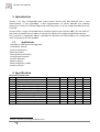
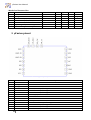
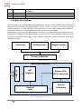
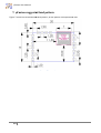
µFusion User Manual
µFusion
User Manual
Rev. 0.2 - May 2013
µFusion User Manual
Table of Contents
1.
Introduction ................................................................................................................................
................................
.................................. 3
1.1.
Applications ................................................................................................
................................
........................................................... 3
2.
Specification................................................................................................................................
................................
.................................. 3
3.
µFusion pinout ................................................................................................
................................
.............................................................. 4
4.
Engine description ................................................................................................
................................
........................................................ 5
5.
6.
1.2.
Axis assignment ................................................................................................
................................
..................................................... 6
1.3.
Factory calibration................................................................................................
................................
................................................. 6
1.4.
Magnetometer calibration ................................................................................................
.................................... 6
Communication ................................................................................................
................................
............................................................ 7
1.5.
UART ................................................................................................................................
................................
...................................... 7
1.6.
SPI ................................................................
................................................................................................
.......................................... 7
µFusion
Fusion Registers Description ................................................................................................
...................................... 8
WHO_AM_I (8 bit)................................................................................................
................................
............................................................ 8
CTRL_REG1 (8 bit) ................................................................................................
................................
............................................................ 9
CTRL_REG2 (8 bit) ................................................................................................
................................
............................................................ 9
ACC_NUMBER_AVG (8 bit) ................................................................................................
................................
............................................ 10
GYRO_NUMBER_AVG (8 bit) ................................................................................................
................................
.......................................... 10
MAG_NUMBER_AVG (8 bit) ................................................................................................
................................
........................................... 10
FLOAT_FIXED_REGISTER (32 bit) ................................................................................................
.................................... 10
OUT_Q1 (32 bit) ................................................................................................
................................
............................................................. 10
OUT_Q2 (32 bit) ................................................................................................
................................
............................................................. 11
OUT_Q3 (32 bit) ................................................................................................
................................
............................................................. 11
OUT_Q4 (32 bit) ................................................................................................
................................
............................................................. 11
OUT_Q_CHECKSUM (32 bit)................................................................................................
................................
........................................... 11
OUT_ROLL (32 bit)................................................................................................
................................
.......................................................... 11
OUT_PITCH (32 bit) ................................................................................................
................................
........................................................ 11
OUT_YAW (32 bit) ................................................................................................
................................
.......................................................... 12
OUT_ROLL_VEL(32 bit) ................................................................................................
................................
................................................... 12
OUT_PITCH_VEL (32 bit) ................................................................................................
................................
................................................ 12
OUT_YAW_VEL(32 bit) ................................................................................................
................................
................................................... 12
7.
µFusion
Fusion suggested land pattern ................................................................................................
................................. 13
2
µFusion User Manual
1. Introduction
µFusion is an easy configurable 9DoF AHRS system which mixes data coming from 3 axes
accelerometer, 3 axess gyroscope, 3 axes
ax s magnetometer to extract Attitude and Heading
References. Thanks to its shape,, weight and small dimensions, it can be easily embedded on every
kind PCB.
µFusion offers a range of communication interface options that includes UART, SPI and USB 2.01
with which is possible to have access to several I/O registers for configuration and data output.
output
Every µFusion is individually factory calibrated
calib
but provide the functionality to be recalibrated
when mounted on the final product.
1.1.
Applications
· Helicopters,
rs, quadrotors and flying
flyi UAV
· Underwater vehicles
· Camera stabilization
· Balancing robots
· Gaming and virtual reality
· Compensated compass
· Position detection
· Motion capture
· Robot navigation / SLAM
· Antenna control
2. Specification
Electrical characteristics
Symbol
Vdd
Idd
VIH(UART)
VIL(UART)
VIH(SPI)
VIL(SPI)
VOH
VOL
Ton
fUART
fSPI
1
Parameter
Supply voltage
Current consumption
Digital high level input voltage (UART)
Digital low level input voltage (UART)
Digital high level input voltage (SPI)
Digital low level input voltage (SPI)
High level output voltage
Low level output voltage
Turn on time
UART communication frequency
SPI communication frequency
USB 2.0 is available only through the motherboard.
3
Test condition
Min
3.2
Vdd = 5V
1.7
-0.3
1.8
-0.3
2.4
Typical
5
23
3.0
Max
6
5.5
0.9
3.3
0.9
3.2
0.4
0.8
115200 115200 921600
16
Unit
V
mA
V
V
V
V
V
V
s
baud/s
Mbit/s
µFusion User Manual
Mechanical characteristics
Symbol
Dim
W
AY
AR,P
fout
Trange
ωmax
Parameter
Dimensions
Weight
Static accuracy (Yaw)
Static accuracy (Roll,, Pitch)
Pitch
Maximum output rate
Operating temperature range
Maximum angular velocity
Test condiction
Min
-20
3. µFusion pinout
Figure 1. µFusion pinout.
Pin
1
2
3
4
5
6
7
8
9
10
11
12
13
14
Name
GND
UART_TX
UART_RX
RES
RES
RES
VCC
GND
GND
INT
NC
RES
RES
GND
4
Description
Ground.
TTL Uart trasmitter.
TTL Uart receiver.
Reserved. Leave pin floating.
Reserved. Leave pin floating.
Reserved. Leave pin floating.
Power supply.
Ground.
Ground.
Interrupt.
Not connected. Leave pin floating.
Reserved. Leave pin floating.
Reserved. Leave pin floating.
Ground.
Typical
15x20
3
1.5
0.5
190
20
Max
60
2000
Unit
mm2
g
°
°
Hz
°C
°/s
µFusion User Manual
15
SPI_CS
16
17
18
SPI_CLK
SPI_MISO
SPI_MOSI
SPI chip select (0: SPI communications, 1:: UART communications).
communications) This pin is
5V tolerant.
SPI clock.
SPI serial data output.
SPI serial data input.
4. Engine description
filter that takes
µFusion works as an Attitude and Heading References System. It uses a Kalman filter,
accelerometer, gyroscope and magnetometer data as input, in order to estimate a drift-free
attitude reference in a 360° 3D space with high accuracy in both static and dynamic conditions.
conditions
The Kalman filter runs in a 32-bit
bit ARM processor at the frequency of 190Hz.
Accelerometer, gyroscope and magnetometer are factory calibrated, but run
run-time calibrations for
magnetometer and gyroscope are provided. Gyroscope biases are automatically calibrated during
the normal operations of the engine,
engine while magnetic calibration is active only when selected by
the specific register.
Gyroscope
Accelerometer
Magnetometer
Factory calibration
UART / SPI
ARM 32bit Processor
I/O
Registers
Controll
Unit
Figure 2. µFusion high level schematic.
5
Kalman Filter
(RPY estimation)
Sensors
Calibration
µFusion User Manual
1.2.
Axis assignment
µFusion uses the ENU (East, North, Up) fixed reference system. In this representation, the X axis
points to East, the Y axis points
point to North and the Z axis points Up. Every output rotation is
expressed according to this reference.
In Figure 3 it is shown how this representation has been fixed on µFusion.
Figure 3.µFusion axis assignement
1.3.
Factory calibration
The data coming from the three sensors are not usable as soon as acquired. Thess
The measures are
affected by different types of errors. Two main errors affect mostly the real measured value: offset
and scale factor. Offset is the constant error between
between the measured value and the known value
(typically the 0), whereas the scale factor represents
represent the variation of the during the increase of the
distance from the zero. So it’s possible to assume that:
∙ where Vreal is the real value and Vmeas is the measured value. For every sensor, the values of offset
and scale are estimated during the factory calibration process, stored into µFusion
Fusion and applied for
every acquisition.
1.4.
Magnetometer calibration
Any magnetic sensor is influenced by hard-iron and soft-iron interferences.
Hard-iron
iron interference is due to permanent magnets or magnetized iron and steel, that are
present around the sensor and create a magnetic field that is added directly to the Earth’s
magnetic field.
Soft-iron
iron interference is caused by all the items around the magnetometer which are composed by
iron material which distorts the direction of the Earth’s magnetic field.
In order to obtain better results
result in the Heading estimation, these two factor have to be
compensated. The algorithm running on µFusion allows to compensate these distortions
distortion and
provides a magnetometer calibration to estimate them.
6
µFusion User Manual
When µFusion
Fusion is placed in a new system, it’s highly suggested to run at least once the
magnetometer calibration.
alibration. To run the calibration, just set to 1 the M_CAL of the CTRL_REG_1 and
rotate the entire system, preferably as if you were tracing some eight-shapes
shapes in the air. After the
calibration is completed,, the bit M_CAL is automatically set to 0.
5. Communication
The interface with the board is composed by several I/O registers which allow to set the desired
configuration and acquire the output values. You can access to these registers can be done
through the UART and the SPI interfaces.
interface In the sections below, it is described how to have access
to the I/O registers.
1.5.
UART
µFusion permits to communicate through the universal asynchronous receiver/transmitter (UART)
and uses a communication protocol to read and write the I/O registers. The interface uses two
lines:: Tx serial input and Rx serial output. The Tx high output voltage is at 3.0 V and the Rx input
accepts voltage from 1.7V to 5.5V.
The UART interface uses 8N1 (8 data bits, no parity, 1 stop bit) format and supports the following
standard baud rates: 115200, 230400, 460800, 921600. The default baud rates is set to 115200
and can be changed by using the CTRL_REG1.
At the beginning, µFusion
Fusion works as slave waiting for a command. There are two types
type of
commands that µFusion
Fusion accept: register write command and register read command. These two
commands allow to read and write I/O register.
The read command starts with the hash symbol “#” followed by “R”, the number of the register in
ASCII format and the number of consecutive register to be read that is also in ASCII format:
format
#
R
Number of register
Consecutive
the value of Number of register and Consecutive are always expressed by two characters.
The answer to this command is the following:
follow
#
R
Value 1
Value 2
Value…
where Value 1, Value 2, etc… are the binary values requested by the read command.
The write command starts with the hash symbol “#” followed by “W” and the number of the
register in ASCII format:
#
W
Number of register
Value
the value of Number of register and Value are always expressed by two characters.
1.6.
SPI
The SPI (Serial
Serial Peripheral Interface)
Interface is a synchronous serial communication standard that is
commonly supported by many micro-controllers
micro
and other embedded systems. The SPI standard
defines 4 different working modes,
mode µFusion uses the Mode 3.
The SPI interface uses four liness:: MISO (master input slave output), MOSI (master output slave
input), CLK (clock) and CS (chip select). The maximum voltage accepted by the four lines is 3.3V.
SPI read/write operations are completed in 16 or more clock cycles. The first byte is sent from the
master to µFusion and contains the address of the register and the following bytes containing
contain the
register data. The first bit of the
he register address is the R/ W bit and it iss used to indicate the
Read (1) or Write (0) operation. During the data transmission, the big endian convention is used.
7
µFusion User Manual
Figure 4 Errore. L'origine riferimento non è stata trovata. and Figure 5 show respectively
examples of reading and multireading operations,
operation while Figure 6 shows an example of writing
operation.
Figure 4. SPI reading.
Figure 5. SPI multireading.
Figure 6. SPI writing.
To avoid communications problems, some time constrain have to be respected.
Symbol
Parameter
Tcomm Time between two SPI communications.
Tbyte
Time between two
6. µFusion
Fusion Registers Description
WHO_AM_I (8 bit)
Who am I.
Address: 0x00.
8
Min
3
8
Max
Unit
µs
µs
µFusion User Manual
WHO_AM_I
WHO_AM_I
0xA5
CTRL_REG1 (8 bit)
Control register 1.
Address: 0x01. Default: 0xC8.
PW
M_EN
M_CAL
M_CAL_RES INT_DRDY
UART_SP1
UART_SP2
PW
Power Mode. Default: 1
0: Power down
1: Power on
M_EN
Magnetometer enable. Default: 1.
0: Magnetometer disabled.
1: Magnetometer Enabled.
M_CAL
Magnetometer calibration. When this bit is set to 1, the magnetometer calibration starts
start
running. When the magnetometer calibration is stopped, this bit is automatically set to 0.
Default: 0.
0: Magnetometer calibration is not running.
1: Magnetometer calibration is running.
M_CAL_RES Magnetometer calibration result. At the end of the magnetometer
magnetometer calibration, if this bit is
set to 1 it is successful and 0 otherwise.
INT_DRDY
Interrupt activation an INT1 pin when a new data is ready. Interrupt is active high. Default: 1.
0: Interrupt disabled.
1: Interrupt enabled.
UART_SP1
UART communication speed. As soon as the value of these registers has changed, the UART
UART_SP2
starts to communicate with the new speed.
UART_SP1
0
0
1
1
UART_SP2
0
1
0
1
Speed (Baud/s)
115200
230400
460800
921600
CTRL_REG2 (8 bit)
Control register 2.
Address: 0x02. Default: 0x00.
CQ_SEND
CQ_SEND
CKS_SEND
CRPY_SEND
0
0
0
F_OUT1
F_OUT2
Continues quaternion sending. When this bit is set, µFusion sends automatically via UART
the four quaternions as soon as updated. This function is not available during SPI
communications.
CKS_SEND
When CQ_SEND = 1 and this bit is set to 1, also the quaternions checksum is automatically
sent.
CRPY_SEND Continues RPY sending. When this bit is set, µFusion
Fusion sends automatically via UART the Roll,
Pitch and Yaw as soon as updated. This function is not available during SPI communications.
9
µFusion User Manual
F_OUT1
F_OUT2
F_OUT1
0
0
1
1
Output data rate. This bits are used only when CQ_SEND or CRPY_SEND are set.
F_OUT2
0
1
0
1
Freq (Hz)
190
95
50
25
ACC_NUMBER_AVG (8 bit)
Number of average applied on the accelerometer raw data.
Address: 0x08. Default: 0x01.
N_AVG_ACC
N_AVG_ACC Number of average value represented as unsigned integer.
GYRO_NUMBER_AVG (8 bit)
Number of average applied on the gyroscope raw data.
Address: 0x09. Default: 0x01.
N_AVG
N_AVG_GYRO Number of average value represented as unsigned integer.
MAG_NUMBER_AVG (8 bit)
Number of average applied on the magnetometer raw data.
Address: 0x0A. Default: 0x01.
N_AVG
N_AVG_MAG Number of average value represented as unsigned integer.
FLOAT_FIXED_REGISTER (32 bit)
Fixed float register. This register contains a fixed value and can be useful to set the right method
to acquire data.
Address: 0x10.
FLOAT_FIXED_REGISTER
FLOAT_FIXED_REGISTER -9854.328125
28125 (-9854,215)
OUT_Q1 (32 bit)
Value of quaternion 1.
Address: 0x11.
10
µFusion User Manual
OUT_Q1
OUT_Q1
Quaternion value represented as floating point.
OUT_Q2 (32 bit)
Value of quaternion 2.
Address: 0x12.
OUT_Q2
OUT_Q2
Quaternion value represented as floating point.
OUT_Q3 (32 bit)
Value of quaternion 3.
Address: 0x13.
OUT_Q3
OUT_Q3
Quaternion value represented as floating point.
OUT_Q4 (32 bit)
Value of quaternion 4.
Address: 0x14.
OUT_Q4
OUT_Q4
Quaternion value in floating point.
point
OUT_Q_CHECKSUM (32 bit)
Value of quaternion checksum.
Address: 0x15.
OUT_Q_CS
OUT_Q_CS
Checksum for the values of the four quaternions.
It is calculated as the xor of the four quaternion values.
OUT_ROLL (32 bit)
Value of roll angle in degree.
Address: 0x16.
OUT_ROLL
OUT_ROLL
Roll value represented as floating point.
OUT_PITCH (32 bit)
11
µFusion User Manual
Value of pitch angle in degree.
Address: 0x17.
OUT_PITCH
OUT_PITCH Pitch value represented as floating point.
OUT_YAW (32 bit)
Value of yaw angle in degree.
Address: 0x18.
OUT_YAW
OUT_YAW
Yaw value represented as floating point.
OUT_RPY_CHECKSUM (32 bit)
Value of RPY checksum.
Address: 0x19.
OUT_RPY_CS
OUT_RPY_CS Checksum for the values of roll, pitch and yaw.
It is calculated as the xor of the three RPY values.
OUT_ROLL_VEL(32 bit)
Value of roll velocity in degree.
Address: 0x1A.
OUT_ROLL_VEL
OUT_ROLL_VEL Roll velocity value represented as floating point.
OUT_PITCH_VEL (32 bit)
Value of pitch velocity in degree.
Address: 0x1B.
OUT_PITCH_VEL
OUT_PITCH_VEL Pitch velocity value represented as floating point.
OUT_YAW_VEL(32 bit)
Value of yaw velocity in degree.
Address: 0x1C.
OUT_YAW_VEL
OUT_YAW_VEL Yaw velocity value represented as floating point.
12
µFusion User Manual
7. µFusion suggested land pattern
Figure 7 shows the recommended land pattern, all the quotes are expressed in mm.
Figure 7. Suggested land pattern.
13