1
Table Of
Content
1. Overview
2. Main features
3. Software installation and setup
3.1. Windows installation
3.2. Linux installation
3.3. Solaris installation
4. Getting started
5. Selecting a device
FLIP User’s
Manual
6. Selecting a communication medium
6.1. RS232
6.2. CAN
7. Device special bytes
7.1. General options
7.2. CAN options
8. Editing the buffer and setting options
8.1. The Edit Buffer window
8.2. The Buffer options window
8.3. The Buffer Checksum
9. Executing operations on the target device
10. Operations flow
11. The history and command window
12. Recording and replaying commands
12.1. Building the configuration file from FLIP
12.2. Loading and running the configuration file
12.3. Building a configuration file using a text editor
12.4. Configuration file example
13. Troubleshooting
13.1. Global messages
13.2. CAN messages
13.3. RS232 messages
Overview
This ATMEL’s ISP software allows to program all our
FLASH C51 parts. It runs under Windows 9x / Me, Windows NT / 2000 / XP and Linux as well.
Rev. xxxxE–8051–02/02
1
Communicating with the target device may be done through a RS232 link, a CAN or an
USB link, depending on the communication media supported by the target device.
This software is named FLIP, which stands for: FLexible In-system Programmer.
Main Features
•
Intel MCS-86 Hexadecimal Object, Code 88 file format supported for data file
loading and saving
•
Optional address offset for loading
•
Buffer control:
–
•
data byte modification, address range fill-in, goto a specified address, data
byte sequence search
Target device control:
–
Blank check, Program, Read, Verify, Erase, Special bytes edition capability
•
Permanently displayed and updated information about the buffer options and the
target device status
•
Customizable flow for quick repeating programming
•
Command window allowing control through a command file (Tcl language)
•
Commands recording for automatic reconfiguration and commands replay.
•
Progress bar, tooltips and on-line help
•
Copy the Flip_<version>.zip file to an empty temporary directory.
•
Perform the zip file extraction so that it builds a Flip_<version> directory.
•
Open the Flip_<version> directory and run the Setup file.
•
Follow the installation program instructions.
Software Installation
and Setup
Windows Installation
For parallel port to CAN interfaces to work, you have to install the proper drivers first.
Linux Installation
Uncompress and untar the archive file.
The Linux version of FLIP supports ISP through the RS232 port and RS232 / CAN interfaces (nor USB, neither parallel port CAN interfaces are supported).
2
xxxxE–8051–02/02
Getting Started
This chapter guides you through a short tour of FLIP to help you getting started with this
ISP software.
Once the FLIP main window appears, you can see three areas from the left to the right:
the Operations Flow area, the Buffer Information area and the Device parameters one.
Just below these three frames stands a command and history window which use will be
discussed in Section “The history and command window”, page 8.
A message log window, a progress bar area and a communication information report
are available at the bottom of the main window.
1. Connect your target hardware to the host platform serial port, CAN port or USB
one.
–
Connect your target hardware to a power supply and reset it. We assume
that the device to be programmed contains a FLIP compliant bootloader
program.
2. Select a device from the device list.
–
From the top menu bar, select the Device item. In the Device pull-down
menu, click the Select item.The Device Selection dialog box pops up. Select
a device from the devices list box and click OK.
As soon as the device is selected, the Device parameters area is updated to
let you see the selected device special bytes. The Buffer information area is
updated as well with device dependent information.
3. Select a communication medium.
–
From the top menu bar, select the Settings item. In the Settings pull-down
menu, click the Communication item. In the Communication cascading
menu, select a communication medium.
The medium setup dialog box pops up. Adjust the communication
parameters, and click Connect.
FLIP starts a synchronization sequence with the target device bootloader
software. After the synchronization sequence completion, FLIP reads the
target device special bytes and updates the main window frame on the right.
4. Select a HEX data file.
–
From the top menu bar, select the File item. In the File pull-down menu, click
the Load item.
Select a HEX file from the file browser. FLIP parses the HEX file and fills in
the edition buffer.
5. Open the buffer edition window.
–
From the top menu bar, select the Buffer item. In the Buffer pull-down menu,
click the Edit item.
The Edit Buffer window pops up. You may now perform many operations
onto the buffer contents.
For details about the possible buffer editing capabilities, see the
Section “Editing the buffer and setting options”, page 5.
6. Open the buffer options window.
–
You may open the buffer options window from the FLIP main window, or from
the Edit Buffer dialog box.
From the main window menu bar, select the Buffer item. In the Buffer pulldown menu, click the Options item.
The Buffer Options dialog box pops up. The main buffer options are: the
buffer size, the initial contents, the address programming range and the
3
xxxxE–8051–02/02
loading offset. For details about these options, see the Section “Editing the
buffer and setting options”, page 5.
7. Program the target device.
–
From the top menu bar, select the Device item. In the Device pull-down
menu, click the Program item.
This concludes our short tour of the FLIP demo. For detailed descriptions of the possible
operations, please read the following chapters.
Selecting a device
From the top menu bar, select the Device item. In the Device pull-down menu, click the
Select item.The Device Selection dialog box pops up. Select a device from the devices
list box and click OK.
As soon as the device is selected, the Device parameters area is updated to let you see
the selected device special bytes. The Buffer information area is updated as well with
device dependent information.
The device selection may be done by pressing the F2 function key.
Each device supports a particular set of communication media.
You may use FLIP as an HEX file editor only; in that case, you do not have to select a
device from the device list.
Selecting a
communication
medium
From the top menu bar, select the Settings item. In the Settings pull-down menu, click
the Communication item. In the Communication cascading menu, select a communication medium. The medium setup dialog box pops up.
RS232
Adjust the communication parameters, and click Connect.
FLIP starts a synchronization sequence with the target device bootloader software. After
the synchronization sequence completion, FLIP reads the target device special bytes
and updates the Device parameters area.
The communication medium selection may be done by pressing the F3 function key.
Important note:
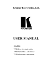
The RS232 synchronization sequence will probably pass, even at high baudrates. Nevertheless, you must take care to the baudrate selection: if the target hardware oscillator
frequency is too low, the bootloader cannot achieve characters reception/transmission
and FLASH programming properly. In such cases, you have to decrease the baudrate.
FLIP will warn you through a message box if such a situation occurs. The following table
shows the valid Osc. freq./Baudrate pairs which allow a successful RS232 transmission.
Freq. / Baudrate
2400
4800
9600
19200
38400
11.0592 MHz
3
3
3
3
3
12.0000 MHz
3
3
3
3
3
14.7456 MHz
3
3
3
3
3
16.0000 MHz
3
3
3
3
3
22.1184 MHz
3
3
3
3
24.0000 MHz
3
3
3
3
57600
115200
3
3
3
3
3
3
3
3
4
xxxxE–8051–02/02
CAN
•
Select the proper CAN interface from the pulldown CAN menu. FLIP supports
several CAN interfaces: three of them must be connected to the PC parallel port,
one of them has been developed by ATMEL and must be connected to the PC
RS232 port; the last one is an USB to CAN interface.
–
The Controller Area Network Setup dialog box shows up.
•
Adjust the communication parameters port and baud rate.
•
Click the Init button; this initializes the CAN hardware interface connected to the
PC.
•
Check the node number and the CRIS parameters values; change them if
necessary. For the CRIS parameter to be taken into account, you must hit the
RETURN key after typing the new CRIS value; this updates the IDs values
displayed in the dialog box.
–
Click the Node Connect button. FLIP reads the target device special bytes
and updates the Device parameters area.
Device special bytes
General options
The device special bytes are displayed in the main window Device parameters area.
Some of them are read-only.
You may read the special bytes at any time, if allowed by the security level, by clicking
the Read button.
Changing the special bytes values is straight forward: set a new value in the proper
entry field and click the Set button.
FLIP will write the special bytes new values and will read back the special bytes values
from the device. This guaranties that the displayed values are the device ones, not only
values to be programmed.
FLIP takes care about the current security level and disables the Read and the Set buttons when necessary.
CAN options
For devices supporting the CAN protocol, FLIP provides a CAN button at the bottom of
the Device parameters area.
Clicking the CAN button makes the CAN Node Configuration dialog visible. It lets you
read and modify a CAN node parameters.
The parameters that may be changed are :
•
node number
•
CRIS (CAN Relocatable Identifier Segment)
•
BTC1 / BTC2 / BTC3 (Byte Timing Configuration)
To change a value, simply type the new value in the proper entry and click the Set
button.
After any CAN node configuration modification, you must reset the target device in order
to force the new configuration to be taken into account.
Editing the buffer and
setting options
FLIP allows many operations on the buffer. This chapter describes each of them.
The Edit Buffer window
From the top menu bar, select the Buffer item. In the Buffer pull-down menu, click the
Edit item.
5
xxxxE–8051–02/02
The entries are not case sensitive. Nor X, neither 0X prefix is necessary when you type
addresses or data values.
•
File > Load ...
–
•
File > Save as ...
–
•
•
–
Opens a dialog box which lets you modify the buffer contents. Type an
address and a data value in hexadecimal format.
After modification, the buffer window is scrolled and a yellow tag highlights
the modified address. You may perform buffer modifications by merely
double-clicking a data byte within the buffer window.
–
Click the Apply button to perform changes without closing the Modify Buffer
dialog box. Click the OK button or hit the Return key to perform changes
and close the dialog box.
Edit > Goto ...
•
•
Use this command to reset the buffer to the default blank value. The default
blank value is displayed in the main window Buffer Information area. You can
change it by using the Buffer Options window.
Device > Read
–
•
Lets you enter a start address, an end address, and a value you want to be
used to fill the defined address range.
Click the Fill button to fill the address range. Use the Check button when
you want to check an address range contents.
Edit > Reset ...
–
•
Opens a dialog box which lets you specify an address you want to scroll to.
Edit > Fill ...
–
•
Allows saving the buffer contents to a file.
The range of addresses which will be saved is recalled in the main window
Buffer Information area, with the Range label. You may modify the range
values through the Buffer Options dialog box. In the Address Programming
Range field, select the User Defined Address Range option and set the
Min and Max addresses, then click OK or Apply. The main window Buffer
Information area should reflect your changes.
Edit > Modify ...
–
•
Loads a HEX file into the buffer. Use the file browser to select a file.
Use this command to read the target device FLASH memory. The Edit Buffer
window is updated afterwards.
Device > Program
–
Use this command to program the target device FLASH memory.
–
The device programming address range is displayed in the main window
Buffer Information area and is labeled Range. You can change it by using
the Buffer Options window.
Device > Verify
–
This command lets you compare the target device memory contents with the
buffer one. The comparison is done between (and including) boundary
addresses. The address range is displayed in the main window Buffer
Information. You can change it by using the Buffer Options window.
–
FLIP displays the first fail address, if any.
Options ...
–
This command opens the Buffer Options dialog box.
6
xxxxE–8051–02/02
The Buffer options
window
From the top menu bar, select the Buffer item. In the Buffer pull-down menu, click the
Options item.
The entries are not case sensitive. Nor X, neither 0X prefix is necessary when you type
addresses or data values.
•
Buffer Size
–
•
Initial Buffer Contents
–
•
This option lets you define the address range which will be used to program
the target device. It can be set to the following values:
Address Range From Last Buffer Load
–
This is the default setup. The address programming range is set to the
address range of the last HEX file loaded into the buffer.
•
Whole Buffer
•
User Defined Address Range
–
–
•
The whole buffer address range will be used to program the target device.
Select this option if you want to define a particular range of address to
program the target device.
Loading Address Offset
–
The Buffer Checksum
Set this option to yes only if you want the buffer to be reset to the blank value
before reading the HEX file.
The default No value is useful when you intend to load several HEX files into
the buffer.
Address Programming Range
–
•
After a device selection, this option is set to device dependent state by
default; this means that the buffer default reset value is set to the target
device memory blank value.
You may override this option setup and define a different buffer reset value.
Reset Buffer Before Loading
–
•
After a device selection, this option is set to device dependent state by
default; this means that the buffer size is set to the target device memory
one (in Kbytes).
You may override this option setup and define a different buffer size value.
This field lets you enter an offset value to be added to the HEX file
addresses before loading the buffer.
The buffer checksum value is displayed in the main window Buffer Information area.
The checksum is calculated on the address range displayed in the Buffer Information
area; the address boundaries are included in the address range. As described in the
above paragraph, the user has control over the address programming range.
The checksum value is updated each time the buffer is modified within the address programming range by operations like: reset, modify, fill, HEX file loading and device
reading.
Executing operations
on the target device
From the top menu bar, select the Device item. In the Device pull-down menu, select an
operation.
•
Device > Select ...
–
•
Use this command to select a device from a list.
Device > Erase ...
7
xxxxE–8051–02/02
–
•
Device > Blank Check ...
–
•
This command launches the target device programmation. The device
programming address range is displayed in the main window Buffer
Information area and is labeled Range. You can change it by using the
Buffer Options window.
Device > Verify
–
Operations flow
This command lets you read the target device contents between two
boundary addresses. You can specify these boundaries through the dialog
box Start address and End address fields.
Device > Program
–
•
This command lets you compare the target device contents to the blank
value. The current blank value is displayed in the Buffer Information area of
the main window. The verification is done between (and including) two
boundary addresses which you can adjust through the Blank Check dialog
box Start Address and End Address fields. Click the Check button to
perform the operation. The pass/fail status is displayed in the Blank Check
dialog box. If an error occurs the fail address is reported in the Blank Check
dialog box.
Use the dialog box Reset button to clear any previous check status
message.
Device > Read ...
–
•
This command pops up a dialog box for you to enter the erasing options.
Some devices do not allow erasing per block; FLIP takes care about this by
making the corresponding selections impossible.
This command lets you compare the target device contents to the buffer one.
The verification is done on the address range displayed in the main window
Buffer Information area and is labeled Range. You can change it by using
the Buffer Options window.
The operations flow is displayed on the left part of the FLIP main window. It lets you
select a number of operations to be performed sequentially. You launch the flow
sequence by clicking the Run button.
When an operation completes, the corresponding check box color changes from white
to green (for pass status) or red (for fail status).
If one of the operations fails, the operations flow stops.
Some operations in the flow require that you perform a setup, first :
•
Erase - Setup the erase options through Device > Erase ...
•
Blank Check - Setup the Blank Check options through Device > Blank Check ...
•
Program - Setup the address programming range through Buffer > Options ...
•
Verify - Setup the address verifying range through Buffer > Options ...
Use the Clear button to clear all checkboxes in the flow.
The history and
command window
Starting with the FLIP version 1.2.0, the history and command window can be displayed
through the Settings > Command Window pulldown menu.
This window keeps the history of all actions performed on the target device or on HEX
files, but it can do much more than this! Type pwd at the prompt and you will get the current FLIP working directory. Type expr 2 + 5 and you will get the result of this addition.
8
xxxxE–8051–02/02
FLIP has been written in Tcl and C; everything you type in the command window is interpreted by a Tcl interpreter. Type anything stupid in the command window (no example is
provided here, you should be able to find your own) and you will get an invalid command
name "stupid" message.
The command window gives you access to the Tcl commands and you can rely on the
Tcl power to write flexible scripts which you can then execute in the command window.
Since some of the FLIP functions are made available to the Tcl command window, you
can call these functions in you Tcl script. An example of use of this capability follows.
Imagine that the Erase function which performs the target device erase operation is
called erase_f. This function returns 1 if erase passes and 0 if it fails. You want to perform the erase operation once, check if it passes or fails and execute it again if it has
failed. Your Tcl script would be something like :
if { [ erase_f ] != 1 } {
erase_f
}
Do not type this example in the command window because it cannot work. At the time
this document is written, this scripting capability is not fully implemented and cannot be
used to write production scripts, but it is used by the FLIP developpers for tests and software validation purposes. Future versions of FLIP will make this capability available to
the end user and all the usable functions will be documented.
Recording and
replaying commands
FLIP lets you build, load and execute a configuration file so that you can quickly configure a large number of devices or repeat a given sequence onto the same device.
You may build a configuration file by launching FLIP, executing commands and saving
these commands into a configuration file. You may also write this configuration file by
hand.
Building the
configuration file from
T89C51RB2/RC2
Launch FLIP and perform the following operations :
•
Select a device
•
Set the communication parameters and connect to the target device
•
Load a HEX file from disk
•
Program the device
•
Build the configuration file by executing the File > Save Configuration As... pulldown
menu command.
Even if you do not explicitely save a configuration file, it is built and saved anyway when
you exit FLIP. In that case, it will be named flip.cfg by default and will be written in the
directory in which the flip.exe file is located if you have write privileges to this directory.
Open the configuration file with a text editor to look at what FLIP has produced; you
should see something like :
selectDevice T89C51RC2
set port COM1
set baud 57600
initProtocol RS232Standard
connectRS232 Standard
parseHexFile "D:/Labo/dev/app/Flip_dev/bin/2kisp.hex"
setupProgramDevice
9
xxxxE–8051–02/02
Loading and running the
configuration file
Use the File > Load Configuration... pulldown menu command to load and execute a
configuration file.
You can then rerun the configuration file without loading it by simply pressing the F5
function key.
Building a configuration
file using a text editor
The configuration file is mainly made of calls to Tcl procedures defined in FLIP. Tcl
being case sensitive, you must take care to the syntax.
•
•
•
•
•
Selecting a device
–
Syntax : selectDevice <device_name>
–
Example : selectDevice T89C51RC2
Selecting a communication port
–
Syntax : set port <port_name>
–
Example : set port COM1
Selecting a baudrate
–
Syntax : set baud <baudrate>
–
Example : set baud 57600
Connecting to the device
–
The connection is made of two steps: you first specify a protocol and then
connect to the device.
–
Syntax :
–
initProtocol <medium-protocol_name>
–
connectRS232 <protocol_name>
–
Example :
–
initProtocol RS232Standard
–
connectRS232 Standard
Loading a HEX file
–
Syntax : parseHexFile "<hex_file_pathname>"
–
Example 1 : parseHexFile "D:/Labo/dev/app/Flip
Dev/bin/2kisp.hex"
•
–
The double quotes may be omitted if the file pathname does not contain any
space.
–
Example 2 : parseHexFile D:/Labo/dev/app/FlipDev/bin/2kisp.hex
Erasing the device
–
•
Full chip erase :
–
•
•
Some devices only support a full chip erase operation; some others support
full chip and per block erasing operations.
Syntax : setupFullEraseDevice
Block erase :
–
Syntax : setupEraseBlock<i>
–
Example : setupEraseBlock0
–
If you intend to erase several blocks, simply write several block erase lines
with different block numbers.
Blank checking the device
–
Checking that a device is blank requires that you enter three lines :
–
Syntax :
10
xxxxE–8051–02/02
•
–
setupBlankCheckDevice
–
set blankCheckAddr(start) <start_addr>
–
set blankCheckAddr(end) <end_addr>
–
Example :
–
setupBlankCheckDevice
–
set blankCheckAddr(start) 0000
–
set blankCheckAddr(end) 7FFF
Programming the device
–
•
Verifying the device
–
•
•
•
•
•
•
Syntax : setupProgramDevice
Syntax : setupVerifyDevice
Setting the Software Boot Vector value
–
Syntax : setupSBV <value>
–
Example : setupSBV FC
Setting the Boot Status Byte value
–
Syntax : setupBSB <value>
–
Example : setupBSB FE
Setting the device security level
–
Syntax : setupSecurityLevel <security_level>
–
Example : setupSecurityLevel 1
Programming the Oscillator fuse
–
Syntax : setupOscFuse <value>
–
Example : setupOscFuse 1 (*)
Programming the BLJB fuse
–
Syntax : setupBljbFuse <value>
–
Example : setupBljbFuse 1 (*)
Programming the X2 fuse
–
Syntax : setupX2Fuse <value>
–
Example : setupX2Fuse 1 (*)
–
The above commands do not actually perform the described operations, they only setup
them. In order to execute the described operations, you must select the File > Execute
Configuration File command or press the F5 key.
You may comment out a line of the configuration file by inserting a "#" character at the
beginning of the line.
Configuration file
example
Putting all this together, we can build a full configuration file :
# --------------- Configuration file example ------------------#
# Device selection and communication setup
selectDevice T89C51RC2
set port COM1
set baud 57600
11
xxxxE–8051–02/02
initProtocol RS232Standard
connectRS232 Standard
#
parseHexFile "D:/Labo/dev/app/Flip_dev/bin/2kisp.hex"
# Erase 3 blocks
setupEraseBlock0
setupEraseBlock1
setupEraseBlock2
# Blank checking requires 3 lines
setupBlankCheckDevice
set blankCheckAddr(start) 0010
set blankCheckAddr(end) 07FF
# Program the device with the above loaded HEX file
setupProgramDevice
# Verify proper device programming
setupVerifyDevice
# Program the special bytes
setupSBV FB
setupBSB 81
setupOscFuse 1
setupBljbFuse 0
setupX2Fuse 1
setupSecurityLevel 1
Note:
(*) Please read the device data sheet to determine if the "on" value is 1 or 0.
12
xxxxE–8051–02/02
Troubleshooting
It may happen that FLIP prompts you with warning or error messages; this chapter lists
these messages and explains where they come from.
Global messages
•
Time Out Error
–
•
Check the communication medium connections and the target hardware
power supply.
If everything is allright, reset the target hardware and select a smaller baud
rate from the FLIP communication medium dialog box. For maximum
performance purpose, FLIP and its software companion (the bootloader) do
not perform any data flow control (no XON/XOFF). Therefore, at high baud
rates, it may happen that the bootloader has no time enough to perform data
management and does not answer properly to the FLIP commands or the
answer comes too late.
Software Security Bit set. Cannot access device data.
–
The major part of the target device is protected against writing operations
when the device is set to the security level 1 and protected against reading
operations when the device is set to the security level 2. The above
message means that the operation performed by FLIP is not legal.
CAN messages
•
CAN interface error
–
The PC parallel port to CAN hardware interface did not execute the FLIP
command properly.
–
•
Unexpected CAN response data length
–
The length of the CAN message sent by the bootloader is unexpected.
–
•
The bootloader did not understand the FLIP command
–
The CAN protocol stack specification mentions that while sending
programming frames to the device, the bootloader may answer with a data
byte of 0x00 if it got all data from FLIP, 0x02 if it expects more data from FLIP
and 0x01 if the bootloader failed to execute the write command.
–
•
Got an error message ID from the bootloader but the CAN message data value
is not correct.
–
The bootloader has detected an error condition and signals it by an error
message which is itself corrupted.
–
•
Got an error message ID from the bootloader but the CAN message data
length is not correct.
–
The bootloader has detected an error condition and signals it by an error
message which length is not correct.
–
•
The CAN message ID is not correct.
–
The bootloader answer contains an incorrect identifier.
13
xxxxE–8051–02/02
–
•
Invalid bootloader answer on blank check
–
During the device blank check operation, the bootloader has sent an
incorrect answer to FLIP.
RS232 messages
•
The board reply is not correct
–
Probably a framing error detected by the microcontroller UART.
–
•
The RS232 port could not be opened
–
The selected serial port does not exist or has not been closed properly. Quit
FLIP and start it again.
–
•
Check sum error
–
The bootloader has received from FLIP a frame which checksum is not
correct.
14
xxxxE–8051–02/02
Atmel Headquarters
Atmel Operations
Corporate Headquarters
Memory
2325 Orchard Parkway
San Jose, CA 95131
TEL 1(408) 441-0311
FAX 1(408) 487-2600
Europe
Atmel SarL
Route des Arsenaux 41
Casa Postale 80
CH-1705 Fribourg
Switzerland
TEL (41) 26-426-5555
FAX (41) 26-426-5500
Asia
Atmel Asia, Ltd.
Room 1219
Chinachem Golden Plaza
77 Mody Road Tsimhatsui
East Kowloon
Hong Kong
TEL (852) 2721-9778
FAX (852) 2722-1369
Japan
Atmel Japan K.K.
9F, Tonetsu Shinkawa Bldg.
1-24-8 Shinkawa
Chuo-ku, Tokyo 104-0033
Japan
TEL (81) 3-3523-3551
FAX (81) 3-3523-7581
Atmel Corporate
2325 Orchard Parkway
San Jose, CA 95131
TEL 1(408) 436-4270
FAX 1(408) 436-4314
Microcontrollers
Atmel Corporate
2325 Orchard Parkway
San Jose, CA 95131
TEL 1(408) 436-4270
FAX 1(408) 436-4314
Atmel Nantes
La Chantrerie
BP 70602
44306 Nantes Cedex 3, France
TEL (33) 2-40-18-18-18
FAX (33) 2-40-18-19-60
ASIC/ASSP/Smart Cards
Atmel Rousset
Zone Industrielle
13106 Rousset Cedex, France
TEL (33) 4-42-53-60-00
FAX (33) 4-42-53-60-01
RF/Automotive
Atmel Heilbronn
Theresienstrasse 2
Postfach 3535
74025 Heilbronn, Germany
TEL (49) 71-31-67-0
FAX (49) 71-31-67-2340
Atmel Colorado Springs
1150 East Cheyenne Mtn. Blvd.
Colorado Springs, CO 80906
TEL 1(719) 576-3300
FAX 1(719) 540-1759
Biometrics/Imaging/Hi-Rel MPU/
High Speed Converters/RF Datacom
Atmel Grenoble
Avenue de Rochepleine
BP 123
38521 Saint-Egreve Cedex, France
TEL (33) 4-76-58-30-00
FAX (33) 4-76-58-34-80
Atmel Colorado Springs
1150 East Cheyenne Mtn. Blvd.
Colorado Springs, CO 80906
TEL 1(719) 576-3300
FAX 1(719) 540-1759
Atmel Smart Card ICs
Scottish Enterprise Technology Park
Maxwell Building
East Kilbride G75 0QR, Scotland
TEL (44) 1355-803-000
FAX (44) 1355-242-743
e-mail
[email protected]
Web Site
http://www.atmel.com
© Atmel Corporation 2002.
Atmel Corporation makes no warranty for the use of its products, other than those expressly contained in the Company’s standard warranty
which is detailed in Atmel’s Terms and Conditions located on the Company’s web site. The Company assumes no responsibility for any errors
which may appear in this document, reserves the right to change devices or specifications detailed herein at any time without notice, and does
not make any commitment to update the information contained herein. No licenses to patents or other intellectual property of Atmel are granted
by the Company in connection with the sale of Atmel products, expressly or by implication. Atmel’s products are not authorized for use as critical
components in life support devices or systems.
Atmel ®, is a registered trademark of Atmel.
Other terms and product names may be the trademarks of others.
Printed on recycled paper.
xxxxE–8051–02/02
/xM