1
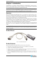
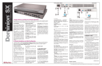
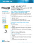
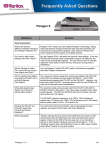
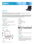
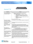
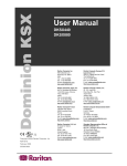
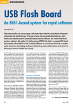
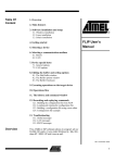
Paragon and Dominion KX II
Serial Device Computer
Interface Modules
P2CIM-SER/P2CIM-SER-EU
User Guide
Release 2.62
Copyright © 2010 Raritan, Inc.
P2SER-0E-E
July 2010
255-33-7000-00
This page intentionally left blank.
Copyright and Trademark Information
This document contains proprietary information that is protected by copyright. All rights reserved.
No part of this document may be photocopied, reproduced, or translated into another language
without express prior written consent of Raritan, Inc.
© Copyright 2010 Raritan, Paragon, CommandCenter, Dominion, and the Raritan company logo
are trademarks or registered trademarks of Raritan, Inc. All rights reserved. Java is a registered
trademark of Sun Microsystems, Inc. Internet Explorer is a registered trademark of Microsoft
Corporation. Netscape and Netscape Navigator are registered trademarks of Netscape
Communication Corporation. All other marks are the property of their respective owners.
FCC Information
This equipment has been tested and found to comply with the limits for a Class A digital device,
pursuant to Part 15 of the FCC Rules. These limits are designed to provide reasonable protection
against harmful interference in a commercial installation. This equipment generates, uses, and can
radiate radio frequency energy and if not installed and used in accordance with the instructions,
may cause harmful interference to radio communications. Operation of this equipment in a
residential environment may cause harmful interference.
VCCI Information (Japan)
Raritan is not responsible for damage to this product resulting from accident, disaster, misuse,
abuse, non-Raritan modification of the product, or other events outside of Raritan’s reasonable
control or not arising under normal operating conditions.
C
UL
US
1F61
I.T.E.
LI STED
For assistance in the North or South America, please contact the Raritan Technical Support Team
by telephone (732) 764-8886, by fax (732) 764-8887, or by e-mail [email protected]
Ask for Technical Support – Monday through Friday, 8:00 a.m. to 8:00 p.m., Eastern.
For assistance around the world, please see the back cover of this guide for
regional Raritan contact information.
Power Safety Guidelines
To avoid potentially fatal shock hazard and possible damage to Raritan equipment:
• Do not use a 2-wire power cord in any product configuration.
• Test AC outlets at your computer and monitor for proper polarity and grounding.
• Use only with grounded outlets at both the computer and monitor. When using a backup UPS,
power the computer, monitor and appliance off the supply.
Rack Mount Safety Guidelines
In Raritan products which require Rack Mounting, please follow these precautions:
• Operation temperature in a closed rack environment may be greater than room temperature.
Do not exceed the rated maximum ambient temperature of the appliances.
• Ensure sufficient airflow through the rack environment.
• Mount equipment in the rack carefully to avoid uneven mechanical loading.
• Connect equipment to the supply circuit carefully to avoid overloading circuits.
• Ground all equipment properly, especially supply connections, such as power strips (other
than direct connections), to the branch circuit.
CONTENTS
i
Contents
Chapter 1: Introduction ....................................................................................................1
Overview....................................................................................................................................1
Product Photos ...........................................................................................................................1
Product Features ........................................................................................................................1
Language Keyboards .................................................................................................................3
Package Contents .......................................................................................................................3
Chapter 2: Installation ......................................................................................................4
Before You Begin ......................................................................................................................4
Connecting the Converter to an ASCII Device..........................................................................4
Connecting the Converter to a Power Source ............................................................................4
Connecting the Converter to a KVM Switch .............................................................................5
Chapter 3: Operation ........................................................................................................6
Working in On-Line Mode ........................................................................................................6
Video Display.....................................................................................................................................6
Display Components..........................................................................................................................6
Functions Keys ..................................................................................................................................7
Configuring the Converter .........................................................................................................7
Setting the Communications Parameters ..........................................................................................7
Programming the Function Keys .......................................................................................................8
Viewing and Editing the Buffer.................................................................................................9
Obtaining On-Line Help ..........................................................................................................10
Appendix A: PWR-SER-4 Power Adapter....................................................................11
Product Photos .........................................................................................................................11
Package Contents .....................................................................................................................11
Product Installation ..................................................................................................................11
Appendix B: Field Firmware Upgrade ..........................................................................12
Perform the upgrade.................................................................................................................12
Appendix C: Pin Definition of DB9 Connector.............................................................13
ii
Paragon and Dominion KX II Serial Device CIM User Guide
Figures
Figure 1
Figure 2
Figure 3
Figure 4
Figure 5
Figure 6
Figure 7
Figure 8
P2CIM-SER/P2CIM-SER-EU........................................................................................................ 1
P2CIM-SER/P2CIM-SER-EU Connectors .................................................................................... 4
Video Display ................................................................................................................................ 6
Setup Screen ................................................................................................................................ 8
Set Up Programmable Keys Screen ............................................................................................. 8
Buffer Edit Screen......................................................................................................................... 9
Help Screen ................................................................................................................................ 10
PWR-SER-4 Components .......................................................................................................... 11
CHAPTER 1: INTRODUCTION
1
Chapter 1: Introduction
Congratulations on purchasing a Raritan P2CIM-SER or P2CIM-SER-EU terminal converter.
This User Guide explains how to use these converters to access and operate an ASCII serial
device through a Raritan Dominion KX II or Paragon KVM switch.
Note: The P2CIM-SER and P2CIM-SER-EU are functionally identical. The only difference
between the two is that the P2CIM-SER-EU supports a wider variety of non-English language
keyboards and character sets. Refer to “Language Keyboards” below for details.
Overview
Both the P2CIM-SER and P2CIM-SER-EU allow you to administer an ASCII serial device that is
connected to a Dominion KX II, Paragon II or MasterConsole CAT (MCCAT) KVM switch.
They do this by emulating an ASCII terminal and converting the serial data from the ASCII
device into PS/2 keyboard and VGA video (800x600x60) signals.
Installing either converter is quite easy. All you have to do is connect the converter to a serial port
on an ASCII device using its serial DB9 connector, and then to a KVM switch using a standard
Category 5e UTP cable. You also have to connect its USB connector to a powered USB port, or
to a separately available Raritan PWR-SER-4 power adapter, to obtain power.
One this is done, you can use the KVM switch’s monitor and keyboard to access and operate the
ASCII device. You can now administer the device through a Paragon II or Dominion KX II
switch.
Note: The PWR-SER-4 power adapter allows you to connect up to four devices to a standard
power outlet by means of a USB connector. It must be ordered separately from Raritan. Refer to
Appendix A for details.
Product Photos
Figure 1 P2CIM-SER/P2CIM-SER-EU
Product Features
Both the P2CIM-SER and P2CIM-SER-EU provide the features listed below:
• Interoperates with an ASCII device as if the device were attached to a text terminal.
• Generates video 800x600x60 with PS/2 keyboard
• Includes an 8-page circular buffer containing the last 8 pages of data from the ASCII device.
Administrators can view, copy and edit the data in the buffer.
• Provides 12 programmable function keys for ease of use. Administrators can program the
keys to send frequently-used character strings or commands to an ASCII device with one
keystroke.
2
Paragon and Dominion KX II Serial Device CIM User Guide
•
Works with Raritan Paragon II, Dominion KX II, and MCCAT KVM switches for convenient
access to multiple ASCII devices and LAN/WAN components.
CHAPTER 1: INTRODUCTION
3
Language Keyboards
The P2CIM-SER supports ISO-646 with these language keyboards:
• USA
• French
• German
• UK
• Denmark I
• Swedish
• Italian
• Spanish I
• Japanese English
• Norway
• Denmark II
• Spanish II
• Latino America
• Korean English
• Legal
The P2CIM-SER-EU is the same as the P2CIM-SER except it supports ISO 8859-1 with these
language keyboards:
• Danish
• Dutch
• English (USA)
• English (U.K.)
• Finnish (same as Sweden)
• French (Belgian)
• French (Canadian)
• French (France)
• French (Swiss)
• German (Germany)
• German (Swiss)
• Italian
• Norwegian
• Portuguese
• Portuguese (Brasil)
• Spanish (Spain)
• Spanish (America)
• Swedish
The P2CIM-SER-EU can also display the different language characters that are specified by
ISO8859-1.
Package Contents
(1) P2CIM-SER or P2CIM-SER-EU
4
Paragon and Dominion KX II Serial Device CIM User Guide
Chapter 2: Installation
This chapter explains how to install a P2CIM-SER or P2CIM-SER-EU terminal converter. This
entails connecting the converter to an ASCII device, a power source, and a KVM switch.
Before You Begin
Before beginning the installation, connect the P2CIM-SER/P2CIM-SER-EU’s USB connector to
a powered USB port, or connect it to a PWR-SER-4 to obtain power.
Make sure the serial port on the ASCII device you will be connecting to the converter is properly
configured. The port should be set to the following parameters:
• Baud rate = 9600 bps
• Parity = None
• Data bits = 8
• Stop bits = 1
Note: The maximum baud rate permitted is 19200 bps.
Connecting the Converter to an ASCII Device
To connect the converter to an ASCII device:
1. Remove the P2CIM-SER or P2CIM-SER-EU from the box in which it was shipped.
2. Take the DB9 connector on the P2CIM-SER or P2CIM-SER-EU and attach it directly to a
serial port on the ASCII device.
Figure 2 P2CIM-SER/P2CIM-SER-EU Connectors
Note: If the ASCII device consists of an RJ45 connection for console management, you may
connect the P2CIM-SER or P2CIM-SER-EU by utilizing the following Raritan components:
¾ RJ45 (female) to DB9 (male) serial adapter -- part number: ASCSDB9M
¾ 1 serial rollover Category 5 adapter cable, RJ45 (male) to RJ45 (female) -- part number:
CRLVR-1
Connecting the Converter to a Power Source
A P2CIM-SER or P2CIM-SER-EU must be connected to a power source by means of its USB
connector. You can insert the USB connector into a USB port on the ASCII device, another
device, or a Raritan PWR-SER-4 power adapter.
The PWR-SER-4 must be ordered separately. If you are using one, refer to Appendix A for
installation instructions.
CHAPTER 2: INSTALLATION
5
Connecting the Converter to a KVM Switch
To connect the converter to a Raritan Dominion KX II or Paragon KVM switch:
1. Take a standard Category 5e UTP cable and connect one end to the RJ45 connector on the
P2CIM-SER or P2CIM-SER-EU.
2. Connect the other end of the cable to a channel port on the KVM switch.
Installation is now complete. You can now access and operate the ASCII device using the
switch’s monitor and keyboard.
Note: The maximum cable length of the converter varies depending on the type of the KVM switch
being connected. See the user guide of the specific KVM switch for the cable length limitation.
These user guides are available on Raritan’s Product Documentatin web page:
http://www.raritan.com/support/productdocumentation.
6
Paragon and Dominion KX II Serial Device CIM User Guide
Chapter 3: Operation
This chapter explains how to administer an ASCII device connected to a Raritan Dominion KX II
or Paragon KVM switch by means of a P2CIM-SER or P2CIM-SER-EU terminal converter. All
the operations described in this chapter can be performed on the switch’s monitor and keyboard.
Working in On-Line Mode
Once you access the ASCII device, you are in On-Line Mode. When the system is in On-Line
Mode, it operates much like a standard ASCII terminal. It allows you to access and control the
ASCII device, and it displays the interaction with the device on your monitor.
Video Display
The video display is an eight color, 800x600 resolution screen consisting of 32 lines of text (80
characters per line). A typical ASCII terminal uses 24 lines, so the P2CIM-SER or P2CIM-SEREU uses the eight extra lines to provide system status and help information. These eight lines are
located on the top four and the bottom four lines of the screen.
Figure 3 Video Display
Display Components
The following describes the components of the eight lines at the top and bottom of the display:
Firmware version
Cursor position and buffer page number
Terminal type and baud rate
Communications status. The status can be one of the following:
• On Line Communicating with an ASCII device. The terminal screen area displays the
interactions with the ASCII device.
• Help Help screen displayed (Pressing Alt+F1 displays the Help screen.)
• Set Up Setup screen displayed. (Pressing Alt+F2 or Alt+F3 enters set-up mode.)
• Buffer Edit Buffer displayed. (Pressing Alt+F4 enters buffer review/edit mode.)
CHAPTER 3: OPERATION
7
Access indicator. It indicates one of the following:
• RMT Remote port (RJ45) is active.
• NO No port is active.
Command keys that can be used with the screen currently displayed
Functions Keys
When in On-Line Mode, you can use any of the functions keys shown below:
PRESS
TO…
Reset the serial communication with the ASCII device and reset the P2CIMCtrl+Break
SER or P2CIM-SER-EU.
Note: This function may only work with Sun workstations.
Ctrl+S
Ctrl+Q
Alt+F1
Alt-F2
Alt+F3
Alt+F4
Stop the ASCII device from sending data. All output data will be queued in
the device.
Order the ASCII device to resume sending data.
Display the Help screen.
Set the serial communications parameters.
Program the programmable function keys.
View and edit the buffer.
Configuring the Converter
You can reset the serial communications parameters on a P2CIM-SER or P2CIM-SER-EU.
The system also provides 12 programmable functions keys that allow you to store frequently-used
character strings or commands. By pressing these keys, you can send the data or commands
directly to an ASCII device with one keystroke. This is ideal for frequently repeated commands.
Setting the Communications Parameters
To set the serial communications parameters on a P2CIM-SER or P2CIM-SER-EU:
1. Press Alt+F2. The Setup Screen appears.
2. You can reset the baud rate, parity, data bits, stop bits or terminal type. To do this:
A. Use the Tab and Shift+Tab keys to move the cursor to a parameter you want to change.
B. Use the ↑ and ↓ keys to scroll through the available parameter settings until you come to
the one you want.
C. Repeat Steps A and B until all necessary parameters have been reset.
3. When you are finished, press ESC to return to On-Line Mode.
8
Paragon and Dominion KX II Serial Device CIM User Guide
Figure 4 Setup Screen
Programming the Function Keys
To program the function keys:
1. Press Alt+F3. The Setup Programmable Keys screen appears. This screen contains entries
for each of the 12 programmable function keys.
Figure 5 Set Up Programmable Keys Screen
CHAPTER 3: OPERATION
9
2. Use the Tab and Shift+Tab keys to move the cursor to a function key.
3. Type a maximum of 16 characters for the function key. To type special characters, use
Ctrl+V. For example, to enter a carriage return (CR), type Ctrl+V + Enter.
4. Repeat Steps 2 and 3 until you have programmed all necessary keys.
5. Press F11/F12 to load and save the programmable keys.
6. Press Esc to return to On-Line Mode.
Viewing and Editing the Buffer
The P2CIM-SER or P2CIM-SER-EU stores the most recent eight pages of data from an ASCII
device in a circular buffer. This enables you to access and operate the device, and also review the
historical data stream on demand. The buffer is a circular eight-page buffer, which means it
retains the most recent eight pages of the data from the device.
To view and edit the data in the buffer:
1. Press Alt+F4. The P2CIM-SER or P2CIM-SER-EU switches from On-Line Mode to Buffer
Edit Mode and displays the Buffer Edit screen.
Figure 6 Buffer Edit Screen
2. Use the Page Up, Page Down, Home, End, ↑ and ↓ keys to view the contents of the buffer
and position the cursor in the Buffer Edit screen.
10
Paragon and Dominion KX II Serial Device CIM User Guide
Obtaining On-Line Help
You can obtain on-line help at any time during your session by pressing Alt+F1. This displays
the Help screen, which lists the on-line, setup, and buffer edit commands.
Figure 7 Help Screen
APPENDIX A: PWR-SER-4 POWER ADAPTER
11
Appendix A: PWR-SER-4 Power Adapter
The PWR-SER-4 power adapter enables you to connect up to four P2CIM-SER or P2CIM-SEREUs to a standard power outlet using their USB connectors.
Product Photos
Figure 8 PWR-SER-4 Components
Package Contents
(1) PWR-SER-4 power adapter
(1) Expansion unit
(1) Mounting bracket
Product Installation
To connect one P2CIM-SER or P2CIM-SER-EU to the PWR-SER-4:
1. Insert a USB connector on the device into the USB port on the PWR-SER-4
2. Plug the PWR-SER-4 into a power outlet.
To connect up to four P2CIM-SER or P2CIM-SER-EUs to the PWR-SER-4:
1. Insert the USB connector on the expansion unit into the USB port on the PWR-SER-4.
2. Insert up to four USB connectors from the P2CIM-SER or P2CIM-SER-EU into the USB
ports on the expansion unit.
3. Plug the PWR-SER-4 into a power outlet.
The PWR-SER-4 also comes with a bracket to mount the device on a rack.
12
Paragon and Dominion KX II Serial Device CIM User Guide
Appendix B: Field Firmware Upgrade
This appendix explains how to perform a field firmware upgrade.
Perform the upgrade
1. This upgrade requires the use of Atmel’s FLIP (Flexible In-system Programmer). Open a
browser and point it at the Atmel Corporation website:
http://www.atmel.com
Once there, obtain a copy of their FLIP tool and install it on a PC.
2. Download the latest P2CIM-SER firmware release (xxx.hex) from Raritan’s support website
(http://www.raritan.com/support/firmwareupgrades/paragonII).
3. Set the slide switch on the P2CIM-SER/P2CIM-SER-EU to “P” status. The switch can be
found to the right of the Raritan label on the underside of the device.
4. Connect the P2CIM-SER/P2CIM-SER-EU’s DB9 connector to a serial port on the PC with
the Flip software installed.
5. Connect the P2CIM-SER/P2CIM-SER-EU’s USB connector to a USB port on another device
or to a PWR-SER-4 power adaptor. This powers ON the P2CIM-SER/P2CIM-SER-EU.
6. Launch the Flip software, select AT89C51RD2 chip, and set communication to RS-232:
− Offset = 0000
− BLJB is checked
− BSB = 00
− EB = FF
− SBV = FC
− Device SSB = level 2
− RS-232 communication baud rate = 38400
7. Load the latest firmware for the P2CIM-SER/P2CIM-SER-EU.
8. Click Run to install the firmware on the P2CIM-SER/P2CIM-SER-EU.
9. After the installation is complete, power OFF the P2CIM-SER/P2CIM-SER-EU and
disconnect it from the PC.
10. Set slide switch on P2CIM-SER/P2CIM-SER-EU to “S” status. The firmware upgrade is now
complete.
Appendix C: Pin Definition of DB9 Connector
The female DB9 connector of the P2CIM-SER or P2CIM-SER-EU is a standard Data
Communication Equipment (DCE) serial connector. The following table lists the signal of each
pin. Please note that P2CIM-SER and P2CIM-SER-EU do NOT support RS-232 hardware flow
control.
PIN NUMBER
1
2
3
4
5
6
7
8
9
255-33-7000
SIGNAL
None
TxD
RxD
DSR
Ground
DTR
CTS
RTS
None
¾
U.S./Canada/Latin America
Monday ‐ Friday 8 a.m. ‐ 8 p.m. ET Phone: 800‐724‐8090 or 732‐764‐8886 For CommandCenter NOC: Press 6, then Press 1 For CommandCenter Secure Gateway: Press 6, then Press 2 Fax: 732‐764‐8887 Email for CommandCenter NOC: tech‐[email protected] Email for all other products: [email protected] ¾
China
Beijing
Monday ‐ Friday 9 a.m. ‐ 6 p.m. local time Phone: +86‐10‐88091890 Shanghai
Monday ‐ Friday 9 a.m. ‐ 6 p.m. local time Phone: +86‐21‐5425‐2499 Europe
Europe
Monday ‐ Friday 8:30 a.m. ‐ 5 p.m. GMT+1 CET Phone: +31‐10‐2844040 Email: [email protected] United Kingdom
Monday ‐ Friday 8:30 a.m. to 5 p.m. GMT+1 CET Phone +44‐20‐7614‐77‐00 France Monday ‐ Friday 8:30 a.m. ‐ 5 p.m. GMT+1 CET Phone: +33‐1‐47‐56‐20‐39 Germany
Monday ‐ Friday 8:30 a.m. ‐ 5 p.m. GMT+1 CET Phone: +49‐20‐17‐47‐98‐0 Korea
GuangZhou
¾
Monday ‐ Friday 9 a.m. ‐ 6 p.m. local time Phone: +86‐20‐8755‐5561 Monday ‐ Friday 9 a.m. ‐ 6 p.m. local time Phone: +82‐2‐5578730 ¾
India
Monday ‐ Friday 9 a.m. ‐ 6 p.m. local time Phone: +91‐124‐410‐7881 ¾
Japan
Monday ‐ Friday 9:30 a.m. ‐ 5:30 p.m. local time Phone: +81‐3‐3523‐5994 Email: [email protected] ¾
¾
Melbourne, Australia
Monday ‐ Friday 9:00 a.m. ‐ 6 p.m. local time Phone: +61‐3‐9866‐6887 ¾
Taiwan
Monday ‐ Friday 9 a.m. ‐ 6 p.m. GMT ‐5 Standard ‐4 Daylight Phone: +886‐2‐8919‐1333 Email: [email protected]