1
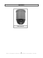
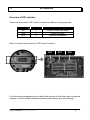
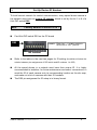
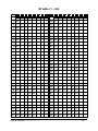
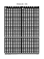
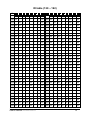
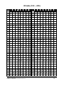
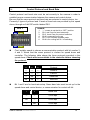
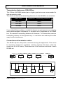
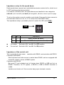
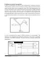
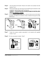
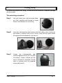
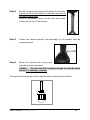
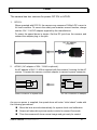
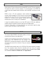
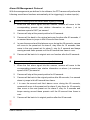
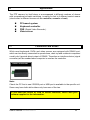
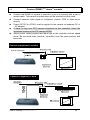
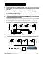
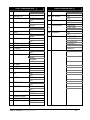
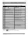
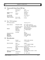
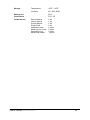
USER’S MANUAL PTZ Dome Camera V 1.3 Please read this manual carefully before using, and save this manual for future reference .. Vidia Srl – Via Vasanello 23, 00189 Roma – Tel. 06.30316333 – Fax 06.30350231 - www.vidia.it CONTENTS Safety Information Preface Feature List Product Appearance Basic Setup 1 2 3 4 5 5.1 5.2 5.3 5.4 5.5 Access the DIP switches DIP switches Device ID Control Protocol and Baud Rate RS485 Network and impedance Mount the Dome camera 6 Mounting accessory Surface mount 6.3 Embedded 6.4 Wall -mounting 6.5 Ceiling-drop 6.1 6.2 Connecting wires 7 Power Video 7.3 RS485 7.4 Alarm I/O 7.1 7.2 Applications 8 8.1 Controllers and RS485 8.2 8.3 Connect a single dome Connect two or more domes Camera setup – OSD functions 9 9.1 OSD operation 9.2 Function list and description 9.3 OSD function setup example 10 11 12 Pre-defined system functions Advanced Setting -Preset function Specification ………………….. ………………….. ………………….. ………………….. ………………….. ………………….. ………………….. ………………….. ………………….. ………………….. ………………….. ………………….. ………………….. ………………….. ………………….. ………………….. ………………….. ………………….. ………………….. ………………….. ………………….. ………………….. ………………….. ………………….. ………………….. ………………….. ………………….. ………………….. ………………….. ………………….. ………………….. ………………….. 3 4 5 6 7 7 8 9 14 15 18 19 20 21 22 24 26 27 28 28 29 32 32 33 36 38 38 38 41 46 47 48 .. Vidia Srl – Via Vasanello 23, 00189 Roma – Tel. 06.30316333 – Fax 06.30350231 - www.vidia.it Safety Information Federal Communication Commission (FCC) Statement NOTE: This equipment has been tested and found to comply with the limits of a Class B digital device, pursuant to Part 15 of the FCC Rules. These limits are designed to provide reasonable protection against harmful interference when the equipment is operated in a commercial environment. This device generates, uses and can radiate radio frequency energy and, if not installed and used in accordance with the instruction manual, may cause harmful interference to radio communications. However, there is no guarantee that interference will not occur in a particular installation. If this equipment does cause harmful interference, the user is encouraged to try to correct the interference by on or more of the following measures: Reorient or relocate the receiving antenna. Increase the separation between the equipment and receiver. Correct the equipment into an output o a circuit different from that to which the receiver is connected Consult the dealer or an experienced radio / television technician for help FCC Caution: To assure continued compliance, any change or modification not expressly approved by the party responsible for compliance could void the user’s authority to operate this equipment. Notice for customers in Canada CAUTION This Class B digital apparatus meets all requirements of the Canadian Interference Causing Equipment Regulations. ATTENTION Cet appareil numerique de laclasse B respects toutes les exigencies du Reglement sur le materiel brouilleur du Canada .. Vidia Srl – Via Vasanello 23, 00189 Roma – Tel. 06.30316333 – Fax 06.30350231 - www.vidia.it Preface Congratulations for the purchasing of the world most compact PTZ (Pan, Tilt and Zoom) camera. The camera is designed and manufactured not just to meet the requirements for traditional CCTV and modern digital surveillance, but also increase the systems’ overall performance. o o The PT mechanism provides controllable panning (360 ) and tilting (90 )+ o auto-rotation (180 ) functions, giving users the capability to manipulate the camera for precise locating on target. The built-in micro-controller allows users to program up to 64 presets for quick and accurate capture to specific view positions. Moving speed, ranging from 0.25 to 300 degrees per second and is selectable to controller, is variable in 16 optional levels. Dwell time of each view position is also selectable from 1second up to 255 seconds. System function includes I/O for alarm function for intrusion management, ID setup (maximum to 255) and impedance matching option for multiple node system, 2 control protocols, 3 options of baud rates, RS485 communication format. This device is driven by DC12V or AC24V power. It can be controlled by keyboard, PC, video server or standalone DVR. Majority of image related functions (such as DSP functions, lens functions, special effects of video…) are managed via OSD (On-Screen-Display) menu. These functions are explained in the section of OSD with details. The CCD can be set up for automatic switching to black-white mode for night-vision ready when illumination is low. This camera is designed to be water-resistant for outdoor use, under the o o condition of normal temperature range from -10 to 50 C. .. Vidia Srl – Via Vasanello 23, 00189 Roma – Tel. 06.30316333 – Fax 06.30350231 - www.vidia.it Features Compact Size of 4-1/2” (114 mm) diameter High resolution color CCD 480 TV lines 23 times optical zoom Continuous panning for 360 ; Tilt for 90 +auto-rotation (180 ) Fast rotation speed, up to 300 per second RS-485 digital control, supporting multi-nude topology BNC connector for video output Programmable for view position, speed and dwell View position preset, up to 64 points Auto-pan and 4 groups of tour 3 alarm inputs and 1 alarm output Compatible with Pelco D and Pelco P protocols Internal ID setup function, maximum to 255 Compatible with keyboard and DVR for CCTV system Compatible with PC and video server for WAN / LAN surveillance 12V DC or 24V AC power input Water resistant design (IP-67 grade) Be able for embedded, surface, wall and ceiling mount o o o o .. Vidia Srl – Via Vasanello 23, 00189 Roma – Tel. 06.30316333 – Fax 06.30350231 - www.vidia.it Appearance Power Zoom 23X .. Vidia Srl – Via Vasanello 23, 00189 Roma – Tel. 06.30316333 – Fax 06.30350231 - www.vidia.it To access DIP switches 5.1 Before the camera is mounted in place, be sure the following four settings are properly executed, or the camera may fail the control: Camera ID setup Protocol selection Baud rate selection Termination impedance Important Notice All the DIP switches for setting up camera ID, protocol, baud rate and RS485 terminating impedance are inside the dome, and accessible via a opening on the bottom. In normal condition, this opening is sealed with a piece of metal cover. The metal cover, together with a robber around the opening, is for stopping water and dust going inside. Therefore, installer must be very careful during the opening or putting back the metal cover. Tools: 1. 2. Philips (or “plus type”) screw driver #2, for opening and putting back the cover Pincer, paper clip or small flat screw driver, to move the lever of DIP switch Access point to DIP switches for setups: To open the cover, take the two screws off from bottom chassis, as the instruction on below: Take the two screws off . User’s manual D06469810013G . 7 DIP switches 5.2 Overview of DIP switches There are three sets of DIP switch on board for different setup purposes. location # DS1 DS2 DS3 bit quantity 8 8 2 used for Protocol / baud rate setup Device ID setup Network impedance Refer to the picture on below for DIP switch locations. DS3 DS1 DS2 In the following paragraphs are the detail descriptions of the three main setups the installer must do, before hardware mounting and cabling work should begin. . User’s manual D06469810013G . 8 Set Up Device ID Number 5.3 To build correct network for control communication, every speed dome camera in the network must have an unique ID number, which is set by the bit 1 to 8 of a 8-bit DIP switch DS2. Note: Factory default of device ID is 1 Find 8-bit DIP switch DS2 on the PC board DS2 remark: Dash line “---“ in table means to set the bit to “OFF” position Bit number Refer to the tables in the next two pages for ID setting (the tables will show the relation between pin assignments of DIP switch and ID numbers 1 to 255) All the speed domes in a network must have their unique ID. It is highly recommended to installers, for future maintenance and users’ convenience, to mark the ID of each camera onto its corresponding location on the site map, and make out a list of cameras with their ID numbers. The DS2 pin assignment for ID setup is in binary format. . User’s manual D06469810013G . 9 ID table (1 ~ 64) ID 1 2 3 4 5 6 7 8 ID 1 2 3 4 5 6 7 8 1 -- -- -- -- -- -- -- -- 33 -- -- -- -- -- on -- 2 on -- -- -- -- -- -- -- 34 on -- -- -- -- on -- --- 3 -- on -- -- -- -- -- -- 35 -- on -- -- -- on -- -- 4 on on -- -- -- -- -- -- 36 on on -- -- -- on -- -- 5 -- -- on -- -- -- -- -- 37 -- -- on -- -- on -- -- 6 on -- on -- -- -- -- -- 38 on -- on -- -- on -- -- 7 -- on on -- -- -- -- -- 39 -- on on -- -- on -- -- 8 on on on -- -- -- -- -- 40 on on on -- -- on -- -- 9 -- -- -- on -- -- -- -- 41 -- -- -- on -- on -- -- 10 on -- -- on -- -- -- -- 42 on -- -- on -- on -- -- 11 -- on -- on -- -- -- -- 43 -- on -- on -- on -- -- 12 on on -- on -- -- -- -- 44 on on -- on -- on -- -- 13 -- -- on on -- -- -- -- 45 -- -- on on -- on -- -- 14 on -- on on -- -- -- -- 46 on -- on on -- on -- -- 15 -- on on on -- -- -- -- 47 -- on on on -- on -- -- 16 on on on on -- -- -- -- 48 on on on on -- on -- -- 17 -- -- -- -- on -- -- -- 49 -- -- -- -- on on -- -- 18 on -- -- -- on -- -- -- 50 on -- -- -- on on -- -- 19 -- on -- -- on -- -- -- 51 -- on -- -- on on -- -- 20 on on -- -- on -- -- -- 52 on on -- -- on on -- -- 21 -- -- on -- on -- -- -- 53 -- -- on -- on on -- -- 22 on -- on -- on -- -- -- 54 on -- on -- on on -- -- 23 -- on on -- on -- -- -- 55 -- on on -- on on -- -- 24 on on on -- on -- -- -- 56 on on on -- on on -- -- 25 -- -- -- on on -- -- -- 57 -- -- -- on on on -- -- 26 on -- -- on on -- -- -- 58 on -- -- on on on -- -- 27 -- on -- on on -- -- -- 59 -- on -- on on on -- -- 28 on on -- on on -- -- -- 60 on on -- on on on -- -- 29 -- -- on on on -- -- -- 61 -- -- on on on on -- -- 30 on -- on on on -- -- -- 62 on -- on on on on -- -- 31 -- on on on on -- -- -- 63 -- on on on on on -- -- 32 on on on on on -- -- -- 64 on on on on on on -- -- . User’s manual D06469810013G . 10 ID table (65 ~ 128) ID 1 2 3 4 5 6 7 8 ID 1 2 3 4 5 6 7 8 65 -- -- -- -- -- -- on -- 97 -- -- -- -- -- on on -- 66 on -- -- -- -- -- on -- 98 on -- -- -- -- on on -- 67 -- on -- -- -- -- on -- 99 -- on -- -- -- on on -- 68 on on -- -- -- -- on -- 100 on on -- -- -- on on -- 69 -- -- on -- -- -- on -- 101 -- on -- -- on on -- 70 on -- on -- -- -- on -- 102 on -- on -- -- on on -- 71 -- on on -- -- -- on -- 103 -- on on -- -- on on -- 72 on on on -- -- -- on -- 104 on on on -- -- on on -- 73 -- -- -- on -- -- on -- 105 -- -- -- on -- on on -- 74 on -- -- on -- -- on -- 106 on -- -- on -- on on -- 75 -- on -- on -- -- on -- 107 -- on -- on -- on on -- 76 on on -- on -- -- on -- 108 on on -- on -- on on -- 77 -- -- on on -- -- on -- 109 -- -- on on -- on on -- 78 on -- on on -- -- on -- 110 on -- on on -- on on -- 79 -- on on on -- -- on -- 111 -- on on on -- on on -- 80 on on on on -- -- on -- 112 on on on on -- on on -- 81 -- -- -- -- on -- on -- 113 -- -- -- -- on on on -- 82 on -- -- -- on -- on -- 114 on -- -- -- on on on -- 83 -- on -- -- on -- on -- 115 -- on -- -- on on on -- 84 on on -- -- on -- on -- 116 on on -- -- on on on -- 85 -- -- on -- on -- on -- 117 -- on -- on on on -- 86 on -- on -- on -- on -- 118 on -- on -- on on on -- 87 -- on on -- on -- on -- 119 -- on on -- on on on -- 88 on on on -- on -- on -- 120 on on on -- on on on -- 89 -- -- -- on on -- on -- 121 -- -- on on on on -- 90 on -- -- on on -- on -- 122 on -- -- on on on on -- 91 -- on -- on on -- on -- 123 -- on -- on on on on -- 92 on on -- on on -- on -- 124 on on -- on on on on -- 93 -- -- on on on -- on -- 125 -- -- on on on on on -- 94 on -- on on on -- on -- 126 on -- on on on on on -- 95 -- on on on on -- on -- 127 -- on on on on on on -- 96 on on on on on -- on -- 128 on on on on on on on -- . User’s manual D06469810013G -- -- -- . 11 ID table (129 ~ 192) ID 1 2 3 4 5 6 7 8 ID 1 2 3 4 5 6 7 8 129 -- -- -- -- -- -- -- on 161 -- -- -- -- -- on -- on 130 on -- -- -- -- -- -- on 162 on -- -- -- -- on -- on 131 -- on -- -- -- -- -- on 163 -- on -- -- -- on -- on 132 on on -- -- -- -- -- on 164 on on -- -- -- on -- on 133 -- on -- -- -- -- on 165 -- on -- -- on -- on -- -- 134 on -- on -- -- -- -- on 166 on -- on -- -- on -- on 135 -- on on -- -- -- -- on 167 -- on on -- -- on -- on 136 on on on -- -- -- -- on 168 on on on -- -- on -- on 137 -- -- -- on -- -- -- on 169 -- -- -- on -- on -- on 138 on -- -- on -- -- -- on 170 on -- -- on -- on -- on -- on -- on -- -- -- on 171 -- on -- on -- on -- on 140 on on -- on -- -- -- on 172 on on -- on -- on -- on 139 141 -- -- on on -- -- -- on 173 -- -- on on -- on -- on 142 on -- on on -- -- -- on 174 on -- on on -- on -- on -- on on on -- -- -- on 175 -- on on on -- on -- on 144 on on on on -- -- -- on 176 on on on on -- on -- on 143 145 -- -- -- -- on -- -- on 177 -- -- -- -- on on -- on 146 on -- -- -- on -- -- on 178 on -- -- -- on on -- on 147 -- on -- -- on -- -- on 179 -- on -- -- on on -- on 148 on on -- -- on -- -- on 180 on on -- -- on on -- on 149 -- on -- on -- -- on 181 -- on -- on on -- on -- -- 150 on -- on -- on -- -- on 182 on -- on -- on on -- on 151 -- on on -- on -- -- on 183 -- on on -- on on -- on 152 on on on -- on -- -- on 184 on on on -- on on -- on 153 -- -- on on -- -- on 185 -- -- on on on -- on -- -- 154 on -- -- on on -- -- on 186 on -- -- on on on -- on 155 -- on -- on on -- -- on 187 -- on -- on on on -- on 156 on on -- on on -- -- on 188 on on -- on on on -- on 157 -- -- on on on -- -- on 189 -- -- on on on on -- on 158 on -- on on on -- -- on 190 on -- on on on on -- on -- on on on on -- -- on 191 -- on on on on on -- on 160 on on on on on -- -- on 192 on on on on on on -- on 159 . User’s manual D06469810013G . 12 ID table (193 ~ 255) ID 1 2 3 4 5 6 7 8 ID 1 2 3 4 5 6 7 8 193 -- -- -- -- -- -- on on 225 -- -- -- -- -- on on on 194 on -- -- -- -- -- on on 226 on -- -- -- -- on on on 195 -- on -- -- -- -- on on 227 -- on -- -- -- on on on 196 on on -- -- -- -- on on 228 on on -- -- -- on on on 197 -- on -- -- -- on on 229 -- on -- -- on on on -- -- 198 on -- on -- -- -- on on 230 on -- on -- -- on on on 199 -- on on -- -- -- on on 231 -- on on -- -- on on on 200 on on on -- -- -- on on 232 on on on -- -- on on on 201 -- -- -- on -- -- on on 233 -- -- -- on -- on on on 202 on -- -- on -- -- on on 234 on -- -- on -- on on on -- on -- on -- -- on on 235 -- on -- on -- on on on 204 on on -- on -- -- on on 236 on on -- on -- on on on 203 205 -- -- on on -- -- on on 237 -- -- on on -- on on on 206 on -- on on -- -- on on 238 on -- on on -- on on on -- on on on -- -- on on 239 -- on on on -- on on on 208 on on on on -- -- on on 240 on on on on -- on on on 207 209 -- -- -- -- on -- on on 241 -- -- -- -- on on on on 210 on -- -- -- on -- on on 242 on -- -- -- on on on on 211 -- on -- -- on -- on on 243 -- on -- -- on on on on 212 on on -- -- on -- on on 244 on on -- -- on on on on 213 -- on -- on -- on on 245 -- on -- on on on on -- -- 214 on -- on -- on -- on on 246 on -- on -- on on on on 215 -- on on -- on -- on on 247 -- on on -- on on on on 216 on on on -- on -- on on 248 on on on -- on on on on 217 -- -- on on -- on on 249 -- -- on on on on on -- -- 218 on -- -- on on -- on on 250 on -- -- on on on on on 219 -- on -- on on -- on on 251 -- on -- on on on on on 220 on on -- on on -- on on 252 on on -- on on on on on 221 -- -- on on on -- on on 253 -- -- on on on on on on 222 on -- on on on -- on on 254 on -- on on on on on on -- on on on on -- on on 255 on on on on on on on 224 on on on on on -- on on 223 . User’s manual D06469810013G -- . 13 Control Protocol and Baud Rate 5.4 Control protocol and baud rate must be set correctly to the camera in order to establish proper communication between the camera and control device. Be sure that the same protocol and baud rate are selected in control device, too. Presently 2 types of protocol and 3 levels of baud rate are provided by this speed dome, through an 8-bit DIP switch labeled DS1. DS 1 remark: 1. 2. 3. 4. 5. 6. “--“ means to set the bit to “OFF” position Bit 1 and 2 are for baud rate setup Bit 3, 4 and 5 are for protocol selection Bit 6 is reserved future use Bit 7 is for firmware upgrade mode Bit 8 is for cooling fan on / off switching First, installer needs to choose a communication protocol with bit number 3, 4 and 5. Watch that the same protocol is chosen for speed dome and controller. The following table shows the three protocols provided in this speed dome. Check what are available in the controller before choosing the protocol. 3 4 5 Protocol -on --- --- Pelco-D -- on -- Reserved on on -- Reserved Pelco-P Bit 1 and 2 are for baud rate setup. Same baud rate must be set up for the speed dome and control device, or communication for control will fail. 1 2 Baud rate -- -- 2,400 bps on -- 4,800 bps -- on 9,600 bps . User’s manual D06469810013G . 14 RS485 Network and Impedance 5.5 Transmission distances of RS485 Bus The 0.56mm (AWG#24) twisted pair or higher grade wires are recommended for data transmission cable The maximum theoretical transmitting distances, for the AWG#24, are as follows: Baud Rate Maximum Transmitting Distance 2400 Bps 1800m 4800 Bps 1200m 9600Bps 800m If user selects thinner cables, or installs the dome in an environment surrounded by strong electromagnetic interference, or connects lots of equipment to the RS485 bus, the maximum transmitting distance will decrease. To increase the maximum transmitting distance, do the opposite way, i.e. use thicker wire and keep the cable away from the interference. Connection and terminator resistor The RS485 requires daisy-chain connection among the equipments. There must be terminator resistors for impedance matching (typically 120 ohms, within the range from 90 to 250 ohms). Terminators are to be located at both ends of each RS-485 net. ..... 120O 1# 2# 3# 4# 120O 32# A+ . . . . . BD A+ B. . . . . 120£ [ 1# 2 . User’s manual D06469810013G 3 120£ [ 32 . 15 Impedance setup for the speed dome Each speed dome camera has a switchable terminator resistor built in, which is set to OFF position as the factory default. In a network of RS485 chain, the speed domes are classified in two categories: end unit (unit #1 and #32) and node (#2 through #31). refer to chart in previous page. To set up the resistor correctly, installer must decide if the specific dome camera is the termination device or not, i.e. if it is at the end of the RS485 chain. The impedance setup is provided by the bit 1 and bit 2 of DIP switch DS3 . DS3 Bit 1 Bit 2 Impedance -- -- Open ( device on node ) On On Standard 120 ohms ( device at end ) For nodes: Set both of Bit 1 and Bit 2 to OFF position For end unit: Set both of Bit 1 and Bit 2 to ON position Impedance of the control unit This is generally for two cases: controller with RS485, and controller with RS232. Controller with RS485: Most keyboard and video server in market have RS485, and are equipped with terminator resistor to drive a RS485 system. Controller with RS-232 But most PC and notebook sort of devices have RS232 or USB port but no RS485. Therefore, for PC system, a RS232 or USB to RS485 converter is neded. Installer must check out if the converter has proper terminator resistor. . User’s manual D06469810013G . 16 Problems in practical connection In some circumstances user adopts a star configuration in practical connection. The terminator resistors must be connected to the two equipment that are farthest away from each other, such as equipment 1# and 15# in the following picture. As the star configuration is not in conformity with the requirements of RS485 standards, problems such as signal reflections, lower anti-interference performance arise when the cables are long in the connection. The reliability of control signals could be downgraded with the phenomena that your dome camera does not respond to or just responds at intervals to the controller, or does continuous operation without stop In such circumstances the usage of RS485 distributor is recommended. The distributor can change the star configuration connection to the mode of connection stipulated in the RS485 standards. The new connection achieves reliable data transmission. RS485 distributor . User’s manual D06469810013G . 17 6. Mount The Dome Camera There are 4 (four) ways to mount the PTZ camera, which are: 1. 2. 3. 4. Embedded into ceiling Attached to the ceiling surface directly Held to ceiling surface through a bracket Mounted to wall through a bracket Please read the accessory list on the next page to get understand of what components are for which type of mountings. . User’s manual D06469810013G . 18 Mounting Accessory 6.1 The following items are supplied with the speed dome for the camera mounting. Description 1 Plastic ring Photo Use To hold the camera embedded on ceiling Must be used with the metal ring together to hold the PTZ camera.. 2 Metal ring To hold the camera embedded on ceiling Must be used with the plastic decoration ring together to hold the PTZ camera. 3 Mounting base a b 4 5 Metal bowl holder Screw pack . User’s manual D06469810013G To hold the camera on ceiling surface Used together with item # 4 (bowl type holder) for ceiling hold or wall mount To work with item 3 for creating ceiling or wall mount Screws for the build of camera’s holding structure . 19 Surface mount onto Ceiling 6.2 1. 2. 3. 4. Locate the base onto the place the camera is to mount, and fix the base on the place tightly with screws through the 3 holes on the base (be sure screws are complete in the ceiling) Get the camera and secure it to the base with the supplied metal chain. Then fit the camera body to the base, rotate the camera body clockwise until it is completely locked into position. Put the screw A (anti-loss) in position and screw it in In case of dealing with a concrete wall: a. b. Mark the locations for screw through the holes on the base Make holes on the wall, then insert the supplied plastic plugs into the holes and squeeze them in until they are flush with the wall surface. c. Mount the base on the desired place tightly with screws . User’s manual D06469810013G . 20 6.3 Step 1 Embed The Camera Into Ceiling make holes To insert the speed dome into the ceiling, first a hole must be properly made to let the dome be through for hanging. The best way to decide the diameter of the hole, and the spots for mounting screws, is to use the supplied metal holder. Step 2 Put the holder on the surface of the target location and mark a circle with pencil or color marker Also mark out the spots for screws with the screw holes on the holder Cut the camera hole alone with the curve Drill holes for screw in 6 mm (1/4”) on the three marked spots; Integrate the decoration ring with camera The decoration ring is not just for nice looking, but also the piece to hold the camera in place for embedded mounting. To integrate the ring to camera: 1. Take the transparent dome cover off 2. Locate the ring to the bottom side of the cover 3. Put the cover back to the camera Step 3 Mount the camera through the hole Take the below steps to make the camera cling to ceiling: 1. Place the auxiliary metal bracket onto the top of the ceiling 2. Put the camera through out the hole 3. Align the screw holes of the decoration ring and the auxiliary bracket 4. Put screws through and tighten the two brackets, with the ceiling in between . User’s manual D06469810013G . 21 Wall-mounting 6.4 To mount the camera from ceiling, a metal wall-mount bracket in separate package will be needed. The mounting procedure Step 1 Get the metal bowl and mounting base, put them together with screws to make them a sub-assembly for mounting. Step 2 Hook the sub-assembly and camera with the safety cable located on the bottom of camera (left picture on below), then put the signal cables throughout the sub-assembly (right picture). Step 3 Fasten the sub-assembly and camera together at the joint of D-sub connectors. Rotate camera all the way in direction of clockwise. Fix the base to camera with the supplied screw and wrench. . User’s manual D06469810013G . 22 Step 4 Get the wall-mount bracket. Remove the metal cover (sheet) from the bracket Fig-1 Step 5 Mount the bracket onto wall (Fig-2) but DO NOT tight the bracket to wall completely until the Step 6 and 7 are finished. Caution: Be sure the wall is strong enough to hold the entire device (i.e. housing + camera) Step 6 Lay all the signal cables (RS485, video, power and alarm-wires) in the trench of bracket, and have all connectors come out bracket through the cable outlet (Fig-3). Fig-1 Step 7 Fig-2 Fig-3 Fasten the camera module (assembly) to the bracket with supplied screws Fig-4 Step 8 Put the cover back to holder Fig-5 Fig-4 . User’s manual D06469810013G Fig-5 . 23 Ceiling -drop 6.5 To mount the camera from ceiling, a metal wall-mount bracket in separate package will be needed. The mounting procedure Step 1 Get the metal bowl and mounting base, put them together with screws to make them a sub-assembly for mounting. Step 2 Hook the sub-assembly and camera with the safety cable located on the bottom of camera (left picture on below), then put the signal cables throughout the sub-assembly (right picture). Step 3 Fasten the sub-assembly and camera together at the joint of D-sub connectors. Rotate camera all the way in direction of clockwise. Fix the base to camera with the supplied screw and wrench. . User’s manual D06469810013G . 24 Step 4 Get the ceiling mount bracket. Put cables into the tube, starting with the 9-pin alarm I/O (take the male part off to obtain smaller size). Have all connectors come out the tube from cable outlet near the top of the bracket. Step 5 Fasten the camera module (sub-assembly) to the bracket with the supplied screws Step 6 Mount the bracket onto ceiling and tight the bracket completely. Caution: Be sure the wall is strong enough to hold the entire device (i.e. housing + camera) The figure on below shows how it looks like when ceiling-drop is finished . User’s manual D06469810013G . 25 7. Connecting Wires The cables, wires and connector attached to the speed dome are categories into 4 major functions of: 1. 2. 3. 4. Power Video RS485 Alarm-in and out They are easily distinguished from one to another, as being featured with different connectors. Refer to the picture on below to learn about cable and connector information. . User’s manual D06469810013G . 26 Power 7.1 The camera has two versions for power: DC12V or AC24V. 1. DC12V: When operated with DC12V, the camera may consume 1000mA DC current in full load condition. To secure the safety and maintain correct function, always use the 12V / 1.5A DC adapter supplied by the manufacturer. To power the speed dome is simple. Get the DC jack from the camera, and connect the adapter plug to the jack. DC 12V adapter (supplied) 2. AC24V: (AC adapter of 24V / 1.66A is optional.) An AC adapter of 24V / 1.66A is supplied with the camera / housing for the AC version. To power the camera, connect adapter to camera’s power connector. Power Connector on Speed Dome AC 24V Connector on Adaptor As soon as power is supplied, the speed dome will enter “initial check” mode with the following procedures: Move the lens around automatically for system check and calibration Screen will show blue picture words in white for around 5 seconds Then the camera will show normal image and get ready for control . User’s manual D06469810013G . 27 7.2 Video Video output of 1Vp-p is delivered at the female BNC end with 75 ohms impedance. To transmit the video to receiver properly, it is recommended to use RG59 A/U coaxial cable with stranded center conductor, with male BNC connectors on both ends. RG59 is also in 75 ohm impedance, which matches the camera’s output impedance. The A/U version is recommended, rather than the version B/U, due of its superior performance on flexibility for resisting severe twisting, bending and other stresses which occur in many CCTV installations. In case the installation distance is over than 500 meters (1,500 feet), additional amplifier might be needed to keep the video level and image quality. If superior video quality is strongly demanded, you may need to add the video buffer for each 300 meters or even 250 meters. 7.3 RS485 The camera adapts RS485 in half-duplex pattern, a two-pin connectivity as shown on the right picture. Installer must pay attention to the polarity of these two pins – yellow wire is the POSITIVE end, and orange is the NEGATIVE. Communication between controller and camera will break and control will not function if they are reversely connected. yellow + -orange The RS485 communication may run for 4,000 feet if the system network is properly built. Two important factors should be handled with care during the system build-up--- baud rate and termination impedance. More information about RS485 are in sections “Protocol and Baud rate” and “Applications”. . User’s manual D06469810013G . 28 & Alarm Input Alarm Output 7.4 This camera is equipped with 3 alarm-in and one alarm-out for intrusion management. Installers may connect the inputs to various sensors and program the camera to move to specific spots for visual check when evens take place. Dwell time is programmable, subject to the controller (some controllers don’t offer the access to dwell setting) Refer to the table on below for function assignments to each alarm I/O. Alarm in Alarm in 1 Alarm in 2 Alarm in 3 Wire Color Black Red Yellow Alarm GND Alarm 1 Alarm 2 Alarm 3 Wire Color Brown Orange Green Alarm out N.O. N.C. Com. Wire Color Gray Purple Blue Alarm inputs This speed dome has three alarm inputs, and each input is given by the software a companion view preset. When trigger single is sent to alarm-in, the following reactions will be taken by the speed dome: The pan-tilt mechanism will move lens to the preset. The alarm-out port will act. Via RS485, the console (control unit) will be notified The three inputs and their correspondent view presets are independent from one to another. Therefore, with the connections to three sensors, installer can set up camera to monitor three different spots with different dwell time. Presets For Events Default settings at the alarm-ins activations are: If setting(s) is / are done to presets 17, 18 and 19 : At the trigger of alarm-in number 1, lens will move to preset 17. At the trigger of alarm-in number 2, lens will move to preset 18. At the trigger of alarm-in number 3, lens will move to preset 19. If one or more positions of presets 17, 18 and 19 is / are empty: At the trigger of alarm 1, lens will move to preset 1 (preset 17 is empty) At the trigger of alarm 2, lens will move to preset 2 (preset 18 is empty) At the trigger of alarm 3, lens will move to preset 3 (preset 19 is empty) Note: All the three alarm inputs are TTL level and triggered by negative signals. To utilize the default view positions, user must pre-set the desired monitor spots to presets number 17, 18 and 19 (or 1, 2 and 3). . User’s manual D06469810013G . 29 Alarm-ON Management Protocol With the arrangements pre-defined in its software, the PTZ camera will perform the following surveillance functions automatically at the triggering(s) to alarm-input(s): Camera is running Auto-run when alarm signal(s) kicks in 1. When the first alarm signal hits this camera, camera will move to the corresponding presets (see relative information on above ) at its o maximum speed of 240 per second 2. Camera will stay at the preset position for 60 seconds 3. Camera will be back to the original auto-pan function after 60 seconds, if no second alarm-in jumps in this 60 second time frame. 4. In case the second and third alarms occur during the 60 seconds, camera will move to the preset set for alarm-2, stay there for 10 seconds, then move to the next preset set for alarm-3, stay for 5 seconds and keeps moving around these presets until the 60 second time frame is over. 5. Camera will be back to its original auto-run function after the 60 seconds. Camera is in steady mode when alarm signal(s) kicks in 1. When the first alarm signal hits this camera, camera will move to the corresponding presets (see relative information on above ) at maximum o speed of 240 per second 2. Camera will stay at the preset position for 60 seconds 3. Camera will be back to the original position after 60 seconds, if no second alarm-in jumps in this 60 second time frame. 4. I In case the second and third alarms occur during the 60 seconds, camera will move to the preset set for alarm-2, stay there for 10 seconds, then move to the next preset set for alarm-3, stay for 5 seconds and keeps moving around these presets until the 60 second time frame is over. 5. Camera will be back to its original position after the 60 seconds. . User’s manual D06469810013G . 30 Alarm output The alarm output is a hardware toggle switch of NC (normal close) and NO (normal open). In the event the camera receives trigger signal from one of the three alarm-inputs, the two output ports will exchange their states (i.e. NC port will turn into OPEN condition, and NO port will become CLOSE). This is used for activating various external alarm devices, such as siren, recorder, alarm-light or call-out system. th Alarm-on status will be automatically relieved at the 30 minute from the triggering point and PTZ will be back to the original conditions. To relief system the alarm-on status manually, use the MANUAL OFF on the controller (subject to the function’s availability to the controller) Warning: The NC/NO port provided by alarm-out is a mechanical contact relay. Make sure the device connected to the alarm-output does not drain current over than 0.5A and the voltage is not higher than DC 24V or AC 250V. Any load over these may damage the alarm output port permanently. . User’s manual D06469810013G . 31 8 Applications The PTZ camera, by itself alone or encompassed in different numbers of domes with comprehensive matrix switching, is mainly for link to 4 different control means (also known in different terms such as controller, console or host): PC-based system Keyboard controller DVR (Digital Video Recorder ) Video server Controllers and RS485 8.1 While most keyboards, DVRs and video servers are equipped with RS485 port, which can be directly connected to speed dome, desk top and notebook computers usually don’t provide direct output of RS485. Therefore an interface device (signal converter) will be needed when computer is used as the controller. RS485 converter Note: Check the PC first to see if RS232 port or USB port is available to the specific unit. Some may have both while others only have one of the two. If you need the RS232 or USB to RS485 converter, check with your camera supplier for the information. . User’s manual D06469810013G . 32 8.2 Connect RS485 from dome to console Connect the RS485 of camera to controller (such as a keyboard) with a pair of twisted cable. Tele-control to speed dome will be executed via this cable. Connect camera’s video signal to multiplexer, monitor, DVR or video server directly. Power (DC12V or AC24V) shall be applied to the camera via separate DC or AC adapter. If there is only one PTZ camera connected to the controller, leave the terminator resistor in the PTZ camera OPEN. Select proper control protocol and baud rate at the controller and the speed dome. Be sure both sides (camera / controller) have the same protocol and baud rate. Connect to keyboard + monitor Connect to keyboard + MUX . User’s manual D06469810013G . 33 Connect Speed dome to standalone DVR Connect the RS485 of camera to controller (in this case, the DVR) with a pair of twisted cable. Tele-control to speed dome will be conducted from the DVR via the cable. Connect video signal to a multiplexer, matrix or DVR. If video is sent to a multiplexer or matrix instead of DVR, it needs to be relayed to DVR via the MUX or matrix for making record. Power (DC12V) shall be applied to the camera independently with the supplied power adaptor. Set the terminator resistor in speed dome to OPEN position, if only one speed dome is connected to the controller. If two or more speed domes are in the system, the terminator resistor of END unit must be loaded (more information is in the next section). Select a proper protocol and corresponding baud rate for the DVR. Be sure both sides (PTZ camera and DVR) have the same protocol and baud rate. P ow er A d a p ter D om e Video P o w er A d a p ter D om e Video RS-485 P ow er A d a p ter Video Video R S -4 8 5 P ow er A d a p ter D om e D om e R S -4 8 5 M o n ito r D VR In case the DVR does not have PTZ control function, use a separate keyboard for the camera control. Protocol shall be properly selected, too. D om e M o n ito r DVR . User’s manual D06469810013G Video Pow er A d a p te r D om e Pow er A d a p te r D om e RS-485 D om e Pow er A d a p te r Video Pow er A d a p te r Video Video R S -4 8 5 R S -4 8 5 K e y b o a rd . 34 Connect Speed dome to video server Video server, the contemporary device for conducting surveillance through LAN and WAN, can also be the controlling tool for this speed dome camera. Most video servers in market are built with RS485 port and one video-in for connecting one camera. To work with this speed dome, installer must connect both signals (video and RS485) from the server to the camera, as the picture shown on below. First of all, the camera ID should be kept on number “0” (zero) or 1 (one) when it is linked to a video server, unless your video server requires different ID. Be sure the RS485 polarity is correctly handled. Once the wirings are completed, start the video server control panel on computer and follow the instructions on below during the video server setup Choose Pelco D as the control protocol choose RS485 as the communication format baud rate matches the setting in camera; “2400” is recommended parity is set to “0” (zero) or “None” Data bit is “8” (eight) Stop bit is “1” (one) Power Adapter Power IN XDSL/Cable Modem INTERNET RS-485 Video out Video in Video Server Speed Dome RS-485 PC You should be able to control to the speed dome after these are correctly set up. For advanced functions, you must follow the instructions given by the video server manual. . User’s manual D06469810013G . 35 8.3 Connect two or more domes to console As the RS485 supports multi-drop topology, two or more devices can be connected to one controller as a system. For such application, the rules must be followed: Connect all speed domes to host in daisy chain pattern as possible as you can Star type configuration should be avoided to keep system away from instability. Each speed dome must have its unique ID so communication data can be delivered to the correct target device. Impedance-match setup is also required to keep RS485 communication quality. Make wire distribution Connect the other end of the cable to a phone box with extension outlet of two. Installer must pay attention to the pins of the extension box to ensure the connection is correct. To connect more cameras, copy the same procedure on above. You may continue extending the quantity of camera to its maximum number of 128 per network, if the control device has the capability of addressing that many ID.. Extension box RS-485 Extension Box Extension Box Speed Dome More Extension Box Speed Dome The extension wire and box are available in general electronic and phone shops. . User’s manual D06469810013G . 36 Connect Speed Dome and PC (Capture Card) When PC is used as the console, installer needs to connect both of video and RS-485 signals to PC but separately. Most capture cards have 4 video input per card, and normally each PC has slots for 4 cards, meaning that up to 16 cameras can be hooked to one PC. Video: connect the camera video to the video-in of a capture card. RS485: the RS485 shall be connected to the RS232 or USB port through an signal converter. Refer to the previous section for the establishment of the RS485 network ( watch the difference of impedance setup for terminal device against single or multiple domes in a network ) Power: camera’s power is to be connected locally with the supplied adapter. . User’s manual D06469810013G . 37 9. Camera setup --- OSD functions For the version with Power Zoom, many functions are available to users for setup and fine tune through controllers. To access the functions and make adjustment, follow the instructions on below: 9.1 OSD operation 1. To initiate the OSD setup function, exercise “preset 88” ( a simulated function call) at keyboard. Due to the procedure may vary from one keyboard to another, please read the keyboard manual first. 2. After menu is displayed, use up and down controls (joystick or arrow keys) 3. to locate the target item. The under-seized item will blink, and screen will move to next or previous page if moving forward over the end. When the item is captured, move joystick to the right-hand direction or press the “right” button (normally is marked as to confirm setting and update 4. memory, or enter the sub-menu. To exit menu, move joystick to left-hand direction, or press the “left” button in each page. (sometimes is marked as 5. To close the OSD control, exercise “call preset number 89” . Warning: OSD setup and control are relatively sophisticated. To make proper adjustments, it is suggested to consult with the original installer or experienced technician. In case of getting lost or mess in setting, find the “Default” option, activate it and you will retrieve the factor settings and get back to the original status. In the next page there will be more information about what are available for camera setup through OSD, and how to do. 9.2 OSD function List Total 30 items are included in the OSD menu. Each has two or multiple sub-items for selection or adjustment. All functions are listed in the tables on next page: . User’s manual D06469810013G . 38 OSD functions list (1) 1 Camera ID 2 3 SENSE UP AISHUT 4 AES 5 BLC 6 7 AGC WHITE BAL 8 SYNC 9 10 11 12 ZOOM DIGITAL ZOOM FOCUS AUTO FOCUS 13 POSITION 14 15 16 H-GAIN V-GAIN MOTION 17 IR 18 INITIAL 19 DEFAULT 20 FREEZE 21 FREEZE MODE 22 23 24 ZOOM SPEED FOCUS SPEED GAMMA Off On AUTO. FIX. FIX. AUTO. OFF On ATW. AWB. Off On OSD function list (2) 25 ZOOM+AF 26 AF SLEEP 27 SCALE LANGUAGE 28 29 WINKER 30 MISC Off On Off On Off On ENGLISH DEUTSCH ITALIANO Off On H-REVERS V-REVERS POSI/NEGA PRIORITY MASK A MASK B Off On LOAD. SAVE. ALARM OSD Off On Off On Off On Cancel OK Off On FIELD FRAME GAMMA.1 GAMMA.2 . User’s manual D06469810013G . 39 9.3 OSD function description 1. Camera ID 2 sub-items This is for setting up number or name for camera, providing the convenience to user for distinguishing one camera from others by specific name. Off is not used for putting the number or name on screen. On is for giving the number or name to the camera. Edit: When Edit is selected, the screen of string of 20 characters will be display, ready for alpha-numeric setting. Push the joystick right-ward for the second time will pop the alpha-numeric list for selection. The character currently located is displayed on above of the line in larges scale Position: is to choose the position for camera name to be displayed. 2. Sense up is the abbreviation of sensitivity. It gives user the ability to set up sensitivity for AGC function (AGC function is for controlling dynamic headroom). 9 options are available in this item, with default of “OFF”. 3. AISHUT Auto or Fix Auto When auto mode is chosen, there will be a number shown on the right hand side of the word “Auto”. The number is the output level set for this mode. If “Auto” is not the selected mode, then the number will not show, and entering to the level adjustment will be prohibited. To make adjustment, use up / down of joystick or arrow keys. Use visual feedback from screen, which will change during the adjustment, until the desired outcome is reached. Default level is +4. Fix Like the auto mode, the output level setting will be shown in the line of this item on the screen. The adjustment procedure is the same as Auto mode. Default level is also +4. 4. AES Auto or Fix AES. AES means Auto-Electronic-Shuttle, which controls the CCD exposure in electronic way. It also has two optional modes of Auto and Fix. The longer the exposure time is chosen (for instance, 1/100 is 8 times longer than 1/10000), the brighter the picture will be. However, it also takes the risk of over-exposure in strong light environments. Default is Fix mode and in OFF position, to obtain maximum exposure. . User’s manual D06469810013G . 40 5. BLC On or Off Back-Light-Compensation, a function used for adjusting the exposure level automatically in the conditions that lens is facing strong spot light source, which normally drives AES or AISHUT too much and cause object too dark. Off :To utilize this function, turn it on with the ON/OFF selection firstly On : BLC AREA, make proper mask to block the light source. To do that, 6. 7. user must situate the lens to cover the target precisely BLC LEVEL, choose an appropriate sensitivity for the function AGC AGC stands for Automatic Gain Control. It maintains video level as constant against variable input levels, therefore keeps the brightness of image stable. There are 9 optional levels of headroom for the AGC setting. Factory default is set to the maximum level of 18dB which gives the maximum dynamic headroom. The smaller number, while has less dynamic range, responds faster to get stable image during the changes of brightness. White BAL ATW / AWB and related adjustments Color tone function is mainly about color temperature setup. Two options are offered to users, with default of ATW ATW function, standing for Auto-Tracking-White balance, will monitor the ambient color temperature and makes adjustment to the white balance of video output automatically by the internal microprocessor. The operation o range of color temperature is from 2,500 to 9,500 K. User may decide the preferred color temperature with ATW level function. ATW level allows user to choose more blue or more red the background is. AWB standing for Auto-White-Balance, is a conventional way which requires a reference target in white color to be shot for white balancing. The drawback of it is, if the color temperature keeps on changing, such adjustment will be needed frequently. Like ATW, the AWB also provides option to user for more blue or red. For advanced color adjustments, use options R-Y and B-Y. However, these will demand more practical experience, so it is suggested not to make such change on these unless skilled advisor is available. To switch between ATW and AWB, enter White Balance to make the change . User’s manual D06469810013G . 41 8. SYNC On or Off This is to give installer the option of using internal synchronization or external (usually the AC24V). Since this device does NOT work with AC voltage, always keep this in Off mode. 9. Zoom 1~23 Times To let user do zoom in and out. Usually this is replaced by hardware buttons on control device 10. Digital Zoom On or Off To set up digital zoom function, Factory default setting is OFF. 11. Focus To let user make focus adjustment. Usually this is replaced by hardware buttons on control device 12. Auto Focus On or Off To enable or disable the Auto-Focus function. Factory setting is Off. In low light condition or when target to be focused is in low-contrast, the auto-focus function may fail to deliver well focused image. In this case, use manual focus controls on the controlling device (normally labeled as FOCUS-IN / FOCUS-OUT) to obtain clear picture with visual judgment 13. Position (reserved function) (The POSITION function is to let user to preset up to 64 groups of parameters like zoom, focus…etc.) 14. H-gain The enhancement function is for changing sharpness of the object contour by controlling horizontal gain. 15. V-gain The enhancement function is for changing sharpness of the object contour by controlling vertical gain. 16. Motion On / Off, Area, Level, Time, OSD Motion is the short word of “Motion Detection”, a function used for detecting moving article in specific zone. Such detection is executed by digital signal processor in the camera. To engage it, turn on the DETECTION with the ON/OFF selection. . User’s manual D06469810013G . 42 Secondly, make proper mask to block the light source. To do that, the target area must be located precisely to cover the target zone. 3rd step is to choose an appropriate sensitivity for the function. This is an important item, and the suggestion is to make test to the sensitivity setting with various moving objects (particularly the size) in different moving speeds, to avoid or reduce unnecessary faulty function. 4th step is to decide how long the alarm signal should be retained on screen after an event is detected. Options are 10, 30 and 60 seconds. The last item is to decide whether warning signal will be displayed on screen at event. This is set up with the OSD option 17. IR On or Off To remove the IR cut filter and turn on the viewing capability in dark where is IR illumination is provided IR cut filer is commonly used in most color cameras in order to gain the maximum quality of color image. However, the use of IR-cut filter also prohibits CCD from receiving IR illumination – the light source that assists camera to see in dark. Therefore, IR filter must be removed in dark to retrieve camera’s visual ability in dark. The function is in options of on and off. 18. Initial On or Off When this function is set off, the control system will lock the zoom, focus and iris in their current positions. Before the function is switched on again, control panel will not make change to those. It is useful, for example, when making continuous monitor with auto-pan To change the setup, enter “initial” and select the wanted option. The lens will perform a short journal of zooming when changing setting from OFF to ON (not for process from ON to OFF). 19. Default OK or Cancel This is to turn all settings to factory preset condition. To retrieve defaults, first enter the “Default”, and choose “OK”. After the function is activated, screen will turn into blue for few second and back to live picture with factory settings. Refer to the table in Appendix 2 for factory default value. 20. Freeze On or Off Freeze function is used for grabbing and displaying a picture in still condition. . User’s manual D06469810013G . 43 21. 22. Freeze mode Field / Frame To choose whether a field or frame of picture shall be frozen. Zoom speed To choose the zooming speed. If fast zooming is desired, increase the zoom speed. If more accurate image size is required, choose medium or lower speed for zooming. 23. Focus speed To tune focusing speed. Higher speed shall provide you a quicker stable picture, while medium or lower focusing speed is for acquiring better focusing in bad condition (see related information in “Auto-Focus” on above). 24. Gamma Gamma 1 / Gamma 2 Gamma correction is to correct the brightness seen by the camera to match the brightness displayed on monitor, which makes the monitor show the correct level of contrast. Gamma 1 has wider contrast range, good for most indoor conditions. Gamma 2 has compressed contrast range, which is normally used in outdoor where the light variation is very dynamic. The default setting is Gamma 1. 25. Zoom+AF This is to drive lens to carry out auto- focusing after making control of zoom-in or zoom-out. However, this function is not the guarantee of the best focusing result. Use manual focus control buttons on controller to fine tune the focus on specific target. (refer to “Auto-Focus” on above) Default setting is the Off position 26. AF Sleep On or Off The image change less than auto focus range in five minutes; the auto focus will sleep in AF Sleep on mode. Then the image change more +-6dB than auto focus range, the auto focus will wake up. 27. Scale To switch the OSD function on or off 28. Language 3 sub-items Three options of English, Deutsch and Italiano. Winker On or Off When winker is set on position, the round blinker will be display on the screen of top-right, The blinker means the camera is in normal operation. . . User’s manual D06469810013G 44 29. 30. MISC H-Revers On or Off This is for turning picture from left to right, or called “Mirror” To activate it, first enter the “H-reverse”, and choose “ON” in sub-menu. V-Revers On or Off This is for turning picture up side down, or called “Flip” To activate it, first enter the “V-reverse”, and choose “ON” in sub-menu. Posi/NEGA To change image to positive or negative mode Priority is to choose the determining item between AGC (headroom) and sensitivity for internal circuit to follow. MASK A Mask function is to provide privacy protection to special object. A rectangular shadow in black color with programmable size will block the object considered as privacy from being displayed on monitor or recorded by DVR. This camera offers two masks --- MASK A and B. These two are identical in function and operation, but can be set up and enable / disable separately. To enable this function, first turn the function on by entering the sub-item “MASK 1” and choosing ON. nd The 2 step is to move the shadow to the position, with functions of “H-position” and “V-position”. The last step is to define the mask area, which is composed with the “H-size” and “V-size”; Use joystick or arrow key to make up the shadow area. The “Connected” function appeared in sub-menu is to stick the mask in proportion to the protected object(s) when object size is enlarged or shrunk with zoom function, or re-positioned with reverse functions. MASK B The secondary Mask function. Operation is the same as MASK A. . User’s manual D06469810013G . 45 10. Pre-defined System Functions Power-up action After the power is first applied to a dome it will perform a self-test procedure. This calibrates and checks the basic functions of the dome. External controls are overruled during this self-test period. After the self-test, the PTZ camera will be ready for control. If the device was running the Auto-pan function before power was broken, the speed dome will retrieve Auto Scan function until new control is given by an operator. Tour group The speed dome software automatically groups the first 16 presets into 4 tour groups. i.e. presets 1 ~ 4 is owned by group 1; Preset number 5 to 8 belong to group 2… etc. When tour function is initiated, the P/T mechanism will start scanning automatically around all the presets included in the group. How to initiate tour function is subject to controllers. Preset Functions See the table on the next page . User’s manual D06469810013G . 46 Supplementary Notice --- Advanced Setting via Preset function Note: Functions in the following table MAY NOT be applied to other keyboards. 11. Preset Function for Keyboard MKB-2010 Preset Number keys No. press Preset button Number keys hold Preset button for 3 sec 34 Return to home position 70 Start Auto Scan Set dwell for preset to 1 sec. 71 Start Group 1 (Preset 1~4) Scan Set dwell for preset to 5 sec. 72 Start Group 2 (Preset 5~8) Scan Set dwell for preset to 10 sec. 73 Start Group 3 (Preset 9~12) Scan Set dwell for preset to 30 sec. 74 Start Group 4 (Preset 13~16) Scan Set scan speed to 2 /sec. o o 75 Set scan speed to 6 /sec. 76 Set scan speed to 12 /sec. 77 Set scan speed to 30 /sec. 78 Set scan speed to 60 /sec. 79 Set scan speed to 120 /sec. 80 Clear all preset and speed settings o o o o 81 Set Alarm Out OFF 82 Set Alarm Out ON 88 Set OSD Menu ON/OFF 92 Set Line scan left stop(F1) 93 Set Line scan right stop(F2) 96 Stop Scan 99 Star Line Scan(F4) Preset No. + Preset button = Call Preset Function Preset No. + Preset button (hold for 3 sec.) = Set Preset Function . User’s manual D06469810013G . 47 Sp e c i f i c a t i o n 12. Camera with Power Zoom 23X lens CCD Image control Zoom Focal length Aperture size Light sensitivity Manufacturer Resolution Size Optical Digital Color mode Black / white Pan / Tilt Functions PT driving system Scan / Search Preset Stepping motors Navigation range Navigation speed Preset Search Quantity Dwell time Tour group Auto-pan Communication Protocol Baud rate Camera ID Sony 480 TV lines 1/4 inch OSD menu 23 times 10 times 3.6 ~ 82.8 mm F 1.6 ~ 3.8 0.5 lux 0.1 lux Pan 360o / continuous Tilt (90o)+ auto-rotation (180o) 0.25 ~ 240o / sec; programmable 300o per second Max to 64 positions 1 ~ 255 seconds 4 Yes RS-485 Pelco D, Pelco P 2400, 4800, 9600 1 ~ 255 Miscellaneous Video Format Output Level NTSC or PAL (optional) 1.0 V (typical) Alarm function Input Input level Output Max. load of O/P port Video RS485 Power 3 sets TTL 5V; Negative trigger 1 set; NC / NO DC24V / 1A or AC120V / 0.5V BNC female Terminal block DC input jack DC 12V / 1.0A or AC 24V / 1.66A Temperature -10 ~ 50 Humidity 20 ~ 85% RHD Connectivity Power consumption Operation . User’s manual D06469810013G . 48 Storage Temperature -20 Humidity 20 ~ 85% RHD Water proof Certification Inside the box ~ 60 IP-67 FCC, CE Dome camera User’s manual Power adapter Screw Pack Installation base Metal ring for mount Decoration ring Metal bowl holder . User’s manual D06469810013G 1 set 1 set 1 set 1 set 1 piece 1 piece 1 piece 1 piece . 49